Vorlage für Gebrauchsanweisungen unter Word97 - Schleicher ...
Vorlage für Gebrauchsanweisungen unter Word97 - Schleicher ...
Vorlage für Gebrauchsanweisungen unter Word97 - Schleicher ...

You also want an ePaper? Increase the reach of your titles
YUMPU automatically turns print PDFs into web optimized ePapers that Google loves.
EN<br />
Translation of the original instructions<br />
RG.904.0000.0(Rev 1)<br />
SNO4062K, SNO 4062KM<br />
Safety stipulations<br />
Installation, commissioning, modification and<br />
upgrading must only be carried out by a qualified<br />
electrician.<br />
The unit/installation must be voltage-free before<br />
starting work! If there are any installation and<br />
plant faults there may be mains voltage present<br />
in the control circuit on units that have not been<br />
electrically isolated.<br />
For installing the unit you must comply with the<br />
safety instructions of electrical technology and<br />
the professional association.<br />
Opening the casing or any other manipulation<br />
will void all warranty claims.<br />
Caution!<br />
In the event of improper use or non-intended<br />
use, the unit must no longer be used and all<br />
warranty claims will be void. Non-approved<br />
influences may be:<br />
severe mechanical loading of the unit, such as<br />
by being dropped, voltages, currents tempera-<br />
tures, humidity outside the specification.<br />
During initial commissioning of your machine/<br />
installation, please check all the safety functions<br />
and observe the stipulated test cycles for the<br />
safety equipment as per the applicable regulations.<br />
Caution!<br />
Perform the following safety measures before<br />
starting the installation/fitting or dismantling:<br />
1. The unit/plant must be voltage-free before<br />
starting work.<br />
2. Secure the machine/installation against<br />
restarting.<br />
3.<br />
4.<br />
5.<br />
Make sure that there is no voltage present.<br />
Earth the phases and short-circuit them.<br />
Cover and barrier neighboring parts that<br />
are live.<br />
6. If the unit is fitted in a switchgear cabinet<br />
this must have a protection rating of IP 54.<br />
Caution!<br />
Limited contact protection! Protection rating as<br />
per DIN EN 60529.<br />
Housing/terminals: IP 40/IP 20.<br />
Finger safe as per EN 50274<br />
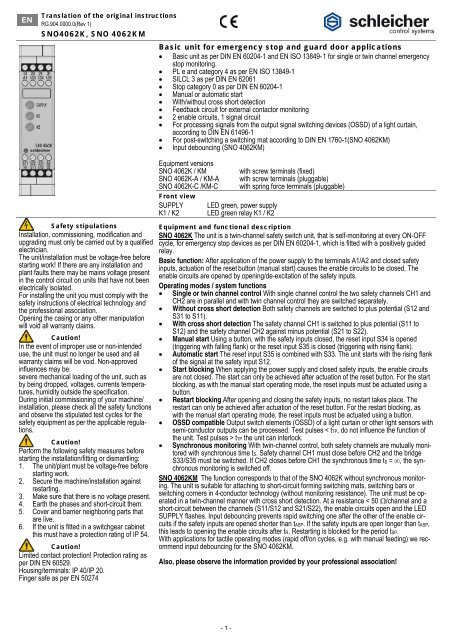
Basic unit for emergency stop and guard door applications<br />
• Basic unit as per DIN EN 60204-1 and EN ISO 13849- 1 for single or twin channel emergency<br />
stop monitoring.<br />
• PL e and category 4 as per EN ISO 13849-1<br />
• SILCL 3 as per DIN EN 62061<br />
• Stop category 0 as per DIN EN 60204-1<br />
• Manual or automatic start<br />
• With/without cross short detection<br />
• Feedback circuit for external contactor monitoring<br />
• 2 enable circuits, 1 signal circuit<br />
• For processing signals from the output signal switching devices (OSSD) of a light curtain,<br />
according to DIN EN 61496-1<br />
• For post-switching a switching mat according to DIN EN 1760-1(SNO 4062KM)<br />
• Input debouncing (SNO 4062KM)<br />
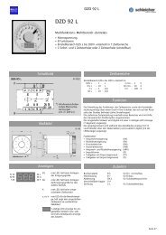
Equipment versions<br />
SNO 4062K / KM<br />
SNO 4062K-A / KM-A<br />
SNO 4062K-C /KM-C<br />
Front view<br />
SUPPLY<br />
K1 / K2<br />
with screw terminals (fixed)<br />
with screw terminals (pluggable)<br />
with spring force terminals (pluggable)<br />
LED green, power supply<br />
LED green relay K1 / K2<br />
Equipment and functional description<br />
SNO 4062K The unit is a twin-channel safety switch unit, that is self-monitoring at every ON-OFF<br />
cycle, for emergency stop devices as per DIN EN 60204-1, which is fitted with a positively guided<br />
relay.<br />
Basic function: After application of the power supply to the terminals A1/A2 and closed safety<br />
inputs, actuation of the reset button (manual start) causes the enable circuits to be closed. The<br />
enable circuits are opened by opening/de-excitation of the safety inputs.<br />
Operating modes / system functions<br />
• Single or twin channel control With single channel control the two safety channels CH1 and<br />
CH2 are in parallel and with twin channel control they are switched separately.<br />
• Without cross short detection Both safety channels are switched to plus potential (S12 and<br />
S31 to S11).<br />
• With cross short detection The safety channel CH1 is switched to plus potential (S11 to<br />
S12) and the safety channel CH2 against minus potential (S21 to S22).<br />
• Manual start Using a button, with the safety inputs closed, the reset input S34 is opened<br />
(triggering with falling flank) or the reset input S35 is closed (triggering with rising flank).<br />
• Automatic start The reset input S35 is combined with S33. The unit starts with the rising flank<br />
of the signal at the safety input S12.<br />
• Start blocking When applying the power supply and closed safety inputs, the enable circuits<br />
are not closed. The start can only be achieved after actuation of the reset button. For the start<br />
blocking, as with the manual start operating mode, the reset inputs must be actuated using a<br />
button.<br />
• Restart blocking After opening and closing the safety inputs, no restart takes place. The<br />
restart can only be achieved after actuation of the reset button. For the restart blocking, as<br />
with the manual start operating mode, the reset inputs must be actuated using a button.<br />
• OSSD compatible Output switch elements (OSSD) of a light curtain or other light sensors with<br />
semi-conductor outputs can be processed. Test pulses < tTP, do not influence the function of<br />
the unit. Test pulses > tTP the unit can interlock.<br />
• Synchronous monitoring With twin-channel control, both safety channels are mutually monitored<br />
with synchronous time tS. Safety channel CH1 must close before CH2 and the bridge<br />
S33/S35 must be switched. If CH2 closes before CH1 the synchronous time tS = ∞, the synchronous<br />
monitoring is switched off.<br />
SNO 4062KM The function corresponds to that of the SNO 4062K without synchronous monitoring.<br />
The unit is suitable for attaching to short-circuit forming switching mats, switching bars or<br />
switching corners in 4-conductor technology (without monitoring resistance). The unit must be operated<br />
in a twin-channel manner with cross short detection. At a resistance < 50 Ω/channel and a<br />
short-circuit between the channels (S11/S12 and S21/S22), the enable circuits open and the LED<br />
SUPPLY flashes. Input debouncing prevents rapid switching one after the other of the enable circuits<br />
if the safety inputs are opened shorter than tASP. If the safety inputs are open longer than tASP,<br />
this leads to opening the enable circuits after tR. Restarting is blocked for the period tSP.<br />
With applications for tactile operating modes (rapid off/on cycles, e.g. with manual feeding) we recommend<br />
input debouncing for the SNO 4062KM.<br />
Also, please observe the information provided by your professional association!<br />
- 1 -
Intended use<br />
The units are safety switchgear. They must only be used as part of the protection devices on machines for the purpose of personal, material and machine protection.<br />
Notes<br />
• The actual performance level achieved and the safety category as per EN ISO 13849-1 depend on the external switching, the selection of command<br />
generator and its arrangement on the machine.<br />
• The user must carry out a risk assessment as per DIN EN ISO 12100.<br />
• On this basis you must carry out validation of the entire installation in accordance with the applicable standards.<br />
• The quoted performance level (PL) is only reached if an average number of switching cycles is not exceeded, depending on the loading of the unit (see<br />
EN ISO 13849-1, Table C.1) and the specific application (see EN ISO 13849-1, C.2.4 and Table K.1). Using an assumed B10d value for maximum load<br />
of 400,000 we get, for example, a maximum cycle number of 400,000 / 0.1 x 30 = 133,333 switching cycles/year<br />
• Operating the unit outside the specification can lead to functional errors or destruction of the unit.<br />
• The supply input A1 also serves as the control input and this means that short interruptions or a drop below UB can lead to switching of the enable circuits.<br />
• You must always maintain the stated time periods when operating the unit, otherwise the unit could lock out. The lock-out can be canceled by proper<br />
opening of the safety inputs.<br />
• To duplicate the enable circuits you can use the extension units from the SNE range or external contactors with positively guided contacts.<br />
• The unit and the contacts must be protected with a max. l 6 A fuse operating class gG.<br />
• The units are equipped with an overload protection (in the event of a short-circuit). After elimination of the cause of the fault, the unit will be ready for<br />
operation after approx. 3 seconds.<br />
• The control output S11 serves exclusively for connecting command generators as per the instruction manual and not for the connection of external consumers,<br />
such as lamps, relays or contactors.<br />
• If the unit is fitted in a switchgear cabinet, this must have a protection rating of IP 54.<br />
EU declaration of conformity (extract)<br />
Type: Basic unit for emergency stop and guard door applications SNO 4062K / SNO 4062 KM<br />
The manufacturer named below hereby declares that the product complies with the stipulations of the EU Directives stated below and complies with<br />
the applicable standards for use.<br />
<strong>Schleicher</strong> Electronic GmbH & Co. KG<br />
Pichelswerderstrasse 3-5<br />
D-13597 Berlin<br />
Person responsible for technical documentation:<br />
Peter Brinkmann<br />
Development manager at <strong>Schleicher</strong><br />
Applicable Directives:<br />
Machinery Directive 2006/42/EU<br />
EMC Directive 2004/108/EU<br />
Number of EU Type Approval Certificate: ET11041<br />
The full signed EU declaration of conformity is to be found at www.schleicher-electronic.com<br />
Information "Any safety functions have not been evaluated by UL. The device was evaluated with regards to the risk of shock and fire only."<br />
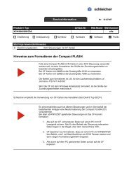
Functional diagram with manual start SNO 4062K (Installation 1)<br />
A1/A2<br />
S12<br />
S31/S22<br />
S34<br />
K1<br />
K2<br />
13/14<br />
23/24<br />
31/32<br />
tM = minimum switch-on time, tA1 = response time, tTP = test pulse time,<br />
tR = fallback time, tW = time for readiness for operation again<br />
Functional diagram with automatic start SNO 4062KM (Installation 2)<br />
A1/A2<br />
S12<br />
S31/S22<br />
S35<br />
Block (internal)<br />
K1<br />
K2<br />
13/14<br />
23/24<br />
31/32<br />
tSP = blocking time, tA2 = response time, tTP = test pulse time, tASP = block response<br />
time, tR = fallback time, tW = time for readiness for operation again<br />
- 2 -
Technical data<br />
Power supply circuit SNO 4062K SNO 4062KM<br />
Nominal voltage UN AC/DC 24 V<br />
Rated power DC 2.0 W 2.1 W<br />
Rated power AC 2.4 W / 4.4 VA 2.5 W / 4.6 VA<br />
Ripple 2.4 Vpp<br />
Nominal frequency 50 ... 60 Hz<br />
Operating voltage range 0.85 ... 1.1 x UN<br />
Fusing for control circuit supply short-circuit resistant<br />
(PTC resistance)<br />
- 3 -<br />
short-circuit resistant<br />
(electronic fuse)<br />
Control circuit<br />
Nominal output voltage S11, S33 against S21 DC 22 V<br />
Output current / peak current<br />
Input voltage range<br />
100 mA / 2000 mA 100 mA / 300 mA<br />
High DC 17.4 V to DC 26.4 V<br />
Low DC -3.0 V to DC +5.0 V<br />
Nominal current / peak current S12, S31/S22 40 mA / 100 mA<br />
Nominal current / peak current S34, S35 5 mA / 50 mA<br />
Permissible test pulse time tTP / test frequency ≤1000 μs and ≤10 s-1 Response time tA1 S34<br />
Response time tA2 S35<br />
Minimum switch-on duration tM S34, S35<br />
200 ms to 500 ms<br />
20 ms to 40 ms<br />
> 50 ms<br />
20 ms to 80 ms<br />
Blocking time tSP --- 70 ms to 130 ms<br />
Block response time tASP --- > 7 ms<br />
Reavailability time tW ≥40 ms ≥150 ms<br />
Fallback time tR K1, K2 < 25 ms<br />
Synchronous monitoring time tS approx. 200 ms --<br />
Maximum resistance for short-circuit forming switching mats<br />
inclusive connection lines<br />
--- ≤ 50 Ω<br />
Line resistance ≤ 70 Ω<br />
Output circuit<br />
Enable circuits<br />
Contact allocation 2 NO, positively guided; B300; R300<br />
Nominal switching voltage Un AC 240 V / DC 300 V<br />
Max. continuous current In per circuit 240 VAC / 6 A; 24 VDC / 5 A<br />
Max. total current of all circuits 12 A<br />
Use category as per DIN EN 60947-5-1<br />
AC-15: Ue 230 V, Ie 4 A (360 h -1 ) DC-13: Ue 24 V, Ie 4 A (360 h -1 )<br />
AC-15: Ue 230 V, Ie 3 A (3600 h-1 ) DC-13: Ue 24 V, Ie 2.5 A (3600 h-1 Fused short-circuit current as per DIN EN 60947-5-1<br />
)<br />
1000 A<br />
Mechanical service life 10 x 106 Signal circuits<br />
cycles<br />
Contact allocation 1 NC, parallel, positively guided<br />
Nominal switching voltage Un AC 240 V / DC 300 V<br />
Max. continuous current In per circuit 6 A<br />
Use category as per DIN EN 60947-5-1<br />
AC-15: Ue 230 V, Ie 4 A (360 h -1 ) DC-13: Ue 24 V, Ie 4 A (360 h -1 )<br />
AC-15: Ue 230 V, Ie 3 A (3600 h -1 ) DC-13: Ue 24 V, Ie 2.5 A (3600 h -1 )<br />
Mechanical service life 10 x 10 6 cycles<br />
General data<br />
Air and creepage distances between the current circuits as per DIN EN 60664-1<br />
Rated surge voltage 4 kV<br />
Contamination level of the unit: internal/external 2/3<br />
Rated voltage AC 300 V<br />
Protection rating as per DIN EN 60529: housing/terminals IP 40 / IP 20<br />
Ambient/bearing temperature -25 ... +55 / -25 ... +75 °C<br />
Weight 0.21 kg<br />
Terminal and connection data<br />
Single core or fine wire 1 x 0.14 mm² to 2.5 mm² 2 x 0.14 mm² to 0.75 mm²<br />
Stripped length max. 8 mm<br />
Fine wire with core ferule as per DIN 46228 1 x 0.25 mm² to 2.5 mm² 2 x 0.25 mm² to 0.5 mm²<br />
Maximum tightening torque 0.5 to 0.6 Nm<br />
For UL and CSA Approvals<br />
Connection cross-sections AWG 26 - 14<br />
use copper conductors only; 60°C / 75°C (140°F / 167°F)<br />
Maximum tightening torque 5 – 7 in-lbs (0,56 – 0,79 Nm)
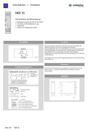
Connection circuit diagram Dimensions<br />
Installation<br />
Observe the connection circuit diagram when installing.<br />
1 Emergency stop, single channel with manual start<br />
1.1 RESET (with reset button monitoring S34)<br />
1.2 Bridge<br />
2 OSSD control, twin channel not cross short detecting<br />
2.1 Bridge, RESET with automatic start<br />
2.2 Bridge, CH2-<br />
3 Emergency stop, twin channel cross short detecting with manual start<br />
3.1 RESET (with reset button monitoring S34)<br />
3.2 Bridge, CH2+<br />
4 Guard door application, twin channel cross short detecting, synchronous<br />
monitoring (S1 must be actuated before S2)<br />
4.1 RESET with automatic start<br />
4.2 Bridge, CH2+<br />
5 2 Enable circuits,<br />
1 signal circuit<br />
6 Supply voltage<br />
Assembly Disassembly<br />
1 3<br />
Hook the relay onto the top-hat<br />
Push the relay down in the direction<br />
rail.<br />
of the arrow.<br />
Subject to modifications<br />
Company headquarters:<br />
<strong>Schleicher</strong> Electronic GmbH & Co. KG<br />
Pichelswerderstr. 3-5<br />
13597 Berlin<br />
2 4<br />
Snap the relay onto the top-hat<br />
rail using slight pressure in the<br />
direction of the arrow.<br />
- 4 -<br />
Telephone 0049 (0)30 33005-0<br />
Telefax 0049 (0)30 33005-344<br />
When the relay is pushed down,<br />
release it from the retainer in the<br />
direction of the arrow and remove it<br />
from the top-hat rail.<br />
www.schleicher-electronic.com<br />
info@schleicher-electronic.com