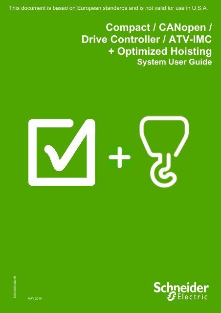
Compact / CANopen /Drive Controller / ATV-IMC ... - Schneider Electric
Compact / CANopen /Drive Controller / ATV-IMC ... - Schneider Electric
Compact / CANopen /Drive Controller / ATV-IMC ... - Schneider Electric

Create successful ePaper yourself
Turn your PDF publications into a flip-book with our unique Google optimized e-Paper software.
This document is based on European standards and is not valid for use in U.S.A.<br />
EIO0000000289<br />
MAY 2010<br />
<strong>Compact</strong> / <strong>CANopen</strong> /<br />
<strong>Drive</strong> <strong>Controller</strong> / <strong>ATV</strong>-<strong>IMC</strong><br />
+ Optimized Hoisting<br />
System User Guide
Contents<br />
Important Information ................................................................................................................................................3<br />
Before You Begin..................................................................................................................4<br />
Introduction.................................................................................................................................................................6<br />
Abbreviations........................................................................................................................7<br />
Glossary ................................................................................................................................8<br />
Application Source Code .....................................................................................................9<br />
Typical Applications...........................................................................................................10<br />
System.......................................................................................................................................................................11<br />
Architecture.........................................................................................................................12<br />
Installation...........................................................................................................................15<br />
Hardware ..........................................................................................................................................................18<br />
Software ...........................................................................................................................................................32<br />
Communication ...............................................................................................................................................33<br />
Implementation ...................................................................................................................40<br />
Communication Setup........................................................................................................42<br />
<strong>Controller</strong> .........................................................................................................................................................44<br />
HMI....................................................................................................................................................................72<br />
Devices.............................................................................................................................................................79<br />
Altivar 312 ...................................................................................................................................................80<br />
Altivar 71 .....................................................................................................................................................86<br />
Lexium 32A ...............................................................................................................................................................91<br />
Advantys OTB ............................................................................................................................................92<br />
Appendix ...................................................................................................................................................................95<br />
The Hoisting Application ...................................................................................................95<br />
Application Specifics......................................................................................................................................96<br />
Application Functions ..................................................................................................................................101<br />
Detailed Component List .................................................................................................115<br />
Component Protection Classes.......................................................................................118<br />
Environmental Characteristics........................................................................................118<br />
Component Features........................................................................................................119<br />
Contact ....................................................................................................................................................................124<br />
Optimized <strong>CANopen</strong> <strong>ATV</strong>-<strong>IMC</strong> <strong>Schneider</strong> <strong>Electric</strong> 2
Important Information<br />
NOTICE Read these instructions carefully, and look at the equipment to become familiar with<br />
the device before trying to install, operate, or maintain it. The following special<br />
messages may appear throughout this documentation or on the equipment to warn of<br />
potential hazards or to call attention to information that clarifies or simplifies a<br />
procedure.<br />
The addition of this symbol to a Danger or Warning safety label indicates that an<br />
electrical hazard exists, which will result in personal injury if the instructions are not<br />
followed.<br />
This is the safety alert symbol. It is used to alert you to potential personal injury<br />
hazards. Obey all safety messages that follow this symbol to avoid possible injury or<br />
death.<br />
DANGER<br />
DANGER indicates an imminently hazardous situation, which, if not avoided, will result in<br />
death or serious injury.<br />
WARNING<br />
WARNING indicates a potentially hazardous situation, which, if not avoided, can result in<br />
death, serious injury, or equipment damage.<br />
CAUTION<br />
CAUTION indicates a potentially hazardous situation, which, if not avoided, can result in<br />
injury or equipment damage.<br />
PLEASE<br />
NOTE<br />
<strong>Electric</strong>al equipment should be installed, operated, serviced, and maintained only by<br />
qualified personnel. No responsibility is assumed by <strong>Schneider</strong> <strong>Electric</strong> for any<br />
consequences arising out of the use of this material.<br />
A qualified person is one who has skills and knowledge related to the construction<br />
and operation of electrical equipment and the installation, and has received safety<br />
training to recognize and avoid the hazards involved<br />
© 2008 <strong>Schneider</strong> <strong>Electric</strong>. All Rights Reserved.<br />
Optimized <strong>CANopen</strong> <strong>ATV</strong>-<strong>IMC</strong> <strong>Schneider</strong> <strong>Electric</strong> 3
Before You Begin<br />
Do not use this product on machinery lacking effective point-of-operation guarding. Lack of effective point-ofoperation<br />
guarding on a machine can result in serious injury to the operator of that machine.<br />
WARNING<br />
UNGUARDED MACHINERY CAN CAUSE SERIOUS INJURY<br />
Do not use this software and related automation products on equipment which does not have<br />
point-of-operation protection.<br />
Do not reach into machine during operation.<br />
Failure to follow these instructions can cause death, serious injury or equipment<br />
damage.<br />
This automation equipment and related software is used to control a variety of industrial processes. The type or<br />
model of automation equipment suitable for each application will vary depending on factors such as the control<br />
function required, degree of protection required, production methods, unusual conditions, government regulations,<br />
etc. In some applications, more than one processor may be required, as when backup redundancy is needed.<br />
Only the user can be aware of all the conditions and factors present during setup, operation and maintenance of<br />
the machine; therefore, only the user can determine the automation equipment and the related safeties and<br />
interlocks which can be properly used. When selecting automation and control equipment and related software for<br />
a particular application, the user should refer to the applicable local and national standards and regulations. A<br />
“National Safety Council’s” Accident Prevention Manual also provides much useful information.<br />
In some applications, such as packaging machinery, additional operator protection such as point-of-operation<br />
guarding must be provided. This is necessary if the operator’s hands and other parts of the body are free to enter<br />
the pinch points or other hazardous areas and serious injury can occur. Software products by itself cannot protect<br />
an operator from injury. For this reason the software cannot be substituted for or take the place of point-ofoperation<br />
protection.<br />
Ensure that appropriate safeties and mechanical/electrical interlocks for point-of-operation protection have been<br />
installed and are operational before placing the equipment into service. All mechanical/electrical interlocks and<br />
safeties for point-of-operation protection must be coordinated with the related automation equipment and software<br />
programming.<br />
NOTE: Coordination of safeties and mechanical/electrical interlocks for point-of-operation protection is<br />
outside the scope of this document.<br />
START UP AND TEST<br />
Before using electrical control and automation equipment for regular operation after installation, the system should<br />
be given a start up test by qualified personnel to verify correct operation of the equipment. It is important that<br />
arrangements for such a check be made and that enough time is allowed to perform complete and satisfactory<br />
testing.<br />
Optimized <strong>CANopen</strong> <strong>ATV</strong>-<strong>IMC</strong> <strong>Schneider</strong> <strong>Electric</strong> 4
CAUTION<br />
EQUIPMENT OPERATION HAZARD<br />
Verify that all installation and set up procedures have been completed.<br />
Before operational tests are performed, remove all blocks or other temporary holding means<br />
used for shipment from all component devices.<br />
Remove tools, meters and debris from equipment.<br />
Failure to follow these instructions can result in injury or equipment damage.<br />
Follow all start up tests recommended in the equipment documentation. Store all equipment documentation for<br />
future reference.<br />
Software testing must be done in both simulated and real environments.<br />
Verify that the completed system is free from all short circuits and grounds, except those grounds installed<br />
according to local regulations (according to the National <strong>Electric</strong>al Code in the U.S.A, for instance). If high-potential<br />
voltage testing is necessary, follow recommendations in equipment documentation to prevent accidental<br />
equipment damage.<br />
Before energizing equipment:<br />
• Remove tools, meters, and debris from equipment.<br />
• Close the equipment enclosure door.<br />
• Remove ground from incoming power lines.<br />
• Perform all startup tests recommended by the manufacturer.<br />
OPERATION AND ADJUSTMENTS<br />
The following precautions are from NEMA Standards Publication ICS 7.1-1995 (English version prevails):<br />
Regardless of the care exercised in the design and manufacture of equipment or in the selection and rating of<br />
components, there are hazards that can be encountered if such equipment is improperly operated.<br />
It is sometimes possible to misadjust the equipment and thus produce unsatisfactory or unsafe operation. Always<br />
use the manufacturer’s instructions as a guide for functional adjustments. Personnel who have access to these<br />
adjustments should be familiar with the equipment manufacturer’s instructions and the machinery used with the<br />
electrical equipment.<br />
Only those operational adjustments actually required by the operator should be accessible to the operator. Access<br />
to other controls should be restricted to prevent unauthorized changes in operating characteristics.<br />
UNEXPECTED EQUIPMENT OPERATION<br />
WARNING<br />
Only use software tools approved by <strong>Schneider</strong> <strong>Electric</strong> for use with this equipment.<br />
Update your application program every time you change the physical hardware configuration.<br />
Failure to follow these instructions can cause death, serious injury or equipment<br />
damage.<br />
Optimized <strong>CANopen</strong> <strong>ATV</strong>-<strong>IMC</strong> <strong>Schneider</strong> <strong>Electric</strong> 5
Introduction<br />
Introduction<br />
This document is intended to provide a quick introduction to the described system. It is not<br />
intended to replace any specific product documentation, nor any of your own design<br />
documentation. On the contrary, it offers additional information to the product<br />
documentation, for installing, configuring and implementing the system.<br />
The architecture described in this document is not a specific product in the normal<br />
commercial sense. It describes an example of how <strong>Schneider</strong> <strong>Electric</strong> and third-party<br />
components may be integrated to fulfill an industrial application.<br />
A detailed functional description or the specification for a specific user application is not<br />
part of this document. Nevertheless, the document outlines some typical applications<br />
where the system might be implemented.<br />
The architecture described in this document has been fully tested in our laboratories using<br />
all the specific references you will find in the component list near the end of this document.<br />
Of course, your specific application requirements may be different and will require<br />
additional and/or different components. In this case, you will have to adapt the information<br />
provided in this document to your particular needs. To do so, you will need to consult the<br />
specific product documentation of the components that you are substituting in this<br />
architecture. Pay particular attention in conforming to any safety information, different<br />
electrical requirements and normative standards that would apply to your adaptation.<br />
It should be noted that there are some major components in the architecture described in<br />
this document that cannot be substituted without completely invalidating the architecture,<br />
descriptions, instructions, wiring diagrams and compatibility between the various software<br />
and hardware components specified herein. You must be aware of the consequences of<br />
component substitution in the architecture described in this document as substitutions may<br />
impair the compatibility and interoperability of software and hardware.<br />
This document describes a generic architecture and hoisting architecture both based on<br />
Altivar <strong>ATV</strong>-<strong>IMC</strong> <strong>Drive</strong> controller S-Type.<br />
Optimized <strong>CANopen</strong> <strong>ATV</strong>-<strong>IMC</strong> <strong>Schneider</strong> <strong>Electric</strong> 6
Abbreviations<br />
Abbreviation Signification<br />
AC Alternating Current<br />
CB Circuit Breaker<br />
CFC Continuous Function Chart – a programming language based on<br />
function chart<br />
DI Digital Input<br />
DO Digital Output<br />
DC Direct Current<br />
DFB Derived Function Blocks<br />
EDS Electronic Data Sheet<br />
E-STOP Emergency Stop<br />
FBD Function Block Diagram – an IEC-61131 programming language<br />
HMI Human Machine Interface<br />
I/O Input/Output<br />
IL Instruction List - a textual IEC-61131 programming language<br />
<strong>IMC</strong> Integrated Machine <strong>Controller</strong><br />
LD Ladder Diagram – a graphic IEC-61131 programming language<br />
PC Personal Computer<br />
POU Programmable Object Unit, Program Section in SoMachine<br />
PDO Process Data Object (<strong>CANopen</strong>)<br />
PS Power Supply<br />
RMS Root Mean Square<br />
RPM Revolutions Per Minute<br />
RPDO Receive Process Data Object (<strong>CANopen</strong>)<br />
SE <strong>Schneider</strong> <strong>Electric</strong><br />
SFC Sequential Function Chart – an IEC-61131 programming language<br />
SDO Service Data Object<br />
ST Structured Text – an IEC-61131 programming language<br />
TPDO Transmit Process Data Object (<strong>CANopen</strong>)<br />
TVDA Tested, Validated and Documented Architecture<br />
VSD Variable Speed <strong>Drive</strong><br />
WxHxD Dimensions : Width, Height and Depth<br />
Optimized <strong>CANopen</strong> <strong>ATV</strong>-<strong>IMC</strong> <strong>Schneider</strong> <strong>Electric</strong> 7
Glossary<br />
Expression Signification<br />
Altivar (<strong>ATV</strong>) SE product name for a family of VSDs<br />
<strong>CANopen</strong> Name for a communications machine bus system<br />
FDT/DTM Field Device Tool / Device Type Manager, technology<br />
Harmony SE product name for a family of switches and indicators<br />
Lexium (LXM) SE product name for a family of servo drives<br />
Magelis SE product name for a family of HMI-Devices<br />
<strong>ATV</strong>-<strong>IMC</strong> SE product name for <strong>Drive</strong> <strong>Controller</strong><br />
Modbus A Communications protocol<br />
OsiSense SE product name for a family of sensors<br />
Phaseo SE product name for a family of power supplies<br />
PLCopen An international standard for industrial controller programming.<br />
Preventa SE product name for a family of safety devices<br />
SoMachine SE product name for an integrated software tool<br />
TeSys SE product name for a family for motor protection devices and<br />
load contactors<br />
Vijeo Designer An SE software product for programming Magelis HMI devices<br />
Optimized <strong>CANopen</strong> <strong>ATV</strong>-<strong>IMC</strong> <strong>Schneider</strong> <strong>Electric</strong> 8
Application Source Code<br />
Introduction Examples of the source code and wiring diagrams used to attain the system function as<br />
described in this document can be downloaded from our website (registration is required,<br />
speak with your <strong>Schneider</strong> <strong>Electric</strong> Application Design Expert).<br />
The example source code is in the form of configuration, application and import files. Use the<br />
appropriate software tool to either open or import the files.<br />
Extension File Type Software Tool Required<br />
AIW Configuration file Advantys Configuration Software<br />
CSV Comma Separated Values, Spreadsheet MS Excel<br />
DCF Device Configuration File Advantys Configuration Software<br />
DOC Document file Microsoft Word<br />
DOP Project File Vijeo Designer Lite<br />
EDS Electronic Data Sheet – Device Definition Industrial standard<br />
ISL Island file, project file Advantys Configuration Software<br />
PDF Portable Document Format - document Adobe Acrobat<br />
PROJECT Project file SoMachine<br />
VDZ Project file Vijeo Designer<br />
Z13 Project archive file EPLAN<br />
Optimized <strong>CANopen</strong> <strong>ATV</strong>-<strong>IMC</strong> <strong>Schneider</strong> <strong>Electric</strong> 9
Typical Applications<br />
Introduction Here you will find a list of the typical applications, and market segments, where this<br />
system or subsystem can be applied:<br />
Hoisting<br />
Self-erecting<br />
Tower crane<br />
Gantry crane<br />
Overhead traveling crane<br />
Textile<br />
Opening and closing machines<br />
Circular knitting machines<br />
Plucker machines<br />
Blending machines<br />
Carding machines<br />
Drawing frame machines<br />
Combing machines<br />
Ring spinning machines<br />
Pumping<br />
Booster stations<br />
Compressors<br />
Vacuum pumps<br />
Irrigation<br />
Others<br />
Winding / Unwinding machines<br />
Wood working machines<br />
Cutting machines<br />
Sanders<br />
Sawing machines<br />
Optimized <strong>CANopen</strong> <strong>ATV</strong>-<strong>IMC</strong> <strong>Schneider</strong> <strong>Electric</strong> 10
System<br />
Introduction The system chapter describes the architecture, the dimensions, the quantities and different<br />
types of components used within this system.<br />
Optimized <strong>CANopen</strong> <strong>ATV</strong>-<strong>IMC</strong> <strong>Schneider</strong> <strong>Electric</strong> 11
General<br />
Layout<br />
Architecture<br />
The controller in this application is a Altivar <strong>ATV</strong>-<strong>IMC</strong> <strong>Drive</strong> controller. The user can control<br />
the application using the Magelis HMI device. The VSDs, servo drives and OTBs are<br />
connected to the <strong>ATV</strong>-<strong>IMC</strong> via a <strong>CANopen</strong> fieldbus. The example application includes two<br />
functional safety options according to EN ISO 13849-1 standards: an Emergency Stop<br />
function supervised by a Preventa Safety Module (see the appropriate hardware manual),<br />
plus a second Preventa Safety Module to evaluate protective door sensors.<br />
Optimized <strong>CANopen</strong> <strong>ATV</strong>-<strong>IMC</strong> <strong>Schneider</strong> <strong>Electric</strong> 12
Components Hardware:<br />
Main switch type <strong>Compact</strong> NSX100F<br />
TeSys motor circuit breaker GV2L<br />
Phaseo ABL8 power supply<br />
TeSysD load contactors<br />
Altivar <strong>ATV</strong>-<strong>IMC</strong> <strong>Drive</strong> controller<br />
Altivar 71 variable speed drive with OsiSense (Osicoder) encoder<br />
Altivar 312 variable speed drive<br />
Lexium 32A servo drive<br />
Lexium BMH servo motor<br />
Preventa XPS safety module<br />
Harmony XALK Emergency Stop switch with rotation release<br />
Harmony pushbuttons<br />
Magelis XBTGT Graphic display terminal<br />
Advantys OTB distributed I/O island<br />
Quantities of<br />
Components<br />
Degree of<br />
Protection<br />
Cabinet<br />
Technical<br />
Data<br />
Software:<br />
SoMachine V2.0<br />
Advantys Configuration Tool V4.8<br />
For a complete and detailed list of components, the quantities required and the order<br />
numbers, please refer to the components list at the rear of this document.<br />
Not all the components in this configuration are designed to withstand the same<br />
environmental conditions. Some components may need additional protection, such as<br />
housings, depending on the environment in which you intend to use them. For<br />
environmental details of the individual components please refer to the list in the appendix of<br />
this document and the corresponding user manual.<br />
Input<br />
Mains voltage 400 Vac<br />
Power requirement ~ 7.5 kW<br />
Cable size 5 x 2.5 mm² (L1, L2, L3, N, PE)<br />
Cable connection 3 phase + Neutral + Ground<br />
Neutral is needed for 230 Vac (Phase and Neutral)<br />
Output Motor power ratings<br />
4 asynchronous motors (4 poles:1500 RPM)<br />
controlled by <strong>ATV</strong>312 (0.75 kW)<br />
3 asynchronous motors (4 poles:1500 RPM)<br />
controlled by <strong>ATV</strong>71 (0.75 kW)<br />
2 servo motors (BMH type with brake) controlled by<br />
LXM32A (continuous output current : 6 A RMS at<br />
6000 RPM)<br />
Optimized <strong>CANopen</strong> <strong>ATV</strong>-<strong>IMC</strong> <strong>Schneider</strong> <strong>Electric</strong> 13
Functional<br />
Safety Notice<br />
(EN ISO 13849-1<br />
EN IEC 62061)<br />
Emergency<br />
Stop<br />
Safety<br />
Function<br />
The standard and level of functional safety you apply to your application is determined by<br />
your system design and the overall extent to which your system may be a hazard to<br />
people and machinery.<br />
As there are no moving mechanical parts in this application example, category 1<br />
(according to EN ISO 13849-1) has been selected as an optional safety level.<br />
Whether or not this functional safety category should be applied to your system should be<br />
ascertained with a proper risk analysis.<br />
This document is not comprehensive for any systems using the given architecture and<br />
does not absolve users of their duty to uphold the functional safety requirements with<br />
respect to the equipment used in their systems or of compliance with either national or<br />
international safety laws or regulations.<br />
Emergency Stop/Emergency Disconnection function<br />
This function for stopping in an emergency is a protective measure which compliments the<br />
safety functions for the safeguarding of hazardous zones according to prEN ISO 12100-2.<br />
Door guarding<br />
up to Performance Level (PL) = b, Category 1, Safety Integrity Level (SIL) = 1<br />
Dimensions The dimensions of the individual devices used; controller, drive, power supply, etc. require<br />
a main cabinet size of at least 1200 x 1800 x 600 mm (WxHxD).<br />
The HMI display, illuminated indicators such as “SYSTEM ON“, “SYSTEM OFF“ or<br />
“ACKNOWLEDGE EMERGENCY OFF” as well as the Emergency Stop switch itself, can<br />
be built into the door of the cabinet.<br />
Optimized <strong>CANopen</strong> <strong>ATV</strong>-<strong>IMC</strong> <strong>Schneider</strong> <strong>Electric</strong> 14
Introduction<br />
Assembly<br />
Front side<br />
Installation<br />
This chapter describes the steps necessary to set up the hardware and configure the<br />
software required to fulfill the described function of the application.<br />
Optimized <strong>CANopen</strong> <strong>ATV</strong>-<strong>IMC</strong> <strong>Schneider</strong> <strong>Electric</strong> 15
Main rack<br />
interior<br />
Optimized <strong>CANopen</strong> <strong>ATV</strong>-<strong>IMC</strong> <strong>Schneider</strong> <strong>Electric</strong> 16
Notes The components designed for installation in a cabinet, i.e. safety modules, circuit breakers,<br />
contactors, motor circuit breakers, power supply and Advantys OTB I/O modules can be<br />
mounted on a 35 mm DIN rail.<br />
Main switch, Lexium 32A servo drives and Altivar 312, Altivar 71 variable speed drives are<br />
screwed directly onto the mounting plate. Alternatively if an adapter is used, the Altivar 312<br />
and Altivar 71 can be mounted on a DIN rail.<br />
The Emergency Stop button, the door guard switches and the pushbutton housing for the<br />
display and acknowledgement indicators are designed for on-wall mounting in the field. All<br />
switches (except the door guard switch) can also be installed directly in a control cabinet<br />
(e.g., in a cabinet door) without special housings.<br />
There are two options for installing XB5 pushbuttons or indicator lamps. These can be<br />
installed either in a 22 mm hole, e.g., drilled into the front door of the control cabinet, or in<br />
an XALD-type housing suitable for up to 5 pushbuttons or indicator lamps. The XALD<br />
pushbutton housing is designed for backplane assembly or direct wall mounting (IP54<br />
protection degree).<br />
400 Vac 3-phase wiring between the main circuit breaker, drives, motor starters and motors.<br />
230 Vac 1-phase wiring between the main circuit breaker and Lexium servo drives<br />
230 Vac 1-phase wiring between the main circuit breaker and primary side of the 24 Vdc<br />
power supply<br />
24 Vdc wiring for the control circuits, the controller’s power supply, the I/O modules and the<br />
HMI.<br />
The individual components must be interconnected in accordance with the detailed circuit<br />
diagram in order to ensure that it works correctly.<br />
<strong>CANopen</strong> cables are installed for the communications link between the controller and the<br />
<strong>ATV</strong>312, LXM32A, <strong>ATV</strong>71 and OTB I/O modules.<br />
The Ethernet cable is installed for the communications link between the controller and the<br />
HMI.<br />
Optimized <strong>CANopen</strong> <strong>ATV</strong>-<strong>IMC</strong> <strong>Schneider</strong> <strong>Electric</strong> 17
General<br />
Hardware<br />
General description of the hardware and assembly instructions.<br />
Main Switch<br />
<strong>Compact</strong> NSX100F<br />
LV429003<br />
36 kA 380/415 Vac<br />
Main Switch<br />
<strong>Compact</strong> NSX100F<br />
LV429035<br />
Trip unit TM32D<br />
Thermal-magnetic<br />
32 A<br />
Main Switch<br />
<strong>Compact</strong> NSX100F<br />
Rotary handle<br />
LV429340<br />
Terminal shield<br />
LV429515<br />
Power supply<br />
Phaseo<br />
ABL8RPS24100<br />
Primary 200…500 Vac,<br />
Secondary 24 Vdc,<br />
240 W, 10 A<br />
Rotary handle with red<br />
handle on yellow front<br />
Ir - Thermal protection<br />
Im - Magnetic protection<br />
Terminal shield short<br />
Optimized <strong>CANopen</strong> <strong>ATV</strong>-<strong>IMC</strong> <strong>Schneider</strong> <strong>Electric</strong> 18
Emergency Stop<br />
Switch<br />
(trigger action)<br />
Harmony<br />
XALK178G<br />
Emergency Stop<br />
Harmony<br />
XB5AS844 + B5AZ141<br />
Including Label<br />
ZBY8330<br />
Safety Module<br />
Preventa<br />
XPSAF5130<br />
Optimized <strong>CANopen</strong> <strong>ATV</strong>-<strong>IMC</strong> <strong>Schneider</strong> <strong>Electric</strong> 19
Expansion Module<br />
Preventa<br />
XPSECP5131<br />
to increase the number<br />
of safety output contacts<br />
of the base module.<br />
Motor Circuit Breaker<br />
GV2L08<br />
and<br />
GV2L10<br />
with<br />
auxiliary contact<br />
GVAE11<br />
(1) When installing base modules and modules for<br />
increasing the number of safety contacts into different<br />
electrical enclosures, run separate cables for terminals<br />
U1-13 and U1-23.<br />
(2) Operating status of internal electronic fuse.<br />
Optimized <strong>CANopen</strong> <strong>ATV</strong>-<strong>IMC</strong> <strong>Schneider</strong> <strong>Electric</strong> 20
Load Contactor<br />
TeSysD<br />
LC1D18BL<br />
Signal Lamps and<br />
Illuminated Pushbutton<br />
Harmony Style 5<br />
XB5AVB1<br />
XB5AW36B5<br />
Circuit Breaker<br />
Multi 9<br />
23726<br />
23747<br />
23756<br />
24518<br />
24886<br />
25022<br />
26135<br />
Altivar <strong>ATV</strong>-<strong>IMC</strong><br />
<strong>Drive</strong> <strong>Controller</strong><br />
VW3A3521S0<br />
Is mounted on Altivar 71<br />
drive as option card.<br />
Optimized <strong>CANopen</strong> <strong>ATV</strong>-<strong>IMC</strong> <strong>Schneider</strong> <strong>Electric</strong> 21
Connectors and ports<br />
I/Os and power supply<br />
Optimized <strong>CANopen</strong> <strong>ATV</strong>-<strong>IMC</strong> <strong>Schneider</strong> <strong>Electric</strong> 22
Variable Speed <strong>Drive</strong><br />
Altivar 71<br />
<strong>ATV</strong>71H075N4<br />
3-phase<br />
400 Vac, 0.75 kW<br />
Encoder Interface card<br />
for <strong>ATV</strong>71<br />
VW3A3401<br />
Zero speed torque<br />
Accurate speed<br />
Regulation<br />
Torque accuracy<br />
Shorter response<br />
times on a torque<br />
surge<br />
Improved dynamic<br />
performance in<br />
transient state<br />
Overspeed detection<br />
Load slipping<br />
detection<br />
Optimized <strong>CANopen</strong> <strong>ATV</strong>-<strong>IMC</strong> <strong>Schneider</strong> <strong>Electric</strong> 23
Incremental Encoder<br />
XCC1510PS11X<br />
The encoder is used on<br />
the hoisting motor shaft<br />
and is connected to the<br />
encoder interface card<br />
on the <strong>ATV</strong>71.<br />
Incremental Encoder<br />
10-wire Encoder Cable<br />
XCCPM23121L5<br />
Variable Speed <strong>Drive</strong><br />
Altivar 312<br />
<strong>ATV</strong>312H075N4<br />
3-phase<br />
400 Vac, 0.75 kW<br />
Braking Resistor<br />
for<br />
Altivar 312<br />
VW3A58732<br />
Protected Braking<br />
Resistor, 100 Ω, 28 W at<br />
50 °C<br />
Optimized <strong>CANopen</strong> <strong>ATV</strong>-<strong>IMC</strong> <strong>Schneider</strong> <strong>Electric</strong> 24
Braking Resistor<br />
for<br />
Altivar 71<br />
VW3A7801<br />
Hoist Resistor, 100 Ω,<br />
1.6 kW at 50°C<br />
Servo <strong>Drive</strong><br />
Lexium 32A<br />
LXM32AD18M2<br />
1-phase<br />
230 Vac, continuous<br />
output current:<br />
6 A RMS at 6000 RPM<br />
Servo <strong>Drive</strong><br />
Lexium 32A<br />
LXM32AD18M2<br />
Embedded Human<br />
Machine Interface<br />
Optimized <strong>CANopen</strong> <strong>ATV</strong>-<strong>IMC</strong> <strong>Schneider</strong> <strong>Electric</strong> 25
Servo <strong>Drive</strong><br />
Lexium 32A<br />
1-phase<br />
LXM32AD18M2<br />
Wiring diagram<br />
Power cable connection<br />
to motor (Length 3 m)<br />
Servo <strong>Drive</strong><br />
Lexium 32A<br />
1-phase<br />
LXM32AD18M2<br />
Wiring diagram holding<br />
brake<br />
Servo <strong>Drive</strong><br />
Lexium 32A<br />
1-phase<br />
LXM32AD18M2<br />
Parallel connection DC<br />
bus<br />
Optimized <strong>CANopen</strong> <strong>ATV</strong>-<strong>IMC</strong> <strong>Schneider</strong> <strong>Electric</strong> 26
Servo <strong>Drive</strong><br />
Lexium 32A<br />
1-phase<br />
LXM32AD18M2<br />
Connecting the external<br />
braking resistor<br />
Servo <strong>Drive</strong><br />
Lexium 32A<br />
1-phase<br />
LXM32AD18M2<br />
Wiring diagram power<br />
stage supply voltage for<br />
1-phase device<br />
Optimized <strong>CANopen</strong> <strong>ATV</strong>-<strong>IMC</strong> <strong>Schneider</strong> <strong>Electric</strong> 27
Servo <strong>Drive</strong><br />
Lexium 32A<br />
1-phase<br />
LXM32AD18M2<br />
Wiring diagram motor<br />
encoder<br />
Optimized <strong>CANopen</strong> <strong>ATV</strong>-<strong>IMC</strong> <strong>Schneider</strong> <strong>Electric</strong> 28
Servo <strong>Drive</strong><br />
Lexium 32A<br />
1-phase<br />
LXM32AD18M2<br />
Wiring diagram controller<br />
supply voltage<br />
Optimized <strong>CANopen</strong> <strong>ATV</strong>-<strong>IMC</strong> <strong>Schneider</strong> <strong>Electric</strong> 29
Servo <strong>Drive</strong><br />
Lexium 32A<br />
1-phase<br />
LXM32AD18M2<br />
Wiring diagram, digital<br />
inputs/outputs<br />
Servo Motor<br />
BMH0702T02F2A<br />
with brake<br />
Continuous stall torque :<br />
2.5 Nm at 6000 RPM<br />
Optimized <strong>CANopen</strong> <strong>ATV</strong>-<strong>IMC</strong> <strong>Schneider</strong> <strong>Electric</strong> 30
Distributed I/O<br />
Advantys OTB<br />
OTB1C0DM9LP<br />
<strong>CANopen</strong> interface<br />
module,<br />
14 Digital Inputs,<br />
2 Solid-State Outputs,<br />
6 Relay Outputs,<br />
Removable Screw<br />
Terminal Blocks<br />
I/O Module<br />
Advantys<br />
TM2DDO8TT<br />
8 Digital Source Outputs,<br />
24 Vdc,<br />
Removable Screw<br />
Terminal Block<br />
I/O Module<br />
Advantys<br />
TM2AMM3HT<br />
2 Analog Inputs<br />
(0…10 Vdc / 4…20 mA)<br />
1 Analog Output<br />
(0..10 Vdc / 4..20 mA)<br />
Fu: 0.3 A quick-blow fuse<br />
Optimized <strong>CANopen</strong> <strong>ATV</strong>-<strong>IMC</strong> <strong>Schneider</strong> <strong>Electric</strong> 31
General<br />
Software<br />
The main programming work lies in programming the Altivar <strong>ATV</strong>-<strong>IMC</strong> <strong>Drive</strong> controller, the<br />
configuration of the <strong>CANopen</strong> fieldbus and creating the screens for the HMI display.<br />
Programming the Altivar <strong>ATV</strong>-<strong>IMC</strong> <strong>Drive</strong> controller is done using SoMachine software.<br />
Programming of the Magelis XBTGT2330 HMI is done by using Vijeo Designer which is<br />
integrated into SoMachine software.<br />
The basic configuration of the drives <strong>ATV</strong>71, <strong>ATV</strong>312 and LXM32A is done using the control<br />
panel. The configuration of the Advantys OTB Island is done using the Advantys Configuration<br />
Software.<br />
To use the software packages, your PC must have the appropriate Microsoft Windows<br />
operating system installed:<br />
Windows XP Professional<br />
The software tools have the following default install paths:<br />
SoMachine<br />
C:\Program Files\<strong>Schneider</strong> <strong>Electric</strong>\SoMachine<br />
Vijeo Designer (Installed with SoMachine)<br />
C:\Program Files\<strong>Schneider</strong> <strong>Electric</strong>\Vijeo Designer<br />
Advantys Configuration Software<br />
C:\Program Files\<strong>Schneider</strong> <strong>Electric</strong>\Advantys<br />
Optimized <strong>CANopen</strong> <strong>ATV</strong>-<strong>IMC</strong> <strong>Schneider</strong> <strong>Electric</strong> 32
General<br />
Communication<br />
The TVDA architecture includes two different communication networks or fieldbusses. The<br />
<strong>CANopen</strong> fieldbus connects the <strong>ATV</strong>-<strong>IMC</strong> as <strong>CANopen</strong> Master and Altivar drives,<br />
Advantys OTB, Lexium 32A servo drives as <strong>CANopen</strong> nodes.<br />
All the drives and the I/O-Island are connected via <strong>CANopen</strong> TAPs. The <strong>CANopen</strong><br />
transmission rate is 500 kb/s.<br />
The Altivar <strong>ATV</strong>-<strong>IMC</strong> <strong>Drive</strong> controller and the Magelis XBTGT HMI communicate via<br />
Ethernet network. The download from the PC to <strong>ATV</strong>-<strong>IMC</strong> and to HMI is done using a<br />
single cable connection. The PC has to be connected to the <strong>ATV</strong>-<strong>IMC</strong> and via this<br />
connection the data is also send across to the HMI.<br />
Programming-cable for<br />
<strong>ATV</strong>-<strong>IMC</strong><br />
TCSXCNAMUM3P<br />
Optimized <strong>CANopen</strong> <strong>ATV</strong>-<strong>IMC</strong> <strong>Schneider</strong> <strong>Electric</strong> 33
<strong>CANopen</strong> connection<br />
Altivar 71<br />
Node ID: 1..3<br />
Note :<br />
In case of <strong>CANopen</strong>, the<br />
<strong>CANopen</strong> Tap<br />
TSXCANTDM4 is used<br />
to connect the drive to<br />
the <strong>CANopen</strong> fieldbus<br />
via RJ45 socket.<br />
<strong>CANopen</strong> connection<br />
Altivar 312<br />
Node ID: 4..7<br />
Note :<br />
In case of <strong>CANopen</strong>, the<br />
<strong>CANopen</strong> Tap<br />
TSXCANTDM4 is used<br />
to connect the drive to<br />
the <strong>CANopen</strong> fieldbus<br />
via RJ45 socket.<br />
Optimized <strong>CANopen</strong> <strong>ATV</strong>-<strong>IMC</strong> <strong>Schneider</strong> <strong>Electric</strong> 34
<strong>CANopen</strong> connection<br />
Lexium 32<br />
Node ID: 8..9<br />
Advantys OTB<br />
<strong>CANopen</strong><br />
OTB1CODM9LP<br />
Node ID: 10<br />
(at 500 kbit/s)<br />
Pin Signal Meaning I/O<br />
1. CAN_H CAN interface CAN level<br />
2. CAN_L CAN interface CAN level<br />
3. CAN_0V Reference potential CAN -<br />
4. nc not used -<br />
5. nc not used -<br />
6. nc not used -<br />
7. nc not used -<br />
8. nc not used -<br />
1. Network address (Node-ID x10) encoder wheel<br />
2. Network address (Node-ID x1) encoder wheel<br />
3. Transmission speed encoder wheel<br />
Optimized <strong>CANopen</strong> <strong>ATV</strong>-<strong>IMC</strong> <strong>Schneider</strong> <strong>Electric</strong> 35
Advantys OTB<br />
OTB1C0DM9LP<br />
<strong>CANopen</strong> port<br />
<strong>CANopen</strong> TAP<br />
TSXCANTDM4<br />
4 port <strong>CANopen</strong> junction<br />
box<br />
For the purpose of this<br />
application, the sliding<br />
switch should be set to<br />
OFF if it is not at the end<br />
of the <strong>CANopen</strong> line.<br />
Optimized <strong>CANopen</strong> <strong>ATV</strong>-<strong>IMC</strong> <strong>Schneider</strong> <strong>Electric</strong> 36
<strong>CANopen</strong> TAP<br />
TSXCANTDM4<br />
Note:<br />
When using devices<br />
which require a 24 Vdc<br />
power supply on<br />
<strong>CANopen</strong> line (such as<br />
TeSysU) the 24 Vdc<br />
power must be wired.<br />
Power supply:<br />
V+1 24 Vdc<br />
CG1 0 Vdc<br />
<strong>CANopen</strong> connector<br />
VW3CANKCDF90T,<br />
VW3CANKCDF90TP<br />
These connectors are<br />
used for the link to the<br />
<strong>CANopen</strong> node.<br />
<strong>CANopen</strong> connector<br />
VW3CANKCDF180T<br />
This connector should be<br />
used with <strong>ATV</strong>-<strong>IMC</strong> board<br />
VW3CANKCDF90T,<br />
VW3CANKCDF90TP<br />
VW3CANKCDF180T<br />
Optimized <strong>CANopen</strong> <strong>ATV</strong>-<strong>IMC</strong> <strong>Schneider</strong> <strong>Electric</strong> 37
<strong>CANopen</strong><br />
pre-assembled<br />
connection cable<br />
<strong>CANopen</strong> cable<br />
TSXCANCxy<br />
The cable is available in<br />
various versions (x):<br />
A - Standard<br />
B - No Flame<br />
D - Heavy Duty<br />
and various lengths (y):<br />
50 - for 50 m<br />
100 - for 100 m,<br />
300 - for 300 m.<br />
<strong>CANopen</strong><br />
pre-assembled<br />
connection cable<br />
FTXCN32xx<br />
xx is:<br />
03 = 0.3 m<br />
06 = 0.6 m<br />
10 = 1 m<br />
20 = 2 m<br />
30 = 3 m<br />
50 = 5 m<br />
Used for the connection<br />
between the racks and<br />
the field devices.<br />
TCSCCN4F3M1T<br />
(length: 1 m)<br />
Used for connection<br />
between <strong>ATV</strong>312/71,<br />
LXM32A and<br />
TSXCANTDM4.<br />
TSXCANCADD1<br />
(length: 1 m)<br />
Used for connection<br />
between OTB, TeSysU<br />
and TSXCANTDM4.<br />
PIN Signal Colour<br />
1 Shield -<br />
2 V+ Red<br />
3 GND black<br />
4 CAN_H White<br />
5 CAN_L Blue<br />
Optimized <strong>CANopen</strong> <strong>ATV</strong>-<strong>IMC</strong> <strong>Schneider</strong> <strong>Electric</strong> 38
Ethernet Connection<br />
Magelis HMI<br />
XBTGT2330<br />
The Ethernet<br />
connection<br />
is used to communicate<br />
between <strong>ATV</strong>-<strong>IMC</strong> and<br />
HMI.<br />
Ethernet cable<br />
ConneXium<br />
490NTW00003<br />
Optimized <strong>CANopen</strong> <strong>ATV</strong>-<strong>IMC</strong> <strong>Schneider</strong> <strong>Electric</strong> 39
Introduction<br />
Function<br />
Functional<br />
Layout<br />
Implementation<br />
The implementation chapter describes all the steps necessary to initialize, to configure, to<br />
program and startup the system to achieve the application functions as listed below.<br />
Start up and functional description<br />
1. Ensure all motor circuit breakers and Multi9 circuit breakers are in the ON position.<br />
2. Ensure that the mains switch is in the ON position.<br />
3. Press the "ACKN E-STOP" blue illuminated pushbutton on the main cabinet door<br />
to acknowledge the system is energized. The blue illuminated pushbutton will turn<br />
OFF if the system is energized.<br />
4. Ensure that all machine interlocks are engaged (i.e. the door guard switches)<br />
5. Press the "ACKN DOOR-READY" blue illuminated pushbutton on the motor rack to<br />
acknowledge the system is ready for operation. The blue illuminated pushbutton<br />
will turn OFF if the system is ready for operation.<br />
6. Use Magelis XBTGT HMI to control/monitor the system.<br />
a. The “BUS” and “SAFETY” screens can be used to monitor the network,<br />
system status and alarm messages.<br />
b. The “<strong>ATV</strong>71” screen can be used to control/monitor Altivar 71 variable<br />
speed drives.<br />
c. The “<strong>ATV</strong>312” screen can be used to control/monitor Altivar 312 variable<br />
speed drives.<br />
d. The “LXM32A” screen can be used to control/monitor Lexium 32A servo<br />
drives.<br />
e. The “OTB” screen can be used to observe the status of the OTB I/Os.<br />
Optimized <strong>CANopen</strong> <strong>ATV</strong>-<strong>IMC</strong> <strong>Schneider</strong> <strong>Electric</strong> 40
Course of<br />
Action<br />
Optimized <strong>CANopen</strong> <strong>ATV</strong>-<strong>IMC</strong> <strong>Schneider</strong> <strong>Electric</strong> 41<br />
,
Introduction<br />
Device Links<br />
NOTE<br />
Communication Setup<br />
This chapter describes the data passed via the communication networks or<br />
fieldbusses (e.g. <strong>CANopen</strong> or Ethernet) that are not bound directly with digital or<br />
analog hardware.<br />
The list contains:<br />
The device links<br />
Direction of data flow<br />
Symbolic name and<br />
Bus address of the device concerned.<br />
This application uses <strong>CANopen</strong> fieldbus and Ethernet networks.<br />
The Altivar <strong>ATV</strong>-<strong>IMC</strong> <strong>Drive</strong> controller and Magelis HMI XBTGT are connected<br />
through Ethernet using SoMachine protocol.<br />
The SoMachine protocol over Ethernet connects:<br />
Magelis XBTGT HMI (IP 192.168.100.30)<br />
Altivar <strong>ATV</strong>-<strong>IMC</strong> <strong>Drive</strong> controller (IP 192.168.100.20)<br />
<strong>CANopen</strong> connects the following devices:<br />
1 <strong>ATV</strong>-<strong>IMC</strong> bus master, address 127<br />
3 Altivar 71 variable speed drives, bus addresses 1..3<br />
4 Altivar 312 variable speed drives, bus addresses 4..7<br />
2 Lexium 32A servo drives, bus addresses 8..9<br />
1 Advantys OTB I/O islands, bus addresses 10<br />
The used <strong>CANopen</strong> baudrate is 500kBit/s.<br />
For the data exchange between the <strong>ATV</strong>-<strong>IMC</strong> and the Altivar 71, the Altivar 312, the<br />
Lexium 32A; PLCopen function blocks are used. It is not necessary to configure the<br />
data exchange manually.<br />
Optimized <strong>CANopen</strong> <strong>ATV</strong>-<strong>IMC</strong> <strong>Schneider</strong> <strong>Electric</strong> 42
Datalink <strong>ATV</strong>-<strong>IMC</strong> (<strong>CANopen</strong>-Master, #127) OTB (<strong>CANopen</strong>-Slave #10)<br />
OTB_Node10 Data Direction OTB -> <strong>ATV</strong>-<strong>IMC</strong><br />
Address Name Designation<br />
<strong>ATV</strong>-<strong>IMC</strong> %IB100 usiIput1OTB_10 First input byte (OTB1CODM9LP)<br />
%IB101 usiIput2OTB_10 Second input byte<br />
(OTB1CODM9LP)<br />
Data Direction <strong>ATV</strong>-<strong>IMC</strong> -> OTB<br />
Address Name Designation<br />
%QB36 usiOputOTB_10 First output byte (OTB1CODM9LP)<br />
Optimized <strong>CANopen</strong> <strong>ATV</strong>-<strong>IMC</strong> <strong>Schneider</strong> <strong>Electric</strong> 43
Introduction<br />
<strong>Controller</strong><br />
The controller chapter describes the steps required for the initialization and configuration<br />
and the source program required to fulfill the functions.<br />
Requirements SoMachine is installed on your PC<br />
The Altivar <strong>ATV</strong>-<strong>IMC</strong> <strong>Drive</strong> controller is switched on and running<br />
The <strong>ATV</strong>-<strong>IMC</strong> is connected to the HMI with the Ethernet cable 490NTW00003<br />
The <strong>ATV</strong>-<strong>IMC</strong> is connected to the PC via the USB TCSXCNAMUM3P cable<br />
Create a new<br />
project<br />
Setting up the <strong>ATV</strong>-<strong>IMC</strong> is done as follows:<br />
1<br />
Create a new project<br />
Add an Option Board<br />
Add the <strong>CANopen</strong> fieldbus<br />
Import of the OTB EDS file<br />
Add <strong>CANopen</strong> devices<br />
<strong>ATV</strong> <strong>CANopen</strong> configuration<br />
LXM32A <strong>CANopen</strong> configuration<br />
OTB <strong>CANopen</strong> configuration<br />
Add Library<br />
Add Folder<br />
Add a POU<br />
Task configuration<br />
Configure controller ↔ HMI data exchange<br />
Add Vijeo Designer HMI<br />
Ethernet settings<br />
Communication setting controller ↔ PC<br />
Communication setting controller ↔ HMI<br />
Save the Project<br />
Build Application<br />
Download the controller and HMI program<br />
Login to the controller<br />
Application overview<br />
To create a new project select<br />
Create new Machine.<br />
Optimized <strong>CANopen</strong> <strong>ATV</strong>-<strong>IMC</strong> <strong>Schneider</strong> <strong>Electric</strong> 44
2 Select Start with application.<br />
3 Select under<br />
<strong>Controller</strong> Templates:<br />
<strong>ATV</strong>_<strong>IMC</strong>_Template.project<br />
4 Save the Project at the<br />
desired location and enter a<br />
File name.<br />
In this case the File name is<br />
Optimized_<strong>CANopen</strong>_<strong>ATV</strong>-<br />
<strong>IMC</strong> and Click Save.<br />
5 Click Program.<br />
Optimized <strong>CANopen</strong> <strong>ATV</strong>-<strong>IMC</strong> <strong>Schneider</strong> <strong>Electric</strong> 45
Add an<br />
Option Board<br />
6 The Program window appears<br />
1<br />
2<br />
3<br />
To add an Option board, right<br />
click on Option_Board -><br />
Empty and click on Plug<br />
Device<br />
Select the IO_Extended and<br />
click on Plug Device.<br />
Close the dialog.<br />
The added Option board is<br />
shown at the end of the Local<br />
list.<br />
Double- click on<br />
IO_Extended to open the<br />
Option_Board parameter<br />
Optimized <strong>CANopen</strong> <strong>ATV</strong>-<strong>IMC</strong> <strong>Schneider</strong> <strong>Electric</strong> 46
Add the<br />
<strong>CANopen</strong><br />
fieldbus<br />
4<br />
1<br />
The I/O Mapping dialog box<br />
opens.<br />
The Variable name and the<br />
addresses can be modified;<br />
also the shown addresses can<br />
be used directly in the<br />
controller program.<br />
To update the variables with<br />
the newest I/O data check<br />
Always update variables.<br />
Right click on CANbus and<br />
select:<br />
Add Device...<br />
Note:<br />
The assembling of this<br />
machine is shown chapter<br />
Communication)<br />
2 Select the <strong>CANopen</strong> master:<br />
<strong>CANopen</strong> Optimized<br />
Click on Add Device.<br />
Optimized <strong>CANopen</strong> <strong>ATV</strong>-<strong>IMC</strong> <strong>Schneider</strong> <strong>Electric</strong> 47
Import the<br />
OTB EDS file<br />
3<br />
4<br />
1<br />
2<br />
To set the Baudrate of the<br />
<strong>CANopen</strong> bus, double click on<br />
CAN and select 500000 as a<br />
Baudrate.<br />
To activate the Heartbeat of<br />
<strong>CANopen</strong> fieldbus double-<br />
click the<br />
<strong>CANopen</strong>_Optimized and<br />
check Enable heartbeat<br />
generation.<br />
The Heartbeat time is 400<br />
ms.<br />
The Node ID is 127 for the<br />
<strong>CANopen</strong> master.<br />
To use the extended OTB<br />
island (configured by<br />
Advantys Configuration<br />
Software) you have to import<br />
the OTB eds file.<br />
Select Tools<br />
Device Repository…<br />
In the Device Repository<br />
select Install…<br />
Optimized <strong>CANopen</strong> <strong>ATV</strong>-<strong>IMC</strong> <strong>Schneider</strong> <strong>Electric</strong> 48
Add<br />
<strong>CANopen</strong><br />
devices<br />
3<br />
4<br />
1<br />
Select the OTB EDS file. In<br />
this project the OTB EDS file<br />
is named<br />
OTB_TVD_Opti_<strong>ATV</strong><strong>IMC</strong>.eds<br />
Press Open<br />
Press Close<br />
Right click on the<br />
<strong>CANopen</strong>_Optimized<br />
and select Add Device… in<br />
the pop-up menu.<br />
Optimized <strong>CANopen</strong> <strong>ATV</strong>-<strong>IMC</strong> <strong>Schneider</strong> <strong>Electric</strong> 49
2 In this project the following<br />
devices are connected to the<br />
<strong>CANopen</strong> bus:<br />
3x Altivar 71<br />
4x Altivar 312<br />
2x Lexium 32 A<br />
1x OTB_TVD_Opti_<strong>ATV</strong><strong>IMC</strong><br />
Add each device by clicking on<br />
Add Device. Once you have<br />
added all devices click on<br />
Close.<br />
3 Change the name of the device,<br />
with right click at the relevant<br />
device and open Properties.<br />
Enter the new name e.g<br />
<strong>ATV</strong>71_Node1<br />
and click OK<br />
Note:<br />
The name of the device is also<br />
the AXIS REF name for the<br />
PLCopen functions used in the<br />
application program<br />
Optimized <strong>CANopen</strong> <strong>ATV</strong>-<strong>IMC</strong> <strong>Schneider</strong> <strong>Electric</strong> 50
<strong>ATV</strong><br />
<strong>CANopen</strong><br />
configuration<br />
4 The new devices are now<br />
listed in<br />
<strong>CANopen</strong>_Optimized<br />
1<br />
2<br />
To configure the devices,<br />
double click on the specific<br />
item.<br />
Double click on the <strong>ATV</strong>_71<br />
or <strong>ATV</strong>_312 to open the<br />
dialog.<br />
Set the Node Id<br />
3x <strong>ATV</strong> 71, node 1..3<br />
4x <strong>ATV</strong> 312, node 4..7<br />
Set the recommended<br />
Heartbeat producer time to<br />
400 ms.<br />
Click on Change Properties<br />
Heartbeat consumer… and<br />
check the time.<br />
Minimum value is:<br />
Heartbeat<br />
producer time x 1.5<br />
(e.g. 400 ms x 1.5 = 600 ms)<br />
Note:<br />
These values depend on the<br />
application<br />
Go to<br />
<strong>CANopen</strong> I/O Mapping tab<br />
and check:<br />
Always update variable.<br />
Optimized <strong>CANopen</strong> <strong>ATV</strong>-<strong>IMC</strong> <strong>Schneider</strong> <strong>Electric</strong> 51
LXM32A<br />
<strong>CANopen</strong><br />
configuration<br />
OTB <strong>CANopen</strong><br />
Configuration<br />
1<br />
1<br />
The configuration is done in<br />
the same way as the <strong>ATV</strong><br />
configuration.<br />
<strong>CANopen</strong> addresses are<br />
Node ID: 8..9.<br />
Set the recommended<br />
Heartbeat producer time to<br />
400 ms.<br />
Click on Change Properties<br />
Heartbeat consumer… and<br />
check the time.<br />
Minimum value is:<br />
Heartbeat<br />
producer time x 1.5<br />
(e.g. 400 ms x 1.5 = 600 ms)<br />
Note:<br />
These values depend on the<br />
application<br />
Double click on<br />
OTB_Node10.<br />
Optimized <strong>CANopen</strong> <strong>ATV</strong>-<strong>IMC</strong> <strong>Schneider</strong> <strong>Electric</strong> 52
2<br />
3<br />
4<br />
Check<br />
Enable Expert Settings<br />
and<br />
Enable Heartbeat<br />
Generation.<br />
Set the recommended<br />
Heartbeat producer time to<br />
400 ms.<br />
Click on Change Properties<br />
Heartbeat consumer… and<br />
check the time.<br />
Minimum value is:<br />
Heartbeat<br />
producer time x 1.5<br />
(e.g. 400 ms x 1.5 = 600 ms)<br />
Note:<br />
These values depend on the<br />
application<br />
Go to the PDO Mapping tab<br />
and check:<br />
Receive PDO Para 1<br />
(write output 0 to 7)<br />
and<br />
Transmit PDO Para 1<br />
(read input 0 to 7)<br />
In the <strong>CANopen</strong> I/O Mapping<br />
tab, the OTB inputs and<br />
outputs are mapped to<br />
existing variables.<br />
The name of the variable can<br />
be entered in the Variable<br />
field or select from the global<br />
variable list.<br />
To update the variables with<br />
the newest I/O data check<br />
Always update variables.<br />
Optimized <strong>CANopen</strong> <strong>ATV</strong>-<strong>IMC</strong> <strong>Schneider</strong> <strong>Electric</strong> 53
Add Library<br />
1<br />
2<br />
3<br />
4<br />
To use special functions you<br />
need special libraries. These<br />
can be inserted by double<br />
clicking on Library Manager.<br />
In the Library Manager click<br />
on Add library…<br />
Open tab Placeholder and<br />
add as Placeholder name<br />
SE_Hoisting<br />
Then select<br />
Solution -><br />
Hoisting<br />
for the Hoisting lib.<br />
Click on OK to insert the<br />
library.<br />
Now the new library is in the<br />
Library Manager.<br />
5 If you wish to add more libraries repeat steps 1 to 4.<br />
Optimized <strong>CANopen</strong> <strong>ATV</strong>-<strong>IMC</strong> <strong>Schneider</strong> <strong>Electric</strong> 54
Add Folder<br />
Add a POU<br />
1<br />
2<br />
3<br />
1<br />
In the browser Right click on<br />
Application→ Add Folder…<br />
Type in the Folder name: e.g.<br />
SYSTEM_Control<br />
Click on OK.<br />
To include additional folders,<br />
repeat steps 1 through 2<br />
Right click on<br />
Application→ on folder<br />
SYSTEM_Control →<br />
Add Object…<br />
Optimized <strong>CANopen</strong> <strong>ATV</strong>-<strong>IMC</strong> <strong>Schneider</strong> <strong>Electric</strong> 55
2<br />
3<br />
Select POU and enter a<br />
Name e.g. OTB_Data.<br />
As Type select Program.<br />
As Implementation language<br />
select CFC.<br />
It is possible to select all the<br />
IEC languages and to<br />
generate functions and<br />
function blocks.<br />
Click on Open.<br />
The new POU OTB_Data is<br />
now visible under<br />
Application→<br />
SYSTEM_Control<br />
Double click on<br />
OTB_Data<br />
to open it.<br />
4 The upper frame displays the<br />
declaration section. The lower<br />
frame is for programming. On<br />
the right side is the ToolBox<br />
window. Use drag and drop<br />
with the toolbox to place<br />
example templates in the<br />
programming section.<br />
5 Once you have placed a<br />
template in the programming<br />
section click on ???.<br />
Optimized <strong>CANopen</strong> <strong>ATV</strong>-<strong>IMC</strong> <strong>Schneider</strong> <strong>Electric</strong> 56
6 Type in a name for the<br />
function or function block.<br />
When the first letters are<br />
typed a pop-up menu opens<br />
with hints for the name.<br />
7<br />
In this project example an<br />
UNPACK function was<br />
chosen. The UNPACK<br />
converts bytes to bits.<br />
To instantiate the FB click ???.<br />
8 Type in a name e.g.<br />
mcUnpack1<br />
9<br />
Press Enter<br />
The Auto Declare dialog<br />
opens.<br />
Click on OK to create the<br />
instance.<br />
If you wish to add a comment<br />
do this in the Comment box.<br />
The new FB UNPACK is<br />
instantiated in the header of the<br />
OTB_Data POU.<br />
Optimized <strong>CANopen</strong> <strong>ATV</strong>-<strong>IMC</strong> <strong>Schneider</strong> <strong>Electric</strong> 57
10<br />
11<br />
To connect a variable to an<br />
input place an input field from<br />
the ToolBox on the input side<br />
of the FB and connect the<br />
input box to the FB input by<br />
clicking on the red field and<br />
dragging it to the input of the<br />
FB.<br />
Click on ??? in the input<br />
name field and press F8.<br />
The Input Assistant is<br />
displayed.<br />
Optimized <strong>CANopen</strong> <strong>ATV</strong>-<strong>IMC</strong> <strong>Schneider</strong> <strong>Electric</strong> 58
Task<br />
Configuration<br />
12 In the Input Assistant select<br />
13<br />
14<br />
15<br />
1<br />
Global Variables →<br />
My<strong>Controller</strong> →<br />
CANbus →<br />
<strong>CANopen</strong>_Optimized →<br />
oConfig_Globals_Mapping<br />
and then the variable.<br />
In this project the variable is<br />
the first input byte of the OTB.<br />
Click OK.<br />
This image shows the FB with<br />
the connected input.<br />
Output selection is similar to<br />
input definition. Pick an output<br />
from the toolbox, type in the<br />
name of the variable and press<br />
Enter.<br />
In the Auto Declare dialog<br />
select the<br />
Scope as VAR_GLOBAL,<br />
the Name and the Type.<br />
Confirm with OK.<br />
The VAR_GLOBAL variables<br />
are located in the GVL folder.<br />
All variables located in this<br />
folder can be accessed<br />
throughout the whole<br />
Application. If the variables<br />
are located in the POU, they<br />
can only be accessed by the<br />
POU (local variables).<br />
Next, it is important to insert<br />
minimum one main POU in<br />
the Task Configuration.-><br />
MAST, otherwise no programcode<br />
will be processed.<br />
Optimized <strong>CANopen</strong> <strong>ATV</strong>-<strong>IMC</strong> <strong>Schneider</strong> <strong>Electric</strong> 59
2<br />
Select Categories Programs<br />
(Project) and select the new<br />
POU in the Items list. Then<br />
click OK.<br />
3 It is advantageous to create a<br />
Main POU for every project,<br />
and to call from there all other<br />
POU’s.<br />
4<br />
That helps a lot, because<br />
during commissioning is it<br />
easy to activate or deactivate<br />
POU’s to test separate<br />
modules of your application.<br />
Now the POU is in the MAST<br />
task.<br />
In the upper part of the MAST<br />
task configuration you can<br />
change the Type of the task.<br />
Direct under the Type menu is<br />
the Watchdog field. Set the<br />
Watchdog time to 200 ms.<br />
Optimized <strong>CANopen</strong> <strong>ATV</strong>-<strong>IMC</strong> <strong>Schneider</strong> <strong>Electric</strong> 60
Add Vijeo<br />
Designer HMI<br />
1<br />
To add a Vijeo Designer HMI<br />
unit to the project right click on<br />
Project-name -><br />
Add Device<br />
2 Select the HMI from the list<br />
3<br />
Magelis HMI-><br />
XBTGT2330<br />
Click on Add Device and Close<br />
The new XBTGT2330 is now<br />
listed in the configuration.<br />
NOTE:<br />
With this XBTGT2330 the<br />
Program Vijeo Designer opens<br />
and you can start<br />
programming.<br />
(See chapter HMI)<br />
Optimized <strong>CANopen</strong> <strong>ATV</strong>-<strong>IMC</strong> <strong>Schneider</strong> <strong>Electric</strong> 61
Ethernet<br />
settings<br />
Configure<br />
<strong>Controller</strong> ↔<br />
HMI Data<br />
Exchange<br />
1<br />
2<br />
1<br />
To change the Ethernet<br />
settings double click<br />
Ethernet<br />
Check the fixed IP Address<br />
box and set an IP Address (In<br />
this project 192.168.100.20)<br />
and a Subnet Mask (In this<br />
project 255.255.0.0)<br />
NOTE:<br />
The USB cable<br />
TCSXCNAMUM3P<br />
must be used for the initial<br />
project download. For<br />
subsequent downloads, the<br />
Ethernet connection can be<br />
used.<br />
Right click on:<br />
Application→ Add Object...<br />
Optimized <strong>CANopen</strong> <strong>ATV</strong>-<strong>IMC</strong> <strong>Schneider</strong> <strong>Electric</strong> 62
2<br />
3<br />
Select Symbol configuration<br />
in the Add Object dialog.<br />
Click on Open.<br />
Click on Refresh in the now<br />
open Symbol configuration.<br />
The left window shows the<br />
Available Items.<br />
The right window shows the<br />
Selected variables which can<br />
be used in the HMI.<br />
4 All Variables created in the<br />
user program are shown in<br />
the Selected variables list.<br />
In this project all variables that<br />
are needed for HMI are<br />
located in the GVL folder.<br />
To export variables to the<br />
HMI, select GVL them and<br />
click on [ > ].<br />
5 The right frame lists the<br />
Selected variables which are<br />
available in the HMI.<br />
Optimized <strong>CANopen</strong> <strong>ATV</strong>-<strong>IMC</strong> <strong>Schneider</strong> <strong>Electric</strong> 63
Communication<br />
setting<br />
controller ↔ PC<br />
6 Right click on<br />
Symbol configuration -><br />
Export Symbols to Vijeo-<br />
Designer<br />
to export the variable-list<br />
7 This step must be done in<br />
Vijeo-Designer so that the<br />
variables are there available<br />
for the HMI program:<br />
1<br />
2<br />
Right click on<br />
Variables-><br />
Import Variables From<br />
SoMachine…<br />
to import the variable-list<br />
To configure the<br />
communication gateway<br />
double click on the used<br />
controller.<br />
On the tab Communication<br />
Settings click on:<br />
Add gateway...<br />
Optimized <strong>CANopen</strong> <strong>ATV</strong>-<strong>IMC</strong> <strong>Schneider</strong> <strong>Electric</strong> 64
3<br />
4<br />
5<br />
6<br />
Keep the default settings and<br />
click on OK.<br />
Select Gateway-1 and click<br />
on Scan network.<br />
When the scan is finished, the<br />
devices pop up under the<br />
gateway.<br />
Select the used controller and<br />
click Set active path.<br />
With Edit... the name of the<br />
device can be modified.<br />
A warning pop-up message<br />
appears<br />
Read the message and<br />
confirm<br />
Optimized <strong>CANopen</strong> <strong>ATV</strong>-<strong>IMC</strong> <strong>Schneider</strong> <strong>Electric</strong> 65
Communication<br />
Setting<br />
HMI ↔ PC<br />
Save the<br />
project<br />
7<br />
The used controller is now<br />
marked as active.<br />
That means that the Online<br />
functions are possible (e.g.<br />
program download,<br />
monitoring, online change)<br />
8 NOTE:<br />
1<br />
1<br />
Every <strong>ATV</strong>-<strong>IMC</strong> has a unique<br />
MAC address that is a part of<br />
the default name (in this case:<br />
@0080F4DA008F).<br />
If you would like to change the<br />
default name of your<br />
controller:<br />
click on Edit…<br />
In the displayed pop-up<br />
window go to the<br />
Device Name field and enter<br />
the new unique name for your<br />
controller.<br />
In our example we kept the<br />
factory setting name.<br />
The HMI is mapped to the<br />
controller automatically<br />
To save the project and<br />
change the name click<br />
File -> Save Project As…<br />
Optimized <strong>CANopen</strong> <strong>ATV</strong>-<strong>IMC</strong> <strong>Schneider</strong> <strong>Electric</strong> 66
Build<br />
Application<br />
2<br />
1<br />
2<br />
Enter the File name and click<br />
on Save.<br />
To build the application click<br />
on<br />
Build→<br />
Build ‘Application<br />
Note:<br />
If you wish to build the entire<br />
project (HMI and controller)<br />
click Build All<br />
After the build you are notified<br />
in the Message view as to<br />
whether the build was<br />
successful or not.<br />
If the build was not successful<br />
a compilation error list is<br />
displayed in the Message<br />
field.<br />
Optimized <strong>CANopen</strong> <strong>ATV</strong>-<strong>IMC</strong> <strong>Schneider</strong> <strong>Electric</strong> 67
Download<br />
the controller<br />
and HMI<br />
program<br />
1<br />
2<br />
In Vijeo Designer select the<br />
HMI in the device list.<br />
The HMI is connected with<br />
the controller via Ethernet. In<br />
the Property Inspector enter<br />
the IPAddress of the HMI<br />
To download the application<br />
to the controller and the HMI<br />
click<br />
In SoMachine<br />
Online-><br />
Multiple Download…<br />
Optimized <strong>CANopen</strong> <strong>ATV</strong>-<strong>IMC</strong> <strong>Schneider</strong> <strong>Electric</strong> 68
3<br />
4<br />
5<br />
6<br />
Check the controller and the<br />
HMI application<br />
Click on OK.<br />
Before the download starts a<br />
build of the complete project<br />
is done.<br />
The result of the build is<br />
displayed in the message<br />
window.<br />
The results of the download<br />
to the controller are displayed<br />
in the Multiple Download –<br />
Result window.<br />
Here are two examples:<br />
In the first dialog there was no<br />
change.<br />
And in the second dialog<br />
there was an online change<br />
remove.<br />
Click on Close to close to the<br />
results window.<br />
Once the download to the<br />
controller is finished, the HMI<br />
download starts.<br />
Optimized <strong>CANopen</strong> <strong>ATV</strong>-<strong>IMC</strong> <strong>Schneider</strong> <strong>Electric</strong> 69
Login to<br />
controller<br />
7<br />
1<br />
2<br />
3<br />
4<br />
5<br />
6<br />
The result of the HMI<br />
download is displayed in the<br />
Messages window.<br />
To login to the controller click<br />
Online→<br />
Login<br />
If the controller program is<br />
different from the program on<br />
the PC a message asks you if<br />
you wish to replace the old<br />
controller program.<br />
If you do not wish to replace<br />
the controller program<br />
continue with step 6,<br />
otherwise click Yes to confirm<br />
the download.<br />
The actual download status is<br />
displayed at the bottom of the<br />
main window.<br />
Here you can select to create<br />
a boot project if you wish. A<br />
boot project is stored in<br />
FLASH memory so that a<br />
power loss does not mean<br />
you have to repeat the<br />
download on re-start.<br />
Select Yes to create a boot<br />
application.<br />
The actual creation status is<br />
displayed at the bottom of the<br />
main window<br />
To start the new Application<br />
select<br />
Online→<br />
Start<br />
Note:<br />
By default the controller starts<br />
automatically after program<br />
download.<br />
Optimized <strong>CANopen</strong> <strong>ATV</strong>-<strong>IMC</strong> <strong>Schneider</strong> <strong>Electric</strong> 70
Application<br />
overview<br />
7<br />
1<br />
If everything is running<br />
properly the devices and<br />
folders are marked in green<br />
otherwise they will be marked<br />
in red.<br />
The picture on the right shows<br />
the structure of the<br />
Application.<br />
The program is split in<br />
function-groups with folders.<br />
Optimized <strong>CANopen</strong> <strong>ATV</strong>-<strong>IMC</strong> <strong>Schneider</strong> <strong>Electric</strong> 71
Introduction<br />
Main Window<br />
HMI<br />
This application uses a Magelis XBTGT2330 HMI. This HMI device communicates via the<br />
SoMachine protocol via Ethernet with the controller. The HMI is programmed using the<br />
software tool Vijeo Designer (delivered with SoMachine), described briefly in the following<br />
pages.<br />
The PC with SoMachine is connected via USB cable TCSXCNAMUM3P to the <strong>ATV</strong>-<strong>IMC</strong>, and<br />
from there via Ethernet to the HMI panel use the Ethernet cable 490NTW00003.<br />
NOTE:<br />
The Vijeo Designer Tool is opened and closed via SoMachine software. For more information<br />
see chapter<br />
<strong>Controller</strong>: Add Vijeo Designer HMI<br />
Setting up the HMI is done as follows:<br />
1<br />
Main Window<br />
Communication settings<br />
Create a switch<br />
Create a numeric display<br />
Example screens<br />
After double click on the<br />
XBTGT2330 in SoMachine,<br />
Vijeo Designer opens the HMI<br />
main window.<br />
Optimized <strong>CANopen</strong> <strong>ATV</strong>-<strong>IMC</strong> <strong>Schneider</strong> <strong>Electric</strong> 72
Communication<br />
settings<br />
1<br />
To set the communication<br />
parameters, in the<br />
Navigator select<br />
IO Manager -><br />
SoMachineNetwork02 -><br />
SOM_My<strong>Controller</strong><br />
and click on …<br />
2 In the dialog set the controller<br />
Equipment Address.<br />
3<br />
You will find this address in<br />
SoMachine… (see next step)<br />
… by double clicking the<br />
My<strong>Controller</strong>.<br />
Optimized <strong>CANopen</strong> <strong>ATV</strong>-<strong>IMC</strong> <strong>Schneider</strong> <strong>Electric</strong> 73
Create a<br />
switch<br />
4 In the Communication<br />
Settings tab select the<br />
controller and click on Edit…<br />
5<br />
1<br />
2<br />
The Equipment address of the<br />
controller is displayed under<br />
Device Name.<br />
Select the Switch icon in the<br />
Tool bar<br />
Select the position and<br />
dimension where you wish to<br />
place the button by opening a<br />
rectangle on the display and<br />
pressing enter.<br />
3 In the Switch Settings dialog,<br />
select the variable that should<br />
be linked (Lamp icon) to the<br />
button.<br />
Optimized <strong>CANopen</strong> <strong>ATV</strong>-<strong>IMC</strong> <strong>Schneider</strong> <strong>Electric</strong> 74
4<br />
5<br />
6<br />
Click on the bulb icon (as<br />
indicated in the image above) to<br />
open the Variables List dialog.<br />
Use the tab SoMachine.<br />
Select the required variable and<br />
click OK.<br />
Go to the Label tab.<br />
Here select Label Type: Static<br />
and enter a name for the<br />
button, e.g. Enable.<br />
Once you have finished your<br />
settings click on OK.<br />
The display now shows the<br />
new button.<br />
Optimized <strong>CANopen</strong> <strong>ATV</strong>-<strong>IMC</strong> <strong>Schneider</strong> <strong>Electric</strong> 75
Create a<br />
Numeric<br />
Display<br />
Example<br />
screens<br />
1<br />
2<br />
Click on the Numeric Display<br />
icon in the tool bar.<br />
Select the spot where you want<br />
to position the display by<br />
opening the rectangle and<br />
pressing enter.<br />
3 In the Numeric Display<br />
Settings dialog go to the<br />
General tab.<br />
4<br />
1<br />
In Display Digits you can set<br />
the maximum number of the<br />
digits to be displayed for both<br />
integral and fractional part of<br />
the value.<br />
To link a Variable to the<br />
display click on the bulb icon to<br />
browse for a variable.<br />
Press OK.<br />
The display shows the new<br />
numeric display.<br />
The Home page shows the<br />
Optimized <strong>CANopen</strong> <strong>ATV</strong> <strong>IMC</strong><br />
architecture.<br />
Optimized <strong>CANopen</strong> <strong>ATV</strong>-<strong>IMC</strong> <strong>Schneider</strong> <strong>Electric</strong> 76
2<br />
3<br />
4<br />
5<br />
The “Safety” page shows the<br />
status of the Emergency Stop<br />
relay.<br />
The Bus page shows the state<br />
of all <strong>CANopen</strong> Nodes.<br />
Via the <strong>ATV</strong>71 page it is<br />
possible to control Altivar 71<br />
variable speed drives.<br />
Via the <strong>ATV</strong>312 page it is<br />
possible to control Altivar 312<br />
variable speed drives.<br />
Optimized <strong>CANopen</strong> <strong>ATV</strong>-<strong>IMC</strong> <strong>Schneider</strong> <strong>Electric</strong> 77
6<br />
7<br />
Via the LXM32 page it is<br />
possible to control both<br />
Lexium 32A servo drives.<br />
The OTB page shows the<br />
status of the input and output<br />
bits of the device.<br />
Optimized <strong>CANopen</strong> <strong>ATV</strong>-<strong>IMC</strong> <strong>Schneider</strong> <strong>Electric</strong> 78
Devices<br />
Introduction This chapter describes the steps required to initialize and configure the different<br />
devices required to attain the described system function.<br />
General Altivar 312, Altivar 71 and Lexium 32A drives must be configured by using the local<br />
control panel.<br />
Note .If this is not a new drive, it is recommended to return to the factory settings. If you<br />
need instructions on how to do this, please read the drive documentation.<br />
It is recommended that the controller is in stop mode before parameterizing the<br />
drives.<br />
Optimized <strong>CANopen</strong> <strong>ATV</strong>-<strong>IMC</strong> <strong>Schneider</strong> <strong>Electric</strong> 79
Introduction<br />
Note<br />
Control panel 1<br />
<strong>CANopen</strong><br />
settings<br />
Altivar 312<br />
The <strong>ATV</strong>312 parameters can be entered or modified via the local control panel on the<br />
front of the device.<br />
If this is not a new drive it is recommended to return to the factory settings. If you need<br />
instructions on how to do this, please read the drive documentation.<br />
Jog dial that is a part of the local control panel and can be used for navigation by<br />
turning it clockwise or counter-clockwise. Pressing the jog dial enables the user to<br />
make a selection or confirm information.<br />
The drive parameters can be input using the buttons and the jog dial on the control<br />
panel of the Altivar.<br />
1 Using the buttons on the front<br />
panel, select the sub-menu<br />
Communication.<br />
2 In the Communication (COM)<br />
sub-menu input the <strong>CANopen</strong><br />
address in the parameter<br />
AdC0. In the example<br />
application the addresses for<br />
the four drives are 4 to 7<br />
Optimized <strong>CANopen</strong> <strong>ATV</strong>-<strong>IMC</strong> <strong>Schneider</strong> <strong>Electric</strong> 80
3<br />
Also in the Communication<br />
(COM-) sub-menu, in the<br />
parameter BdC0, set the<br />
Baudrate to 500.0 (kBits).<br />
4 For the <strong>ATV</strong>312 to operate with the new address or Baudrate, a power cycle (on,<br />
off, on) is required.<br />
Optimized <strong>CANopen</strong> <strong>ATV</strong>-<strong>IMC</strong> <strong>Schneider</strong> <strong>Electric</strong> 81
Changing the<br />
Access Level<br />
LAC<br />
1<br />
To set the parameters for the brake function a higher access level (L3) is<br />
required.<br />
2 To go to expert mode L3:<br />
Select CtL-<br />
[COMMAND] and<br />
press enter<br />
Select LAC [ACCESS<br />
LEVEL] and press<br />
enter<br />
L1 (Level 1) is<br />
displayed<br />
Select L3 (Level 3)<br />
and press enter for 2<br />
seconds to set the<br />
new level.<br />
Return to the LAC with ESC.<br />
Return to the CtL- with ESC.<br />
Optimized <strong>CANopen</strong> <strong>ATV</strong>-<strong>IMC</strong> <strong>Schneider</strong> <strong>Electric</strong> 82
Brake<br />
settings<br />
1 The r2 relay output is used for brake control.<br />
2 To assign the r2 relay output :<br />
Select FUn-<br />
[APPLICATION<br />
FUNCT.] and press<br />
enter<br />
Select bLC- [BRAKE<br />
LOGIC CONTROL]<br />
and press enter<br />
Select bLC [BRAKE<br />
LOGIC CONTROL]<br />
and press enter<br />
Select r2 and press<br />
enter.<br />
Set the parameters to the<br />
values shown here on the<br />
right.<br />
Note :<br />
These parameters are for the<br />
test machine only. They are<br />
NOT VALID for every<br />
machine.<br />
After all parameters are set<br />
return to the bLC with ESC.<br />
Return to the bLC- with ESC.<br />
Return to the Fun- with ESC.<br />
Optimized <strong>CANopen</strong> <strong>ATV</strong>-<strong>IMC</strong> <strong>Schneider</strong> <strong>Electric</strong> 83
Limit<br />
switches<br />
configuration<br />
1 The input LI5 and LI6 are assigned to Limit switches<br />
2 To assign the inputs LI5 and<br />
LI6 for the forward and<br />
reverse limit switches :<br />
Select FUn-<br />
[APPLICATION<br />
FUNCT.] and press<br />
enter<br />
Select LST- [Limit<br />
switches.] and press<br />
enter<br />
Select LAF [Forward<br />
limit switch .] and<br />
press enter.<br />
Select LI5 and press<br />
enter.<br />
Press ESC<br />
Select LAR [Reverse<br />
limit switch .] and<br />
press enter.<br />
Select LI6 and press<br />
enter.<br />
Once the limit switches are<br />
configured return to the LST-<br />
with ESC.<br />
Return to the FUn- with ESC.<br />
Optimized <strong>CANopen</strong> <strong>ATV</strong>-<strong>IMC</strong> <strong>Schneider</strong> <strong>Electric</strong> 84
Local mode<br />
configuration<br />
1 The input LI3 is assigned to Local mode<br />
2 To assign LI3 for the local<br />
mode configuration<br />
Select Con-<br />
[Communication] and<br />
press enter<br />
Select FLO- [Forced<br />
local mode.] and<br />
press enter<br />
Select LI3 and press<br />
enter.<br />
Once the the local mode is<br />
configured return to the FLO-<br />
with ESC.<br />
Return to the Con- with ESC.<br />
Local mode:<br />
Local mode is required to manage the axis movement when the wiring is directly<br />
connected to the Altivar and not to the controller.<br />
Local mode is used to test the axis during:<br />
Commissioning of the crane for the first time; in this case the operator is<br />
able to check that the movement is correct.<br />
Maintenance, when it is required to move an axis without the help of the<br />
controller.<br />
Optimized <strong>CANopen</strong> <strong>ATV</strong>-<strong>IMC</strong> <strong>Schneider</strong> <strong>Electric</strong> 85
Introduction<br />
Note<br />
<strong>CANopen</strong><br />
settings<br />
Altivar 71<br />
The <strong>ATV</strong>71 parameters can be entered or modified using the graphic keypad panel.<br />
If this is not a new drive it is recommended to return to the factory settings. If you need<br />
instructions on how to do this, please read the drive documentation.<br />
1 The <strong>CANopen</strong> address and Baudrate can be input using the jog dial on the front<br />
panel of the Altivar.<br />
2 To set the <strong>CANopen</strong> address<br />
and the Baudrate go to<br />
1 DRIVE MENU<br />
3 Go to<br />
4 Go to<br />
and press Enter.<br />
1.9 COMMUNICATION<br />
and press Enter.<br />
<strong>CANopen</strong><br />
and press Enter.<br />
5 Set the <strong>CANopen</strong> address to<br />
1 for the first one, and 2 for<br />
the next second one<br />
Set the <strong>CANopen</strong> bit rate to<br />
500 kbps.<br />
Optimized <strong>CANopen</strong> <strong>ATV</strong>-<strong>IMC</strong> <strong>Schneider</strong> <strong>Electric</strong> 86
Brake<br />
settings<br />
1 To change the brake settings<br />
Go to:<br />
2 Go to<br />
3 Go to<br />
1 DRIVE MENU<br />
and press Enter.<br />
1.7 APPLICATION FUNCT.<br />
and press Enter<br />
BRAKE LOGIC CONTROL<br />
and press Enter<br />
4 Set the parameters to the<br />
values shown here on the<br />
right.<br />
Note:<br />
These parameters are for the<br />
test machine only. They are<br />
NOT VALID for every<br />
machine.<br />
Optimized <strong>CANopen</strong> <strong>ATV</strong>-<strong>IMC</strong> <strong>Schneider</strong> <strong>Electric</strong> 87
Limit switch<br />
configuration<br />
1 Limit switch configuration<br />
Go to:<br />
2 Go to<br />
3 Go to<br />
1 DRIVE MENU<br />
and press Enter<br />
1.7 APPLICATION FUNCT.<br />
and press Enter<br />
LIMIT SWITCHES<br />
and press Enter<br />
4 Configure the Forward and<br />
the Reverse limit switches.<br />
Stop FW limit sw : LI5<br />
Stop RV limit sw : LI6<br />
Optimized <strong>CANopen</strong> <strong>ATV</strong>-<strong>IMC</strong> <strong>Schneider</strong> <strong>Electric</strong> 88
Local mode<br />
configuration<br />
1 Local mode configuration<br />
Go to :<br />
2 Go to<br />
3 Go to<br />
4 Set<br />
1 DRIVE MENU<br />
and press Enter<br />
1.9 COMMUNICATION<br />
and press Enter<br />
FORCED LOCAL<br />
and press Enter<br />
Forced local assign : LI3<br />
Time-out forc local : 0.1s<br />
Optimized <strong>CANopen</strong> <strong>ATV</strong>-<strong>IMC</strong> <strong>Schneider</strong> <strong>Electric</strong> 89
Local mode:<br />
Local mode is required to manage the axis movement when the wiring is directly<br />
connected to the Altivar and not to the controller.<br />
Local mode is used to test the axis during:<br />
Commissioning of the crane for the first time; in this case the operator is<br />
able to check that the movement is correct.<br />
Maintenance, when it is required to move an axis without the help of the<br />
controller.<br />
Optimized <strong>CANopen</strong> <strong>ATV</strong>-<strong>IMC</strong> <strong>Schneider</strong> <strong>Electric</strong> 90
Introduction<br />
<strong>CANopen</strong><br />
settings<br />
Lexium 32A<br />
The LXM 32A parameters can be entered or modified using the local control panel on<br />
the front of the device. Before you could start the drive configuration with SoMachine<br />
you must set the <strong>CANopen</strong> address and the Baudrate.<br />
Note:<br />
If this is not a brand new drive it is recommended to return to the factory settings. If you<br />
need instructions on how to do this, please refer to the drive documentation.<br />
1<br />
If the drive is being started for the first time, the FSu (First Setup) is invoked. Only<br />
the <strong>CANopen</strong> address (CoAd) and the baudrate (Cobd) are initially needed.<br />
If the drive has never been started before, follow the steps below to change the<br />
address or the baudrate.<br />
In this project the <strong>CANopen</strong> addresses for the drives are 8 + 9. The Baudrate for<br />
the drives is 500 kBaud.<br />
Optimized <strong>CANopen</strong> <strong>ATV</strong>-<strong>IMC</strong> <strong>Schneider</strong> <strong>Electric</strong> 91
Advantys OTB<br />
General The OTB EDS (electronic data sheet) file is generated by using the Advantys<br />
Configuration Software. This section describes how to generate an EDS file, that can<br />
be imported into SoMachine Device Repository (see chapter <strong>Controller</strong>).<br />
Advantys OTB<br />
Parameter setting<br />
NOTE:<br />
If the user is using only the basic OTB module; the OTB1CODM9LP device can be<br />
used that is already installed in SoMachine Device Repository.<br />
1 On start-up of Advantys<br />
Software select your<br />
Language and click on OK.<br />
2 Select:<br />
File → New Workspace…<br />
3 Type in the Workspace File<br />
Name and the Island File<br />
Name.<br />
Click on OK.<br />
4 The empty workspace opens.<br />
On the right side of the<br />
workspace is the Catalog<br />
Browser here you could select<br />
the devices you need for your<br />
island.<br />
Example:<br />
1x OTB1CODM9LP<br />
1x TM2DDDI16DT<br />
1x TM2DDRA16RT<br />
1x TM2AML3LT<br />
Optimized <strong>CANopen</strong> <strong>ATV</strong>-<strong>IMC</strong> <strong>Schneider</strong> <strong>Electric</strong> 92
5 The image on the right shows<br />
the configured rack.<br />
6 To generate the EDS File<br />
select<br />
File → Export<br />
OTB_TVD_Opti_<strong>ATV</strong><strong>IMC</strong> …<br />
7 Enter the Filename<br />
OTB_TVD_Opti_<strong>ATV</strong><strong>IMC</strong>.eds<br />
and select<br />
EDS as Export Format.<br />
Continue the export with OK.<br />
Optimized <strong>CANopen</strong> <strong>ATV</strong>-<strong>IMC</strong> <strong>Schneider</strong> <strong>Electric</strong> 93
8 Select Network Configuration<br />
SyCon or CoDeSys and click<br />
OK.<br />
9 The successful export is<br />
initiated at the bottom of the<br />
main window.<br />
10 To save the island click on the<br />
save icon in the toolbar.<br />
11 NOTE:<br />
Refer to Communication chapter how to set OTB <strong>CANopen</strong> Baudrate and Bus<br />
address.<br />
Optimized <strong>CANopen</strong> <strong>ATV</strong>-<strong>IMC</strong> <strong>Schneider</strong> <strong>Electric</strong> 94
Appendix<br />
The Hoisting Application<br />
Introduction Different machines and processes share the same initial requirements that can be implemented<br />
with a generic architecture employing the current <strong>Schneider</strong> <strong>Electric</strong> product offer. These generic<br />
architectures include power supply, controller, motion, visual indication, communication and<br />
safety aspects. The use of these generic architectures to implement customer solutions covers<br />
not only a large section of customer automation requirements but allows the implementation of a<br />
tested and validated software and hardware solution.<br />
Application<br />
Basics<br />
This chapter describes the <strong>Schneider</strong> <strong>Electric</strong> hoisting application function blocks used in this<br />
architecture. This document does not provide a functional description for the application<br />
solution. The functions listed here are not comprehensive and form only a foundation for real<br />
life applications. It is not intended to provide an application that fulfills a real life situation in all<br />
aspects. For a comprehensive description of the function blocks please refer to the library and<br />
function block documentation.<br />
The information given here is intended to support the user in the assembly, configuration and<br />
implementation of the described solution. The information provided here is additional<br />
information to the product documentation, with a focus on the specific components used in the<br />
solution provided here.<br />
It is expected that the reader has at least a basic knowledge of the industrial application for<br />
which this solution is provided and understands the professional jargon normally used in that<br />
type of application. This document is not an introduction into the specific type of industrial<br />
application for which this solution is provided.<br />
The solution described in this document is provided for hoisting applications which may consist<br />
of the following machine types:<br />
Building cranes<br />
o Self-erecting crane<br />
o Tower crane<br />
Industry cranes<br />
o Gantry crane<br />
o Overhead traveling crane<br />
Optimized <strong>CANopen</strong> <strong>ATV</strong>-<strong>IMC</strong> <strong>Schneider</strong> <strong>Electric</strong> 95
Application<br />
Dedicated<br />
Hardware<br />
Application Specifics<br />
This chapter describes the hardware used in this architecture that is specifically dedicated<br />
to the application it is intended for.<br />
Limit Switch<br />
OsiSense<br />
XCKMR54D1H29<br />
2 x 2-pole NC + NC<br />
Optimized <strong>CANopen</strong> <strong>ATV</strong>-<strong>IMC</strong> <strong>Schneider</strong> <strong>Electric</strong> 96
Screw Limit Switch<br />
(3 rd Party Component)<br />
TER International<br />
Reference depends on the<br />
Scaling rates<br />
Overload Limit Switch<br />
OsiSense<br />
XCKM110<br />
Optimized <strong>CANopen</strong> <strong>ATV</strong>-<strong>IMC</strong> <strong>Schneider</strong> <strong>Electric</strong> 97
Encoder Interface card for<br />
<strong>ATV</strong>71<br />
VW3A3401<br />
Zero speed torque<br />
Accurate speed<br />
Regulation<br />
Torque accuracy<br />
Shorter response times<br />
on a torque surge<br />
Improved dynamic<br />
performance in transient<br />
state<br />
Overspeed detection<br />
Load slipping detection<br />
Incremental Encoder<br />
OsiSense<br />
XCC1510PS11R<br />
Type R (N): 5 Vdc output<br />
driver, RS 422, 4.5…5.5 Vdc.<br />
Spring coupling<br />
XCCRAR1010<br />
Incremental Encoder<br />
10-wire Encoder Cable<br />
XCCPM23121L5<br />
Inductive Proximity Sensor<br />
OsiSense<br />
XS618B1PBL2<br />
BU : Blue<br />
BN : Brown<br />
BK : Black<br />
Optimized <strong>CANopen</strong> <strong>ATV</strong>-<strong>IMC</strong> <strong>Schneider</strong> <strong>Electric</strong> 98
Photo-electric Sensor<br />
OsiSense<br />
XUX1ARCNT16<br />
REFLECTOR<br />
XUZC80<br />
Inductive Proximity Sensor<br />
OsiSense<br />
XS9C111A1M12<br />
Load Cell<br />
(3 rd Party Component)<br />
Vishay<br />
KISD-6<br />
Web Tension Transmitter<br />
PS-1010T<br />
Relay output :<br />
Transmitter:<br />
Optimized <strong>CANopen</strong> <strong>ATV</strong>-<strong>IMC</strong> <strong>Schneider</strong> <strong>Electric</strong> 99
Amplifier Inputs: Amplifier Outputs:<br />
1. Shield 8. +VIN<br />
2. –SEN (Orange) 9. COM<br />
3. –EXC (Black) 10. 0-10V<br />
4. –SIG (Red) 11. ISOCOM<br />
5. +SIG (White) 12. 4-20 mA<br />
6. +EXC (Green)<br />
7. +SEN (Blue)<br />
Note:<br />
1. For this application that uses a four-wire load cell cable, two jumpers must be<br />
installed between +SEN and +EXC and between –SEN and –EXC.<br />
2. The 4 to 20 mA outputs are used for this architecture.<br />
Optimized <strong>CANopen</strong> <strong>ATV</strong>-<strong>IMC</strong> <strong>Schneider</strong> <strong>Electric</strong> 100
Application<br />
Functions<br />
Application<br />
Function<br />
Blocks<br />
Application Functions<br />
<strong>Schneider</strong> <strong>Electric</strong> provides an Application Function Block Library (AFB) for Hoisting. This is<br />
a set of function blocks, tested & validated for functionality and has been designed to help<br />
OEMs develop their crane applications.<br />
For the hardware, <strong>Schneider</strong> <strong>Electric</strong> offers a set of function blocks (FBs) that provide<br />
various application and device functions.<br />
In this example application:<br />
Hoisting Movement:<br />
Limit switch management<br />
Overload control<br />
Load overspeed control<br />
Speed optimization and rope slack<br />
Hoisting position synchronization<br />
Trolley Movement:<br />
Anti-sway<br />
Travel Movement:<br />
Limit switch management<br />
Anti-crab<br />
General:<br />
Monitoring data storage<br />
Speed select<br />
Scale input<br />
To facilitate the software engineering tasks associated with the application described,<br />
<strong>Schneider</strong> <strong>Electric</strong> has developed an Application Function Block Library that has been tested<br />
and validated.<br />
The following pages shows the application function blocks that are running on the<br />
architecture described here.<br />
The Hoisting library needs to be included in the application program (See the chapter<br />
<strong>Controller</strong>: Include new library file)<br />
For additional information concerning the Hoisting AFBs please refer to the<br />
SoMachine help.<br />
Note:<br />
Application function blocks within Hoisting library can only be used with S-type controllers.<br />
With G-type controllers, a message "Use of is not authorized with the current<br />
type of device" appears during the build phase<br />
Optimized <strong>CANopen</strong> <strong>ATV</strong>-<strong>IMC</strong> <strong>Schneider</strong> <strong>Electric</strong> 101
Limit switch management<br />
Limit switch management is used to<br />
help to prevent the trolley, bridge or hoist<br />
from moving to positions that are<br />
undesirable for the functioning or<br />
functional safety of the crane, load, other<br />
equipment and personnel. The function<br />
block can monitor up to four limit<br />
positions / switches.<br />
The Limit switch management function block limits the movement of the Trolley/Bridge/Hoist along a rail. This<br />
function block controls the Trolley/Bridge/Hoist by stopping/slowing it down according to the status of limit<br />
switch/sensors.<br />
Optimized <strong>CANopen</strong> <strong>ATV</strong>-<strong>IMC</strong> <strong>Schneider</strong> <strong>Electric</strong> 102
Overload control<br />
Overload control monitors the<br />
maximum load of the crane and<br />
generates an alarm if the maximum load<br />
is exceeded. When an alarm is raised,<br />
the hoist movement is limited to<br />
downwards direction only. There are<br />
three different methods of control that<br />
can be implemented, as listed below:<br />
Overload control torque :<br />
The torque method uses a torque<br />
comparison depending on the torque<br />
value read from the drive. (Reset by<br />
reducing the load to hook torque level)<br />
Overload control distance :<br />
The distance method is based on the<br />
position of the hoist. (Reset by moving<br />
back to the stored or calculated position<br />
and the torque value is less than the<br />
maximum torque).<br />
Overload control encoder :<br />
The encoder method utilizes the actual<br />
encoder value on the motor. (Reset by<br />
moving back to the stored encoder value<br />
and the torque value is less than the<br />
maximum torque)<br />
Optimized <strong>CANopen</strong> <strong>ATV</strong>-<strong>IMC</strong> <strong>Schneider</strong> <strong>Electric</strong> 103
The Overload control function block measures the actual weight by using the actual torque and evaluates it<br />
against a maximum torque parameter. The overload alarm can be reset in three different ways. For each<br />
method, the <strong>Schneider</strong> <strong>Electric</strong> hoisting library includes a separate function block.<br />
The Overload torque method can be reset by returning the load to a configured hook torque value.<br />
In the event of an overload, using the actual RPM and time, the Overload distance method calculates the<br />
distance moved since the event until the upward movement stops. Using the same method the function block<br />
calculates the distance to the original starting point.<br />
To reset an overload alarm, the actual torque must drop below the maximum torque value and the calculated<br />
position must be equal to or lower than the position when the overload event occurred<br />
The Overload encoder method stores the encoder value the instant the alarm is recognized and resets it only<br />
after the encoder returns to/below that level again. To reset an overload alarm, the actual torque must also<br />
drop below the maximum torque value.<br />
Optimized <strong>CANopen</strong> <strong>ATV</strong>-<strong>IMC</strong> <strong>Schneider</strong> <strong>Electric</strong> 104
Load overspeed control<br />
The Load overspeed control detects if<br />
the drive exceeds the maximum allowed<br />
speed during movement and also detects<br />
any movement once the brakes have<br />
been fully applied. Detection is done by<br />
monitoring the feedback from a pulse<br />
sensor.<br />
The Load overspeed control function block has two functions. It detects if the hoist drive can hold the load<br />
during the hoist movement. This is done by checking the actual speed against the maximum speed via the<br />
pulse sensor. While the drive is stopped and the brake is on, it detects load movement due to brake failure.<br />
Optimized <strong>CANopen</strong> <strong>ATV</strong>-<strong>IMC</strong> <strong>Schneider</strong> <strong>Electric</strong> 105
Speed optimization & rope slack<br />
The Speed optimization allows<br />
operation at constant power consumption<br />
in order to reach a speed higher than the<br />
rated speed without exceeding the rated<br />
motor current. Constant power operation<br />
increases the system efficiency.<br />
The Rope slack function is used to help<br />
avoid extra rope being let out after the<br />
hook has already touched the ground.<br />
The Speed optimization and Rope slack function block includes two functions in one block.<br />
The Speed optimization function gives the operator the possibility to use the second speed value as the<br />
optimum speed for the hoisting movement with the actual load. The actual speed is compared with the actual<br />
and maximum allowable torque to obtain the optimum speed for the current load.<br />
Optimized <strong>CANopen</strong> <strong>ATV</strong>-<strong>IMC</strong> <strong>Schneider</strong> <strong>Electric</strong> 106
The Rope slack function detects when the load drops below a minimum torque (the weight of the hook) and<br />
reduces the speed to the minimum (maintenance) speed. This protects the crane against unwinding the<br />
whole cable from the drum. Only when the torque returns to a value above the minimum is normal movement<br />
allowed again.<br />
Optimized <strong>CANopen</strong> <strong>ATV</strong>-<strong>IMC</strong> <strong>Schneider</strong> <strong>Electric</strong> 107
Anti-sway<br />
Anti-sway calculates the optimum speed<br />
profile to avoid sway during sideways<br />
motion (trolley / bridge travel). The<br />
calculation is based on the speed, the<br />
load height, and the rope length.<br />
The <strong>Schneider</strong> <strong>Electric</strong> Anti-sway<br />
solution does not require sensors.<br />
The Anti-sway function interacts with one axis (trolley or travel) and, based on the operational input, calculates<br />
a movement profile so that the drive compensates for the normal sway effect of the load.<br />
The Anti-sway solution from <strong>Schneider</strong> <strong>Electric</strong> works without using sensors to measure the amount of sway.<br />
Optimized <strong>CANopen</strong> <strong>ATV</strong>-<strong>IMC</strong> <strong>Schneider</strong> <strong>Electric</strong> 108
Hoisting position synchronization<br />
Hoisting position synchronization is<br />
designed to synchronize the hoisting<br />
movement when simultaneous handling<br />
with two hoists is required for large<br />
objects. It controls the hoisting of both<br />
trolleys, so they act as a single unit to<br />
handle the load.<br />
The Hoisting position synchronization function for industrial cranes is designed to synchronize the movement<br />
of two axes for simultaneous handling of large singular objects. These axes are control by the hoist drives.<br />
The image below shows an over-head crane with a trolley synchronization function: For the industry crane it<br />
is used for the hoist movement.<br />
Optimized <strong>CANopen</strong> <strong>ATV</strong>-<strong>IMC</strong> <strong>Schneider</strong> <strong>Electric</strong> 109
Anti-crab<br />
During travel, both sides of the bridge<br />
are moved by different drives. The Anticrab<br />
function detects a drift and skew of<br />
the bridge using 2 inductive sensors. If<br />
the function detects non-parallel<br />
movement, it calculates a new drive<br />
speed for the variable speed drives in<br />
order to correct the situation.<br />
The Anti-crab function detects a skew or drifts in the bridge against the rail and calculates a corrected speed<br />
for the second (slave) drive in order to correct the situation.<br />
Optimized <strong>CANopen</strong> <strong>ATV</strong>-<strong>IMC</strong> <strong>Schneider</strong> <strong>Electric</strong> 110
Monitoring data storage<br />
There are several function blocks which<br />
collect and monitor the data associated<br />
with the crane’s operation for mandatory<br />
statistics, maintenance and<br />
troubleshooting.<br />
Optimized <strong>CANopen</strong> <strong>ATV</strong>-<strong>IMC</strong> <strong>Schneider</strong> <strong>Electric</strong> 111
The Monitoring data storage function consists of three parts.<br />
Alarm data storage function block series<br />
Statistic data storage function block<br />
Maintenance data storage function block.<br />
The Alarm data storage function block series are pre-configured for the following events: Overload,<br />
Overspeed, Encoder Alarm, Over-torque and Load Slippage. All event signals are archived with their<br />
respective date, time and duration.<br />
The Statistic data storage function block records all events that are part of the movement. The function block<br />
records four separate movements. Hoisting, Trolley, Bridge travel and Slewing. Depending on the crane, the<br />
inputs can also be used for other movements. For each type of movement the function block counts the<br />
events and calculates an overall runtime for each axis.<br />
The maintenance block uses actual loading information to calculate the amount of used ‘theoretical lifetime’<br />
for each movement and generates an alarm if maintenance is needed.<br />
Optimized <strong>CANopen</strong> <strong>ATV</strong>-<strong>IMC</strong> <strong>Schneider</strong> <strong>Electric</strong> 112
Speed select<br />
The Speed select allows the user to<br />
select the target speed. The user can<br />
select the speed reference by using<br />
either an analog input or a selector<br />
switch.<br />
The Speed select function block is used to select a speed value from different sources. The required speed<br />
value can be either a fixed or an analog value.<br />
Optimized <strong>CANopen</strong> <strong>ATV</strong>-<strong>IMC</strong> <strong>Schneider</strong> <strong>Electric</strong> 113
Scale input<br />
Scale input is a scaling function which<br />
converts an input value to a specified<br />
range. Its range is linear and it generates<br />
an error signal in the case of invalid<br />
parameters.<br />
Optimized <strong>CANopen</strong> <strong>ATV</strong>-<strong>IMC</strong> <strong>Schneider</strong> <strong>Electric</strong> 114
Detailed Component List<br />
The following is a list of components for the main components of the Optimized <strong>CANopen</strong><br />
<strong>ATV</strong>-<strong>IMC</strong> architecture. A complete component list for the architecture can be found in the<br />
EPLAN file “Optimized_<strong>CANopen</strong>_<strong>ATV</strong>-<strong>IMC</strong>_WID”.<br />
Hardware-Components<br />
Pos. Qty Description Part Number<br />
Sarel cabinet 1.0 1 Cabinet with mounting plate<br />
1800 x 1200 x 600 mm (HxWxD)<br />
NSYSF1812602DP<br />
1.1 2 Side wall 1800 x 600 mm NSY2SPX184<br />
1.2 1 Fan with filter, 250 m³, 230 Vac, IP54 NSYCVF300M230PF<br />
1.3 1 Cabinet filter NSYCAG223LPF<br />
1.4 1 Wiring diagram pocket NSYSDP6M<br />
1.5 1 Cabinet light incl. socket, magnetic<br />
fixing<br />
NSYLAM75<br />
1.6 1 Thermostat 1 NC, 0-60 C° NSYCCOTHO<br />
Hardware-Components<br />
Pos. Qty Description Part Number<br />
Main switch 2.0 1 Main switch <strong>Compact</strong> NSX 100F 3pin<br />
36 kA<br />
LV429003<br />
2.1 1 Contact block TM16D LV429035<br />
2.2 1 Terminal cover LV420321<br />
2.3 1 Rotary drive with door interface LV429340<br />
Hardware-Components<br />
Pos. Qty Description Part Number<br />
Power supply 3.0 1 Power supply 230 Vac / 24 Vdc, 10 A ABL8RPS24100<br />
3.1 3 Circuit Breaker C60N 1P, C, 2 A 23726<br />
3.2 1 Circuit Breaker C60N 2P, C, 2 A 23747<br />
3.3 1 Circuit Breaker C60N 2P, C, 10 A 23756<br />
3.4 5 Circuit Breaker C60N 1P, C, 3 A 24427<br />
3.5 8 Circuit Breaker C60N 2P, C, 3 A 24444<br />
3.6 7 Auxiliary contacts for C60N 26924<br />
Hardware-Components<br />
Pos. Qty Description Part Number<br />
<strong>ATV</strong>-<strong>IMC</strong>, OTB 4.0 1 Altivar <strong>ATV</strong>-<strong>IMC</strong> <strong>Drive</strong> controller VW3A3521S0 V1.1<br />
ie01<br />
4.1 1 OTB I/O island OTB1CODM9LP<br />
4.2 1 Analog card TWDALM3LT<br />
4.3 1 OTB I/O card 24 Vdc TWDDDI16DT<br />
4.4 1 Relay output card TWDDRA16RT<br />
Rev./<br />
Vers.<br />
Rev./<br />
Vers.<br />
Rev./<br />
Vers.<br />
Rev./<br />
Vers.<br />
Optimized <strong>CANopen</strong> <strong>ATV</strong>-<strong>IMC</strong> <strong>Schneider</strong> <strong>Electric</strong> 115
Hardware-Components<br />
Pos. Qty Description Part Number<br />
Rev./<br />
Vers.<br />
<strong>Drive</strong>s 5.0 4 <strong>ATV</strong>312 variable speed drive 0.75 kW <strong>ATV</strong>312H075N4 V5.1<br />
5.1 3 <strong>ATV</strong>71 variable speed drive 0.75 kW <strong>ATV</strong>71H075N4 V3.3<br />
5.2 3 Brake resistor for <strong>ATV</strong>71H075N4 VW3A7801<br />
5.3 1 Extended I/O card <strong>ATV</strong> 71 VW3A3202<br />
5.4 2 Logic I/O card <strong>ATV</strong> 71 VW3A3201<br />
5.5 2 Basic I/O card <strong>ATV</strong> 71 VW3A7801<br />
5.6 3 <strong>ATV</strong>71 encoder card VW3A3401<br />
5.7 2 Lexium 32A servo drives<br />
continuous output current : 6 A RMS<br />
at 6000 RPM<br />
LXM32AD18M2 V01<br />
.03.17<br />
5.8 2 BMH Servo motor with brake BMH0702T02F2A<br />
5.9 4 Power cable for Lexium 32, 5 m VW3M5101R50<br />
5.10 4 Encoder cable for Lexium 32, 5 m VW3M8102R50<br />
5.11 7 Magnetic circuit breaker 4 A GV2L08<br />
5.12 2 Magnetic circuit breaker 6.3 A GV2L10<br />
5.13 9 Auxiliary contacts for circuit breaker<br />
1 NO 1 NC<br />
GVAE11<br />
Hardware-Components<br />
Pos. Qty Description Part Number<br />
Sensors 6.0 2 Inductive Proximity Sensor OsiSense XS618B1PBL2<br />
6.1 2 Photo-electric Sensor OsiSense XUX1ARCNT16<br />
6.2 2 Reflector for Photo-electric Sensor<br />
OsiSense<br />
XUZC80<br />
6.3 2 Inductive Proximity Sensor OsiSense XS9C111A1M12<br />
6.4 6 Limit Switch OsiSense XCKMR54D1H29<br />
6.5 2 Overload Limit Switch OsiSense XCKM110<br />
6.6 2 Screw Limit Switch<br />
depends on the<br />
TER International (Third party) Scaling rates<br />
6.7 2 Load Cell Vishay (Third party) KISD-6<br />
6.8 2 Web Tension Transmitter for Load<br />
Cell<br />
PS-1010T<br />
Hardware-Components<br />
Pos. Qty Description Part Number<br />
Encoder 7.0 3 OsiSense incremental encoder<br />
58 mm<br />
XCC1510PS11X<br />
7.1 3 Encoder cable 10 pin XCCPM23121L5<br />
7.2 3 Shaft coupling with spring XCCRAR1010<br />
7.3 3 Fixing brackets for 58 mm encoder XCCRE5RN<br />
Hardware-Components<br />
Pos. Qty Description Part Number<br />
HMI 8.0 1 Magelis XBTGT 5.7“ touch display XBTGT2330<br />
8.1 1 ConneXium Ethernet cable 490NTW00003<br />
Rev./<br />
Vers.<br />
Rev./<br />
Vers.<br />
Rev./<br />
Vers.<br />
Optimized <strong>CANopen</strong> <strong>ATV</strong>-<strong>IMC</strong> <strong>Schneider</strong> <strong>Electric</strong> 116
Hardware-Components<br />
Pos. Qty Description Part Number<br />
Preventa 9.0 2 Safety module XPSAF5130<br />
9.1 1 Safety extension module XPSECP5131<br />
9.2 1 Door guarding safety module XPS AC XPSAC5121<br />
9.3 1 E-Stop pushbutton for field XALK178G<br />
9.4 1 Emergency Stop pushbutton for XB5AS844<br />
cabinet door<br />
9.5 1 Auxiliary contacts for cabinet E-Stop ZB5AZ141<br />
9.6 3 Illuminated push button, 1 NC, blue XB5AW36B5<br />
9.7 1 Assembly housing XALD01<br />
9.8 1 Door guard switch XCSPA792<br />
9.9 1 Actuator for door guard switch XCSZ13<br />
9.10 2 Contactors 7.5 kW LC1D18BL<br />
9.11 2 Auxiliary contact 2 NO+2 NC LADN22<br />
9.12 11 Door guarding contactors 2.4 kW LC1D09BL<br />
Hardware-Components<br />
Pos. Qty Description Part Number<br />
Harmony 10.0 1 Key lock selector switch XB5AG41<br />
10.1 1 Box for 3 button XALD03<br />
10.2 1 Signal lamp LED white XB5AVB1<br />
10.3 2 Pushbutton with LED green XB5AW33B5<br />
10.4 1 Pushbutton with LED red XB5AW34B5<br />
10.5 3 Pushbutton with LED yellow XB5AW35B5<br />
10.6 1 Connection element XVBC21<br />
10.7 1 Signal element green XVBC2B3<br />
10.8 1 Signal element red XVBC2B4<br />
10.9 1 Signal element blue XVBC2B6<br />
10.10 1 Signal element white XVBC2B7<br />
10.11 1 Signal element white XVBC2B5<br />
10.12 1 Tube with connection XVBZ02<br />
Hardware-Components<br />
Pos. Qty Description Part Number<br />
<strong>CANopen</strong> 11.0 3 <strong>CANopen</strong> tap with 4x SUBD9 TSXCANTDM4<br />
11.1 1 <strong>CANopen</strong> cord set SUBD9 SUBD9<br />
1m<br />
TSXCANCADD1<br />
11.2 8 <strong>CANopen</strong> cord set SUBD9 RJ45, 1 m TCSCCN4F3M1T<br />
11.3 1 M12 female socket for <strong>CANopen</strong> 5 m 1525704<br />
Software-Components<br />
Pos. Qty Description Part Number<br />
Software Tools 12.0 1 SoMachine incl. Vijeo-Designer<br />
And SoMachine Extension<br />
MSDCHNSFUV20<br />
and<br />
MSDCHNSFUS0V20<br />
Rev./<br />
Vers.<br />
Rev./<br />
Vers.<br />
Rev./<br />
Vers.<br />
Rev./<br />
Vers.<br />
V2.0<br />
12.1 1 Advantys Configuration Tool STBSPU1000 V4.8<br />
12.2 1 PC→<strong>ATV</strong>-<strong>IMC</strong> Programming cable,<br />
USB to USB<br />
TCSXCNAMUM3P<br />
Optimized <strong>CANopen</strong> <strong>ATV</strong>-<strong>IMC</strong> <strong>Schneider</strong> <strong>Electric</strong> 117
Component Protection Classes<br />
Positioning Component In Field, On Site<br />
Cabinet<br />
Front Inside<br />
Protection Class IP54 IP65 IP67 IP55 IP65 IP20<br />
Mains switch X<br />
Emergency Stop switch housing<br />
XALK<br />
X<br />
Preventa relays XPS X<br />
Single/Double switch housing,<br />
complete<br />
X<br />
Control switch, 3 positions X<br />
Indicator buttons X<br />
Buttons with LED + 1 switch(1S) X<br />
Labels 30x40 X<br />
Positions switch Universal X<br />
Contactor X<br />
Phaseo Power Supply X<br />
<strong>ATV</strong>-<strong>IMC</strong> X<br />
Altivar 312 and Altivar 71 X<br />
Lexium 32 servo drive X<br />
BMH Servo motor<br />
X<br />
shaft<br />
end<br />
IP40<br />
Advantys OTB X<br />
Magelis XBTGT HMI X X<br />
Environmental Characteristics<br />
NOTE : The equipment represented in the architecture(s) of this document has been rigorously<br />
tested to meet the individually specified environmental characteristics for operation and storage, and<br />
that information is available in the product catalogs. If your application requirements are extreme or<br />
otherwise do not appear to correspond to the catalog information, your local <strong>Schneider</strong> <strong>Electric</strong><br />
Support will be eager to assist you in determining what is appropriate for your particular application<br />
needs.<br />
Optimized <strong>CANopen</strong> <strong>ATV</strong>-<strong>IMC</strong> <strong>Schneider</strong> <strong>Electric</strong> 118
Components <strong>Compact</strong> NSX main switch<br />
Component Features<br />
<strong>Compact</strong> NSX rotary switch disconnectors from 12 to 175 A<br />
are suitable for on-load making and breaking of resistive or<br />
mixed resistive and inductive circuits where frequent operation<br />
is required. They can also be used for direct switching of<br />
motors in utilization categories AC-3 and DC-3 specific to<br />
motors.<br />
3-pole rotary switch disconnectors, 12 to 175 A<br />
Pad lockable operating handle (padlocks not supplied)<br />
Degree of protection IP65<br />
Power Supply Phaseo: ABL8RPS24100<br />
1 or 2-phase connection<br />
100...120 Vac and 200...500 Vac input<br />
24 Vdc output<br />
10 A output<br />
Diagnostic relay<br />
Protected against overload and short circuits<br />
Optimized <strong>CANopen</strong> <strong>ATV</strong>-<strong>IMC</strong> <strong>Schneider</strong> <strong>Electric</strong> 119
Preventa safety module: XPSAC5121<br />
Main technical characteristics:<br />
For monitoring Emergency Stop<br />
Max. Category accord. EN 954-1 3<br />
No. of safety circuits 3 N/O<br />
No. of additional circuits 1 Solid-State<br />
Indicators 2 LED<br />
Power supply AC/DC 24 V<br />
Response time on input opening < 100 ms<br />
AC-15 breaking capacity C300<br />
DC-13 breaking capacity 24 Vdc / 2 A - L/R<br />
50ms<br />
Minimum voltage and current 17 V / 10 mA<br />
Dimensions (mm) 114 x 22 .5 x 99<br />
Connection Captive screw-clamp<br />
terminals<br />
Degree of protection IP20 (terminals)<br />
IP40 (casing)<br />
Safety modules XPS AC are used for monitoring Emergency<br />
Stop circuits conforming to standards EN ISO 13850 and EN<br />
60204-1 and also meet the safety requirements for the<br />
electrical monitoring of switches in protection devices<br />
conforming to standard EN 1088 / ISO 14119. They provide<br />
protection for both the machine operator and the machine by<br />
immediately stopping the dangerous movement on receipt of a<br />
stop instruction from the operator, or on detection of a fault in<br />
the safety circuit itself.<br />
Altivar <strong>ATV</strong>-<strong>IMC</strong> <strong>Drive</strong> controller: VW3A3521S0<br />
10 logic inputs (2 inputs can be used for 2 counters or 2<br />
inputs can be used for 2 incremental encoders)<br />
2 analog inputs<br />
6 logic outputs<br />
2 analog outputs<br />
A master port for the <strong>CANopen</strong> fieldbus<br />
A mini-USB B port for programming with SoMachine<br />
software<br />
An Ethernet port to be used for programming with<br />
SoMachine software or Modbus TCP communication.<br />
Magelis Display Terminal: XBTGT2330<br />
Sensor screen (STN-Technology) with 24 Vdc power<br />
supply<br />
Brightness and Contrast adjustment<br />
Communication via Uni-Telway and Modbus.<br />
Communication via Ethernet TCP/IP is also available in<br />
specific models<br />
Flat Profile<br />
Memory expansion for application program<br />
Temperature range: 0..+ 50 °C<br />
Certificates: UL, CSA<br />
Optimized <strong>CANopen</strong> <strong>ATV</strong>-<strong>IMC</strong> <strong>Schneider</strong> <strong>Electric</strong> 120
Altivar 71 Variable Speed <strong>Drive</strong><br />
- 200 Vac to 240 Vac 1-phase, 0.37 kW to 7.5 kW<br />
- 200 Vac to 240 Vac 3-phase, 0.37 kW to 75 kW<br />
- 380 Vac to 480 Vac 3-phase, 0.75 kW to 500 kW<br />
- 500 Vac to 690 Vac 3-phase, 2.2 kW to 630 kW<br />
Integrated EMC filter<br />
Temperature range: -10 to +50°C<br />
Speed range 0 to 1000 Hz<br />
Graphical display for control and parameterization<br />
Operation via Modbus, <strong>CANopen</strong> or other buses possible<br />
2 analog inputs plus 1 analog output<br />
Digital inputs, 2 digital status outputs<br />
1 shutdown output (Power removal function)<br />
Option cards for communication buses, Extended I/O and<br />
encoder<br />
Protections of drive and motor<br />
<strong>Compact</strong> design, side-by-side installation possible<br />
Altivar 312 Variable Speed <strong>Drive</strong><br />
The Altivar 312 drive is a variable speed drive for 3-phase<br />
squirrel cage asynchronous motors. The Altivar 312 is robust,<br />
compact, easy to use and conforms to EN 50190, IEC/EN<br />
61800-2, IEC/EN 61800-3 standards UL/CSA certification and<br />
to CE marking.<br />
Altivar 312 drives communicate on Modbus and <strong>CANopen</strong><br />
industrial buses. These two protocols are integrated as<br />
standard.<br />
Altivar 312 drives are supplied with a heat sink for normal<br />
environments and ventilated enclosures. Multiple units can be<br />
mounted side by side to save space.<br />
<strong>Drive</strong>s are available for motor ratings between 0.18 kW and 15<br />
kW, with four types of power supply:<br />
- 200 Vac to 240 Vac 1-phase, 0.18 kW to 2.2 kW<br />
- 200 Vac to 240 Vac 3-phase, 0.18 kW to 15 kW<br />
- 380 Vac to 500 Vac 3-phase, 0.37 kW to 15 kW<br />
- 525 Vac to 600 Vac 3-phase, 0.75 kW to 15 kW<br />
Optimized <strong>CANopen</strong> <strong>ATV</strong>-<strong>IMC</strong> <strong>Schneider</strong> <strong>Electric</strong> 121
Lexium 32 servo drive<br />
Voltage range:<br />
1-phase 100 – 120 Vac or 200 – 240 Vac<br />
3-phase 200 – 240 Vac or 380 – 480 Vac<br />
Power: 0.4 to 6 kW<br />
Rated torque: 0.5 to 36 Nm<br />
Rated speed: 1500 to 8000 RPM<br />
The compact design allows for space-saving installation of<br />
the drive in control cabinets or machines.<br />
Features the "Power Removal" (Safe Stop) functional<br />
safety function, which prevents the motor from being<br />
started accidentally. Category 3 with machine standard EN<br />
954-1<br />
Lexium 32 servo amplifiers are fitted with a brake resistor<br />
as standard (an external brake resistor is optional)<br />
Quick control loop scan time: 62.5 µs for current control<br />
loop, 250 µs for speed control loop and 250 µs for position<br />
control loop<br />
Operating modes: Point-to-point positioning (relative and<br />
absolute), electronic gears, speed profile, speed control<br />
and manual operation for straightforward setup.<br />
Control interfaces:<br />
<strong>CANopen</strong>, Modbus or Profibus DP<br />
Analog reference inputs with ± 10 Vdc<br />
Logic inputs and outputs<br />
Advantys OTB distributed I/O OTB1CODM9LP<br />
Interface module for OTB I/O-Island with the following<br />
technical specifications:<br />
Bus parameterization via bus backplane module<br />
Integrated macros for rapid startup<br />
16-channel input<br />
Removable screw terminal block<br />
Advantages when integrating or replacing module<br />
Slim line design<br />
Plug-in contacts<br />
<strong>Controller</strong> sends configuration every time the power<br />
supply is connected<br />
<strong>CANopen</strong> connector Sub-D9<br />
Up to 7 expansion modules can be connected<br />
Very compact<br />
12 Digital Inputs<br />
6 Relay Outputs<br />
2 Transistor Outputs (Source)<br />
2 Remote Fast Counters<br />
2 Remote Very Fast Counters<br />
2 Impulsion Generators<br />
Optimized <strong>CANopen</strong> <strong>ATV</strong>-<strong>IMC</strong> <strong>Schneider</strong> <strong>Electric</strong> 122
Advantys Configuration Software STBSPU1000<br />
Software to configure the Advantys OTB, (STB, FTB and FTM).<br />
Parameterize all the I/O modules of the Advantys OTB<br />
platform (digital, analog and intelligent modules) with<br />
standard functions.<br />
Generating of export EDS files for SoMachine<br />
SoMachine OEM Machine Programming Software:<br />
MSDCHNSFUV20 and MSDCHNSFUS0V20<br />
SoMachine is the OEM solution software for developing,<br />
configuring and commissioning the entire machine in a single<br />
software environment, including logic, motion control, HMI and<br />
related network automation functions.<br />
SoMachine allows you to program and commission all the<br />
elements in <strong>Schneider</strong> <strong>Electric</strong>’s Flexible and Scalable Control<br />
platform, the comprehensive solution-oriented offer for OEMs,<br />
which helps you achieve the most optimized control solution for<br />
each machine’s requirements.<br />
Flexible and Scalable Control platforms include:<br />
<strong>Controller</strong>s:<br />
HMI controllers:<br />
Magelis XBTGC HMI controller<br />
Magelis XBTGT HMI controller<br />
Magelis XBTGK HMI controller<br />
Logic controllers:<br />
Modicon M238 Logic controller<br />
Modicon M258 Logic controller<br />
Motion controller<br />
Modicon LMC058 Motion controller<br />
<strong>Drive</strong> controller:<br />
Altivar <strong>ATV</strong>-<strong>IMC</strong> <strong>Drive</strong> controller<br />
HMI:<br />
HMI Magelis graphic panels:<br />
XBTGT<br />
XBTGK<br />
SoMachine is a professional, efficient, and open software<br />
solution integrating Vijeo-Designer.<br />
It integrates also the configuring and commissioning tool for<br />
motion control devices.<br />
It features all IEC 61131-3 languages, integrated field bus<br />
configuration, expert diagnostics and debugging, as well as<br />
outstanding capabilities for maintenance and visualization.<br />
SoMachine provides you:<br />
One software package<br />
One project file<br />
One cable connection<br />
One download operation<br />
Optimized <strong>CANopen</strong> <strong>ATV</strong>-<strong>IMC</strong> <strong>Schneider</strong> <strong>Electric</strong> 123
Contact<br />
Publisher Process & Machine Business<br />
OEM Application & Customer Satisfaction<br />
<strong>Schneider</strong> <strong>Electric</strong> Automation GmbH<br />
Steinheimer Strasse 117<br />
D - 63500 Seligenstadt<br />
Germany<br />
Homepage http://www.schneider-electric.com/sites/corporate/en/home.page<br />
As standards, specifications and designs change from time to time, please ask for<br />
confirmation of the information given in this publication.<br />
Optimized <strong>CANopen</strong> <strong>ATV</strong>-<strong>IMC</strong> <strong>Schneider</strong> <strong>Electric</strong> 124