MAN-Combics Complete Scale CAW3P CAW3S CAH3-e - Sartorius
MAN-Combics Complete Scale CAW3P CAW3S CAH3-e - Sartorius
MAN-Combics Complete Scale CAW3P CAW3S CAH3-e - Sartorius

Create successful ePaper yourself
Turn your PDF publications into a flip-book with our unique Google optimized e-Paper software.
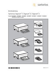
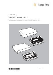
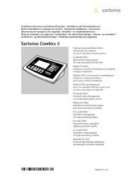
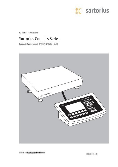
Operating Instructions<br />
<strong>Sartorius</strong> <strong>Combics</strong> Series<br />
<strong>Complete</strong> <strong>Scale</strong>s Models <strong>CAW3P</strong> | <strong>CAW3S</strong> | <strong>CAH3</strong><br />
98648-018-49
Contents<br />
Contents<br />
Notes on Using this Manual 3<br />
Warnings and Safety Precautions 4<br />
Device Description 6<br />
Intended Use 6<br />
Overview of Equipment 7<br />
Installation 8<br />
Getting Started 12<br />
Connecting Peripheral Devices or Another Platform 12<br />
Connecting an IS Weighing Platform to a <strong>Combics</strong> 3 13<br />
Connecting Peripheral Devices or a 2nd Weighing<br />
Platform: <strong>Combics</strong> 3, Model <strong>CAW3S</strong> | <strong>CAH3</strong> 14<br />
Interface Pin Assignment Chart COM1 15<br />
Connecting a PC via Interface COM1 16<br />
Interface Pin Assignment Chart COM2 17<br />
Connecting a PC via Interface COM2 18<br />
Interface Pin Assignment Chart PS2 19<br />
<strong>Scale</strong> Configuration 21<br />
Service Mode 21<br />
Entering Adjustment and Linearization Weights 32<br />
Function Allocation of the Allocation for the J Key<br />
for Calibration/Adjustment 38<br />
External Adjustment 39<br />
Internal Calibration 43<br />
Adjustment Without Weights 43<br />
Function Allocation of the J Key for Linearization<br />
and Setting/Deleting the Preload 46<br />
External Linearization 47<br />
Setting the Preload 50<br />
Clearing the Preload 51<br />
Operating Design 52<br />
Weighing Operating Design 52<br />
Menu Operating Design 58<br />
Configuration 59<br />
Setup Overview (Parameters) 63<br />
Operation 76<br />
Weighing 76<br />
Calibration, Adjustment 86<br />
Internal Adjustment for CAH Models 90<br />
SQmin Function 91<br />
Data ID Codes 94<br />
2 Operating Instructions <strong>Combics</strong> <strong>Complete</strong> <strong>Scale</strong>s<br />
Data Interfaces 96<br />
Configuring the Data Interface as a COM Port 99<br />
Data Input Format 101<br />
Data Output Format 102<br />
Configuring the Data Interface as a Printer Port 106<br />
Configuring a Printout 107<br />
GMP-compliant Printouts 108<br />
Sample Printouts 109<br />
Error Codes 115<br />
Care and Maintenance 117<br />
Service 117<br />
Repairs 117<br />
Cleaning 117<br />
Safety Inspection 118<br />
Disposal 119<br />
Specifications 120<br />
Balance Dimensions 123<br />
Accessories 125<br />
Documents List 128<br />
<strong>Sartorius</strong> Services 128<br />
Declaration of Conformity 129<br />
EC Type-approval certificate 131<br />
Test Certificate 132<br />
Plates and Markings 133<br />
Appendix: Guide to Verification<br />
of Weighing Instruments 137<br />
Explosion-risk area Zone 2 or 22 140<br />
Appendix: Passwords 145
2 Warning<br />
h<br />
Notes on Using this Manual<br />
t Please read this entire manual carefully and completely before using the device.<br />
t Read the safety precautions carefully.<br />
t This manual is part of the product. Keep it in a safe and easily accessible<br />
location.<br />
t If the manual should be lost or misplaced, please contact <strong>Sartorius</strong> for a<br />
replacement or download the latest manual from our website:<br />
www.sartorius-mechatronics.com<br />
Symbols and Signs<br />
The following symbols are used in this manual:<br />
symbol for various types of dangers.<br />
These symbols are explained in more detail in Section “Safety Instructions.“<br />
This symbol indicates useful information and tips.<br />
This symbol indicates notes on use in legal metrology within the scope of validity<br />
of Council Directive No. 90/384/EEC, replaced by 2009/23/EC<br />
(models MS...-.CE...).<br />
e, 1, This and similar symbols mean that the respective key should be pressed.<br />
T T ..., This means that this key must be pressed more than once.<br />
h<br />
t Indicates a required action<br />
y Describes the result of an action<br />
1. If a procedure has multiple steps...<br />
2. ... the steps are numbered consecutively.<br />
– Indicates an item in a list<br />
Technical advice/hotline:<br />
Phone: +49.551.308.4440<br />
Fax: +49.551.308.4449<br />
Notes on Using this Manual<br />
Operating Instructions <strong>Combics</strong> <strong>Complete</strong> <strong>Scale</strong>s 3
Warnings and Safety Precautions<br />
3 The<br />
3 If<br />
3 Make<br />
3 The<br />
3 If<br />
3 The<br />
3 Do<br />
3 Only<br />
3 The<br />
1 Do<br />
4 Operating Instructions <strong>Combics</strong> <strong>Complete</strong> <strong>Scale</strong>s<br />
Warnings and Safety Precautions<br />
<strong>Combics</strong> indicators comply with the European Council Directives as well as<br />
international regulations and standards for electrical equipment, electromagnetic<br />
compatibility, and the stipulated safety requirements. Improper use or handling can,<br />
however, result in damage and/or injury.<br />
t Read these operating instructions carefully before use.<br />
This will prevent damage to the equipment.<br />
protective conductor must not be disconnected for any reason. Use only<br />
standard cables that have protective grounding conductors.<br />
there is visible damage to the equipment or power cord: unplug the equipment<br />
and secure it against further use.<br />
absolutely sure to unplug the indicator from power before you connect or<br />
disconnect any electronic peripheral devices to or from the interface port.<br />
device should only be opened by personnel trained in accordance with <strong>Sartorius</strong><br />
guidelines.<br />
you use electrical equipment in installations and under ambient conditions<br />
requiring higher safety standards, you must comply with the provisions as specified<br />
in the applicable regulations for installation in your country.<br />
operator shall be responsible for any modifications to the equipment and for<br />
any connections of cables or equipment not supplied by <strong>Sartorius</strong> and must check<br />
and, if necessary, correct these modifications and connections.<br />
Information on operational quality is available upon request from <strong>Sartorius</strong> (in line<br />
with norms pertaining to immunity).<br />
not expose the equipment to aggressive chemical vapors or to unnecessarily<br />
extreme temperatures, moisture, shocks, or vibration.<br />
clean the device as stipulated in the cleaning instructions: Refer to the<br />
“Care and Maintenance“ chapter.<br />
display value can be affected by extreme electromagnetic influences. Once the<br />
disturbance has ceased, the instrument can be used again in accordance with its<br />
intended purpose.<br />
Danger of Explosion!<br />
not use this equipment in hazardous areas.
3 Warning<br />
3 Connect<br />
Installation<br />
when using pre-wired RS-232 connecting cables: RS-232 cables purchased<br />
from other manufacturers often have pin assignments that are incompatible with<br />
<strong>Sartorius</strong> products. Be sure to check the pin assignments against the chart in this<br />
manual before connecting the cable, and disconnect any lines identified differently<br />
from those specified by <strong>Sartorius</strong>.<br />
only <strong>Sartorius</strong> accessories and options, as these are optimally designed for<br />
use with your device. Therefore, do not use any proprietary solutions. The operator<br />
shall be solely responsible for installation and testing of any modifications to<br />
<strong>Sartorius</strong> equipment, including connection of cables or equipment not supplied<br />
by <strong>Sartorius</strong>. Information on operational quality (in line with norms pertaining to<br />
immunity) is available on request.<br />
t If you have any problems with your device, contact your local <strong>Sartorius</strong> office,<br />
dealer or service center.<br />
IP Protection Rating<br />
IP Rating – All models are rated to IP44 (with option L1: IP65)<br />
– CAWxS models are rated to IP67.<br />
– CAH1E* models: platform IP65, indicator IP69K.<br />
– CAH1G* models: platform IP67, indicator IP69K.<br />
– CAWxS models are rated to IP69K with the “I69“ option.<br />
– <strong>Complete</strong> scales with secured protective caps must be installed and tested by a<br />
certified technician.<br />
– If you install an interface port or battery connection after setting up your<br />
indicator, keep the protective cap in a safe place for future use. The cap protects<br />
the interface connector from vapors, moisture and dust or dirt.<br />
Use in Legal Metrology<br />
Warnings and Safety Precautions<br />
– When the indicator is connected to a weighing platform and this equipment is<br />
to be verified, ensure that the applicable regulations regarding verification are<br />
observed.<br />
– When connecting <strong>Sartorius</strong> weighing platforms, observe the “Guide to<br />
Verification of Weighing Instruments“ and the Declaration of Conformity with<br />
the list of permitted weighing ranges.<br />
– A sticker with the “<strong>Sartorius</strong>“ logo was affixed to the indicator as a control seal<br />
following verification. This seal will be irreparably damaged if you attempt to<br />
remove it. This will nullify the verification‘s validity. In this case, re-verification<br />
would be required in compliance with all relevant national regulations and laws.<br />
Operating Instructions <strong>Combics</strong> <strong>Complete</strong> <strong>Scale</strong>s 5
Device Description<br />
6 Operating Instructions <strong>Combics</strong> <strong>Complete</strong> <strong>Scale</strong>s<br />
Device Description<br />
<strong>Combics</strong> complete scales:<br />
– Are robust and durable, thanks to their stainless steel housing<br />
– Are easy to clean and disinfect<br />
– Are easy to operate, thanks to the following features:<br />
– Large, backlit, fully graphical dot-matrix display<br />
– Large keys with positive click action<br />
– Can be operated independently of the weighing platform location<br />
– Have a range of interfaces for flexible use<br />
– Have optional password protection for operating parameters<br />
<strong>Combics</strong> 3 speeds up your routine procedures with:<br />
– Integrated programs for applications (some can be combined):<br />
– Counting<br />
– Neutral Measurement<br />
– Averaging (animal weighing)<br />
– Weighing in percent<br />
– Checkweighing<br />
– Classification<br />
– Totalizing<br />
– Net-total Formulation<br />
– Automatic initialization when the scale is switched on<br />
– Fast response times<br />
– Automatic taring when a load is placed on the weighing platform<br />
– Designation of weight values with up to 4 lines of alphanumeric text<br />
– Can be controlled via two external computers using various protocols<br />
– Barcode scanner connection option for entering tare value or IDs (6 units)<br />
– Possibility to input tare values via the number block<br />
– LED for measurement range identification<br />
– Connection option for a second weighing platform<br />
– Alibi Memory<br />
– Internal rechargeable battery<br />
– Product data memory<br />
– Configurable printout<br />
– FlexPrint<br />
Intended use<br />
The <strong>Combics</strong> 3 is a robust complete scale for daily production and quality control in<br />
industrial applications. Any other use beyond this is considered improper.
1<br />
10<br />
<strong>CAW3P</strong><br />
19<br />
18<br />
17<br />
16<br />
15<br />
<strong>CAW3S</strong> | <strong>CAH3</strong><br />
11<br />
19<br />
17<br />
18<br />
16<br />
15<br />
PS2<br />
2<br />
3<br />
4<br />
5<br />
6<br />
7<br />
8<br />
9<br />
11<br />
12<br />
13<br />
14<br />
12<br />
20<br />
14<br />
General View of the Equipment<br />
Platform<br />
1 Level indicator<br />
2 Load plate<br />
3 Leveling feet<br />
Indicator<br />
4 10 digit keypad for entering alphanumeric values<br />
5 LEDs (for checkweighing and classification)<br />
6 Display (for details, see “Operating Design“ chapter)<br />
7 Additional function keys (see “Operating Design“)<br />
8 General function keys: Zero, Tare, Switch function, Adjustment/<br />
Calibration, Print/Data output<br />
(see “Operating Design“)<br />
9 Toggle between weighing platforms (WP)<br />
10 On/Off<br />
Rear view of indicator:<br />
Device Description<br />
11 “UNICOM“<br />
Optional:<br />
– RS-232|RS-485 or 422 interface, e.g. for:<br />
– PC connection<br />
– Printer connection<br />
– Digital I/O<br />
– 4 to 20 mA<br />
– Profibus DP<br />
– Ethernet TCP/IP|ModBus TCP<br />
12 RS-232 interface “COM1“<br />
e.g. for:<br />
– PC connection<br />
– Printer connection<br />
– Digital input<br />
– Stop light output<br />
13 “PS2“ e.g. for:<br />
– Keyboard connection<br />
– Barcode scanner connection<br />
14 Power cord with country-specific plug<br />
15 Input for menu access switch (standard or legal-for-trade mode)<br />
for WP 1<br />
16 Weighing platform WP 1 connection<br />
for analog scales,<br />
optional for “xBPI“|“SBI“ scales<br />
17 Weighing platform WP 2 connection,<br />
optional for analog scales or “xBPI“|“SBI“ scales<br />
18 Input for menu access switch (standard or legal-for-trade mode)<br />
for WP 2<br />
19 RS-232 interface “COM2“<br />
e.g. for:<br />
– PC connection<br />
– Printer connection<br />
20 Vent valve: 1.5 Nm<br />
Operating Instructions <strong>Combics</strong> <strong>Complete</strong> <strong>Scale</strong>s 7
Installation<br />
3 Once<br />
3 If<br />
3 Suspension<br />
8 Operating Instructions <strong>Combics</strong> <strong>Complete</strong> <strong>Scale</strong>s<br />
Installation<br />
When a <strong>Combics</strong> indicator is ordered with special equipment, the desired options<br />
come pre-loaded from the factory.<br />
Storage and Shipping Conditions<br />
the equipment has been removed from the packaging, it may lose accuracy if<br />
subjected to strong vibration.<br />
the load plate is lifted using a vacuum lifting pad, gloves, safety shoes and safety<br />
gear must be worn. Risk of injury!<br />
This work may only be carried out by reliable and authorized personnel.<br />
points are provided for weighing platforms with an overall size of<br />
1 + 1 m or larger. Do not step under the load during weighing platform/load plate<br />
transport or when lifting. Corresponding accident prevention regulations must be<br />
followed.<br />
Do not damage the clamp boxes and load receptors during transport.<br />
– Do not expose the equipment to unnecessarily extreme temperatures, moisture,<br />
shocks, blows or vibration.<br />
– Permissible storage temperature: –10°C to +40°C<br />
Installation Location<br />
Avoid adverse influences at the place of installation:<br />
– Extreme temperatures (operating temperature: –10°C to +40°C)<br />
– Aggressive chemical vapors<br />
– Extreme moisture (according to IP protection class)<br />
Unpacking<br />
For devices with a platform size of 60 x 80 cm or larger:<br />
t Protective gear must be worn (safety shoes and if required, gloves)<br />
t Always lift on the side walls when lifting or transporting the weighing platform.<br />
t After unpacking the device, check it for any visible damage as a result of rough<br />
handling during shipment.<br />
y If you detect any damage, proceed as directed in the chapter entitled “Care and<br />
Maintenance“ under “Safety Inspection.“<br />
t Save the original packaging for any future transport.<br />
Unplug all connected cables before packing the equipment.<br />
Checking Package Contents<br />
– Indicator<br />
– Weighing platform<br />
– Operating instructions<br />
– Options (special accessories) as listed on the bill of delivery
<strong>CAH3</strong> models: Remove transport locks<br />
Installation<br />
t Place the weighing platform at its installation location, remove the<br />
weighing pan.<br />
t Remove the transport lock: Remove screw 1<br />
t Loosen screw 2.<br />
t Turn the mounting bracket 180° and re-secure screw 2.<br />
t Re-attach screw 1 to the lever<br />
3 The transport lock must be re-installed before transporting the weighing platform.<br />
Leveling the Weighing Platform<br />
The weighing platform must be exactly level to ensure reproducible weighing results<br />
every time. Therefore, the weighing platform must always be re-leveled after it has<br />
been moved to a different location.<br />
t Remove the weighing pan.<br />
t Loosen the lock nuts using a wrench (SW17).<br />
t Use a SW5 Allen key to screw the leveling feet in/out.<br />
Turning the leveling feet clockwise lifts the weighing platform,<br />
turning the leveling feet counterclockwise lowers the weighing platform.<br />
Operating Instructions <strong>Combics</strong> <strong>Complete</strong> <strong>Scale</strong>s 9
Installation<br />
10 Operating Instructions <strong>Combics</strong> <strong>Complete</strong> <strong>Scale</strong>s<br />
t Align the weighing platform leveling feet so that air bubble is centered within<br />
the circle of the level indicator.<br />
t Check to ensure that all four leveling feet rest securely on the work surface.<br />
y Each of the leveling feet must support an equal load.<br />
t Re-fasten the lock nuts after leveling:<br />
Small platforms (1 measuring cell) counter to the platform frame,<br />
large platforms (4 measuring cells) counter to the platform foot.<br />
t Place the weighing pan on the scale.<br />
Operating Limits<br />
You should not exceed the highest load for weighing platforms.<br />
The highest capacity for the weighing platform is as follows depending on the load<br />
used (center, side, one-sided corner load):<br />
Platform size Center Side Corner<br />
320 + 240 50 35 20<br />
400 + 300 130 85 45<br />
500 + 400 300 200 100<br />
500 + 400 P* 600 400 200<br />
650 + 500 S** 450 300 150<br />
800 + 600 P* 1200 800 400<br />
800 + 600 S** 900 600 300<br />
800 + 800 4500 3000 1500<br />
1000 + 800 4500 3000 1500<br />
1000 + 1000 4500 3000 1500<br />
1250 + 1000 4500 3000 1500<br />
1500 + 1250 4500 3000 1500<br />
1500 + 1500 4500 3000 1500<br />
2000 + 1500 4500 3000 1500<br />
* Steel<br />
** Stainless steel<br />
For CAH* models Platform size Supported load (center) in kg<br />
400 + 300 130<br />
560 + 450 130<br />
800 + 600 600
3 Superstructures<br />
Shock Resistance<br />
The weighing platform has a robust design; however, falling weighing samples, side<br />
impacts and shocks should be avoided. The weighing platform can withstand loads<br />
specified in the DIN standard IEC68 Part 2-27.<br />
Notes on Planning Superstructures<br />
must be completely attached before the weighing platform is<br />
connected to the power.<br />
The weighing platform is designed for system integration. <strong>Scale</strong> drawings are the<br />
basis for the selection of the required superstructures. The fixing of model CAH*IG*<br />
weighing platforms should be carried out using the YAS04IS fastening kit.<br />
Moving or rotating parts on the weighing pan must be designed so that the<br />
weighing results are not influenced. Rotating parts should be counterbalanced, for<br />
example.<br />
The weighing pan must be free on all sides so that there is no connection between<br />
the weighing platform and fixed parts due to falling parts or dirt. Cables and hoses<br />
between the weighing platform and other devices may not exert any forces on the<br />
weighing platform. These cables may not touch the weighing pan.<br />
When setting up systems in hazardous areas (Zone 2 or 22), any relevant<br />
specifications should be observed, e. g.: EN60079-14.<br />
The design should ensure that moving parts do not cause electrostatic discharges<br />
(e.g. roller conveyors).<br />
Preload Range (Zero Set Range)<br />
The weight of the superstructures that are attached to the weighing platform is<br />
designated as a “preload.“ The preload is electronically compensated for in the<br />
weighing platform so that the full weighing range remains available and thus<br />
zeroing and/or adjustment (with external weights) is possible.<br />
Greater preloads reduce the weighing capacity. You may not fall below the following<br />
weighing range values:<br />
– For CAH*E-16ED... and CAH*E-32ED... a min. 20 kg weighing range must be<br />
maintained<br />
– For CAH*E-64ED... and CAH*G-64FE... a min. 35 kg weighing range must be<br />
maintained<br />
– For CAH*G-150IG-H and CAH*G-300IG-H a min. 60 kg weighing range must be<br />
maintained<br />
The preload must always be set before verification.<br />
Acclimatizing the Device<br />
Installation<br />
Condensation can form on the surfaces of a cold device when it is brought into a<br />
substantially warmer area.<br />
t Allow the device to acclimatize for about 2 hours at room temperature, leaving<br />
it unplugged from AC power.<br />
Operating Instructions <strong>Combics</strong> <strong>Complete</strong> <strong>Scale</strong>s 11
Getting Started<br />
Getting Started<br />
Steps 1.) Set up the weighing platform with the indicator.<br />
2.) Level the weighing platform<br />
3.) Connect peripheral devices, e.g. printer to the COM1 or UNICOM interface:<br />
see Data Interfaces chapter starting on page 99<br />
4.) Connecting the device to AC power<br />
5.) Carry out an alignment: for adjustment, see page 27, for linearization see page 24<br />
3 The<br />
3 Peripheral<br />
Connecting Peripheral Devices or Another Weighing<br />
Platform<br />
An analog <strong>Sartorius</strong> platform (CAPP, CAPS) or an IS weighing platform is connected<br />
at the factory to the <strong>Combics</strong> indicator WP1 input.<br />
load cell should be connected by a certified technician who has received<br />
specialized training from <strong>Sartorius</strong>. Any installation work that does not conform<br />
to the instructions in this manual results in forfeiture of all claims under the<br />
manufacturer’s warranty.<br />
devices should be connected by a certified technician who has received<br />
specialized training from <strong>Sartorius</strong>. Any installation work that does not conform<br />
to the instructions in this manual results in forfeiture of all claims under the<br />
manufacturer’s warranty.<br />
3 Disconnect the equipment from the power supply before starting connection work.<br />
t Place cables from peripheral devices next to the indicator.<br />
<strong>CAW3S</strong>, <strong>CAH3</strong> (IP69K) t Opening the <strong>Combics</strong> indicator:<br />
Loosen the ten cap nuts on the front panel. Remove the front panel.<br />
3 The<br />
12 Operating Instructions <strong>Combics</strong> <strong>Complete</strong> <strong>Scale</strong>s<br />
Installing Connection and Interface Cables<br />
cable gland (IP69K protection) is pre-mounted on the indicator. Please use<br />
extreme caution when performing any work on the equipment that affects this<br />
cable gland.<br />
You must use a torque wrench. The torque for this cable gland is 5 Nm.<br />
Preparing Cables<br />
t Strip approx. 14 cm from the end of the cable.<br />
t Shorten the shielding to approx. 2 cm and pull back over the insulation.<br />
t Strip approximately 5 mm of the insulation from the wires of the connecting<br />
cable and affix ferrules to the wire ends.
2<br />
1 5<br />
3<br />
3 Please<br />
4<br />
Attaching the Cable Entry<br />
use extreme caution when performing any work on the equipment that<br />
affects this cable gland.<br />
You must use a torque wrench.<br />
The torque for this cable gland is 5 Nm.<br />
t Remove the protective cap from the bore hole on the indicator.<br />
t Insert the included cable gland through the bore hole and secure from the inside<br />
using the locknut (1).<br />
t Insert the cable through the cable gland until the shielding (2) comes into<br />
contact with the clamps (3). Tighten the screw-down nut (4) until the gasket (5)<br />
inserted between the screw-down nut and cable forms a small beaded rim.<br />
t Check the shielding and clamps.<br />
t Securely connect the wires of the connecting cable in accordance with the<br />
terminal assignments.<br />
t After you close the housing again, use a pressure gauge to check the integrity of<br />
the IP69K protection. For details, contact the <strong>Sartorius</strong> Service Center.<br />
Connecting Cables<br />
t Insert all cable wires through the ferrite case, wind them around the ferrite case<br />
and then reinsert back through the ferrite case.<br />
t Screw the wires tightly into the clamps.<br />
See the following pages for terminal pin allocation<br />
t Refer to the data sheet or operating instructions of the<br />
weighing platform for details on the assignment of wire<br />
colors/signals. Ensure any lines that are not assigned<br />
are insulated correctly.<br />
t When connecting a load receptor that uses 4-conductor technology (the cable<br />
of the weighing platform to be connected only has 4 lines), connect clamp<br />
pairs 1 and 2 (EXC+ und SENSE+), and 5 and 6 (SENSE- und EXC-) with a wire<br />
jumper.<br />
Connecting an IS Weighing Platform to a <strong>Combics</strong> 3<br />
You can connect an IS weighing platform to WP2.<br />
Getting Started<br />
Features – IS weighing platforms process weighing data independently of the indicator.<br />
– Internal adjustment option<br />
– IS...-0CE models: have a separate approval number, printed on a tag that is<br />
affixed to the cable.<br />
– Please observe the conditions described in the manual for the weighing platform<br />
you connect.<br />
Operating Instructions <strong>Combics</strong> <strong>Complete</strong> <strong>Scale</strong>s 13
Getting Started<br />
PS2 COM1 COM2 A8<br />
LED + Display<br />
Keypad<br />
Weighing platform<br />
Interface 2<br />
14 Operating Instructions <strong>Combics</strong> <strong>Complete</strong> <strong>Scale</strong>s<br />
Connecting Peripheral Devices or a 2nd Weighing<br />
Platform: <strong>Combics</strong> 3, Model type <strong>CAW3S</strong> | <strong>CAH3</strong><br />
Digital PCB<br />
COM1, COM2 and PS2 terminal assignments (applies to all PCBs)<br />
PS2<br />
1 LOAD_PRINTER 11 Clear to send (CTS) 21 5 V switched<br />
2 RESET_OUT 12 Data terminal ready (DTR) 22 PS/2_data<br />
3 GND 13 Data input (RXD) 23 PS/2_clock<br />
4 GND 14 Data output (TXD) 24 GND<br />
5 5V_OUT 15 GND COM2<br />
6 5V switched 16 Universal In 31 CTS_COM2<br />
7 GND 17 Control output: “lower“ 32 DTR_COM2<br />
8 GND 18 Control output: “equal“ 33 RXD_COM2<br />
9 n.c. 19 Control output: “heavier“ 34 TXD_COM2<br />
10 LINE_OUT 20 Control output: “set“ 35 GND<br />
36 GND<br />
A8 terminal assignments<br />
1 EXC+ Bridge supply voltage (+)<br />
2 SENSE+ Sense (+) for bridge supply voltage<br />
3 OUT+ Measuring voltage positive<br />
4 OUT- Measuring voltage negative<br />
5 SENSE- Sense (-) for bridge supply voltage<br />
6 EXC- Bridge supply voltage (–)<br />
Keys<br />
LED + Display<br />
PS2 COM1 COM2 A6/7<br />
Interface PCB for RS-232/485 for IS weighing platform<br />
(option A6/A7)<br />
LED + Display<br />
PS2 COM1 COM2<br />
LED + Display<br />
Tastatur<br />
Keypad<br />
Weighing platform<br />
Interface 1<br />
A20<br />
A6/7 terminal assignments<br />
1 CTS 11 TxD/RxD+<br />
2 DTR 12 TxD/RxD-<br />
3 RxD 13 LINE_OUT<br />
4 TxD 14 LINE_OUT<br />
5 GND 15 GND<br />
6 Adjustment Lock 16 GND<br />
Keys<br />
LED + Display<br />
Interface PCB for ADC 10.000e (option A20)<br />
A20 terminal assignments<br />
1 EXC+<br />
2 SENSE+<br />
3 OUT+<br />
4 OUT-<br />
5 SENSE-<br />
6 EXC-<br />
Keys<br />
LED + Display
PS2 COM1 COM2<br />
LED + Display<br />
Keypad<br />
Weighing platform<br />
Interface 1<br />
A62/72<br />
Interface PCB for RS-232/485 for IS weighing platform<br />
(option A62/A72)<br />
Interface PCB A6/7 and A62/72<br />
1 CTS 11 TxD/RxD+<br />
2 DTR 12 TxD/RxD-<br />
3 RxD 13 LINE_OUT<br />
4 TxD 14 LINE_OUT<br />
5 GND 15 GND<br />
6 Adjustment Lock 16 GND<br />
Keys<br />
LED + Display<br />
Interface Pin Assignment Chart COM1<br />
Model type <strong>CAW3P</strong> (IP44 protection)<br />
Getting Started<br />
COM1 female connectors:<br />
25-pin D-Submini female connector (DB25S) with screw lock hardware for cable<br />
gland<br />
Recommended interface connector:<br />
25-pin D-Submini (DB25) with shielded cable clamp assembly and shield plate<br />
(Amp type 826 985-1C) and fastening screws (Amp type 164868-1)<br />
COM1 pin assignments<br />
Pin 1: Shield<br />
Pin 2: Data output (TxD)<br />
Pin 3: Data input (RxD)<br />
Pin 4: GNO<br />
Pin 5: Clear to send (CTS)<br />
Pin 6: Not assigned<br />
Pin 7: Internal ground (GND)<br />
Pin 8: Internal ground (GND)<br />
Pin 9: Not assigned<br />
Pin 10: Not assigned<br />
Pin 11: +12V for printer<br />
Pin 12: RES_OUT\<br />
Pin 13: +5 V switch<br />
Pin 14: Internal ground (GND)<br />
Pin 15: Universal switch<br />
Pin 16: Control output: “lower“<br />
Pin 17: Control output: “equal“<br />
Pin 18: Control output: “heavier“<br />
Pin 19: Control output: “set“<br />
Pin 20: Data terminal ready (DTR)<br />
Pin 21: Ground power supply (GND)<br />
Pin 22: Not assigned<br />
Pin 23: Not assigned<br />
Pin 24: Power supply +15..25 V (peripherals)<br />
Pin 25: +5 V<br />
Operating Instructions <strong>Combics</strong> <strong>Complete</strong> <strong>Scale</strong>s 15
Getting Started<br />
Connecting a PC via Interface COM1<br />
Use the following cables to connect a PC to the indicator in accordance with the<br />
RS-232C/V24 standard (max. cable length 15 m):<br />
Model type <strong>CAW3P</strong>: connecting cable 7357312<br />
Model type <strong>CAW3S</strong> | <strong>CAH3</strong>: connecting cable YCC02-D09F6<br />
Pin assignment<br />
RS232<br />
Pin assignments for the cable from the indicator to an RS-232 PC interface (COM1).<br />
Indicator side PC side<br />
Model type <strong>CAW3P</strong> DSUB connector<br />
25-pin D-Sub male connector 9-pin or 25-pin<br />
1<br />
Sgn GND 7 5 GND 7 GND<br />
TxD 2 2 RxD 3 RxD<br />
RxD 3 3 TxD 2 TxD<br />
DTR 20 8 CTS 5 CTS<br />
CTS 5 4 DTR 20 DTR<br />
Model type <strong>CAW3S</strong> | <strong>CAH3</strong><br />
Open cable end DSUB connector<br />
9-pin or 25-pin<br />
Sgn GND 15 5 GND 7 GND<br />
TxD 14 2 RxD 3 RxD<br />
RxD 13 3 TxD 2 TxD<br />
DTR 12 8 CTS 5 CTS<br />
CTS 11 4 DTR 20 DTR<br />
16 Operating Instructions <strong>Combics</strong> <strong>Complete</strong> <strong>Scale</strong>s
5 1<br />
9<br />
6<br />
Interface Pin Assignment Chart COM2<br />
Model type <strong>CAW3P</strong> (IP44 protection)<br />
Getting Started<br />
COM1 female connectors:<br />
25-pin D-Submini female connector (DB25S) with screw lock hardware for cable<br />
gland<br />
Recommended interface connector:<br />
25-pin D-Submini (DB25) with shielded cable clamp assembly and shield plate<br />
(Amp type 826 985-1C) and fastening screws (Amp type 164868-1)<br />
COM1 pin assignments<br />
Pin 1: Shield<br />
Pin 2: Data output (TxD)<br />
Pin 3: Data input (RxD)<br />
Pin 4: GNO<br />
Pin 5: Clear to send (CTS)<br />
Pin 6: Not assigned<br />
Pin 7: Internal ground (GND)<br />
Pin 8: Internal ground (GND)<br />
Pin 9: Not assigned<br />
Pin 10: Not assigned<br />
Pin 11: +12 V for printer<br />
Pin 12: RES_OUT\<br />
Pin 13: +5 V switch<br />
Pin 14: Internal ground (GND)<br />
Pin 15: Universal switch<br />
Pin 16: Control output: “lower“<br />
Pin 17: Control output: “equal“<br />
Pin 18: Control output: “heavier“<br />
Pin 19: Control output: “set“<br />
Pin 20: Data terminal ready (DTR)<br />
Pin 21: Ground power supply (GND)<br />
Pin 22: Not assigned<br />
Pin 23: Not assigned<br />
Pin 24: Power supply +15..25 V (peripherals)<br />
Pin 25: +5 V<br />
Operating Instructions <strong>Combics</strong> <strong>Complete</strong> <strong>Scale</strong>s 17
Getting Started<br />
Connecting a PC via Interface COM2<br />
Use the following cables to connect a PC to the indicator in accordance with the<br />
RS-232C/V24 standard (max. cable length 15 m):<br />
Model type <strong>CAW3P</strong>: connecting cable 7357312<br />
Model type <strong>CAW3S</strong> | <strong>CAH3</strong>: connecting cable YCC02-D09F6<br />
Pin assignment<br />
RS232<br />
Pin assignments for the cable from the indicator to an RS-232 PC interface (COM1).<br />
Indicator side PC side<br />
Model type <strong>CAW3P</strong> DSUB connector<br />
25-pin D-Sub male connector 9-pin or 25-pin<br />
1<br />
Sgn GND 7 5 GND 7 GND<br />
TxD 2 2 RxD 3 RxD<br />
RxD 3 3 TxD 2 TxD<br />
DTR 20 8 CTS 5 CTS<br />
CTS 5 4 DTR 20 DTR<br />
Model type <strong>CAW3S</strong> | <strong>CAH3</strong><br />
Open cable end DSUB connector<br />
9-pin or 25-pin<br />
Sgn GND 15 5 GND 7 GND<br />
TxD 14 2 RxD 3 RxD<br />
RxD 13 3 TxD 2 TxD<br />
DTR 12 8 CTS 5 CTS<br />
CTS 11 4 DTR 20 DTR<br />
18 Operating Instructions <strong>Combics</strong> <strong>Complete</strong> <strong>Scale</strong>s
6 5<br />
4<br />
2<br />
3<br />
1<br />
Interface Pin Assignment Chart PS2<br />
Model type CAISL (IP44 protection)<br />
PS2 female connector:<br />
6-pin miniature socket PS2 (Mini-DIN)<br />
Recommended interface connector:<br />
6-pin miniature socket PS2 with integrated shielded cable clamp assembly<br />
Pin assignment:<br />
Pin 1: Keyboard data (data interface cable)<br />
Pin 2: Not assigned<br />
Pin 3: Internal ground (GND)<br />
Pin 4: +5V switched<br />
Pin 5: Keyboard clock<br />
Pin 6: Not used<br />
Connecting a Bar Code Scanner<br />
Accessory YBR02CISL<br />
t Disconnect the indicator from AC power (unplug the AC adapter)<br />
For <strong>CAW3P</strong> models:<br />
t Connect the barcode scanner via PS/2.<br />
Getting Started<br />
For <strong>CAW3S</strong> | <strong>CAH3</strong> models:<br />
t Pin assignment, see “Connecting Peripheral Devices“ (implemented via the<br />
YCC02-BR02 connecting cable or as option M8) on page 14.<br />
NOTE: This equipment has been tested and found to comply with the limits pursuant<br />
to part 15 of FCC Rules. These limits are designed to provide reasonable<br />
protection against harmful interference. This equipment generates, uses and can<br />
radiate radio frequency energy and, if not installed and used in accordance with<br />
these instructions, may cause harmful interference to radio communications. For<br />
information on the specific limits and class of this equipment, please refer to the<br />
Declaration of Conformity. Depending on the particular class, you are either required<br />
or requested to correct the interference. If you have a Class A digital device, you<br />
need to comply with the FCC statement as follows: “Operation of this equipment in<br />
a residential area is likely to cause harmful interference in which case the user will be<br />
required to correct the interference at his own expense.“<br />
Operating Instructions <strong>Combics</strong> <strong>Complete</strong> <strong>Scale</strong>s 19
Getting Started<br />
3 The<br />
3 If<br />
20 Operating Instructions <strong>Combics</strong> <strong>Complete</strong> <strong>Scale</strong>s<br />
Closing the <strong>Combics</strong> Indicator<br />
t Re-attach the front panel and secure it with the ten cap nuts ( 1Nm ).<br />
Connecting the Device to AC Power<br />
The indicator is powered through the pre-installed power cord. The power supply is<br />
integrated into the indicator. The device can be operated with a supply voltage of<br />
100 V to 240 V.<br />
power connection must be made in accordance with the regulations applicable<br />
in your country.<br />
The printed voltage rating (see type label) must match the voltage in the place of<br />
installation. If the voltage specified on the label or the plug design of the AC adapter<br />
do not match the rating or standard you use, please contact your <strong>Sartorius</strong> office or<br />
dealer.<br />
t Check the voltage rating and plug design.<br />
t The device must be plugged into a properly installed wall outlet.<br />
Protection Class 1 Device<br />
t The device must be plugged into a properly installed wall outlet which has a<br />
protective grounding conductor (PE).<br />
Safety Precautions<br />
you use an electrical outlet that does not have a protective grounding conductor,<br />
ensure that an equivalent protective conductor is installed by a certified electrician<br />
(as specified in the applicable regulations for installation in your country).<br />
The protective effect must not be negated by using an extension cord without a<br />
protective grounding conductor.<br />
Before using for the first time, any superstructure parts must be completely installed.<br />
Avoid connecting the equipment to lines that have a heavy electrical load,<br />
e.g. compressors, large machinery, etc.<br />
Warm-up Time<br />
To deliver exact results, the device must warm up for at least 30 minutes after<br />
connection to AC power. Only after this time will the device have reached the<br />
required operating temperature.<br />
Using a Verified Device in Legal Metrology<br />
Ensure that there is a warm-up time of at least 24 hours after connection to the<br />
power supply.
Configuring Weighing Platforms<br />
Service-Mode<br />
Purpose The Service mode enables access to additional menu items in the Setup menu<br />
which are not displayed when the Service mode is not active. The most important<br />
calibration and adjustment work for the indicator and for the connected weighing<br />
platform can be carried out in the Service menu, e.g. ADC configuration.<br />
When the Service mode is active, an “S” is shown in the top right-hand corner of<br />
the display. To deactivate the Service mode, restart the indicator (turn the indicator<br />
off and back on again).<br />
Activating the Service Mode<br />
t Press e to turn on the device.<br />
y When turned on the scale is in an application program.<br />
t Enter the service password (see Appendix General User Password) and press<br />
M to confirm.<br />
y The device in now is Service mode. An “S“ appears in the top right-hand<br />
corner of the display.<br />
t Press the “q“ soft key several times to select the “Device<br />
parameters“ line.<br />
t Press the “O“ soft key.<br />
y The “Device“ submenu will open.<br />
t Select and open the corresponding submenu. Repeat this procedure until the<br />
desired menu item in the lowest menu level can be opened.<br />
t View or change the menu item (confirm with “l“) and use “o“ to return to the<br />
previous menu.<br />
t Press M or “oo“ to exit the Setup menu.<br />
Exiting Service Mode<br />
Configuring Weighing Platforms<br />
Turn the device off and then on again to return to the normal application mode.<br />
If you exit the Setup menu without changing settings by confirming with M or<br />
the “oo“ soft key, the Service mode will remain active. Press the M key to<br />
re-open the Setup menu.<br />
Operating Instructions <strong>Combics</strong> <strong>Complete</strong> <strong>Scale</strong>s 21
Configuring Weighing Platforms<br />
Overview of the Setup Menu in Service Mode<br />
o = Factory setting<br />
x = User-defined setting<br />
Service password entry Setup Application parameters, please refer to the “Basic Application Programs” manual<br />
Fn key “Setup Overview (Parameters)“<br />
Device parameters<br />
Info, see the “Setup Overview (Parameters)“ section<br />
Language, see the “Setup Overview (Parameters)“ section<br />
Setup access with service password<br />
Device parameters<br />
WP1<br />
RS-232 1 )<br />
SBI standard<br />
SBI verifiable<br />
o IS-232<br />
ADC-232<br />
RS-485 1 ) o IS-485<br />
ADC-485<br />
Internal<br />
ADC configuration (see the “Setup Menu for ADC Configuration“ section)<br />
Calibration/Adjustment<br />
CAL key function<br />
o Ext. cal./adj.; factory-def. wt.<br />
Ext. cal./adjust.; user-defined weight<br />
Ext. lineariz.; factory-def. wts<br />
Ext. lineariz.; user-def. wts<br />
Set preload<br />
Delete preload<br />
Key blocked<br />
Cal./adj. sequence<br />
isoCAL function 3 )<br />
1 ) Equipment version: – then blocked internally<br />
2 ) Not available on devices verified for use in legal metrology<br />
3 ) Only when operated with <strong>Sartorius</strong> IS weighing platforms or an external ADC<br />
22 Operating Instructions <strong>Combics</strong> <strong>Complete</strong> <strong>Scale</strong>s<br />
Cal. then auto adjust<br />
o Cal. then manual adjust<br />
o Off<br />
Adjustment prompt<br />
Activate external adjustment 2 )<br />
o Activated<br />
Deactivated<br />
Parameter for external weight<br />
Cal./adj. weight:<br />
Lin. weight 1...4:<br />
Adjust without weights 2 ) Input parameters<br />
Geographical data 2 )<br />
Save parameters<br />
Input parameters<br />
Save parameters<br />
Nominal load:<br />
Resolution:<br />
Sensitivity 1…4:<br />
Yes<br />
o No<br />
Geographical latitude<br />
Altitude<br />
Gravitational acceleration<br />
Yes<br />
o No
Device Parameters<br />
WP1<br />
Internal Calibration/Adjustment unit<br />
Grams /g<br />
Kilograms /kg<br />
Tons /t<br />
o Pounds /lb<br />
Menu items “Adapt filter“ - “Factory settings: only bal. func,“<br />
see the “Setup Overview (Parameters)“ section<br />
Off<br />
COM-1 (when the WP is assigned to this interface)<br />
COM-2 (when the WP is assigned to this interface)<br />
UNICOM (only if available)<br />
WP2, see the “Setup Overview (Parameters)“ section<br />
RS-232 1 ) similar to “Internal“ menu for WP1<br />
RS-485 1 ) similar to “Internal“ menu for WP1<br />
o Off<br />
COM-1 similar to WP 1<br />
COM-2 similar to WP 1<br />
COM-1, see the “Setup Overview (Parameters)“ section<br />
COM-2, see the “Setup Overview (Parameters)“ section<br />
“Control I/O ports“ - “Terminal data,“ see the “Setup Overview (Parameters)“ section<br />
SQmin<br />
SQmin input<br />
Display<br />
GMP print<br />
Alibi memory 2 )<br />
Clear alibi memory<br />
1 ) Equipment version: – then saved internally<br />
2 ) Only if alibi memory is available (option)<br />
Alibi memory period<br />
SQmin WP1<br />
SQmin WP2<br />
SQmin WP3<br />
No<br />
o Yes<br />
o No<br />
Yes<br />
Yes<br />
o No<br />
In days 90<br />
SQmin WP1 0.000 kg<br />
SQmin WP2 0.000 kg<br />
SQmin WP3 0.000 kg<br />
Configuring Weighing Platforms<br />
Operating Instructions <strong>Combics</strong> <strong>Complete</strong> <strong>Scale</strong>s 23
Configuring Weighing Platforms<br />
Setup Menu for A/D Converter Configuration<br />
Setup access in Service mode<br />
WP1 – Internal – ADC configuration<br />
Standard configuration Ranges Single-range mode <strong>Scale</strong> interval d<br />
Max. cap.<br />
Available units User-definable /o<br />
Grams /g<br />
Kilograms /kg<br />
Carats /ct<br />
...<br />
Save parameters Yes<br />
oNo<br />
oVerifiable Accuracy Class III/IIII<br />
configuration class<br />
Ranges Single-range mode<br />
24 Operating Instructions <strong>Combics</strong> <strong>Complete</strong> <strong>Scale</strong>s<br />
Available units<br />
Save parameters<br />
Multi-interval mode<br />
Multi-interval mode<br />
User-definable /o<br />
oGrams /g<br />
oKilograms /kg<br />
...<br />
Yes<br />
oNo<br />
Multi-interval mode <strong>Scale</strong> interval d<br />
Range 1<br />
Range 2<br />
Range 3<br />
Max. cap.<br />
Multiple-range <strong>Scale</strong> interval d<br />
mode Range 1<br />
Range 2<br />
Range 3<br />
Max. cap.<br />
D:<br />
E:<br />
Min. capacity:<br />
Max. cap.:<br />
D:<br />
E:<br />
Min. capacity:<br />
Range 1:<br />
Range 2<br />
Range 3:<br />
Max. cap.:<br />
D:<br />
E:<br />
Min. capacity:<br />
Range 1:<br />
Range 2<br />
Range 3:<br />
Max. cap.:
Analog/Digital Converter (ADC)<br />
Purpose Adjust the parameters of the analog/digital converter to the connected load cell or<br />
weighing platform. After ADC configuration, the ADC in connection with the load<br />
sensor is defined as a scale.<br />
3 Once<br />
the ADC configuration has been locked, the indicator can no longer be used<br />
to influence weighing results. The scope of functions available in the weighing<br />
instrument is defined by the A/D converter. Weighing functions that can be<br />
activated include reading weight values, taring, adjustment, reading the tare value,<br />
saving/deleting the tare entry.<br />
Setup Information – ADC configuration is only possible when the menu access switch is open.<br />
Re-close the menu access switch after ADC configuration.<br />
– Before ADC configuration, you must first set whether or not the weighing<br />
platform will be used as a standard or verifiable weighing platform.<br />
– ADC configuration is carried out in the Service mode in the Setup menu under<br />
“WP 1“ for the first weighing platform and “WP 2“ for the second.<br />
– Entries made in ADC configuration will not be affected by a menu reset<br />
(returning the setup parameters to their factory settings).<br />
See also the overview in the “Setup Menu for A/D Converter Configuration“ section.<br />
Setting Parameters for ADC Configuration<br />
Configuring Weighing Platforms<br />
Standard or Verifiable Configurations In ADC configuration, you must first select whether the weighing platform should<br />
be configured as a standard or verifiable (for use in legal metrology) weighing<br />
platform.<br />
– Standard configuration “Standard“<br />
– Verifiable configuration “Verifi able“<br />
Select using the “Q“ or “q“ soft key. Press the “O“ soft key to confirm the setting<br />
and open the Configuration menu.<br />
Accuracy Class This menu item is not shown when the Standard configuration is active. When<br />
the Verifiable configuration is active (for weighing platforms verified or verifiable<br />
for use in legal metrology), only Class l/m can be selected. Activate the<br />
“Accuracy class“ menu item, select “Class III/IIII“ and<br />
confirm your selection using the “l“ soft key.<br />
Ranges The capacity of the weighing platform can be divided into multiple ranges:<br />
– “ Single-range mode“:<br />
The entire weighing range is divided into scale intervals on the basis of the<br />
lowest interval d and the maximum load.<br />
– “ Multi-interval mode“:<br />
The “Multi-interval mode” function divides the weighing capacity into as<br />
many as four ranges, each with a different readability. Corresponding changes<br />
take place automatically. Once the scale has been tared, the highest possible<br />
resolution is available even if the weighing platform is loaded with a higher<br />
weight. This is only permitted in the accuracy classes l/m for the verifiable<br />
configuration.<br />
– “ Multiple-range mode“:<br />
Multiple-range mode has two or three weighing ranges. When the range limit<br />
is exceeded, the scale switches into the next highest weighing range (lower<br />
resolution) and remains there. The scale can be returned to the lower weighing<br />
range (higher resolution) only by pressing the ( key and then unloading the<br />
scale.<br />
Operating Instructions <strong>Combics</strong> <strong>Complete</strong> <strong>Scale</strong>s 25
Configuring Weighing Platforms<br />
Select the desired configuration using the “Q“ or “q“ soft key. Confirm your<br />
selection using the “O“ key. Make additional settings in the submenu: scale interval<br />
d/verification scale interval e, minimum load (Verifiable configuration only),<br />
range limits (Multi-interval or Multiple range mode only) and maximum capacity.<br />
Confirm using the “l“ soft key or cancel using “Esc.“<br />
<strong>Scale</strong> Interval d <strong>Scale</strong> interval d indicates the resolution of the weighing instrument.<br />
The scale interval d can be entered only in increments of 1, 2, 5, 10, 20, etc.<br />
When using verifiable or verified weighing platforms, the scale interval d is the same<br />
as the verification scale interval e.<br />
Verification <strong>Scale</strong> Interval e The verification scale interval e indicates the resolution of the weighing instrument<br />
in legal metrology. The verification scale interval e can be entered only in<br />
increments of 1, 2, 5, 10, 20, etc. For weighing instruments of accuracy class l or<br />
m, e = d. This is why the scale interval d does not need to be entered separately.<br />
When “Standard configuration” is used, this menu item is not displayed.<br />
Minimum Capacity (Min. Cap.) When “Standard configuration” is used, this menu item is not displayed. The<br />
minimum load of the connected weighing platform is entered under this menu item.<br />
The minimum load for scales of accuracy class l is 20 e and 10 e for class m.<br />
Important Note: The function of the minimum load setting is to warn operators that below this<br />
limit, the summation of tolerances might lead to significant measurement errors. In<br />
Germany, for example, initial weights below the minimum load are not allowed.<br />
Maximum Capacity (Max. Cap.) The maximum capacity is the maximum load that may be placed on the weighing<br />
instrument. When heavier weights are used the weighing instrument displays<br />
overload “H.” The scale intervals of the weighing instrument are calculated using<br />
the maximum load and the scale interval d (e.g. max. capacity = 15.000 kg, smallest<br />
scale interval d = 0.005 kg yields 3000 scale intervals).<br />
In legal metrology the total number of intervals must be no more than 3000 e, and<br />
when using multi-interval scales there must not be more than 3000 e intervals per<br />
range.<br />
In standard operation, as opposed to legal metrology, you can define a “Super<br />
Range” weighing instrument of over 3000 intervals. These parameters, however,<br />
may be influenced by physical restrictions.<br />
Range 1, Range 2, Range 3 The range limits are entered for the individual ranges. The accuracy changes when<br />
these limits are exceeded. The following applies when entering limits: range 1<br />
< range 2 < range 3 < maximum capacity.<br />
This means that the weighing range can be divided into a maximum of 4 ranges.<br />
The resolution changes at intervals of 1, 2, 5, 10, 20 etc., where the lowest<br />
resolution is the smallest scale interval entered. Set ranges that are not required for<br />
use to zero.<br />
Available Units With this function, you can make particular weight units (weight unit x, x=1, 2)<br />
inaccessible during weighing. Available units are indicated by a * on the display<br />
(more than one can be selected).<br />
To enable or disable a unit, select the unit by pressing the “Q“ or “q“ soft key, and<br />
then press the “l“ soft key (toggle function).<br />
Saving Parameters To save the ADC configuration, use the “O“ soft key to select “Yes“ and confirm<br />
with the “l“ soft key. The device software is reset, and the scale returns to the<br />
normal weighing mode. To exit the menu without saving configuration changes,<br />
press the “o“ soft key.<br />
Once these parameters have been configured, the A/D converter in conjunction with<br />
the load cell(s) is defined as a weighing instrument. The A/D converter, in conjunction<br />
with the weighing platform, can now be used like any standard weighing<br />
platform. In addition, the weight unit must be defined and the weighing platform<br />
adjusted (calibration, adjustment and linearization must be performed). For a detailed<br />
description of these procedures, see the “Adjustment in Service Mode“ section.<br />
26 Operating Instructions <strong>Combics</strong> <strong>Complete</strong> <strong>Scale</strong>s
Analog/Digital Converter (ADC) Configuration<br />
Condition The weighing platform must already be connected.<br />
Open the Menu Access Switch The menu access switch is located on the back of the indicator right next to the<br />
weighing platform connection.<br />
t Remove the cap.<br />
t Slide the switch to the left (= “open“ position).<br />
Activating the Service Mode t See “Service Mode“ on page 17.<br />
Configuring Weighing Platforms<br />
Configuration t Select weighing platform “WP 1.“<br />
t If the “Internal“ setting is not already activated (marked by “o“), select<br />
the setting using the “Q“ or “q“ soft key and confirm with “O.“<br />
y The message “Function active“ appears briefly. The “WP 1 internal“<br />
menu will then open.<br />
t Open the ADC Confi guration menu.<br />
t Select the desired configuration data record using the “Q“ or “q“ soft key:<br />
“Standard“ or “Verifi able“ (verifiable configuration).<br />
The default setting depends on the data record.<br />
t Open the menu for configuring A/D converter parameters. In this example, the<br />
menu for ADC configuration of a weighing platform for use in legal metrology<br />
is opened.<br />
If “Standard“ was selected previously, then the “Accuracy<br />
class“ is not displayed.<br />
t Open the first menu item.<br />
For a standard configuration, the “Ranges“ menu item, for a verifiable<br />
configuration, the “Accuracy class“ menu item.<br />
When the “Verifiable” configuration is active, always select the “Accuracy<br />
class“ menu item first.<br />
t Set accuracy class l/m. The “o“ symbol should mark the setting, if required<br />
confirm using the “l“ soft key.<br />
t Press the “o“ soft key to exit the menu item.<br />
t Open the “Ranges“ menu item.<br />
Operating Instructions <strong>Combics</strong> <strong>Complete</strong> <strong>Scale</strong>s 27
Configuring Weighing Platforms<br />
0 . 0 0 2<br />
In the example shown here, “Single range mode“ has been selected<br />
(marked by “o“).<br />
t To select a different weighing range configuration, use the “Q“ or “q“ soft key<br />
to select the corresponding line and open the selected menu using the “O“ soft<br />
key.<br />
y The selected weighing range configuration is now active. When you return<br />
from the input menu for entering the weighing range parameters, the new<br />
range configuration is marked by a “o.“<br />
For more information about range configuration, please see “Setting Parameters for<br />
ADC Configuration.“<br />
The default values displayed depend on the data record loaded and might have<br />
to be changed. In the example shown here, the A/D configuration is set with a<br />
“Verifiable” data record in single-range mode.<br />
Single-range Mode t Select the individual input fields using the “Q“ or “q“ soft key.<br />
t For numeric input: use the 0 ... 9 keys and the . key (decimal point).<br />
Make corrections using c.<br />
t Confirm using the “l“ soft key.<br />
If other parameters follow the one just entered, the highlight bar is<br />
automatically positioned on the next input field.<br />
To cancel numbers entered: press the “ESC“ soft key.<br />
t Use the “o“ soft key to go to the next menu level.<br />
y This will apply all parameters.<br />
t Press M or “oo“ to exit the Setup menu.<br />
28 Operating Instructions <strong>Combics</strong> <strong>Complete</strong> <strong>Scale</strong>s<br />
In the example shown here, a single-range scale in “Verifiable” configuration<br />
with a maximum capacity of 6.000 kg is modified; the verification scale interval<br />
e is changed from 0.001 kg to 0.002 kg, in accordance with the maximum<br />
permitted value of 3000 verification scale intervals. Press the “l“ soft key to<br />
confirm the changed value.<br />
The highlight bar is automatically positioned on the “Min. cap.“ field.<br />
The following values apply for the minimum load for verifiable scales:<br />
– For class l: Min. cap. = 20 e<br />
– For class m: Min. cap. = 10 e<br />
A verification scale interval that is changed, therefore, also affects the minimum load.<br />
Changing the verification scale interval “e“ is automatically applied to the “Min. cap.“<br />
You can also change this value manually:<br />
In the example, the minimum capacity must be increased to 0.04 kg for class l.<br />
t Press the following keys in sequence: 0 . 0 4 0 and confirm using<br />
the “l.“<br />
y The highlight bar is automatically positioned on the “Max. cap.“ field.<br />
t The value for the maximum capacity is not changed. For this example, the<br />
input of parameters for single-range mode in the “Verifiable” configuration is<br />
now concluded.<br />
t Use the “o“ soft key to go to the next menu level.
Configuring Weighing Platforms<br />
Multi-interval Mode The illustration shows an example of the input menu opened for multi-interval<br />
mode range configuration. This example shows the parameters for a scale in<br />
“Verifiable” configuration, with 2 weighing ranges and a maximum capacity of<br />
6.000 kg.<br />
– Range 1: 0…3.000 kg with e1 = 0.001 kg<br />
– Range 2: 3.002…6.000 kg with e2 = 0.002 kg<br />
t Enter the verification scale interval for Range 1 in the “E“ input field.<br />
The minimum capacity for a class l scale must be set to 0.02 kg.<br />
t Use the “o“ soft key to go to the next menu level.<br />
y The active range configuration is marked with “o.“<br />
t Use the “o“ soft key to go back to the “Verifi able“ menu.<br />
Selecting Units t Use the “q“ and “O“ soft key to open the “Available units“<br />
menu item.<br />
This menu lets you enable or disable the weight units available under “Weight<br />
unit 1,“ “Weight unit 2“ and “Weight unit 3.“<br />
t Select the respective unit using the “Q“ or “q“ soft key and confirm using the<br />
“l“ soft key.<br />
In most cases, you will not need to change defined values.<br />
Available weight units are marked by a *.<br />
The weight unit used for configuration of weighing ranges cannot be blocked.<br />
t Use the “o“ soft key to go back to the “Internal“ menu.<br />
t Use the “q“ and “O“ soft key to open the “Calibration/<br />
adjustment“ menu.<br />
t Use the “q“ and “O“ soft key to open the “Calibration/<br />
adjustment unit“ menu item to define the weight unit for<br />
calibration and adjustment. In most cases, you will not need to change defined<br />
values.<br />
y All units are displayed in the menu that are activated in “Available<br />
units.“ The current setting is marked by a “o.“<br />
Operating Instructions <strong>Combics</strong> <strong>Complete</strong> <strong>Scale</strong>s 29
Configuring Weighing Platforms<br />
h<br />
30 Operating Instructions <strong>Combics</strong> <strong>Complete</strong> <strong>Scale</strong>s<br />
t To change the calibration/adjustment unit, select the unit using the “Q“ or “q“<br />
soft key and confirm using the “l“ soft key.<br />
t Use the “o“ soft key to go back to the “Internal“ menu.<br />
t Use the “Q“ soft key to select the “ADC confi guration“ menu item.<br />
t Use the “O“ and “q“ soft key to select the “Save confi guration<br />
data“ menu item.<br />
t To save the configuration, use the “Q“ soft key to select “Yes“ and confirm<br />
using the “l“ soft key.<br />
y The message “Function activated“ appears briefly.<br />
The program then returns automatically to the regular weighing mode.<br />
To not save the configuration:<br />
t Press the “o“ soft key to exit the menu.<br />
y The program returns to the next higher menu level.<br />
To not save data:<br />
t Press the “o“ soft key. The program returns to the WP1:Internal.<br />
t Slide the menu access switch to the right (= “closed“ position) and reattach the<br />
cap.<br />
y The device is now in normal weighing mode.<br />
Once ADC configuration has been completed, an adjustment of the weighing<br />
platform (calibration/adjustment and linearization) must be carried out (see<br />
“Calibration/Adjustment without Weights“ and “External Linearization“).
The displays depicted in the next two illustrations on the left show data from<br />
a multi-interval scale configured as described above, or a similarly configured<br />
multiple-range scale.<br />
If the A/D converter was configured with a “Verifiable” data record, the lines for<br />
display of metrological data (lines 1 and 2) show the data valid for use in legal<br />
metrology.<br />
The current range (e.g. R1) is displayed top left under the weighing point for<br />
multiple-range scales.<br />
ADC Configuration with Load Cell(s) Connected<br />
Configuring Weighing Platforms<br />
Procedure: 1. Open the menu access switch, see “Analog/Digital Converter (ADC)<br />
Configuration.“<br />
2. Activate the Service mode, see “Service Mode.“<br />
3. Configure WP 1, see “Analog/Digital Converter (ADC) Configuration.“<br />
4. Set single-range mode, for example, see “Analog/Digital Converter (ADC)<br />
Configuration.“<br />
5. Select the units, see “Analog/Digital Converter (ADC) Configuration.“<br />
6. Adjust without weights, see “Adjust without weights.“<br />
7. Set/Delete the preload, see “Setting the Preload“ and “Deleting the Preload.“<br />
Operating Instructions <strong>Combics</strong> <strong>Complete</strong> <strong>Scale</strong>s 31
Configuring Weighing Platforms<br />
Entering Geographical Data for Use in Legal Metrology<br />
Purpose Entering geographical data allows the external adjustment of weighing equipment<br />
at a place (e.g. at the manufacturer or vendor‘s place of business) that is not the<br />
same as the place of installation. If the weighing equipment is adjusted at the place<br />
of installation, it is not necessary to enter geographical data.<br />
The sensitivity of weighing equipment changes depending on the place of<br />
installation as it is dependent on the on-site gravitational force – or, more precisely,<br />
on gravitational acceleration. Saving geographical data makes it possible to change<br />
the place of installation of the weighing equipment after external adjustment has<br />
been carried out.<br />
The adjustment of weighing equipment is valid at the place of installation and<br />
within a specific tolerance zone. At 3000 e this zone extends ±100 km from the set<br />
geographical latitude and ±200 m from the set elevation above sea level.<br />
Installation Location in Germany An exception to this is the setting for “Germany (Zone D):” If during external<br />
adjustment of weighing equipment within Germany the geographical data<br />
– Geographical latitude: 51.00 degrees<br />
– 513 m elevation above sea level<br />
are entered, the weighing equipment can be used throughout Germany.<br />
Gravitational acceleration for “Germany (Zone D)” is 9.810 m/s2 . On delivery the<br />
geographical data for “Germany (Zone D)” are entered in the output device.<br />
It is recommended to use the geographical data settings for “Germany (Zone D)”<br />
when adjusting and delivering the weighing equipment within Germany.<br />
Entering exact geographical data will lead to a higher level of accuracy but will also<br />
restrict the tolerance zone.<br />
Setup Information – It is only possible to enter geographical data when the menu access switch is<br />
open.<br />
– When the Service mode is active, geographical data can be entered in the Setup<br />
menu under “WP 1“ for the first weighing platform and “WP 2“ for the<br />
second. Settings are made in the “Calibration/adjustment:<br />
Geographical data: Input parameters“ menu.<br />
– You can enter either the “latitude“ (geographical latitude in degrees)<br />
and “altitude“ (elevation in m above sea level) or the value for<br />
gravitational acceleration “gravity.“<br />
Gravitational acceleration takes precedence over the geographical latitude and<br />
elevation of the location: If it has been entered, input fields for latitude and<br />
elevation show the values “99999.99“ and “9999999“ respectively.<br />
If only elevation and latitude have been entered, “0000000“ is displayed<br />
for gravitational acceleration.<br />
h<br />
32 Operating Instructions <strong>Combics</strong> <strong>Complete</strong> <strong>Scale</strong>s<br />
Then make sure that the geographical data for the adjustment location has been<br />
entered correctly. If no external adjustment is carried out, enter the data for the<br />
installation location. The data can be obtained from the relevant land registry or<br />
Ordnance Survey.
Configuring Weighing Platforms<br />
Procedure t Remove the cap.<br />
t Slide the menu access switch to the left (= “open“ position).<br />
If the device is part of a verified weighing facility, this will only be possible if<br />
the verification seal is broken. The weighing equipment must then be verified<br />
again.<br />
t Activate the Service mode, see “Service Mode.“<br />
t Select weighing platform “WP 1“ in the “Device Parameters“<br />
menu item.<br />
t If the “Internal“ setting is not already activated (marked by “o“), select<br />
the setting using the “Q“ or “q“ soft key and confirm with “O.“<br />
y The menu for the “WP-1 INTERNAL“ device parameters is displayed.<br />
t Use the “Q“ or “q“ soft key to select and open the “CaCalibration/<br />
adjustment“ menu using “O.“<br />
t Use the “Q“ or “q“ soft key to select and use “O“ to open the<br />
“Geographical data“ menu.<br />
t Use the “O“ soft key to confirm “Input parameters.“<br />
Entering Geographical Latitude and Elevation<br />
t Use the “Q“ or “q“ soft key to select the corresponding input field.<br />
t Enter the number via the keypad and confirm using the “l“ soft key.<br />
y The next input field is selected.<br />
In this example, the geographical data are entered for the respective platform as a<br />
value pair “Latitude“ and “Altitude.“ After this data was saved and the<br />
scale returned to weighing mode, this pair of values is displayed again the next time<br />
the display menu is opened. The input field for gravitational acceleration is empty.<br />
In this example, the value for gravitational acceleration is entered for the place of<br />
installation. The fields “Latitude“ and “Altitude“ are invalid. The set<br />
value is then re-displayed after it is saved and the input menu is re-opened. If you<br />
exit the Setup menu and then open the Service mode, the set value for gravity is no<br />
longer displayed.<br />
Operating Instructions <strong>Combics</strong> <strong>Complete</strong> <strong>Scale</strong>s 33
Configuring Weighing Platforms<br />
34 Operating Instructions <strong>Combics</strong> <strong>Complete</strong> <strong>Scale</strong>s<br />
Entering Gravity<br />
t Use the “Q“ or “q“ soft key to select the corresponding input field.<br />
t Enter gravity in m/s 2 via the keypad and confirm using the “l“ soft key.<br />
Permissible value range:<br />
9.700000 d < gravity 2 d < 9.900000<br />
In the example shown here, the value for gravity has been changed.<br />
The new value, 9.810000 m/s2 applies to the setting “Germany (Zone D).”<br />
t Press the “o“ soft key to exit the Input menu.<br />
t Use the “Q“ soft key to select the “Save parameters“ menu item.<br />
t Use the “Q“ soft key to select “Yes“ and use the “l“ soft key to confirm.<br />
y The message “Data stored“ appears briefly.<br />
The program then returns to the “No“ display status.<br />
t Press M or “oo“ to exit the Setup menu.<br />
t Slide the menu access switch to the right (= “closed“ position) and reattach the<br />
cap.<br />
y The display goes out and the device restarts. Then weighing mode is active.<br />
Adjusting <strong>Scale</strong>s in Operating Mode<br />
See also “Calibration and Adjustment“ in the chapter called “Operation“<br />
t Open the Device parameters menu for the respective weighing platform,<br />
(e.g. “WP 1:INTERNAL“).<br />
– Open the “Calibration/adjustment“ submenu.<br />
– „ CAL key function“ menu item:<br />
Setting “Ext. cal./adj.: factory-def. wt.“<br />
(factory setting).<br />
– „ Cal/adj. sequence“ menu item:<br />
Setting “Cal. then manual adj.“ (factory setting).<br />
– „ Activate ext. adj.“ menu item<br />
(not for a verifiable configuration):<br />
Setting “Activated“ (factory setting).<br />
To display geographical data in the Device parameters menu, open the<br />
“Operating parameters“ submenu.<br />
Menu item “Display geogr. data > On“.<br />
t Press ( to unload the scale.
C.EXT.D<br />
C.EXT.DEF.<br />
Altitud<br />
C.EXT.DEF.<br />
Latitud<br />
C.EXT.DEF.<br />
t Press J to start an external adjustment.<br />
y The display “C.EXT.D“ appears briefly.<br />
In the example, the altitude and latitude of the installation location are being entered.<br />
y The display “Altitud“ appears briefly.<br />
y The altitude at the place of installation is displayed in meters above sea level - here, the<br />
altitude for “Germany (Zone D).”<br />
t Press J to confirm the displayed value or press ( to cancel the adjustment.<br />
y The display “Latitud“ appears briefly.<br />
Configuring Weighing Platforms<br />
y The geographical latitude of the place of installation is shown in degrees north or<br />
degrees south - here the latitude setting for “Germany (Zone D).”<br />
t Press J to confirm the displayed value or press ( to cancel the adjustment.<br />
y You are prompted to place the required weight on the platform (e.g.: 5.0 kg).<br />
The subsequent steps for completing the calibration/adjustment are described in the<br />
chapter entitled “Operation” under “Calibration and Adjustment.”<br />
Operating Instructions <strong>Combics</strong> <strong>Complete</strong> <strong>Scale</strong>s 35
Configuring Weighing Platforms<br />
36 Operating Instructions <strong>Combics</strong> <strong>Complete</strong> <strong>Scale</strong>s<br />
If gravity is being entered instead of altitude and latitude, then “Gravity“ is<br />
displayed for a brief time after “CAL.“<br />
The entered value appears in m/s 2 , here for the “Germany (Zone D)“ setting.<br />
t Press J to confirm the displayed value or press ( to cancel the adjustment.<br />
y You are prompted to place the required weight on the platform (e.g.: 5.0 kg).<br />
The subsequent steps for completing the calibration/adjustment are described<br />
in the chapter entitled “Operation” under “Calibration and Adjustment.“<br />
t Slide the menu access switch to the right (= “closed“ position) and reattach the<br />
cap.<br />
y The display goes out and the device restarts. Then weighing mode is active.<br />
If adjustment is carried out using a verifiable configuration data record, the lines<br />
for display of metrological data (lines 1 and 2) show the data valid for use in legal<br />
metrology, if the menu access switch is closed. See also the chapter “Operation“,<br />
“Configuration for Use in Legal Metrology.“
Entering Adjustment and Linearization Weights<br />
Purpose Entering adjustment and linearization weights.<br />
Configuring Weighing Platforms<br />
Procedure See also “Calibration and Adjustment“ in the chapter called “Operation“.<br />
t Remove the cap.<br />
t Slide the menu access switch to the left (= “open“ position).<br />
t Activate the Service mode, see “Service Mode.“<br />
t Select weighing platform “WP 1“ in the “Device Parameters“<br />
menu item.<br />
t If the “Internal“ setting is not already activated (marked by “o“), select<br />
the setting using the “Q“ or “q“ soft key and confirm with “O.“<br />
y The menu for the “WP-1 INTERNAL“ device parameters is displayed.<br />
t Use the “Q“ or “q“ soft key to select and open the “Calibration/<br />
adjustment“ menu using “O.“<br />
t Use the “Q“ or “q“ soft key to select and use “O“ to open the “Parameter<br />
for external weight“ menu.<br />
t The first menu item “Cal/adj. wt.:“ (for selecting the user-defined<br />
calibration weight), is also accessible without activating the Service mode.<br />
The values for the linearization weights “Lin.-wt. 1“ to “Lin.-wt.<br />
4“ can, however, only be changed in the Service mode.<br />
y The current values for the user-defined calibration weight and the<br />
4 linearization weights are displayed.<br />
In this example, the value for the external, user-defined adjustment weight is<br />
changed to 6.000 kg.<br />
t Press 6.000 and confirm with the “l“ soft key.<br />
y The “Lin.-wt. 1“ input field is selected.<br />
In this example, the value for linearization weight 1 is changed to 1.500 kg.<br />
t Press 1.500 and confirm with the “l“ soft key.<br />
y The “Lin.-wt. 2“ input field is selected.<br />
t Enter or change all linearization weights in sequence as needed.<br />
If you do not require all linearization positions, enter “0.000“ in the unused<br />
fields to hide these lines in the display. Confirm with the “l“ soft key after each<br />
entry to move to the next input field.<br />
In the example shown here, four linearization weights have been entered<br />
(1.5 kg, 3.0 kg, 4.5 kg and 6.0 kg).<br />
When you close the input menu by pressing the “o“ soft key, the input values<br />
are directly applied.<br />
t Slide the menu access switch to the right (= “closed“ position) and reattach the<br />
cap.<br />
Operating Instructions <strong>Combics</strong> <strong>Complete</strong> <strong>Scale</strong>s 37
Configuring Weighing Platforms<br />
38 Operating Instructions <strong>Combics</strong> <strong>Complete</strong> <strong>Scale</strong>s<br />
Function Allocation of the allocation<br />
for the J Key for Calibration/Adjustment<br />
Purpose The J key is used for the calibration/adjustment function. Key settings can be<br />
changed when the Service mode is activated:<br />
Procedure t Remove the cap.<br />
t Slide the menu access switch to the left (= “open“ position).<br />
t Activate the Service mode, see “Service Mode.“<br />
t Select weighing platform “WP 1“ in the “Device Parameters“<br />
menu item.<br />
t If the “Internal“ setting is not already activated (marked by “o“), select<br />
the setting using the “Q“ or “q“ soft key and confirm with “O.“<br />
y The menu for the “WP-1 INTERNAL“ device parameters is displayed.<br />
t Use the “Q“ or “q“ soft key to select and open the “Calibration/<br />
adjustment“ menu using “O.“<br />
t Use the “O“ soft key to open the “Cal/adj. sequence“ menu.<br />
t Use the “Q“ or “q“ soft key to select the “Cal. then manual<br />
adj.“ menu (factory setting) and confirm with the “l“ soft key.<br />
t Use the “o“ soft key to go to the next menu level.<br />
t Use the “O“ soft key to open the “Activate ext. adj.“ menu.<br />
t Use the “Q“ or “q“ soft key to select the “Activated“ menu item<br />
(factory setting). Not for a verifiable configuration.<br />
t Geographical data is not displayed during calibration/adjustment (factory<br />
setting).<br />
To display geographical data in the Device parameters menu, open the<br />
“Operating parameters“ submenu.<br />
Menu item “Display geogr. data > On“.
C.EXT.D<br />
C.EXT.DEF.<br />
t Use the “O“ soft key to open the CAL key function“ menu.<br />
y The “CAL key function“ submenu is displayed.<br />
t Use the “Q“ or “q“ soft key to select the corresponding menu item and confirm<br />
with “l.“<br />
y The menu item is marked by a circle “o.“<br />
Note<br />
The functions that can be configured in the “CAL key function“<br />
submenu depends on the selected weighing platform and its configuration data.<br />
Functions that cannot be accessed are not displayed in the selection screen.<br />
Important Note!<br />
The function set in the “CAL key function“ menu is carried out in the<br />
normal weighing mode because when you exit the Setup menu the Service mode is<br />
deactivated. To perform the function on a digital weighing platform (such as an<br />
IS platform), however, it must be carried out in Service mode.<br />
t The procedure is as follows: after selecting the desired function and exiting<br />
the Setup menu, reactivate Service mode again and then exit the Setup menu<br />
immediately by pressing the M key or the “oo“ soft key.<br />
y The scale is now in Service mode without this being displayed.<br />
t Trigger the previously set function using the J key.<br />
Configuring Weighing Platforms<br />
12 y The display shows “S_CAl:“ indicating that the scale is in Service mode.<br />
t The corresponding menu item can be selected using the “Select“ soft key<br />
and carried out using the J key.<br />
t If you cancel the function using the ( key or by restarting the scale using<br />
the e key, you will exit the Service mode.<br />
External Calibration/Adjustment<br />
with Factory-Defined Weight (Default Weight)<br />
Configuration If not already selected (factory setting, marked by “o“ when active), select the<br />
“CAL key function:Ext. cal./adj.; factorydef.<br />
wt.“ menu item (external adjustment with a factory-defined, standard<br />
weight).<br />
t Use the “Q“ or “q“ soft key to select this menu item and confirm with “l.“<br />
y The menu item is marked by a circle “o.“<br />
Note:<br />
The menu items “Ext. cal./adj.; factory-def. wt.“<br />
(external adjustment with a factory-defined, standard weight), “Ext. cal./<br />
adj.; user-defi ned wt.“ (external adjustment with<br />
a user-defined weight) and “Key blocked“ can also be accessed without<br />
activating the Service mode.<br />
Operating Instructions <strong>Combics</strong> <strong>Complete</strong> <strong>Scale</strong>s 39
C.EXT.D<br />
C.EXT.DEF.<br />
Configuring Weighing Platforms<br />
40 Operating Instructions <strong>Combics</strong> <strong>Complete</strong> <strong>Scale</strong>s<br />
t Press e to turn off the device.<br />
t Press e turn the device back on.<br />
y The <strong>Sartorius</strong> logo is displayed briefly, after which the device is in normal<br />
weighing mode.<br />
t Press ( to unload and zero the scale.<br />
t Press J to start the external adjustment.<br />
y The display “C.EXT.D“ appears briefly.<br />
Note<br />
If the display of geographical data (elevation and latitude or gravity) is activated,<br />
this data is displayed and confirmed each with a press of the J key (you can<br />
cancel the calibration / adjustment process using the ( key).<br />
See also “Entering Geographical Data for Use in Legal Metrology“ in this chapter.<br />
Procedure y The target value of the required adjustment weight (5.000 kg in the example) is<br />
displayed as a negative value.<br />
t Place the required adjustment weight on the platform.<br />
Note<br />
If the calibration/adjustment sequence is set to automatic (“Calibration/<br />
adjustment:Cal./adj. sequence:Cal., then auto<br />
adjust“ menu, see “Function Allocation of the allocation of the J Key for<br />
Calibration/Adjustment“) and the adjustment weight consists of several pieces, then<br />
they should be placed on the platform in series at short intervals.<br />
When the weighing instrument has stabilized, the weight on the scale is accepted<br />
as the calibration weight after a predefined interval, and the weighing instrument is<br />
calibrated/adjusted with this weight.<br />
The difference since the most recent span adjustment is not displayed; this value is<br />
output only on GMP-compliant printouts.<br />
y After a brief pause, the difference since the last span adjustment is displayed<br />
(calibration).<br />
Note<br />
This display only appears for the “Cal. then manual adj.“<br />
setting (see previous note). If “Cal. then auto adj.“ is active, the<br />
calibration/adjustment procedure cannot be cancelled.<br />
To stop the procedure after calibration and before adjustment takes place, press the<br />
( key (only if “Cal. then manual adj.“ is active).<br />
t Press J to adjust the scale (only if “Cal. then manual adj.“<br />
is active).<br />
y At the conclusion of the calibration procedure, the calibration weight is<br />
displayed as a positive value.
--------------------<br />
14.01.2010 13:50<br />
Type <strong>CAW3P</strong>1-6DC-LCE<br />
Ser.no. 12345678<br />
Vers.no. 1.02.101110<br />
BVers. 01-63-02<br />
--------------------<br />
External calibration<br />
Nom. + 5.000 kg<br />
Diff. + 0.010 kg<br />
External adjustment<br />
Diff. + 0.000 kg<br />
--------------------<br />
14.01.2010 13:52<br />
Name:<br />
--------------------<br />
3 If<br />
When calibration/adjustment is complete, the GMP-compliant printout shown on<br />
the left is generated. If the adjustment procedure is canceled (only calibration is<br />
performed), the last two lines, “External calibration” and “Diff. + 0.000 kg” are not<br />
printed.<br />
t Unload the scale.<br />
t Press e to turn off the device.<br />
t Press e turn the device back on.<br />
y The <strong>Sartorius</strong> logo is displayed briefly, after which the device is in normal<br />
weighing mode.<br />
a serious operator error should occur during calibration (for example, if the menu<br />
setting “Cal. then auto adj.“ is active and the wrong calibration<br />
weight is placed on the scale), the scale might completely fail to stabilize, which<br />
means it cannot show a zero point.<br />
In this case, select the “Adjust without weights“ menu and set the<br />
mean sensitivity of the strain-gauge weighing beam to 2.0 mV/V.<br />
Then re-adjust the scale.<br />
See also “Adjust without weights.“<br />
The zero point is only displayed for a verified scale with d=e.<br />
External Calibration/Adjustment<br />
with a User-Defined Weight<br />
Configuring Weighing Platforms<br />
Configuration Select the “CAL key function:Ext. cal./adj.; userdef.<br />
wt.“ menu item (external adjustment using a user-defined weight).<br />
Note:<br />
The menu items “Ext. cal./adj.; factory-def. wt.“<br />
(external adjustment with a factory-defined, standard weight), “Ext. cal./<br />
adj.; user-defi ned wt.“ (external adjustment with a user-defined<br />
weight) and “Key blocked“ can also be accessed without activating the<br />
Service mode.<br />
t Use the “Q“ or “q“ soft key to select this menu item and confirm with “l.“<br />
y The menu item is marked as set by a circle “o.“<br />
t Enter the target value of the adjustment weight in the “Calibration/<br />
adjustment“ menu under “Parameter for external<br />
weight“ in the “Cal/adj. wt“ input field.<br />
Operating Instructions <strong>Combics</strong> <strong>Complete</strong> <strong>Scale</strong>s 41
C.EXT.U<br />
C.EXT.USE.<br />
Configuring Weighing Platforms<br />
--------------------<br />
14.01.2010 13:50<br />
Type <strong>CAW3P</strong>1-6DC-LCE<br />
Ser.no. 12345678<br />
Vers.no. 1.02.101110<br />
BVers. 01-63-02<br />
--------------------<br />
External calibration<br />
Nom. + 6.000 kg<br />
Diff. + 0.010 kg<br />
External adjustment<br />
Diff. + 0.000 kg<br />
--------------------<br />
14.01.2010 13:52<br />
Name:<br />
--------------------<br />
42 Operating Instructions <strong>Combics</strong> <strong>Complete</strong> <strong>Scale</strong>s<br />
t Press e to turn off the device.<br />
t Press e turn the device back on.<br />
y The <strong>Sartorius</strong> logo is displayed briefly, after which the device is in normal<br />
weighing mode.<br />
t Press ( to unload and zero the scale.<br />
t Press J to start the external adjustment.<br />
y The display “C.EXT.U“ appears briefly.<br />
Note<br />
If the display of geographical data (elevation and latitude or gravity) is activated,<br />
this data is displayed and confirmed each with a press of the J key (you can<br />
cancel the calibration/adjustment process using the ( key). See also “Entering<br />
Geographical Data for Use in Legal Metrology“ in this chapter.<br />
Procedure t Press J to confirm the displayed value or press ( to cancel<br />
the adjustment.<br />
y The target value of the required adjustment weight (6.000 kg in the example) is<br />
displayed as a negative value.<br />
t Place the required adjustment weight on the platform.<br />
If the calibration/adjustment sequence is set to “Cal. then auto adjust”, refer to<br />
the note under “External Calibration/Adjustment with Factory-Defined Weight<br />
(Default Weight).”<br />
y After a brief pause, the difference since the last span adjustment is displayed<br />
(calibration).<br />
t If you only want to perform a calibration, press the ( key to cancel the<br />
calibration/adjustment procedure.<br />
t Press J to adjust the scale.<br />
y At the conclusion of the calibration procedure, the calibration weight is displayed<br />
as a positive value.<br />
When calibration/adjustment is complete, the GMP-compliant printout shown on<br />
the left is generated. If the adjustment procedure is canceled (only calibration is<br />
performed), the last two lines, “External calibration” and “Diff. + 0.000 kg” are not<br />
printed.<br />
t Unload the scale.<br />
t Press e to turn off the device.<br />
t Press e turn the device back on.<br />
y The <strong>Sartorius</strong> logo is displayed briefly, after which the device is in normal<br />
weighing mode.
3 If<br />
3 Adjustment<br />
h<br />
a serious operator error should occur during calibration (for example, if the menu<br />
setting “Cal. then auto adj.“ is active and the wrong calibration<br />
weight is placed on the scale), the scale might completely fail to stabilize, which<br />
means it cannot show a zero point.<br />
In this case, select the “Adjust without weights“ menu and set the<br />
mean sensitivity of the strain-gauge weighing beam to 2.0 mV/V.<br />
Then re-adjust the scale.<br />
See also “Adjust without weights.“<br />
Internal Calibration/Adjustment<br />
This function is available only if a digital weighing platform (for example, an IS<br />
platform) is connected to WP 1, either as a second weighing platform or as the only<br />
weighing platform without using the built-in A/D converter WP 1. The connection<br />
can be made both via the COM1, COM2 or UNICOM interface with a corresponding<br />
configuration as well as via the expansion PCBs for WP 1 or WP 2.<br />
This function is also accessible without activating the Service mode.<br />
Adjustment Without Weights<br />
Configuring Weighing Platforms<br />
Purpose<br />
In the Service menu, adjustment without weights can be carried out by entering the<br />
characteristic data of the load cells.<br />
without weights may not be carried out on weighing equipment used<br />
in legal metrology.<br />
Setup information<br />
– Adjustment without weights is only possible when the menu access switch is<br />
open in the Service mode.<br />
– The “Nominal load“ parameter must be entered in the “kg“ unit.<br />
– The “Resolution“ parameter must be entered in the “kg“ unit and must<br />
correspond to the scale interval “d“ entered for the ADC configuration.<br />
– The “Sensitivity“ parameter is entered in “mV/V“ (see the data sheet for the<br />
value).<br />
These values are converted to internal quantities.<br />
Once the ADC configuration data have been stored (by selecting the “Save<br />
parameters“ menu item), these parameters can no longer be read.<br />
Operating Instructions <strong>Combics</strong> <strong>Complete</strong> <strong>Scale</strong>s 43
Configuring Weighing Platforms<br />
44 Operating Instructions <strong>Combics</strong> <strong>Complete</strong> <strong>Scale</strong>s<br />
Procedure t Remove the cap.<br />
t Slide the menu access switch to the left (= “open“ position).<br />
t Activate the Service mode, see “Service Mode.“<br />
t Select weighing platform “WP 1“ in the “Device Parameters“<br />
menu item.<br />
t If the “Internal“ setting is not already activated (marked by “o“), select<br />
the setting using the “Q“ or “q“ soft key and confirm with “O.“<br />
y The menu for the “WP-1 INTERNAL“ device parameters is displayed.<br />
t Use the “Q“ or “q“ soft key to select and open the “Calibration/<br />
adjustment“ menu using “O.“<br />
t Use the “Q“ or “q“ soft key to select and use “O“ to open the “Adjust<br />
without weights“ menu.<br />
t Use the “O“ soft key to open the “Input parameters“ menu.<br />
y The Input menu is displayed.<br />
Enter the nominal capacity and resolution of the load cells in kg and the<br />
sensitivity of the load cells in mV/V in the corresponding input fields.<br />
The maximum capacity is usually less than the value to be entered in the<br />
“Adjust without weights“ menu for the nominal capacity of<br />
the load cell, as load cells carry additional weight (e.g., a weighing platform).
If the weighing platform has multiple load cells, multiply the nominal capacity<br />
accordingly.<br />
Example:<br />
The weighing platform has 4 load cells each at 50 kg.<br />
The nominal capacity is 4 x 50 kg = 200 kg.<br />
In the example shown here, the weighing platform consists of one load cell with a<br />
maximum capacity of 10 kg.<br />
t Press 10.00 and confirm with the “l“ soft key.<br />
y The “Resolution“ input field is selected.<br />
The smallest digit “d“ is entered in this field in “kg“. The value must correspond<br />
to the “D“ entry in “ADC configuration: Standard:<br />
Ranges: Single-range mode.“<br />
In the example, this should be d = 0.002 kg.<br />
t Press 0.002 and confirm with the “l“ soft key.<br />
y The “Sensitivity 1“ input field is selected.<br />
If the weighing platform has multiple load cells, enter the sensitivity either<br />
– under “Sensitivity 1“ … “Sensitivity 4“ as an individual<br />
value or<br />
– under “Sensitivity 1“ as an average value.<br />
If an average value is entered for all cells, or if fewer than 4 load cells are<br />
present, enter “0“ in the remaining fields. Range of permitted values: 0.01…5<br />
mV/V.<br />
t Press 1.944, e.g. to enter a sensitivity of 1.944 mV/V.<br />
t Confirm using the “l“ soft key.<br />
y The “Sensitivity 2“ input field is selected.<br />
t Either enter a value or set all remaining input fields to “0.“<br />
t Confirm each using the “l“ soft key.<br />
t Press the “o“ soft key to exit the menu.<br />
Configuring Weighing Platforms<br />
t Use the “q“ soft key to select the “Save parameters“ submenu.<br />
t To save the configuration, select “Yes“ and confirm using the l soft key.<br />
In the first line of the display, the message “Data stored“ is shown<br />
briefly.<br />
Then the program then returns to the “No“ display status.<br />
t Use the “o“ to return to the next menu level.<br />
t Press M or “oo“ to exit the Setup menu.<br />
t Slide the menu access switch to the right (= “closed“ position) and reattach the<br />
cap.<br />
y The display goes out and the device restarts. Then weighing mode is active.<br />
Operating Instructions <strong>Combics</strong> <strong>Complete</strong> <strong>Scale</strong>s 45
Configuring Weighing Platforms<br />
Function Allocation of the J Key for Linearization and Setting/<br />
Deleting the Preload<br />
Purpose The J key is normally used for the calibration/adjustment function.<br />
The following additional functions can be allocated to the key when the Service<br />
mode is activated:<br />
– External linearization with default weights<br />
– External linearization with entered linearization weights<br />
– Internal linearization (for external IS platforms only)<br />
– Set preload<br />
– Delete preload<br />
3 Once<br />
46 Operating Instructions <strong>Combics</strong> <strong>Complete</strong> <strong>Scale</strong>s<br />
linearization has been completed, or after a preload has been set or deleted<br />
the function of the J key must be reallocated back to its original function in the<br />
Setup menu, e.g. external calibration/adjustment with default weights.<br />
Procedure t Remove the cap.<br />
t Slide the menu access switch to the left (= “open“ position).<br />
t Activate the Service mode, see “Service Mode.“<br />
t Select weighing platform “WP 1“ in the “Device Parameters“<br />
menu item.<br />
t If the “Internal“ setting is not already activated (marked by “o“), select<br />
the setting using the “Q“ or “q“ soft key and confirm with “O.“<br />
y The menu for the “WP-1 INTERNAL“ device parameters is displayed.<br />
t Use the “Q“ or “q“ soft key to select and open the “Calibration/<br />
adjustment“ menu using “O.“<br />
y The “CAL key function“ submenu is displayed.<br />
t Use the “Q“ or “q“ soft key to select the corresponding menu item and confirm<br />
with “l.“<br />
y The menu item is marked by a circle “o.“<br />
Note<br />
The functions that can be configured in the “CAL key function“<br />
submenu depends on the selected weighing platform and its configuration data.<br />
Functions that cannot be accessed are not displayed in the selection screen.<br />
Note<br />
The function set in the “CAL key function“ menu is carried out in the<br />
normal weighing mode because when you exit the Setup menu the Service mode is<br />
deactivated. To perform the function on a digital weighing platform (such as an IS<br />
platform), however, it must be carried out in Service mode.<br />
t The procedure is as follows: after selecting the desired function and exiting<br />
the Setup menu, reactivate Service mode again and then exit the Setup menu<br />
immediately by pressing the M key or the “oo“ soft key.<br />
y The scale is now in Service mode without this being displayed.<br />
t Trigger the previously set function using the J key.<br />
y The display shows “S_CAl:“ indicating that the scale is in Service mode.<br />
t The corresponding menu item can be selected using the “Select“ soft key<br />
and carried out using the J key.<br />
t If you cancel the function using the ( key or by restarting the scale using<br />
the e key, you will exit the Service mode.
External Linearization with the Factory-Defined<br />
Weight (Default Weights)<br />
Setup Information – This function is accessible only if the software and the functionality of the<br />
connected weighing platform permit this operation.<br />
– External linearization when weighing in legal metrology is only possible when<br />
the menu access switch is open.<br />
– The J key must be assigned the “External linearization“ function, see<br />
“Function Allocation of the J Key for Linearization and Setting/Deleting the<br />
Preload.“<br />
– Activating the display of geographical data has no effect on this function.<br />
3 Once<br />
Configuring Weighing Platforms<br />
linearization has been completed, the J key must be reallocated back to<br />
its original function in the Setup menu, e.g. external calibration/adjustment with<br />
default weights.<br />
Procedure t For scales used in legal metrology, slide the menu access switch to the left<br />
(= “open“ position).<br />
y The display goes out and the device restarts. Then weighing mode is active.<br />
t Press ( to unload and zero the scale.<br />
t Press J to start the external linearization.<br />
y The display “L.EXT.D“ appears briefly.<br />
Additional steps are explained in “External Linearization with User-Defined<br />
Weights.“<br />
Operating Instructions <strong>Combics</strong> <strong>Complete</strong> <strong>Scale</strong>s 47
Configuring Weighing Platforms<br />
External Linearization with User-Defined Weights<br />
Setup Information – This function is accessible only if the software and the functionality of the<br />
connected weighing platform permit this operation.<br />
– External linearization when weighing in legal metrology is only possible when<br />
the menu access switch is open.<br />
– The J key must be assigned the “External linearization“ function,<br />
see “Function Allocation of the J Key for Linearization and Setting/Deleting<br />
the Preload.“<br />
– Activating the display of geographical data has no effect on this function.<br />
3 Once<br />
48 Operating Instructions <strong>Combics</strong> <strong>Complete</strong> <strong>Scale</strong>s<br />
linearization has been completed, the J key must be reallocated back<br />
to its original function in the Setup menu, e.g. external calibration/adjustment with<br />
default weights.<br />
Configuration t Set the linearization weights, see “Entering Adjustment and Linearization<br />
Weights.“<br />
Procedure t For scales used in legal metrology, slide the menu access switch to the left<br />
(= “open“ position).<br />
y The display goes out and the device restarts. Then weighing mode is active.<br />
t Press ( to unload and zero the scale.<br />
t Press J to start the external linearization.<br />
y The display “L.EXT.U“ appears briefly.<br />
y After approx. 2 seconds, the target value for linearization weight 1 is shown as<br />
a negative value on the display (in example shown here, 1.500 kg) .<br />
t Place the required linearization weight 1 on the platform.<br />
t Press J to apply linearization weight 1 or press ( to cancel the<br />
linearization function.<br />
y After a short time the difference between the measured value and the true<br />
weight of the sample will be displayed.
--------------------<br />
14.01.2010 13:00<br />
Type <strong>CAW3P</strong>1-6DC-LCE<br />
Ser.no. 12345678<br />
Vers.no. 1.02.101110<br />
BVers. 01-63-02<br />
--------------------<br />
Linearization<br />
Wt.1 + 1.500 kg<br />
Wt.2 + 3.000 kg<br />
Wt.3 + 4.000 kg<br />
Wt.4 + 6.000 kg<br />
completed<br />
--------------------<br />
14.01.2010 13:02<br />
Name:<br />
--------------------<br />
Configuring Weighing Platforms<br />
t Press J to apply linearization weight 1 or press ( to cancel the<br />
linearization function.<br />
y After the linearization weight 1 has been saved you will be prompted to place<br />
the second linearization weight on the weighing pan.<br />
t Repeat the procedure for all required linearization weights.<br />
y After the last linearization weight has been saved you will be prompted to<br />
remove any load from the weighing pan.<br />
t Remove all linearization weights from the weighing platform.<br />
y The zero point is applied automatically after a brief time. The indicator<br />
automatically switches to weighing operation.<br />
When linearization is complete, the GMP-compliant printout shown on the left<br />
is generated.<br />
t Slide the menu access switch to the right (= “closed“ position).<br />
Operating Instructions <strong>Combics</strong> <strong>Complete</strong> <strong>Scale</strong>s 49
Configuring Weighing Platforms<br />
--------------------<br />
14.01.2010 13:50<br />
Type <strong>CAW3P</strong>1-6ED-LCE<br />
Ser.no. 12345678<br />
Vers.no. 1.02.101110<br />
BVers. 01-63-02<br />
--------------------<br />
Set preload<br />
completed<br />
--------------------<br />
14.01.2010 13:52<br />
Name:<br />
--------------------<br />
Set preload<br />
Setup Information – Setting the preload when weighing in legal metrology is only possible when the<br />
menu access switch is open.<br />
– The J key must be assigned the “Set preload“ function, see “Function<br />
Allocation of the J Key for Linearization and Setting/Deleting the Preload.“<br />
– Activating the display of geographical data has no effect on this function.<br />
3 Once<br />
50 Operating Instructions <strong>Combics</strong> <strong>Complete</strong> <strong>Scale</strong>s<br />
the preload has been set, the J key must be reallocated back to its original function<br />
in the Setup menu, e.g. external calibration/adjustment with default weights.<br />
Procedure t For scales used in legal metrology, slide the menu access switch to the left (= “open“<br />
position).<br />
t Press e turn the device back on.<br />
y The <strong>Sartorius</strong> logo is displayed briefly, after which the device is in normal weighing<br />
mode.<br />
t Press ( to unload and zero the scale.<br />
y Display after the scale has been zeroed.<br />
t Place the preload weight on the weighing platform.<br />
t Press J to start “Set preload.“<br />
y The display “SET PREL“ appears briefly.<br />
After a short period of time the preload will be applied and the indicator will<br />
automatically switch back to weighing mode.<br />
After the “Set Preload” operation has been completed, the scale is zeroed.<br />
When the “Set preload“ function is complete, the GMP-compliant printout shown on<br />
the left is generated.<br />
t Slide the menu access switch to the right (= “closed“ position).
--------------------<br />
14.01.2010 13:50<br />
Type <strong>CAW3P</strong>1-6DC-LCE<br />
Ser.no. 12345678<br />
Vers.no. 1.02.101110<br />
BVers. 01-63-02<br />
--------------------<br />
Delete preload<br />
completed<br />
--------------------<br />
14.01.2010 13:52<br />
Name:<br />
--------------------<br />
Delete preload<br />
Setup Information – Deleting the preload when weighing in legal metrology is only possible when<br />
the menu access switch is open.<br />
– The J key must be assigned the “Delete preload“ function, see “Function<br />
Allocation of the J Key for Linearization and Setting/Deleting the Preload.“<br />
– Activating the display of geographical data has no effect on this function.<br />
3 Once<br />
Configuring Weighing Platforms<br />
the preload has been deleted, the J key must be reallocated back to its<br />
original function in the Setup menu, e.g. external calibration/adjustment with<br />
default weights.<br />
Procedure t For scales used in legal metrology, slide the menu access switch to the left<br />
(= “open“ position).<br />
t Press e turn the device back on.<br />
y The <strong>Sartorius</strong> logo is displayed briefly, after which the device is in normal<br />
weighing mode.<br />
t Remove the preload weight from the weighing platform.<br />
y The display shows the removed preload weight as a negative value.<br />
t Press J to start “Delete preload.“<br />
y The display “CLR PREL“ appears briefly.<br />
After a short period of time the preload will be deleted and the indicator will<br />
automatically switch back to weighing mode.<br />
After the “Delete Preload” operation has been completed, the scale is zeroed.<br />
When deleting the preload is complete, the GMP-compliant printout shown on the<br />
left is generated.<br />
t Slide the menu access switch to the right (= “closed“ position).<br />
Operating Instructions <strong>Combics</strong> <strong>Complete</strong> <strong>Scale</strong>s 51
Operating Design<br />
Operating<br />
Design<br />
You can use the <strong>Combics</strong> 3 to<br />
record weight values from 1 to<br />
3 weighing platforms, calculate<br />
and display weight values through<br />
application programs, and assign<br />
IDs to the samples weighed.<br />
Configure the indicator first, using<br />
the Setup menu for the desired<br />
application program (printer<br />
settings, etc.). Then you can begin<br />
weighing.<br />
When a key is pressed that does<br />
not have an active operating mode<br />
function, an acoustical signal<br />
(double beep) sounds and the<br />
message “——-—“ is displayed for<br />
2 seconds. The display then<br />
returns to the previous screen<br />
content.<br />
52 Operating Instructions <strong>Combics</strong> <strong>Complete</strong> <strong>Scale</strong>s<br />
Weighing Mode Operating Design<br />
Labeled Keys<br />
Some keys have a second function, activated by pressing and holding the key for<br />
over 2 seconds. Whether a function is available depends on the indicator operating<br />
state and operating menu settings.<br />
e On/Off key<br />
y standby is displayed in Standby mode.<br />
n If a second weighing platforms is connected, this key toggles the display between<br />
the two readouts.<br />
( – Press briefly: Zero<br />
– Press briefly: cancels calibration/adjustment<br />
– Press longer than 2 seconds: displays the adjustment/configuration counter<br />
) Tare the scale: press briefly.<br />
k Displays the second weight unit or SQmin (depending on the settings, see<br />
“Operation,“ “SQmin Function“).<br />
J Starts calibration or adjustment.<br />
p – For printing:<br />
Press briefly.<br />
– Prints GMP footer:<br />
Press longer than 2 seconds.<br />
K Toggles unit between normal and 10-fold higher resolution.<br />
L Toggles the display between<br />
gross value (net value plus tare) and<br />
net value (gross value minus tare).<br />
c – Quits an application or deletes an input character:<br />
Press the key less than 2 seconds.<br />
– Deletes the entire input string:<br />
Press the key longer than 2 seconds.
ID<br />
D Toggles to the Info mode:<br />
Press longer than 2 seconds.<br />
R Product data memory:<br />
Saves initialization and user data (product and tare values).<br />
The product data memory can store over 400 product and tare values.<br />
M Opens/Exits the Setup program<br />
1, 2, 3 ... ., 0 Enters numbers, letters and other characters.<br />
F5 F4 F3 F2 F1<br />
a Toggles between numeric and alphabetic input.<br />
Soft keys<br />
The functions of active soft keys are indicated by symbols and abbreviations in the<br />
last line on the display.<br />
Abbreviation examples:<br />
– ID: ID list<br />
– DELETE: Delete entry<br />
Symbols used for soft key functions:<br />
oo: Return to initial state<br />
o: Next higher menu level<br />
O: Show items under selected entry<br />
Q: Scroll up in the input/output window<br />
q: Scroll down in the input/output window<br />
l: Set the selected menu parameter<br />
Numeric Input via the Keypad<br />
t To enter numbers (one digit at a time):<br />
Press 0, 1, 2 … 9<br />
t To save input:<br />
press the corresponding key.<br />
For example, press ) to save manual tare input.<br />
Text Input via the Keypad<br />
Operating Design<br />
t Press the a key.<br />
y “ABC“ is displayed.<br />
t For example, press the 4 key.<br />
y The corresponding letter is displayed. The flashing cursor marks the first letter.<br />
t Press the key as many times needed to select the desired letter.<br />
t Press the F1 soft key (l) or wait 2 seconds.<br />
y The selected letter appears on the display.<br />
Operating Instructions <strong>Combics</strong> <strong>Complete</strong> <strong>Scale</strong>s 53
Operating Design<br />
54 Operating Instructions <strong>Combics</strong> <strong>Complete</strong> <strong>Scale</strong>s<br />
Entering Spaces via the Keypad<br />
t Press the a key.<br />
y “ABC“ is displayed.<br />
t Press the 0 key.<br />
y The corresponding selection is displayed. The flashing cursor marks the space.<br />
t Press the F1 soft key (l) or wait 2 seconds.<br />
y The space appears on the display.<br />
Special Character Input via the Keypad<br />
t Press the a key.<br />
y “ABC“ is displayed.<br />
t Press the 1 key.<br />
y The corresponding character selection is displayed. The flashing cursor marks<br />
the first character.<br />
t Press the F1 soft key (l) or wait 2 seconds.<br />
y The special character appears on the display.<br />
Deleting characters<br />
t Press c.<br />
Deleting entire input string<br />
t Press the F4 soft key (ESC).<br />
Saving Input<br />
t Enter a value.<br />
t Press the corresponding soft key (e.g. 1.ID to define an identifier).
Saving Settings in Weighing Mode<br />
You can specify the save type used in the Application Parameters<br />
Setup menu.<br />
By default, all application parameters saved (e. g., reference values) remain in<br />
memory and are available when<br />
– the device has been switched off and then on again<br />
– you return to the originally selected application from a second one (e. g., when<br />
you switch from Averaging back to Counting all parameters saved for Counting<br />
are available).<br />
Applying the Tare Weight<br />
To save the weight on the weighing platform as a tare weight:<br />
t Place the tare object on the weighing platform.<br />
t Press ).<br />
y The value is applied as the tare value.<br />
Operating Design<br />
Input Through the Digital Control Port<br />
You can connect a remote hand switch or foot switch to the input control<br />
line, for use with all application programs. The following functions can be<br />
assigned in the Setup menu Device Parameters:Control I/O<br />
Ports:Universal Switch Key:<br />
– Off – Zeroing key<br />
– Print key – On key<br />
– Print key >2 sec – CF key<br />
– Tare key – F1 function key<br />
– ISO test key – Appl. toggle key<br />
– Fn key function – 10x higher resolution key<br />
– WP toggle key – Net/gross value key<br />
– Combined zero/<br />
tare function<br />
Operating Instructions <strong>Combics</strong> <strong>Complete</strong> <strong>Scale</strong>s 55
Lines for metrological data<br />
Bar graph<br />
Info/Status line<br />
Line for measured values<br />
Text lines<br />
Operating Design<br />
Soft key labels<br />
Plus or minus sign<br />
Stability<br />
Application symbol<br />
Tare memory<br />
Calculated values<br />
Unit<br />
Battery symbol<br />
Display in Weighing Mode<br />
Weighing Mode: Display of Measured and Calculated Values<br />
The display is divided into several sections.<br />
Lines for metrological data The following parameters are shown here:<br />
Symbols and Their Meaning<br />
Measured Value Line/Calculated Values<br />
Unit and Stability<br />
56 Operating Instructions <strong>Combics</strong> <strong>Complete</strong> <strong>Scale</strong>s<br />
Max Maximum capacity (upper weighing range limit) of the active weighing platform<br />
Min Minimum capacity (lower weighing range limit) of the active weighing<br />
(verified models only)<br />
e Verification scale interval of the active weighing platform (verified models only)<br />
d Smallest display digit of the active weighing platform<br />
R1 R2 Display of the current weighing range of the active weighing platform<br />
(with multiple range scale connected)<br />
b The Busy symbol appears when the scale is processing a function activated<br />
by pressing a key.<br />
+ - The plus or minus sign of the weight or other measured value<br />
o Verified models only:<br />
Identifies “zero” as a weight value (after the scale or the active weighing platform<br />
has been zeroed)<br />
5.23r The current weight value (on verified scales or platforms with e = d, the last digit is<br />
bordered for identification)<br />
20 A calculated value when using an application program, such as Counting or<br />
Weighing in Percent<br />
g The current weight unit (e.g. “g“)<br />
pcs Identifies additional characteristics (e.g. “pieces“ for the “Counting“ application)<br />
When the weighing system reaches stability, the weight unit or calculation unit is<br />
displayed here.
Data in Tare Memory, Calculated Value,<br />
Identification of the Active Weighing Platform<br />
when More Than One Platform is Used<br />
! Identification of calculated values (values not used in legal metrology)<br />
B/G NET Indicates gross value or net value (data in tare memory)<br />
PT Indicates manual tare input (using a barcode scanner) when viewing tare<br />
information.<br />
WP1 Display of the active weighing platform when 2 platforms are connected.<br />
The display flashes for a ISO Cal adjustment prompt if WP 1 is an IS-weighing<br />
platform.<br />
WP When the timer is active (Setup:Device Parameters:<br />
Operating Parameters:Timer), the symbol flashes to indicate<br />
that the set time has halfway expired.<br />
Application, Printing and Battery Symbols<br />
S Printing in progress<br />
T GMP-compliant printout active<br />
, Battery status: ‘Battery fully charged’ or ‘Battery empty’<br />
Bar Graph<br />
The bar graph shows the percentage of the weighing platform’s capacity that is<br />
“used up” by the load on the scale (gross value).<br />
0% Lower load limit<br />
100% Upper load limit<br />
The following symbols indicate tolerance levels for checkweighing:<br />
Bar graph showing 10% intervals<br />
Minimum for “checkweighing“<br />
Target value for “checkweighing“<br />
Maximum for “checkweighing“<br />
Operating Design<br />
Application Symbols<br />
A Symbol for the Counting application<br />
Y Symbol for “checkweigher“ counting down to “zero“<br />
L H W M B A D Symbols for the Totalizing, Checkweighing, Classification, Net-total Formulation,<br />
Weighing in Percent, Counting (with or without reference sample updating) and<br />
Neutral Measurement application programs.<br />
For details on the symbols, please see the chapters for the respective application<br />
programs in the manual.<br />
Text Lines The text lines show operator support information, such as IDs and user guidance<br />
prompts.<br />
Soft Key Line This line shows the abbreviations or symbols that indicate soft key functions.<br />
Operating Instructions <strong>Combics</strong> <strong>Complete</strong> <strong>Scale</strong>s 57
Status line<br />
Input/output window<br />
Soft key labels<br />
Operating Design<br />
LEDs<br />
LEDs indicate<br />
– whether the weight exceeds tolerance limits for checkweighing<br />
– the weight value classification for the Classification application<br />
Error Codes<br />
– If a key is inactive, “-------” and/or “No function”” is displayed<br />
(2 sec.) and an acoustic signal (double- beep) is emitted<br />
– Temporary errors are displayed for 2 seconds in the measured value/result<br />
line via an error code (e .g., INF 09); fatal errors (e .g., ERR 101) are<br />
displayed continuously until cleared via a restart.<br />
Error codes are described in detail in “Data Interfaces“ in “Error Codes.“<br />
Menu Operating Design<br />
Operating Example: Setup:Device parameters:<br />
WP 1:Internal:Adapt filter<br />
o Marks the current menu setting<br />
58 Operating Instructions <strong>Combics</strong> <strong>Complete</strong> <strong>Scale</strong>s<br />
Configuring parameters:<br />
t Soft key “Q“ or “q“: Parameter settings<br />
t Soft key “l“: Confirm parameter<br />
t M or “oo“: Exit Setup menu<br />
Menu display<br />
Display Mode for Configuration and Information (Setup)<br />
The display is divided into three sections.<br />
Status Line<br />
Indicates the function of the current screen page. In the Setup program, this line<br />
shows the “path” to the data displayed.<br />
Input and Output Window<br />
For input and display of detailed information; e.g., for the selected application.<br />
Selected items are displayed inversely (white letters on a black background).<br />
Soft key labels<br />
See the description in this section.<br />
Saving Menu Settings<br />
The parameters selected in the menu remain saved when you switch to weighing<br />
mode or turn off the device.<br />
You can block access to the Device parameters menu by requiring a password to<br />
prevent unauthorized or accidental setting changes (see also “Setting up Password<br />
Protection“).
Configuration<br />
You can configure the indicator by selecting parameters in the Setup menu.<br />
These are divided into the following groups (menu level 1), menu structure see<br />
section the “Setup Overview (Parameters)“ section<br />
– Application parameters<br />
– Fn key function<br />
– Device parameters<br />
– Info (device-specific information)<br />
– Language<br />
When used in legal metrology, not all parameters can be accessed. The indicator<br />
only displays parameters that can be selected.<br />
Factory-set parameters are identified by an “o” in the list starting on the next page.<br />
Setting the Language<br />
You can choose from the following languages for displaying information:<br />
– Deutsch<br />
– English (factory setting)<br />
– U.S. mode<br />
– Français<br />
– Italiano<br />
– Español<br />
Example: Selecting “U.S. Mode“ for the language<br />
t Press e to turn on the device.<br />
t Press M.<br />
y The menu appears on the display.<br />
t Press the “q“ soft key several times to select the “Language“ line.<br />
t Press the “O“ soft key.<br />
y The language selection appears on the display.<br />
t Press the “Q“ soft key to select the “U.S. mode“ line.<br />
Operating Design<br />
Operating Instructions <strong>Combics</strong> <strong>Complete</strong> <strong>Scale</strong>s 59
Operating Design<br />
60 Operating Instructions <strong>Combics</strong> <strong>Complete</strong> <strong>Scale</strong>s<br />
t Press the l soft key to save the setting.<br />
y The setting selection “o“ moves to “U.S. mode.“<br />
t Press M or oo to exit the Setup menu.<br />
Setting up Password Protection<br />
t Press e to turn on the device.<br />
t Press M.<br />
y The menu appears on the display.<br />
t Press the “q“ soft key several times to select the “Device<br />
parameters“ line.<br />
t Press the “O“ soft key.<br />
t Press the “q“ soft key several times to select the “Password“ line.<br />
y The input line appears on the display.<br />
t Enter numbers and/or letters via the keypad, see “Numeric Input via the<br />
Keypad“ and “Letter Input via the Keypad.“<br />
t Press the “l“ soft key to save the setting.<br />
t Press M or “oo“ to exit the Setup menu.
Setting up Password Protection<br />
t Press e to turn on the device.<br />
t Press M.<br />
y The menu appears on the display.<br />
t Press the “q“ soft key several times to select the “Device<br />
parameters“ line.<br />
t Press the “O“ soft key.<br />
Operating Design<br />
y The Access window appears on the display.<br />
t Enter the password via the keypad, see “Numeric Input via the Keypad“ and<br />
“Letter Input via the Keypad.“<br />
t Press the “l“ soft key.<br />
y The device selection appears on the display.<br />
t Press the “q“ soft key several times to select the “Password“ line.<br />
y The input line appears on the display.<br />
t Press c several times to delete the password.<br />
t Press the “l“ soft key to save the delete.<br />
If not yet saved, the process can be canceled using the “ESC“ soft key.<br />
t Press M or “oo“ to exit the Setup menu.<br />
Operating Instructions <strong>Combics</strong> <strong>Complete</strong> <strong>Scale</strong>s 61
Operating Design<br />
Printing Parameter Settings<br />
Example: Maximum 20 characters per line.<br />
--------------------<br />
12.01.2010 09:46<br />
Type CAIS3<br />
Ser.no 12345678<br />
Vers. 1.02.101110<br />
BVers. 01-63-02<br />
--------------------<br />
SETUP<br />
DEVICE<br />
--------------------<br />
WP 1<br />
Internal<br />
WP 2 off<br />
COM1<br />
Data communcations<br />
SBI<br />
Baud rate<br />
1200 Baud<br />
Parity<br />
Odd<br />
Number of Stop bits<br />
1 Stop bit<br />
Handshake mode<br />
Hardware 1-char<br />
Number of data bits<br />
7 Bit<br />
Data output<br />
Printout printer 1<br />
etc.<br />
62 Operating Instructions <strong>Combics</strong> <strong>Complete</strong> <strong>Scale</strong>s
Setup Overview (Parameters)<br />
o = Factory settings<br />
W = User-defined setting<br />
Setup<br />
Application parameters: Please refer to the “Basic Application Programs” manual<br />
Fn key function<br />
Device parameters WP 1 RS-232 1 )<br />
o Off<br />
Unit conversion<br />
SQMIN (only possible when the display has been turned on in the “Device parameters:SQMin“ menu item)<br />
SBI standard<br />
SBI verifiable<br />
o IS-232<br />
ADC-232<br />
RS-485 1 ) o IS-485<br />
ADC-485<br />
Internal<br />
Calibration/Adjustment CAL key function<br />
Adapt filter<br />
Application filter<br />
Stability range<br />
1 ) Equipment version: – then blocked internally<br />
2 ) Not available on devices verified for use in legal metrology<br />
3 ) Only when operated with <strong>Sartorius</strong> IS weighing platforms or an external ADC<br />
Cal./adj. sequence<br />
isoCAL function 3 )<br />
o Ext. cal./adj.; factory-def. wt.<br />
Ext. cal./adj.; user-defined wt.<br />
Key blocked<br />
Cal. then auto adjust<br />
o Cal. then manual adjust<br />
o Off<br />
Adjustment prompt<br />
Activate external adjustment 2 )<br />
o Activated<br />
Deactivated<br />
Parameter for external weight<br />
Cal./adj. weight:<br />
Calibration/adjustment unit<br />
Grams /g<br />
Kilograms /kg<br />
Tons /t<br />
Pounds /lb<br />
Min. vibration<br />
o Normal vibration<br />
Strong vibration<br />
Extreme vibration<br />
o Final readout<br />
Filling mode<br />
Low filtering<br />
Without filtering<br />
1/4 digit<br />
1/2 digit<br />
1 digit 2 )<br />
o 2 digits 2 )<br />
4 digits 2 )<br />
8 digits 2 )<br />
Operating Design<br />
Operating Instructions <strong>Combics</strong> <strong>Complete</strong> <strong>Scale</strong>s 63
Operating Design<br />
Device Parameters WP 1 Internal<br />
Stability delay<br />
Taring 1 )<br />
Autozero<br />
Weight unit 1 2 )<br />
Display accuracy 1<br />
Zero range<br />
1 ) Not available on devices verified for use in legal metrology<br />
2 ) Depends on weighing platform type<br />
64 Operating Instructions <strong>Combics</strong> <strong>Complete</strong> <strong>Scale</strong>s<br />
Zero at power on<br />
Without delay<br />
o Short delay<br />
Average delay<br />
Long delay<br />
Without stability<br />
o After stability<br />
o On<br />
Off<br />
User-definable / o (factory setting: grams) 1 )<br />
Grams /g<br />
o Kilograms / kg<br />
Carats / ct 1 )<br />
Pounds / lb 1 )<br />
Ounces / oz v)<br />
Troy ounces / ozt 1 )<br />
Hong Kong taels / tlh 1 )<br />
Singapore taels / tls 1 )<br />
Taiwan taels / tlt 1 )<br />
Grains / GN 1 )<br />
Pennyweights / dwt 1 )<br />
Milligrams / mg 1 )<br />
Parts per pound / lb 1 )<br />
Chinese taels / tlc 1 )<br />
Mommes / mom 1 )<br />
Austrian carats / K 1 )<br />
Tola / tol 1 )<br />
Baht / bat 1 )<br />
Mesghal / MS 1 )<br />
Tons / t<br />
lb / oz<br />
o All digits<br />
One less for wt. change<br />
Index +1 1 )<br />
Index +2 1 )<br />
One less 1 )<br />
1 percent/max. cap.<br />
o 2 percent/max. cap.<br />
2 percent/max. cap.<br />
5 percent/max. cap.<br />
o 10 percent/max. cap.<br />
Tare/zero at power on: o On<br />
Off<br />
Only zero at power on
Device Parameters<br />
WP 1<br />
Internal<br />
1 ) Not available on devices verified for use in legal metrology<br />
2 ) Depends on weighing platform type<br />
Weight unit 2 2 )<br />
Display accuracy 2<br />
User-definable / o (factory setting: grams) 1 )<br />
o Grams / g<br />
Kilograms / kg<br />
Carats / ct 1 )<br />
Pounds / lb 1 )<br />
Ounces / oz 1 )<br />
Troy ounces / ozt 1 )<br />
Hong Kong taels / tlh 1 )<br />
Singapore taels / tls 1 )<br />
Taiwan taels / tlt 1 )<br />
Grains / GN 1)<br />
Pennyweights / dwt 1 )<br />
Milligrams / mg 1)<br />
Parts per pound / / lb 1 )<br />
Chinese taels / tlc 1 )<br />
Mommes / mom 1 )<br />
Austrian carats / K 1 )<br />
Tola / tol 1 )<br />
Baht / bat 1 )<br />
Mesghal / MS 1 )<br />
Tons / t<br />
lb / oz<br />
o All digits<br />
One less for wt. change<br />
Index +1 1 )<br />
Index +2 1 )<br />
One less 1 )<br />
Operating Design<br />
Factory settings: weighing parameters only<br />
Yes<br />
o No<br />
Operating Instructions <strong>Combics</strong> <strong>Complete</strong> <strong>Scale</strong>s 65
Operating Design<br />
Device Parameters<br />
WP 1<br />
Device<br />
parameters WP 2<br />
Internal<br />
1 ) Not available on devices verified for use in legal metrology<br />
2 ) Depends on weighing platform type<br />
3 ) Equipment version<br />
66 Operating Instructions <strong>Combics</strong> <strong>Complete</strong> <strong>Scale</strong>s<br />
Weight unit 3 2 )<br />
Display accuracy 3<br />
User-definable / o (factory setting: grams) 1 )<br />
o Grams / g<br />
Kilograms / kg<br />
Carats / ct 1 )<br />
Pounds / lb 1 )<br />
Ounces / oz 1 )<br />
Troy ounces / ozt 1 )<br />
Hong Kong taels / tlh 1 )<br />
Singapore taels / tls 1 )<br />
Taiwan taels / tlt 1 )<br />
Grains / GN 1)<br />
Pennyweights / dwt 1 )<br />
Milligrams / mg 1)<br />
Parts per pound / lb 1 )<br />
Chinese taels / tlc 1 )<br />
Mommes / mom 1 )<br />
Austrian carats / K 1 )<br />
Tola / tol 1 )<br />
Baht / bat 1 )<br />
Mesghal / MS 1 )<br />
Tons / t<br />
lb / oz<br />
o All digits<br />
One less for wt. change<br />
Index +1 1 )<br />
Index +2 1 )<br />
One less 1 )<br />
Factory settings: weighing parameters only<br />
Yes<br />
o No<br />
Off<br />
COM 1 (when the WP is assigned to this interface)<br />
COM 2 (when the WP is assigned to this interface)<br />
UNICOM (when the WP is assigned to this interface)<br />
RS-232 3 ) o ADC-232 similar to “Internal“ menu for WP 1<br />
RS-485 3 ) o ADC-485 similar to “Internal“ menu for WP 1<br />
o Off<br />
COM 1 similar to WP 1<br />
COM 2 similar to WP 1<br />
UNICOM similar to WP 1
Device Parameters<br />
1 ) Not with 8 data bits<br />
2 ) Not with 7 data bits<br />
COM 1<br />
o Off<br />
WP 3<br />
o RS-232<br />
Data communications<br />
o SBI<br />
SBI standard (9600 baud)<br />
SBI verifiable (9600 baud)<br />
o IS-232 1 )<br />
ADC-232 1 )<br />
Baud rate<br />
Parity<br />
150 baud<br />
300 baud<br />
600 baud<br />
o 1200 baud<br />
2400 baud<br />
4800 baud<br />
9600 baud<br />
19200 baud<br />
Space 1 )<br />
o Odd<br />
Even<br />
None 2 )<br />
Number of stop bits<br />
o 1 stop bit<br />
2 stop bits<br />
Handshake mode<br />
Software handshake<br />
o Hardware 1-char<br />
Number of data bits<br />
o 7 bits<br />
8 bits<br />
Data output<br />
Operating Design<br />
On request, without stability<br />
o On request, after stability<br />
Automatic, without stability<br />
o 1 display update<br />
2 display updates<br />
10 display updates<br />
100 display updates<br />
On request, without stability<br />
o 1 display update<br />
2 display updates<br />
10 display updates<br />
100 display updates<br />
Printout printer 1<br />
Printout printer 2<br />
Operating Instructions <strong>Combics</strong> <strong>Complete</strong> <strong>Scale</strong>s 67
Operating Design<br />
Device Parameters<br />
1 ) Not with 8 data bits<br />
2 ) Not with 7 data bits<br />
COM 1<br />
68 Operating Instructions <strong>Combics</strong> <strong>Complete</strong> <strong>Scale</strong>s<br />
Data communications<br />
o SBI<br />
XBPI RS-232<br />
SMA<br />
Line format<br />
Sign format<br />
Factory setting<br />
For raw data (16 characters)<br />
o For other apps. (22 characters)<br />
Do not output + sign<br />
o Output + sign<br />
Yes<br />
o No<br />
Baud rate<br />
150 baud<br />
300 baud<br />
600 baud<br />
o 1200 baud<br />
2400 baud<br />
4800 baud<br />
9600 baud<br />
19200 baud<br />
Parity<br />
Space 1 )<br />
Odd<br />
Even<br />
o None 2 )<br />
Number of stop bits<br />
o 1 stop bit<br />
2 stop bits<br />
Handshake mode<br />
Software handshake<br />
o Hardware 1-char<br />
Number of data bits<br />
o 8 bits
Device Parameters<br />
COM 1<br />
1 ) Max. 2 printers can be configured<br />
Printer 1 1 )<br />
YDP20<br />
YDP14IS<br />
Universal<br />
o YDP14IS<br />
Printer 2 1 ) Similar to printer 1<br />
Baud rate<br />
Parity<br />
Number of stop bits<br />
Handshake mode<br />
o Strip<br />
Label<br />
Baud rate<br />
Parity<br />
Number of stop bits<br />
Handshake mode<br />
Number of data bits<br />
o Strip<br />
Label<br />
Label, manual form feed<br />
Operating Design<br />
o 1200 baud<br />
2400 baud<br />
4800 baud<br />
9600 baud<br />
19200 baud<br />
Space<br />
o Odd<br />
Even<br />
o 1 stop bit<br />
2 stop bits<br />
Software handshake<br />
o Hardware 1-char<br />
150 baud<br />
300 baud<br />
600 baud<br />
1200 baud<br />
2400 baud<br />
4800 baud<br />
o 9600 baud<br />
19200 baud<br />
Odd<br />
Even<br />
o None<br />
o 1 stop bit<br />
2 stop bits<br />
o Software handshake<br />
Hardware, 1-char<br />
o 8 bits<br />
Operating Instructions <strong>Combics</strong> <strong>Complete</strong> <strong>Scale</strong>s 69
Operating Design<br />
1 ) Not with 8 data bits<br />
Device Parameters<br />
COM 2 similar to COM 1<br />
UNICOM (optional interface)<br />
70 Operating Instructions <strong>Combics</strong> <strong>Complete</strong> <strong>Scale</strong>s<br />
o Off<br />
WP 3<br />
o RS-232<br />
RS-485<br />
SBI standard (9600 baud)<br />
SBI verifiable (9600 baud)<br />
o IS-232 1 )<br />
ADC-232 1 )<br />
o IS-485 1 )<br />
ADC-485 1 )<br />
Data communications<br />
o SBI similar to COM 1<br />
xBPI-232 similar to COM 1<br />
xBPI-485 address 0 to 31 can be selected<br />
SMA similar to COM 1<br />
Profibus address: 0 to 126 can be selected,<br />
factory setting: 126<br />
Ethernet<br />
Printer 1 1 ) Similar to COM 1<br />
Printer 2 1 ) Similar to COM 1<br />
Analog output Analog output: value<br />
o Net value<br />
Gross value<br />
Analog Out: Error Signal<br />
o High level (20 mA)<br />
Low level (0/4 mA).<br />
When menu is open or during<br />
calibration<br />
(0/4 mA) on this interface.<br />
Analog output: mode<br />
o Zero to maximum capacity<br />
Minimum/Maximum values<br />
Analog Out: Data Output Min./Max.<br />
o Min. (0/4 mA) input in kg<br />
Max. (20 mA) input in kg
Device Parameters<br />
I/O control<br />
Bar code<br />
Config. printout<br />
Input ports<br />
Level internal output ports<br />
o All active low<br />
All active high<br />
o Reference<br />
Tare<br />
ID1<br />
Input<br />
Input without activating function<br />
External keyboard<br />
Headers<br />
ID codes<br />
ISO/GLP/GMP printout<br />
Date/time<br />
Once at stability<br />
FlexPrint<br />
Universal switch key<br />
Off<br />
p Print key<br />
p Print key - long<br />
) Tare key<br />
o J ISO-Test key<br />
k Fn key<br />
n WP toggle key<br />
Comb. tare/zero function<br />
(zero if possible, otherwise tare.)<br />
( Zero key<br />
e On key<br />
c CF key<br />
v F1 function key<br />
D Toggle between applications<br />
K 10x higher resolution key<br />
L Net/gross value key<br />
Line 1:<br />
Line 2:<br />
ID1:<br />
ID2:<br />
ID3:<br />
ID4:<br />
ID5:<br />
ID6:<br />
o Off<br />
For several application results<br />
o Date with time<br />
Date only<br />
o Off<br />
On<br />
o Off<br />
On<br />
Operating Design<br />
Operating Instructions <strong>Combics</strong> <strong>Complete</strong> <strong>Scale</strong>s 71
Operating Design<br />
Device Parameters<br />
Config. printout<br />
Printer 1<br />
Number of printouts<br />
Printer 2 1 ) Similar to printer 1<br />
Decimal separator<br />
o Period<br />
Comma<br />
o 1 printout<br />
2 printouts<br />
Indiv.: Printout f. app./weighing<br />
List Selection<br />
Gross (G#) Space line<br />
Tare --------<br />
Net (N) Form feed<br />
Space line Date/time<br />
Time<br />
GMP header<br />
GLP footer<br />
Transaction no.<br />
ID1…ID6<br />
Tare 2 (T2/PT2)<br />
Header line 1<br />
Header line 2<br />
<strong>Scale</strong> ser. no.<br />
Product no.<br />
Product name<br />
Product ID1…ID4<br />
(application-dependent values)<br />
Comp.: Printout after saving val. 2 ) Similar to individual<br />
Total: Printout after pressing CF 2 ) Similar to individual<br />
Data records (e.g. alibi memory, product data memory)<br />
All data records<br />
o Specified quantity<br />
Printout factory setting<br />
Yes<br />
o No<br />
1 ) Max. 2 printers can be configured<br />
2 ) Only when “Totalizing“ and/or “Net total“ has been selected under “Application parameters:Application 3“<br />
72 Operating Instructions <strong>Combics</strong> <strong>Complete</strong> <strong>Scale</strong>s
Device Parameters<br />
Operating parameters<br />
Acoustic signal<br />
Keypad<br />
Display<br />
Automatic shutdown<br />
Timer<br />
Main scale<br />
Display geogr. data<br />
o On<br />
Off<br />
Linked to the green LED<br />
Block key functions<br />
All keys unblocked<br />
All blocked except e<br />
Alphanumeric keys blocked<br />
Weighing platform switch disabled<br />
Zero key blocked<br />
Tare key blocked<br />
Fn key blocked<br />
ISO-Test key blocked<br />
Print key blocked<br />
10X higher resolution key blocked<br />
Net/gross value key blocked<br />
CF key blocked<br />
Softkey 5 key blocked<br />
Softkey 4 key blocked<br />
Softkey 3 key blocked<br />
Softkey 2 key blocked<br />
Softkey 1 key blocked<br />
Application switch disabled<br />
Setup key blocked<br />
Mem key blocked<br />
Contrast<br />
0<br />
1<br />
2<br />
3<br />
4<br />
o 5<br />
6<br />
7<br />
Backlighting<br />
o On<br />
Auto shutoff acc. to. timer<br />
Model<br />
o 2 1<br />
Auto-off acc. to. timer<br />
o No automatic shutoff<br />
o 1 + 1 minute<br />
2 + 2 minutes<br />
5 + 5 minutes<br />
o WP 1<br />
WP 2<br />
WP 3<br />
Off<br />
o On<br />
Factory settings: operat. param. Yes<br />
o No<br />
Operating Design<br />
Operating Instructions <strong>Combics</strong> <strong>Complete</strong> <strong>Scale</strong>s 73
Operating Design<br />
Device Parameters<br />
Clock<br />
Test I/O ports<br />
Passwords<br />
SQmin<br />
Alibi memory<br />
74 Operating Instructions <strong>Combics</strong> <strong>Complete</strong> <strong>Scale</strong>s<br />
Time:<br />
Date:<br />
Set internal outputs<br />
Read internal inputs<br />
Password:<br />
Display<br />
GMP print<br />
Alibi memory period<br />
Int. output 1 (Lighter) 0<br />
Int. output 2 (Equal) 0<br />
Int. output 3 (Heavier) 0<br />
Int. output 4 (Set) 0<br />
Int. input 1: 0<br />
o No<br />
Yes<br />
o No<br />
Yes<br />
In days 90
Setup<br />
Info<br />
Language<br />
Service<br />
Terminal<br />
1. WP 1<br />
2. WP 2, see WP 1<br />
3. WP 3, see WP 1<br />
FlexInfo<br />
Alibi memory<br />
Deutsch<br />
o English<br />
U.S. mode<br />
Français<br />
Italiano<br />
Español<br />
Service date:<br />
Model:<br />
Serial no.<br />
Basic ID:<br />
Version no.: (application software version)<br />
Model 2 ):<br />
Version no.: (software version)<br />
Serial no. 2 ):<br />
Latitude: 1 )<br />
Altitude: 1 )<br />
Grav. acc.: 1 )<br />
Access switch<br />
ID---<br />
V.---<br />
Date<br />
Time<br />
Transaction no.<br />
1 ) Depending on configuration prior to verification: either latitude/altitude or gravitational acceleration<br />
2 ) Not displayed for internal ADC<br />
Operating Design<br />
Operating Instructions <strong>Combics</strong> <strong>Complete</strong> <strong>Scale</strong>s 75
Operation<br />
76 Operating Instructions <strong>Combics</strong> <strong>Complete</strong> <strong>Scale</strong>s<br />
Operation<br />
Weighing<br />
This application is always available during operation.<br />
Features – Zeroing by pressing (<br />
– Storing the weight on the platform as a tare by pressing )<br />
– Tare container weight automatically<br />
– Use a barcode scanner to enter tare weight<br />
– Use the numeric keys 0 to enter a tare weight and press ) to save<br />
– Delete tare values using the c key and save using the ) key<br />
– Toggle the display using the k key between:<br />
– 1st and 2nd weight unit<br />
– SQmin<br />
– You can configure the k key function in the “Fn key“ Setup menu<br />
– 10-fold increased resolution using the K key<br />
– Weighing using up to three weighing platforms<br />
– Individual numeric ID codes for weight values<br />
– Print weight values:<br />
– Manually, by pressing p<br />
– GMP printout (see “Data Interfaces“)<br />
– Automatic printout<br />
– Automatic data output (see “Data Interfaces“)<br />
– Restore factory settings in the Setup menu:<br />
„Application parameters:Factory settings:<br />
only application:Yes“<br />
Soft Key Functions<br />
ID Enter up to six ID codes for identifying results on the printout<br />
1st ID Save the value entered as the first ID code.<br />
Preparation<br />
t Select Setup: Press M.<br />
t Select Application parameters: Press the “O“ soft key.<br />
t Select “Application 1 (basic settings)“:<br />
Press the “O“ soft key.<br />
t Confirm the “Weighing“ application: Press the “l“ and “o“ soft keys.<br />
t Select the “Min. load f. auto. taring/printout“<br />
function:<br />
Press the “O“ soft key.<br />
t Confirm the “o 10 digits“ setting:<br />
Press the “l“ and “o“ soft keys.<br />
t Select the “Factory setting“ menu item: Press the “O“ soft key.<br />
t Confirm the “o No“ setting: Press the “l“ and “o“ soft keys.<br />
t To save settings and exit the Setup menu: Press the M key or the “oo“ soft<br />
key.
Automatic Taring<br />
The first weight on the scale that exceeds the preset minimum capacity is stored in<br />
the tare memory at stability. The values for subsequent loads are stored as weight<br />
values.<br />
The scale returns to the initial state when the load on the scale is less than 50% of<br />
the minimum load.<br />
Operating Menu Setting: “Application parameters: Autotare 1st<br />
weight:Yes“<br />
Minimum load for automatic taring and automatic printing<br />
To tare container weights automatically, you need to set a minimum load in the<br />
Setup menu, under:<br />
“Application parameters:Min. load f. auto.<br />
taring/printout:o 10 digits“<br />
You can set the following for the minimum load:<br />
1 digit (no minimum load)<br />
2 digits<br />
5 digits<br />
10 digits<br />
20 digits<br />
50 digits<br />
100 digits<br />
200 digits<br />
500 digits<br />
1000 digits<br />
The “digits“ here refer to the scale intervals for the connected weighing platform.<br />
If the interval is 1 g and 1000 digits are required, the minimum load is 1000 g<br />
(1000 intervals).<br />
If the weighing platform interval is 5 g and the same number of digits as above are<br />
required, the minimum load is 5000 g.<br />
Once the minimum load has been exceeded, the weighing platform is tared<br />
automatically and/or an automatic printout is generated.<br />
Automatic Printing<br />
The first weight value that exceeds the minimum load is printed. If the menu item<br />
is also activated for automatic taring, it is only tared when the minimum load is<br />
exceeded. In this case, an automatic printout would only be generated when the<br />
second weight value exceeds the minimum load.<br />
Setting in the Setup Menu: “Device parameters:Config. printout:Once at<br />
stability:On“<br />
Weighing using up to three weighing platforms<br />
Press the n key to toggle between three weighing platforms.<br />
Operation<br />
Operating Instructions <strong>Combics</strong> <strong>Complete</strong> <strong>Scale</strong>s 77
Operation<br />
Main scale: first platform displayed on start-up<br />
You can select the weighing platform to be displayed first when the device is turned<br />
on in the Setup menu:<br />
“Device parameters:Operating parameters:Main<br />
scale:oWP 1“<br />
Press n to toggle the readout between platforms.<br />
Using a barcode scanner to enter tare weight<br />
The tare weight of the container can be entered via a barcode scanner.<br />
Operating Menu Setting: “Device parameters:Bar code:oTare-value“<br />
The value is applied and saved automatically. The content of the tare memory can<br />
be displayed in Info mode by pressing the D key.<br />
Using a barcode scanner to enter application parameters<br />
Application parameters (reference value) can be entered via a barcode scanner.<br />
Operating Menu Setting: “Device parameters:Bar code:oReference-value“<br />
The value is applied and saved automatically.<br />
Using a barcode scanner to enter an identifier<br />
Identifiers can be entered via a barcode scanner.<br />
Operating Menu Setting: “Device parameters:Bar code:oID“<br />
The value is applied and saved automatically.<br />
Scanning barcodes directly<br />
You can directly scan a barcode using the barcode scanner.<br />
Operating Menu Setting: “Device parameters:Bar code:oInput“<br />
The barcode can contain the following codes:<br />
– “I“ for write identifier<br />
– “T“ for save tare memory<br />
– “R“ for write reference weight<br />
– “A“ for activate product data memory<br />
78 Operating Instructions <strong>Combics</strong> <strong>Complete</strong> <strong>Scale</strong>s<br />
Examples: “I4Anton“ = write the character string to ID 4: Anton<br />
“TC1“ = write 1 Kg to the preset tare memory.<br />
“C“ = unit: Kilograms<br />
“B“ = grams<br />
“D“ = carat,<br />
etc.<br />
“RC0.0023“ = write 0.0023 kg as the reference weight<br />
“A1“ = load product data memory 1
Adjustment/Configuration counter for standard scales<br />
Purpose Automatic recording of changes to adjustment and weighing parameters using two<br />
independent counters. The values remain saved for the life of the component.<br />
t To display both counters, press and hold the ( key for longer than 2<br />
seconds.<br />
y The “Configuration counter“ is then shown in the weight display for 3 seconds<br />
(identified by a “P“). Then the “Adjustment counter“ is displayed for another<br />
3 seconds (identified by a “C“). After 6 seconds, the information display turns<br />
off automatically.<br />
Adjustment Counter Features: – Counter limited to 9999<br />
– Counter at “C 0000“ for hardware commissioning<br />
– Counter cannot be reset<br />
– Counter is updated automatically when:<br />
– linearization, calibration/adjustment/preload change is successful<br />
– user calibration, adjustment or linearization weight is changed<br />
– When the following parameters are changed:<br />
– Function J key<br />
– Zeroing range<br />
– Initial zero point range<br />
– The above parameters are reset to factory settings<br />
Configuration Counter Features: – Counter limited to 9999<br />
– Counter at “P 0000“ for hardware commissioning<br />
– Counter cannot be reset<br />
– Counter is updated automatically when:<br />
– When the following parameters are changed:<br />
– Installation location<br />
– Application filter<br />
– Stability range<br />
– Taring<br />
– Auto zero<br />
– Weight unit 1<br />
– Weight unit 2<br />
– Weight unit 3<br />
– The above parameters are reset to factory settings<br />
– Turning the application automatic taring on/off<br />
– Restore application parameters to factory settings<br />
Operation<br />
Operating Instructions <strong>Combics</strong> <strong>Complete</strong> <strong>Scale</strong>s 79
Operation<br />
Device Parameters<br />
Password Protection Access to device and application parameters can be password-protected against<br />
unauthorized changes in the Setup menu under “Device parameters:<br />
Password,“ see the “Setting up Password Protection“ section in the “Operating<br />
Design“ chapter.<br />
Acoustic Signal An acoustic signal (single beep for active, double beep for inactive keys) is emitted<br />
when you press a key.<br />
The acoustic signal can be turned on/off and linked to the green LED in<br />
the Setup menu under “Device parameters:Operating<br />
parameters:Acoustic signal.“<br />
Keys Keys can be blocked/unblocked in the Setup menu under “Device<br />
parameters:Operating parameters:Keys.“ The following<br />
settings are available:<br />
– All keys unblocked (default setting)<br />
– All blocked except e and H<br />
– Alphanumeric keys blocked<br />
– n blocked<br />
– ( blocked<br />
– ) blocked<br />
– k blocked<br />
– J blocked<br />
– p blocked<br />
– K blocked<br />
– L blocked<br />
– c blocked<br />
– Soft key 1…5 blocked<br />
– D blocked<br />
– H blocked<br />
– c blocked<br />
Automatic Shutoff of <strong>Combics</strong> You can specify that the indicator will shut off after a set time has elapsed in the<br />
Setup menu under “Device parameters:Operating<br />
parameters:Automatic shutoff,“<br />
80 Operating Instructions <strong>Combics</strong> <strong>Complete</strong> <strong>Scale</strong>s<br />
Display Lighting The following settings can be made for display lighting in the Setup menu under<br />
“Device parameters:Operating parameters:<br />
Display:“<br />
– Contrast<br />
– Backlighting<br />
– Model<br />
Timer The timer used to turn the device and/or display lighting on/off can be set to 2, 4,<br />
or 10 minutes in the Setup menu under “Device parameters:<br />
Operating parameters:Timer.“
Tare the scale by placing a container on the weighing platform<br />
t Press the e key to turn on the indicator.<br />
y The automatic self-test runs.<br />
When the weight readout is shown, the scale is ready to operate and<br />
automatically set to zero. With no load on the platform, you can zero the<br />
weighing platform at any time by pressing (.<br />
t Place empty container on the scale.<br />
y The container weight is displayed.<br />
t Press the ) key to tare the scale.<br />
Note: If the automatic tare function is enabled, you do not need to press the<br />
) key. The tare weight is saved automatically when you place the container<br />
on the platform.<br />
t Wait until a zero value is displayed together with the “NET“ symbol (net weight).<br />
t Place sample on the platform.<br />
t Wait until the weight unit symbol is displayed (indicating stability).<br />
t Read the weight value.<br />
Operation<br />
Operating Instructions <strong>Combics</strong> <strong>Complete</strong> <strong>Scale</strong>s 81
Operation<br />
82 Operating Instructions <strong>Combics</strong> <strong>Complete</strong> <strong>Scale</strong>s<br />
Weighing with numeric entry of tare value and printing the results.<br />
t Press the e key to turn on the indicator.<br />
y The automatic self-test runs.<br />
When the weight readout is shown, the scale is ready to operate and<br />
automatically set to zero. With no load on the platform, you can zero the<br />
weighing platform at any time by pressing (.<br />
t Press the .25 key to enter a known tare weight via the keypad (in this<br />
example, 0.25 kg).<br />
t Press the ) key to apply the tare weight.<br />
t Place the container with sample on the platform.<br />
t Read the results.<br />
t Press the L key to toggle the display to the net weight value.<br />
y The display shows the gross weight (in this example, 0.250 kg for the container<br />
plus 2.000 kg for the sample).
--------------------<br />
24.10.2010 10:09<br />
Typ <strong>CAW3P</strong>1-12ED-L<br />
Vers. 1.02.101110<br />
BVers. 01-63-02<br />
--------------------<br />
EISENSCHMIDT<br />
GOETTINGEN<br />
Chargen-Nr. 123456<br />
Kunde Schulze<br />
24.10.2010 10:09<br />
--------------------<br />
G# + 2.250 kg<br />
T + 0.000 kg<br />
PT2 + 0.250 kg<br />
N + 2.000 kg<br />
--------------------<br />
--------------------<br />
24.10.2010 10:10<br />
Name:<br />
--------------------<br />
t Press the L key to toggle back to the previous display.<br />
t Press the p key to print the results.<br />
y Start of GMP header (only if GMP-compliant printout is configured).<br />
End of GMP header<br />
Headers<br />
Identifiers<br />
Start of GMP footer (only if GMP-compliant printout is configured)<br />
End of GMP footer<br />
Operation<br />
Operating Instructions <strong>Combics</strong> <strong>Complete</strong> <strong>Scale</strong>s 83
Operation<br />
84 Operating Instructions <strong>Combics</strong> <strong>Complete</strong> <strong>Scale</strong>s<br />
Weighing with variable tare values, printing results,<br />
deleting tare values<br />
t Press the e key to turn on the indicator.<br />
y The automatic self-test runs.<br />
When the weight readout is shown, the scale is ready to operate and<br />
automatically set to zero. With no load on the platform, you can zero the<br />
weighing platform at any time by pressing (.<br />
t Place empty container on the scale.<br />
t Press the ) key to tare the scale.<br />
Note: If the automatic tare function is enabled, you do not need to press the<br />
) key. The tare weight is saved automatically when you place the container<br />
on the platform.<br />
t Wait until a zero value is displayed together with the “NET“ symbol (net weight).<br />
t Place a packaged sample in the container.<br />
t Press the .25 key to enter the known tare weight of the package via<br />
the keypad (in this example, 0.25 kg).<br />
t Press the ) key to apply the package weight that was entered.<br />
Both tare weights are added together.
G# + 6.433 kg<br />
T + 4.183 kg<br />
PT2 + 0.250 kg<br />
N + 2.000 kg<br />
--------------------<br />
G# + 6.433 kg<br />
T + 0.000 kg<br />
N + 6.433 kg<br />
--------------------<br />
t Read the Net weight.<br />
t Press the p key to print the results.<br />
t Press the 0 key.<br />
t Press the ) key to apply the entered value.<br />
y The tare values are deleted. The gross value appears on the display.<br />
t Press the p key to print the results.<br />
Operation<br />
Operating Instructions <strong>Combics</strong> <strong>Complete</strong> <strong>Scale</strong>s 85
Operation<br />
Calibration, Adjustment<br />
Purpose Perform calibration to determine the difference between the value displayed and<br />
the actual weight on the platform. Calibration does not entail making any changes<br />
within the weighing equipment.<br />
During adjustment, the difference between the measured value displayed and the<br />
true weight of a sample is corrected, or is reduced to an allowable level within<br />
maximum permissible error limits.<br />
Configuration for Use in Legal Metrology<br />
Configuration of the weighing instrument for use in legal metrology is set by a<br />
switch. The switch is located on the back of the weighing platform and covered by<br />
a protective cap.<br />
Using a verified scale in legal metrology in the EU:<br />
The Type-Approval Certificate for verified scales is only valid for non-automatic<br />
weighing instruments. For automatic operation with or without additional,<br />
integrated equipment, please follow the applicable national regulations for the<br />
installation location.<br />
Externally Connected IS <strong>Scale</strong>s: Before use in legal metrology, the scale should be adjusted via the internal<br />
adjustment equipment at the installation location: see chapter “Configuring<br />
Weighing Platforms,“ section “Internal Adjustment.“<br />
3 The<br />
temperature range (°C) listed on the ID label should not be exceeded during<br />
operation.<br />
For Servicing: External adjustment for verified scales of accuracy class l<br />
– External adjustment is blocked in legal metrology (switch cover is sealed)<br />
– External adjustment is only possible by removing the seal. If the seal is broken,<br />
the validity of verification will become void and you must have your scale<br />
re-verified.<br />
Using a verified scale in legal metrology with internal adjustment equipment:<br />
t Before use in legal metrology, the “internal adjustment“ function should be<br />
carried out at the installation location:<br />
Opening the Menu Access Switch The menu access switch is located on the back of the indicator right next to the<br />
weighing platform connection.<br />
PS2<br />
h<br />
86 Operating Instructions <strong>Combics</strong> <strong>Complete</strong> <strong>Scale</strong>s<br />
t Remove the cap.<br />
t Slide the switch to the left (= “open“ position, for use in legal metrology).<br />
You can determine the position of the switch in the Setup menu under<br />
“Info:WP.“
Operation<br />
Features Which of the following features are available depends on the connected weighing<br />
platform. These features are configured in the Setup menu:<br />
– Internal adjustment for several CAH models<br />
– External adjustment blocked in verified weighing instruments<br />
– External adjustment with the default weight value or user-defined weight<br />
(not available on verified instruments) under “…Calibration/<br />
adjustment:CAL key function.“<br />
– Specify the weight for external calibration/adjustment under<br />
“…Calibration/adjustment:Parameter for<br />
external weight“<br />
– Internal adjustment for IS weighing platforms<br />
(configure under “COM1:, COM2: or UNICOM:WP3“)<br />
– Block the J key to prevent the use of the functions described above under<br />
“…Calibration/adjustment:CAL key function.“<br />
– Calibrate first; then adjust automatically or manually (not for verified weighing<br />
instruments) under “…Calibration/adjustment:<br />
Cal/adj. sequence.“<br />
– For <strong>Sartorius</strong> IS weighing platforms only:<br />
Flashing WP symbol as adjustment prompt (if more than one weighing<br />
platform is connected, the platform number is also displayed) under<br />
“…Calibration/adjustment:CAL key function.“<br />
– Block/Unblock external adjustment under<br />
“…Calibration/adjustment:Activate ext.<br />
adj..“<br />
– Altitude and latitude or gravitational acceleration displayed after “Cal“ is<br />
displayed at the start of the calibration/adjustment process if these values are<br />
supported by the weighing platform under<br />
“Device parameters:Operating parameters:<br />
Display geogr. data.“<br />
For each of these parameters, the term is displayed first (Altitude, Latitude<br />
or Gravity) for 1 second, and then the corresponding value is displayed<br />
continuously until you press J.<br />
Operating Instructions <strong>Combics</strong> <strong>Complete</strong> <strong>Scale</strong>s 87
Operation<br />
12<br />
C.EXT.D<br />
C.EXT.DEF.<br />
88 Operating Instructions <strong>Combics</strong> <strong>Complete</strong> <strong>Scale</strong>s<br />
External calibration and manual adjustment with default weights<br />
(weighing parameters: factory settings)<br />
Preparation t Select Setup menu: Press the M key.<br />
t Select Device parameters: Press the “O“ soft key.<br />
t Select weighing platform “WP 1,“ “WP 2:“ Press the “O“ soft key or<br />
t Select interface “COM 1,“ “COM 2“ or “UNICOM“ (depending on the<br />
interface): Press the “O“ soft key.<br />
t Select weighing platform “WP 3:“ Press the “O“ soft key.<br />
Calibration/Adjustment<br />
CAL key function<br />
o Ext. cal./adj.; factory-def. wt.<br />
Ext. cal./adj.; user-defined wt.<br />
Key blocked<br />
Cal./adj. sequence<br />
Cal. then auto adj.<br />
o Cal. then manual adj.<br />
isoCAL function (for <strong>Sartorius</strong> IS weighing platforms only)<br />
o Off<br />
Adjustment prompt<br />
Activate ext. adj.<br />
o Activated<br />
Deactivated<br />
Parameter for external weight<br />
o = Factory setting<br />
t To save settings and exit the Setup menu: Press the M key or the “oo“<br />
soft key.<br />
Procedure t Zeroing the scale by pressing the ( key.<br />
t Start calibration/adjustment using the J key.<br />
y The display “C.EXT.D“ appears for two seconds.<br />
y You are prompted to place the required calibration/adjustment weight on the<br />
platform (e.g., 10 ,000 g).
External calibration<br />
Nom. + 10000 g<br />
Diff. + 1 g<br />
--------------------<br />
24.10.2010 10:15<br />
Type CAIS3<br />
Vers.no. 1.02.101110<br />
BVers. 01-63-02<br />
--------------------<br />
External calibration<br />
Nom. + 10000 g<br />
Diff. + 1 g<br />
External adjustment<br />
Diff. + 0 g<br />
--------------------<br />
24.10.2010 10:15<br />
Name:<br />
--------------------<br />
t Place the calibration/adjustment weight on the weighing platform.<br />
y The difference between the measured value and the true weight of the sample<br />
will be displayed with plus/minus signs.<br />
y A printout will be generated if the adjustment is not carried out and the<br />
procedure is stopped by pressing the ( key.<br />
t Start adjustment via the J key (cancel calibration/adjustment via ().<br />
y The adjustment weight is displayed once adjustment is finished.<br />
y A GMP-compliant printout is generated.<br />
Operation<br />
Operating Instructions <strong>Combics</strong> <strong>Complete</strong> <strong>Scale</strong>s 89
Operation<br />
C.INTER<br />
C.Inter<br />
C.EXT.DEF.<br />
CI<br />
Just.-Intern<br />
C.EXT.DEF.<br />
Internal adjustment for CAH Models...<br />
System Requirements – The menu item “Intern. cal./adjust.“ is preset for scales with<br />
internal adjustment.<br />
– The scale housing has a built-in motorized adjustment weight.<br />
– The calibration/adjustment sequence is preset to manual adjustment in the<br />
“Calibration/adjustment:Cal/adj. sequence:<br />
Cal. with manual adjust.,“ see section “Function Allocation<br />
of the J Key for Calibration/Adjustment“<br />
90 Operating Instructions <strong>Combics</strong> <strong>Complete</strong> <strong>Scale</strong>s<br />
Example: Internal calibration and then adjustment (weighing parameters: factory settings<br />
for CAH... models)<br />
Procedure t Press the ( key to unload and zero the scale.<br />
t Press J to start the internal calibration.<br />
y The display “C.INTER“ appears while the internal adjustment weight is placed<br />
on the platform.<br />
y Then the display “CI“ appears.<br />
y After a brief pause, the difference since the last span adjustment is displayed.<br />
t Press J to start internal adjustment or press ( to cancel the calibration/<br />
adjustment.<br />
y When calibration/adjustment is complete, the GMP-compliant printout is<br />
generated. If the adjustment procedure is canceled (only calibration is<br />
performed), the last two lines, “Internal adjustment” and “Diff. + 0.000 kg”<br />
are not printed.<br />
y The device is now in normal weighing mode.
SQmin Function<br />
Operation<br />
Purpose To display the allowable minimum sample quantity “SQmin” (sample quantity<br />
minimum) in accordance with the United States Pharmacopoeia (USP). According<br />
to USP guidelines, the uncertainty of measurement may not exceed 0.1% of the<br />
sample quantity when substances are weighed with the highest degree of accuracy<br />
for volume determination. This additional function ensures that weighing results lie<br />
within defined tolerance limits corresponding to the requirements of your quality<br />
assurance system.<br />
System Requirements The scale must be set up by a service technician to be able to use the SQmin<br />
function. The technician will determine the permitted minimum sample quantity<br />
and set this on your balance using your QA system‘s guidelines. He will document<br />
this setting via a “Weighing module test as per USP“ certificate in which the<br />
measurements and min. sample quantity are logged. The SQmin function ensures<br />
that the weighing results correspond to USP guidelines. These SQmin settings<br />
cannot be changed by the user.<br />
Features – Displaying the minimum sample quality:<br />
The value is displayed in the text line for 4 seconds after pressing the k key.<br />
– If the minimum sample quantity has not been reached: The ksymbol is<br />
displayed and weight values are marked with a “!“ in the printout.<br />
– GLP header: The minimum sample quantity entered for SQmin can be included<br />
on the printout.<br />
Operating Instructions <strong>Combics</strong> <strong>Complete</strong> <strong>Scale</strong>s 91
Operation<br />
SQmin Operation<br />
Configuration in Service Mode The SQmin value can only be entered in Service mode.<br />
t Remove the cap.<br />
t Slide the menu access switch to the left (= “open“ position).<br />
If the device is part of a verified weighing facility, this will only be possible if the<br />
verification seal is broken. The weighing equipment must then be verified again.<br />
t Activate the Service mode, see “Service Mode.“<br />
t In the “Device parameters“ menu, select “SQmin“ and open<br />
using the “O“ soft key.<br />
t Select “SQmin input“ using the “O“ soft key.<br />
t Select “SQmin WP1“ using the “O“ soft key, enter the value via the keypad<br />
(in this example 0.100 kg) and save using the “l“ soft key or cancel using “ESC.“<br />
t Then enter the values for WP 2 and WP 3.<br />
t Press M or “oo“ to exit the Setup menu.<br />
t Slide the menu access switch to the right (= “closed“ position) and reattach the<br />
cap.<br />
y The device is now in normal weighing mode.<br />
Configuration in Weighing Mode t In the “Device parameters“ menu, select “SQmin“ and open<br />
using the “O“ soft key.<br />
t Select “Display.“.<br />
t Open using the “O“ soft key.<br />
t Confirm the factory setting “oYes“ using the “l“ soft key.<br />
t Press the “o“ soft key several times to switch to the next highest menu.<br />
92 Operating Instructions <strong>Combics</strong> <strong>Complete</strong> <strong>Scale</strong>s<br />
The SQmin display must be turned on to use the SQmin function.<br />
t In the “Fn key:SQmin display:“ menu, select using the “O“ soft<br />
key and confirm using the “l“ soft key.<br />
t Press M or “oo“ to exit the Setup menu.
Procedure t Place the container for the sample on the scale and press the ) key to tare.<br />
t Place the sample on the scale.<br />
y The minimum sample quantity is not reached (symbol k).<br />
t Press the p key to generate the printout.<br />
t Place another sample on the scale.<br />
y The minimum sample quantity is exceeded (no symbol k).<br />
t Press the p key to generate the printout.<br />
Operation<br />
t Briefly press the k key to toggle between the measured value and SQmin<br />
value.<br />
y The value for the minimum sample quantity is displayed for four seconds.<br />
Operating Instructions <strong>Combics</strong> <strong>Complete</strong> <strong>Scale</strong>s 93
Operation<br />
Data ID Codes<br />
You can assign codes (such as product name, batch number, etc.) for identification<br />
of measured values in all application programs.<br />
Features – Assign up to six ID codes.<br />
– Assign both a name and a value to each ID code.<br />
– Displaying individual IDs: press the “ID“ soft key.<br />
– The name is left-justified and the value is right-justified on the printout. If the<br />
entire code is too long for one line, additional lines are printed.<br />
– Enter ID code names in Setup under: “Device<br />
parameters:Config. printout:ID codes.“<br />
– The name can have a max. of 20 characters. When entering the ID value, no<br />
more than 11 characters are displayed during input; however, all 20 characters<br />
are printed.<br />
– Enter up to 21 characters for the value of the ID code. Press the “ID“ soft key<br />
to activate the input mode.<br />
– Enter the first ID value directly through the numeric keypad. Press the “1st<br />
ID“ soft key to save the value.<br />
– Individual characters of the ID can be deleted using the ( key. <strong>Complete</strong> ID<br />
code values can be deleted using the “Delete“ soft key.<br />
– If both the name and value fields are empty, no ID code is printed.<br />
– In the Setup menu, you can configure when and whether ID codes are printed<br />
(see included “Application Programs“ instructions, “Configuring Printouts“).<br />
Settings for individual ID codes<br />
Setup menu: “Device parameters:Config. printout:<br />
Factory settings for ID code names: ID1: “ID1“<br />
ID2: “ID2“<br />
ID3: “ID3“<br />
ID4: “ID4“<br />
ID5: “ID5“<br />
ID6: “ID6“<br />
94 Operating Instructions <strong>Combics</strong> <strong>Complete</strong> <strong>Scale</strong>s<br />
There are no factory settings for ID code values.
Using Individual ID Code<br />
Example Enter ID code names. “Batch no.“ and “Customer“ should be entered for ID 1 and<br />
ID 2.<br />
t Press the M key and select “Device parameters:Config.<br />
printout:ID codes.“<br />
y The first line is selected.<br />
t Press the a key to enter “Batch no.“ via the keypad, see also chapter<br />
“Operating Design,“ sections “Text Input via the Keypad“ and “Special<br />
Character Input via the Keypad.“<br />
t Press the “l“ soft key to save the entry.<br />
t Press the “q“ soft key to select the second line.<br />
t Press the a key to enter “Customer“ via the keypad, see also “Operating<br />
Design,“ “Text Input via the Keypad.“<br />
t Press the “l“ soft key to save the entry.<br />
t Press M or “oo“ to exit the Setup menu.<br />
Example<br />
Enter ID code values. The values “123456“ and “Smith“ should be entered for ID 1<br />
and ID 2.<br />
t Press the “ID“ soft key.<br />
y The first line is selected.<br />
Operation<br />
t Press the key to enter “123456“ via the keypad, see also “Operating Design,“<br />
“Number Input via the Keypad.“<br />
t Press the “l“ soft key to save the entry.<br />
t Press the “q“ soft key to select the second line.<br />
t Press the a key to enter “Smith“ via the keypad, see also “Operating Design,“<br />
“Text Input via the Keypad.“<br />
t Press the “l“ soft key to save the entry.<br />
t Press the “oo“ soft key to exit the menu.<br />
Operating Instructions <strong>Combics</strong> <strong>Complete</strong> <strong>Scale</strong>s 95
Data Interfaces<br />
Data Interfaces<br />
The indicator is equipped with the following data interfaces:<br />
– COM1: Standard data interface (RS-232)<br />
– COM2: Standard data interface (RS-232)<br />
– UniCOM: Universal data interface (optional)<br />
Interfaces can be configured in the Setup menu for different input and output<br />
functions (e.g. printer, 3rd weighing platform, PC, checkweighing).<br />
The optional UniCOM interface can be used as an RS-232, RS-485/RS-422 or<br />
analog output (voltage/current interface, galvanically separated digital I/Os,<br />
profibus, Ethernet), see also “Accessories.“<br />
A barcode scanner or a keyboard can be connected via the PS/2 -socket or the<br />
corresponding screw terminals (IP69K).<br />
Features – IP44 indicator:<br />
Connect via a 25-pin D-Sub female connector<br />
– IP69K indicator:<br />
Route the connecting cable from the peripheral device to the indicator via<br />
a cable gland. The free cable ends are connected via the screw terminals.<br />
3 Warning<br />
96 Operating Instructions <strong>Combics</strong> <strong>Complete</strong> <strong>Scale</strong>s<br />
when using third-party RS-232 connecting cables:<br />
The pin assignments may not be compatible with <strong>Sartorius</strong> equipment.<br />
Check the pin assignment against the cabling diagrams and disconnect any lines<br />
that are not assigned. Failure to do so may cause malfunction, damage or even<br />
completely ruin your indicator and/or peripheral device(s).
Specifications<br />
Serial interface: Interface operating mode: Full duplex<br />
Level: COM1: RS-232,<br />
COM2: RS-232,<br />
UniCOM (optional): RS-232 or<br />
RS-422/485 half duplex<br />
Connection: CAW*P devices (IP44 protection):<br />
25-pin D-Sub socket<br />
CAW*S devices (IP69K protection):<br />
Connection via screw terminals in the housing,<br />
cable routed into the housing via a cable gland.<br />
Transmission rate: 150, 300, 600, 1200, 2400, 4800, 9600, 19200 baud<br />
(depending on the operating mode)<br />
Number of data bits: 7, 8 bits<br />
Parity: Space, odd, even, none (depending on the<br />
operating mode)<br />
Number of stop bits: 1 or 2<br />
Handshake mode: Software (XON/XOFF), hardware (1 character after<br />
CTS)<br />
Protocols: SBI, XBPI-232 2) , XBPI-485 1)2) , SMA,<br />
Profibus (UniCOM only) various printers:<br />
– YDP01IS – YDP02IS label<br />
– YDP01IS label – Universal<br />
– YDP02 – YDP04IS<br />
– YDP03 – YDP04IS label<br />
– YDP02IS – YAM01IS Alibi memory<br />
Network address 3) : 0, 1, 2, ..., 31<br />
SBI: Manual data output: Without stability, after stability, configurable printout<br />
SBI: Auto. data output: Without stability, at stability, at user-defined intervals<br />
SBI: Output format: 16 or 22 characters<br />
Printout of application data: Output of a configurable printout<br />
Analog UniCOM interface (optional) Level: 4…20 mA, 0…20 mA, 0…5 V<br />
Power supply: Internal or external<br />
Factory setting: 4...20 mA, internal power supply<br />
Connection: CAISL3 devices (IP44):<br />
25-pin D-Sub socket<br />
CAIS3 devices (IP69K):<br />
Connection via screw terminals in the housing,<br />
cable routed into the housing via a cable gland.<br />
1) Optional UniCOM universal data interface<br />
2) xBPI operating mode: 9600 baud, 8 data bits, parity: odd, 1 stop bit<br />
3) Network address is valid only in xBPI-RS-485 operating mode<br />
Data Interfaces<br />
Operating Instructions <strong>Combics</strong> <strong>Complete</strong> <strong>Scale</strong>s 97
Data Interfaces<br />
3 You<br />
Connection Options<br />
may need to use an external power supply to operate peripheral devices.<br />
Preparation See chapter “Getting Started,“ sections “COM1 Pin Assignment Chart, “COM2 Pin<br />
Assignment Chart,“ “PS2 Pin Assignment Chart“ for pin assignments and cabling<br />
diagrams.<br />
Printer Connection Options The following printers can be connected to the standard COM1 and COM2<br />
interfaces or the optional UniCOM universal interface:<br />
– YDP20 (user-defined interface parameters)<br />
– YDP14IS (strip or label printer)<br />
– YDP04IS (strip or label printer)<br />
– Universal printer (user-definable transmission parameters)<br />
Device Connection Options In addition, the following devices can be connected to the standard COM1 and<br />
COM2 interfaces:<br />
– Foot / Hand switch, COM1 only<br />
– Second printer<br />
– Remote display<br />
– PC (RS-232 interface)<br />
– Third weighing platform (RS-232 interface)<br />
– External checkweighing display (stop light) via a digital I/O (<strong>Sartorius</strong> standard),<br />
COM1 only<br />
– To PS2: Barcode scanner/External keyboard<br />
The following devices can be connected to the optional UniCOM universal interface:<br />
– WP3 RS-232/RS-485<br />
– PC (RS-232 interface)<br />
– Second printer (external power source required)<br />
– Remote display<br />
– Digital I/O<br />
– Current interface (0/4...20 mA), voltage (0...10 V)<br />
– PLC with Profibus DP<br />
– Ethernet<br />
Connection Options<br />
for other Weighing Platforms The <strong>Combics</strong> 3 model enables you to connect a 2nd or 3rd weighing platform.<br />
You can use both the COM1, COM2 or the UniCOM port.<br />
The standard COM1 and COM2 port is operated in RS-232 mode. The following<br />
modes are available for a 3rd weighing platform:<br />
– SBI<br />
– IS-232 (factory setting)<br />
– ADC-232<br />
Operating Modes UniCOM interfaces can be operated in either the RS-232 or RS-485 mode.<br />
The third weighing platform can be operated in any of the following modes:<br />
– SBI (RS-232 mode)<br />
– IS-232 (RS-232 mode)<br />
– ADC-232 (RS-232 mode)<br />
– IS-485 (RS-485 mode, xBPI mode, factory setting)<br />
– ADC-485 (RS-485 mode)<br />
The standard COM1 and COM2 ports or the optional universal UniCOM interface<br />
can be used as a printer interface.<br />
98 Operating Instructions <strong>Combics</strong> <strong>Complete</strong> <strong>Scale</strong>s
Configuring the Data Interface as a COM Port<br />
For operation as a COM port, you can adapt data records to the following operating<br />
modes:<br />
– SBI (factory setting)<br />
– XBPI-232<br />
– XBPI-485<br />
– SMA<br />
COM1 oOff<br />
WP 3 RS-232 SBI standard version<br />
SBI trade version<br />
(for legal metrology)<br />
oIS-232<br />
ADC-232<br />
Data oSBI<br />
communication XBPI-232<br />
SMA<br />
Printer 1 1 ) YDP20<br />
or YDPO4IS oStrip<br />
Printer 2 1 ) Label<br />
Universal (printer)<br />
YDP04IS oStrip<br />
Label<br />
Label, man. form feed<br />
COM2 oOff<br />
WP 3 RS-232 SBI standard version<br />
(9600 baud) SBI trade version<br />
(for legal metrology)<br />
oIS-232<br />
ADC-232<br />
Data oSBI<br />
communication XBPI-232<br />
SMA<br />
Printer 1 1 ) YDP20<br />
or YDPO4IS oStrip<br />
Printer 2 1 ) Label<br />
Universal (printer)<br />
YDP04IS oStrip<br />
Label<br />
Label, man. form feed<br />
UNICOM oOff<br />
(option) WP 3 RS232<br />
RS485<br />
Data oSBI<br />
communication XBPI-232<br />
XBPI-485<br />
SMA<br />
Profibus<br />
Ethernet<br />
Printer 1 1 ) see COM2<br />
or<br />
Printer 2 1 )<br />
Analog output<br />
External Multi-I/O converter<br />
o Factory setting<br />
1 ) Max. 2 printers can be configured<br />
Data Interfaces<br />
Operating Instructions <strong>Combics</strong> <strong>Complete</strong> <strong>Scale</strong>s 99
Data Interfaces<br />
Setting the SBI Data Output<br />
Data output settings can be made in the Setup menu under “Data<br />
communications:SBI:Data output.“<br />
The following options are available:<br />
– The displayed value, with or without stability check<br />
– Automatic output of the displayed value, either with or without stability check,<br />
or automatically at defined intervals<br />
– Output of a printout as configured in the “Device parameters:<br />
Config. printout:Printer 1“ or “Printer 2“ (see next<br />
page).<br />
You can define the printout content by specifying which blocks of information are<br />
to be included (see “Configuring Printouts”).<br />
In general, the current display value is output (weight with unit, calculated value,<br />
alphanumeric display) unless you configure a user-definable data record.<br />
Generally, data is output only after the weighing instrument has stabilized (factory<br />
setting). Here you can define whether data is output on request or automatically,<br />
at stability or without stability check; and configure a user-defined printout.<br />
The data output for “without stability“ must be set accordingly (SBI: Data output).<br />
If you select time-dependent automatic printout, you need to define the print<br />
interval (in display updates) as well.<br />
Each line of a printout can contain up to 20 characters. The first 6 characters,<br />
called the “data header”, identify the subsequent value. Only 14 characters are<br />
available if you disable the header. This is carried out in the “Line format“ menu<br />
item (see also “Setup Overview“ in “Configuration“).<br />
Automatic Data Output (SBI) You can have the weight readout printed automatically 1 ). This printout can be<br />
generated after a certain number of display updates 2 ). You can also configure<br />
whether or not the auto-print function is dependent on the stability of the scale 3 ).<br />
The display update frequency depends on both the scale model and the operating<br />
status.<br />
Examples:<br />
N + 153.00 g Net weight<br />
Stat Display blank<br />
Stat L Display underload<br />
Stat H Display overload<br />
100 Operating Instructions <strong>Combics</strong> <strong>Complete</strong> <strong>Scale</strong>s<br />
„Data output“ setting:<br />
1) 3) Automatic, without stability or automatic with stability.<br />
Factory setting: Manual after stability; i.e., automatic data output function off.<br />
2) Time-dependent automatic data output:<br />
Interval: 1, 2, 10 or 100 display updates<br />
Factory setting: 1 display update
Data Input Format<br />
Data Interfaces<br />
You can connect a computer to your scale to send commands controlling weighing<br />
instrument functions and applications via the interface port.<br />
All commands use the same data input format. They begin with the ESC (ASCII:<br />
27) character and end with a carriage return CR (ASCII: 13) and LF (ASCII: 10). The<br />
total length of a command is anywhere from 4 characters (1 command character<br />
between the start and end described above) to a max. of 7 characters (4 command<br />
characters). This number can also be higher when sending texts.<br />
The commands listed in the following table must each be supplemented with<br />
ESC ... CR LF.<br />
Example The command character for output is “P“ (“output to Port“). To trigger this<br />
command, send the string: “ESC P CR LF”.<br />
Command Meaning<br />
K Weighing mode 1<br />
L Weighing mode 2<br />
M Weighing mode 3<br />
N Weighing mode 4<br />
O Block keys<br />
P Send display value to data interface<br />
Q Output acoustic signal<br />
R Unblock keys<br />
D Tare and zero<br />
(combination tare function)<br />
f3_ Zero (see also the “kZE_” command)<br />
f4_ Tare without zeroing (see also the “kT_” command)<br />
i_ Information about the indicator, example of output: “CAI/016302/1“<br />
Meaning: Indicator: <strong>Combics</strong> 3, software version: 016302,<br />
Active weighing platform: 1<br />
kF1_ Trigger soft key F1 function<br />
kF2_ Trigger soft key F2 function<br />
kF3_ Trigger soft key F3 function<br />
kF4_ Trigger soft key F4 function<br />
kF5_ Trigger soft key F5 function<br />
kF6_ Trigger R key function<br />
kF7_ Trigger H key function<br />
kF8_ Trigger D key function<br />
kF9_ Trigger k key function<br />
kF10_ Trigger J key function<br />
kF11_ Trigger K key function<br />
kF12_ Trigger L key function<br />
kP_ Trigger p key function (print at printer interface)<br />
kT_ Trigger T key (tare)<br />
kNW_ Trigger n key function (toggle the weighing platform)<br />
kZE_ Trigger ( key function (zero the instrument)<br />
kCF_ Trigger c key function<br />
x1_ Output model designation of active weighing platform, example: “LP6200S-0C“<br />
x2_ Output serial number of active weighing platform, example: “0012345678“<br />
x3_ Output software version of active weighing platform, example: “00-43-04“<br />
x4_ Output software version of indicator, example: “01-63-02“<br />
x9_ Output serial number of indicator, example: “0012345678“<br />
x10_ Output model of indicator, example: “CAIS3“<br />
z1_ Input: printout header 1<br />
z2_ Input: printout header 2<br />
The ASCII code for the “underline” character (“_”) is 95.<br />
Format for entering printout header lines: “ESC z x a ... a _ CR LF“ with x=1 or 2<br />
and a ... a: 1 to 20 characters for header x, followed by the underline, CR and LF<br />
characters.<br />
txx…x_ Write text in display. xx…x is the text to be displayed.<br />
Operating Instructions <strong>Combics</strong> <strong>Complete</strong> <strong>Scale</strong>s 101
Data Interfaces<br />
102 Operating Instructions <strong>Combics</strong> <strong>Complete</strong> <strong>Scale</strong>s<br />
Data Output Format<br />
You can output the value displayed in the measured value line and the weight unit,<br />
with or without a data ID code. Whether the data ID code is included in the output<br />
depends on your settings under “Line Format.“<br />
Examples + 235 pcs without ID code<br />
Qnt + 235 pcs with ID code<br />
“Line Format“ settings: For raw data (16 characters): without header,<br />
for other apps. (22 characters): with “header“ (factory setting).<br />
Data Output Format with 16 Characters<br />
Display segments that are not activated are output as spaces.<br />
Values with no decimal point are output without a decimal point.<br />
The type of character that can be output depends on the character’s position:<br />
Normal Operation<br />
Position 1 2 3 4 5 6 7 8 9 10 11 12 13 14 15 16<br />
+ * A A A A A A A A * E E E CR LF<br />
or – * A A A A A A A A * E E E CR LF<br />
or * * * * * * * * * * * * * CR LF<br />
+-: Signs; the “+“ sign can be hidden under “Device parameters:<br />
COMx:Data communications:SBI:Sign format.“<br />
*: Space<br />
A: Digit or letter (max. 7 characters plus decimal point)<br />
E: Unit symbol1) (1 to 3 letters followed by 2-0 spaces)<br />
CR: Carriage return<br />
LF: Line feed<br />
Special Codes<br />
Position 1 2 3 4 5 6 7 8 9 10 11 12 13 14 15 16<br />
* * * * * * – – * * * * * * CR LF<br />
or * * * * * * H * * * * * * * CR LF<br />
or * * * * * * H H * * * * * * CR LF<br />
or * * * * * * L * * * * * * * CR LF<br />
or * * * * * * L L * * * * * * CR LF<br />
or * * * * * * L * * * * * * * CR LF<br />
*: Space<br />
– –: Final readout<br />
H: Overload<br />
HH: Overload in checkweighing<br />
L: Underweight<br />
L L: Underweight in checkweighing<br />
C: Calibration/Adjustment<br />
Error Messages<br />
Position 1 2 3 4 5 6 7 8 9 10 11 12 13 14 15 16<br />
* * * E r r * * # # * * * * CR LF<br />
* * * E r r * * # # # * * * CR LF<br />
*: Space<br />
#: Number (2 or 3 digit error number)<br />
1 ) Based on the model type, e.g. not all units are available for use in legal metrology
Output of the weight value +1255.7 g<br />
Position 1 2 3 4 5 6 7 8 9 10 11 12 13 14 15 16<br />
+ * * * 1 2 5 5 . 7 * g * * CR LF<br />
Position 1: Plus +, or minus - or space<br />
Position 2: Space<br />
Positions 3-10: Weight value with decimal point; leading zeros are output as<br />
spaces.<br />
Position 11: Space<br />
Positions 12-14: Characters for unit of measure, space or ! sign as a symbol<br />
Position 15: Carriage return<br />
Position 16: Line feed<br />
Data Output Format with 22 Characters<br />
When data is output with an ID code, the 6-character code precedes the 16-character string<br />
described above. These six characters identify the subsequent value.<br />
Normal Operation<br />
1 2 3 4 5 6 7 8 9 10 11 12 13 14 15 16 17 18 19 20 21 22<br />
K K K K K K + A A A A A A A A A * E E E CR LF<br />
K K K K K K - A A A A A A A A A * E E E CR LF<br />
* * * * * * * * * * * * * * * * * * * * CR LF<br />
K: ID code character, right-justified with spaces<br />
+-: Plus or minus sign<br />
*: Space<br />
A: Digit or letter (max. 7 characters plus decimal point)<br />
E: Measurement unit symbol1) (1 to 3 letters followed by 2-0 spaces)<br />
CR: Carriage return<br />
LF: Line feed<br />
Special Codes<br />
1 2 3 4 5 6 7 8 9 10 11 12 13 14 15 16 17 18 19 20 21 22<br />
S t a t * * * * * * * * - - * * * * * * CR LF<br />
S t a t * * * * * * * * H * * * * * * * CR LF<br />
S<br />
LF<br />
t a t * * * * * * * * H H * * * * * * CR<br />
S t a t * * * * * * * * L * * * * * * * CR LF<br />
S t a t * * * * * * * * L L * * * * * * CR LF<br />
S t a t * * * * * * * * C * * * * * * * CR LF<br />
*: Space<br />
– –: Final readout<br />
H: Overload<br />
HH: Overload in checkweighing<br />
L: Underweight<br />
L L: Underweight in checkweighing<br />
C: Calibration/Adjustment<br />
1 ) Based on the model type, e.g. not all units are available for use in legal metrology<br />
Data Interfaces<br />
Operating Instructions <strong>Combics</strong> <strong>Complete</strong> <strong>Scale</strong>s 103
Data Interfaces<br />
104 Operating Instructions <strong>Combics</strong> <strong>Complete</strong> <strong>Scale</strong>s<br />
Error Message<br />
12 3 4 5 6 7 8 9 10 11 12 13 14 15 16 17 18 19 20 21 22<br />
St a t * * * * * S r r * * # # * * * * CR LF<br />
St a t * * * * * S r r * # # # * * * * CR LF<br />
*: Space<br />
#: Number (2 or 3 digit error number)<br />
G# Gross value<br />
N Net value<br />
T Application tare memory 1<br />
T2 Application tare memory 2<br />
Diff Difference from calibration<br />
value<br />
Targ. Exact adjustment weight value<br />
Nom. Exact calibration weight for<br />
SBI protocol output<br />
nRef Reference sample quantity<br />
pRef Percentage of reference<br />
wRef Reference piece weight<br />
Qnt Result from Counting<br />
application Result from<br />
Counting (piece count)<br />
and Neutral Measurement<br />
applications<br />
mDef Target value for animal<br />
weighing<br />
x-Net Animal weighing results<br />
Setp Target value for<br />
checkweighing<br />
Diff.W Absolute difference (e. g., in<br />
kg) in Checkweighing<br />
Lim Deviation in % in<br />
Checkweighing<br />
Max Upper tolerance for checkw.<br />
Min Min. tolerance for checkw.<br />
Stat Status<br />
Classx Classification, class x<br />
Limx Class limit<br />
D Percentage (as loss)<br />
Prc Percentage (as residue)<br />
Wxx% Reference percentage weight<br />
Cmpxxx Component xxx<br />
Cont.T Contents of the tare memory<br />
in Net-total Formulation<br />
S-Comp Total of initial weighings for<br />
Net-total Formulation<br />
PT2 Preset tare<br />
n Transaction counter<br />
*G Sum of gross weights in<br />
Totalizing<br />
*N Sum of net weights in<br />
Totalizing<br />
Ser.no Serial number of the platform<br />
or indicato
h<br />
Example:<br />
Output of the weight value +1255.7 g<br />
1 2 3 4 5 6 7 8 9 10 11 12 13 14 15 16 17 18 19 20 21 22<br />
G # * * * * + * * * 1 2 5 5 . 7 * g * * CR LF<br />
Position 1-6: ID code, right-justified with spaces<br />
Position 7: Plus +, or minus - or space<br />
Position 8: Space<br />
Positions 9-16: Weight value with decimal point; leading zeros are output as<br />
spaces (a comma can also be set instead of a decimal point).<br />
Position 17: Space<br />
Positions 18-20: Characters for unit of measure, space or ! sign as a symbol<br />
Position 21: Carriage return<br />
Position 22: Line feed<br />
If the weight value is output with 10-fold increased resolution, this value is not<br />
permitted to be printed or saved in a weighing instrument operated in legal<br />
metrology in the SBI mode. In this case, the unit symbol is not included with<br />
output.<br />
External Keyboard Functions (PC Keyboard)<br />
For settings, go to the Setup menu under “Device parameters:<br />
Bar code:External keyboard.“<br />
The alphanumeric key codes implemented here are specific to the German keyboard<br />
layout. The following alphanumeric characters are used (some require the “Shift”<br />
key):<br />
a - z, A - Z, 0 - 9, , and these characters: ,.\+’/»$@%/();=:_?*<br />
Function keys:<br />
PC keyboard <strong>Combics</strong> 3<br />
F1 ) key<br />
F2 ( key<br />
F3 n key<br />
F4 F5 soft key (far left)<br />
F5 F4 soft key (second from left)<br />
F6 F3 soft key (middle)<br />
F7 F2 soft key (second from right)<br />
F8 F1 soft key (far right)<br />
F9 D key<br />
F10 D key - long (info function)<br />
F11 H key<br />
F12 k key<br />
Print p key<br />
Return F1 soft key (far right)<br />
Cursor up F3 soft key (middle)<br />
Cursor left F4 soft key (second from left)<br />
Cursor down F2 soft key (second from right)<br />
Cursor right F1 soft key (far right)<br />
Pos 1 c key<br />
Backspace c key<br />
ESC c key<br />
Data Interfaces<br />
Operating Instructions <strong>Combics</strong> <strong>Complete</strong> <strong>Scale</strong>s 105
Data Interfaces<br />
106 Operating Instructions <strong>Combics</strong> <strong>Complete</strong> <strong>Scale</strong>s<br />
Configuring the Data Interface as a Printer Port<br />
Device Parameters<br />
Config. printout<br />
Headers Line 1:<br />
Line 2:<br />
Identifiers ID1:<br />
ID2:<br />
ID3:<br />
ID4:<br />
ISO/GMP o Off<br />
Protocol For several application results<br />
Date/ o Date with time<br />
Time Date only<br />
Once at<br />
Stability 2 ) o Off<br />
On<br />
FlexPrint o Off<br />
On<br />
Printer 1 Number of<br />
printouts o 1 printout<br />
2 printouts<br />
Printer 2 as for Printer 1<br />
Single o Max. 30 print items<br />
printout 1 ) can be selected<br />
o ID1, ... ID4<br />
Component/ o Max. 30 print items<br />
Printout 1 ) can be selected<br />
Total data Max. 30 print items<br />
printout can be selected<br />
Factory setting Printout Reset<br />
Do not reset<br />
o Factory setting<br />
1 ) Multiple selections possible<br />
2 ) When the minimum load is exceeded (can be set under menu item:<br />
“Application parameters: ... : Min. load for autom. taring“)
There are several actions that generate the command for outputting data to the<br />
printer port:<br />
– Pressing the p key.<br />
If the operating menu is active, all menu settings under the active menu level<br />
are printed.<br />
– In some applications, pressing a given key (e. g., to save a value or start a<br />
routine) also generates a print command, or it is generated automatically<br />
depending on the application configuration. In this case, a configurable<br />
printout is generated with application-specific data.<br />
The P and l symbols are displayed when data is being output to the printer port.<br />
Configuring a Printout<br />
A printout can be configured in the Setup menu under “Device<br />
parameters:Config. printout.“ This should be carried out<br />
after configuring the application since some data in the printout is applicationdependent.<br />
You can configure a separate printout for each interface. Each printout is comprised<br />
of different information blocks that can be activated or deactivated via multiple<br />
selection in the menu.<br />
For the “Totalizing“ and “Net-total Formulation“ applications, the totalizing/results<br />
printout can be configured independent of the individual/component printout.<br />
The individual information blocks are shown below with detailed explanations.<br />
Samples of complete printouts are provided following the end of this section.<br />
Headers 2 headers each with a max. of 20 characters are available (e. g. for printing the<br />
company name).<br />
Print image example:<br />
ACE HARDWARE<br />
GOETTINGEN<br />
Date/Time<br />
Print image example: 21.01.2010 16:02<br />
To maintain a uniform time (e. g. for documentation within a complete<br />
automatic system), the printing of the time can be suppressed in “Device<br />
parameters:Config. printout:Date/time.“ When you set<br />
“Date only,“ the time can be added, e. g. from a superordinate control in<br />
order to always have the same time throughout the system. This setting is mainly<br />
designed for communication with a PC.<br />
Identifiers Use the “ID“ soft key to enter text in the named IDs via the keypad.<br />
Data Interfaces<br />
Operating Instructions <strong>Combics</strong> <strong>Complete</strong> <strong>Scale</strong>s 107
Data Interfaces<br />
Application Initialization Data Which data is included in this block depends on the active application. In the<br />
“Counting“ application, for example, the reference sample quantity and reference<br />
weight are printed (plus a blank line).<br />
nRef 10 pcs “Counting“ print block example:<br />
wRef + 0.035 kg<br />
<strong>Scale</strong> Identification<br />
Ser.no. 1234567890 Print image example for weighing platform serial number:<br />
<strong>Scale</strong> Identification This content is application-dependent. If provided in the application, the gross,<br />
net and tare weights are usually printed, followed by a blank line. This block<br />
is terminated by a dotted line.<br />
G# + 1.402 kg “Counting“ application print image example:<br />
T + 0.200 kg<br />
N + 1.202 kg<br />
Qnt 34 pcs<br />
--------------------<br />
108 Operating Instructions <strong>Combics</strong> <strong>Complete</strong> <strong>Scale</strong>s<br />
GMP-compliant printouts<br />
When this function, the printout is supplemented with a GMP header and a GMP<br />
footer (GMP: “Good Manufacturing Practice”).<br />
If the GMP-compliant printout is activated, the A symbol remains displayed until<br />
the GMP footer is printed.<br />
Setting: Setup menu under “Device parameters:Config.<br />
printout:ISO/GLP/GMP- printout.“<br />
You can choose from the following settings:<br />
– GMP-compliant printout off (factory setting)<br />
– GMP-compliant printout for multiple application results<br />
The GMP header is included from the first printout generated subsequent to the<br />
activation of the GMP printout.<br />
The GMP footer is printed after several measurement results by pressing and<br />
holding the p key, e.g. for component printing (menu item “For multiple<br />
application results“). In this case, the T symbol remains visible until the GMP footer<br />
is printed.<br />
If you toggle to a different platform while a GMP printout of several measured<br />
results is being generated, the GMP footer for the platform used up to that point<br />
is generated when you press the n key. The GMP header for the other platform is<br />
included on the next printout generated.<br />
A GMP-compliant printout is generated automatically at the conclusion of<br />
calibration/adjustment and linearization routines, as well as when you set or delete<br />
a preload.<br />
If you use a label printer for GMP-compliant printouts, you may find that a single<br />
label is not long enough for the data printed. If this is the case, you can activate the<br />
automatic form feed after each printout of a GMP header and measurement results.<br />
The following provides sample GMP headers and footers (see “Sample Printouts“).
HEADER LINE1<br />
HEADER LINE2<br />
14.01.2010 09:43<br />
--------------------<br />
Ser.no. 80705337<br />
G# + 1.402 kg<br />
T + 0.200 kg<br />
N + 1.202 kg<br />
--------------------<br />
Sample Printouts<br />
For details on the individual information blocks, see “Configuring Printouts.”<br />
For details on configuring the header lines, refer to the chapter of the respective<br />
application.<br />
“Weighing” Application The “Application initialization data“ information block is empty.<br />
If selected, an empty line will be printed.<br />
-------------------- Display with ID and weighing platform:<br />
Ser.no. 80705337<br />
G# + 1.402 kg<br />
T + 0.200 kg<br />
N + 1.202 kg<br />
--------------------<br />
“Counting” Application The initialization data block contains the reference sample quantity and the<br />
reference sample weight.<br />
-------------------nRef<br />
10 pcs<br />
wRef + 0.035 kg<br />
G# + 1.402 kg The results block contains gross, net and tare weight<br />
T + 0.212 kg<br />
N + 1.190 kg<br />
Qnt 34 pcs and the piece count as a result.<br />
--------------------<br />
Data Interfaces<br />
Operating Instructions <strong>Combics</strong> <strong>Complete</strong> <strong>Scale</strong>s 109
Data Interfaces<br />
“Neutral Measurement” Application The initialization data block contains the reference sample quantity and reference<br />
weight.<br />
--------------------<br />
Ref 2 o<br />
wRef + 1.200 kg<br />
G# + 14.700 kg The results block contains gross, net and tare weight<br />
T + 0.300 kg<br />
N + 14.400 kg<br />
Qnt 12 o and the piece count as a result.<br />
--------------------<br />
“Weighing in Percent” Application The initialization data block contains the reference percentage and reference<br />
weight.<br />
-------------------- Percentage = residual<br />
pRef 100 %<br />
Wxx% + 2.100 kg<br />
G# + 1.859 kg The results block contains gross, net and tare weights, as well as the percentage,<br />
T + 0.200 kg which is shown as either the loss or the residual amount.<br />
N + 1.659 kg<br />
Prc 79 % and the piece count as a result.<br />
--------------------<br />
-------------------- Percentage = loss<br />
pRef 100 %<br />
Wxx% + 2.100 kg<br />
G# + 0.641 kg The results block contains gross, net and tare weight<br />
T + 0.200 kg<br />
N + 0.441 kg<br />
D 21 % and the piece count as a result.<br />
--------------------<br />
110 Operating Instructions <strong>Combics</strong> <strong>Complete</strong> <strong>Scale</strong>s
“Checkweighing” Application The initialization data block contains the target weight, the minimum and<br />
maximum load. The results block always contains the gross, net and tare weight.<br />
Additional results can be printed in 2 different display types: and the piece count as<br />
a result.<br />
– Weight display:<br />
In the OK and nonconforming range, the deviation from the target weight<br />
is always printed as a percentage and absolute deviation.<br />
– Relation to target value:<br />
In the OK range, the deviation from the target weight is printed as a percentage<br />
and absolute deviation. In the nonconforming range, “HH“ is printed for<br />
exceeding the weight and “LL“ for falling below the weight.<br />
OK range in the weight and tolerance limit display<br />
-------------------- Nonconforming range in the weight display<br />
Setp + 1.300 kg<br />
Min + 1.235 kg<br />
Max + 1.365 kg<br />
G# + 1.312 kg<br />
T + 0.000 kg<br />
N + 1.312 kg<br />
Lim + 0.92 %<br />
Diff.W+ 0.012 kg<br />
--------------------<br />
-------------------- Result outside (over) “OK” range; “Threshold” printout:<br />
Setp + 1.300 kg<br />
Min + 1.235 kg<br />
Max + 1.365 kg<br />
G# + 1.400 kg<br />
T + 0.000 kg<br />
N + 1.400 kg<br />
Stat HH<br />
--------------------<br />
Data Interfaces<br />
Operating Instructions <strong>Combics</strong> <strong>Complete</strong> <strong>Scale</strong>s 111
Data Interfaces<br />
HEADER LINE1<br />
HEADER LINE2<br />
14.01.2010 09:43<br />
--------------------<br />
G# + 1.400 kg<br />
T + 0.200 kg<br />
N + 1.200 kg<br />
n 1<br />
Component printout, example with 2 transactions:<br />
G# + 3.400 kg<br />
T + 0.200 kg<br />
N + 3.200 kg<br />
n 2<br />
Examples: print 2nd transaction<br />
HEADER LINE1 Individual printout<br />
HEADER LINE2<br />
<strong>Complete</strong> standard printout configuration is printed for each transaction.<br />
14.01.2010 09:43<br />
--------------------<br />
G# + 2.400 kg<br />
T + 0.200 kg<br />
N + 2.200 kg<br />
n 2<br />
G# + 2.400 kg Standardausdruck<br />
T + 0.200 kg The transaction counter is not printed.<br />
N + 2.200 kg<br />
-------------------- Print menu parameters:<br />
MENU All active sub-items of the currently displayed menu are printed.<br />
SETUP<br />
WP1<br />
--------------------<br />
1<br />
1.1<br />
1.1.2<br />
1.2.1<br />
1.3.2<br />
...<br />
1.18<br />
1.18.1<br />
CAL.<br />
10.000 kg<br />
etc.<br />
112 Operating Instructions <strong>Combics</strong> <strong>Complete</strong> <strong>Scale</strong>s
GMP-compliant printouts “Linearization“ printout<br />
--------------------<br />
14.07.2010 13:00<br />
Type CAIS2<br />
Ser.no. 12345678<br />
Vers. 1.02.101110<br />
BVers. 01-63-01<br />
--------------------<br />
Wt.1 + 7.00 kg<br />
Wt.2 + 15.00 kg<br />
Wt.3 + 22.00 kg<br />
Wt.4 + 30.00 kg<br />
completed<br />
--------------------<br />
14.07.2010 13:02<br />
Name:<br />
--------------------<br />
--------------------<br />
14.07.2010 13:50<br />
Type CAIS2<br />
Ser.no. 12345678<br />
Vers. 1.02.101110<br />
BVers. 01-63-01<br />
--------------------<br />
External calibration<br />
Targ. + 30.00 kg<br />
Diff. - 0.03 kg<br />
External adjustment<br />
Diff. + 0.00 kg<br />
--------------------<br />
14.07.2010 13:52<br />
Name:<br />
--------------------<br />
--------------------<br />
14.07.2010 13:50<br />
Type CAIS2<br />
Ser.no. 12345678<br />
Vers. 1.02.101110<br />
BVers. 01-63-01<br />
--------------------<br />
Set preload<br />
completed<br />
--------------------<br />
14.07.2010 13:52<br />
Name:<br />
--------------------<br />
Linearization<br />
Calibration/adjustment printout<br />
Setting the preload printout<br />
Data Interfaces<br />
Operating Instructions <strong>Combics</strong> <strong>Complete</strong> <strong>Scale</strong>s 113
Data Interfaces<br />
--------------------<br />
14.07.2010 13:50<br />
Type CAIS3<br />
Ser.no. 12345678<br />
Vers. 1.02.101110<br />
BVers. 01-63-01<br />
--------------------<br />
Delete preload<br />
completed<br />
--------------------<br />
14.07.2010 13:52<br />
Name:<br />
--------------------<br />
--------------------<br />
14.07.2010 09:43<br />
Type CAIS3<br />
Ser.no. 12345678<br />
Vers. 1.02.101110<br />
BVers. 01-63-01<br />
--------------------<br />
HEADER LINE1<br />
HEADER LINE2<br />
14.07.2010 09:43<br />
--------------------<br />
G# + 2.40 kg<br />
T + 0.20 kg<br />
N + 2.20 kg<br />
--------------------<br />
HEADER LINE1<br />
HEADER LINE2<br />
14.07.2010 09:44<br />
--------------------<br />
G# + 3.40 kg<br />
T + 0.30 kg<br />
N + 3.10 kg<br />
--------------------<br />
14.07.2010 09:45<br />
Name:<br />
--------------------<br />
114 Operating Instructions <strong>Combics</strong> <strong>Complete</strong> <strong>Scale</strong>s<br />
Deleting the preload printout<br />
Weighing printout with multiple results (example: 2 results):
Error Codes<br />
Error Codes<br />
Errors are divided into the following:<br />
– Fatal and dynamic errors are displayed for the duration of the error via the<br />
“ERR“ error code.<br />
– Temporary errors are displayed for 2 seconds via the “INF“ error code;<br />
then the program automatically switches back to normal weighing operation.<br />
Operating Instructions <strong>Combics</strong> <strong>Complete</strong> <strong>Scale</strong>s 115
Error Codes<br />
Display Cause Solution<br />
No display elements No power present Check power supply<br />
------- Key has no function in this status<br />
Flashing k Battery defective or time changed Set time<br />
H Load exceeds weighing capacity Unload the scale<br />
L or ERR 54 Weighing pan is not in place Position the weighing pan<br />
ERR 101 - 104 Key is stuck Release key or<br />
key pressed when switching on the device Contact your local <strong>Sartorius</strong> Service Center<br />
ERR 320 Operating program memory faulty Contact your local <strong>Sartorius</strong> Service Center<br />
ERR 335 Verified weighing platform not compatible Connect a compatible weighing platform<br />
with the connected terminal<br />
ERR 340 Incorrect operating parameter (EEPROM) Turn the scale off and then on again.<br />
If the error code Err340 is still displayed<br />
, please contact your local <strong>Sartorius</strong> Service Center<br />
ERR 341 RAM has lost data Connect the device to power for at least 10 hours<br />
Battery is empty<br />
ERR 343 Loss of data in the memory area for transaction Contact your local <strong>Sartorius</strong> Service Center<br />
numbers in external alibi memory<br />
INF 01 “Display overload“ Data output not compatible with output format Set output format correctly<br />
INF 02 “Zero point error Adjustment condition was not maintained, Unload the scale first then zero, then tare via the )<br />
key at start of cal.“ e.g. not tared or weighing pan loaded<br />
INF 03 Adjustment could not be completed Allow to warm up again and repeat the adjustment<br />
within a certain time. process<br />
INF 06 “Int. weight not<br />
available or missing“<br />
Built-in adjustment weight is defective Contact your local <strong>Sartorius</strong> Service Center<br />
INF 07 “Function not allowed Function not allowed in scales verified for Contact your local <strong>Sartorius</strong> Service Center for<br />
for verifiable weighing“ use in legal metrology information on changing settings<br />
INF 08 The load on the scale is too heavy to zero Check whether “Tare/zero at power on” was complied<br />
the readout with in your configuration.<br />
INF 09 Taring is not possible when the scale gross<br />
weight is < zero<br />
Zero the scale<br />
INF 10 Tare key is blocked when there is data in the The data stored for the application program must be .<br />
tare memory deleted before taring<br />
INF 22 Error in storing reference value Load is too light, place a heavier weight on the weigher<br />
INF 23 “Application<br />
initialization error“<br />
Error in initializing an application Contact your local <strong>Sartorius</strong> Service Center<br />
INF 29 “<strong>Scale</strong> minimum load Minimum load not reached Reduce minimum load (in the “Application parameters,”<br />
not reached“ under “Minimum load for autom. initialization”)<br />
INF 71 “Invalid value,“ Cannot store the current weight value None<br />
Value too low/high“ or<br />
“selection is not possible“<br />
(e.g., control limits too low or too high)<br />
INF 72 “Maximum quantity reached“ Cannot store the current weight value<br />
(e.g. transaction counter maximum reached)<br />
None<br />
INF 73 “Memory deleted/<br />
Memory not available“<br />
Data not found or unreadable Contact your local <strong>Sartorius</strong> Service Center<br />
INF 74 “Function is not available“ Function is blocked None<br />
or<br />
“Function is blocked“<br />
(e.g. menu is blocked)<br />
INF 88 “Function was started“ A function has been activated None<br />
INF 98 No weighing platform connected Connect a weighing platform<br />
INF 99 No weighing platform connected Connect a weighing platform<br />
NO WP No weighing platform connected Connect a weighing platform<br />
116 Operating Instructions <strong>Combics</strong> <strong>Complete</strong> <strong>Scale</strong>s
2 Disconnect<br />
2<br />
If<br />
2<br />
Do<br />
2 Disconnect<br />
2<br />
Disconnect<br />
2<br />
Make<br />
2<br />
Do<br />
2<br />
Do<br />
Care and Maintenance<br />
Service<br />
Regular servicing by a <strong>Sartorius</strong> technician will extend the service life of your device<br />
and ensure its continued weighing accuracy. <strong>Sartorius</strong> offers its customers service<br />
contracts with regular maintenance intervals ranging from one month to two years.<br />
The frequency of the maintenance intervals depends on the operating conditions<br />
and the operator‘s tolerance requirements.<br />
Repairs<br />
the power supply to the defective equipment immediately (unplug the<br />
power cord from the mains supply). Repair work must be performed by authorized<br />
<strong>Sartorius</strong> service technicians using original spare parts. Repairs performed by<br />
untrained persons may result in considerable hazards for the user.<br />
a cable or cable gland is damaged or defective, replace the cable as a complete<br />
unit with all its connectors.<br />
not open the indicator while it is carrying current. Wait at least 10 seconds after<br />
disconnecting it from power before beginning to open the equipment. Proper fitting<br />
of all surfaces is essential for the IP rating of the housing; for this reason the device<br />
must be opened and closed by a certified technician.<br />
Cleaning<br />
the power supply to the scale before cleaning (unplug the power cord<br />
from the mains supply).<br />
Cleaning the interior of the weighing platform (CAW.. models only)<br />
t Remove the load plate. Special care is required for models larger than 1000 x<br />
1000 mm.<br />
t Use compressed air to clean out the interior or use a weak water jet (max. 60°C).<br />
Take special care that no dirt gets into the gap of the overload protection<br />
(gap between the load sensor and screw-on plate).<br />
Corrosive Environment<br />
t Remove all traces of corrosive substances from the device on a regular basis.<br />
Cleaning the Indicator<br />
the power supply to the indicator (unplug the power cord from the<br />
mains supply). If necessary, disconnect the data cable.<br />
sure that no liquid enters the indicator.<br />
not use aggressive cleaning agents (solvents or similar agents).<br />
not spray the device with water or blow with compressed air.<br />
Care and Maintenance<br />
Operating Instructions <strong>Combics</strong> <strong>Complete</strong> <strong>Scale</strong>s 117
Care and Maintenance<br />
h<br />
118 Operating Instructions <strong>Combics</strong> <strong>Complete</strong> <strong>Scale</strong>s<br />
Indicators are designed in compliance with European Hygienic Equipment Design<br />
Group (EHEDG) directives on suitable measures to avoid contamination, so that they<br />
are particularly easy to clean and disinfect.<br />
t Clean the indicator with a cloth lightly moistened with a soap solution.<br />
For use in the food industry, use a cleaning agent suitable for that particular<br />
working environment.<br />
t Wipe the indicator with a soft, dry cloth.<br />
Cleaning stainless steel surfaces<br />
- Only use conventional household cleaning agents which are suitable for<br />
stainless steel.<br />
- Only use solvents for cleaning stainless steel parts.<br />
t All stainless steel parts should be cleaned at regular intervals: Rub stainless steel<br />
surfaces with a moist cloth, with a cleaning agent if required, then remove all<br />
residue from the surface.<br />
t Allow device to dry. For additional protection, protective oil may be applied.<br />
Replacing the dust cover<br />
A damaged dust cover should be replaced immediately.<br />
t Remove damaged dust cover.<br />
t Place the new dust cover on the display and control unit and press it over the<br />
edge of the front and rear side of the device until it is fixed in place.<br />
Safety Inspection<br />
Safe operation of the device is no longer ensured when:<br />
– The device or the mains connecting lead shows visible damage.<br />
– The integrated power supply for the indicator no longer functions properly.<br />
– The device has been stored for a relatively long period under unfavorable<br />
conditions (e.g., excessive humidity)<br />
If there is any indication that safe operation of the device is no longer warranted:<br />
t Disconnect the power supply to the device (unplug the power cord from the<br />
mains supply) and make sure the device cannot be used for the time being.<br />
t Notify your nearest <strong>Sartorius</strong> Service Center.<br />
Maintenance and repair work may only be carried out by service technicians:<br />
– Who have access to the required maintenance documents and manuals<br />
and<br />
– Who have attended the appropriate training workshops<br />
The seals on the device indicate that the device may only be opened and maintained<br />
by authorized specialist personnel, so that the correct and safe operation of the<br />
device is ensured and the guarantee remains valid.
Disposal<br />
If the packaging is no longer needed, it can be disposed of by local waste disposal<br />
authorities. The packaging is made of environmentally friendly materials that can be<br />
used as secondary raw materials.<br />
The equipment, including accessories and batteries, should not be disposed of as<br />
regular household waste. EU legislation requires its Member States to collect<br />
electrical and electronic equipment and dispose of it separately from other unsorted<br />
municipal waste so that it may be recycled.<br />
In Germany and many other countries, <strong>Sartorius</strong> takes care of the return and legally<br />
compliant disposal of its electrical and electronic equipment. These products may<br />
not be placed with household waste or brought to collection centers run by local<br />
public disposal operations – not even by small commercial operators. For disposal in<br />
Germany and in the other member nations of the European Economic Area (EEA),<br />
please contact our local service technicians or our Service Center in Goettingen,<br />
Germany:<br />
<strong>Sartorius</strong> Weighing Technology GmbH<br />
Weender Landstrasse 94-108<br />
37075 Goettingen, Germany<br />
SWT GÖ: WEEE-Reg.-Nr. DE 49923090<br />
Disposal<br />
In countries that are not members of the European Economic Area (EEA) or where<br />
no <strong>Sartorius</strong> subsidiaries or dealerships are located, please contact your local<br />
authorities or a commercial disposal operator.<br />
Prior to disposal and/or scrapping of the equipment, any batteries should be<br />
removed and disposed of in local collection boxes.<br />
<strong>Sartorius</strong> will not take back equipment contaminated with hazardous materials<br />
(ABC contamination) either for repair or disposal. Please refer to our website (www.<br />
sartorius-mechatronics.com) or contact the <strong>Sartorius</strong> Service Department for more<br />
detailed information regarding repair service addresses or the disposal of your<br />
device.<br />
Operating Instructions <strong>Combics</strong> <strong>Complete</strong> <strong>Scale</strong>s 119
Specifications<br />
Specifications<br />
General Specifications<br />
CAW* P | S<br />
Maximum readability 31,250 (option A8)/100,000 (option A20) digits<br />
(not in legal metrology)<br />
Accuracy class l, m<br />
Verification scale intervals Option A8
CAW*S... Model Resolutions<br />
Resolution 1 weighing range Resolution* 2 weighing ranges<br />
CAW*S... -L -I -BCE -NCE<br />
Weighing Weighing Resolution Weighing Resolution<br />
range 15,000d 30,000 d 1 x 3000e range 1 range 2 Range 2<br />
in kg in g in g in g in kg in g in kg in g<br />
3 0.2 0.1 1 1.5 0.5 3 1<br />
6 0.5 0.2 2 3 1 6 2<br />
15 1 0.5 5 6 2 15 5<br />
30 2 1 10 15 5 30 10<br />
60 5 2 20 30 10 60 20<br />
150 10 5 50 60 20 150 50<br />
300 20 10 100 150 50 300 100<br />
600 50 20 200 300 100 600 200<br />
1500 100 50 500 600 200 1500 500<br />
3000 200 100 1000 1500 500 3000 1000<br />
2 x 3000e1 ) 3 x 3000e1 ) 2 ) 6000e1)2) Multi Intervall -MCE Multi Range -UCE -RCE<br />
Weighing Resolution Weighing Resolution Weighing Resolution Weighing Resolution Weighing Resolution Weighing Resolurange<br />
1 range 1 range 2 range 2 range 1 range 1 range 2 range 2 range 3 range 3 range tion<br />
in kg in g in kg in g in kg in g in kg in g in kg in g in kg in g<br />
1.5 0.5 3 1 – – – – – – – –<br />
3 1 6 2 1.5 0.5 3 1 6 2 – –<br />
– – – – 3 1 6 2 15 5 – –<br />
15 5 30 10 6 2 15 5 30 10 – –<br />
30 10 60 20 15 5 30 10 60 20 60 10<br />
60 20 150 50 30 10 60 20 150 50 120 20<br />
150 50 300 100 60 20 150 50 300 100 300 50<br />
300 100 600 200 150 50 300 100 600 200 600 100<br />
600 200 1500 500 300 100 600 200 1500 600 1200 200<br />
1500 500 3000 1000 600 200 1500 500 3000 1000 3000 500<br />
* The weighing ranges permitted for use in legal metrology are listed in the Declaration of Conformity. The respective weighing range cannot be shifted for devices<br />
with two weighing ranges (2x 3000e). If a higher weighing range is used for weighing, then the lower resolution remains after taring.<br />
1 ) IP69K not for all CAW*S4 models (see data sheet)<br />
2 ) Depending on the model type (see data sheet)<br />
Resolution (depending on the readability)<br />
– L 15,000 d, intervals<br />
– I 30,000 d, intervals<br />
– BCE 1 + 3,000 e, verifiable intervals<br />
– NCE 2 + 3,000 e, verifiable intervals, multi-range, fixed fine range<br />
– MCE 2 + 3,000 e, verifiable intervals, multi-interval, adjustable fine range<br />
– UCE 3 + 3,000 e, verifiable intervals, multi-range, fixed fine range<br />
– RCE 1 + 6,000 e, verifiable intervals<br />
Specifications<br />
Operating Instructions <strong>Combics</strong> <strong>Complete</strong> <strong>Scale</strong>s 121
CAH...<br />
Specifications<br />
Reference device<br />
Description Weighing Readability Verification scale interval Min. load (g) Dimensions (mm)<br />
capacity (kg) e=(g), d=(g) Accuracy class<br />
<strong>CAH3</strong>E<br />
-16ED-H 16 0.1 – – 400 + 300 + 120<br />
-16ED-HCE 16 0.1 1 5 400 + 300 + 120<br />
-34ED-H 34 0.1 – – 400 + 300 + 120<br />
-34ED-HCE 34 0.1 1 5 400 + 300 + 120<br />
-64ED-S 64 1 – – 400 + 300 + 120<br />
-64ED-SCE 64 1 10 50 400 + 300 + 120<br />
-64ED-H 64 0.1 – – 400 + 300 + 120<br />
<strong>CAH3</strong>G<br />
-64FE-S 64 1 – – 560 + 450 + 95<br />
-64FE-HCE 64 1 10 50 560 + 450 + 95<br />
-150IG-H 150 1 – – 800 + 600 + 117<br />
-150IG-HCE 150 1 10 50 800 + 600 + 117<br />
-300IG-H 300 2 – – 800 + 600 + 117<br />
-300IG-HCE 300 20 20 1000 800 + 600 + 117<br />
Type designation <strong>Combics</strong> high resolution complete scales<br />
<strong>CAH3</strong>E<br />
Application Base frame design of platform Weighing range Platform dimensions Resolution Resolution verifiable versions<br />
<strong>CAH3</strong> E -16 ED -H -HCE<br />
E -34 ED -H -HCE<br />
E -64 ED -S -SCE<br />
Order code E: = Base frame epoxy resin coated<br />
<strong>CAH3</strong>G<br />
Application Base frame design of platform Weighing range Platform dimensions Resolution Resolution verifiable versions<br />
<strong>CAH3</strong> G -64 FE -S -SCE<br />
G -150 IG -H -HCE<br />
G -300 IG -H -HCE<br />
Order code G = base frame galvanized<br />
122 Operating Instructions <strong>Combics</strong> <strong>Complete</strong> <strong>Scale</strong>s
Device Dimensions<br />
Dimensions of CAH platforms (<strong>Scale</strong> Drawings)<br />
All dimensions are given in millimeters<br />
CAH*G<br />
CAH*E<br />
Specifications<br />
Operating Instructions <strong>Combics</strong> <strong>Complete</strong> <strong>Scale</strong>s 123
Specifications<br />
Dimensions of indicator (<strong>Scale</strong> Drawings)<br />
All dimensions are given in millimeters<br />
30<br />
302<br />
54<br />
M4 (3x)<br />
124 Operating Instructions <strong>Combics</strong> <strong>Complete</strong> <strong>Scale</strong>s<br />
100<br />
195<br />
50 96
Accessories<br />
Product Order No.<br />
Verifiable printer with functions for date, time and<br />
statistical evaluations and LC display. YDP20-0CE<br />
– 5x 50 m paper rolls for data printer 6906937<br />
– Replacement ink ribbon cartridge for printer 6906918<br />
Verifiable strip and label printer with barcode printout,<br />
paper width 108 mm, with adapter cable (12-pin round<br />
male connector) and external power supply. YDP14IS-0CEUV<br />
Verifiable strip and label printer with barcode printout,<br />
paper width 60 mm, with adapter cable (12-pin round<br />
male connector) and external power supply. YDP04IS-0CEUV<br />
– Adapter cable for CAISL indicator YCC01-01CISLM3<br />
– Adapter cable for CAIS indicator YCC02-R12F6<br />
Verifiable strip and label printer with thermal print head,<br />
paper width 60 mm, with adapter cable (12-pin round<br />
male connector) and external power supply. YDP14S-0CEUVTH<br />
– Adapter cable for CAISL indicator YCC01-01CISLM3<br />
– Adapter cable for CAIS indicator YCC02-R12F6<br />
– Ink ribbon for YDP14IS-0CEUVTH 69Y03234<br />
– 3 paper rolls for YDP04IS,<br />
60 mm+75 m, thermal paper 69Y03090<br />
– Labels, small, 58 mm+30 mm, 1000 labels 69Y03092<br />
– Labels, medium, 58 mm+76 mm, 500 labels 69Y03093<br />
– Labels, large, 58 mm+100 mm, 350 labels 69Y03094<br />
UniCOM interface: CAW1P CAW2P, CAW1/2/3S, CAH1/3<br />
<strong>CAW3P</strong><br />
Installation options: For installation For installation For installation<br />
in IP44 version in IP44 version in IP69K version<br />
Interface module (RS-232) – • • YDO02C-232<br />
Interface module (RS-422 and RS-485) galvanically isolated – • • YDO02C-485<br />
Electrically isolated digital I/Os, 5 outputs and<br />
5 inputs, freely configurable – • • YDO02C-DIO<br />
Analog current output, 0 – 20 mA, 4 – 20 mA, 0 – 10 V, 16 bit 1 ) – • • YDO02C-AO<br />
Profibus DP interface module 1 ) – – • YDO02C-DP<br />
Ethernet interface module – – • YDO02C-ETH<br />
1 ) Suitable for use in zones 2 + 22<br />
Accessories<br />
Operating Instructions <strong>Combics</strong> <strong>Complete</strong> <strong>Scale</strong>s 125
Accessories<br />
126 Operating Instructions <strong>Combics</strong> <strong>Complete</strong> <strong>Scale</strong>s<br />
Product Order No.<br />
Replacement 1st weighing point/scale connection<br />
instead of internal A/D converter (3000e)<br />
Analog platform 10,000e YDI02C-WPA<br />
RS-232 interface for digital platform YDI02C-WPD<br />
RS-485 interface for digital platform YDI02C-WPD<br />
2nd weighing point/<strong>Scale</strong> connection<br />
Analog platform 10,000e YDI02C-WPA<br />
RS-232 interface for digital platform YDI02C-WPD<br />
RS-485 interface for digital platform YDI02C-WPD<br />
External interface adapter<br />
Connection cable from RS-232 data interface to USB interface<br />
on the PC, D-SUB plug 25-pin, 2 m 1 ) YCC01-USBM2<br />
Digital input/output module to connect <strong>Combics</strong> 2 to external<br />
control units, with 8 open collector outputs (50 mA) and<br />
7 TTL-compatible inputs (0 – 30 V),<br />
YCC02-RELAIS01/02 connection cable required YSB02<br />
Relay box to connect <strong>Combics</strong> 2 to external control units,<br />
YCC02-RELAIS01/02 connection cable required VF3033<br />
Software<br />
<strong>Sartorius</strong> Nice Label Express (SNLE) YAD02IS<br />
Win<strong>Scale</strong> for Windows YSW03<br />
SartoCollect YSC02<br />
Other Functions<br />
Guard covers (x2) YDC01CI<br />
IP65 kit for cable connections (D-SUB 25) on request<br />
Cable gland for cables with diameter 4.5 to 9 mm, M16 x 1.5 YAS04CIS<br />
Kit for control panel installation 2 ) YAS07CI<br />
Plug and socket set to connect analog weighing platforms<br />
to indicators (separable connection) YAS99I<br />
Stainless steel cable connection box for connecting up to 4<br />
load cells in one platform or for external assembly, PR6130/64S 940536130642<br />
Relay box to connect weighing instruments to external controls,<br />
with 4 (5) relay outputs (250 V/3 A) and 1 optocoupler input<br />
(0 – 30 V) YSB01<br />
Peripheral devices<br />
Control display red/green/red YRD14Z<br />
Remote display for <strong>Combics</strong> <strong>CAW3P</strong> indicators YRD02Z<br />
Remote display, 7-segment, up to 45 mm character size on request<br />
Barcode scanner, 120 mm scanning width, with cable for<br />
connection to CAISL2 YBR03PS2<br />
Foot switch, incl. D-Sub 25-pin T-connector YFS01<br />
Hand switch, incl. D-Sub 25-pin T-connector YHS02<br />
Flow control for pumps with analog or pulse interface YFC02Z-V2<br />
Flexible formatting options for printouts (e. g., barcodes,<br />
variable font sizes, graphics, etc.) on request<br />
1 ) <strong>CAW3P</strong> models only<br />
2 ) Suitable for use in zones 2 + 22
Product Order No.<br />
Mechanical accessories<br />
Brackets for wall mounting, stainless steel YDH02CIS<br />
Floor-mounted column YDH03CIP<br />
Floor-mounted column, stainless steel YDH03CIS<br />
Base for installing floor-mounted column YBP03CIP<br />
Base for installing floor-mounted column, stainless steel YBP03CIS<br />
Mount for barcode scanner, to be attached to:<br />
floor-mounted column, bench stand, complete scale retainer YBH01CWS<br />
Plate for attaching a printer to the floor-mounted column<br />
or bench stand YPP01CWS<br />
Castor set (2 guide castors, 2 lockable castors)<br />
for YBP03CIP/S floor-column base YRO03CI<br />
Plug and socket set to connect analog weighing platforms<br />
to indicators (separable connection) YAS99I<br />
Electrical requirements<br />
24 V industrial power supply module 1 ) on request<br />
External rechargeable battery pack, up to 40 h operation,<br />
incl. charger YRB10Z<br />
External rechargeable battery pack, up to 40 h operation,<br />
w/out charger YRB10Z-R<br />
Connection cable for CAW*S (IP 69K)<br />
Connection cable with cable gland, open cable ends on <strong>Combics</strong> side<br />
- for barcode scanner YBR03FC, 5-pin DIN socket, 1 m YCC02-BR02<br />
- for printer YDP12/04IS, 9-pin D-SUB plug, 6 m YCC02-D09M6<br />
- for printer YDP20-0CE or PC, 9-pin D-SUB socket, 6 m YCC02-D09F6<br />
- for <strong>Sartorius</strong> scales, 25-pin D-SUB plug, 6 m YCC02-D25M6<br />
- for various accessories, 25-pin D-SUB socket, 6 m YCC02-D25F6<br />
- for <strong>Sartorius</strong> scales, 12-pin round plug, 6 m YCC02-R12M6<br />
- for various accessories and IS platforms, 12-pin round<br />
plug socket, 6 m YCC02-R12F6<br />
- open cable ends, 6 m YCC02-RELAIS02<br />
Ethernet connection cable with cable gland and RJ45 plug, 7 m YCC02-RJ45M7<br />
Connection cable for CAW*P (IP 44)<br />
Connection cable 25-pin D-SUB plug on <strong>Combics</strong> side<br />
- for printer YDP12/04IS, 9-pin D-SUB plug, 6 m YCC01-01CISLM3<br />
- for PC, 9-pin D-SUB socket, 6 m 7357314<br />
- for <strong>Sartorius</strong> scales, 25-pin D-SUB plug, 3 m YCCDI-01M3<br />
- for various accessories, 25-pin D-SUB socket, 6 m 7357312<br />
- for <strong>Sartorius</strong> scales, 12-pin round plug, 3 m YCC01-02ISM3<br />
- for various accessories and IS platforms,<br />
12-pin round plug socket, 6 m YCC01-03CISLM3<br />
- open cable ends, 6 m YCC02-RELAIS01<br />
Connection cable from RS-232 data interface to<br />
USB interface on the PC, 25-pin D-SUB plug, 2 m YCC01-USBM2<br />
1 ) Suitable for use in zones 2 + 22<br />
Accessories<br />
Operating Instructions <strong>Combics</strong> <strong>Complete</strong> <strong>Scale</strong>s 127
Documents List<br />
128 Operating Instructions <strong>Combics</strong> <strong>Complete</strong> <strong>Scale</strong>s<br />
Documents List<br />
Operating instructions<br />
Basic application programs (option H0 and I2) 98646-003-22<br />
Basic filling (option H3) 98646-002-18<br />
Filling plus (option H4) 98646-002-23<br />
ProControl terminal (option H6) 98646-002-34<br />
UniCOM interfaces 98647-004-24<br />
Standard field bus interface 98646-002-04<br />
Verifiable alibi memory 98647-004-40<br />
Installation Instructions<br />
Use in Zone 2 and 22 potentially explosive atmospheres<br />
(option Y2) 98647-003-40<br />
<strong>Sartorius</strong> Services<br />
“Installation“ service in Germany<br />
Our “Installation“ service package provides a range of important services that<br />
guarantee satisfactory work from your device:<br />
– Installation<br />
– Commissioning<br />
– Inspection<br />
– Instruction<br />
You can request these services from our customer service using the “Installation<br />
Check No. 2“ in the included warranty and service check folder.<br />
Re-verification in Germany<br />
<strong>Scale</strong> verification for legal metrology is valid until the end of the calendar year after<br />
next.<br />
If the scale is used for fill level control in accordance with legislation on<br />
prepackaging, verification is valid until the end of the following calendar year.<br />
Re-verification must currently be carried out by a weights and measures official.<br />
Re-verification should be requested in good time from the local Weights and<br />
Measures office.<br />
As appropriate, please observe all statutory amendments.<br />
Subsequent Verifications within European Countries<br />
The expiration date of the verification depends on the national regulations of the<br />
country in which the weighing instrument is used. For information on verification<br />
and legal regulations currently applicable in your country, and to obtain the names<br />
of the persons to contact, please contact your local <strong>Sartorius</strong> office, dealer, or<br />
Service Center.<br />
Further information concerning verification can be obtained from our customer<br />
service centers.
Declaration of Conformity<br />
Declarations of Conformity<br />
Operating Instructions <strong>Combics</strong> <strong>Complete</strong> <strong>Scale</strong>s 129
Declarations of Conformity<br />
130 Operating Instructions <strong>Combics</strong> <strong>Complete</strong> <strong>Scale</strong>s
Declarations of Conformity<br />
Operating Instructions <strong>Combics</strong> <strong>Complete</strong> <strong>Scale</strong>s 131
Test Certificate<br />
132 Operating Instructions <strong>Combics</strong> <strong>Complete</strong> <strong>Scale</strong>s
Plates and Markings<br />
Operating Instructions <strong>Combics</strong> <strong>Complete</strong> <strong>Scale</strong>s 133
Plates and Markings<br />
134 Operating Instructions <strong>Combics</strong> <strong>Complete</strong> <strong>Scale</strong>s
Plates and Markings<br />
Operating Instructions <strong>Combics</strong> <strong>Complete</strong> <strong>Scale</strong>s 135
Plates and Markings<br />
136 Operating Instructions <strong>Combics</strong> <strong>Complete</strong> <strong>Scale</strong>s
Appendix: Guide to Verification of Weighing Instruments<br />
Appendix<br />
Evidence of compatibility for modules used with non-automatic weighing<br />
instruments<br />
The documents required to verify a weighing instrument for legal metrology can<br />
be created using the data, documents, and programs available from the <strong>Sartorius</strong><br />
website. The printout of the completed forms is valid as a model for verification<br />
of the weighing instrument produced by the scale manufacturer. Once this has<br />
been properly completed and signed by the weighing instrument manufacturer, it<br />
is submitted to the weights and measures officer together with the Declaration of<br />
Conformity (see “Declaration of Conformity“ chapter).<br />
Information important to the weights and measures officer may include the type<br />
approval certificate, test certificate or a test report. The test certificate and the<br />
manufacturer‘s information concerning the weigh cell will also be required.<br />
Filling in the Evidence of Compatibility t The Guide to Verification of Weighing Instruments, complete with Excel file,<br />
documents and information, is available from <strong>Sartorius</strong> on the Internet at:<br />
http://www.sartorius-mechatroncs.com/leitfaden_eichen/<br />
Creating the Evidence of Compatibility<br />
without Internet Access t You can order the “Guide to Verification of Weighing Instruments“ on<br />
CD-ROM directly from <strong>Sartorius</strong>. Order address:<br />
<strong>Sartorius</strong> Weighing Technology GmbH<br />
Hotline Dept.<br />
Weender Landstrasse 94-108<br />
Goettingen, Germany<br />
Phone: +49.551.308.4440<br />
Fax (in Germany): +49.551.308.4449<br />
www.sartorius-mechatronics.com<br />
Procedure:<br />
t Select the required language version by clicking on the corresponding language.<br />
t Select the required indicator at the top of the page.<br />
Using the program:<br />
ReadMe file<br />
Read this file before opening the Excel file.<br />
The ReadMe file contains important information about using the Excel file, and<br />
offers important information on filling out the documents.<br />
Documents<br />
All documents relevant to the compatibility declaration of the indicator are available<br />
(please click on the appropriate links).<br />
Operating Instructions <strong>Combics</strong> <strong>Complete</strong> <strong>Scale</strong>s 137
Appendix<br />
138 Operating Instructions <strong>Combics</strong> <strong>Complete</strong> <strong>Scale</strong>s<br />
Start<br />
t Click on “Start the Excel Program.”<br />
y The Excel file automatically opens with the Excel program.<br />
MS-Excel must already be installed on your computer. A dialog box for selecting<br />
macros opens.<br />
t Click on the “Activate macros” button.<br />
y Note: This window might not open, depending on the settings in your computer<br />
system.<br />
t All fields on the “Data“ page (highlighted in yellow) must be filled out by a<br />
qualified person.<br />
y A filled out sample document is available in the “Documents“ folder with<br />
explanations of the fields that are highlighted in yellow. Once the technical<br />
specifications provided by the manufacturer have been entered correctly,<br />
the program calculates all values automatically.<br />
On the last page, the green or red fields show whether the components<br />
(indicator and weigh cell/s) are compatible:<br />
– Red = incompatible<br />
– Green = compatible<br />
Note: A manufacturer of weighing equipment who configures a weighing<br />
instrument from individual components (indicator and weigh cell/s) is responsible<br />
for the specifications in the documentation.<br />
t Once all data has been entered correctly (all fields on page 2 are green),<br />
print out both pages.<br />
t The file can then be archived (for example, saved on the PC) under a name of<br />
your choice.<br />
t Double-check the information and sign the data sheet.<br />
Legal Terms and Conditions<br />
Copyright This documentation may not be duplicated or transmitted for any purpose<br />
whatsoever, either in whole or in part, without the express written permission of<br />
<strong>Sartorius</strong>. All rights defined under copyright law are reserved by <strong>Sartorius</strong>.<br />
The program is intended for use by the purchaser only. Transfer to third parties,<br />
whether free of charge or in return for payment, is not permitted. The software may<br />
not be modified, reverse engineered or changed by assimilation.<br />
The Excel program used here was developed by the German Association of<br />
Metrology and Calibration (Arbeitsgemeinschaft für Mess- und Eichwesen (AGME)).<br />
It is also available as freeware on the Internet. The program is copyrighted and may<br />
not be modified. Users shall be liable for the improper use of said software.
Operating Instructions <strong>Combics</strong> <strong>Complete</strong> <strong>Scale</strong>s 139
Safety Informationen EX<br />
Explosion-safe area<br />
1. Mains Connection<br />
2. Data Transfer<br />
PC,<br />
Printer,<br />
PLC,<br />
etc.<br />
Connector from<br />
equipment<br />
supplied<br />
These devices may also be<br />
installed in Zone 2 or Zone 22<br />
if they are suitable for<br />
Category 3 as per the ATEX<br />
Directive.<br />
11.05.2012<br />
Klausgrete<br />
140 Operating Instructions <strong>Combics</strong> <strong>Complete</strong> <strong>Scale</strong>s<br />
Explosion-risk area Zone 2 or Zone 22<br />
Gas: Group IIC, temperature class T4<br />
Dust: Group IIIC, Tmax 80°C<br />
Ambient temperature: -10°C … +40°C …<br />
Use an explosion-protected connector<br />
EX<br />
Protect connector from<br />
equipment supplied from<br />
being disconnected. Make<br />
sure the emergency stop<br />
works.<br />
Note 8)<br />
Equipotential<br />
bonding conductor<br />
Designation<br />
Drawing No.<br />
Indicator CAIS.<br />
or<br />
complete scale<br />
CAW...-......-......<br />
each with option Y2<br />
For data transfer only and, if required, supply for the connected<br />
device (e.g. printer), there is no supply voltage going from the<br />
connected device to the indicator / complete scale<br />
Equipotential<br />
bonding conductor<br />
Note 8)<br />
Note 16)<br />
Safety Information<br />
65954-750-16<br />
Connection<br />
alternatives<br />
Indicator CAIS.<br />
or<br />
complete scale<br />
CAW...-......-......<br />
each with option Y2<br />
Page 1 of 4<br />
Revision 01
Explosion-safe area<br />
3. Connecting Weighing Platforms<br />
4. Connecting External Devices<br />
External device with<br />
bridge supply voltage<br />
12 VDC (±6.0 VDC)<br />
Note 8)<br />
11.05.2012<br />
Klausgrete<br />
Explosion-risk area Zone 2 or Zone 22<br />
Gas: Group IIC, temperature class T4<br />
Dust: Group IIIC, Tmax 80°C<br />
Ambient temperature: -10°C … +40°C<br />
Note 8)<br />
Note 8)<br />
Note 8)<br />
Equipotential<br />
bonding conductor<br />
Note 8)<br />
Note 8)<br />
Equipotential<br />
bonding conductor<br />
Analog weighing<br />
platforms from series<br />
CAAP..-......-...... +<br />
Option Y2 or other weighing<br />
platforms suitable for Zone 2<br />
or 22 (category 3G or 3D) that<br />
can be supplied via a bridge<br />
supply voltage of at least<br />
9 VDC (±4.5 VDC).<br />
Designation<br />
Drawing No.<br />
Indicator<br />
CAIS. with option Y2<br />
ADU output with<br />
bridge supply voltage<br />
9 VDC (±4.5 VDC)<br />
External device with<br />
bridge supply voltage<br />
12 VDC (±6.0 VDC)<br />
Connection<br />
alternatives<br />
Analog weighing platforms (load cells)<br />
of series<br />
CAAP..-......-...... + Option Y2<br />
Safety Information<br />
65954-750-16<br />
Safety Informationen EX<br />
Data output with<br />
nominal supply<br />
voltage<br />
16 VDC<br />
Digital weighing<br />
platforms that are<br />
suitable for Zone 2 or 22<br />
(category 3G or 3D) and<br />
can be supplied by at<br />
least 16 VDC via the<br />
data output.<br />
Device must be<br />
suitable for Zone<br />
2 and/or 22!<br />
Page 2 of 4<br />
Revision 01<br />
Operating Instructions <strong>Combics</strong> <strong>Complete</strong> <strong>Scale</strong>s 141
Safety Informationen EX<br />
These safety instructions apply to installation, use, maintenance and repair<br />
1. The device (CAIS. indicator, CAAP weighing platform..-……-……, CAW complete scale…-……-…...)<br />
is suitable for use in potentially explosive atmospheres of Zone 2 (Group IIC, temperature<br />
class T4 or T6 for weighing platforms) and Zone 22 (Group IIIC; surface temperature 80°C)<br />
according to EU Directive 94/9/EC and applicable harmonized European standards. This does<br />
not guarantee compliance with other properties and requirements.<br />
2. The device may only be used indoors.<br />
3. Do not use it as a portable instrument.<br />
4. Installation, operation, maintenance and repairs should only be performed by an authorized<br />
specialist, in accordance with applicable laws, rules and regulations, ordinances and standards.<br />
Particular attention should be paid to Standard EN 60079-14 within the scope of validity of EU<br />
Directive 94/9/EC for the installation. Installation, maintenance, cleaning and repair work may<br />
only take place with all power disconnected from the device and any connected peripheral<br />
devices.<br />
5. It is essential that recommendations on the installation, operation, maintenance and repair<br />
contained in the operating instructions supplied are complied with for all equipment (including<br />
connected devices). The temperature ranges of connected devices must also be taken into<br />
account.<br />
6. The device should only be used in a temperature range of -10°C … +40°C, do not expose it to<br />
unacceptable sources of heat or cold, direct sunlight, UV radiation, shocks or vibrations, and the<br />
installation should ensure that heat can be properly dissipated and external heat sources are<br />
kept at a sufficient distance.<br />
7. Tighten the cable entry glands using a torque of 5 Nm. The cable gland for the power cord should<br />
be tightened with a torque of only 3 Nm. Install the external connecting cables firmly to avoid<br />
damage and strain. The cable connections inside the explosion-risk area must be secured<br />
against loosening.<br />
8. All metal parts must be electrically connected to the same equipotential bonding conductor (PA)<br />
so that any electrostatic charges can be conducted away from the equipment. For this purpose,<br />
the equipment operator is obligated to connect a lead with a gauge of at least 4 mm² (cross<br />
section) to the equipotential bonding terminal (indicated by the ground symbol) located on the<br />
housing. A suitable ring terminal must be attached to the end of the cable. The cable must be laid<br />
so that the ground connector cannot come loose. The connection to the equipotential bonding<br />
conductor should be checked to see if it is of low resistance at the time of installation and at<br />
regular intervals. The indicator and weighing platform must each be connected individually to the<br />
equipotential bonding conductor if no metal connection (e.g. support arm) is used between them.<br />
Do not use the shield of the connection cable for the equipotential bonding conductor.<br />
9. Before opening devices, switch off the supply voltage, or make sure that the area is not<br />
potentially explosive. Do not connect or disconnect any live cables inside an explosion-risk area.<br />
10. When closing, make sure the cover screws are tightly secured.<br />
11. The device should only be operated for the first time when it is certain that the area is not<br />
potentially explosive.<br />
12. Data lines to connected devices and the connection cable to the weighing platform should be<br />
secured against accidental disconnection and may only be connected and disconnected when<br />
the power supply is turned off. Block unused outlets to guarantee the IP 65 level of protection.<br />
Keep any transitory voltage phenomenon away from the device.<br />
13. Data cables are for data transfer only and may not supply any power from the connected device<br />
to the indicator / complete scale. However, one digital weighing platform suitable for use in Zone<br />
2 or 22 connected to the data output can be supplied via direct voltage if it can be supplied by<br />
direct voltage of at least 16 VDC via the data output.<br />
11.05.2012<br />
Klausgrete<br />
142 Operating Instructions <strong>Combics</strong> <strong>Complete</strong> <strong>Scale</strong>s<br />
Designation<br />
Drawing No.<br />
Safety Information<br />
65954-750-16<br />
Page 3 of 4<br />
Revision 01
11.05.2012<br />
Klausgrete<br />
Designation<br />
Drawing No.<br />
Safety Information<br />
65954-750-16<br />
Safety Informationen EX<br />
14. During installation, take suitable steps to prevent stray electrical interference (e.g. due to<br />
magnetic fields). Keep any voltage transients away from the device.<br />
15. The indicator (indicator of the complete scale) should be installed so that there is only a low risk<br />
of mechanical danger to the IP protection. The IP protection rating of the device is IP6x according<br />
to EN 60529 / IEC 60529. The device is designed for clean environments and must be handled<br />
carefully according to the IP protection rating.<br />
16. The power connection must be made in accordance with the regulations applicable in the country<br />
of operation. A correct power connection must be ensured. The power supply cable should be<br />
protected against damage and properly connected to the power supply (100 - 240 VAC, ± 10%,<br />
50-60Hz) or 24 VDC (± 10%) for Option L8. The indicator and/or complete scale is approved for<br />
circuits up to 1500 A. Only use the power supply connection cable in the hazardous area with a<br />
suitable and approved explosion-protected plug. Alternatively: Protect connector from being<br />
disconnected or attach the power supply connection cable directly. Be sure to provide a suitable<br />
emergency shut-off switch.<br />
17. Avoid generating static electricity. Only use a damp cloth to clean the device. This is especially<br />
true when using a dust cover. The equipment operator assumes responsibility for preventing any<br />
risks caused by electrostatic charging.<br />
18. If cables are connected subsequently, make sure that the connections are not corroded. The<br />
grounding conductor of a mains connection cable must have the same cross section as the<br />
current-carrying wires (N and L).<br />
19. All external cables (even cables between load cells / weigh cells and connection box / junction<br />
box) are only suitable for fixed placement and must be laid fixed. Otherwise, use screwed<br />
connections designed according to EN60079-0 and rounded at an angle of 75º (minimum) and a<br />
radius at least equal to one-quarter of the diameter of the cables, but without exceeding 3 mm.<br />
20. Cables from third-party manufacturers (subject to the user’s responsibility) must be tested for<br />
suitability according to Appendix A EN 60079-0. Pay attention to the pin assignment. Pay<br />
attention to the wiring diagram. Remove unneeded connections.<br />
21. Unused openings must be sealed using suitable cover caps (dummy plugs) to ensure their IP<br />
protection rating. Do not remove while it is carrying current.<br />
22. When using external devices in Zone 2 hazardous areas, pay attention to the gas group and<br />
temperature class. The outputs must include the Ex nA electrical circuits. Pay attention to the<br />
maximum surface temperature and group for Zone 22.<br />
23. Chemicals that can attack housing gaskets and cable sheathings must be kept away from the<br />
device. These include oil, grease, benzine, acetone, and ozone. If you are uncertain, contact the<br />
manufacturer.<br />
24. The installation must be inspected for correct function and safety by a trained and qualified<br />
person at appropriate intervals.<br />
25. If the installation does not operate properly, disconnect it from the supply voltage immediately<br />
and secure it against further use.<br />
26. In the event of repair, use only original spare parts supplied by the manufacturer.<br />
27. Any modifications to the instrument (except by persons authorized by <strong>Sartorius</strong>) cause loss of<br />
conformity for use in Zone 2 and Zone 22 explosion-risk areas and invalidate all guarantee<br />
claims. Similarly, the device may only be opened by qualified and authorized personnel.<br />
28. Modifications (also those by <strong>Sartorius</strong> personnel) are subject to written approval.<br />
29. These instructions are given in addition to those in the instruction manuals and do not release the<br />
operator from his responsibilities for the installation, operation and inspection of the equipment in<br />
compliance with any applicable regulations in the country of use.<br />
Page 4 of 4<br />
Revision 01<br />
Operating Instructions <strong>Combics</strong> <strong>Complete</strong> <strong>Scale</strong>s 143
t Press M or “oo“ to exit the Setup menu.<br />
t Press e to turn off the device.<br />
t Press e turn the device back on.<br />
Appendix: Passwords<br />
Service Password<br />
t Press e to turn on the device.<br />
y When turned on the scale is in an application program.<br />
t Enter the service password and confirm with the M key.<br />
y The device in now is Service mode. An “S“ appears in the top right-hand corner<br />
of the display.<br />
General Password<br />
t Press M.<br />
y The menu appears on the display.<br />
t Press the “q“ soft key several times to select the “Device<br />
parameters“ line (or “Application parameters“).<br />
t Press the “O“ soft key.<br />
y The Access window appears on the display.<br />
t Enter the general password (see below) via the keypad, see “Numeric Input via<br />
the Keypad.“<br />
t Press the “l“ soft key.<br />
y The device selection appears on the display.<br />
t Press the “q“ several times to select the “Password“ line.<br />
t Press the “O“ soft key.<br />
Appendix<br />
y The input line appears on the display.<br />
t Read the old password, or enter a new password (max. 8 characters).<br />
t Press . or c several times to delete the password.<br />
t Press the “l“ soft key to save the delete.<br />
If not yet saved, the process can be canceled using the “ESC“ soft key.<br />
Service password:<br />
202122<br />
General password:<br />
40414243
<strong>Sartorius</strong> Weighing Technology GmbH<br />
Weender Landstrasse 94-108<br />
37075 Goettingen, Germany<br />
Phone +49.551.308.0<br />
Fax +49.551.308.3289<br />
www.sartorius-mechatronics.com<br />
Copyright by <strong>Sartorius</strong>,<br />
Goettingen, Germany.<br />
No part of this publication may be<br />
reprinted or translated in any form or<br />
by any means without the prior written<br />
permission of <strong>Sartorius</strong>.<br />
All rights reserved by <strong>Sartorius</strong> in<br />
accordance with copyright law.<br />
The information and figures contained<br />
in these instructions correspond to the<br />
version date specified below.<br />
<strong>Sartorius</strong> reserves the right to make<br />
changes to the technology, features,<br />
specifications and design of the<br />
equipment without notice.<br />
Date:<br />
July 2012,<br />
<strong>Sartorius</strong> Weighing Technology GmbH,<br />
Goettingen<br />
Printed in Germany.<br />
Printed on paper bleached without<br />
chlorine.<br />
RS · KT<br />
Publication No.: WCA6010-e12073