MAN-Combics Complete Scale CAW1P CAW2P CAW1S CAW2S
MAN-Combics Complete Scale CAW1P CAW2P CAW1S CAW2S
MAN-Combics Complete Scale CAW1P CAW2P CAW1S CAW2S

You also want an ePaper? Increase the reach of your titles
YUMPU automatically turns print PDFs into web optimized ePapers that Google loves.
Operating Instructions<br />
Sartorius <strong>Combics</strong> Series<br />
<strong>Complete</strong> <strong>Scale</strong>s Models <strong>CAW1P</strong> | <strong>CAW2P</strong> | <strong>CAW1S</strong> | <strong>CAW2S</strong> | CAH1<br />
98648-018-44<br />
98648-018-44
Contents<br />
Contents<br />
Notes on Using this Manual .................................................. 3<br />
Warnings and Safety Precautions ........................................ 4<br />
Device Description .................................................................. 6<br />
Intended Use ....................................................................... 6<br />
Overview of Equipment ...................................................... 7<br />
Installation .............................................................................. 8<br />
Getting Started ..................................................................... 12<br />
Connecting Peripheral Devices<br />
Interface Pin Assignment: <strong>Combics</strong> 1, Model <strong>CAW1S</strong> ..... 13<br />
Interface Pin Assignments: <strong>Combics</strong> 2, Model <strong>CAW2S</strong> ... 14<br />
Pin Assignment Chart ....................................................... 15<br />
<strong>Scale</strong> Configuration .............................................................. 19<br />
Service Mode ...................................................................... 19<br />
Entering Adjustment and Linearization Weights ............. 23<br />
Function Allocation of the J Key .................................. 23<br />
External Linearization ....................................................... 24<br />
Setting the Preload ............................................................ 25<br />
Clearing the Preload .......................................................... 26<br />
Adjustment without Weights ............................................ 27<br />
Operating Design .................................................................. 28<br />
Turning on the Device ....................................................... 28<br />
Menu Operating Design .................................................... 32<br />
Configuration .................................................................... 34<br />
Setting up Password Protection ...................................... 35<br />
Operation ............................................................................. 37<br />
Weighing ............................................................................ 37<br />
Calibration, Adjustment .................................................... 44<br />
Internal Calibration/Adjustment for CAH Models ........... 46<br />
SQmin Function ................................................................. 47<br />
Data ID Codes .................................................................... 48<br />
Application Programs ........................................................ 50<br />
Counting Z (<strong>Combics</strong> 2) .................................................. 51<br />
Neutral Measurement Z nM (<strong>Combics</strong> 2) ....................... 56<br />
Averaging (Animal Weighing) V (<strong>Combics</strong> 2) ................ 60<br />
Weighing in Percent L (<strong>Combics</strong> 2) ................................. 64<br />
Checkweighing H (<strong>Combics</strong> 2) ........................................ 69<br />
Classification W (<strong>Combics</strong> 2) ............................................ 77<br />
Totalizing s (<strong>Combics</strong> 2) ................................................... 82<br />
Net Total Formulation R (<strong>Combics</strong> 2) ............................. 86<br />
Combining Application Programs .................................... 90<br />
Configuring Printouts ....................................................... 93<br />
Product Data Memory (<strong>Combics</strong> 2) .................................. 97<br />
2 Operating Instructions <strong>Combics</strong> Indicators<br />
Data Interfaces .................................................................... 99<br />
Configuring the Data Interface as a COM Port<br />
(datprot) ........................................................................ 102<br />
Data Input Format ........................................................... 103<br />
Data Output Format ....................................................... 104<br />
Configuring the Data Interface as a Printer Port<br />
(printer) ........................................................................ 107<br />
Configuring a Printout .................................................... 107<br />
GMP-compliant Printouts ............................................... 108<br />
Sample Printouts ............................................................. 110<br />
Error Codes ....................................................................... 112<br />
Care and Maintenance ....................................................... 113<br />
Service .............................................................................. 113<br />
Repairs .............................................................................. 113<br />
Cleaning ........................................................................... 113<br />
Safety Inspection ............................................................. 114<br />
Disposal ............................................................................ 115<br />
Specifications ..................................................................... 116<br />
Device Dimensions .............................................................. 119<br />
Accessories ........................................................................... 121<br />
Documents List .................................................................... 124<br />
Sartorius Services ................................................................ 124<br />
Declaration of Conformity ................................................. 125<br />
EC Type-approval certificate .......................................... 128<br />
Test Certificate ................................................................. 130<br />
Plates and Markings ........................................................ 133<br />
Menu Structure ................................................................... 140<br />
Index ..................................................................................... 158<br />
Safety Information .................................................................. 160<br />
Appendix: Guide to Verification<br />
of Weighing Instruments ................................ 164<br />
Appendix: General Password ............................................. 165
2 Warning<br />
h<br />
Notes on Using this Manual<br />
t Please read this entire manual carefully and completely before using the device.<br />
t Read the safety precautions carefully.<br />
t This manual is part of the product. Keep it in a safe and easily accessible<br />
location.<br />
t If the manual should be lost or misplaced, please contact Sartorius for a<br />
replacement or download the latest manual from our website: www.sartorius.<br />
com<br />
Symbols and Signs<br />
The following symbols are used in this manual:<br />
symbol for various types of dangers.<br />
These symbols are explained in more detail in Section “Safety Instructions."<br />
This symbol indicates useful information and tips.<br />
This symbol indicates notes on use of the weighing platform in legal metrology<br />
within the scope of validity of Council Directive No. 90/384/EEC, replaced by<br />
2009/23/EC (models MS...-.CE...).<br />
e, 1, This and similar symbols mean that the respective key should be pressed.<br />
T T ..., This means that this key must be pressed more than once.<br />
h<br />
t Indicates a required action<br />
y Describes the result of an action<br />
1. If a procedure has multiple steps...<br />
2. ... the steps are numbered consecutively.<br />
– Indicates an item in a list<br />
Menu Descriptions<br />
In some cases, text descriptions are used to describe menu settings and in other<br />
cases only the number structure of the menu is used for faster orientation for<br />
experienced users (e. g. “Menu item 1.9” contains the parameter settings for<br />
calibration/adjustment). The Setup menu is shown on the display when “codes”<br />
is selected as the language (see “Confi guration” starting on page 34).<br />
Technical advice/hotline:<br />
Phone: +49.551.308.4440<br />
Fax: +49.551.308.4449<br />
Notes on Using this Manual<br />
Operating Instructions <strong>Combics</strong> Indicators 3
Warnings and Safety Precautions<br />
3 The<br />
3 If<br />
3 Make<br />
3 The<br />
3 If<br />
3 The<br />
3 Do<br />
3 Only<br />
3 The<br />
1 Do<br />
4 Operating Instructions <strong>Combics</strong> Indicators<br />
Warnings and Safety Precautions<br />
<strong>Combics</strong> complete scales comply with the European Council Directives as well as<br />
international regulations and standards for electrical equipment, electromagnetic<br />
compatibility, and the stipulated safety requirements. Improper use or handling can,<br />
however, result in damage and/or injury.<br />
t Read these operating instructions carefully before use.<br />
This will prevent damage to the equipment.<br />
protective conductor must not be disconnected for any reason. Use only standard<br />
cables that have protective grounding conductors.<br />
there is visible damage to the equipment or power cord: unplug the equipment<br />
and secure it against further use.<br />
absolutely sure to unplug the indicator from power before you connect or<br />
disconnect any electronic peripheral devices to or from the interface port.<br />
device should only be opened by personnel trained in accordance with Sartorius<br />
guidelines.<br />
you use electrical equipment in installations and under ambient conditions<br />
requiring higher safety standards, you must comply with the provisions as specified<br />
in the applicable regulations for installation in your country.<br />
operator shall be responsible for any modifications to the equipment and for<br />
any connections of cables or equipment not supplied by Sartorius and must check<br />
and, if necessary, correct these modifications and connections.<br />
Information on operational quality is available upon request from Sartorius (in line<br />
with norms pertaining to immunity).<br />
not expose the equipment to aggressive chemical vapors or to unnecessarily<br />
extreme temperatures, moisture, shocks, or vibration.<br />
clean the device as stipulated in the cleaning instructions: Refer to the “Care<br />
and Maintenance” chapter.<br />
display value can be affected by extreme electromagnetic influences. Once the<br />
disturbance has ceased, the instrument can be used again in accordance with its<br />
intended purpose.<br />
Danger of Explosion!<br />
not use this equipment in hazardous areas.
3 Warning<br />
3 Connect<br />
Installation<br />
Warnings and Safety Precautions<br />
when using pre-wired RS-232 connecting cables: RS-232 cables<br />
purchased from other manufacturers often have pin assignments that are incompatible<br />
with Sartorius products. Be sure to check the pin assignments against the<br />
chart in this manual before connecting the cable, and disconnect any lines identified<br />
differently from those specified by Sartorius.<br />
only Sartorius accessories and options, as these are optimally designed for<br />
use with your device. Therefore, do not use any proprietary solutions. The operator<br />
shall be solely responsible for installation and testing of any modifications to<br />
Sartorius equipment, including connection of cables or equipment not supplied by<br />
Sartorius. Information on operational quality (in line with norms pertaining to<br />
immunity) is available on request.<br />
t If you have any problems with your device, contact your local Sartorius offi ce,<br />
dealer or service center.<br />
IP Protection Rating<br />
IP Rating – All models are rated to IP44 (IP65 as an accessory).<br />
– CAWxS models are rated to IP67.<br />
– CAH1E* models: platform IP65, indicator IP69K.<br />
– CAH1G* models: platform IP67, indicator IP69K.<br />
– CAWxS models are rated to IP69K with the “I69” option.<br />
– <strong>Complete</strong> scales with secured protective caps must be installed and tested by<br />
a certifi ed technician.<br />
– If you install an interface port or battery connection after setting up your<br />
indicator, keep the protective cap in a safe place for future use. The cap protects<br />
the interface connector from vapors, moisture and dust or dirt.<br />
Use in Legal Metrology<br />
– When the indicator is connected to a weighing platform and this equipment is<br />
to be verifi ed, ensure that the applicable regulations regarding verifi cation are<br />
observed.<br />
– When connecting Sartorius weighing platforms, observe the permitted weighing<br />
range as listed in the “Guide to Verifi cation of Weighing Instruments” and the<br />
Declaration of Conformity.<br />
– A sticker with the “Sartorius” logo was affi xed to the indicator as a control seal<br />
following verifi cation. This seal will be irreparably damaged if you attempt to<br />
remove it. This will nullify the verifi cation's validity. In this case, re-verifi cation<br />
would be required in compliance with all relevant national regulations and laws.<br />
Operating Instructions <strong>Combics</strong> Indicators 5
Device Description<br />
6 Operating Instructions <strong>Combics</strong> Indicators<br />
Device Description<br />
<strong>Combics</strong> complete scales:<br />
– Are robust and durable, thanks to their stainless steel housing<br />
– Are easy to clean and disinfect<br />
– Are easy to operate, thanks to the following features:<br />
– Large, backlit display elements (14 segments)<br />
– Large keys with positive click action<br />
– Can be operated independently of the weighing platform location<br />
– Have a range of interfaces for fl exible use<br />
– Have optional password protection for operating parameters<br />
<strong>Combics</strong> 1 offers these practical functions:<br />
– Easy calibration via a separate key<br />
– Automatic tare for loading<br />
– Alibi memory connection option available<br />
– Internal rechargeable battery<br />
– Automatic print-out for loading<br />
– Confi gurable printout<br />
– FlexPrint<br />
<strong>Combics</strong> 2 speeds up your routine procedures with:<br />
– Integrated programs for applications (some can be combined):<br />
– Counting<br />
– Neutral Measurement<br />
– Averaging (animal weighing)<br />
– Weighing in percent<br />
– Checkweighing<br />
– Classifi cation<br />
– Totalizing<br />
– Net-total Formulation<br />
– Automatic initialization when the scale is switched on<br />
– Automatic taring when a load is placed on the weighing platform<br />
– Can be controlled via two external computers using various protocols<br />
– Barcode scanner connection option for entering tare value or IDs (6 units)<br />
– Possibility to input tare values via the number block<br />
– LED for measurement range identifi cation<br />
– Connection option for a second weighing platform<br />
– Alibi Memory<br />
– Internal rechargeable battery<br />
– Product data memory<br />
– Confi gurable printout<br />
– FlexPrint<br />
Intended use<br />
<strong>Combics</strong> 1 and 2 complete scales are robust scales for daily production and quality<br />
control in industrial applications. Any other use beyond this is considered improper.
1<br />
7<br />
10<br />
11<br />
<strong>CAW1S</strong> | <strong>CAW2S</strong> | CAH1<br />
11<br />
12<br />
11<br />
12<br />
<strong>CAW1P</strong><br />
11<br />
12<br />
<strong>CAW2P</strong><br />
2<br />
3<br />
4<br />
5<br />
6<br />
8<br />
9<br />
8<br />
9<br />
10<br />
13<br />
14<br />
15<br />
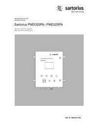
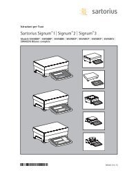
General View of the Equipment<br />
<strong>Combics</strong> 1 and 2<br />
1 Level indicator<br />
2 Load plate<br />
3 Leveling feet<br />
4 Indicator<br />
5 Display (for a detailed diagram, please see the chapter<br />
“Operating Design”)<br />
6 General Function Keys: Zero, Tare, Switch function, Adjustment/<br />
Calibration, Print/Data output<br />
(see “Operating Design”)<br />
7 On/Off Key<br />
<strong>Combics</strong> 2 only<br />
8 10 digit keypad for entering values<br />
9 LEDs<br />
(for checkweighing and classification)<br />
10 Additional function keys (see “Operating Design”)<br />
11 Toggle between weighing platforms (WP)<br />
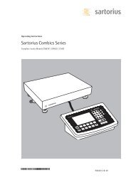
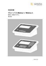
Rear view of indicator:<br />
Device Description<br />
8 Connection options for<br />
– COM 1 standard<br />
– 2nd UNICOM interface for additional, optional functions<br />
(e. g. Ethernet, profi bus, etc.)<br />
– <strong>CAW2S</strong>: a barcode scanner can be connected via a terminal<br />
block<br />
9 Power cord with country-specific plug<br />
10 Vent valve: 1.5 Nm<br />
11 Weighing platform WP 1 and/or WP 2 connection<br />
12 Input for menu access switch (standard or legal-for-trade mode)<br />
for WP 1 and/or WP 2<br />
13 RS-232C interface “COM 1” (standard equipment)<br />
14 Second “UNICOM” interface (<strong>Combics</strong> 2 only)<br />
15 <strong>Combics</strong> 2 only: PS/2 connection (barcode scanner, external<br />
keypad)<br />
Operating Instructions <strong>Combics</strong> Indicators 7
Installation<br />
3 Once<br />
3 If<br />
3 Suspension<br />
8 Operating Instructions <strong>Combics</strong> Indicators<br />
Installation<br />
When a <strong>Combics</strong> complete scale is ordered with special equipment, the desired<br />
options come pre-loaded from the factory.<br />
Storage and Shipping Conditions<br />
the equipment has been removed from the packaging, it may lose accuracy if<br />
subjected to strong vibration.<br />
the load plate is lifted using a vacuum lifting pad, gloves, safety shoes and safety<br />
gear must be worn. Risk of injury! This work may only be carried out by reliable<br />
and authorized personnel.<br />
points are provided for weighing platforms with an overall size of<br />
1 + 1 m or larger.<br />
Do not step under the load during weighing platform/load plate transport or when<br />
lifting. Corresponding accident prevention regulations must be followed. Do not<br />
damage the clamp boxes and load receptors during transport.<br />
– Do not expose the equipment to unnecessarily extreme temperatures, moisture,<br />
shocks, blows or vibration.<br />
– Permissible storage temperature: –10°C to +40°C<br />
Installation location<br />
Avoid adverse infl uences at the place of installation:<br />
– Extreme temperatures (operating temperature: –10°C to +40°C)<br />
– Aggressive chemical vapors<br />
– Extreme moisture (according to IP protection class)<br />
Unpacking<br />
For devices with a platform size of 60 + 80 cm or larger:<br />
t Protective gear must be worn (safety shoes and if required, gloves)<br />
t Always lift on the side walls when lifting or transporting the weighing platform.<br />
t After unpacking the device, check it for any visible damage as a result of rough<br />
handling during shipment.<br />
y If you detect any damage, proceed as directed in the chapter entitled “Care and<br />
Maintenance” under “Safety Inspection."<br />
t Save the original packaging for any future transport.<br />
Unplug all connected cables before packing the equipment.<br />
Check package contents<br />
– Indicator<br />
– Weighing platform<br />
– Operating instructions<br />
– Options (special accessories) as listed on the bill of delivery
3<br />
CAH1 models: Remove transport locks<br />
t Place the weighing platform at its installation location, remove the<br />
weighing pan.<br />
t Remove the transport lock: Remove screw 1<br />
t Loosen screw 2.<br />
t Turn the mounting bracket 180° and re-secure screw 2.<br />
t Re-attach screw 1 to the lever<br />
The transport lock must be re-installed before transporting the weighing platform.<br />
Weighing Platform, Leveling<br />
The weighing platform must be exactly level to ensure reproducible weighing results<br />
every time. Therefore, the weighing platform must always be re-leveled after it has<br />
been moved to a different location.<br />
t Remove the weighing pan.<br />
t Loosen the lock nuts using a wrench (SW17).<br />
t Use a SW5 Allen key to screw the leveling feet in/out.<br />
Installation<br />
Turning the leveling feet clockwise lifts the weighing platform,<br />
turning the leveling feet counterclockwise lowers the weighing platform.<br />
Operating Instructions <strong>Combics</strong> Indicators 9
Installation<br />
10 Operating Instructions <strong>Combics</strong> Indicators<br />
t Align the weighing platform leveling feet so that air bubble is centered within<br />
the circle of the level indicator.<br />
t Check to ensure that all four leveling feet rest securely on the work surface.<br />
y Each of the leveling feet must support an equal load.<br />
t Re-fasten the lock nuts after leveling:<br />
Small platforms (1 measuring cell) counter to the platform frame,<br />
large platforms (4 measuring cells) counter to the platform foot.<br />
t Place the weighing pan on the scale.<br />
Operating Limits<br />
You should not exceed the highest load for weighing platforms.<br />
The highest capacity for the weighing platform is as follows depending on the load<br />
used (center, side, one-sided corner load):<br />
Platform size Center Side Corner<br />
320 + 240 50 35 20<br />
400 + 300 130 85 45<br />
500 + 400 300 200 100<br />
500 + 400 P* 600 400 200<br />
650 + 500 S** 450 300 150<br />
800 + 600 P* 1200 800 400<br />
800 + 600 S** 900 600 300<br />
800 + 800 4500 3000 1500<br />
1000 + 800 4500 3000 1500<br />
1000 + 1000 4500 3000 1500<br />
1250 + 1000 4500 3000 1500<br />
1500 + 1250 4500 3000 1500<br />
1500 + 1500 4500 3000 1500<br />
2000 + 1500 4500 3000 1500<br />
* Steel<br />
** Stainless steel<br />
For CAH* models Platform size Supported load (center) in kg<br />
400 + 300 130<br />
560 + 450 130<br />
800 + 600 600
3 Superstructures<br />
Shock Resistance<br />
The weighing platform has a robust design; however, falling weighing samples, side<br />
impacts and shocks should be avoided. The weighing platform can withstand loads<br />
specifi ed in the DIN standard IEC68 Part 2-27.<br />
Notes on Planning Superstructures<br />
must be completely attached before the weighing platform is<br />
connected to the power.<br />
The weighing platform is designed for system integration. <strong>Scale</strong> drawings are the<br />
basis for the selection of the required superstructures. The fi xing of model CAH*IG*<br />
weighing platforms should be carried out using the YAS04IS fastening kit.<br />
Moving or rotating parts on the weighing pan must be designed so that the<br />
weighing results are not infl uenced. Rotating parts should be counterbalanced,<br />
for example.<br />
The weighing pan must be free on all sides so that there is no connection between<br />
the weighing platform and fi xed parts due to falling parts or dirt. Cables and hoses<br />
between the weighing platform and other devices may not exert any forces on the<br />
weighing platform. These cables may not touch the weighing pan.<br />
When setting up systems in hazardous areas (Zone 2 or 22), any relevant<br />
specifi cations should be observed, e. g.: EN60079-14.<br />
The design should ensure that moving parts do not cause electrostatic discharges<br />
(e. g. roller conveyors).<br />
Preload Range (Zero Set Range)<br />
The weight of the superstructures that are attached to the weighing platform is<br />
designated as a “preload.” The preload is electronically compensated for in the<br />
weighing platform so that the full weighing range remains available and thus<br />
zeroing and/or calibration/adjustment (with external weights) is possible.<br />
Greater preloads reduce the weighing capacity. You may not fall below the following<br />
weighing range values:<br />
– For CAH*E-16ED... and CAH*E-32ED... a min. 20 kg weighing range must be<br />
maintained<br />
– For CAH*E-64ED... and CAH*G-64FE... a min. 35 kg weighing range must be<br />
maintained<br />
– For CAH*G-150IG-H and CAH*G-300IG-H a min. 60 kg weighing range must be<br />
maintained<br />
The preload must always be set before verifi cation.<br />
Acclimatizing the Device<br />
Installation<br />
Condensation can form on the surfaces of a cold device when it is brought into a<br />
substantially warmer area.<br />
t Allow the device to acclimatize for about 2 hours at room temperature, leaving<br />
it unplugged from AC power.<br />
Operating Instructions <strong>Combics</strong> Indicators 11
Getting Started<br />
12 Operating Instructions <strong>Combics</strong> Indicators<br />
Getting Started<br />
Steps 1.) Set up the weighing platform with the indicator.<br />
2.) Level the weighing platform<br />
3.) Connect peripheral devices, e .g. printer to the COM 1 or UNICOM interface:<br />
see Data Interfaces chapter starting on page 99<br />
4.) Connect the device to AC power<br />
5.) Carry out an alignment: for adjustment, see page 27, for linearization see<br />
page 24<br />
3 The<br />
3 Peripheral<br />
3 Disconnect<br />
Connecting Peripheral Devices or Another Weighing Platform<br />
An analog Sartorius platform (CAPP, CAPS) or an IS weighing platform is connected<br />
at the factory to the <strong>Combics</strong> indicator WP1 input.<br />
load cell should be connected by a certified technician who has received specialized<br />
training from Sartorius. Any installation work that does not conform to the<br />
instructions in this manual results in forfeiture of all claims under the manufacturer’s<br />
warranty.<br />
devices should be connected by a certified technician who has received<br />
specialized training from Sartorius. Any installation work that does not conform to<br />
the instructions in this manual results in forfeiture of all claims under the manufacturer’s<br />
warranty.<br />
the equipment from the power supply before starting connection work.<br />
t Place cables from peripheral devices next to the indicator.<br />
<strong>CAW1S</strong>, <strong>CAW2S</strong> (IP69K) t Opening the <strong>Combics</strong> indicator:<br />
Loosen the ten cap nuts on the front panel. Remove the front panel.<br />
3 The<br />
Installing Connection and Interface Cables<br />
cable gland (IP69K protection) is pre-mounted on the indicator.<br />
Please use extreme caution when performing any work on the equipment that<br />
affects this cable gland.<br />
You must use a torque wrench. The torque for this cable gland is 5 Nm.<br />
Preparing Cables<br />
t Strip approx. 14 cm from the end of the cable.<br />
t Shorten the shielding to approx. 2 cm and pull back over the insulation.<br />
t Strip approximately 5 mm of the insulation from the wires of the connecting<br />
cable and affi x ferrules to the wire ends.
Com 1<br />
D<br />
2<br />
1 5<br />
3<br />
3 Please<br />
4<br />
Attaching the Cable Entry<br />
use extreme caution when performing any work on the equipment that<br />
affects this cable gland. You must use a torque wrench.<br />
The torque for this cable gland is 5 Nm.<br />
t Remove the protective cap from the bore hole on the indicator.<br />
t Insert the included cable gland through the bore hole and secure from the inside<br />
using the locknut (1).<br />
t Insert the cable through the cable gland until the shielding (2) comes into<br />
contact with the clamps (3). Tighten the screw-down nut (4) until the gasket (5)<br />
inserted between the screw-down nut and cable forms a small beaded rim.<br />
t Check the shielding and clamps.<br />
t Securely connect the wires of the connecting cable in accordance with the<br />
terminal assignments.<br />
t After you close the housing again, use a pressure gauge to check the integrity of<br />
the IP69K protection. For details, contact the Sartorius Service Center.<br />
Connecting Cables<br />
t Insert all cable wires through the ferrite case, wind them around the ferrite case<br />
and then reinsert back through the ferrite case.<br />
t Screw the wires tightly into the clamps.<br />
See the following pages for terminal pin allocation<br />
t Refer to the data sheet or operating instructions of the weighing platform for<br />
details on the assignment of wire colors/signals. Ensure any lines that are not<br />
assigned are insulated correctly.<br />
t When connecting a load receptor that uses 4-conductor technology (the cable of<br />
the weighing platform to be connected only has 4 lines), connect clamp pairs 1<br />
and 2 (EXC+ und SENSE+), and 5 and 6 (SENSE- und EXC-) with a wire jumper.<br />
Connecting Peripheral Devices: <strong>Combics</strong> 1,<br />
Model <strong>CAW1S</strong><br />
Digital PCB<br />
COM1 terminal assignments<br />
1 LOAD_PRINTER 11 Clear to Send (CTS)<br />
2 RESET_OUT 12 Data Terminal Ready (DTR)<br />
3: GND 13 Data Input (RXD)<br />
4 GND 14 Data Output (TXD)<br />
5 5V_OUT 15 GND<br />
6 5V geschaltet 16 Universal In<br />
7 GND 17 Control Output: “lighter"<br />
8 GND 18 Control Output: “equal"<br />
9 n.c. 19 Control Output: “heavier"<br />
10 LINE_OUT 20 Control Output: “set"<br />
D connection of indicator<br />
Getting Started<br />
Operating Instructions <strong>Combics</strong> Indicators 13
PS/2<br />
PS/2<br />
Getting Started<br />
Com 1<br />
Com 1<br />
LED<br />
D<br />
PS/2 Com 1 A6/7<br />
LED<br />
Com 1<br />
LED<br />
D<br />
D<br />
D<br />
Weighing platform<br />
Interface 1<br />
Weighing platform<br />
Interface 2<br />
Weighing platform<br />
Interface 2<br />
A20<br />
14 Operating Instructions <strong>Combics</strong> Indicators<br />
Plattform: -MCE, -UCE, -RCE: Connection for ADU 10.000e<br />
1 EXC+<br />
2 SENSE+<br />
3 OUT+<br />
4 OUT-<br />
5 SENSE-<br />
6 EXC<br />
D connection of indicator<br />
Interface Pin Assignments: <strong>Combics</strong> 2, Model <strong>CAW2S</strong><br />
Digital PCB<br />
COM1 terminal assignments (applies to all PCBs)<br />
1 LOAD_PRINTER 11 Clear to Send (CTS) 21 5 V switched<br />
2 RESET_OUT 12 Data Terminal Ready (DTR) 22 PS/2_Data<br />
3: GND 13 Data Input (RXD) 23 PS/2_Clock<br />
4 GND 14 Data Output (TXD) 24 GND<br />
5 5V_OUT 15 GND 31 Not assigned<br />
6 5V switched 16 Universal In 32 Not assigned<br />
7 GND 17 Control Output: “lighter" 33 Not assigned<br />
8 GND 18 Control Output: “equal" 34 Not assigned<br />
9 n.c. 19 Control Output: “heavier" 35 Not assigned<br />
10 LINE_OUT 20 Control Output: “set" 36 Not assigned<br />
D Indicator connection<br />
LED (LED connection)<br />
Interface PCB for RS-232/485 for IS weighing platform<br />
(option A6/A7)<br />
A6/7<br />
1 CTS 11 TxD/RxD+<br />
2 DTR 12 TxD/RxD-<br />
3 RxD 13 LINE_OUT<br />
4 TxD 14 LINE_OUT<br />
5 GND 15 GND<br />
6 Calibration Lock 16 GND<br />
D Indicator connection<br />
LED (LED connection)<br />
Interface PCB for ADC 10.000e (option A20)<br />
A20<br />
1 EXC+<br />
2 SENSE+<br />
3 OUT+<br />
4 OUT-<br />
5 SENSE-<br />
6 EXC-<br />
D Indicator connection<br />
LED (LED connection)
PS/2<br />
Com 1 A62/72<br />
LED<br />
D<br />
Weighing platform<br />
Interface 2<br />
Interface PCB for RS-232/485 for IS weighing platform<br />
(option A62/A72)<br />
Interface PCB A6/7 and A62/72<br />
1 CTS 11 TxD/RxD+<br />
2 DTR 12 TxD/RxD-<br />
3 RxD 13 LINE_OUT<br />
4 TxD 14 LINE_OUT<br />
5 GND 15 GND<br />
6 Calibration Lock 16 GND<br />
D Indicator connection<br />
LED (LED connection)<br />
Pin Assignment Chart<br />
Models <strong>CAW1P</strong> and <strong>CAW2P</strong> (IP44 protection)<br />
Getting Started<br />
COM1 female connectors:<br />
25-pin D-Submini female connector (DB25S) with screw lock hardware for cable<br />
gland<br />
Recommended interface connector:<br />
25-pin D-Submini (DB25) with shielded cable clamp assembly and shield plate<br />
(Amp type 826 985-1C) and fastening screws (Amp type 164868-1)<br />
COM1 pin assignments<br />
Pin 1: Shield<br />
Pin 2: Data output (TxD)<br />
Pin 3: Data input (RxD)<br />
Pin 4: GNO<br />
Pin 5: Clear to Send (CTS)<br />
Pin 6: Not assigned<br />
Pin 7: Internal ground (GND)<br />
Pin 8: Internal ground (GND)<br />
Pin 9: Not assigned<br />
Pin 10: Not assigned<br />
Pin 11: +12 V for printer<br />
Pin 12: RES_OUT\<br />
Pin 13: +5 V Switch<br />
Pin 14: Internal ground (GND)<br />
Pin 15: Universal switch<br />
Pin 16: Control output: “lighter"<br />
Pin 17: Control output: “equal"<br />
Pin 18: Control output: “heavier"<br />
Pin 19: Control output: “set”<br />
Pin 20: Data Terminal Ready (DTR)<br />
Pin 21: Ground power supply (GND)<br />
Pin 22: Not assigned<br />
Pin 23: Not assigned<br />
Pin 24: Power supply +15...25 V (peripherals)<br />
Pin 25: +5 V<br />
Operating Instructions <strong>Combics</strong> Indicators 15
Getting Started<br />
Getting Started<br />
PS/2 socket pin assignment on <strong>Combics</strong> 2<br />
Pin 1:<br />
PS/2<br />
Keyboard<br />
socket<br />
data<br />
pin<br />
(data<br />
assignment<br />
interface<br />
on<br />
cable)<br />
<strong>Combics</strong> 2<br />
6 5 Pin 2:<br />
Pin<br />
Not assigned<br />
1: Keyboard data (data interface cable)<br />
4 6 3 Pin 53:<br />
Pin<br />
GND<br />
2:<br />
(ground)<br />
Not assigned<br />
4<br />
3 Pin 3: GND (ground)<br />
2<br />
1 Pin 4: 5V switched<br />
2<br />
Pin 15:<br />
Pin<br />
Keyboard<br />
4:<br />
clock<br />
5V switched<br />
Pin 6:<br />
Pin<br />
Not assigned<br />
5: Keyboard clock<br />
Pin 6: Not assigned<br />
3<br />
16 Operating Instructions <strong>Combics</strong> Indicators<br />
Operating Instructions <strong>Combics</strong> <strong>Complete</strong> <strong>Scale</strong>s<br />
Connecting Connecting an IS Weighing an IS Weighing Platform Platform to a <strong>Combics</strong> to a <strong>Combics</strong> 2 2<br />
You can connect<br />
You can<br />
an<br />
connect<br />
IS weighing<br />
an IS<br />
platform<br />
weighing<br />
to<br />
platform<br />
WP2.<br />
to WP2.<br />
Features<br />
Features<br />
– IS weighing<br />
– IS<br />
platforms<br />
weighing<br />
process<br />
platforms<br />
weighing<br />
process<br />
data<br />
weighing<br />
independently<br />
data independently<br />
of the indicator.<br />
of the indicator.<br />
– Internal<br />
–<br />
calibration/adjustment<br />
Internal calibration/adjustment<br />
option<br />
option<br />
– IS...-0CE<br />
–<br />
models:<br />
IS...-0CE<br />
have<br />
models:<br />
a separate<br />
have a<br />
approval<br />
separate<br />
number,<br />
approval<br />
printed<br />
number,<br />
on<br />
printed<br />
a tag that<br />
on<br />
is<br />
a tag that is<br />
affixed to the<br />
affi xed<br />
cable.<br />
to the cable.<br />
– Please<br />
–<br />
observe<br />
Please<br />
the<br />
observe<br />
conditions<br />
the conditions<br />
described in<br />
described<br />
the manual<br />
in the<br />
for<br />
manual<br />
the weighing<br />
for the<br />
platform<br />
weighing platform<br />
you connect.<br />
you connect.<br />
Cabling Diagram - Connection to a PC<br />
Use the following cables to connect a PC to the indicator in accordance with the<br />
Cabling Diagram RS-232C/V24 - Connection standard (max. to cable a PClength<br />
15 m):<br />
Models <strong>CAW1P</strong>, <strong>CAW2P</strong>: connecting cable 7357312<br />
Use the following cables to connect a PC to the indicator in accordance with the<br />
Models <strong>CAW1S</strong>, <strong>CAW2S</strong>: connecting cable YCC02-D9F6<br />
RS-232C/V24 standard (max. cable length 15 m):<br />
Models <strong>CAW1P</strong>, <strong>CAW2P</strong>: connecting cable 7357312<br />
Models <strong>CAW1S</strong>, <strong>CAW2S</strong>: connecting cable YCC02-D9F6<br />
V24<br />
V24<br />
NOTE: This equipment has been tested and found to comply with the limits pursuant to part<br />
15 of FCC Rules. These limits are designed to provide reasonable protection against harmful<br />
interference. This equipment generates, uses and can radiate radio frequency energy and, if<br />
not installed and used in accordance with these instructions, may cause harmful interference<br />
to radio communications. For information on the specific limits and class of this equipment,<br />
please refer to the Declaration of Conformity. Depending on the particular class, you are either<br />
required or requested to correct the interference. If you have a Class A digital device, you need<br />
to comply with the FCC statement as follows: “Operation of this equipment in a residential<br />
area is likely to cause harmful interference in which case the user will be required to correct the<br />
interference at his own expense.“
Cable Diagrams<br />
Pin assignments for the cable from the indicator to an RS-232 PC interface (COM1).<br />
Indicator side PC side<br />
Models <strong>CAW1P</strong>, <strong>CAW2P</strong> DSUB connector<br />
25-pin D-Sub male connector<br />
1<br />
9-pin or 25-pin<br />
Sgn GND 7 5 GND 7 GND<br />
TxD 2 2 RxD 3 RxD<br />
RxD 3 3 TxD 2 TxD<br />
DTR 20 8 CTS 5 CTS<br />
CTS 5 4 DTR 20 DTR<br />
Models <strong>CAW1S</strong>, <strong>CAW2S</strong><br />
Open cable end DSUB connector<br />
9-pin or 25-pin<br />
Sgn GND 15 5 GND 7 GND<br />
TxD 14 2 RxD 3 RxD<br />
RxD 13 3 TxD 2 TxD<br />
DTR 12 8 CTS 5 CTS<br />
CTS 11 4 DTR 20 DTR<br />
3 The<br />
Closing the <strong>Combics</strong> Indicator<br />
t Re-attach the front panel and secure it with the ten cap nuts ( 1Nm ).<br />
Connecting the Device to AC Power<br />
The indicator is powered through the pre-installed power cord. The power supply is<br />
integrated into the indicator. The device can be operated with a supply voltage of<br />
100 V to 240 V.<br />
power connection must be made in accordance with the regulations applicable<br />
in your country.<br />
Make sure that the voltage rating printed on the manufacturer's ID label is identical<br />
to that of your local line voltage. If the voltage specifi ed on the label or the plug<br />
design of the AC adapter do not match the rating or standard you use, please<br />
contact your Sartorius offi ce or dealer.<br />
t Check the voltage rating and plug design.<br />
t The device must be plugged into a properly installed wall outlet.<br />
Getting Started<br />
Operating Instructions <strong>Combics</strong> Indicators 17
Getting Started<br />
3 If<br />
18 Operating Instructions <strong>Combics</strong> Indicators<br />
Protection Class 1 Device<br />
t The device must be plugged into a properly installed wall outlet which has<br />
a protective grounding conductor (PE).<br />
Safety Precautions<br />
you use an electrical outlet that does not have a protective grounding conductor,<br />
ensure that an equivalent protective conductor is installed by a certified electrician<br />
(as specified in the applicable regulations for installation in your country). The protective<br />
effect must not be negated by using an extension cord without a protective<br />
grounding conductor.<br />
Before using for the fi rst time, any superstructure parts must be completely installed.<br />
Avoid connecting the equipment to lines that have a heavy electrical load, e. g.<br />
compressors, large machinery, etc.<br />
Warm-up Time<br />
To deliver exact results, the device must warm up for at least 30 minutes after<br />
connection to AC power. Only after this time will the device have reached the<br />
required operating temperature.<br />
Using a Verified Device in Legal Metrology:<br />
Ensure that there is a warm-up time of at least 24 hours after connection to the<br />
power supply.<br />
Connecting a Barcode Scanner (Accessory; Order No. YBR03PS2)<br />
t Disconnect the indicator from AC power (unplug the AC adapter)<br />
For <strong>CAW2P</strong> models:<br />
t Connect the barcode scanner via PS/2.<br />
For <strong>CAW2S</strong> models:<br />
t Please see “Pin Assignment Charts,” page 15 (implemented via the YCC02-BR02<br />
connecting cable or as option M8)
<strong>Scale</strong> Confi guration<br />
Service Mode<br />
Confi guring Weighing Platforms<br />
Purpose The Service mode enables access to additional menu items in the Setup menu<br />
(setup) which are not displayed when the Service mode is not active. The most<br />
important calibration and adjustment work for the indicator and for the connected<br />
weighing platform can be carried out in the Service menu, e. g. ADC confi guration.<br />
When the Service mode is active, an “S” is shown in the top right-hand corner of the<br />
display. To deactivate the Service mode, restart the indicator (turn the indicator off<br />
and back on again).<br />
In Service mode, the Setup menu is expanded with the following parameters after<br />
entering the user password:<br />
– S-DATE for entering the next service date<br />
– SER.NO for entering the device serial number<br />
– MODEL with the model description<br />
– S-SQMIN<br />
– ALIB.MEM for deleting the Alibi memory<br />
The Setup menu for WP1 and WP2 can be extended to include the following<br />
setting options:<br />
Param1<br />
CAL./ADJ. Calibration, adjustment 1.9.<br />
Internal linearization (for WP-2 only) 1.9.5<br />
CAL.EXT External linearization with default weights 1.9.6<br />
CAL.E.USR. External linearization with user-defi ned weights (entered under 1.18) 1.9.7<br />
SET.PREL. Setting the preload 1.9.8<br />
DEL.PREL. Clearing the preload 1.9.9<br />
HND.XT / CAL./ADJ. Entering the adjustment and linearization weights 1.18.<br />
LIN. WT.1 Entering the lin. weight 1 1.18.2<br />
LIN. WT.2 Entering the lin. weight 2 1.18.3<br />
LIN. WT.3 Entering the lin. weight 3 1.18.4<br />
LIN. WT.4 Entering the lin. weight 4 1.18.5<br />
ADJ.W/O.W Adjustment without weights (entering the characteristic data<br />
of the load cell(s)) 1.19.<br />
NOM.LOAD Nominal load 1.19.1<br />
RESOLUT Resolution 1.19.2<br />
SENSIT.1 Sensitivity in mV/V for cell 1 (or average value for all load cells) 1.19.3<br />
SENSIT.2 Sensitivity in mV/V for cell 2 1.19.4<br />
SENSIT.3 Sensitivity in mV/V for cell 3 1.19.5<br />
SENSIT.4 Sensitivity in mV/V for cell 4 1.19.6<br />
SAVE Save values for 1. 19 1.19.7<br />
GEOG.DAT Adjustment location (geographical data; or alternatively the<br />
gravitational acceleration at the place of installation) 1.20.<br />
LATITUD Latitude in degrees 1 20.1<br />
ALTITUD Elevation in meters above sea level 1 20.2<br />
GRAVITY. Gravitational acceleration 1 20.3<br />
SAVE. Save values for 1. 20 1 20.4<br />
ADC Confi guration 11<br />
Applying the serial number of the IS weighing platform (verifi ed weighing<br />
platform at WP2) 12.1<br />
Apply the serial number 12.1.1<br />
Inactive (standard WP) 12.1.2<br />
Operating Instructions <strong>Combics</strong> Indicators 19
Confi guring Weighing Platforms<br />
20 Operating Instructions <strong>Combics</strong> Indicators<br />
Activating the Service Mode<br />
e ... ) t Switch to the Menu mode (see page 32).<br />
k k ... t Access the Setup menu.<br />
) t Select Setup<br />
If a password is requested at this point, enter the service password<br />
(see Appendix) and continue with “Saving the service password."<br />
k k ... t Access the U-Code menu item<br />
) t Select U-Code<br />
t Enter the service password (see Appendix).<br />
) t Apply the service password<br />
y The Service mode is active: an “S” appears in the top right-hand corner of the<br />
display.<br />
( ( t Return to Setup in the Service mode.
Entering Geographical Data for Use in Legal Metrology<br />
Purpose Entering geographical data allows the external adjustment of weighing equipment<br />
at a place (e. g. at the manufacturer or vendor's place of business) that is not the<br />
same as the place of installation. If the weighing equipment is adjusted at the place<br />
of installation, it is not necessary to enter geographical data.<br />
The sensitivity of weighing equipment changes depending on the place of<br />
installation as it is dependent on the on-site gravitational force – or, more precisely,<br />
on gravitational acceleration. Saving geographical data makes it possible to change<br />
the place of installation of the weighing equipment after external adjustment has<br />
been carried out.<br />
The adjustment of weighing equipment is valid at the place of installation and<br />
within a specifi c tolerance zone. At 3000 e this zone extends ±100 km from the set<br />
geographical latitude and ±200 m from the set elevation above sea level.<br />
Installation Location in Germany An exception to this is the setting for “Germany (Zone D):” If during external<br />
adjustment of weighing equipment within Germany the geographical data<br />
– Geographical latitude: 51.00 degrees<br />
– 513 m elevation above sea level<br />
are entered, the weighing equipment can be used throughout Germany.<br />
Gravitational acceleration for “Germany (Zone D)” is 9.810 m/s 2 . On delivery the<br />
geographical data for “Germany (Zone D)” are entered in the output device.<br />
It is recommended to use the geographical data settings for “Germany (Zone D)”<br />
when adjusting and delivering the weighing equipment within Germany. Entering<br />
exact geographical data will lead to a higher level of accuracy but will also restrict<br />
the tolerance zone.<br />
Setup Information – It is only possible to enter geographical data when the menu access switch is<br />
open.<br />
– When the Service mode is activated, you can enter geographical data in the<br />
Setup menu for the fi rst weighing platform under WP-1 and COM1 / WP-2,<br />
UNICOM / WP-2 or COM-WP for the second weighing platform. The settings are<br />
made in the corresponding Setup menu under menu item 1.20.<br />
– You can enter either the “geographical latitude in degrees” (LATITUD menu<br />
item 1.20.1) and “elevation in m above sea level” (ALTITUD menu item 1.20.2),<br />
or the value for gravitational acceleration (GRAVITYmenu item 1.20.3).<br />
Gravitational acceleration takes precedence over the geographical latitude and<br />
elevation of the location: If it has been entered, input fi elds for latitude and<br />
elevation show the values 99999.99 and 9999999 respectively. If only elevation<br />
and latitude have been entered, 0000000 is displayed for gravitational<br />
acceleration.<br />
3 If<br />
Confi guring Weighing Platforms<br />
you return to the highest level of the Setup menu without saving the<br />
configuration parameter beforehand (save menu item 1.20.4) any settings that<br />
have been made will be deleted.<br />
Operating Instructions <strong>Combics</strong> Indicators 21
Confi guring Weighing Platforms<br />
22 Operating Instructions <strong>Combics</strong> Indicators<br />
Procedure t Open the menu access switch.<br />
If the device is part of a verifi ed weighing facility, this will only be possible if the<br />
verifi cation seal is broken. The weighing equipment must then be verifi ed again.<br />
t Activate the Service mode.<br />
t Select the weighing platform.<br />
t Enter the geographical data for the place of adjustment under menu items<br />
1.20.1 to 1.20.3 and save them under menu item 1.20.4. The data can be<br />
obtained from the relevant land registry or Ordnance Survey.<br />
t Carry out external calibration.<br />
t After the calibration, enter the geographical data for the place of installation<br />
under menu items 1.20.1 to 1.20.3 and save them under menu item 1.20.4.<br />
t Close the menu access switch.<br />
y The weighing equipment can now be operated at the place of installation, and<br />
within the abovementioned tolerance zone.<br />
Note: The set geographical values are displayed during the adjustment procedure if the<br />
display of the data has been activated in the Setup menu under UTILIT. menu item<br />
8.12.2 (factory setting: 8.12.1, display deactivated).<br />
When the display is activated the adjustment procedure is as follows:<br />
y If the elevation and geographical latitude are used, the word ALTITUD will<br />
appear briefl y followed by the set elevation (in meters above sea level) after the<br />
start of the CAL adjustment procedure.<br />
t Confi rm the display using the ) key (cancel using the ( key).<br />
y Then the word LATITUD will be displayed briefl y followed by the set<br />
geographical latitude in degrees.<br />
t Confi rm the display using the ) key (cancel using the ( key).<br />
y You are then asked to place the calibration weight on the weighing platform.<br />
If gravitational acceleration has been entered instead of elevation and<br />
geographical latitude, the word GRAVITY will appear briefl y, followed by the set<br />
value for gravitational acceleration.<br />
t Confi rm the display using the ) key (cancel using the ( key).<br />
Menu structure for entering the geographical data<br />
GEOG.DAT Adjustment location (geographical data; or alternatively<br />
the gravitational acceleration at the place of installation) 1.20.<br />
LATITUD Latitude in degrees 1.20.1<br />
ALTITUD Elevation in meters above sea level 1.20.2<br />
GRAVITY. Gravitational acceleration 1.20.3<br />
SAVE. Save values for 1. 20 1.20.4
Entering Adjustment and Linearization Weights<br />
Purpose Entering adjustment and linearization weights.<br />
Setup Information – The Service mode must be activated in order for linearization weights to be<br />
entered under menu items 1.18.2 to 1.18.5 (see page 20).<br />
– Adjustment and linearization weights can be entered in the Setup menu under<br />
WP-1 for the fi rst weighing platform and COm1 / WP-2, UNICOM / WP-2 or<br />
COm-WP for the second weighing platform. The settings are made in the<br />
corresponding Setup menu under menu item 1.18.<br />
– The Service mode does not have to be activated in order for external userdefi<br />
ned adjustment weights to be entered under menu item 1.18.1.<br />
– The adjustment and linearization weights must be entered in the unit selected<br />
for the ADC confi guration under menu item 11.8.<br />
Procedure t Activate the Service mode (only necessary if linearization weights are going to<br />
be entered)<br />
t Select the weighing platform.<br />
t Enter the external user-defi ned adjustment weight under menu item 1.18.1<br />
t Enter the external linearization weight under menu items 1.18.2 to 1.18.5.<br />
Menu structure for entering the adjustment and linearization weights<br />
HND.XTEntering the adjustment and linearization weights 1.18.<br />
Entering external user-defi ned adjustment weight (Service mode not required) 1.18.1<br />
LIN. WT.1 Entering the lin. weight 1 1.18.2<br />
LIN. WT.2 Entering the lin. weight 2 1.18.3<br />
LIN. WT.3 Entering the lin. weight 3 1.18.4<br />
LIN. WT.4 Entering the lin. weight 4 1.18.5<br />
Function Allocation of the J Key<br />
Purpose The J key is usually used for the calibration/adjustment function. For detailed<br />
information about calibration and adjustment, see “Operation” starting on page 45.<br />
The following additional functions can be allocated to the key when the Service<br />
mode is activated:<br />
– External linearization with default weights (menu item 1.9.6)<br />
– External linearization with the linearization weights (menu item 1.9.7) entered<br />
under menu item 1.18<br />
– Internal linearization (for WP-2 only) (menu item 1.9.5)<br />
– Set preload function (menu item 1.9.8)<br />
– Clear preload function (menu item 1.9.9)<br />
3 Once<br />
linearization has been completed, or after a preload has been set or deleted<br />
the function of the J key must be reallocated back to its original function in the<br />
Setup menu, e.g. external calibration/adjustment with default weights (see menu<br />
item 1.9).<br />
Menu structure for the function allocation of the J key<br />
Confi guring Weighing Platforms<br />
CAL./ADJ. Calibration, adjustment 1.9.<br />
Ext. calibration/adjustment with default weights (Service mode not required) 1.9.1<br />
Ext. calibration/adjustment with user-defi ned weights<br />
(Entry under 1.18, Service mode not required) 1.9.3<br />
CAL.INT Internal linearization (for WP-2 only) 1.9.5<br />
CAL.EXT External linearization with default weights 1.9.6<br />
CAL.E.USR. External linearization with user-defi ned weights (entered under 1.18) 1.9.7<br />
SET.PREL. Setting the preload 1.9.8<br />
DEL.PREL. Clearing the preload 1.9.9<br />
BLOCKED Key blocked 1.9.10<br />
Operating Instructions <strong>Combics</strong> Indicators 23
Confi guring Weighing Platforms<br />
24 Operating Instructions <strong>Combics</strong> Indicators<br />
External Linearization<br />
Setup Information – External linearization when weighing in legal metrology is only possible when<br />
the menu access switch is open.<br />
– The “external linearization” function must be allocated to the J key (menu<br />
item 1.9.6 or 1.9.7).<br />
3 Once<br />
linearization has been completed, the J key must be reallocated back to its<br />
original function in the Setup menu, e. g. external calibration/adjustment with<br />
default weights (Setup menu item 1.9).<br />
Procedure<br />
t For scales used in legal metrology: Open the menu access switch.<br />
( t Zero the weighing platform.<br />
t Activate the Service mode (see Page20).<br />
J t Start linearization.<br />
t After approximately 2 seconds you will be prompted to place the fi rst<br />
linearization weight on the platform.<br />
t Place the required weight on the platform.<br />
y After a short time the difference between the measured value and the true<br />
weight of the sample will be displayed.<br />
) t Save the linearization weight (cancel using the ( key).<br />
y You will then be prompted to place the second linearization weight on the<br />
platform.<br />
t Repeat the procedure for all required linearization weights.<br />
y After the last linearization weight has been saved you will be prompted to<br />
remove any load from the weighing pan.<br />
t Unload the weighing pan.<br />
t After a short period of time the zero point will be applied automatically and the<br />
indicator will automatically switch back to weighing mode.<br />
t Re-close the menu access switch.
Setting the Preload<br />
Setup Information – Setting the preload when weighing in legal metrology is only possible when the<br />
menu access switch is open.<br />
– The “Set Preload” function (menu item 1.9.8) must be allocated to the J key<br />
(see page 137).<br />
3 Once<br />
the preload has been set, the J key must be reallocated back to its original<br />
function in the Setup menu, e. g. external calibration/adjustment with default<br />
weights (Setup menu item 1.9).<br />
Procedure<br />
t For scales used in legal metrology: Open the menu access switch.<br />
( t Zero the weighing platform.<br />
t Place the preload weight on the weighing platform.<br />
J t Start the “Set Preload” function.<br />
y After a short period of time the preload will be applied and the indicator will<br />
automatically switch back to weighing mode.<br />
t Re-close the menu access switch.<br />
Confi guring Weighing Platforms<br />
Operating Instructions <strong>Combics</strong> Indicators 25
Confi guring Weighing Platforms<br />
26 Operating Instructions <strong>Combics</strong> Indicators<br />
Clearing the Preload<br />
Setup Information – Deleting the preload when weighing in legal metrology is only possible when the<br />
menu access switch is open.<br />
– The “Delete Preload” function (menu item 1.9.9) must be allocated to the J<br />
key (see page 137).<br />
3 Once<br />
the preload has been deleted, the J key must be reallocated back to its<br />
original function in the Setup menu, e. g. external calibration/adjustment with<br />
default weights (Setup menu item 1.9).<br />
Procedure<br />
t For scales used in legal metrology: Open the menu access switch.<br />
t Remove the preload weight from the weighing platform.<br />
) hold t Start the “Delete Preload” function.<br />
y After a short period of time the preload will be deleted and the indicator will<br />
automatically switch back to weighing mode.<br />
t Re-close the menu access switch.
3 Adjustment<br />
Adjustment without Weights<br />
In the Service menu, adjustment without weights can be carried out by entering the<br />
characteristic data of the load cells.<br />
without weights may not be carried out on weighing equipment used<br />
in legal metrology.<br />
Setup Information – Adjustment without weights is only possible when the menu access switch is<br />
open in the Service menu.<br />
– When the Service mode is activated, you can enter the necessary parameters for<br />
adjustment without weights in the Setup menu under WP-1 for the fi rst<br />
weighing platform and COm1 / WP-2, UNICOM / WP-2 or COm-WP for the second<br />
weighing platform. The settings are made in the corresponding Setup menu<br />
under menu item 1.19.<br />
– The “Nominal load” parameter must be entered in the kg unit.<br />
– The “Resolution” parameter must be entered in the kg unit and must correspond<br />
to the scale interval d entered for the ADC confi guration.<br />
– The “Sensitivity” parameter is entered in mV/V ( see the data sheet for the<br />
h<br />
value).<br />
Confi guring Weighing Platforms<br />
The data entered are saved by selecting menu item 1.19.7. After saving, the data will<br />
no longer be able to be read.<br />
Procedure<br />
t Open menu access switch.<br />
t Activate the Service mode.<br />
t Select the weighing platform.<br />
t Enter the nominal load of the load cell(s) in kg under menu item 1.19.1. If the<br />
weighing platform has multiple load cells, the nominal load must be multiplied<br />
accordingly (e. g. 4 load cells, each of which has a capacity of 50 kg, will<br />
produce a nominal load of 200 kg).<br />
t Enter the resolution in kg under menu item 1.19.2. The value must correspond<br />
to the scale interval d entered under menu item 11.4.1.<br />
t Enter the sensitivity of the load cells in mV/V under menu item 1.19.3.<br />
For weighing platforms with multiple load cells: Enter the individual values of<br />
the load cells in 1.19.3 to 1.19.6 or enter the average of all load cells in 1.19.3.<br />
t Save the values for adjustment without weighing under menu item 1.19.7.<br />
t Close the menu access switch.<br />
Menu structure for adjustment without weights<br />
ADJ.W/O.W Adjustment without weights (entering the characteristic data<br />
of the load cell(s)) 1.19.<br />
NOM.LOAD Nominal load 1.19.1<br />
RESOLUT Resolution 1.19.2<br />
SENSIT.1 Sensitivity in mV/V for cell 1 (or average value for all load cells) 1.19.3<br />
SENSIT.2 Sensitivity in mV/V for cell 2 1.19.4<br />
SENSIT.3 Sensitivity in mV/V for cell 3 1.19.5<br />
SENSIT.4 Sensitivity in mV/V for cell 4 1.19.6<br />
SAVE Save values for 1. 19 1.19.7<br />
Operating Instructions <strong>Combics</strong> Indicators 27
Operating Design<br />
28 Operating Instructions <strong>Combics</strong> Indicators<br />
Operating Design<br />
You can use the <strong>Combics</strong> 2 to record weight values from two weighing platforms,<br />
calculate and display weight values through application programs, and assign IDs to<br />
the samples weighed.<br />
First, use the menu to confi gure the indicator for the desired application (printer<br />
settings, etc.). Then you can begin weighing.<br />
The indicator keypad is used for operation. Each key can be assigned a weighing<br />
mode function and another function in the menu. Some of the keys also have an<br />
additional function when pressed and held for longer than 2 seconds.<br />
When a key is pressed that does not have an active operating mode function, an<br />
acoustical signal (double beep) sounds and the message “——-—” is displayed for<br />
2 seconds. The display then returns to the previous screen content.<br />
Switching on the Device<br />
e t Briefl y press the e key to turn on the indicator.<br />
y The device carries out a self test every time it is turned on. During this time,<br />
all display segments light up for several seconds.<br />
y Then the display for the weighing mode appears.<br />
The scale is started in the status it was in when it was turned off, e.g. with the<br />
last selected application.<br />
The scale starts in the weighing mode. You must open the Menu mode (see page 32)<br />
to make settings or set up applications.
Weighing Operation<br />
<strong>Combics</strong> 1 <strong>Combics</strong> 2<br />
Keys for all models<br />
e On/Off key<br />
When in Standby mode, STANDBY is displayed.<br />
( Zero key<br />
– Press the key less than 2 seconds: Zero<br />
– Press the key longer than 2 seconds: Displays the adjustment/confi guration<br />
counter<br />
) Tare key<br />
– Saves the numeric input as the tare weight<br />
– Press the key longer than 2 seconds: Start calibration/adjustment<br />
k Function key: Depends on the confi guration in the Setup menu, switches between the<br />
– First and second weighing unit<br />
– Gross and net values (<strong>Combics</strong> 1 only)<br />
– Normal and 10-fold higher display resolution (<strong>Combics</strong> 1 only)<br />
– Results display and SQmin display<br />
J ISO test: Start calibration or adjustment<br />
p Print key<br />
– Press the key less than 2 seconds: Print<br />
– Press the key longer than 2 seconds: Print GMP footer<br />
Keys for <strong>Combics</strong> 2 only<br />
n Toggle key: When two platforms are connected, this key toggles the display<br />
between the two readouts.<br />
The following four keys are used for operating the individual applications. Their<br />
exact function is described in the respective section for the application.<br />
c Delete key: Deletes initialization values or totalizing memory. During numeric entry<br />
the last character entered is deleted.<br />
r Reference value key: Changes the set reference value.<br />
O OK key: Applies values or starts an application program.<br />
Operating Design<br />
w Toggle key: Toggles between display modes within an application program.<br />
Operating Instructions <strong>Combics</strong> Indicators 29
Operating Design<br />
30 Operating Instructions <strong>Combics</strong> Indicators<br />
I Info key: Used to display application parameters and manual tare values (Info after<br />
pressing a follow-up key, e. g. ))<br />
1, 2, 3 ... ., 0 Number keys: Used to enter numeric values<br />
t To apply the value, press the corresponding function key (e.g. key ) to save<br />
the entry as a manual tare value.<br />
t To delete the last character entered, press the c key.<br />
D Application toggle key: Toggles between available applications<br />
d ID key: Used to enter operator IDs<br />
R Save key: Used to save values to the product data memory or load to the application<br />
K Resolution toggle key: Toggles to 10-fold increased resolution<br />
L Gross/Net value key: Toggles between the gross or net value<br />
Saving Settings in Weighing Mode<br />
All application parameters saved (e.g., reference values) remain in memory and are<br />
available when<br />
– the device has been switched off and then on again<br />
– you return to the originally selected application from a second one (e.g., when<br />
you switch from Averaging back to Counting all parameters saved for Counting<br />
are available).<br />
Applying the Tare Weight<br />
t Place the tare object on the weighing platform.<br />
t Press the ) key.<br />
y The value is applied as the tare value.<br />
Input Through the Digital Control Port<br />
You can connect an external hard drive or foot switch to the control port (universal<br />
interface). You can assign the following functions to the control port in the SETUP /<br />
CTRL IO / INPUT / PARAMET / EXT.KEYB menu:<br />
– p key<br />
– p key (hold)<br />
– ) key<br />
– J key<br />
– k key<br />
– n key<br />
– O key<br />
– ( key<br />
– e key<br />
– c key<br />
– I key<br />
– D key<br />
– K key<br />
– L key
The Display<br />
There are two display modes:<br />
– Display for weighing (weighing values and calculated values)<br />
– Display in “Menu mode” (device settings)<br />
The fi gure shows the display of the <strong>Combics</strong> 2<br />
Display in Weighing Mode 1 2 3 4 5<br />
20<br />
19<br />
18<br />
Appl. 1 Appl. 2 Appl. 3<br />
17<br />
16<br />
15 14<br />
1* Bar graph showing 10% intervals<br />
– Shows the percentage of the weighing platform’s capacity that is “used<br />
up” by the load on the scale (0% = lower limit, 100% = upper limit)<br />
or<br />
– Shows the measured value in relation to a target value (with the<br />
“Checkweighing” or “Classifi cation” applications)<br />
Minimum for checkweighing<br />
Maximum for checkweighing<br />
Target value for checkweighing<br />
2 S Symbol for active print job<br />
3 R8 Displays the active range on multiple-range scales<br />
4 Indicates active weighing platform; fl ashes to prompt calibration/adjustment<br />
5* 1 2 Selected weighing platform 1 or 2<br />
6 NET B/G Net/Gross value on the main display (with tare in memory or preset tare)<br />
7 k Identifi es the value on the main display as calculated (value not valid in<br />
legal metrology)<br />
8 Battery charge status<br />
9 p GMP-compliant printing in progress<br />
10 Weight unit of the value displayed<br />
11* Numeric display; e.g., showing the reference value<br />
12* Symbol indicating data transfer<br />
– Interface initialized (profi bus/Ethernet)<br />
– Flashes during data transfer (RS-232/485)<br />
13* Mem Symbol for product data memory<br />
14 In legal metrology, on equipment with e not equal to d, the digit<br />
bordered for identifi cation is not taken into account<br />
15* AUTO/OPT<br />
– AUTO: Depending on the weight value, a reaction is triggered in the application<br />
– OPT: Automatic optimization takes place for the Counting application<br />
16 Measured value line: Weight value or calculated value<br />
* = for <strong>Combics</strong> 2 only<br />
13<br />
Operating Design<br />
6<br />
7<br />
8<br />
9<br />
10<br />
Operating Instructions <strong>Combics</strong> Indicators 31<br />
12<br />
11
Operating Design<br />
32 Operating Instructions <strong>Combics</strong> Indicators<br />
1 2 3 4 5<br />
17* 18<br />
10<br />
Symbols for applications: An active application is identifi ed by a line above and<br />
below the symbol .<br />
Appl. 1 Appl. 2<br />
17<br />
Appl. 3<br />
Application 1*: A “Counting”/ “Neutral Measurement"<br />
B “Weighing in percent"<br />
V “Averaging” (animal weighing)<br />
Application 2*: H “Checkweighing"<br />
W “Classifi cation"<br />
Y “Checkweighing toward zero"<br />
Manually batching to a target value<br />
Application 3*: L “Totalizing"<br />
M “Net total formulation"<br />
20<br />
19<br />
18 a The zero-setting symbol is displayed after the active scale or weighing<br />
platform has been zeroed (verifi ed models only)<br />
19 + - Plus or minus sign of the value displayed<br />
20 l Busy symbol indicates that an internal process is in progress<br />
* = for <strong>Combics</strong> 2 only<br />
Menu Operating Design<br />
16<br />
15 14<br />
Switching to the Menu<br />
e t Turn on the device.<br />
If it is already on: turn off and then on again.<br />
) t During the display test, briefl y press the ) key.<br />
y The menu will open. The top most level is always displayed ( “APPLic.”), menu<br />
structure see page 131.<br />
Navigating the Menu<br />
You can navigate the menu using the keys with the white arrows under them.<br />
( Back to the superordinate menu level<br />
k Access the next menu item on the same level.<br />
This continues to page through on the same level.<br />
) Press less than 2 seconds: Select the menu item and save<br />
Press longer than 2 seconds: Exit the menu and switch to weighing mode<br />
p Print the menu settings starting from the current position,<br />
or print Info data<br />
13<br />
12<br />
11<br />
6<br />
7<br />
8<br />
9
1<br />
4 5 6 7<br />
2<br />
3<br />
2<br />
3<br />
Entering Numbers and Letters (without a number block)<br />
( – Press the key less than 2 seconds: Activate character to the left of the<br />
currently active character (when fi rst character is active: exit the input<br />
mode without saving changes)<br />
– Press the key longer than 2 seconds: Exit the input mode without saving<br />
changes<br />
) – Press the key less than 2 seconds:<br />
Confi rm currently active character and move 1 position to the right<br />
(after the last character: Save input)<br />
– Press the key longer than 2 seconds: Save current input and display the<br />
menu item<br />
k – Cursor in fi rst position, no characters changed yet: Delete character(s) and<br />
enter 0<br />
– Change the displayed character; scroll forward (sequence: 0 through 9,<br />
decimal point, minus sign, Z through A, space)<br />
p – Cursor in fi rst position, no characters changed yet: Delete entire string and<br />
enter a space<br />
– Change the displayed character; scroll backwards (sequence: Space,<br />
A through Z, minus sign, decimal point, 9 through 0 )<br />
Number entry for <strong>Combics</strong> 2:<br />
Enter number values (date and time, etc.) using the 10-key numeric keypad<br />
Menu Display<br />
Both illustrations depict all of the main display elements and symbols that can be<br />
shown in Menu mode.<br />
1 Selected menu item (e.g. printer for setting the connected printer)<br />
2 Menu history (refers to the highest menu level in the Setup menu)<br />
3 Note that other submenus are available<br />
Display with the “codes” language setting<br />
4 First level in the Setup menu<br />
5 Second level in the Setup menu<br />
6 Third level in the Setup menu<br />
7 Current active setting<br />
Saving Menu Settings<br />
Operating Design<br />
The parameters selected in the menu remain saved when you switch to weighing<br />
mode or turn off the device. You can block access to the Setup menu by requiring<br />
a password to prevent unauthorized or accidental setting changes (see page 35).<br />
Operating Instructions <strong>Combics</strong> Indicators 33
Operating Design<br />
34 Operating Instructions <strong>Combics</strong> Indicators<br />
Configuration<br />
Basic settings are made in the Menu mode by selecting the desired parameters.<br />
These are divided into the following groups (menu level 1), menu structure see<br />
page 126:<br />
– Application parameters APPLIC.<br />
– Function key FN-KEY<br />
– Device parameters SETUP<br />
– Device-specifi c information Info<br />
– User language LANGUAG.<br />
When used in legal metrology, not all parameters can be accessed. Only those<br />
parameters that can be selected are displayed. Factory-set parameters are identifi ed<br />
by an “*” in the list starting on page 127.<br />
Printing Parameter Settings<br />
t Access the Menu mode (see page 32)<br />
t Press the p key<br />
The scope of the printout depends on the position in the setup. It may take several<br />
seconds.<br />
Language, setting<br />
Example: Select the language “German.” The factory setting for language is “English."<br />
Menu: applic. / LANGuag .<br />
e t Turn on the device.<br />
t While all segments are lit, briefl y press the ) key.<br />
y The fi rst item in the main menu is shown: APPLic.<br />
k k ... t Press the k key until the LANGuag menu item appears for the language<br />
setting.<br />
) t Press the ) key to access the language setting sub-menu.<br />
y The currently set language is displayed.<br />
k k ... t Press the k key until u.s. mode is displayed.<br />
) t Press the ) key to save the selection.
y The small circle indicates that the setting has been saved.<br />
( Use the ( key to exit the menu level to make additional settings if required<br />
or<br />
) Press the ) key longer than 2 seconds to exit the menu.<br />
Setting up Password Protection<br />
e t Turn on the device.<br />
t While all segments are lit, briefl y press the ) key.<br />
y The fi rst item in the main menu is shown: APPLIC..<br />
k k ... t Press the k key until the SETUP menu item is displayed.<br />
) t Press the ) key to open the Setup sub-menu.<br />
y The fi rst parameter in the Setup sub-menu is displayed: WP-1.<br />
k k ... t Press the k key until U-CODE is displayed.<br />
) t Press the ) key to open the menu item.<br />
y The position for the fi rst character to be entered fl ashes.<br />
Operating Design<br />
p k t Use the p and k keys to select the desired character.<br />
The p starts the character selection with A alphabetical and the<br />
k key starts the character selection with 0 and counts upward.<br />
Operating Instructions <strong>Combics</strong> Indicators 35
Operating Design<br />
36 Operating Instructions <strong>Combics</strong> Indicators<br />
) t To apply a character, press the ) key.<br />
t Enter all additional characters of the password as described above.<br />
t Press and hold the ) key to save the password.<br />
( Use the ( key to exit the menu level to make additional settings if required<br />
or<br />
) Press the ) key longer than 2 seconds to exit the menu.<br />
Changing or Deleting Passwords<br />
t Open the U-CODE menu item in the SETUP menu as described above.<br />
y The old password must be entered to change or delete a password.<br />
t To change a password, overwrite the old password.<br />
t To delete a password, enter spaces and press the ) key.
Operation<br />
Weighing<br />
This application is always available during operation.<br />
Operation<br />
Features: – Zeroing by pressing (<br />
– Storing the weight on the platform as a tare by pressing )<br />
– Tare container weight automatically<br />
– Use a barcode scanner to enter tare weight (<strong>Combics</strong> 2)<br />
– Use a 10-key keypad to enter tare weight (<strong>Combics</strong> 2)<br />
– Delete tare values using the numeric entry 0 and ) / c and )<br />
(<strong>Combics</strong> 2)<br />
– Toggle the display using k between:<br />
– <strong>Combics</strong> 1: Gross and net values<br />
– 1st and 2nd weight unit or<br />
– <strong>Combics</strong> 1: Normal and 10-fold higher resolution<br />
– Weighing with two weighing platforms (for <strong>Combics</strong> 2 only)<br />
– Individual numeric ID codes for weight values (<strong>Combics</strong> 2)<br />
– Print weight value:<br />
– GMP-compliant printout<br />
– Automatic printout<br />
– Automatic data output (see Data Interfaces chapter)<br />
Automatic taring (APPLIC. menu item 3.7):<br />
When the menu item is active (3.7.2), the fi rst weight on the scale that exceeds the<br />
preset minimum load is stored in the tare memory at stability.<br />
The scale returns to the initial state when the load on the scale is less than 50% of<br />
the minimum load.<br />
Minimum load for automatic taring and automatic printing<br />
(menu item 3.5):<br />
You can set the following for the minimum load:<br />
1 digit (no minimum load)<br />
2 digits<br />
5 digits<br />
10 digits<br />
20 digits<br />
50 digits<br />
100 digits<br />
200 digits<br />
500 digits<br />
1000 digits<br />
The “digits” here refer to the scale intervals for the connected weighing platform.<br />
If the interval is 1 g and 1000 digits are required, the minimum load is 1000 g<br />
(1000 intervals).<br />
If the weighing platform interval is 5 g and the same number of digits as above are<br />
required, the minimum load is 5000 g.<br />
When the load exceeds the minimum load limit, the weighing platform is tared<br />
automatically and/or a report printout is generated automatically; however, this<br />
requires the corresponding menu items are active for automatic taring (menu item<br />
3.7.2) and for automatic printing (menu 7.15.2).<br />
Operating Instructions <strong>Combics</strong> Indicators 37
Operation<br />
38 Operating Instructions <strong>Combics</strong> Indicators<br />
Automatic printing (PROTOC menu item 7.15):<br />
When the menu item (7.15.2) is active, the fi rst weight value that exceeds the<br />
minimum load is printed.<br />
If the menu item is also activated for automatic taring, it is only tared when the<br />
minimum load is exceeded. In this case, an automatic printout would only be<br />
generated when the second weight value exceeds the minimum load.<br />
Main scale: first platform displayed on start-up (<strong>Combics</strong> 2 only)<br />
You can select the weighing platform to be displayed fi rst when <strong>Combics</strong> is turned<br />
on in the Setup menu under “UTILIT.” (menu item 8.11.).<br />
Entering a tare weight using a barcode scanner (<strong>Combics</strong> 2 only)<br />
The tare weight of the container can be entered via a barcode scanner. To do this,<br />
the Tare setting must be activated in the menu under Setup/Barcode.<br />
The value is applied and saved automatically, the t key does not have to be<br />
pressed. The content of the tare memory can be displayed in Info mode (I key).<br />
Entering the wRef application parameter using a barcode scanner<br />
(<strong>Combics</strong> 2 only)<br />
wRef application parameters can be entered via a barcode scanner. To do this, the<br />
wref setting must be activated in the menu under Setup/Barcode. The value is<br />
applied and saved automatically, the r key does not have to be pressed.<br />
Entering Identifier using a barcode scanner (<strong>Combics</strong> 2 only)<br />
Identifi ers can be entered via a barcode scanner.<br />
ID1: To do this, the ID1 setting must be activated in the menu under<br />
Setup/Barcode. The value is applied and saved automatically, the<br />
d key does not have to be pressed.<br />
ID2 to ID6: To do this, the HEADER setting must be activated in the menu under<br />
Setup/Barcode. Then press the d key until the desired ID entry<br />
appears, scan the barcode and save.<br />
Displaying the content of the identifiers:<br />
– d key<br />
Scanning barcodes directly<br />
You can directly scan a barcode using the barcode scanner.<br />
Menu setting: Setup / BARCODE/ INPUT<br />
The barcode can contain the following codes:<br />
- I for write identifi er<br />
- T for save tare memory<br />
- R for write reference weight<br />
- A for activate product data memory<br />
Examples: “I4Anton" = write the character string to ID 4: Anton<br />
“TC1" = write 1 Kg to the preset tare memory.<br />
“C” = unit: Kilograms<br />
“B” = grams<br />
“D” = carat,<br />
etc.<br />
“RC0.0023" = write 0.0023 kg as the reference weight<br />
“A1" = load product data memory 1<br />
Menu setting: Setup /BARCODE / HEADER<br />
The characters read from the barcode are shown in the weight value display.
Adjustment/Configuration Counter for Standard <strong>Scale</strong>s<br />
Operation<br />
Purpose Automatic recording of changes to adjustment and weighing parameters using two<br />
independent counters. The values remain saved for the life of the component.<br />
t To display both counters, press and hold the ( key for longer than 2 seconds.<br />
y The “Confi guration counter” is then shown in the weight display for 3 seconds<br />
(identifi ed by a P). Then the “Adjustment counter” is displayed for another<br />
3 seconds (identifi ed by a C). After 6 seconds, the information display turns off<br />
automatically.<br />
Adjustment Counter Features: – Counter limited to 9999<br />
– Counter at “C 0000” for hardware commissioning<br />
– Counter cannot be reset<br />
– Counter is updated automatically when:<br />
– linearization, calibration/adjustment is successful<br />
– user calibration, adjustment or linearization weight is changed (menu 1.18.)<br />
– When the following parameters are changed:<br />
Function of the q key (menu item 1.9.)<br />
Zero setting range (menu item 1.11)<br />
Tare/zero at power on (menu item 1.12)<br />
The above parameters are reset to factory settings (menu item 9.1.1)<br />
Configuration Counter Features: – Counter limited to 9999<br />
– Counter at “P 0000” for hardware commissioning<br />
– Counter cannot be reset<br />
– Counter is updated automatically when:<br />
– When the following parameters are changed:<br />
Installation location (menu item 1.1.)<br />
Application fi lter (menu item 1.2.)<br />
Stability range (menu item 1.3.)<br />
Taring (menu item 1.5)<br />
Auto zero (menu item 1.6.)<br />
Weight unit 1 (menu item 1.7.)<br />
Weight unit 2 (menu item 3.1.)<br />
Weight unit 3 (menu item 3.3.)<br />
The above parameters are reset to factory settings (menu item 9.1.1)<br />
– Switching the k key to or from a 10-fold higher resolution<br />
– Turning the application automatic taring on/off<br />
(menu item 3.7.)<br />
– The application parameters are reset to factory settings<br />
(menu item 9.1.1)<br />
Operating Instructions <strong>Combics</strong> Indicators 39
Operation<br />
40 Operating Instructions <strong>Combics</strong> Indicators<br />
Device Parameters<br />
Password protection<br />
Access to the device parameters Setup and application parameters APPLIC.<br />
(<strong>Combics</strong> 2) can be password-protected against unauthorized changes in the Setup<br />
menu under U-CODE (see page 35).<br />
Acoustic signal<br />
An acoustic signal (single beep for active, double beep for inactive keys) is emitted<br />
when you press a key.<br />
In the SETUP menu, the acoustic signal can be turned on/off under UTILIT. /<br />
PARAMET(ER) / SIGNAL (menu item 8.2.).<br />
Keypad<br />
The keypad can be blocked/released for entry in the SETUP menu under UTILIT. /<br />
PARAMET(ER) / KEYS (menu item 8.3.).<br />
Automatic shutoff of <strong>Combics</strong><br />
In the SETUP menu, the indicator can be shut off automatically using a timer under<br />
UTILIT. / PARAMET(ER) / AUTO.OFF (menu item 8.7.).<br />
Display lighting<br />
The following settings can be made for display lighting in the SETUP menu under<br />
UTILIT. / PARAMET(ER) / BACKLIT:<br />
– on (8.8.1)<br />
– off (8.8.2)<br />
– off automatically using a timer (8.8.3)<br />
Timer<br />
The timer for turning off the device and/or display lighting can be set to 2, 4, or<br />
10 minutes in the SETUP menu under UTILIT. / PARAMET(ER) / TIMER (menu<br />
item 8.9.)<br />
Example: Switch on the device, zero the scale, tare the container weight, place sample in the<br />
container, toggle display to gross weight or to second weight unit or 10-fold<br />
resolution<br />
e t Turn on the device.<br />
t All display segments appear (display test).<br />
y The display for no load on the scale appears.<br />
( t Press the ( key to zero the scale.<br />
y The display for a zeroed scale appears.
t Place the container on the weighing platform.<br />
y The container weight is displayed.<br />
) t Press the ) key to tare the scale.<br />
y The display for a tared scale with a container appears.<br />
t Place a sample in the container (in this example 120.2 g)<br />
y The display for a tared scale with weighing results appears.<br />
k t Press the k key to toggle the display.<br />
y The following is displayed depending on the confi guration:<br />
y The gross weight (in this example, 170.2 g = 50 g for container + 120.2 g for<br />
sample) (<strong>Combics</strong> 1)<br />
or<br />
y Weight value display in 2nd weigh unit (in this example kg)<br />
or<br />
y Weight value display with 10-fold resolution<br />
This display switches back automatically after 10 seconds.<br />
(<strong>Combics</strong> 1)<br />
k t Press the k key to return to the previous display.<br />
Operation<br />
Operating Instructions <strong>Combics</strong> Indicators 41
Operation<br />
ACE HARDWARE<br />
42 Operating Instructions <strong>Combics</strong> Indicators<br />
y Net weight value display before it was switched.<br />
p t Press the p key to print a report.<br />
GOETTINGEN<br />
12.08.2010 15:10 Date and time for <strong>Combics</strong> 2 only<br />
--------------------<br />
G# + 170.2 g<br />
T + 50.0 g<br />
N + 120.2 g<br />
--------------------<br />
Example <strong>Combics</strong> 2: Weighing: Enter value for tare using the numeric keys; print results.<br />
e t Turn on the device.<br />
t All display segments appear (display test).<br />
y The display for no load on the scale appears. When <strong>Combics</strong> 2 is turned on,<br />
it ready for weighing and zeros itself automatically.<br />
With no load on the scale, you can zero the weighing platform at any time by<br />
pressing (.<br />
250 t Enter the tare weight in the current weight unit using the keypad (e.g., 250 g).<br />
) t Press the ) key to save the tare value.<br />
t Place the container on the scale.<br />
y The net weight value is displayed.<br />
L t Press the L key to display the gross weight.
y The gross value is displayed.<br />
You can toggle between the gross and net display using the L key.<br />
p t Press the p key to print a report.<br />
-------------------- GMP header (only if GMP-compliant<br />
printout is configured,<br />
24.08.2010 15:15 menu 7.13)<br />
Type CW1NP1-30ED-LCE<br />
Ser.no. 12345678<br />
Vers. C2 100.200810<br />
BVers. 01-62-01<br />
-------------------- End of GMP header<br />
ACE HARDWARE Headers<br />
GOETTINGEN<br />
BATCH NO. 123456 Identifier 1<br />
CUSTOMER 6.789 Identifier 2<br />
24.08.2010 15:15<br />
--------------------<br />
G# + 2250 g<br />
T + 0000 g<br />
PT2 + 250 g<br />
N + 2000 g<br />
--------------------<br />
-------------------- GMP footer (only if GMP-compliant<br />
printout is configured)<br />
24.08.2010 15:16<br />
Name:<br />
-------------------- End of GMP footer<br />
Operation<br />
0 + ) To delete the tare weight, enter 0 using the number block and press ).<br />
Operating Instructions <strong>Combics</strong> Indicators 43
Operation<br />
44 Operating Instructions <strong>Combics</strong> Indicators<br />
Calibration and Adjustment<br />
Purpose Perform calibration to determine the difference between the value displayed and<br />
the actual weight on the platform. Calibration does not entail making any changes<br />
within the weighing equipment.<br />
During adjustment, the difference between the measured value displayed and the<br />
true weight of a sample is corrected, or is reduced to an allowable level within<br />
maximum permissible error limits.<br />
Configuration for Use in Legal Metrology<br />
Confi guration of the weighing instrument for use in legal metrology is set by a<br />
switch. The switch is located on the back of the weighing platform and covered by a<br />
protective cap.<br />
Using a verifi ed scale in legal metrology in the EU:<br />
The Type-Approval Certifi cate for verifi ed scales is only valid for non-automatic<br />
weighing instruments. For automatic operation with or without additional,<br />
integrated equipment, please follow the applicable national regulations for the<br />
installation location.<br />
Externally Connected IS <strong>Scale</strong>s: Before use in legal metrology, the scale should be calibrated via the internal<br />
calibration equipment at the installation location: see the “Internal Calibration”<br />
section in this chapter.<br />
3 The<br />
temperature range (°C) listed on the ID label should not be exceeded during<br />
operation.<br />
For Servicing: External calibration for verifi ed scales of accuracy class l<br />
– External calibration is blocked in legal metrology (switch cover is sealed)<br />
– External calibration is only possible by removing the seal. If the seal is broken,<br />
the validity of verifi cation will become void and you must have your scale<br />
re-verifi ed.<br />
Using a verifi ed scale in legal metrology with internal calibration equipment:<br />
t Before use in legal metrology, the “internal calibration” function should be<br />
carried out at the installation location:<br />
Opening the Menu Access Switch<br />
The menu access switch is located on the back of the indicator right next to the<br />
weighing platform connection.<br />
t Remove the cap.<br />
t Slide the switch to the left (= “open” position, for use in legal metrology).
( 1.) Zero the scale.<br />
J 2.) Start calibration<br />
(e.g., when adjustment<br />
prompt fl ashes WP).<br />
cal.Ext. is displayed for<br />
two seconds.<br />
Operation<br />
Features Which of the following features are available depends on the connected weighing<br />
platform. These features are confi gured in the Setup menu:<br />
– External calibration/adjustment blocked in verifi ed weighing instruments<br />
– External calibration/adjustment with the default weight value or user-defi ned<br />
weight (not available on verifi ed instruments):<br />
setup / wp-1/ param.1 /CAL./ADJ.menu “Calibration, Adjustment."<br />
– Specify the weight for external calibration/adjustment:<br />
setup / wp-1 / param.1 / man.ext.w menu “Entering Calibration Weight"<br />
– Internal adjustment for IS weighing platforms (confi gure under: COM1 or<br />
unicom / WP2), <strong>Combics</strong> 2<br />
– Block the J key to prevent use of the two functions described above:<br />
setup / wp-1 “Calibration, Adjustment."<br />
– Calibrate fi rst; then adjust automatically or manually (not for verifi ed weighing<br />
instruments): setup / wp-1/ param.1 / Cal.routine"Calibration/Adjustment<br />
sequence"<br />
– Flashing n symbol as adjustment prompt. If more than one weighing<br />
platform is connected, the platform number is also displayed: setup / wp-1<br />
menu Menu item 1.15. “Adjustment prompt"<br />
– Block external calibration/adjustment: setup / wp-1/ param.1 / EXT.Cal.<br />
menu “External calibration."<br />
Example: External Calibration and Manual Adjustment with Default Weights (weighing<br />
parameters: factory settings)<br />
You are prompted to place<br />
the required weight on the<br />
platform (e.g., 10,000 g).<br />
3.) Position the calibration/<br />
adjustment weight on the<br />
weighing platform.<br />
The difference between the<br />
measured value and the<br />
true weight of the sample<br />
will be displayed with plus/<br />
minus signs.<br />
Ext. calibration Printout is generated,<br />
Nom. + 10000 g if the process was cancelled<br />
Diff. + 1 g with (<br />
J 4.) Activate calibration/<br />
adjustment (press the (<br />
key to cancel).<br />
The adjustment weight is<br />
displayed once adjustment<br />
is fi nished.<br />
-------------------- A GMP-compliant printout<br />
24.02.2010 10:15 is generated.<br />
Type <strong>CAW2S</strong><br />
Ser.no. 12345678<br />
Vers. 1.0103.11.2<br />
BVers. 01-26-02<br />
--------------------<br />
Ext. calibration<br />
Nom. + 10000 g<br />
Diff. + 1 g<br />
Ext. adjustment<br />
Diff. + 0 g<br />
--------------------<br />
24.02.2010 10:15<br />
Name:<br />
--------------------<br />
Operating Instructions <strong>Combics</strong> Indicators 45
Operation<br />
46 Operating Instructions <strong>Combics</strong> Indicators<br />
Internal Calibration/Adjustment for CAH Models...<br />
System Requirements – “Internal Calibration” must be set in the Setup menu: setup / wp-1/ param.1 /<br />
CAL./ADJ. / Cal.Int.<br />
– The scale housing has a built-in motorized calibration weight.<br />
( 1.) Zero the scale.<br />
J 2.) Start calibration<br />
(e. g., when adjustment<br />
prompt fl ashes WP).<br />
cal.Int. is displayed for<br />
two seconds.<br />
Example: Internal calibration and then adjustment (weighing parameters: factory settings<br />
for CAH... models)<br />
y The internal calibration<br />
weight is loaded<br />
automatically.<br />
The difference between<br />
the measured value and<br />
the true weight of the<br />
sample will be displayed<br />
with plus/minus signs.<br />
Internal calibration A printout will be<br />
Diff. + 0.2 g generated if the process<br />
is cancelled using the<br />
( key.<br />
J 3.) Activate calibration/<br />
adjustment (press the (<br />
key to cancel).<br />
The adjustment weight is<br />
displayed once adjustment<br />
is fi nished.<br />
-------------------- A GMP-compliant<br />
24.11.2010 10:13<br />
Type CAH1E-34ED-H<br />
Ser.no. 27163010<br />
Vers. C2 101.081210<br />
BVers. 01-62-01<br />
--------------------<br />
Internal calibration<br />
Diff. + 0.2 g<br />
Internal adjustment<br />
Diff. + 0.0 g<br />
--------------------<br />
24.11.2010 10:15<br />
Name:<br />
printout is generated.<br />
--------------------
SQmin Function<br />
Purpose To display the allowable minimum sample quantity “SQmin” (sample quantity<br />
minimum) in accordance with the United States Pharmacopoeia (USP). According to<br />
USP guidelines, the uncertainty of measurement may not exceed 0.1% of the sample<br />
quantity when substances are weighed with the highest degree of accuracy for<br />
volume determination. This additional function ensures that weighing results lie<br />
within defi ned tolerance limits corresponding to the requirements of your quality<br />
assurance system.<br />
System Requirements The scale must be set up by a service technician to be able to use the SQmin<br />
function. The technician will determine the permitted minimum sample quantity<br />
and load this to your scale using the guidelines of your QA system. He will document<br />
this setting via a “Weighing module test as per USP” certifi cate in which the<br />
measurements and min. sample quantity are logged. The SQmin function ensures<br />
that the weighing results correspond to USP guidelines. These SQmin settings<br />
cannot be changed by the user.<br />
Features – Displaying the minimum sample quality: The value is displayed in the text line<br />
for 4 seconds after pressing the k key.<br />
– If the minimum sample quantity has not been reached: The k symbol is<br />
displayed and weight values are marked with a “!” in the printout.<br />
– GLP header: The minimum sample quantity entered for SQmin can be included<br />
on the printout.<br />
Setting SQmin parameters<br />
The SQmin display must be turned on to use the SQmin function.<br />
Menu: SETUP / SQMIN /<br />
SQmin display: DISPLAY yes/no*<br />
Print in GLP header:<br />
* = Factory setting<br />
SQmin Operation<br />
GMP PRT. yes/no*<br />
Example Determining sample weights while monitoring the minimum sample quantity<br />
(in this example, SQmin = 100 g)<br />
Confi guration: The SQmin display must be turned on.<br />
) t Place the container for the sample on the scale and tare.<br />
t. Place the sample on the scale.<br />
y The minimum sample quantity is not reached (symbol k).<br />
p t Print the weight value.<br />
| N + 90.0 ! |<br />
t Place another sample on the scale.<br />
Operation<br />
Operating Instructions <strong>Combics</strong> Indicators 47
Operation<br />
| N + 110.0 g |<br />
48 Operating Instructions <strong>Combics</strong> Indicators<br />
y The minimum sample quantity is exceeded.<br />
p t Print the weight value.<br />
k t Briefl y press the k key to toggle between the measured value and SQmin<br />
value.<br />
y The value for the minimum sample quantity is displayed for four seconds.<br />
Data ID Codes<br />
This function is only available for <strong>Combics</strong> 2.<br />
You can assign codes (such as product name, batch number, etc.) for identifi cation<br />
of measured values on printouts.<br />
Features – Assign up to six ID codes.<br />
– Assign both a name and a value to each ID code.<br />
– Displaying individual IDs: press the d key<br />
– The name is left-justifi ed and the value is right-justifi ed on the printout.<br />
If the entire code is too long for one line, additional lines are printed.<br />
– Enter ID code names in the Setup menu under:<br />
SETUP / PRTPROT , menu item 7.4.<br />
The name can have a max. of 20 characters.<br />
– Enter up to 40 characters for the value of the ID code. Press the d key to<br />
activate the input mode.<br />
– Individual characters of the ID can be deleted using the c key.<br />
– If both the name and value fi elds are empty, no ID code is printed.<br />
– In the Setup program, you can confi gure when and whether ID codes are printed<br />
(see “Configuring Printouts” page 93).<br />
Settings for individual ID codes<br />
Menu: SETUP / PRINT/PROTOC. / HEADlin.<br />
Factory settings for ID code names:<br />
ID1: ID1<br />
ID2: ID2<br />
ID3: ID3<br />
ID4: ID4<br />
ID5: ID5<br />
ID6: ID6<br />
There are no factory settings for ID code values.
Using Individual ID Codes<br />
Example Enter ID code names. “Batch number” and “Customer” should be entered for ID 1<br />
and ID 2.<br />
e ... ) t Open menu (see page 32) .<br />
k k ... ) t Select and open SETUP.<br />
k k ... ) t Select and open PRINT.<br />
) t Open PROTOC..<br />
) t Open HEADLIN. .<br />
k k ... ) t Select and open ID 1.<br />
k p ... t Enter a name for the fi rst ID (using the k and p keys or use the number<br />
block), e.g. “batch number."<br />
) t To save the entry, press the ) key.<br />
k ... ) t Select and open ID 2.<br />
k p ... t Enter a name for the 2nd ID, e.g. “customer."<br />
) t To save, press the ) key.<br />
( ( ... t To exit the sub-menu, press the ( key several times.<br />
Operation<br />
Operating Instructions <strong>Combics</strong> Indicators 49
Operation<br />
h<br />
50 Operating Instructions <strong>Combics</strong> Indicators<br />
Application Programs<br />
Overview of Applications and Functions<br />
<strong>Combics</strong> 1 <strong>Combics</strong> 2<br />
Keys 6 keys 17 keys plus<br />
numeric keypad<br />
Display 14-segment 14-segment plus<br />
pictograms<br />
Application<br />
Basic weighing X X<br />
Send print job/data record to<br />
peripheral device X X<br />
Label printer X X<br />
Connection option for second scale – X<br />
Counting – X<br />
Neutral measurement – X<br />
Averaging (animal weighing) – X<br />
Weighing in percent – X<br />
Checkweighing – X<br />
Classification – X<br />
Totalizing – X<br />
Batching/Counting to target value – X<br />
Product data memory – X<br />
Function<br />
Zero X X<br />
Tare X X<br />
Date/time – X<br />
Internal battery (rechargeable) Optional Optional<br />
ID codes (6 codes, 40 characters each) – X<br />
Barcode – Optional<br />
Automatic printout X X<br />
Automatic taring X X<br />
Manual taring – X<br />
Analog data output Optional Optional<br />
Selectable control inputs X X<br />
Electronically isolated control inputs<br />
and outputs Optional Optional<br />
Unit conversion X X<br />
Increased resolution X X<br />
GMP-compliant printout X X<br />
Combination of applications see page 90.
Counting Z (<strong>Combics</strong> 2):<br />
With the Counting application, you can determine the number of parts which each<br />
have approximately equal weight (APPLIC.1 menu).<br />
Features – Save the reference weight “wRef” from the weighing platform<br />
– Enter the average piece weight “wRef” via the keypad<br />
– Enter the reference sample quantity “nRef” via the keypad<br />
– Enter reference sample weight using a barcode scanner<br />
– Automatic reference sample updating<br />
– Counting with two weighing platforms<br />
– Activate Info mode via the I key<br />
– Toggle the display between quantity and weight via the W key<br />
– Defi ne the level of accuracy (display resolution) applied when a calculated<br />
reference sample quantity is saved<br />
– Automatic taring of container weight.<br />
Setting: Applic. / aut.tare, menu item 3.7<br />
– Automatic initialization when the scale is switched on. The indicator is<br />
initialized with the most recently used values for reference sample quantity<br />
“nRef” and reference sample weight “wRef.”<br />
Setting: Applic. / aut.strt, menu item 3.8<br />
Exit application, delete parameters<br />
The value of the reference sample weight in the reference memory remains active<br />
until it is deleted via the c key or overwritten or until the application is changed.<br />
The reference sample weight also remains saved after the scale is turned off.<br />
You can assign different functions to the c key for deleting applications.<br />
When you clear applications, you can delete either the data stored for all<br />
applications or just selected data stored for the active application.<br />
Setting: Applic. / CLER.CF menu item 3.24<br />
Tare function:<br />
If you store a tare (weight value) by pressing the ) key, you can later enter<br />
a tare value manually. The tare value you enter is added to the stored tare value.<br />
Setting: Applic. / TARE.FNC menu item 3.25.1 (factory setting)<br />
A tare value entered manually overwrites a stored tare value (weight value).<br />
If you enter a tare value manually, a tare value (weight value) stored later overwrites<br />
the manually entered value. Setting: Applic. / TARE.FNC menu item 3.25.2<br />
Restore factory default settings: Applic./Reset menu item 9.1.<br />
Operation<br />
Average piece weight<br />
Before the quantity on the platform can be calculated, the average piece weight<br />
must be entered in the application. There are several ways to enter this value in the<br />
program:<br />
Calculating the reference piece weight<br />
– Place the number of parts defi ned as the reference sample quantity on the<br />
weighing platform and calculate the average piece weight by pressing the<br />
O key.<br />
or<br />
– Place any number of parts on the connected weighing platform, enter the<br />
quantity using the keypad and select and calculate by pressing the r key.<br />
How the reference weight is calculated depends on the application setting for<br />
resolution. The value is either rounded off in accordance with the display resolution,<br />
or saved with 10-fold or 100-fold resolution.<br />
Operating Instructions <strong>Combics</strong> Indicators 51
Operation<br />
h<br />
52 Operating Instructions <strong>Combics</strong> Indicators<br />
Entering the reference piece weight<br />
The reference piece weight (i.e., the weight of one piece) can be entered using the<br />
keypad and save with the O key.<br />
Reading the reference piece weight<br />
The reference piece weight can be read using a barcode scanner.<br />
The entered value remains active until deleted by pressing the c key or until<br />
overwritten by a new value. It remains saved after the scale is switched off.<br />
Preparation t Open the APPLIC. / APPLIC.1 / COUNT. menu.<br />
Available Parameter Settings * = Factory setting<br />
MIN.INIT Minimum load for initialization 3.6<br />
1 digit 1 digit* 3.6.1<br />
2 digit 2 digits 3.6.2<br />
5 digit 5 digits 3.6.3<br />
10 digT. 10 digits 3.6.4<br />
20 digT. 20 digits 3.6.5<br />
50 digT. 50 digits 3.6.6<br />
100 diG. 100 digits 3.6.7<br />
200 diG. 200 digits 3.6.8<br />
500 diG. 500 digits 3.6.9<br />
1000 dI. 1000 digits 3.6.10<br />
RESOLUT Resolution for calculation of reference value 3.9.<br />
DISP.ACC Display accuracy* 3.9.1<br />
10 FOLD Display accuracy + 1 decimal place 3.9.2<br />
100FOLD Display accuracy + 2 decimal places 3.9.3<br />
SAVE WT. Parameter for saving weight values 3.11<br />
STABIL. With stability* 3.11.1<br />
ACC.STAB With increased stability 3.11.2<br />
REF.UPDT Reference sample updating . 3.12.<br />
OFF Off 3.12.1<br />
automat Automatic* 3.12.3<br />
REF.WP Reference weighing instrument 3.13.<br />
NO WP No weighing platform selected 3.13.1*<br />
wp 1 Weighing platform WP1 3.13. 2<br />
wp 2 Weighing platform WP2 3.13. 3<br />
) t To save the setting, press the ) key.<br />
( ( ... t To exit setup: Press the ( key several times.<br />
Minimum Load for Initialization You can set the minimum load here, i.e. the load that must be placed on the<br />
weighing platform in order to carry out the application. If the load on the platform<br />
is too light, the following will occur:<br />
– Error code Inf 29 appears,<br />
– The weighing platform is not initialized,<br />
– The preset reference sample quantity is saved.<br />
Setting: Applic./Applic.1/Count./Min.init menu item 3.6.<br />
The minimum load can be set in 10 steps from 1 to 1000 digits (see available<br />
parameters). The “digits” here refer to the scale intervals for the connected weighing<br />
platform. If the interval of the connected platform is 1 g, for example, and 1000 digits<br />
are required, you must place at least 1000 g (= 1000 intervals = 1000 digits) on the<br />
weighing platform for initialization.
Operation<br />
Resolution The resolution indicates the accuracy used to determine the reference weight.<br />
The default setting is “display resolution.” The resolution is increased when “10fold”<br />
or “100-fold” is selected. “10-fold” increases the resolution of the net value<br />
by one step (display resolution x 10), “100-fold” increases it two steps (display<br />
resolution x 100).<br />
Setting: Applic./Applic.1/Count./RESOLUT menu item 3.9.<br />
Parameter for Saving Weight Values The weight on the platform is saved as a reference value as soon as the platform has<br />
stabilized. “Stability” is defi ned as the point at which the fl uctuation of a measured<br />
value lies within a defi ned tolerance. The narrower the tolerance, the more stable the<br />
platform is at “stability”.<br />
The “increased stability” setting has a lower tolerance so that the average piece<br />
weight saves is more accurate and the results more reproducible; however, the<br />
measurement time can take longer.<br />
Setting: Applic./Applic.1/Count./SAVE WT. menu item 3.11.<br />
Reference Sample Updating You can defi ne whether or not the reference sample weight is updated automatically<br />
during weighing using this setting. The reference sample weight is updated<br />
automatically only when the following criteria are met:<br />
1. “Automatic” must be set for reference sample updating in the menu.<br />
2. The current piece count exceeds the original piece count by at least two.<br />
3. The current piece count cannot be more than double the size of the original<br />
piece count. This limitation does not apply to the fi rst update if the piece weight<br />
was entered via a barcode scanner or keypad.<br />
4. The current piece count is less than 1000.<br />
5. The internally calculated piece count (such as 17.24 pcs) differs by less than<br />
± 0.3 pcs from the nearest whole number (in this example: 17).<br />
6. The weighing platform is stable in accordance with the parameter defi ned for<br />
saving weights.<br />
If automatic reference sample updating is selected in the menu and the piece count<br />
(pcs) is displayed, the Auto symbol is displayed below the bar graph. If the average<br />
piece weight has been updated since you began weighing, the text line shows the<br />
0pt symbol. During an updating operation, 0pt and the updated piece count are<br />
displayed briefl y in the measured value line. The new reference sample weight and<br />
reference sample quantity are saved.<br />
Setting: Applic./Applic.1/Count./REF.UPDT menu item 3.12.<br />
Counting with Two Weighing Platforms You can use two weighing platforms simultaneously with the Counting application.<br />
When using two platforms, you can choose from the following operating modes:<br />
– Counting with two platforms of the same type<br />
– Counting with one reference platform and one weighing platform<br />
Counting with two platforms of the same type<br />
Use this mode to count different types of sample material with different weights.<br />
For example, count the lighter-weight pieces on one platform and the heavier pieces<br />
on another. You can defi ne one of the two scales as the reference scale.<br />
The reference scale is the fi rst scale active when you switch on the device, regardless<br />
of the setting for automatic initialization of the Counting application.<br />
Counting with one reference platform and one weighing platform<br />
In this operating mode, the reference platform is a high-resolution weighing<br />
platform with a relatively low maximum capacity. The other platform is used for<br />
weighing heavier samples, and has a high capacity with a relatively low resolution.<br />
This allows you to both determine the reference sample weight with high resolution;<br />
i.e., very precisely, and to count large amounts of parts, without requiring an<br />
expensive high-resolution, high-capacity weighing platform.<br />
Operating Instructions <strong>Combics</strong> Indicators 53
Operation<br />
h<br />
54 Operating Instructions <strong>Combics</strong> Indicators<br />
The system can be confi gured to switch automatically to the reference platform for<br />
initialization (the measured value line shows Ref). Following initialization, you can<br />
switch to the counting platform.<br />
Setting: Applic./Applic.1/Count./REF.WP menu item 3.13.<br />
If automatic reference sample updating is enabled, the update is performed on the<br />
active platform; in other words, the system does not automatically switch to the<br />
reference platform.<br />
Example: You need to determine an unknown number of parts and the measurements should<br />
be logged.<br />
Confi guration: The “Counting” application is selected, and printout has been set up.<br />
t Place empty container on the scale.<br />
) t Tare the scale.<br />
This is not required if the automatic tare function is active. The tare weight is<br />
saved automatically when you place the container on the platform.<br />
t Place a number of parts in the container for the reference quantity (in this<br />
example, 20 pcs).<br />
2 0 t Enter the number of parts using the keypad.<br />
r t Start the calculation of the reference piece weight.<br />
r t Set the number of reference parts using r: 1, 2, 5, 10, 20, etc.<br />
O t Start the calculation of the reference piece weight.
nRef + 38 pcs<br />
wRef + 0.003280 kg<br />
G# + 0.373 kg<br />
T + 0.248 kg<br />
N + 0.125 kg<br />
Qnt 38 pcs<br />
--------------------<br />
t Add a quantity of uncounted parts to the container.<br />
y The result is displayed.<br />
y If automatic reference sample updating is enabled, Opt appears in the display.<br />
p t Print results (Confi guring Printouts see page 93).<br />
Operation<br />
Operating Instructions <strong>Combics</strong> Indicators 55
Operation<br />
56 Operating Instructions <strong>Combics</strong> Indicators<br />
Neutral Measurement Z nM (<strong>Combics</strong> 2)<br />
With this application you can measure the length, surface and volume of parts that<br />
have roughly the same specifi c weight. The o symbol is displayed as the unit (menu<br />
APPLIC.1).<br />
Features – Save the reference weight “wRef” from the weighing platform:<br />
– Enter the reference weight “wRef” through the keypad<br />
– Enter the factor for calculation “nRef” using the keypad<br />
– Enter reference sample weight using a barcode scanner<br />
– Measuring with two weighing platforms<br />
– Activate Info mode with the I key<br />
– Toggle the display between measurement and weight via the w key<br />
– The level of accuracy (display resolution) can be set when the calculated<br />
reference weight is applied<br />
– Automatic taring of container weight<br />
Setting: Applic. / aut.tare, menu item 3.7<br />
– Automatic initialization when the scale is switched on. The indicator is<br />
initialized with the most recently used values for reference sample quantity<br />
“nRef” and reference sample weight “wRef.”<br />
Setting: Applic. / aut.strt, menu item 3.8<br />
Exit application, delete parameters<br />
The value of the reference sample weight in the reference memory remains active<br />
until it is deleted via the c key or overwritten or until the application is changed.<br />
The reference sample weight also remains saved after the scale is turned off.<br />
You can assign different functions to the c key for deleting applications. When<br />
you clear applications, you can delete either the data stored for all applications or<br />
just selected data stored for the active application.<br />
Setting: Applic./CLER.CF menu item 3.24<br />
Tare function:<br />
If you store a tare (weight value) by pressing the ) key, you can later enter a tare<br />
value manually. The tare value you enter is added to the stored tare value.<br />
Setting: Applic. / TARE.FNC menu item 3.25.1 (factory setting)<br />
A tare value entered manually overwrites a stored tare value (weight value). If you<br />
enter a tare value manually, a tare value (weight value) stored later overwrites the<br />
manually entered value.<br />
Setting: Applic. / TARE.FNC menu item 3.25.2<br />
Restore factory default settings: Applic./Reset menu item 9.1.<br />
Reference weight<br />
In order to calculate the length, surface or volume of a given sample, the average<br />
weight of a reference quantity of the sample must be known (in the example below,<br />
the reference is 1 meter of electrical cable). There are different ways to enter the<br />
reference weight:<br />
Calculating the reference weight<br />
– Place the reference quantity (defi ned by the calculation factor) on the connected<br />
weighing platform and calculate the reference sample weight by pressing the<br />
O key.<br />
or<br />
– Place any amount of the sample material on the connected weighing platform,<br />
enter the calculation factor through the keypad, and press the r key to<br />
calculated reference sample weight.
h<br />
How the reference weight is calculated depends on the application setting for<br />
resolution. The resolution settings are either display resolution, display resolution<br />
10-fold or display resolution 100-fold.<br />
Entering the reference weight<br />
The reference weight (e.g., the weight of one meter of electrical cable) can be<br />
entered using the keypad and saved by pressing the O key.<br />
Reading the reference piece weight<br />
The reference weight can be read using a barcode scanner.<br />
The entered value remains active until deleted by pressing the c key or until<br />
overwritten by a new value. It remains saved after the scale is switched off.<br />
Preparation t Open the APPLIC. / APPLIC.1 / Neutr.M menu.<br />
Operation<br />
Available Parameter Settings * = Factory setting<br />
MIN.INIT Minimum load for initialization 3.6<br />
1 digit 1 digit 3.6.1*<br />
2 digit 2 digits 3.6.2<br />
5 digit 5 digits 3.6.3<br />
10 digT. 10 digits 3.6.4<br />
20 digT. 20 digits 3.6.5<br />
50 digT. 50 digits 3.6.6<br />
100 diG. 100 digits 3.6.7<br />
200 diG. 200 digits 3.6.8<br />
500 diG. 500 digits 3.6.9<br />
1000 dI. 1000 digits 3.6.10<br />
RESOLUT Resolution for calculation of reference value 3.9.<br />
DISP.ACC Display accuracy 3.9.1*<br />
10 FOLD Display accuracy + 1 decimal place 3.9.2<br />
100FOLD Display accuracy + 2 decimal places 3.9.3<br />
DEC.PLCS Decimal places in displayed result 3.10<br />
NONE None 3.10.1*<br />
1 DEC.PL 1 decimal place 3.10.2<br />
2 DEC.PL 2 decimal places 3.10.3<br />
3 DEC.PL 3 decimal places 3.10.4<br />
SAVE WT. Parameter for saving weight values 3.11<br />
STABIL. With stability 3.11.1*<br />
ACC.STAB With increased stability 3.11.2<br />
REF.WP Reference weighing instrument 3.13.<br />
NO WP No weighing platform selected 3.13.1*<br />
wp 1 Weighing platform WP1 3.13.2<br />
wp 2 Weighing platform WP2 3.13.3<br />
) t To save the setting, press the ) key.<br />
( ( ... t To exit setup: Press the ( key several times.<br />
Operating Instructions <strong>Combics</strong> Indicators 57
Operation<br />
Minimum Load for Initialization You can set the minimum load here, i.e. the load that must be placed on the<br />
weighing platform in order to carry out the application. If the load on the platform<br />
is too light, the following will occur:<br />
– Error code Inf 29 appears,<br />
– The weighing platform is not initialized,<br />
– The preset reference sample quantity is saved.<br />
Setting: Applic./Applic.1/neutr.m/Min.init menu item 3.6.<br />
The minimum load can be set in 10 steps from 1 to 1000 digits (see available<br />
parameters). The “digits” here refer to the scale intervals for the connected weighing<br />
platform. If the interval of the connected platform is 1 g, for example, and 1000<br />
digits are required, you must place at least 1000 g (= 1000 intervals =1000 digits)<br />
on the weighing platform for initialization.<br />
58 Operating Instructions <strong>Combics</strong> Indicators<br />
Resolution The resolution indicates the accuracy used to determine the reference weight.<br />
The default setting is “display resolution.” The resolution is increased when<br />
“10-fold” or “100-fold” is selected. “10-fold” increases the resolution of the net<br />
value by one step (display resolution x 10), “100-fold” increases it two steps<br />
(display resolution x 100).<br />
Setting: Applic./Applic.1/neutr.m/RESOLUT menu item 3.9.<br />
Decimal Places In neutral measurement, not only whole numbers but also decimal numbers<br />
(for example, 1.25 o electrical cabling) can be displayed. The number of decimal<br />
places displayed can range from none up to 3 places.<br />
Setting: Applic./Applic.1/neutr.m/DEC.PLCS menu item 3.10.<br />
Parameter for Saving Weight Values The weight on the platform is saved as a reference value as soon as the platform has<br />
stabilized. “Stability” is defi ned as the point at which the fl uctuation of a measured<br />
value lies within a defi ned tolerance. The narrower the tolerance, the more stable the<br />
platform is at “stability”.<br />
The “increased stability” setting has a lower tolerance so that the average piece<br />
weight saves is more accurate and the results more reproducible; however, the<br />
measurement time can take longer.<br />
Setting: Applic./Applic.1/neutr.m/SAVE WT. menu item 3.11.<br />
Measuring with Two Weighing Platforms You can use two weighing platforms simultaneously with the Neutral Measurement<br />
application. When using two platforms, you can choose from the following<br />
operating modes:<br />
– Counting with two platforms of the same type<br />
– Counting with one reference platform and one weighing platform<br />
Neutral measurement with two weighing platforms<br />
Use this mode to measure different types of sample material with different weights.<br />
For example, measure the lighter-weight samples on one platform and the heavier<br />
samples on another. You can defi ne one of the two scales as the reference scale.<br />
The reference scale is the fi rst scale active when you switch on the device, regardless<br />
of the setting for automatic initialization of the Neutral Measurement application.<br />
Neutral measurement with one reference platform and one weighing platform<br />
In this operating mode, the reference platform is a high-resolution weighing<br />
platform with a relatively low maximum capacity. The other platform is used for<br />
weighing heavier samples, and has a high capacity with a relatively low resolution.<br />
This allows you to both determine the reference piece weight with high resolution;<br />
i.e., very precisely, and to measure large samples, without requiring an expensive<br />
high-resolution, high-capacity weighing platform.<br />
The system can be confi gured to switch automatically to the reference platform for<br />
initialization (the measured value line shows Ref). Following initialization, you can<br />
switch to the counting platform.
nRef + 1 o<br />
wRef + 0.248 kg<br />
G# + 6.794 kg<br />
T + 0.541 kg<br />
N + 6.253 kg<br />
Qnt 25 o<br />
--------------------<br />
Example: 25 m of electrical cable is to be measured.<br />
Confi guration: The “Neutral Measurement” application is selected, and printout has<br />
been set up (see “Confi guration”).<br />
t Place empty container on the scale.<br />
) t Tare the scale.<br />
This is not required if the automatic tare function is active. The tare weight is<br />
saved automatically when you place the container on the platform.<br />
2 4 8 t Enter the weight of 1 meter of cable using the keypad (in this example, 248 g).<br />
O t Save the value entered.<br />
or<br />
r t Set the number of reference parts using r: 1, 2, 5, 10, 20, etc.<br />
O t Start the calculation of the reference piece weight.<br />
t Place the desired amount of cable into the container (25 m in this example).<br />
y The result is displayed.<br />
p t Print results (Confi guring Printouts: see page 93)<br />
Operation<br />
Operating Instructions <strong>Combics</strong> Indicators 59
Operation<br />
60 Operating Instructions <strong>Combics</strong> Indicators<br />
Averaging (Animal Weighing) V (<strong>Combics</strong> 2)<br />
With this application, you can calculate averages from several weighing operations.<br />
It is used when either the object to be weighed (e.g. animals) or the environment<br />
during weighing are unstable. Selection and settings in the Applic. / Applic.1 /<br />
ANIM.WG menu.<br />
Features – Averaging started manually or automatically (.../start menu item 3.18).<br />
With manual start selected, the averaging routine begins when you press a key<br />
(provided the start conditions are met).<br />
With automatic start selected, the application begins when you place the fi rst<br />
load on the platform (provided the start conditions are met).<br />
– Enter the number of sub-weighing operations using the keypad<br />
– Use the r key to select the number of measurements for averaging<br />
– Activate Info mode via the I key<br />
– Toggle the display from “result of last measurement” to “current weight” by<br />
pressing the w key<br />
– Automatic results printout (... /PRINT menu item 3.20).<br />
– Automatic taring of container weight (APPLIC./aut.tare menu item 3.7).<br />
– Automatic start of averaging when the scale is turned on and a sample placed<br />
on the platform (provided start conditions are met, APPLIC./aut.Strt menu<br />
item 3.8).<br />
Exit application, delete parameters<br />
The value of the reference sample weight in the reference memory remains active<br />
until it is deleted via the c key or overwritten or until the application is changed.<br />
The reference sample weight also remains saved after the scale is turned off.<br />
You can assign different functions to the c key for deleting applications. When<br />
you clear applications, you can delete either the data stored for all applications or<br />
just selected data stored for the active application.<br />
Setting: Applic./CLER.CF menu item 3.24<br />
Tare function:<br />
If you store a tare (weight value) by pressing the ) key, you can later enter a tare<br />
value manually. The tare value you enter is added to the stored tare value.<br />
Setting: Applic. / TARE.FNC menu item 3.25.1 (factory setting)<br />
A tare value entered manually overwrites a stored tare value (weight value). If you<br />
enter a tare value manually, a tare value (weight value) stored later overwrites the<br />
manually entered value.<br />
Setting: Applic. / TARE.FNC menu item 3.25.2<br />
Restore factory default settings: Applic./Reset menu item 9.1.<br />
Number of Measurements for Average You can enter the desired number of weight measurements to determine the average<br />
using the keypad. This value remains active until it is overwritten by another value. It<br />
also remains in memory when you switch to a different application program, or turn<br />
off the scale.
Operation<br />
Application Start There are three ways to start the averaging routine:<br />
– Manual start with preset number of sub-weighing operations: Place the sample<br />
on the platform and press the O key<br />
– Manual start with user-defi ned number of sub-weighing operations: Place the<br />
sample on the platform and enter the number of weighing operations using the<br />
keypad. Press the r key to save the number entered and begin weighing.<br />
– Automatic start with preset number of sub-weighing operations: Measurement<br />
begins when you place the fi rst sample on the platform, provided the start<br />
conditions are met.<br />
Preparation t Open the APPLIC. / APPLIC.1 /ANIM.WG menu.<br />
Available Parameter Settings * = Factory setting<br />
MIN.INIT Minimum load for initialization 3.6<br />
1 digit 1 digit* 3.6.1<br />
2 digit 2 digits 3.6.2<br />
5 digit 5 digits 3.6.3<br />
10 digT. 10 digits 3.6.4<br />
20 digT. 20 digits 3.6.5<br />
50 digT. 50 digits 3.6.6<br />
100 diG. 100 digits 3.6.7<br />
200 diG. 200 digits 3.6.8<br />
500 diG. 500 digits 3.6.9<br />
1000 dI. 1000 digits 3.6.10<br />
START Start of averaging 3.18.<br />
manual Manual* 3.18.1<br />
automat Automatic 3.18.2<br />
ACTIVTY Animal activity 3.19.<br />
0.1 perc. 0.1% of animal/object 3.19.1<br />
0.2 perc. 0.2% of animal/object* 3.19.2<br />
0.5 perc. 0.5% of animal/object 3.19.3<br />
1 perc. 1% of animal/object 3.19.4<br />
2 perc. 2% of animal/object 3.19.5<br />
5 perc. 5% of animal/object 3.19.6<br />
10 perc. 10% of animal/object 3.19.7<br />
20 perc. 20% of animal/object 3.19.8<br />
50 perc. 50% of animal/object 3.19.9<br />
100 perc. 100% of animal/object 3.19.10<br />
PRINT Autom. printout of results 3.20.<br />
manual Off* 3.20.1<br />
automat On 3.20.2<br />
DIS.UNLD Static display of result after load removed 3.21.<br />
CLEARED Display is fi xed until unload<br />
threshold reached* 3.21.1<br />
PRESENT Fixed display until c is pressed 3.21.2<br />
) t To save the setting, press the ) key.<br />
( ( ... t To exit setup: Press the ( key several times.<br />
Operating Instructions <strong>Combics</strong> Indicators 61
Operation<br />
Minimum Load for Initialization You can set the minimum load here, i.e. the load that must be placed on the<br />
weighing platform in order to carry out the application. If the load on the platform is<br />
too light, the following will occur:<br />
– Error code Inf 29 appears,<br />
– The weighing platform is not initialized,<br />
– The preset reference sample quantity is saved.<br />
Setting: Applic./Applic.1/ANIM.WG/Min.init menu item 3.6.<br />
The minimum load can be set in 10 steps from 1 to 1000 digits (see available<br />
parameters). The “digits” here refer to the scale intervals for the connected weighing<br />
platform. If the interval of the connected platform is 1 g, for example, and 1000<br />
digits are required, you must place at least 1000 g (= 1000 intervals =1000 digits)<br />
on the weighing platform for initialization.<br />
Starting the Measurements The averaging routine does not begin until the fl uctuation in weight value remains<br />
below a defi ned threshold over three consecutive measurements. The tolerance limit<br />
is defi ned as a percentage of the animal or object weight (for example, 0.1%, 0.2%,<br />
..., 50%, 100%), confi gured in Setup under: Activity menu item 3.19.<br />
If the “Averaging” parameter is set to 2%, for example, and the animal or object<br />
weighs 10 kg, measurement does not begin until the fl uctuation in weight value<br />
remains below 200 g during three consecutive measurements.<br />
62 Operating Instructions <strong>Combics</strong> Indicators<br />
Display A calculated average value is shown continuously on the main display. The G symbol<br />
indicates the calculated value.<br />
You can toggle between the results display and the current scale display by pressing<br />
the w key.<br />
Setting: Applic./Applic.1/ANIM.WG/DIS.UNLD menu item 3.21.<br />
You can select “Display is static until unload threshold reached” to have the display<br />
switch automatically to the weight readout when you unload the weighing platform<br />
(i.e., when the load is less than half the minimum load). The result of the most recent<br />
averaging operation is not saved.<br />
If you select “Display is static until the c key is pressed,” the calculated average<br />
remains displayed even after the weighing platform is unloaded, until you press the<br />
c key to begin a new measurement.<br />
Example: The weight of one mouse should be measured.<br />
Confi guration: The “Animal Weighing” application is selected, and printout has been<br />
set up (see “Confi guration”).
mDef + 20<br />
T + 0.292 kg<br />
x-Net + 0.183 kg<br />
--------------------<br />
t Place empty container on the scale.<br />
) t Tare the scale.<br />
This is not required if the automatic tare function is active. The tare weight is<br />
saved automatically when you place the container on the platform.<br />
t Place the mouse in the container.<br />
2 0 t Enter the number of sub-weighing operations using the keypad (in this example,<br />
20 measurements).<br />
O t Save the value entered and start the averaging.<br />
or<br />
r t Set the number of reference parts using r: 1, 2, 5, 10, 20, etc.<br />
( t Start the calculation of the reference piece weight.<br />
The averaging routine does not begin until the fl uctuation in weight value remains<br />
below a defi ned threshold over three consecutive measurements. The number of<br />
sub-weighing operations remaining is shown in the numeric display.<br />
t The averaging result is displayed.<br />
Operation<br />
p t Print the results.<br />
Note: If automatic printout of results is enabled, you do not need to press the<br />
p key. The results are printed automatically.<br />
Printout confi guration: see page 93.<br />
y When you unload the weighing platform, the display switches to the weight<br />
readout automatically, unless confi gured otherwise in the menu. The weighing<br />
instrument is ready for the next measurement.<br />
Operating Instructions <strong>Combics</strong> Indicators 63
Operation<br />
64 Operating Instructions <strong>Combics</strong> Indicators<br />
Weighing in Percent L (<strong>Combics</strong> 2)<br />
With this application, you can use your weighing platform to obtain weight readouts<br />
in percent which are in proportion to a reference weight. L is displayed as the<br />
weight unit. Selection and settings in the Applic. / Applic.1 / PERCENT menu.<br />
Features – Save the current weight value as reference weight “pRef”<br />
– Enter the reference weight “Wxx%” for 100% using the keypad<br />
– Enter the reference percentage “pRef” using the keypad<br />
– Enter reference sample weight using a barcode scanner<br />
– Display result as loss (difference) or residue<br />
– Display up to 3 decimal places (menu item 3.10)<br />
– Weighing in percent with two weighing platforms<br />
– Activate Info mode via the I key<br />
– Toggle between percent display and weight display using the w key.<br />
– Automatic taring of container weight (APPLIC./aut. / aut.tare menu<br />
item 3.7).<br />
– Automatic initialization when the scale is switched on. The application is<br />
initialized with the most recently saved data (APPLIC. / aut.Strt menu<br />
item 3.8)<br />
Exit application, delete parameters<br />
The value of the reference sample weight in the reference memory remains active<br />
until it is deleted via the c key or overwritten or until the application is changed.<br />
The reference sample weight also remains saved after the scale is turned off.<br />
You can assign different functions to the c key for deleting applications. When<br />
you clear applications, you can delete either the data stored for all applications or<br />
just selected data stored for the active application.<br />
Setting: Applic./CLER.CF menu item 3.24<br />
Tare function:<br />
If you store a tare (weight value) by pressing the ) key, you can later enter a tare<br />
value manually. The tare value you enter is added to the stored tare value. Setting:<br />
Applic. / TARE.FNC menu item 3.25.1 (factory setting)<br />
A tare value entered manually overwrites a stored tare value (weight value). If you<br />
enter a tare value manually, a tare value (weight value) stored later overwrites the<br />
manually entered value.<br />
Setting: Applic. / TARE.FNC menu item 3.25.2<br />
Restore factory default settings: Applic./Reset menu item 9.1.<br />
To determine the weight of a sample relative to a reference weight, you need to<br />
defi ne the reference percentage value. There are different ways to enter this value in<br />
the application:<br />
Calculating the reference percentage value<br />
- Place the reference quantity (defi ned by the reference percentage value) on the<br />
connected weighing platform and press the O key to initialize the application.<br />
or<br />
- Place any amount of the sample material on the connected weighing platform,<br />
enter the reference percentage value through the keypad, and press the r key to<br />
initialize the application.<br />
How the reference weight is calculated depends on the application setting that<br />
defi nes “Accuracy for saving weights”. The value is either rounded off in accordance<br />
with the display resolution, saved with 10-fold or 100-fold resolution.
h<br />
Entering the reference percentage value<br />
The reference weight for 100% is entered using the keypad and the O key is<br />
pressed to initialize the application.<br />
Reading the reference percentage value<br />
The reference weight can be read using a barcode scanner.<br />
The entered value remains active until deleted by pressing the c key or until<br />
overwritten by a new value. It remains saved after the scale is switched off.<br />
Preparation t Open the APPLIC. / APPLIC.1 / PERCENT menu<br />
Operation<br />
Available Parameter Settings * = Factory setting<br />
MIN.INIT Minimum load for initialization 3.6<br />
1 digit 1 digit* 3.6.1<br />
2 digit 2 digits 3.6.2<br />
5 digit 5 digits 3.6.3<br />
10 digT. 10 digits 3.6.4<br />
20 digT. 20 digits 3.6.5<br />
50 digT. 50 digits 3.6.6<br />
100 diG. 100 digits 3.6.7<br />
200 diG. 200 digits 3.6.8<br />
500 diG. 500 digits 3.6.9<br />
1000 dI. 1000 digits 3.6.10<br />
RESOLUT Resolution for calculation of reference value 3.9.<br />
DISP.ACC Display accuracy 3.9.1*<br />
10 FOLD Display accuracy + 1 decimal place 3.9.2<br />
100FOLD Display accuracy + 2 decimal places 3.9.3<br />
DEC.PLCS Decimal places in displayed result 3.10<br />
NONE None 3.10.1*<br />
1 DEC.PL 1 decimal place 3.10.2<br />
2 DEC.PL 2 decimal places 3.10.3<br />
3 DEC.PL 3 decimal places 3.10.4<br />
SAVE WT. Parameter for saving weight values 3.11<br />
STABIL. With stability 3.11.1*<br />
ACC.STAB With increased stability 3.11.2<br />
REF.WP Reference weighing instrument 3.13.<br />
NO WP No weighing platform selected 3.13.1*<br />
wp 1 Weighing platform WP1 3.13.2<br />
wp 2 Weighing platform WP2 3.13.3<br />
CALC.DIS Display of calculated value 3.15.<br />
RESID.QT Residual quantity 3.15.1*<br />
LOSS Loss 3.15.2<br />
) t To save the setting, press the ) key.<br />
( ( ... t To exit setup: Press the ( key several times.<br />
Minimum Load for Initialization You can set the minimum load here, i.e. the load that must be placed on the<br />
weighing platform in order to carry out the application. If the load on the platform<br />
is too light, the following will occur:<br />
– Error code Inf 29 appears,<br />
– The weighing platform is not initialized,<br />
– The preset reference sample quantity is saved.<br />
Operating Instructions <strong>Combics</strong> Indicators 65
Operation<br />
66 Operating Instructions <strong>Combics</strong> Indicators<br />
Setting: Applic./Applic.1/PERCENT/Min.init menu item 3.6.<br />
The minimum load can be set in 10 steps from 1 to 1000 digits (see available<br />
parameters). The “digits” here refer to the scale intervals for the connected weighing<br />
platform. If the interval of the connected platform is 1 g, for example, and 1000<br />
digits are required, you must place at least 1000 g (= 1000 intervals =1000 digits)<br />
on the weighing platform for initialization.<br />
Resolution The resolution indicates the accuracy used to determine the reference weight.<br />
The default setting is “display resolution.” The resolution is increased when “10fold”<br />
or “100-fold” is selected. “10-fold” increases the resolution of the net value<br />
by one step (display resolution x 10), “100-fold” increases it two steps (display<br />
resolution x 100).<br />
Setting: Applic./Applic.1/PERCENT/RESOLUT menu item 3.9.<br />
Decimal Places The number of decimal places displayed can range from none up to 3 places.<br />
Setting: Applic./Applic.1/PERCENT/DEC.PLCS menu item 3.10.<br />
Parameter for Saving Weight Values The weight on the platform is saved as a reference value as soon as the platform has<br />
stabilized. “Stability” is defi ned as the point at which the fl uctuation of a measured<br />
value lies within a defi ned tolerance. The narrower the tolerance, the more stable the<br />
platform is at “stability”.<br />
The “increased stability” setting has a lower tolerance so that the average piece<br />
weight saves is more accurate and the results more reproducible; however, the<br />
measurement time can take longer.<br />
Setting: Applic./Applic.1/PERCENT/SAVE WT. menu item 3.11.<br />
Weighing in Percent with You can use two weighing platforms simultaneously with the Weighing in Percent<br />
Two Weighing Platforms application. When using two platforms, you can choose from the following<br />
operating modes:<br />
– Weighing in percent with two platforms of the same type<br />
– Weighing in percent with one reference platform and one weighing platform<br />
Weighing in percent with two platforms of the same type<br />
Use this mode to measure different types of sample material with different weights.<br />
For example, measure the lighter-weight samples on one platform and the heavier<br />
samples on another. You can defi ne one of the two scales as the reference scale.<br />
The reference scale is the fi rst scale active when you switch on the device, regardless<br />
of the setting for automatic initialization of the Neutral Measurement application.<br />
Weighing in percent with one reference platform and one weighing platform<br />
In this operating mode, the reference platform is a high-resolution weighing<br />
platform with a relatively low maximum capacity. The other platform is used for<br />
weighing heavier samples, and has a high capacity with a relatively low resolution.<br />
This allows you to both determine the reference piece weight with high resolution;<br />
i.e., very precisely, and to measure large samples, without requiring an expensive<br />
high-resolution, high-capacity weighing platform.<br />
The system can be confi gured to switch automatically to the reference platform for<br />
initialization (the measured value line shows Ref). Following initialization, you can<br />
switch to the counting platform.
Example: 100% of a sample material should be weighed.<br />
Confi guration: The “Weighing in Percent” application is selected, and printout has<br />
been set up.<br />
t Place empty container on the scale.<br />
Operation<br />
) t Tare the scale.<br />
This is not required if the automatic tare function is active. The tare weight is<br />
saved automatically when you place the container on the platform.<br />
t Add reference material to the container in accordance with reference percentage<br />
value (in this example, 85 g).<br />
O t Start the calculation of the reference weight by pressing the O key.<br />
y The calculation is based on the active net weight value and the reference<br />
percentage value entered<br />
If the weight is too light, an error code is shown in the main display Inf 29.<br />
If this is the case, set the minimum load to a smaller number of digits.<br />
t Add additional material until the reference percentage value has been reached<br />
(in this example, 100 g)<br />
Operating Instructions <strong>Combics</strong> Indicators 67
Operation<br />
pRef + 20 %<br />
wRef + 0.085 kg<br />
G# + 1.080 kg<br />
T + 0.675 kg<br />
N + 0.423 kg<br />
Prc + 100 %<br />
-------------------<br />
68 Operating Instructions <strong>Combics</strong> Indicators<br />
p t Print the results.<br />
Printout Confi guration, see page 93
Checkweighing H (<strong>Combics</strong> 2)<br />
Operation<br />
With this application, you can check whether the sample on the weighing platform<br />
matches a target value or lies within a given tolerance range. Checkweighing also<br />
makes it easy to fi ll sample materials to a specifi ed target weight.<br />
Selection and settings in the Applic. / Applic.2/ CHECK.WG menu.<br />
Features – Enter the nominal or target weight (set point) and the tolerance range delimiters<br />
either using the keypad or by saving the weight value of a load on the platform.<br />
– Enter the tolerance limits as absolute values (Min and Max), as a percentage<br />
deviation from the target or as a relative deviation from the target.<br />
Setting: Applic./Applic.2/CHECK.WG/CHECK.RG menu item 4.5.<br />
– The target value can be taken over as a weighed value from a weighing<br />
platform, and the upper and lower tolerance limits are defi ned as a percentage<br />
deviation from the target value (setting 4.5.2). The following percentages can<br />
be selected as the deviation: 0.1%, 0.2%, 0.5%, 1%, 1.5%, 2%, 3%, 5% or 10%,<br />
selection using the r key.<br />
– The target value, lower tolerance limit (minimum) and upper tolerance limit<br />
(maximum) can applied as weighed values from the weighing platform (menu<br />
item 4.5.1).<br />
– The target value can be applied as weighed values and via asymmetrical percent<br />
limits (menu item 4.5.3).<br />
– The target value can be applied as weighed values and via relative weight limits<br />
(menu item 4.5.4).<br />
– Target and tolerance limits checked during input; values must conform to:<br />
upper limit > target > lower limit > 1 digit.<br />
– Checkweighing range: either 30% to 170% of the target, or from 10% to infi nity.<br />
– Results are shown on the main display, as a bar graph and LED as well as sent to<br />
control output ports for further processing.<br />
– Toggle the main display between “weight value” and “relation to the target” by<br />
pressing the w key. For the limit value, if the weight in the readout is outside<br />
the tolerance range, “LL” (too low) or “HH” (too high) is displayed<br />
– Activate Info mode via the I key<br />
– Automatic results printout (Applic./Applic.2/CHECK.WG/CHECK.RG menu<br />
item 4.6).<br />
– Automatic taring of container weight (APPLIC./aut.tare menu item 3.7).<br />
– Automatic initialization when you switch on the scale with most recently saved<br />
application data (APPLIC./aut.Strt menu item 3.8).<br />
<strong>Combics</strong> 2 Only: You can assign different functions to the c key for deleting applications. When<br />
you clear applications, you can delete either the data stored for all applications or<br />
just selected data stored for the active application.<br />
Setting: Applic./CLER.CF menu item 3.24<br />
Tare function:<br />
If you store a tare (weight value) by pressing the ) key, you can later enter a tare<br />
value manually. The tare value you enter is added to the stored tare value.<br />
Setting: Applic. / TARE.FNC menu item 3.25.1 (factory setting)<br />
Operating Instructions <strong>Combics</strong> Indicators 69
Operation<br />
70 Operating Instructions <strong>Combics</strong> Indicators<br />
A tare value entered manually overwrites a stored tare value (weight value). If you<br />
enter a tare value manually, a tare value (weight value) stored later overwrites the<br />
manually entered value.<br />
Setting: Applic. / TARE.FNC menu item 3.25.2<br />
Restore factory default settings: Applic./Reset menu item 9.1.<br />
Target Checkweighing entails comparing the current weight value to a defi ned target. You<br />
can enter the value for this target using the keypad, or by saving the weight value<br />
indicated. You can also defi ne upper and lower tolerance limits based on this target.<br />
You can do this by:<br />
– Entering absolute values using the keypad or placing the desired amount of<br />
weight on the platform and saving the value<br />
or<br />
– by entering each value as a percentage deviation of the target weight<br />
or<br />
– by entering each value as an asymmetrical percentage deviation of the target<br />
weight that is selected via the keypad or using the r key<br />
or<br />
– by entering a relative weight deviation from the target weight via the keypad.<br />
The value remains valid until deleted by pressing the c key or until overwritten by<br />
a new value. It remains saved after the scale is switched off.<br />
Preparation t Open the APPLIC. / APPLIC.2 / CHECK.WG menu.<br />
Available Parameter Settings * = Factory setting<br />
MIN.INIT Minimum load for initialization 3.5<br />
1 digit 1 digit 3.5.1*<br />
2 digit 2 digits 3.5.2<br />
5 digit 5 digits 3.5.3<br />
10 digT. 10 digits 3.5.4<br />
20 digT. 20 digits 3.5.5<br />
50 digT. 50 digits 3.5.6<br />
100 diG. 100 digits 3.5.7<br />
200 diG. 200 digits 3.5.8<br />
500 diG. 500 digits 3.5.9<br />
1000 dI. 1000 digits 3.5.10<br />
Aut.strt Automatic start of applications when you switch on<br />
the device with most recently saved application data 3.8<br />
automat Automatic (on) 3.8.1*<br />
manual Manual (off) 3.8.2<br />
TARE.FNC Tare function 3.25<br />
normal Can add a preset tare if tare value is available;<br />
however no tare function possible 3.25.1*<br />
special When a preset tare is entered, the tare<br />
value is deleted; however, tare function<br />
activation is possible 3.25.2<br />
CHECK.RG Checkweighing range 4.2.<br />
30- 170% 30 to 170% 4.2.1*<br />
10-max.l 10% to infi nity 4.2.2
CTRL.SET Activate SET control output 4.3.<br />
OUTPUT SET output 4.3.1*<br />
OP.READY Ready to operate 4.3.2<br />
OUTP.ACT Activation of outputs 4.4.<br />
OFF Off 4.4.1<br />
ALWAY.ON Always on 4.4.2<br />
STABIL. At stability 4.4.3<br />
CHECK.RG Within checkweighing range 4.4.4*<br />
STAB.CHK On at stability within<br />
checkweighing range 4.4.5<br />
INPUT Parameter input 4.5.<br />
TAR.MN.MX Min, Max, target value 4.5.1*<br />
TARG.PER Only target value with percent limits 4.5.2<br />
TAR.A.PER Target value with asymmetrical<br />
percent limits 4.5.3<br />
TAR.TOL Target value with relative tolerances 4.5.4<br />
AUT.PRNT Automatic printing 4.6.<br />
OFF Off 4.6.1*<br />
ON On 4.6.2<br />
OK Only values within tolerance 4.6.3<br />
NOT OK Only values outside tolerance 4.6.4<br />
APP.ZERO Checkweighing toward zero 4.7.<br />
OFF Off 4.7.1*<br />
ON On 4.7.2<br />
) t To save the setting, press the ) key.<br />
( ( ... t To exit setup: Press the ( key several times.<br />
Operation<br />
Display The result of a measurement is shown either as a weight value or in relation to the<br />
target.<br />
Weight display: The measured value line always shows the weight value, even if it<br />
lies outside the tolerance range. The bar graph is displayed with symbols indicating<br />
lower limit, target and upper limit. Weights are shown logarithmically up to the<br />
lower tolerance limit, and linearly beyond that point.<br />
Relation to target value: As “Weight display” above, with the exception that:<br />
– LL appears in the main display if the weight value is less than the lower limit<br />
– HH is shown on the main display if the weight value is higher than the upper<br />
limit<br />
Digital Input/Output Interface The Checkweighing application supports the digital input/output-interface.<br />
The four outputs are activated as follows:<br />
– Lighter > red LED lights<br />
– Equal > green LED lights<br />
– Heavier > yellow LED lights<br />
– Set<br />
The outputs can also be galvanically isolated using option A5.<br />
Acoustic signal: An acoustic signal can be activated in addition to the green LED.<br />
Setting: menu item 8.2.3<br />
Operating Instructions <strong>Combics</strong> Indicators 71
Operation<br />
3 The<br />
72 Operating Instructions <strong>Combics</strong> Indicators<br />
In the Applic./Applic.2/CHECK.WG/OUTP.ACT menu, menu item 4.4, you can<br />
make the following settings for the control outputs:<br />
– switched off<br />
– always on<br />
– on at stability<br />
– on within checkweighing range<br />
– on at stability within checkweighing range<br />
Lighter<br />
Equal<br />
Heavier<br />
Set<br />
Ready for use<br />
Checkweighing range<br />
30 % Target weight 170%<br />
Lower Upper<br />
tolerance limit tolerance limit<br />
Checkweighing range<br />
30 % Target weight 170%<br />
Lower Upper<br />
tolerance limit tolerance limit<br />
Lighter<br />
Equal<br />
Heavier<br />
Set<br />
Ready for use<br />
Digital Input/Output Interface Digital Input/Output Interface<br />
– “SET” control output: set or ready for use – “SET” control output: set or ready for use<br />
– Activation of port lines: always on – Activation of port lines: within<br />
checkweighing range<br />
The “SET” output normally changes its voltage level when the load is near the target<br />
weight. Alternatively, you can assign the “Ready for use” function to this port.<br />
Setting: Applic./Applic.2/CHECK.WG/CTRL.SET menu item 4.3.<br />
This makes it possible, for example, to connect a simple indicator for weighing or<br />
calculation results.<br />
All data output ports have a high voltage level when the application is not initialized<br />
Output port specifications:<br />
– When not in use, the voltage level is high: >3.7 V/+4 mA<br />
– When activated, the voltage level is low:
Example 1: Checkweighing samples with a target weight of 1250 g and a tolerance range from<br />
-10 g to +30 g. The tolerance values should be entered as absolute values (lower and<br />
upper tolerance limit).<br />
Confi guration: The “Checkweighing” application is selected using the setting<br />
INPUT / TAR.MN.MX, a printout has been set up (see “Confi guration”).<br />
O t Start target value and tolerance entry using the O key.<br />
y The target value symbol fl ashes at the top of the display.<br />
t Place a sample with the target weight (in this example, 1250 g) on the platform.<br />
O t Save the target value.<br />
y The minimum symbol fl ashes at the top of the display.<br />
1240 t Enter lower limit value (in this example, 1240 g).<br />
O t Save the lower limit value.<br />
y The maximum symbol fl ashes at the top of the display.<br />
1280 t Enter upper limit value (in this example, 1280 g).<br />
O t Save the upper limit value.<br />
Operation<br />
y Because the sample with the target weight is still on the weighing platform,<br />
the weight is shown on the display with the checkweighing bars. The green LED<br />
indicates a value in the target range.<br />
t Remove the sample with the target weight from the platform.<br />
t The samples can now be placed on the platform and checked one after the<br />
other.<br />
Operating Instructions <strong>Combics</strong> Indicators 73
Operation<br />
Setp + 1.250 kg Target<br />
Min + 1.240 kg Minimum<br />
Max + 1.280 kg Maximum<br />
G# + 1.256 kg Gross weight<br />
T + 0.000 kg Tare weight<br />
N + 1.256 kg Net weight<br />
74 Operating Instructions <strong>Combics</strong> Indicators<br />
y The LEDs next to the display indicate the results:<br />
yellow LED: sample too heavy<br />
green LED: sample in tolerance range<br />
red LED: sample too light<br />
p t Print the results.<br />
Note: If automatic printout of results is enabled, you do not need to press the<br />
p key. The results are printed automatically.<br />
Printout confi guration: see page 93<br />
Lim + 0.48 % Percentage of deviation from target*<br />
W.Diff+ 0.006 kg Absolute deviation from target<br />
-------------------<br />
* When displayed in relation to target value:<br />
If the weight is lighter than the target, the display shows: LL<br />
If the weight is heavier than the target, the display shows: HH<br />
Example 2: Checkweighing samples with a target weight of 1250 g and a tolerance range<br />
from –10 g to +30 g.<br />
The tolerance values should be entered as a relative deviation from the target value.<br />
Confi guration: The “Checkweighing” application is selected using the setting<br />
INPUT / TAR.TOL, a printout has been set up (see “Confi guration”).<br />
O t Start target value and tolerance entry using the O key.<br />
y The target value symbol fl ashes at the top of the display.<br />
t Place a sample with the target weight (in this example, 1250 g) on the platform.<br />
O t Save the target value.<br />
y The minimum symbol fl ashes at the top of the display.
10 t Enter the maximum lower deviation (in this example, 10 g).<br />
O t Save the lower limit value.<br />
y The maximum symbol fl ashes at the top of the display.<br />
30 t Enter the maximum upper deviation (in this example, 30 g).<br />
O t Save the upper limit value.<br />
t Proceed as described in example 1.<br />
Example 3: Checkweighing toward zero Y . Checkweighing samples with a target weight of<br />
1250 g and a tolerance range from -10 g to +30 g.<br />
Confi guration: The “Checkweighing toward zero” application (APP.ZERO) is selected<br />
as well as the TAR.MN.MX entry, and a printout has been set up (see “Confi guration”).<br />
O t Start target value and tolerance entry using the O key.<br />
t Place a sample with the target weight (in this example, 1250 g) on the platform.<br />
O t Save the target value.<br />
1240 t Enter lower limit value (in this example, 1240 g).<br />
O t Save the lower limit value.<br />
1280 t Enter upper limit value (in this example, 1280 g).<br />
Operation<br />
Operating Instructions <strong>Combics</strong> Indicators 75
Operation<br />
Setp + 1.250 kg Target<br />
Min + 1.240 kg Minimum<br />
Max + 1.280 kg Maximum<br />
76 Operating Instructions <strong>Combics</strong> Indicators<br />
O t Save the upper limit value.<br />
G# + 1.256 kg Gross weight<br />
T + 0.000 kg Tare weight<br />
N + 1.256 kg Net weight<br />
t Remove the sample with the target weight from the weighing platform.<br />
t The samples can now be checked one after the other.<br />
y The LEDs next to the display indicate the results:<br />
yellow LED: sample too heavy<br />
green LED: sample in tolerance range<br />
red LED: sample too light<br />
p t Print the results.<br />
Note: If automatic printout of results is enabled, you do not need to press the p<br />
key. The results are printed automatically.<br />
Printout confi guration: see page 93<br />
Lim + 0.48 % Percentage of deviation from target*<br />
W.Diff+ 0.006 kg Absolute deviation from target<br />
-------------------<br />
* When displayed in relation to target value:<br />
If the weight is lighter than the lower limit, the display shows: LL<br />
If the weight is heavier than the upper limit, the display shows: HH
Classification W (<strong>Combics</strong> 2)<br />
With this application, you can determine whether the weight of a given sample lies<br />
within the limits of a defi ned weight class (Applic.2 menu).<br />
Features – Classifi cation with 3 or 5 weight classes.<br />
Setting: Applic./Applic.2/CLASS./PARAM.2/QTY. menu item 4.8.<br />
– Enter the upper class limits using the keypad or by saving weight values from<br />
a load on the platform<br />
– Enter the upper limits of weight classes as absolute values or as a percentage of<br />
deviation from the upper limit of Class 1<br />
Setting: Applic./Applic.2/CLASS./PARAM.2/INPUT menu item 4.9.<br />
– Activate Info mode via the I key<br />
– Toggle the main display between classifi cation display and weight display by<br />
pressing the w key.<br />
– Automatic results printout<br />
Setting: Applic./Applic.2/CLASS./PARAM.2/PRINT menu item 4.10.<br />
– Automatic taring of container weight.<br />
Setting: Applic. / aut.tare, menu item 3.7<br />
– Automatic initialization when the scale is switched on.<br />
Setting: Applic. / aut.strt, menu item 3.8<br />
Exit application, delete parameters<br />
The initialization values remain active until deleted using the c key or overwritten<br />
or until the application is changed. The class limits also remain saved after the scale<br />
is turned off.<br />
You can assign different functions to the c key for deleting applications.<br />
When you clear applications, you can delete either the data stored for all<br />
applications or just selected data stored for the active application.<br />
Setting: Applic./CLER.CF menu item 3.24<br />
Tare function:<br />
If you store a tare (weight value) by pressing the ) key, you can later enter a tare<br />
value manually. The tare value you enter is added to the stored tare value.<br />
Setting: Applic. / TARE.FNC menu item 3.25.1 (factory setting)<br />
A tare value entered manually overwrites a stored tare value (weight value). If you<br />
enter a tare value manually, a tare value (weight value) stored later overwrites the<br />
manually entered value.<br />
Setting: Applic. / TARE.FNC menu item 3.25.2<br />
Restore factory default settings: Applic./Reset menu item 9.1.<br />
Operation<br />
Limits To use the Classifi cation application, you need to enter the delimiters that separate<br />
one class from another. Limits between the individual weigh classes are required for<br />
the classifi cation. The lower limit of Class 1 is defi ned by the preset minimum load.<br />
The other classes are confi gured by defi ning their upper limits. There are two ways<br />
to enter the delimiters for classes 1 through 3 (or 5):<br />
By saving the weight value indicated: Each upper limit value, with the exception of<br />
the highest class, is entered using the keypad or by saving the weight value of a load<br />
on the weighing platform.<br />
By entering a percentage: The upper value of Class 1 is entered using the keypad or<br />
by saving the value indicated. Upper limits for the other classes are defi ned by<br />
entering a percentage of deviation from the upper limit of Class 1, using the keypad.<br />
Operating Instructions <strong>Combics</strong> Indicators 77
Operation<br />
78 Operating Instructions <strong>Combics</strong> Indicators<br />
Example: Enter 100 g as the upper limit of Class 1. Then enter 15%. When working<br />
with 3 classes, this yields the following weight classes:<br />
Class 0: up to the minimum load<br />
Class 1: > minimum load - 100 g<br />
Class 2: > 100 g – 115 g<br />
Class 3: > 115 g - maximum load<br />
When working with 5 classes, this yields the following weight classes:<br />
Class 0: up to the minimum load<br />
Class 1: > minimum load - 100 g<br />
Class 2: > 100 g – 115 g<br />
Class 3: > 115 g – 130 g<br />
Class 4: > 130 g – 145 g<br />
Class 5: > 145 g - maximum load<br />
The values entered remain valid until deleted by pressing the c key or until<br />
overwritten by a new value. They remain saved after the scale is switch-off.<br />
Preparation t Open the APPLIC. / APPLIC.2 / CLASS. menu.<br />
Available Parameter Settings * = Factory setting<br />
MIN.INIT Minimum load for initialization 3.6<br />
1 digit 1 digit 3.6.1*<br />
2 digit 2 digits 3.6.2<br />
5 digit 5 digits 3.6.3<br />
10 digT. 10 digits 3.6.4<br />
20 digT. 20 digits 3.6.5<br />
50 digT. 50 digits 3.6.6<br />
100 diG. 100 digits 3.6.7<br />
200 diG. 200 digits 3.6.8<br />
500 diG. 500 digits 3.6.9<br />
1000 dI. 1000 digits 3.6.10<br />
CTRL.SET Activate SET control output 4.3.<br />
OUTPUT SET output 4.3.1*<br />
OP.READY Ready to operate 4.3.2<br />
OUTP.ACT Activation of outputs 4.7<br />
OFF Off 4.7.1*<br />
ALWAY.ON Always on 4.7.2<br />
STABIL. On at stability 4.7.3<br />
QTY. Number of classes 4.8.<br />
3 CLASS 3 classes 4.8.1*<br />
5 CLASS 5 classes 4.8.2<br />
INPUT Parameter input 4.9.<br />
WEIGHTS Weight values 4.9.1*<br />
PERC.TAG Percentage values 4.9.2<br />
PRINT Automatic printing 4.10.<br />
manual Off 4.10.1*<br />
automat On 4.10.2<br />
) t To save the setting, press the ) key.<br />
( ( ... t To exit setup: Press the ( key several times.
Minimum Load for Initialization You can set the minimum load here, i.e. the load that must be placed on the<br />
weighing platform in order to carry out the application. If the load on platform is<br />
too light, then this is class 0.<br />
Setting: Applic./Applic.1/Count./Min.init menu item 3.6.<br />
The minimum load can be set in 10 steps from 1 to 1000 digits (see available<br />
parameters). The “digits” here refer to the scale intervals for the connected weighing<br />
platform. If the interval of the connected platform is 1 g, for example, and 1000<br />
digits are required, you must place at least 1000 g (= 1000 intervals =1000 digits)<br />
on the weighing platform for initialization.<br />
Display The result of a given measurement is shown as either a weight value or a class<br />
number.<br />
Weight display: The current weight is shown in the measured value line and the<br />
current class in the number display.<br />
Display of classes: The current class is displayed in the measured value line.<br />
Digital Input/Output Interface The Classification application supports the digital input/output-interface. The four<br />
outputs are activated as follows:<br />
With 3 classes: With 5 classes:<br />
– Class 1 0 red LED (output )<br />
– Set – – Set<br />
The switched outputs can also be galvanically isolated using option A5.<br />
Acoustic signal: An acoustic signal can be activated in addition to the green LED.<br />
Setting: menu item 8.2.3<br />
Class 1<br />
Class 2<br />
Class 3<br />
Set<br />
Operative<br />
Min. load Max. load<br />
Class<br />
1 2 3<br />
Classes 1/2<br />
Classes 2/3/4<br />
Classes 4/5<br />
Set<br />
Operative<br />
Min. load Max. load<br />
Class<br />
1 2 3 4 5<br />
Operation<br />
Digital Input/Output Interface Digital Input/Output Interface<br />
Control lines when working with 3 classes Control lines when working with 5 classes<br />
Operating Instructions <strong>Combics</strong> Indicators 79
.<br />
Operation<br />
+<br />
80 Operating Instructions <strong>Combics</strong> Indicators<br />
In the Applic./Applic.3/CLASS./Param.2/OUTP.ACT menu, menu item 4.7,<br />
you can make the following settings for the control outputs:<br />
– switched off<br />
– always on<br />
– on at stability<br />
The “SET” output normally changes its voltage level when the current weight<br />
exceeds the minimum load. Alternatively, you can assign the “Ready for use”<br />
function to this port.<br />
Setting: Applic./Applic.3/CLASS./PARAM.2/CTRL.SET menu item 4.3.<br />
Example 2: There should be three classes.<br />
Confi guration: The “Classifi cation” application is selected, and printout has been<br />
set up.<br />
O t Enter the class limits using the O key.<br />
.<br />
1 1 0 t Enter the upper limit for Class 1 using the keypad (in this example, 110 g)<br />
O t Save the upper limit for Class 1.<br />
1 3 0 t Enter the upper limit for Class 1 using the keypad (in this example, 110 g).<br />
O t Save the upper limit for Class 1.<br />
t Place the sample on the weighing platform.
Lim1 + 0.110 kg<br />
Lim2 + 0.130 kg<br />
G# + 0.118 kg<br />
T + 0.000 kg<br />
N + 0.118 g<br />
Class 2<br />
-------------------<br />
y The result is displayed.<br />
Operation<br />
p t Print the results.<br />
Note: If automatic printout of results is enabled, you do not need to press the p<br />
key. The results are printed automatically.<br />
Printout Confi guration, see page 93<br />
Operating Instructions <strong>Combics</strong> Indicators 81
Operation<br />
82 Operating Instructions <strong>Combics</strong> Indicators<br />
Totalizing s (<strong>Combics</strong> 2)<br />
With this application, you can add weights to the totalizing memory. In addition to<br />
weight values, the number of separate values added to memory is also saved<br />
(APPLIC.3 menu).<br />
Features – You can weigh up to 999 items.<br />
– Save values automatically: Simultaneous saving of net values and calculated<br />
values (if available).<br />
Setting: Applic./APPLIC.3 /TOTALIZ menu item 3.16.<br />
– Save weight values and calculated values from either Application 1 (for example,<br />
Counting, Weighing in Percent) or Application 2 (Checkweighing).<br />
Setting: Applic./APPLIC.3 /TOTALIZ menu item 3.22.<br />
– Current transaction number displayed in the number display (indicating the<br />
transactions already added)<br />
– Weighing in up to a defi ned target, with the totalization memory content +<br />
current weight displayed in the text lines<br />
– Save weight values manually or automatically<br />
– Accurate calculation of total of weight values from two weighing platforms<br />
– Activate Info mode via the I key<br />
– Automatic printout when value saved<br />
– Automatic taring of container weight.<br />
Setting: Applic. / aut.tare, menu item 3.7<br />
Exit application, delete parameters<br />
The value of the totalizing memory remains valid until deleted by pressing the<br />
c key.<br />
You can assign different functions to the c key for deleting applications.<br />
When you clear applications, you can delete either the data stored for all<br />
applications or just selected data stored for the active application.<br />
Setting: Applic./CLER.CF menu item 3.24<br />
Tare function:<br />
If you store a tare (weight value) by pressing the ) key, you can later enter a tare<br />
value manually. The tare value you enter is added to the stored tare value.<br />
Setting: Applic. / TARE.FNC menu item 3.25.1 (factory setting)<br />
A tare value entered manually overwrites a stored tare value (weight value). If you<br />
enter a tare value manually, a tare value (weight value) stored later overwrites the<br />
manually entered value.<br />
Setting: Applic. / TARE.FNC menu item 3.25.2<br />
Restore factory default settings: Applic./Reset menu item 9.1.<br />
The <strong>Combics</strong> has a totalizing memory for adding individual net and gross values.<br />
You can save weight values in totalizing memory manually or automatically.<br />
Setting: Applic./APPLIC.3 /TOTALIZ menu item 3.16.<br />
– Save value manually by pressing the O key.<br />
The value taken from the active platform is added to the value already saved<br />
in totalization memory and the transaction counter value is increased by one.<br />
When a value is added manually, the program does not check whether the<br />
platform has been unloaded since the last time the O key was pressed.
– Value saved automatically when the weighing platform is stable and the<br />
defi ned minimum load is exceeded.<br />
If the defi ned minimum load is not exceeded, you can save the item<br />
manually<br />
by pressing the O key. Regardless of these settings, the current value cannot<br />
be saved automatically unless the platform is unloaded before the next sample is<br />
placed on it. The weighing platform is considered to be unloaded when the load<br />
is less than 50% of the minimum load.<br />
The number of items added to memory is shown in the number display.<br />
Press the c key to clear the totalizing memory. A printout is automatically<br />
generated.<br />
With two weighing platforms connected, you can add values from both platforms<br />
to the totalizing memory. The displayed result is accurately calculated in the active<br />
weight unit.<br />
Example: When you add 1.243 g (determined on a weighing platform with three<br />
decimal places) to 1.4 g (determined on a platform with 1 decimal place), the display<br />
shows 2.643 kg.<br />
Preparation t Open the APPLIC. / APPLIC.3 / TOTALIZ menu.<br />
Operation<br />
Available Parameter Settings * = Factory setting<br />
MIN.INIT Minimum load for initialization 3.6<br />
1 digit 1 digit 3.6.1*<br />
2 digit 2 digits 3.6.2<br />
5 digit 5 digits 3.6.3<br />
10 digT. 10 digits 3.6.4<br />
20 digT. 20 digits 3.6.5<br />
50 digT. 50 digits 3.6.6<br />
100 diG. 100 digits 3.6.7<br />
200 diG. 200 digits 3.6.8<br />
500 diG. 500 digits 3.6.9<br />
1000 dI. 1000 digits 3.6.10<br />
AUTO.SAV Autosave 3.16.<br />
OFF Off 3.16.1*<br />
ON On 3.16.2<br />
PRT.SAV. Individual/Component printout when saved 3.17.<br />
OFF Automatic printing off 3.17.1<br />
ON Print the entire standard print confi guration<br />
every time with the O key is pressed 3.17.2*<br />
VAL.FROM Source of data for autosave 3.22.<br />
APPLIC.1 Application 1 3.22.1*<br />
APPLIC.2 Application 2 3.22.2<br />
SAV.VAL. Save value 3.23.<br />
NET Net 3.23.1*<br />
CALCUL. Calculation 3.23.2<br />
NET+CAL Net and Calculated 3.23.3<br />
Printout You can confi gure whether a printout is generated automatically when a weight<br />
value is stored in the totalizing memory or manually by pressing the p key.<br />
Setting: Applic./Applic.3/TOTALIZ menu item 3.17.<br />
- You can print manually by pressing the p key (single printout): 3.17.1<br />
- Component log (single printout of an item): 3.17. 2<br />
The total data record is printed when you clear the totalizing memory (by pressing<br />
the c key).<br />
Operating Instructions <strong>Combics</strong> Indicators 83
Operation<br />
84 Operating Instructions <strong>Combics</strong> Indicators<br />
Example: Totalizing weight values.<br />
Confi guration: The “Totalizing” application is selected, and printout has been<br />
set up. Setting: SETUP / PRINT/PROTOC. menu item 7.6<br />
Component log: menu item 7.7.<br />
Total data record: Menu item 7.8<br />
t Place the fi rst weight on the weighing platform.<br />
y The weight value is displayed.<br />
O t Store fi rst weight value in totalizing memory.<br />
G# + 0.250 kg<br />
T + 0.000 kg<br />
N + 0.250 kg<br />
n 1<br />
y Item is printed automatically (component log).<br />
y The transaction counter value is increased by one (to 1).<br />
t Remove the fi rst weight from the weighing platform and place the second<br />
weight.<br />
y The weight value is displayed.<br />
O t Store second weight value in totalizing memory.<br />
G# + 1.346 kg<br />
T + 0.346 kg<br />
N + 1.000 kg<br />
n 2<br />
y Item is printed automatically (component log).<br />
y The transaction counter value is increased by one (to 2).
w t Toggle the display between individual value and total.<br />
c t End totalizing.<br />
G# + 1.346 kg y Confi gured total data record is printed.<br />
T + 0.346 kg<br />
N + 1.000 kg<br />
n 2<br />
------------------<br />
Operation<br />
Operating Instructions <strong>Combics</strong> Indicators 85
Operation<br />
86 Operating Instructions <strong>Combics</strong> Indicators<br />
Net Total Formulation R (<strong>Combics</strong> 2)<br />
With this application, you can weigh in different components up to a defi ned total.<br />
Each component is saved in the net-total memory (Applic.3 menu).<br />
Features – Weigh in up to 999 components in series<br />
– Net total formulation cannot be combined with level 1 and 2 applications<br />
(Applic.1, Applic.2).<br />
– Current component number displayed in the number line (indicating the<br />
component to be added)<br />
– Toggle the display from “component mode” to “additive mode” by pressing the<br />
w key<br />
– Component mode: Display the weight of the component currently on the<br />
platform (for 1 second after it is saved; then the platform is tared)<br />
– Additive mode: Display the weight of all components on the platform (after<br />
it is saved, the net weight of the last component added is displayed briefl y)<br />
– Toggle to a second weighing platform while weighing in<br />
– Activate Info mode via the I key<br />
– Automatic component printout when it is saved.<br />
Setting: Applic./Applic.3/NET TOT menu item 3.17.<br />
Printout If the 3.17.2 menu item is selected, the entire component record is printed.<br />
If the 3.17.3 menu item is selected, the following items are generated only once for<br />
the fi rst component if they have been confi gured:<br />
Blank line, dash line, date, time, ID1 through ID6, header lines 1 and 2. For<br />
subsequent components, each “component” item (“Comp xx”) is followed by a<br />
blank line.<br />
– Automatic taring of container weight.<br />
Setting: Applic. / aut.tare menu item 3.7<br />
– Restore factory default settings<br />
Setting: Applic. / Reset menu item 9.1<br />
Preparation t Open the APPLIC. / APPLIC.3 /NET TOT menu.<br />
Available Parameter Settings * = Factory setting<br />
MIN.INIT Minimum load for initialization 3.6<br />
1 digit 1 digit 3.6.1*<br />
2 digit 2 digits 3.6.2<br />
5 digit 5 digits 3.6.3<br />
10 digt. 10 digits 3.6.4<br />
20 digt. 20 digits 3.6.5<br />
50 digt. 50 digits 3.6.6<br />
100 dig. 100 digits 3.6.7<br />
200 dig. 200 digits 3.6.8<br />
500 dig. 500 digits 3.6.9<br />
1000 dI. 1000 digits 3.6.10<br />
PRT.SAV. Individual/Component printout when saved 3.17.<br />
OFF Automatic printing off 3.17.1<br />
EACH.TIM. Print the entire standard print<br />
confi guration every time the O key<br />
is pressed 3.17.2*<br />
ONCE Print the entire standard print<br />
confi guration once with the O key 3.17.3
Minimum Load The minimum amount that a component must weigh before it can be saved in nettotal<br />
memory.<br />
Setting: Applic./Applic.3/NET TOT menu item 3.6<br />
Once the limit is exceeded by the load, the value can be saved. If the load on<br />
platform is too light, the following will occur when you try to save a value:<br />
– The error code Inf 29 is displayed<br />
– A warning signal is emitted (double-beep)<br />
– The weight value is not saved<br />
The minimum load required for automatic taring of the container weight on the<br />
platform (fi rst weight) is confi gured under: Applic. / min.tare menu item 3.5<br />
The minimum load can be set in 10 steps from 1 to 1000 digits (see available<br />
parameters). The “digits” here refer to the scale intervals for the connected weighing<br />
platform. If the interval of the connected platform is 1 g, for example, and 1000<br />
digits are required, you must place at least 1000 g (= 1000 intervals = 1000 digits)<br />
on the weighing platform for autotaring (only with the “Autotare first weight”<br />
option selected).<br />
Net Total Formulation with This mode is used for weighing large and small components at the same time.<br />
Two Weighing Platforms This makes it possible to toggle from the small-component platform to the largecomponent<br />
platform during measurement. Once you toggle to the large-component<br />
platform, the ( and ) keys are available until a component is value is saved.<br />
For example, you can tare a partially-fi lled container taken from the smallcomponent<br />
platform on the large component platform.<br />
The value in component memory on the small-component platform is transferred<br />
to the large-component platform and the weight unit is converted, if necessary.<br />
The Component and Additive display modes are both available on the largecomponent<br />
platform.<br />
The value read by the active platform is saved in component memory. The displayed<br />
result is accurately calculated in the active weight unit.<br />
When you press c to stop a measurement series the tare memories for both<br />
platforms are cleared, unless the large-component platform is an SBI instrument,<br />
in which case the platform is only tared.<br />
Example: Three components of a formula should be weighed.<br />
Confi guration: The “Net total formulation” application is selected, and printout has<br />
been set up.<br />
Setting: Applic./Applic.3/NET TOT<br />
Component log: SETUP / PRINT/PROTOC. menu item 7.7<br />
Total data record: SETUP / PRINT/PROTOC. menu item 7.8<br />
t Place empty container on the scale.<br />
Operation<br />
Operating Instructions <strong>Combics</strong> Indicators 87
Operation<br />
88 Operating Instructions <strong>Combics</strong> Indicators<br />
) t Tare the scale.<br />
This is not required if the automatic tare function is active. The tare weight is<br />
saved automatically when you place the container on the platform.<br />
y The prompt to fi ll and save the fi rst component is shown.<br />
t Place the fi rst component into the container (in this example, 1100 g).<br />
y The weight of the fi rst component is displayed.<br />
O t Save the weight of the fi rst component using the O key.<br />
Cmp001+ 1.100 kg yThe component record is printed automatically.<br />
y The weighing platform is tared and the component counter value is increased by<br />
one. The prompt to fi ll and save the second component is now displayed.<br />
t Place the second component into the container (in this example, 525 g).<br />
y The weight of the second component is displayed.<br />
O t Save the weight of the second component using the O key.<br />
Cmp002+ 0.525 kg yThe component record is printed automatically.<br />
y The weighing platform is tared and the component counter value is increased by<br />
one. The prompt to fi ll and save the third component is now displayed.<br />
w t Toggle to the “additive mode” using the w key to display the total weight of<br />
all components.
y The value displayed equals the weight of components added up to now plus the<br />
current weight on the platform.<br />
t Place the third component into the container until the desired total weight is<br />
reached (in this example, 2000 g).<br />
y The total weight is displayed.<br />
O t Save the weight of the third component using the O key.<br />
Cmp003+ 0.375 kg yThe component record is printed automatically.<br />
y The component counter value is increased by one. The prompt to fi ll and save<br />
the fourth component is now displayed.<br />
c t End component weighing by pressing the c key.<br />
y Results are printed automatically (confi gured total data record).<br />
n + 3 Number of components<br />
Tot.cp+ 2.000 kg Content of component memory<br />
Cont.T+ 0.296 kg Content of tare memory (container weight)<br />
-------------------<br />
Operation<br />
Operating Instructions <strong>Combics</strong> Indicators 89
Operation<br />
90 Operating Instructions <strong>Combics</strong> Indicators<br />
Combining Application Programs<br />
The following table shows how the applications described can be combined.<br />
The basic weighing function is available at all times; it does not need to be<br />
combined with a computational function.<br />
Select programs one after the other: Toggle using the D key<br />
Application 1 (Basic Function) Application 2 (Monitoring Function) Application 3 (Cumulative-value Function)<br />
Counting – Totalizing<br />
Counting Checkweighing Totalizing<br />
Counting Checkweighing –<br />
Counting Classification –<br />
Neutral Measurement – Totalizing<br />
Neutral Measurement Checkweighing Totalizing<br />
Neutral Measurement Checkweighing –<br />
Neutral Measurement Classification –<br />
Animal Weighing – Totalizing<br />
Animal Weighing Checkweighing Totalizing<br />
Animal Weighing Checkweighing –<br />
Animal Weighing Classification –<br />
Weighing in Percent – Totalizing<br />
Weighing in Percent Checkweighing Totalizing<br />
Weighing in Percent Checkweighing –<br />
Weighing in Percent Classification –<br />
– – Net-total Formulation<br />
– Checkweighing Totalizing<br />
Example: “Portioning” (counting z, checkweighing O with totalizing s)<br />
Confi guration:<br />
Application 1: Counting (COUNT.)<br />
Application 2: Checkweighing (CHECK.)<br />
Application 3: Totalizing (TOTALIZ): Saved value: Net + Calculated (3.23.3)<br />
Autosave: On (3.16.2)<br />
Source of data: Application 2 (3.22.2)<br />
Setup: Printout: PRT PROT 7.8. Printer 1: “Total printout: Print when FN pressed,”<br />
then select the menu line items of your choice.<br />
t Place empty container on the scale.<br />
) t Tare the scale.<br />
This is not required if the automatic tare function is active. The tare weight is<br />
saved automatically when you place the container on the platform.
t Place a number of parts in the container for the reference quantity (in this<br />
example, 10 pcs).<br />
O t Start the calculation of the reference piece weight.<br />
y If the weight is too light, an error code is shown in the main display Inf 29.<br />
Reduce the minimum load setting or increase the reference sample quantity<br />
setting and the number of parts in the container.<br />
D t Toggle to Checkweighing.<br />
O t Start Checkweighing.<br />
1 0 0 t Enter target value, minimum and maximum (in this example, target 100 pieces,<br />
minimum 100 pieces, maximum 102 pieces).<br />
O<br />
1 0 0<br />
O<br />
1 0 2<br />
O<br />
D t Toggle to totalizing.<br />
Operation<br />
Operating Instructions <strong>Combics</strong> Indicators 91
Operation<br />
92 Operating Instructions <strong>Combics</strong> Indicators<br />
t Add desired number of pieces.<br />
y The number of pieces is saved automatically.<br />
t Unload the scale: Remove the samples<br />
t Perform further counting operations as desired.<br />
w t Toggle display from individual value to total.<br />
c t End the portioning options and print the fi nal evaluation.<br />
-------------------- Confi gured printout: Total<br />
nRef + 10 pcs<br />
wRef + 0.001000 kg<br />
Setp + 100 pcs<br />
Min + 100 pcs<br />
Max + 102 pcs<br />
n 6<br />
*N + 0.600 kg<br />
Total + 600 pcs<br />
--------------------
Configuring Printouts<br />
Purpose You can individually defi ne each measurement printout. This should be carried out<br />
after setting the applications since some data in the printout is applicationdependent.<br />
In the “Print parameters” menu, single, component and total data records can be<br />
confi gured, which contain the available print items for the respective applications.<br />
Using the total data record for “Totalizing” and “Net-total Formulation”<br />
applications, you can defi ne which parameters are printed using the c key.<br />
Features – Six lists each with a max. length of 30 print items<br />
– Single printout Printer 1<br />
– Component printout Printer 1<br />
– Total data printout Printer 1<br />
– Single printout Printer 2<br />
– Component printout Printer 2<br />
– Total data printout Printer 2<br />
– Single, component and total data records can be confi gured separately<br />
– Print single printout: p key<br />
Auto printout of application when Setup menu is activated:<br />
– Animal weighing (averaging)<br />
– Checkweighing<br />
– Classifi cation<br />
– Print component printout (<strong>Combics</strong> 2 only):<br />
Totalizing/Net-total formulation with the O key<br />
Setting: Applic./Applic.3/TOTALIZ printout: component printout<br />
– Print totalizing printout (<strong>Combics</strong> 2 only):<br />
For selected application Totalizing/Net-total formulation with c key<br />
– When switching to another application in Setup, only the applicationdependent<br />
printout lists are deleted. The other printout lists remain saved.<br />
– Print items can be deleted individually: Press and hold the ( key<br />
– Print items “Form Feed” for record footer:<br />
Move to the next label start for printer type: YDP14IS: “Label” and YDP04IS,<br />
setting “Label, manual form feed"<br />
– ISO/GLP/GMP-compliant printout: The Setup menu confi guration under “ISO/<br />
GMP-compliant printout” is also active for confi gured printouts.<br />
Preparation t Open Menu mode (see page 31).<br />
k k ... t Select the Setup menu.<br />
k k ...) t Select and open the Print submenu.<br />
k k ...) t Select and open the PROTOC. submenu.<br />
Operation<br />
Operating Instructions <strong>Combics</strong> Indicators 93
Operation<br />
Available Parameter Settings<br />
94 Operating Instructions <strong>Combics</strong> Indicators<br />
PROTOC. Protocol 7<br />
HEADLIN. Header and ID header input 7.4<br />
QTY.1 Quantity interface 1 7.5<br />
INDIV. 1 Standard interface 1 7.6<br />
COMPON.1 Component interface 1 7.7<br />
TOTAL 1 Result interface 1 7.8<br />
QTY.2 Quantity interface 2 7.9<br />
INDIV. 2 Standard interface 2 7.10<br />
COMPON.2 Component interface 2 7.11<br />
TOTAL 2 Result interface 2 7.12<br />
gmp.prot ISO/GMP 7.13<br />
DAT/TIM Date without time 7.14<br />
AUT.ONCE Automatic printout after stability 7.15<br />
FLEX.PRN Flex print 7.16<br />
DEC.SEP. Decimal separator 7.17<br />
ALIB.MEM Alibi memory 7.18<br />
RESET Restore factory default settings 9<br />
Setting factory settings 9.1<br />
– The rows of the protocol list can be called up and activated individually.<br />
Example: see under Confi guration, menu item 7.6<br />
– The print selection set as active appears with the left selection bar on the<br />
display, e.g. gross, tare, net.<br />
t Expand the printout: Press the ) key. The selection bar appears on the right<br />
of the display.<br />
t Select print items: Press the k key<br />
t Save the desired print items: Press the ) key<br />
t Press the ( key: to switch to the active print selection. The selection bar<br />
appears on the left. The required print item is set as active and appears in the<br />
printout.<br />
– Print items can be deleted individually from the active printout selection:<br />
Press and hold the ( key.<br />
t Save settings with the ) key and exit Setup: Press the ( key several times.<br />
Additional Functions Printing the “Selection” and “List” Settings<br />
LIST: Output of the current printout list<br />
SELECT: Print currently selectable items<br />
t When the selection bar is in LIST or SELECT: Press the p key.<br />
Printout (example) Indiv. Prt<br />
List<br />
====================<br />
Net (N)<br />
Gross (G#)<br />
Tare<br />
Tare (T2/PT2)<br />
Piece count<br />
====================<br />
etc.
Example: Standard printout for data output from the “Counting” application<br />
Confi guration:<br />
– Application: Application 1: Counting<br />
– Then access Setup: Printout: Printer 1: “Individual: print by pressing p"<br />
k k ... t Select the Setup menu.<br />
k k ...) t Select and open the Print submenu.<br />
k k ...) t Select and open the PROTOC. submenu.<br />
blank<br />
) ) ... t Press the ) key until headlin appears in the display<br />
k k ... t Press the k key until indiv.1 appears in the display<br />
) t Press the ) key.<br />
y The list of print items appears.<br />
) t Press the ) key to go to the selection list.<br />
y The fi rst print item of the selection list is displayed.<br />
k t Press the k key to scroll through the available print items in the selection list.<br />
or<br />
) t Press the ) key to add the displayed print item from the selection list to the<br />
list of print items.<br />
k k ... t Press the k key until the line row appears in the display.<br />
) t Press the ) key to save the selection.<br />
Operation<br />
Operating Instructions <strong>Combics</strong> Indicators 95
Operation<br />
96 Operating Instructions <strong>Combics</strong> Indicators<br />
y The counter value is increased by one.<br />
k k ... t Press the k key until the “Reference weight” entry appears in the display.<br />
) t Press the ) key to save the selection.<br />
t You can now select additional print items in the same way.<br />
( ( ... t To exit print item entry, press the ( key until APPLIC. appears in the display.<br />
) t Press and hold the ) key (2–3 sec) to switch to weighing mode.<br />
t Carry out weighing.<br />
p t Press the p key to print the results.<br />
-------------------- Printout example<br />
nRef + 5 pcs<br />
wRef + 8 pcs<br />
wRef + 0.4000 g
Product Data Memory (<strong>Combics</strong> 2)<br />
Purpose The product data memory stores initialization data and user data (product and tare<br />
values).<br />
Features – The product data memory has 100 memory cells for product or tare values.<br />
For example, you can store 80 sets of application data and 20 tare values<br />
– Each memory cell is uniquely identifi ed by a number of up to three digits.<br />
– The product data memory can be used with the following applications:<br />
Application 1 Application 2<br />
– Basic Weighing – Checkweighing<br />
– Counting – Classifi cation<br />
– Neutral Measurement<br />
– Animal Weighing<br />
– Weighing in Percent<br />
– Data records can be created, overwritten and individually deleted<br />
– Data remains stored when the scale is switched off<br />
Saving product data (in this example in the “Counting” application)<br />
§ Start the Counting application.<br />
t Enter a memory number and press and hold the R key (min 2 seconds).<br />
Saving preset tare values<br />
t Allocate preset tare memory.<br />
t Enter a memory number and press and hold the t key (min 2 seconds).<br />
Activating saved product or tare values<br />
t Enter a memory number and press the R key.<br />
Displaying information for a specific product or tare value<br />
t Enter a memory number and press the I key.<br />
– Use the k key to switch between wRef (average piece weight) and nRef<br />
(quantity).<br />
– Use the ) key to scroll the displayed value to the right.<br />
– Use the R key to activate the displayed memory.<br />
– Press and hold the c key (min. 2 seconds) to delete the displayed memory.<br />
t Exit the mode using the c key.<br />
Displaying information for all product or tare memories<br />
t Press the R key to display the fi rst memory number.<br />
– Press the k key to scroll through in lexical order (e.g. 1, 3, 333, 4, etc.).<br />
– Use the R key to activate the selected memory number.<br />
– Press the I key to display the saved product values.<br />
– Press and hold the c key (min. 2 seconds) to delete the selected memory<br />
number.<br />
t Exit the mode using the c key.<br />
Deleting specific memory numbers<br />
t Enter a memory number and press and hold the c key.<br />
Operation<br />
Operating Instructions <strong>Combics</strong> Indicators 97
Operation<br />
98 Operating Instructions <strong>Combics</strong> Indicators<br />
Example: Using the Counting application with a stored average piece weight.<br />
Confi guration: Application: Counting (COUNT.)<br />
Saving the average piece weight<br />
§ Start the application.<br />
t Determine the average piece weight using one of the methods described above.<br />
t Enter the memory cell number using the keypad, and press and hold the R key<br />
(min 2 seconds).<br />
Loading the average piece weight or reference sample quantity<br />
t Enter the memory cell number and press the I key.<br />
– Use the k key to switch between wRef (average piece weight) and nRef<br />
(quantity).<br />
– Use the ) key to scroll the displayed value to the right.<br />
– Use the R key to activate the displayed memory.<br />
– Press and hold the c key (min. 2 seconds) to delete the displayed memory.<br />
t Exit the mode using the c key.<br />
Overwriting data in a memory cell<br />
t Enter the memory cell number to be overwritten via the keypad.<br />
t Press and hold the R key (min 2 seconds).<br />
y The previous average piece weight is overwritten.<br />
t To cancel without saving, press the c key.<br />
Deleting an average piece weight<br />
t Enter the memory cell number of the average piece weight to be overwritten.<br />
t Press the I key.<br />
t Delete the displayed value by pressing and holding the c key (min. 2 seconds) .
Data Interfaces<br />
The indicator is equipped with the following data interfaces:<br />
– COM1: Standard data interface (RS-232)<br />
– UniCOM: Universal data interface (optional)<br />
Both interfaces can be confi gured in the Setup menu for different input and output<br />
functions (e.g. printer, 2nd weighing platform, PC, checkweighing). The optional<br />
UniCOM interface can be used as an RS-232, RS-485/RS-422, analog output<br />
(voltage/current interface), galvanically separated digital I/Os, Profi bus or Ethernet.<br />
A barcode scanner can be connected (<strong>Combics</strong> 2 only) via the PS/2 socket or the<br />
corresponding screw terminals (IP69K).<br />
Features – CAW*P indicators (IP44 protection):<br />
Connect via a 25-pin D-Sub female connector.<br />
– CAW*S indicators (IP69K protection):<br />
Route the connecting cable from the peripheral device to the indicator via<br />
a cable gland. The free cable ends are connected via the screw terminals.<br />
3 Warning<br />
when using third-party RS-232 connecting cables: The pin assignments<br />
may not be compatible with Sartorius equipment. Check the pin assignment<br />
against the cabling diagrams and disconnect any lines that are not assigned. Failure<br />
to do so may cause malfunction, damage or even completely ruin your indicator<br />
and/or peripheral device(s).<br />
Specifications<br />
Data Interfaces<br />
Serial Interface: Interface operating mode: Full duplex<br />
Level: COM1: RS-232,<br />
UniCOM 1) : RS-232 or RS-422<br />
Connection: CAW*P devices (IP44 protection):<br />
25-pin D-Sub socket<br />
CAW*S devices (IP69K protection):<br />
Connection via screw terminals in the housing, cable<br />
routed into the housing via a cable gland.<br />
Transmission rate: 150, 300, 600, 1200, 2400, 4800, 9600, 19,200 baud<br />
(depending on the operating mode)<br />
Number of data bits: 7, 8 bits<br />
Parity: Space, odd, even, none (depending on the operating<br />
mode)<br />
Number of stop bits: 1 or 2<br />
Handshake mode: Software (XON/XOFF), hardware (1 character after CTS)<br />
Protocols: SBI, XBPI-232 2) , XBPI-485 1)2) , MP8-binary 3) , SMA<br />
various printers:<br />
– YDP20-OCE – Universal<br />
– YDP14IS – YDP04IS<br />
Network address<br />
– YDP14IS-Label – YDP04IS-Label<br />
4) : 0, 1, 2, ..., 31<br />
SBI: Manual data output: Without stability, after stability, confi gurable printout<br />
SBI: Auto data output: Without stability, at stability, at user-defi ned intervals<br />
SBI: Output format: 16 or 22 characters<br />
Printout of application data: Output of a confi gurable printout<br />
Operating Instructions <strong>Combics</strong> Indicators 99
Data Interfaces<br />
Analog UniCOM Interface (optional) Level: 4 to 20 mA, 0 to 20 mA, 0 to 24 mA, 0 to 10V<br />
100 Operating Instructions <strong>Combics</strong> Indicators<br />
Power supply: Internal<br />
Factory setting: 4 to 20 mA<br />
Connection: CAWxP, CAISL2 devices (IP44 protection):<br />
25-pin D-Sub socket<br />
CAWxS, CAH1 devices (IP69K protection):<br />
Connection via screw terminals in the housing,<br />
cable routed into the housing via a cable gland.<br />
1) Optional UniCOM universal data interface<br />
2) XBPI operating mode: 9600 baud, 8 data bits, parity: odd, 1 stop bit<br />
3) Only with the standard COM1 interface<br />
4) Network address is valid only in XBPI-RS485 operating mode<br />
Connection Options The following printers can be connected to COM1 and UniCOM<br />
– YDP20 (user-defi ned interface parameters)<br />
– YDP14IS (strip or label printer)<br />
– YDP04IS (strip or label printer)<br />
– Universal printer (user-defi ned transmission parameters)<br />
The following devices can also be connected to COM1:<br />
– Foot / Hand switch<br />
– PC (RS-232 interface)<br />
– 2nd weighing platform (<strong>Combics</strong> 2 only, RS-232 interface)<br />
– External checkweighing display (stop light) via a digital I/O (Sartorius standard)<br />
The following devices can also be connected to the optional UniCOM:<br />
– PC (RS-232 interface)<br />
– 2nd weighing platform (<strong>Combics</strong> 2 only, in RS-232 or RS-485 mode)<br />
– 2nd printer (external power source required)<br />
– Remote display<br />
– Current interface (4-20 mA, 0-20 mA, 0-24 mA, 0-10 V)<br />
– Profi bus<br />
– Ethernet<br />
– Galvanically isolated digital I/0<br />
3<br />
You may need to use an external power supply to operate peripheral devices.<br />
Connecting a second weighing platform:<br />
A second weighing platform can be connected to the <strong>Combics</strong> 2 at COM1, UniCOM<br />
or COM-WP.<br />
COM1 is operated in the RS-232 mode. A second weighing platform can use the<br />
following operating modes:<br />
– SBI standard<br />
– SBI verifi able<br />
– XBPI-232 (factory setting)<br />
– ADC-232<br />
UniCOM can be operated in either RS-232 or RS-485 mode. A second weighing<br />
platform can use the following operating modes:<br />
– SBI (RS-232 mode)<br />
– XBPI-232 (RS-232 mode)<br />
– ADC-232 (RS-232 mode)<br />
– IS-485 (RS-485 mode, XBPI mode, factory setting)<br />
– ADC-485 (RS-485 mode)
Data Interfaces<br />
Connecting a printer<br />
The COM1 standard interface, the optional UniCOM universal interface or both can<br />
be used as a printer interface.<br />
Use as a communications interface<br />
The data protocol can be set to the following operating modes for operation as a<br />
communications interface:<br />
– SBI (factory setting)<br />
– XBPI-232<br />
– XBPI-485 (UniCOM only)<br />
– MP8 binary (COM1 only)<br />
– SMA<br />
– Profi bus<br />
– Ethernet<br />
Both communication interfaces can be operated independent of each other<br />
(e.g. data transfer and control via a PC using the optional UniCOM interface with<br />
simultaneous printing via the COM1 printer interface). During data communication,<br />
each interface can use a different protocol, e. g. Com1 with SMA and UniCom with<br />
XBPI.<br />
In SBI operation, an indicator and connected weighing platform can be controlled<br />
using ESC commands from the PC via the communications interface (COM1 or<br />
UniCOM) (see page 105).<br />
Each device can only be confi gured once for two interfaces (COM1 and UniCOM).<br />
Device include:<br />
– WP-2<br />
– Analog output<br />
If you attempt to reconfi gure a device that has already been confi gured to another<br />
interface (e.g. WP2 to COM1) a second time (to UniCOM), the error message INF 74<br />
appears.<br />
Operating Instructions <strong>Combics</strong> Indicators 101
Data Interfaces<br />
102 Operating Instructions <strong>Combics</strong> Indicators<br />
Configuring the Data Interface as a COM Port<br />
(datprot)<br />
You can confi gure the interface as a COM port in either COM1 or UniCOM, “Data<br />
Protocol” (datprot) menu item.<br />
SBI Communication This is a simple ASCII interface.<br />
Data output is confi gured under menu items 6.1 and 6.3:<br />
– Manual output of displayed value with or without stability (menu items 6.1.1<br />
and 6.1.2)<br />
– Automatic output of displayed value with or without stability (menu items 6.1.4<br />
and 6.1.5) at intervals defi ned by display updates. The number of display<br />
intervals is set in menu item 6.3.<br />
– Output of a confi gurable printout (menu item 6.1.7). Output is linked to the<br />
“Printouts” menu item (datprot), (see page 96 “Confi guring Printouts”)<br />
If you do not activate and confi gure a user-defi nable data record, the printout<br />
simply contains the current value displayed on the display and control unit (weight<br />
with unit, calculated value, alphanumeric display).<br />
SMA Communication Standardized communications protocol of the <strong>Scale</strong> Manufacturers Association<br />
MP8 Binary Using the MP8 interface, you can connect MP8 generation peripheral devices with<br />
their own power supply to <strong>Combics</strong>.<br />
– The scale is only used to determined the weight value<br />
– The data interface only supplies the MP8 binary protocol<br />
– The application program for MP8 can be selected under menu item 3<br />
– The program index 2 for MP8 can be selected under menu item 4<br />
– The MP8 interface cannot be used in legal metrology<br />
Profibus See special description<br />
Ethernet – With the SBI, SMA and XBPI communications protocol<br />
– Modbus/TCP similar to the profi bus data format
Data Input Format<br />
Data Interfaces<br />
You can connect a computer to your scale to send commands controlling weighing<br />
instrument functions and applications via the interface port.<br />
All commands use the same data input format. They start with the ESC character<br />
(ASCII 27) and end with a carriage return (CR; ASCII 13) and a line feed (LF; ASCII<br />
10). The total length of a command is anywhere from 4 characters (1 command<br />
character between the start and end described above) to max. 7 characters<br />
(4 command characters). This number can also be higher when sending texts.<br />
The commands listed in the following table must each be supplemented with ESC ...<br />
CR LF.<br />
Example: The command character for output is “P” (“output to Port”). To trigger this<br />
command, send the string: “ESC P CR LF”.<br />
Command Meaning<br />
K Weighing mode 1<br />
L Weighing mode 2<br />
M Weighing mode 3<br />
N Weighing mode 4<br />
O Block keys<br />
P Send display value to data interface<br />
Q Output acoustic signal<br />
R Unblock keys<br />
D Tare and zero<br />
(combination tare function)<br />
f3_ Zero (see also the “kZE_” command)<br />
f4_ Tare without zeroing (see also the “kT_” command)<br />
i_ Information about the indicator, example of output: “C2/016202/1”<br />
Explanation: Indicator: <strong>Combics</strong> 2, software version: 016202, active weighing platform: 1<br />
kF1_ F1: Trigger k key function<br />
kF2_ F2: Trigger c key function (<strong>Combics</strong> 2 only)<br />
kF3_ F3: Trigger r key function (<strong>Combics</strong> 2 only)<br />
kF4_ F4: Trigger O key function (<strong>Combics</strong> 2 only)<br />
kF5_ F5: Trigger w key function (<strong>Combics</strong> 2 only)<br />
kF6_ F6: Trigger I key function (<strong>Combics</strong> 2 only)<br />
kF7_ F7: Trigger g key function (<strong>Combics</strong> 2 only)<br />
kF8_ F8: Trigger h key function (<strong>Combics</strong> 2 only)<br />
kF9_ F8: Trigger R key function (<strong>Combics</strong> 2 only)<br />
kF10_ F8: Trigger J key function (<strong>Combics</strong> 2 only)<br />
kF11_ F8: Trigger K key function (<strong>Combics</strong> 2 only)<br />
kF12_ F8: Trigger L key function (<strong>Combics</strong> 2 only)<br />
kCF_ CF: Trigger c key function (<strong>Combics</strong> 2 only)<br />
kP_ Trigger p key function Print at printer interface<br />
kT_ Trigger T key (tare)<br />
kNW_ Trigger n key function (toggle the weighing platform)<br />
kZE_ Trigger ( key function (zero the instrument)<br />
x1_ Output model designation of active weighing platform, example: “LP6200S-0C"<br />
x2_ Output serial number of active weighing platform, example: “0012345678"<br />
x3_ Output software version of active weighing platform, example: “00-42-04"<br />
x4_ Output software version of indicator, example: “01-62-01"<br />
x9_ Output serial number of indicator, example: “0012345678"<br />
x10_ Output model of indicator, example: “<strong>CAW2P</strong>4-1500RR-LCE"<br />
z1_ Input: printout header 1<br />
z2_ Input: printout header 2<br />
txx...x_ xx...x: text input, length corresponds to input, for display in the measured value line<br />
The ASCII code for the “underline” character (“_”) is 95.<br />
Format for entering printout header lines: “ESC z x a ... a _ CR LF” with x=1 or 2 and<br />
a ... a: 1 to 20 characters for header x, followed by the underline, CR and LF<br />
characters.<br />
Operating Instructions <strong>Combics</strong> Indicators 103
Data Interfaces<br />
104 Operating Instructions <strong>Combics</strong> Indicators<br />
Data Output Format<br />
Each line in a print job can contain up to 22 characters (up to 20 printable<br />
characters plus two control characters). The fi rst 6 characters, called the “data<br />
header”, identify the subsequent value. You can suppress the header under menu<br />
item 7.2 in the “Printouts” menu; in this case, the print job has up to 16 characters<br />
(up to 14 printable characters plus two control characters).<br />
Example: Output Without an ID Code + 253 pcs 16 characters are printed<br />
Example: Output With an ID Code Qnt + 253 pcs 22 characters are printed<br />
Display segments that are not activated are output as spaces. Values with no decimal<br />
point are output without a decimal point.<br />
Data Output Format with 16 Characters (without Data Header)<br />
Normal Operation<br />
Position 1 2 3 4 5 6 7 8 9 10 11 12 13 14 15 16<br />
+ * A A A A A A A A * E E E CR LF<br />
or – * A A A A A A A A * E E E CR LF<br />
or * * * * * * * * * * * * * CR LF<br />
+-: Plus or minus sign<br />
*: Space<br />
A: Digit or letter (max. 7 characters plus decimal point)<br />
E: Unit symbol (1 to 3 letters followed by 2-0 spaces)<br />
CR: Carriage return<br />
LF: Line feed<br />
Special Codes<br />
Position 1 2 3 4 5 6 7 8 9 10 11 12 13 14 15 16<br />
* * * * * * – – * * * * * * CR LF<br />
or * * * * * * H * * * * * * * CR LF<br />
or * * * * * * H H * * * * * * CR LF<br />
or * * * * * * L * * * * * * * CR LF<br />
or * * * * * * L L * * * * * * CR LF<br />
or * * * * * * L * * * * * * * CR LF<br />
*: Space<br />
– –: Final readout<br />
H: Overload<br />
HH: Overload in checkweighing<br />
L: Underweight<br />
L L: Underweight in checkweighing<br />
C: Calibration/Adjustment<br />
Error Message<br />
Position 1 2 3 4 5 6 7 8 9 10 11 12 13 14 15 16<br />
* * * E r r * * # # * * * * CR LF<br />
* * * E r r * * # # # * * * CR LF<br />
*: Space<br />
#: Number (2 or 3 digit error number)
Example: Output weight value of +1255.7 g<br />
Data Interfaces<br />
Position 1 2 3 4 5 6 7 8 9 10 11 12 13 14 15 16<br />
+ * * * 1 2 5 5 . 7 * g * * CR LF<br />
Position 1: Plus +, or minus - or space<br />
Position 2: Space<br />
Positions 3-10: Weight value with decimal point; leading zeros are output as<br />
spaces.<br />
Position 11: Space<br />
Positions 12-14: Characters for unit of measure, space or ! sign as a symbol<br />
Position 15: Carriage return<br />
Position 16: Line feed<br />
Data Output Format with 22 Characters<br />
Normal Operation<br />
1 2 3 4 5 6 7 8 9 10 11 12 13 14 15 16 17 18 19 20 21 22<br />
K K K K K K + A A A A A A A A A * E E E CR LF<br />
K K K K K K - A A A A A A A A A * E E E CR LF<br />
* * * * * * * * * * * * * * * * * * * * CR LF<br />
K: ID code character, right-justifi ed with spaces<br />
+-: Plus or minus sign<br />
*: Space<br />
A: Digit or letter (max. 7 characters plus decimal point)<br />
E: Unit symbol (1 to 3 letters followed by 2-0 spaces)<br />
CR: Carriage return<br />
LF: Line feed<br />
Special Codes<br />
1 2 3 4 5 6 7 8 9 10 11 12 13 14 15 16 17 18 19 20 21 22<br />
S t a t * * * * * * * * - - * * * * * * CR LF<br />
S t a t * * * * * * * * H * * * * * * * CR LF<br />
S t a t * * * * * * * * H H * * * * * * CR LF<br />
S t a t * * * * * * * * L * * * * * * * CR LF<br />
S t a t * * * * * * * * L L * * * * * * CR LF<br />
S t a t * * * * * * * * C * * * * * * * CR LF<br />
*: Space<br />
– –: Final readout<br />
H: Overload<br />
HH: Overload in checkweighing<br />
L: Underweight<br />
L L: Underweight in checkweighing<br />
C: Calibration/Adjustment<br />
Operating Instructions <strong>Combics</strong> Indicators 105
Data Interfaces<br />
106 Operating Instructions <strong>Combics</strong> Indicators<br />
Error Message<br />
1 2 3 4 5 6 7 8 9 10 11 12 13 14 15 16 17 18 19 20 21 22<br />
S t a t * * * * * E r r * * # # * * * * CR LF<br />
S t a t * * * * * E r r * # # # * * * * CR LF<br />
*: Space<br />
#: Number (2 or 3 digit error number)<br />
G# Gross value<br />
N Net value<br />
T Application tare memory 1<br />
T2 Application tare memory 2<br />
Diff Difference from calibration<br />
value<br />
Targ. Exact adjustment weight<br />
value<br />
Nom. Exact calibration weight<br />
for SBI protocol output<br />
nRef Reference sample quantity<br />
pRef Percentage of reference<br />
wRef Reference piece weight<br />
Qnt Result from Counting (piece<br />
count) and Neutral<br />
Measurement applications<br />
mDef Target value for animal<br />
weighing<br />
x-Net Animal weighing results<br />
Setp Target value for<br />
checkweighing<br />
Diff.W Absolute difference (e.g., in<br />
kg) in Checkweighing<br />
Lim Deviation in % in<br />
Checkweighing<br />
Example: Output weight value of +1255.7 g<br />
h<br />
Max Upper tolerance for checkw.<br />
Min Min. tolerance for checkw.<br />
Stat Status<br />
Classx Classification<br />
Limx Class limit<br />
D Percentage (as loss)<br />
Prc Percentage (as residue)<br />
Wxx% Reference percentage weight<br />
Cmpxxx Component xxx<br />
Cont.T Contents of the tare memory<br />
in Net-total Formulation<br />
S-Comp Total of initial weighings for<br />
Net-total formulation<br />
PT2 Preset tare<br />
n Transaction counter<br />
*G Sum of gross weights in<br />
Totalizing<br />
*N Sum of net weights in<br />
Totalizing<br />
Ser.no Serial number of the platform<br />
or indicator<br />
1 2 3 4 5 6 7 8 9 10 11 12 13 14 15 16 17 18 19 20 21 22<br />
G # * * * * + * * * 1 2 5 5 . 7 * g * * CR LF<br />
Positions 1-6: ID code, right-justifi ed with spaces<br />
Position 7: Plus +, or minus - or space<br />
Position 8: Space<br />
Positions 9-16: Weight value with decimal point; leading zeros are output as<br />
spaces (a comma can also be set instead of a decimal point,<br />
menu item 7.17).<br />
Position 17: Space<br />
Positions 18-20: Characters for unit of measure, space or ! sign as a symbol<br />
Position 21: Carriage return<br />
Position 22: Line feed<br />
If the weight value is output with 10-fold increased resolution, this value is not<br />
permitted to be printed or saved in a weighing instrument operated in legal<br />
metrology in the SBI mode. In this case, the unit symbol is not included with output.
External Keyboard Functions (PC Keyboard)<br />
Setting: Setup /BARCODE / EXT.KEYB<br />
The alphanumeric key codes implemented here are specifi c to the German keyboard<br />
layout. The following alphanumeric characters are used (some require the “Shift”<br />
key):<br />
a - z, A - Z, 0 - 9, , and these characters: ,.\+’/»$@%/();=:_?*<br />
Function keys:<br />
PC keyboard <strong>Combics</strong> 2<br />
F1 ) key<br />
F2 ( key<br />
F3 n key<br />
F4 c key<br />
F5 r key<br />
F6 O key<br />
F7 w key<br />
F8 I key<br />
F9 D key<br />
F10 I key<br />
F11 d key<br />
F12 k key<br />
Print p key<br />
Return O key<br />
Pos 1 c key<br />
Backspace c key<br />
ESC c key<br />
Configuring Data Interface as a Printer Port<br />
(PRINTER)<br />
Data Interfaces<br />
You can connect one or two strip printers or one or two label printers to the<br />
<strong>Combics</strong>. Confi gure the COM1 and UniCOM interfaces as printer ports in the Printer<br />
menu item.<br />
There are several actions that generate the command for outputting data to the<br />
printer port:<br />
– Pressing the p key.<br />
If the operating menu is active, all menu settings under the active menu level<br />
are printed.<br />
– Upon receipt of the “Esc k P _” SBI command.<br />
For details, see the section entitled “Data Input Format” in this chapter.<br />
– In some applications, pressing a given key (e.g., to save a value or start a<br />
routine) also generates a print command. In this case, a confi gurable printout is<br />
generated with application-specifi c data.<br />
The P and l symbols are displayed when data is being output to the printer port.<br />
Operating Instructions <strong>Combics</strong> Indicators 107
Data Interfaces<br />
108 Operating Instructions <strong>Combics</strong> Indicators<br />
Configuring Printouts<br />
Printouts are confi gured in the Setup menu under “Printouts” (setup / print /<br />
protoc.). This should be carried out after confi guring the application since some<br />
data in the printout is application-dependent.<br />
You can confi gure a separate printout for each interface Each printout is comprised<br />
of different information blocks that can be activated or deactivated via multiple<br />
selection in the menu.<br />
<strong>Combics</strong> 2 only: For the “Totalizing” and “Net-total Formulation” applications,<br />
the totalizing/results printout can be confi gured independent of the<br />
individual/ component printout.<br />
Headers<br />
2 headers each with a max. of 20 characters are available (e.g. for printing the<br />
company name).<br />
Input: menu items 7.4.1 and 7.4.2.<br />
Empty headers are not printed:<br />
Example Print image:<br />
ACE HARDWARE<br />
GOETTINGEN<br />
In this example, the company name is printed centered because there are 4 and 5<br />
spaces before the text.<br />
GMP-compliant printouts<br />
When this function, the printout is supplemented with a GMP header and a GMP<br />
footer (GMP: “Good Manufacturing Practice”).<br />
Setting: Menu item 7.13.<br />
The GMP header precedes the fi rst measured result. The GMP footer is printed<br />
either after each individual measurement result (“GMP-compliant printout always<br />
for 1 result.” menu item 7.13.2) or after the last result in a series of measurements<br />
(“GMP-compliant printout always for several application results,” menu item<br />
7.13.3). To end a series of measured results, press and hold the p key. In this case,<br />
the p symbol is displayed after the GMP header is printed and remains in the display<br />
until the GMP footer is printed.<br />
If you toggle to a different platform (<strong>Combics</strong> 2 only) while a GMP printout of<br />
several measured results is being generated (menu item 7.13.3), the GMP footer<br />
for the platform used up to that point is generated when you press the n key.<br />
The GMP header for the other platform is included on the next printout generated.<br />
A GMP-compliant printout is generated automatically at the conclusion of<br />
calibration/adjustment, linearization routines, as well as when you set or clear a<br />
preload.<br />
When printing GMP-compliant printouts on label printers under menu setting<br />
7.13.3, the relationship between the GMP header and footer is lost (printed on<br />
different labels). GMP-compliant printouts on label printers, therefore, should only<br />
take place using menu setting 7.13.2.<br />
Three examples of GMP headers and one example of a footer are shown in the<br />
following. On <strong>Combics</strong> 1 models, the “date and time” line is not included.
Weighing platform WP 1:<br />
-------------------- Dash line<br />
14.01.2010 09:43 Date/Time 1 )<br />
Type <strong>CAW2P</strong> <strong>Combics</strong> type<br />
Ser.no. 12345678 <strong>Combics</strong> serial no.<br />
Vers. C2 100.280810 Software version of application<br />
BVers. 01-62-01 Software version of basic version<br />
-------------------- Dash line<br />
Weighing platform WP 2 (XBPI protocol): 1 )<br />
-------------------- Dash line<br />
14.01.2010 09:45 Date/Time<br />
Type <strong>CAW2P</strong> <strong>Combics</strong> type<br />
Ser.no. 12345678 <strong>Combics</strong> serial no.<br />
Vers. C2 100.280810 Software version of application<br />
BVers. 01-62-01 Software version of basic version<br />
Type IS12000S Platform type<br />
Ser.No 12345678 Platform serial no.<br />
-------------------- Dash line<br />
Weighing platform WP 2 (SBI protocol): 1 )<br />
-------------------- Dash line<br />
14.01.2010 09:45 Date/Time<br />
Type <strong>CAW2P</strong> <strong>Combics</strong> type<br />
Ser.no. 12345678 <strong>Combics</strong> serial no.<br />
Vers. C2 100.280810 Software version of application<br />
BVers. 01-62-01 Software version of basic version<br />
Type SBI (Platform type)<br />
-------------------- Dash line<br />
GMP footer:<br />
-------------------- Dash line<br />
14.01.2010 09:45 Date/Time 1 )<br />
Name: Field for signature<br />
Blank line<br />
-------------------- Dash line<br />
1 ) = <strong>Combics</strong> 2 only<br />
Data Interfaces<br />
Operating Instructions <strong>Combics</strong> Indicators 109
Data Interfaces<br />
Sample Printouts<br />
For details on the individual information<br />
blocks, see “Configuring Printouts”,<br />
above. For details on configuring the<br />
header lines, refer to the chapter of the<br />
respective application.<br />
“Weighing” application:<br />
If selected, an empty line will be printed.<br />
HEADER LINE1<br />
HEADER LINE2<br />
14.01.2002 09:43<br />
--------------------<br />
G# + 1.402 kg<br />
T + 0.200 kg<br />
N + 1.202 kg<br />
--------------------<br />
Display with ID of weighing platform<br />
--------------------<br />
Ser.no. 80705337<br />
G# + 1.402 kg<br />
T + 0.200 kg<br />
N + 1.202 kg<br />
--------------------<br />
“Counting” application:<br />
The initialization data contains the<br />
reference sample quantity and the<br />
reference sample weight. The results<br />
data contains gross, net and tare<br />
weight and the piece count as a result.<br />
-------------------nRef<br />
10 pcs<br />
wRef + 0.035 kg<br />
G# + 1.402 kg<br />
T + 0.212 kg<br />
N + 1.190 kg<br />
Qnt 34 pcs<br />
--------------------<br />
110 Operating Instructions <strong>Combics</strong> Indicators<br />
“Neutral Measurement” application:<br />
The initialization data block contains the<br />
reference sample quantity and reference<br />
weight. The results block contains gross,<br />
net and tare weight and the piece count<br />
as a result.<br />
--------------------<br />
Ref 2 o<br />
wRef + 1.200 kg<br />
G# + 14.700 kg<br />
T + 0.300 kg<br />
N + 14.400 kg<br />
Qnt 12 o<br />
--------------------<br />
“Weighing in Percent” application:<br />
The initialization data contains the<br />
reference percentage and the reference<br />
sample weight. The results data shows<br />
gross, net and tare weights, as well as the<br />
percentage, which is shown as either the<br />
loss or the residual amount.<br />
Percentage = residue:<br />
------------------pRef<br />
100 %<br />
Wxx% + 2.100 kg<br />
G# + 1.859 kg<br />
T + 0.200 kg<br />
N + 1.659 kg<br />
Prc 79 %<br />
--------------------<br />
Percentage = loss:<br />
-------------------pRef<br />
100 %<br />
Wxx% + 2.100 kg<br />
G# + 0.641 kg<br />
T + 0.200 kg<br />
N + 0.441 kg<br />
D 21 %<br />
--------------------<br />
“Checkweighing” application:<br />
The initialization data contains the<br />
target weight, the min. weight and the<br />
max. weight. The results data always<br />
contains the gross, net and tare weight.<br />
Additional results can be printed in 2<br />
different display types:<br />
– Weight display:<br />
In the OK and nonconforming range,<br />
the deviation from the target weight is<br />
always printed as a percentage and<br />
absolute deviation.<br />
– Relation to target value:<br />
In the OK range, the deviation from the<br />
target weight is printed as a percentage<br />
and absolute deviation.<br />
In the nonconforming range, “HH” is<br />
printed for exceeding the weight and<br />
“LL” for falling below the weight.<br />
OK range in the weight and tolerance<br />
limit display<br />
--------------------<br />
Setp + 1.300 kg<br />
Min + 1.235 kg<br />
Max + 1.365 kg<br />
G# + 1.312 kg<br />
T + 0.000 kg<br />
N + 1.312 kg<br />
Lim + 0.92 %<br />
Diff.W+ 0.012 kg<br />
--------------------<br />
Result outside (over) “OK” range;<br />
“Threshold” printout:<br />
--------------------<br />
Setp + 1.300 kg<br />
Min + 1.235 kg<br />
Max + 1.365 kg<br />
G# + 1.400 kg<br />
T + 0.000 kg<br />
N + 1.400 kg<br />
Stat HH<br />
--------------------
Example with 2 transactions:<br />
HEADER LINE1<br />
HEADER LINE2<br />
14.01.2010 09:43<br />
--------------------<br />
G# + 1.400 kg<br />
T + 0.200 kg<br />
N + 1.200 kg<br />
n 1<br />
G# + 3.400 kg<br />
T + 0.200 kg<br />
N + 3.200 kg<br />
n 2<br />
Single printout (menu setting 3.17.2)<br />
<strong>Complete</strong> standard printout<br />
configuration is printed for each<br />
transaction.<br />
Example: print 2nd translation<br />
HEADER LINE1<br />
HEADER LINE2<br />
14.01.2010 09:43<br />
--------------------<br />
G# + 2.400 kg<br />
T + 0.200 kg<br />
N + 2.200 kg<br />
n 2<br />
Standard printout<br />
The transaction counter is not printed.<br />
Example: print 2nd translation<br />
G# + 2.400 kg<br />
T + 0.200 kg<br />
N + 2.200 kg<br />
Print menu parameters:<br />
All active sub-items of the currently<br />
displayed menu are printed:<br />
--------------------<br />
MENU<br />
SETUP<br />
WP1<br />
--------------------<br />
1<br />
1.1<br />
1.1.2<br />
1.2.1<br />
1.3.2<br />
...<br />
1.18<br />
1.18.1<br />
CAL.<br />
10.000 kg<br />
etc.<br />
GMP-compliant printouts<br />
Linearization printout<br />
--------------------<br />
14.01.2010 13:00<br />
Type <strong>CAW2P</strong><br />
Ser.no. 12345678<br />
Vers. C2 100.280810<br />
BVers. 01-62-01<br />
--------------------<br />
Linearization<br />
Wt.1 + 7.00 kg<br />
Wt.2 + 15.00 kg<br />
Wt.3 + 22.00 kg<br />
Wt.4 + 30.00 kg<br />
completed<br />
--------------------<br />
14.01.2010 13:02<br />
Name:<br />
--------------------<br />
Calibration/adjustment printout<br />
--------------------<br />
14.01.2010 13:50<br />
Type <strong>CAW2P</strong><br />
Ser.no. 12345678<br />
Vers. C2 100.280810<br />
BVers. 01-62-01<br />
--------------------<br />
External calibration<br />
Tar. + 30.00 kg<br />
Diff. - 0.03 kg<br />
External adjustment<br />
Diff. + 0.00 kg<br />
--------------------<br />
14.01.2010 13:52<br />
Name:<br />
--------------------<br />
Setting the preload printout<br />
--------------------<br />
14.01.2010 13:50<br />
Type <strong>CAW2P</strong><br />
Ser.no. 12345678<br />
Vers. C2 100.280810<br />
BVers. 01-62-01<br />
--------------------<br />
Setting the preload<br />
completed<br />
--------------------<br />
14.01.2010 13:52<br />
Name:<br />
Data Interfaces<br />
--------------------<br />
Clearing the preload printout<br />
--------------------<br />
14.01.2010 13:50<br />
Type <strong>CAW2P</strong><br />
Ser.no. 12345678<br />
Vers. C2 100.280810<br />
BVers. 01-62-01<br />
--------------------<br />
Clearing the preload<br />
completed<br />
--------------------<br />
14.01.2010 13:52<br />
Name:<br />
--------------------<br />
Weighing printout with multiple results<br />
(Example with 2 results):<br />
--------------------<br />
14.01.2010 09:43<br />
Type <strong>CAW2P</strong><br />
Ser.no. 12345678<br />
Vers. C2 100.280810<br />
BVers. 01-62-01<br />
--------------------<br />
HEADER LINE1<br />
HEADER LINE2<br />
14.01.2010 09:43<br />
--------------------<br />
G# + 2.40 kg<br />
T + 0.20 kg<br />
N + 2.20 kg<br />
--------------------<br />
HEADER LINE1<br />
HEADER LINE2<br />
14.01.2010 09:44<br />
--------------------<br />
G# + 3.40 kg<br />
T + 0.30 kg<br />
N + 3.10 kg<br />
--------------------<br />
14.01.2010 09:45<br />
Name:<br />
--------------------<br />
Operating Instructions <strong>Combics</strong> Indicators 111
Data Interfaces<br />
Error Messages<br />
Errors are divided into the following:<br />
– Dynamic errors are displayed for the duration of the error with an error code (e.g. inf 01).<br />
– Temporary errors are displayed for 2 seconds (e.g. inf 07)<br />
– Fatal errors are displayed continuously (e.g. err101, a reset is required to clear them).<br />
Display Cause Solution<br />
No display<br />
segments<br />
No power present Check power supply<br />
------- Key has no function in this status<br />
Flashing k Battery defective or time changed Set time<br />
H Weighing range exceeded Unload the scale<br />
l or Err 54 Weighing pan is not in place Position the weighing pan<br />
Err 101 - 104 Key is stuck Release key or key pressed when switching on the device<br />
Contact your local Sartorius Service Center<br />
Err 320 Operating program memory faulty Contact your local Sartorius Service Center<br />
Err 335 Verifi ed weighing platform not compatible with the<br />
connected terminal<br />
Connect a compatible weighing platform<br />
Err 340 New EEPROM loaded (Service) Turn the scale off and then on again. If the error code Err340 is<br />
still displayed, please contact your local Sartorius Service Center<br />
Err 341 RAM has lost data; battery is dead Leave the scale connected to power for at least 10 hrs.<br />
Err 343 Loss of data in the memory area for transaction numbers<br />
External alibi memory<br />
Contact your local Sartorius Service Center<br />
Inf 01 Data output not compatible with output format Set output format correctly<br />
inf 02 Adjustment condition was not met Do not carry out adjustment until after 0 display<br />
e.g. not tared or weighing pan loaded Unload scale, tare using the ) key<br />
inf 03 Adjustment could not be completed within a certain time Allow to warm up again and repeat the adjustment process<br />
Inf 06 Built-in calibration weight defective Contact your local Sartorius Service Center<br />
inf 07 Function not allowed in scales verifi ed<br />
for use in legal metrology Contact your local Sartorius Service Center<br />
inf 08 The load on the scale is too heavy to zero the readout Check whether “Tare/zero at power on” (1.12) is set<br />
Inf 09 Taring is not possible when the scale gross weight is < zero Zero the scale<br />
inf 10 Tare key is blocked when there is data in the tare memory The data stored for the application program must be deleted<br />
before taring (<strong>Combics</strong> 2 only).<br />
inf 18 Preload is too light<br />
Inf 19 Preload is too heavy<br />
inf 29 Minimum load not reached Reduce min. load<br />
(under Application, menu item 3.6)<br />
Inf 30 BPI ID (BPI byte) not deleted in current weighing platform Reset weighing parameters to factory settings for current<br />
(COM1 is fi xed on XBPI data communication) weighing<br />
Inf 31<br />
platform<br />
Interface handshake interrupted (XOFF, CTS) Send XON, unblock CTS<br />
inf 71 Cannot store the current weight value<br />
(e.g. control limits too low or too high)<br />
None<br />
inf 72 Cannot store the current weight value<br />
(e.g. transaction counter maximum reached)<br />
None<br />
inf 73 Data cannot be written or read Contact your local Sartorius Service Center<br />
inf 74 Function is blocked (e.g. menu is locked, device is already<br />
confi gured to another interface)<br />
None<br />
NO WP No weighing platform connected Connect a weighing platform<br />
112 Operating Instructions <strong>Combics</strong> Indicators
2 Disconnect<br />
2<br />
If<br />
2<br />
Do<br />
2 Disconnect<br />
2<br />
Disconnect<br />
2<br />
Make<br />
2<br />
Do<br />
2<br />
Do<br />
Care and Maintenance<br />
Service<br />
Regular servicing by a Sartorius technician will extend the service life of your<br />
equipment and ensure its continued weighing accuracy. Sartorius offers its<br />
customers service contracts with regular maintenance intervals ranging from one<br />
month to two years. The frequency of the maintenance intervals depends on the<br />
operating conditions and the operator's tolerance requirements.<br />
Repairs<br />
the power supply to the defective equipment immediately (unplug the<br />
power cord from the mains supply). Repair work must be performed by authorized<br />
Sartorius service technicians using original spare parts. Repairs performed by<br />
untrained persons may result in considerable hazards for the user.<br />
a cable or cable gland is damaged or defective, replace the cable as a complete<br />
unit with all its connectors.<br />
not open the indicator while it is carrying current. Wait at least 10 seconds after<br />
disconnecting it from power before beginning to open the equipment. Proper fitting<br />
of all surfaces is essential for the IP rating of the housing; for this reason the<br />
device must be opened and closed by a certified technician.<br />
Cleaning<br />
the power supply to the scale before cleaning (unplug the power cord<br />
from the mains supply).<br />
Cleaning the interior of the weighing platform (CAW.. models only)<br />
t Remove the load plate. Special care is required for models larger than<br />
1000 x 1000 mm.<br />
t Use compressed air to clean out the interior or use a weak water jet (max. 60°C).<br />
Take special care that no dirt gets into the gap of the overload protection (gap<br />
between the load sensor and screw-on plate.<br />
Corrosive Environment<br />
t Remove all traces of corrosive substances from the device on a regular basis.<br />
Cleaning the Indicator<br />
the power supply to the indicator (unplug the power cord from the<br />
mains supply). If necessary, disconnect the data cable.<br />
sure that no liquid enters the indicator.<br />
not use aggressive cleaning agents (solvents or similar agents).<br />
not spray the device with water or blow with compressed air.<br />
Care and Maintenance<br />
Operating Instructions <strong>Combics</strong> Indicators 113
Care and Maintenance<br />
h<br />
114 Operating Instructions <strong>Combics</strong> Indicators<br />
Indicators are designed in compliance with European Hygienic Equipment Design<br />
Group (EHEDG) directives on suitable measures to avoid contamination, so that they<br />
are particularly easy to clean and disinfect.<br />
t Clean the indicator with a cloth lightly moistened with a soap solution.<br />
For use in the food industry, use a cleaning agent suitable for that particular<br />
working environment.<br />
t Wipe the indicator with a soft, dry cloth.<br />
Cleaning Stainless Steel Surfaces<br />
– Only use conventional household cleaning agents which are suitable for<br />
stainless steel.<br />
– Only use solvents for cleaning stainless steel parts.<br />
t All stainless steel parts should be cleaned at regular intervals: Rub stainless steel<br />
surfaces with a moist cloth, with a cleaning agent if required, then remove all<br />
residue from the surface.<br />
t Allow device to dry. For additional protection, protective oil may be applied.<br />
Replacing the Dust Cover<br />
A damaged dust cover should be replaced immediately.<br />
t Remove damaged dust cover.<br />
t Place the new dust cover on the display and control unit and press it over the<br />
edge of the front and rear side of the device until it is fi xed in place.<br />
Safety Inspection<br />
Safe operation of the equipment is no longer ensured:<br />
– The device or the mains connecting lead shows visible damage.<br />
– The integrated power supply for the indicator no longer functions properly.<br />
– The device has been stored for a relatively long period under unfavorable<br />
conditions (e. g., excessive humidity)<br />
If there is any indication that safe operation of the device is no longer warranted:<br />
t Disconnect the power supply to the device (unplug the power cord from the<br />
mains supply) and make sure the device cannot be used for the time being.<br />
t Notify your nearest Sartorius Service Center.<br />
Maintenance and repair work may only be carried out by service technicians:<br />
– Who have access to the required maintenance documents and manuals<br />
and<br />
– Who have attended the appropriate training workshops<br />
The seals on the device indicate that the device may only be opened and maintained<br />
by authorized specialist personnel, so that the correct and safe operation of the<br />
device is ensured and the guarantee remains valid.
Disposal<br />
If the packaging is no longer needed, it can be disposed of by local waste disposal<br />
authorities. The packaging is made of environmentally friendly materials that can be<br />
used as secondary raw materials.<br />
The equipment, including accessories and batteries, should not be disposed of as<br />
regular household waste.<br />
EU legislation requires its Member States to collect electrical and electronic<br />
equipment and dispose of it separately from other unsorted municipal waste<br />
so that it may be recycled.<br />
In Germany and many other countries, Sartorius takes care of the return and legally<br />
compliant disposal of its electrical and electronic equipment. These products may<br />
not be placed with household waste or brought to collection centers run by local<br />
public disposal operation - not even by small commercial operators. For disposal in<br />
Germany and in the other member nations of the European Economic Area (EEA),<br />
please contact our local service technicians or our Service Center in Goettingen,<br />
Germany:<br />
Sartorius Service Center<br />
Weender Landstrasse 94–108<br />
37075 Goettingen, Germany<br />
SWT GÖ: WEEE-Reg.-Nr. DE 49923090<br />
Disposal<br />
In countries that are not members of the European Economic Area (EEA) or where<br />
no Sartorius subsidiaries or dealerships are located, please contact your local<br />
authorities or a commercial disposal operator.<br />
Prior to disposal and/or scrapping of the equipment, any batteries should be<br />
removed and disposed of in local collection boxes.<br />
Sartorius will not take back equipment contaminated with hazardous materials<br />
(ABC contamination) either for repair or disposal. Please refer to our website (www.<br />
sartorius.com) or contact the Sartorius Service Department for more detailed<br />
information regarding repair service addresses or the disposal of your device.<br />
Operating Instructions <strong>Combics</strong> Indicators 115
Specifi cations<br />
General Specifications CAW* P | S<br />
116 Operating Instructions <strong>Combics</strong> Indicators<br />
Specifi cations<br />
Maximum readability 31,250 digits (not in legal metrology)<br />
Accuracy class l (in version ...-.CE)<br />
Number of scale intervals < 3000e “single-range mode” or 2 + 3000e “multiple-range mode” according to<br />
EN 45501<br />
Digital protective interface 2 + 3000e MI, 3 + 3000e MR, 6000e as per EN45501<br />
Data interface Bidirectional RS-232C interface with control output (standard equipment)<br />
Additional data interface Optional<br />
Display 20 mm LCD, 14-segment plus status symbols, backlit<br />
Housing:<br />
Material AISI 304 stainless steel (1.4301)<br />
Dust and water protection acc. to EN60529 <strong>CAW1P</strong>, <strong>CAW2P</strong>: IP44 (option IP65)<br />
<strong>CAW1S</strong>, <strong>CAW2S</strong>: IP67/69K<br />
CAH1E: IP65 protection, CAH1G: IP67 protection<br />
Temperature range -10°C to +40°C<br />
Power supply 100–240 VAC (–15/+10 %), 50–60 Hz, max. 17 W/23 VA<br />
DC power supply optional 15.5–24 VDC (±10%), max. 12 W<br />
AC power supply optional 13–17 VAC (±10%), 50–60 Hz, max. 12 W<br />
Limitation of emissions Acc. to EN61326+A1 Class B (IEC 61326+A1)<br />
Defi ned immunity to interference Acc. to EN61326+A1, industrial environment (IEC61326+A1)<br />
Electrical safety Acc. to EN61010-1 (IEC 1010-1), EN60950 (IEC 950)<br />
Model-specific Data<br />
Model type: CAW*P...-L CAW*P...-I CAW*P...-BCE CAW*P....-NCE (2 x 3000e)<br />
Readability Readability Readability Weighing range 1 Weighing range 2<br />
Weighing capacity 15000d 30000d 1x3000e Maximum Readability Maximum Readability<br />
capacity capacity<br />
3 kg 0.2 g 0.1 g 1 g 1.5 kg 0.5 g 3 kg 1 g<br />
6 kg 0.5 g 0.2 g 2 g 3 kg 1 g 6 kg 2 g<br />
15 kg 1 g 0.5 g 5 g 6 kg 2 g 15 kg 5 g<br />
30 kg 2 g 1 g 10 g 15 kg 5 g 30 kg 10 g<br />
60 kg 5 g 2 g 20 g 30 kg 10 g 60 kg 20 g<br />
150 kg 10 g 5 g 50 g 60 kg 20 g 150 kg 50 g<br />
300 kg 20 g 10 g 100 g 150 kg 50 g 300 kg 100 g<br />
600 kg 50 g 20 g 200 g 300 kg 100 g 600 kg 200 g<br />
1500 kg 100 g 50 g 500 g 600 kg 200 g 1500 kg 500 g<br />
3000 kg 200 g 100 g 1000 g 1500 kg 500 g 3000 kg 1000 g
CAW*S... Model Resolutions<br />
Resolution 1 weighing range Resolution* 2 weighing ranges<br />
CAW*S... -L -I -BCE -NCE<br />
Weighing Weighing Resolution Weighing Resolution<br />
range 15,000d 30,000 d 1 + 3000e range 1 Range 1 range 2 Range 2<br />
in kg in g in g in g in kg in g in kg in g<br />
3 0.2 0.1 1 1.5 0.5 3 1<br />
6 0.5 0.2 2 3 1 6 2<br />
15 1 0.5 5 6 2 15 5<br />
30 2 1 10 15 5 30 10<br />
60 5 2 20 30 10 60 20<br />
150 10 5 50 60 20 150 50<br />
300 20 10 100 150 50 300 100<br />
600 50 20 200 300 100 600 200<br />
1500 100 50 500 600 200 1500 500<br />
3000 200 100 1000 1500 500 3000 1000<br />
2 + 3000e 1 ) 3 + 3000e 1 ) 2 ) 6000e 1 ) 2 )<br />
Multi Intervall -MCE Multi Range -UCE -RCE<br />
Weighing Resolution Weighing Resolution Weighing Resolution Weighing Resolution Weighing Resolution Weighing<br />
range 1 range 2 range 1 range 2 range 3 range<br />
Range 1 Range 2 Range 1 Range 2 Range 3<br />
in kg in g in kg in g in kg in g in kg in g in kg in g in kg in g<br />
1.5 0.5 3 1 - - - - - - - -<br />
3 1 6 2 1.5 0.5 3 1 6 2 - -<br />
- - - - 3 1 6 2 15 5 - -<br />
15 5 30 10 6 2 15 5 30 10 - -<br />
30 10 60 20 15 5 30 10 60 20 60 10<br />
60 20 150 50 30 10 60 20 150 50 120 20<br />
150 50 300 100 60 20 150 50 300 100 300 50<br />
300 100 600 200 150 50 300 100 600 200 600 100<br />
600 200 1500 500 300 100 600 200 1500 600 1200 200<br />
1500 500 3000 1000 600 200 1500 500 3000 1000 3000 500<br />
* The weighing ranges permitted for use in legal metrology are listed in the Declaration of Conformity. The respective weighing range cannot be shifted for devices<br />
with two weighing ranges (2 + 3000e). If a higher weighing range is used for weighing, then the lower resolution remains after taring.<br />
1 ) IP69K not for all CAW*S4 models (see data sheet)<br />
2 ) Depending on the model type (see data sheet)<br />
Resolution (depending on the readability)<br />
– L 15,000 d, intervals<br />
– I 30,000 d, intervals<br />
– BCE 1 + 3000 e, verifi able increments<br />
– NCE 2 + 3000 e, verifi able increments, multi-range, fi ne range only for spec. capacity level<br />
– MCE 2 + 3000 e, verifi able increments, multi-interval, fi ne range can be continuously used<br />
– UCE 3 + 3000 e, verifi able increments, multi-range, fi ne range only for spec. capacity level<br />
– RCE 1 + 6000 e, verifi able increments<br />
Specifi cations<br />
Operating Instructions <strong>Combics</strong> Indicators 117
CAH...<br />
Specifi cations<br />
Reference device<br />
Identification Weighing Readability Verifi cation scale interval Min. load (g) Dimensions (mm)<br />
CAH1E<br />
capacity (kg) e=(g), d=(g) Accuracy class<br />
-16ED-H 16 0.1 - - 400 + 300 + 120<br />
-16ED-HCE 16 0.1 1 5 400 + 300 + 120<br />
-34ED-H 34 0.1 - - 400 + 300 + 120<br />
-34ED-HCE 34 0.1 1 5 400 + 300 + 120<br />
-64ED-S 64 1 - - 400 + 300 + 120<br />
-64ED-SCE 64 1 10 50 400 + 300 + 120<br />
-64ED-H 64 0.1 - - 400 + 300 + 120<br />
CAH1G<br />
-64FE-S 64 1 - - 560 + 450 + 95<br />
-64FE-HCE 64 1 10 50 560 + 450 + 95<br />
-150IG-H 150 1 - - 800 + 600 + 117<br />
-150IG-HCE 150 1 10 50 800 + 600 + 117<br />
-300IG-H 300 2 - - 800 + 600 + 117<br />
-300IG-HCE 300 20 20 1000 800 + 600 + 117<br />
Type designation: <strong>Combics</strong> high resolution complete scales<br />
CAH1E<br />
Application Base frame design of platform Weighing Platform dimensions Resolution Resolution verifiable<br />
capacity versions<br />
CAH1 E -16 ED -H -HCE<br />
E -34 ED -H -HCE<br />
E -64 ED -S -SCE<br />
Order code E:<br />
CAH1G<br />
= Base frame epoxy resin coated<br />
Application Base frame design of platform Weighing Platform dimensions Resolution Resolution verifi able<br />
capacity versions<br />
CAH1 G -64 FE -S -SCE<br />
G -150 IG -H -HCE<br />
G -300 IG -H -HCE<br />
Order code G = base frame galvanized<br />
118 Operating Instructions <strong>Combics</strong> Indicators
Device Dimensions<br />
Dimensions of CAH platforms (<strong>Scale</strong> Drawings)<br />
All dimensions are given in millimeters<br />
CAH*G<br />
CAH*E<br />
Device Dimensions<br />
Operating Instructions <strong>Combics</strong> Indicators 119
Device Dimensions<br />
Dimensions of indicator (<strong>Scale</strong> Drawings)<br />
All dimensions are given in millimeters<br />
120 Operating Instructions <strong>Combics</strong> Indicators
Accessories<br />
Product Order No.<br />
Verifi able data printer with date/time and statistics functions YDP20-0CE<br />
with LCD display.<br />
– 5x 50 m paper rolls for data printer 6906937<br />
– Replacement ink ribbon cartridge for printer 6906918<br />
Verifi able strip and label printer with barcode printout,<br />
paper width 108 mm, with adapter cable<br />
(12-pin round male connector) and external power supply.<br />
Verifi able strip and label printer with barcode printout,<br />
paper width 60 mm, with adapter cable<br />
YDP14IS-0CEUV<br />
(12-pin round male connector) and external power supply. YDP04IS-0CEUV<br />
– Adapter cable for CAWxP indicators YCC01-01CISLM3<br />
– Adapter cable for CAWxS, CAH1 indicators YCC02-R12F6<br />
Verifi able strip and label printer with thermal print head,<br />
paper width 60 mm, with adapter cable (12-pin round<br />
male connector) and external power supply. YDP14S-0CEUVTH<br />
– Adapter cable for CAWxP indicators YCC01-01CISLM3<br />
– Adapter cable for CAWxS, CAH1 indicators YCC02-R12F6<br />
– Ink ribbon for YDP14IS-0CEUVTH 69Y03234<br />
– 3 paper rolls for YDP04IS,<br />
60 mm + 75 m, thermal paper 69Y03090<br />
– Labels, small, 58 mm + 30 mm, 1000 labels 69Y03092<br />
– Labels, medium, 58 mm + 76 mm, 500 labels 69Y03093<br />
– Labels, large, 58 mm + 100 mm, 350 labels 69Y03094<br />
For optional interface (UniCOM) <strong>CAW1P</strong> <strong>CAW2P</strong> CAW1/2S, CAH1<br />
For installation For installation For installation<br />
in IP44 version in IP44 version in IP69K version<br />
Interface module (RS-232) – • • YDO02C-232<br />
Interface module (RS-422 and RS-485) galvanically isolated – • • YDO02C-485<br />
Galvanically isolated digital I/Os, 5 outputs and<br />
5 inputs user-defi nable – • • YDO02C-DIO<br />
Analog power output, 0 – 20 mA, 4 – 20 mA, 0 – 10 V, 16 bit 1 ) – • • YDO02C-AO<br />
Profi bus DP interface module 1 ) – – • YDO02C-DP<br />
Ethernet interface module – – • YDO02C-ETH<br />
Profi bus adapter cable for CAW*S (open cable ends on 9-pin, D-SUB plug) 30 cm on request<br />
Profi bus adapter cable for CAW*P (25-pin, D-SUB plug on 9-pin D-SUB socket), 30 cm on request<br />
2 ) Suitable for use in zones 2 + 22<br />
Accessories<br />
Operating Instructions <strong>Combics</strong> Indicators 121
Accessories<br />
122 Operating Instructions <strong>Combics</strong> Indicators<br />
Product Order No.<br />
<strong>Combics</strong> 2: Replacement 1st weighing point/scale connection<br />
instead of internal A/D converter (3000e)<br />
Analog platform 10,000e YDI02C-WPA<br />
RS-232 interface for digital platform YDI02C-WPD<br />
RS-485 interface for digital platform YDI02C-WPD<br />
2nd weighing point/scale connection<br />
Analog platform 10,000e YDI02C-WPA<br />
RS-232 interface for digital platform YDI02C-WPD<br />
RS-485 interface for digital platform YDI02C-WPD<br />
External interface adapter<br />
Connection cable from RS-232 data interface to<br />
USB interface on the PC, D-SUB plug 25-pin, 2 m 1 ) YCC01-USBM2<br />
Digital input/output module to connect <strong>Combics</strong> 2 to<br />
external control units, with 8 open collector outputs (50 mA)<br />
and 7 TTL-compatible inputs (0 – 30 V),<br />
YCC02-RELAIS01/02 connection cable required YSB02<br />
Relay box to connect <strong>Combics</strong> 2 to external control units,<br />
YCC02-RELAIS01/02 connection cable required VF3033<br />
Software<br />
Sartorius Nice Label Express (SNLE) YAD02IS<br />
Win<strong>Scale</strong> for Windows YSW03<br />
SartoCollect YSC02<br />
Other functions<br />
In-use dust covers (2) YDC01CI<br />
IP65 kit for cable connections (D-SUB 25) on request<br />
Cable gland for cables with diameter 4.5 to 9 mm, M16 + 1.5 YAS04CIS<br />
Kit for control panel installation 2) YAS07CI<br />
Plug and socket set to connect similar weighing platforms to<br />
indicators (separable connection) YAS99I<br />
Stainless steel cable connection box for connecting up to<br />
4 load cells in one platform or for external assembly,<br />
PR6130/64S 940536130642<br />
Relay box to connect scale to external control units<br />
with 4 (5), relay outputs (250V/3A) and 1 optocoupler input<br />
(0 – 30 V) YSB01<br />
Peripheral devices<br />
Control display red/green/red YRD14Z<br />
Remote display for <strong>Combics</strong> CAWxP indicators YRD02Z<br />
Remote display, 7-segment, up to 45 mm character size on request<br />
Barcode scanner, 120 mm scanning width, with cable for<br />
connection to <strong>CAW2P</strong> YBR03PS2<br />
Foot switch, incl. D-Sub 25-pin T-connector YFS01<br />
Hand switch, incl. D-Sub 25-pin T-connector YHS02<br />
Flow control for pumps with analog or pulse interface YFC02Z-V2<br />
Flexible formatting options for printouts (e. g., barcodes,<br />
variable font sizes, graphics, etc.) on request<br />
1 ) CAWxP model only<br />
2 ) Suitable for use in zones 2 + 22
Product Order No.<br />
Mechanical accessories<br />
Brackets for wall mounting, stainless steel YDH02CIS<br />
Floor-mounted column YDH03CIP<br />
Floor-mounted column, stainless steel YDH03CIS<br />
Base for installing fl oor-mounted column YBP03CIP<br />
Base for installing fl oor-mounted column, stainless steel YBP03CIS<br />
Mount for barcode scanner, to be attached to:<br />
fl oor-mounted column, bench stand, complete scale retainer YBH01CWS<br />
Plate for attaching a printer to the fl oor-mounted column<br />
or bench stand YPP01CWS<br />
Castor set (2 guide castors, 2 lockable castors)<br />
for YBP03CIP/S fl oor-column base YRO03CI<br />
Plug and socket set to connect similar weighing platforms<br />
to indicators (separable connection) YAS99I<br />
Electrical requirements<br />
24 V industrial power supply module 1 ) on request<br />
Connection cable for CAW*S (IP 69K)<br />
Connection cable with cable gland, open cable ends on <strong>Combics</strong> side<br />
– for barcode scanner YBR03FC, 5-pin DIN socket, 1 m YCC02-BR02<br />
– for printer YDP12/04IS, 9-pin D-SUB plug, 6 m YCC02-D09M6<br />
– for printer YDP20-0CE or PC, 9-pin D-SUB socket, 6 m YCC02-D09F6<br />
– for Sartorius scales, 25-pin. D-SUB plug, 6 m YCC02-D25M6<br />
– for various accessories, 25-pin. D-SUB socket, 6 m YCC02-D25F6<br />
– for Sartorius scales, 12-pin round plug, 6 m YCC02-R12M6<br />
– for various accessories and IS platforms,<br />
12-pin. round plug socket, 6 m YCC02-R12F6<br />
– open cable ends, 6 m YCC02-RELAIS02<br />
Ethernet connection cable with cable gland and RJ45 plug, 7 m YCC02-RJ45M7<br />
Connection cable for CAW*P (IP 44)<br />
Connection cable 25-pin D-SUB plug on <strong>Combics</strong> side<br />
– for printer YDP12/04IS, 9-pin D-SUB plug, 6 m YCC01-01CISLM3<br />
– for PC, 9-pin. D-SUB socket, 6 m 7357314<br />
– for Sartorius scales, 25-pin. D-SUB plug, 3 m YCCDI-01M3<br />
– for various accessories, 25-pin. D-SUB socket, 6 m 7357312<br />
– for Sartorius scales, 12-pin round plug, 3 m YCC01-02ISM3<br />
– for various accessories and IS platforms, 12-pin. round<br />
plug socket, 6 m YCC01-03CISLM3<br />
– open cable ends, 6 m YCC02-RELAIS01<br />
Connection cable from RS-232 data interface to<br />
USB interface on the PC, 25-pin D-SUB plug, 2 m YCC01-USBM2<br />
1 ) Suitable for use in zones 2 + 22<br />
Accessories<br />
Operating Instructions <strong>Combics</strong> Indicators 123
Documents and Services<br />
124 Operating Instructions <strong>Combics</strong> Indicators<br />
Documents List<br />
Operating Instructions<br />
UniCOM interfaces 98647-004-24<br />
Standard fi eld bus interface 98646-002-04<br />
Verifi able alibi memory 98647-004-40<br />
Installation Instructions<br />
Use in Zone 2 and 22 potentially explosive atmospheres<br />
(option Y2) 98647-004-70<br />
Sartorius Services<br />
“Installation” Service in Germany<br />
Our “Installation” service package provides a range of important services that<br />
guarantee satisfactory work from your device:<br />
– Installation<br />
– Commissioning<br />
– Inspection<br />
– Instruction<br />
You can request these services from our customer service using the “Installation<br />
Check No. 2” in the included warranty and service check folder.<br />
Re-verification in Germany<br />
<strong>Scale</strong> verifi cation for legal metrology is valid until the end of the calendar year<br />
after next.<br />
If the scale is used for fi ll level control in accordance with legislation on<br />
prepackaging, verifi cation is valid until the end of the following calendar year.<br />
Re-verifi cation must currently be carried out by a weights and measures offi cial.<br />
Re-verifi cation should be requested in good time from the local Weights and<br />
Measures offi ce.<br />
As appropriate, please observe all statutory amendments.<br />
Subsequent Verifications within European Countries<br />
The expiration date of the verifi cation depends on the national regulations of the<br />
country in which the weighing instrument is used. For information on verifi cation<br />
and legal regulations currently applicable in your country, and to obtain the names<br />
of the persons to contact, please contact your local Sartorius offi ce, dealer, or<br />
Service Center.<br />
Further information concerning verifi cation can be obtained from our customer<br />
service centers.
Declarations of Conformity<br />
Declarations of Conformity<br />
Operating Instructions <strong>Combics</strong> Indicators 125
Declarations of Conformity<br />
126 Operating Instructions <strong>Combics</strong> Indicators
Declarations of Conformity<br />
Operating Instructions <strong>Combics</strong> Indicators 127
EC Type-approval certifi cate<br />
128 Operating Instructions <strong>Combics</strong> Indicators
certifi cate<br />
Operating Instructions <strong>Combics</strong> Indicators 129
Test Certifi cate<br />
130 Operating Instructions <strong>Combics</strong> Indicators
Test Certifi cate<br />
Operating Instructions <strong>Combics</strong> Indicators 131
Test Certifi cate<br />
132 Operating Instructions <strong>Combics</strong> Indicators
Plates and Markings<br />
Operating Instructions <strong>Combics</strong> Indicators 133
Plates and Markings<br />
134 Operating Instructions <strong>Combics</strong> Indicators
Plates and Markings<br />
Operating Instructions <strong>Combics</strong> Indicators 135
Plates and Markings<br />
136 Operating Instructions <strong>Combics</strong> Indicators
Plates and Markings<br />
Operating Instructions <strong>Combics</strong> Indicators 137
Plates and Markings<br />
138 Operating Instructions <strong>Combics</strong> Indicators
Certifi cate<br />
Operating Instructions <strong>Combics</strong> Indicators 139
Menu Structure<br />
Menu Structure<br />
Overview of the complete menu structure; individual setting parameters are listed on the following pages.<br />
The indicator only displays the menus that correspond to the available hardware.<br />
Applic. Setting and selection applications (see page 141)<br />
- Applic.1 Basic weighing function, Counting z , Neutral measurement znM, Animal weighing j, Weighing in percent<br />
- Applic.2<br />
% applications<br />
Checkweighing + /– , ClassificationW applications<br />
- Applic.3 Net-total formulation R , Totalizing s applications<br />
- aut.tare Automatic taring: first weight tared<br />
- min.tare Minimum load for automatic tare and printout<br />
- aut.strt Automatic start of application<br />
- CLER.CF Selective deleting with the C key<br />
- TARE.FNC Tare function<br />
- Reset Factory settings for all applications<br />
fn-key<br />
- off<br />
- 2ND.UNIT<br />
Defines functions of the k key (see page 145)<br />
setup Adjusts device settings to user requirements (see page 146)<br />
- wp1 Settings for weighing platform 1<br />
- com1 Settings for the RS-232 interface<br />
- unicom Settings for the 2nd optional interface<br />
- com-wp 10,000e ADC setting<br />
- CTRL IO Universal input and digital IOs setting (optional)<br />
- Barcode Settings for barcode function<br />
- print Printout settings<br />
- UTILIT. Settings for additional functions<br />
- Time Time setting<br />
- Date Date setting<br />
- U-CODE User password entry for locking the Setup menu<br />
- s-date only visible in Service mode; applications<br />
- ser.no only visible in Service mode; serial number<br />
- model only visible in Service mode; serial number<br />
- s-sqmin only visible in Service mode;<br />
- sqmin<br />
- ALIB.MEM<br />
Activates display or GMP-compliant printout<br />
info Displays device-specific information (see page 155)<br />
- service Service date<br />
- term Indicator serial number<br />
- wp-1 Weighing platform 1 device data<br />
- wp-2 Weighing platform 2 device data<br />
- flexinf FlexPrint settings<br />
- alib.mem Alibi memory settings (optional)<br />
LANGUAG.<br />
- deutsch<br />
- english<br />
- us.mode<br />
- franc<br />
- ital<br />
- espanol<br />
- codes<br />
Language setting for display and printout (see page 155)<br />
ADC.CON<br />
- VERIF.<br />
- standard<br />
ADC configuration settings (see page 156)<br />
140 Operating Instructions <strong>Combics</strong> Indicators
<strong>Combics</strong> 1 Application Menu<br />
*= Factory settings<br />
<strong>Combics</strong> 2 Application Menu<br />
*= Factory settings<br />
Applic. WEIGH.<br />
param.1<br />
Applic./Applic.1 WEIGH. Weighing<br />
Applic./Applic.1 Count. Counting<br />
Menu Structure<br />
min.init Minimum load for automatic taring 3.5<br />
1-digit 1 digit* 3.5.1<br />
2-digit 2 digits 3.5.2<br />
5-digit 5 digits 3.5.3<br />
10-dig. 10 digits 3.5.4<br />
20-dig. 20 digits 3.5.5<br />
50-dig. 50 digits 3.5.6<br />
100-dI. 100 digits 3.5.7<br />
200-dI. 200 digits 3.5.8<br />
500-dI. 500 digits 3.5.9<br />
1000-d 1000 digits 3.5.10<br />
aut.tare Automatic taring: fi rst weight tared 3.7<br />
OFF Off 3.7.1<br />
ON On 3.7.2<br />
TARE.FNC Tare function 3.25<br />
normal Can add a preset tare if tare value is available;<br />
however no tare function possible 3.25.1*<br />
special When a preset tare is entered, the tare value is deleted;<br />
however, tare function activation is possible 3.25.2<br />
RESET Restore all applications to factory default settings 9.1<br />
YES Yes (restore factory settings) E9.1.1<br />
NO No (retain user-defined settings) 9.1.2*<br />
min.init Minimum load for automatic taring 3.5<br />
1-digit 1 digit 3.5.1*<br />
2-digit 2 digits 3.5.2<br />
5-digit 5 digits 3.5.3<br />
10-dig. 10 digits 3.5.4<br />
20-dig. 20 digits 3.5.5<br />
50-dig. 50 digits 3.5.6<br />
100-dI. 100 digits 3.5.7<br />
200-dI. 200 digits 3.5.8<br />
500-dI. 500 digits 3.5.9<br />
1000-d 1000 digits 3.5.10<br />
aut.tare Automatic taring: fi rst weight tared 3.7<br />
OFF Off 3.7.1<br />
ON On 3.7.2<br />
min.init Minimum load for application 3.6<br />
1-digit 1 digit 3.6.1*<br />
2-digit 2 digits 3.6.2<br />
... see “Weighing"<br />
1000-d 1000 digits 3.6.10<br />
RESOLUT Resolution for calculation of reference piece weight 3.9<br />
DISP.ACC Display accuracy 3.9.1*<br />
10 FOLD plus 1 decimal place (10 fold) 3.9.2<br />
100 FOLD plus 2 decimal places (100 fold) 3.9.3<br />
SAVE WT. Parameter for saving weight values 3.11<br />
STABIL. With stability 3.11.1*<br />
ACC.STAB With increased stability 3.11.2<br />
REF.UPDT Reference sample updating 3.12<br />
OFF Off 3.12.1<br />
AUTOMAT Automatic 3.12.2*<br />
Operating Instructions <strong>Combics</strong> Indicators 141
Menu Structure<br />
142 Operating Instructions <strong>Combics</strong> Indicators<br />
REF.WP Reference weighing instrument 3.13<br />
NO WP No platform selected 3.13.1*<br />
WP 1 Weighing platform 1 3.13.2<br />
WP 2 Weighing platform 2 3.13.3<br />
Applic./Applic.1 neutr.m Neutral measurement<br />
min.init Minimum load for application 3.6<br />
1-digit 1 digit 3.6.1*<br />
2-digit 2 digits 3.6.2<br />
... see “Weighing"<br />
1000-d 1000 digits 3.6.10<br />
RESOLUT Resolution for calculation of reference value 3.9<br />
DISP.ACC Display accuracy 3.9.1*<br />
10 FOLD plus 1 decimal place (10 fold) 3.9.2<br />
100 FOLD plus 2 decimal places (100 fold) 3.9.3<br />
DEC.PLCS Decimal places in displayed result 3.10<br />
NONE None 3.10.1<br />
1 Dec.Pl 1 decimal place 3.10.2<br />
2 DEC.PL 2 decimal places 3.10.3<br />
3 Dec.Pl 3 decimal places 3.10.4<br />
SAVE WT. Parameter for saving weight values 3.11<br />
STABIL. With stability 3.11.1*<br />
ACC.STAB With increased stability 3.11.2<br />
REF.WP Reference weighing instrument 3.13<br />
NO WP No platform selected 3.13.1*<br />
WP 1 Weighing platform 1 3.13.2<br />
WP 2 Weighing platform 2 3.13.3<br />
Applic./Applic.1 Anim.WG Animal weighing (averaging)<br />
min.init Minimum load for application 3.6<br />
1-digit 1 digit 3.6.1*<br />
2-digit 2 digits 3.6.2<br />
... see “Weighing"<br />
1000-d 1000 digits 3.6.10<br />
start Start averaging 3.18<br />
<strong>MAN</strong>UAL Manual 3.18.1*<br />
AUTOMAT Automatic 3.18.2<br />
ACTIVTY Animal activity 3.19<br />
0.1 PERC. 0.1% of the animal/object 3.19.1<br />
0.2 PERC. 0.2% of the animal/object 3.19.2*<br />
0.5 PERC. 0.5% of the animal/object 3.19.3<br />
1 PERC. 1% of the animal/object 3.19.4<br />
2 PERC. 2% of the animal/object 3.19.5<br />
5 PERC. 5% of the animal/object 3.19.6<br />
10 PERC. 10% of the animal/object 3.19.7<br />
20 PERC. 20% of the animal/object 3.19.8<br />
50 PERC. 50% of the animal/object 3.19.9<br />
100 PERC. 100% of the animal/object 3.19.10<br />
PRINTAutom. printout of results 3.20<br />
<strong>MAN</strong>UAL Manual 3.20.1*<br />
AUTOMAT Automatic 3.20.2<br />
DIS.UNLD Static display of result after load removed 3.21<br />
CLEARED Display is fi xed until unload threshold reached 3.21.1*<br />
PRESENT Fixed display until c is pressed 3.21.2<br />
Applic./Applic.1 percent. Weighing in percent<br />
min.init Minimum load for application 3.6<br />
1-digit 1 digit 3.6.1*<br />
2-digit 2 digits 3.6.2<br />
... see “Weighing"<br />
1000-d 1000 digits 3.6.10<br />
RESOLUT Resolution for calculation of reference value 3.9<br />
DISP.ACC Display accuracy 3.9.1*<br />
10 FOLD plus 1 decimal place (10 fold) 3.9.2<br />
100 FOLD plus 2 decimal places (100 fold) 3.9.3
Applic./Applic.2 Off<br />
Applic./Applic.2 CHECK. WG Checkweighing<br />
Applic./Applic.2 CLASS. Classification<br />
Menu Structure<br />
DEC.PLCS Decimal places in displayed result 3.10<br />
NONE None 3.10.1<br />
1 Dec.Pl 1 decimal place 3.10.2<br />
2 DEC.PL 2 decimal places 3.10.3<br />
3 Dec.Pl 3 decimal places 3.10.4<br />
SAVE WT. Parameter for saving weight values 3.11<br />
STABIL. With stability 3.11.1*<br />
ACC.STAB With increased stability 3.11.2<br />
REF.WP Reference weighing instrument 3.13<br />
NO WP No platform selected 3.13.1*<br />
WP 1 Weighing platform 1 3.13.2<br />
WP 2 Weighing platform 2 3.13.3<br />
CALC.DIS Display of calculated value 3.15<br />
RESID.QT Residue 3.15.1*<br />
LOSS Calculation 3.15.2<br />
CHECK.RG Checkweighing range 4.2<br />
30-170% 30 to 170% 4.2.1*<br />
10-MAX.L 10% to infi nity 4.2.2<br />
CTRL.SET Activate SET control output 4.3<br />
OUTPUT SET output 4.3.1*<br />
OP.READY Ready to operate (for process control systems) 4.3.2<br />
OUTP.ACT Activation of outputs 4.4<br />
OFF Off 4.4.1<br />
ALWAY.ON Always 4.4.2<br />
STABIL. On at stability 4.4.3<br />
CHECK.RG On within checkweighing range 4.4.4*<br />
STAB.CHK On at stability within checkweighing range 4.4.5<br />
INPUT Parameter input 4.5<br />
TAR.MN.MX Min, Max, target value 4.5.1*<br />
TARG.PER Only target value with percent limits 4.5.2<br />
TAR.A.PER Target value with asymmetrical percent limits 4.5.3<br />
TAR.TOL Target value with relative tolerances 4.5.4<br />
AUT.PRNT Automatic printing 4.6<br />
OFF Off 4.6.1*<br />
ON On 4.6.2<br />
OK Only values within tolerance 4.6.3<br />
NOT OK Only values outside tolerance 4.6.4<br />
APP.ZERO Checkweighing toward zero 4.7<br />
OFF Off 4.7.1*<br />
ON On (Y symbol is displayed) 4.7.2<br />
param.1 Parameter 1<br />
min.init Minimum load for application 3.6<br />
1-digit 1 digit 3.6.1*<br />
2-digit 2 digits 3.6.2<br />
... see “Weighing"<br />
1000-d 1000 digits 3.6.10<br />
param.2 Parameter 2<br />
CTRL.SET Activate SET control output 4.3<br />
OUTPUT SET output 4.3.1*<br />
OP.READY Ready to operate (for process control systems) 4.3.2<br />
OUTP.ACT Activation of outputs 4.7<br />
OFF Off 4.7.1<br />
ALWAY.ON Always 4.7.2<br />
STABIL. On at stability 4.7.3*<br />
QTY. Number of classes 4.8<br />
3 CLASS 3 classes 4.8.1*<br />
5 CLASS 5 classes 4.8.2<br />
INPUT Parameter input 4.9<br />
WEIGHTS Weight values 4.9.1*<br />
PERC.TAG Percentage 4.9.2<br />
Operating Instructions <strong>Combics</strong> Indicators 143
Menu Structure<br />
Applic.3 off<br />
144 Operating Instructions <strong>Combics</strong> Indicators<br />
PRINT Automatic Printing 4.10<br />
<strong>MAN</strong>UAL Manual 4.10.1*<br />
AUTOMAT Automatic 4.10.2<br />
Applic./Applic.3 net.tot. Net total formulation<br />
Applic./Applic.3 Total Totalizing<br />
Application / Aut.tare Automatic Taring<br />
min.init Minimum load for application 3.6<br />
1-digit 1 digit 3.6.1*<br />
2-digit 2 digits 3.6.2<br />
... see “Weighing"<br />
1000-d 1000 digits 3.6.10<br />
PRT.SAV. Individual/Component printout when saved 3.17<br />
OFF Automatic printing off 3.17.1<br />
EACH.TIM. Print the entire standard print confi guration every time<br />
when the O key is pressed 3.17.2*<br />
ONCE Print the entire standard print confi guration once with the O key 3.17.3<br />
min.init Minimum load for application 3.6<br />
1-digit 1 digit 3.6.1*<br />
2-digit 2 digits 3.6.2<br />
... see “Weighing"<br />
1000-d 1000 digits 3.6.10<br />
AUTO.SAV Autosave 3.16<br />
OFF Off 3.16.1*<br />
ON On 3.16.2<br />
PRT.SAV. Individual/Component printout when saved 3.17<br />
OFF Automatic printing off 3.17.1<br />
EACH.TIM. Print the entire standard print confi guration every time<br />
when the O key is pressed 3.17.2*<br />
ONCE Print the entire standard print confi guration once with the O key 3.17.3<br />
VAL.FROM Value source for automatic saving 3.22<br />
Appl. 1 Application 1 3.22.1*<br />
Appl. 2 Application 2 3.22.2<br />
SAV.VAL. Save value 3.23<br />
NET Net 3.23.1*<br />
CALCUL. Calculated 3.23.2<br />
NET+CAL Net and Calculated 3.23.3<br />
AUT.TARE 1st weight tared 3.7<br />
OFF Off 3.7.1*<br />
ON On 3.7.2<br />
Application / min.tare Minimum load for automatic taring and automatic printing<br />
MIN.TARE Minimum load for automatic taring and automatic printing 3.5<br />
1-digit 1 digit 3.5.1*<br />
2-digit 2 digits 3.5.2<br />
... see “Weighing"<br />
1000-d 1000 digits 3.5.10<br />
Application / Aut.strt For “On” automatic start of application with the last saved initialization data<br />
AUT.strt Automatic start of application with last settings 3.8<br />
AUTOMAT Automatic (on) 3.8.1*<br />
<strong>MAN</strong>UAL Manual (off) 3.8.2<br />
Applic./CLER.CF Selective deleting with the c key<br />
CLER.CF Selective deleting with the c key 3.24<br />
ALL.APPL Deletes all applications 3.24.1*<br />
SEL.APPL Only deletes selected application 3.24.2<br />
Applic./TARE.FNC Tare function<br />
TARE.FNCTare function settings<br />
NORMAL Can add a preset tare if tare value is available;<br />
3.25<br />
however, no tare function possible 3.25.1*<br />
SPECIAL When a preset tare is entered, the tare value is deleted;<br />
however, tare function activation is possible 3.25.2
Menu Key Assignment for the k Key<br />
*= Factory settings <strong>Combics</strong> 2: fn-key<br />
Applic. / Reset Resets all applications to factory settings<br />
<strong>Combics</strong> 1: fn-key<br />
Setup Menu (device settings)<br />
Menu Structure<br />
RESET Restore all applications to factory default settings 9.1<br />
YES Yes (restore factory settings) 9.1.1<br />
NO No (retain user-defined settings) 9.1.2*<br />
2ND.UNIT Display 2nd weight unit*<br />
off k key not assigned<br />
GRO NET Toggles between the gross or net value<br />
2ND.UNIT Display 2nd weight unit*<br />
RES.X10 10-fold higher resolution<br />
off k key not assigned*<br />
setup / WP-1 / RS-232 / XBPI.232 <strong>Combics</strong>1 -MCE, -UCE, -RCE<br />
setup / WP-1 / Com-Wp / RS-232 / XBPI.232 <strong>Combics</strong>2 -MCE, -UCE, -RCE<br />
setup / WP-1 /Intern / Param.1<br />
AMBIENT Adapting the scale to ambient conditions (fi lter adjustment) 1.1<br />
V.STABLE Very stable 1.1.1<br />
STABLE Stable 1.1.2*<br />
UNSTABL Unstable 1.1.3<br />
V.UNSTBL Very unstable 1.1.4<br />
APP.FILT Application fi lter 1.2<br />
FINAL.RD Final readout 1.2.1*<br />
FILLING Filling mode 1.2.2<br />
REDUC. Low fi ltering 1.2.3<br />
OFF Without fi ltering 1.2.4<br />
Stab.Rng Stability range 1.3<br />
MAX.ACC. Maximum accuracy (1/4 digit) 1.3.1*<br />
V.ACC. Very accurate (1/2 digit) 1.3.2<br />
ACC. Accurate (1 digit) 1.3.3<br />
FAST Fast (2 digits) 1.3.4<br />
V.FAST Very fast (4 digits) 1.3.5<br />
MAX.FAST Maximum fast (8 digits) 1.3.6<br />
STAB. DLY Stability delay 1.4<br />
NO No delay 1.4.1<br />
SHORT Short delay 1.4.2*<br />
AVERAG. Average delay 1.4.3<br />
LONG Long delay 1.4.4<br />
TARA Stability 1.5<br />
W/O STAB Without stability 1.5.1<br />
W/ STAB At stability 1.5.2**<br />
aut.zero Auto zero 1.6<br />
ON On 1.6.1*<br />
OFF Off 1.6.2<br />
1.WT.UNIT Weight unit (depends on the weighing platform type) 1.7<br />
1) not for use in legal metrology<br />
GRAMS Grams /g 1.7.2*<br />
KILOGR. Kilograms /kg 1.7.3<br />
CARATS Carats/ct 1) 1.7.4<br />
POUNDS Pounds/lb 1) 1.7.5<br />
OUNCES Ounces/oz 1) 1.7.6<br />
TROY.OZ. Troy ounces/oz 1) 1.7.7<br />
HK TAEL Hong Kong taels/tlh 1) 1.7.8<br />
SNG.TAEL Singapore taels/tls 1) 1.7.9<br />
TWN.TAEL Taiwan taels/tlt 1) 1.7.10<br />
GRAINS Grains/GN 1) 1.7.11<br />
PENNY.WT. Pennyweights/dwt 1) 1.7.12<br />
MILLIGR. Milligrams/mg 1) 1.7.13<br />
PT.P.LB Parts per pound/lb 1) 1.7.14<br />
CHN.TAEL Chinese taels/tlc 1) 1.7.15<br />
MOMMES Mommes/mom 1) 1.7.16<br />
AUSTR.CT Austrian carats/K 1) 1.7.17<br />
TOLA Tola/tol 1) 1.7.18<br />
Operating Instructions <strong>Combics</strong> Indicators 145
Menu Structure<br />
146 Operating Instructions <strong>Combics</strong> Indicators<br />
BAHT Baht/bat 1) 1.7.19<br />
MESGHAL Mesghal/MS 1) 1.7.20<br />
TONS Tons/t 1.7.21<br />
1.DIS.DIG. Display accuracy 1.8<br />
ALL Show all decimal places 1.8.1*<br />
-1.WT.CHA Reduced by 1 digit 1.8.2<br />
RES.*10 10-fold increased resolution 1.8.14<br />
+DIV. 2 Increase resolution by 2 scale intervals 1.8.15<br />
+DIV. 1 Increase resolution by 1 scale interval 1.8.16<br />
CAL./ADJ. Calibration, adjustment 1.9<br />
CAL.EXT. External calibration/adjustment with default weight 1.9.1*<br />
CAL.E.AUT. External cal./adjustment, weight is detected (see 1.18.1) 1.9.2<br />
CAL.E.USR. External calibr./adjustment with user-defi ned weight 1.9.3<br />
CAL.INT. Internal calibr./adjustment (for IS scales only) 1.9.4<br />
LIN.INT. Internal linearization (for IS scales only) 1.9.5 1)<br />
LIN.EXT. External linearization with default weights 1.9.6 1)<br />
LIN.E.USR. External linearization with user-defi ned weights 1.9.7 1)<br />
SET.PREL. Setting the preload 1.9.8<br />
DEL.PREL. Clearing the preload 1.9.9<br />
BLOCKED Key locked 1.9.10<br />
CAL.SEQ. Calibration/Adjustment sequence 1.10<br />
AUTOMAT Calibration with automatic adjustment 1.10.1<br />
Manual Calibration with manual adjustment 1.10.2*<br />
ZERORNG. Zero range 1.11<br />
1 PERC. 1 percent/max. load 1.11.1<br />
2 PERC. 2 percent/max. load 1.11.2<br />
5 PERC. 5 percent/max. load 1.11.3*<br />
INIT.ZER. Zero at Power On 1.12<br />
1 PERC. 1 percent/max. load 1.12.1*<br />
2 PERC. 2 percent/max. load 1.12.2<br />
5 PERC. 5 percent/max. load 1.12.3<br />
ON TARE Tare/zero at Power On 1.13<br />
ON On 1.13.1*<br />
OFF Off 1.13.2<br />
ISOCAL Calibration prompt 1.15<br />
Off Off 1.15.1*<br />
ADJ.PROM On 1.15.2<br />
CAL.EXT External calibration/adjustment 1.16<br />
ACTIVAT Activated 1.16.1*<br />
DEACT. Deactivated 1.16.2<br />
Cal.Unit Weight unit for calibration 1.17<br />
GRAMS Gram 1.17.1*<br />
KILOGR. Kilogram 1.17.2<br />
TONS Ton 1.17.3<br />
POUNDS Pound 1.17.4<br />
man.ext.w Manual entry of external weights 1.18<br />
CAL./ADJ. Cal/Adj. weight 1.18.1<br />
LIN. WT.1 Linearization weight 1 1.18.2 1)<br />
LIN. WT.2 Linearization weight 2 1.18.3 1)<br />
LIN. WT.3 Linearization weight 3 1.18.4 1)<br />
LIN. WT.4 Linearization weight 4 1.18.5 1)<br />
ADJ.W/O.W Adjustment without weights 1) 1.19<br />
NOM.LOAD Nominal load 1.19.1<br />
RESOLUT Resolution 1.19.2<br />
SENSIT.1 Sensitivity 1 1.19.3<br />
SENSIT.2 Sensitivity 2 1.19.4<br />
SENSIT.3 Sensitivity 3 1.19.5<br />
SENSIT.4 Sensitivity 4 1.19.6<br />
ZER.POIN Zero point 1.19.7<br />
SAVE Save parameters 1.19.8<br />
GEOG.DAT Geographical data 1) 1.20<br />
LATITUD Latitude 1.20.1<br />
ALTITUD Altitude 1.20.2<br />
GRAVITY Gravitational acceleration 1.20.3<br />
SAVE Save parameters 1.20.4<br />
1) Only in Service mode
setup / WP-1 / intern. Param.2<br />
setup / WP-1 / intern. Reset Factory settings<br />
Menu Structure<br />
2.WT.UNIT 2nd weight unit (depends on the weighing platform type) 3.1<br />
1) not for use in legal metrology<br />
GRAMS Grams /g 3.1.2*<br />
KILOGR. Kilograms /kg 3.1.3<br />
CARATS Carats/ct 1) 3.1.4<br />
POUNDS Pounds/lb 1) 3.1.5<br />
OUNCES Ounces/oz 1) 3.1.6<br />
TROY.OZ. Troy ounces/oz 1) 3.1.7<br />
HK TAEL Hong Kong taels/tlh 1) 3.1.8<br />
SNG.TAEL Singapore taels/tls 1) 3.1.9<br />
TWN.TAEL Taiwan taels/tlt 1) 3.1.10<br />
GRAINS Grains/GN 1) 3.1.11<br />
PENNY.WT. Pennyweights/dwt 1) 3.1.12<br />
MILLIGR. Milligrams/mg 1) 3.1.13<br />
PT.P.LB Parts per pound/lb 1) 3.1.14<br />
CHN.TAEL Chinese taels/tlc 1) 3.1.15<br />
MOMMES Mommes/mom 1) 3.1.16<br />
AUSTR.CT Austrian carats/K 1) 3.1.17<br />
TOLA Tola/tol 1) 3.1.18<br />
BAHT Baht/bat 1) 3.1.19<br />
MESGHAL Mesghal/MS 1) 3.1.20<br />
TONS Tons/t 3.1.21<br />
2.DIS.DIG. Display accuracy 3.2<br />
ALL Show all decimal places 3.2.1*<br />
-1.WT.CHA Reduced by 1 digit 3.2.2<br />
RES.*10 10-fold increased resolution 3.2.14<br />
+DIV. 2 Increase resolution by 2 scale intervals 3.2.15<br />
+DIV. 1 Increase resolution by 1 scale interval 3.2.16<br />
WT.PARA Restore factory default settings 9.1<br />
NO No 9.1.1*<br />
YES Yes 9.1.2<br />
setup / WP-1 / intern. ADC-CON Analog/Digital converter configuration (ADC) 1)<br />
standrd Standard<br />
VERIF. Verifi able<br />
setup / WP-1 / OFF 2)<br />
setup / WP-1 / com1<br />
setup / WP-1 / unicom 3)<br />
setup / WP-1 / com-wp 2)<br />
setup /com-1 off<br />
rs-232 RS-232* menu parameters depending on the connected complete scale<br />
rs-485 RS-485 menu parameters depending on the connected complete scale<br />
rs-232 RS-232* menu parameters depending on the connected complete scale<br />
rs-485 RS-485 menu parameters depending on the connected complete scale<br />
setup /com-1 WP 2 Weighing platform 2 2)<br />
RS-232*<br />
SBI standard<br />
SBI trade version (for legal metrology)<br />
xBPI-232<br />
Menus 1.1 to 1.8 same as for WP1<br />
Calibration/Adjustment 1.9<br />
Ext. calibration/adjustment; default weight*<br />
External calibration/adjustment;<br />
1.9.1<br />
weight can be selected (1.18.1) 1.9.3<br />
Internal cal./adj. 1.9.4<br />
No function when you press the J key<br />
Menus 1.10 to 9.1 same as for WP1<br />
ADC-232<br />
Menus 1.1 to 9.1 same as for WP1<br />
1.9.10<br />
1) Only in Service mode<br />
2) <strong>Combics</strong> 2 only<br />
3) Only when Unicom is equipped<br />
Operating Instructions <strong>Combics</strong> Indicators 147
setup /com-1<br />
Menu Structure<br />
DAT.PROT.(Data protocols)<br />
SBI SBI<br />
Config. BAUD Baud rate 5.1<br />
150 150 5.1.1<br />
300 300 5.1.2<br />
600 600 5.1.3<br />
1200 1200 5.1.4<br />
2400 2400 5.1.5<br />
4800 4800 5.1.6<br />
9600 9600 5.1.7*<br />
19200 19200 5.1.8<br />
PARITY Parity 5.2<br />
space Space<br />
Only if 7 data bits is selected 5.2.2<br />
odd Odd 5.2.3*<br />
even Even 5.2.4<br />
none None 5.2.5<br />
STOPBITNumber of stop bits 5.3<br />
1 stop 1 stop bit 5.3.1*<br />
2 stop 2 stop bits 5.3.2<br />
HANDSHK Handshake mode 5.4<br />
SOFTW. Software handshake 5.4.1<br />
HARDW. Hardware handshake,<br />
1 character after CTS 5.4.3*<br />
DATABIT Number of data bits 5.6<br />
7 bits* 5.6.1<br />
8 bits 5.6.2<br />
mode man./aut.Data output (manual/automatic) 6.1<br />
IND.W/O Manual without stability 6.1.1<br />
IND.AFTR Manual after stability 6.1.2*<br />
AUT.W/O Automatic without stability 6.1.4<br />
AUT.WITH Automatic with stability 6.1.5<br />
PROT.PRN Protocol printout for<br />
computer (PC) 6.1.7<br />
AUT.CYCL Time-dependent automatic data output 6.3<br />
EACHVAL 1 display update 6.3.1*<br />
AFTR.2 2 display updates 6.3.2<br />
AFTR.10 10 display updates 6.3.4<br />
AFTR.100 100 display updates 6.3.7<br />
Format LINE Data output: Line format 7.2<br />
16 CHAR For raw data: 16 characters 7.2.1<br />
22 CHAR For other applications:<br />
22 characters 7.2.2*<br />
SIGN Data output: Sign format 7.3<br />
+ DEACT. Plus sign deactivated 7.3.1<br />
+ ACTIV. Plus sign activated 7.3.2*<br />
SETTING Factory settings for COM1: SB 9.1<br />
YES Yes 9.1.1<br />
NO No* 9.1.2<br />
xbpi xBPI-232<br />
sma SMA<br />
Config. BAUD Baud rate 5.1<br />
150 150 5.1.1<br />
300 300 5.1.2<br />
600 600 5.1.3<br />
1200 1200 5.1.4<br />
2400 2400 5.1.5<br />
4800 4800 5.1.6<br />
9600 9600 5.1.7*<br />
19200 19200 5.1.8<br />
148 Operating Instructions <strong>Combics</strong> Indicators<br />
Numeric menu 5.2 to 5.6 similar to SBI
Menu Structure<br />
setup /com-1 Printer Printer configuration<br />
YDP20<br />
CONFIG.<br />
BAUD Baud rate 5.1<br />
1200 1200 5.1.4*<br />
2400 2400 5.1.5<br />
4800 4800 5.1.6<br />
9600 9600 5.1.7<br />
19200 19200 5.1.8<br />
PARITY Parity 5.2<br />
space Space<br />
Only if 7 data bits is selected 5.2.2<br />
odd Odd 5.2.3*<br />
even Even 5.2.4<br />
none None 5.2.5<br />
STOPBITNumber of stop bits 5.3<br />
1 stop 1 stop bit 5.3.1*<br />
2 stop 2 stop bits 5.3.2<br />
HANDSHK Handshake mode 5.4<br />
SOFTW. Software handshake 5.4.1<br />
HARDW. Hardware handshake,<br />
1 character after CTS 5.4.3*<br />
YDP14IS<br />
LINE Strip printer*<br />
LABEL Label printer<br />
Universal printer<br />
CONFIG.<br />
BAUD Baud rate 5.1<br />
150 150 5.1.1<br />
300 300 5.1.2<br />
600 600 5.1.3<br />
1200 1200 5.1.4<br />
2400 2400 5.1.5<br />
4800 4800 5.1.6<br />
9600 9600 5.1.7*<br />
19200 19200 5.1.8<br />
PARITY Parity 5.2<br />
space Space<br />
Only if 7 data bits is selected 5.2.2<br />
odd Odd 5.2.3*<br />
even Even 5.2.4<br />
none None 5.2.5<br />
STOPBITNumber of stop bits 5.3<br />
1 stop 1 stop bit 5.3.1*<br />
2 stop 2 stop bits 5.3.2<br />
HANDSHK Handshake mode 5.4<br />
SOFTW. Software handshake 5.4.1<br />
HARDW. Hardware handshake,<br />
1 character after CTS 5.4.3*<br />
DATABIT Number of data bits 5.6<br />
7 bits 5.6.1*<br />
8 bits 5.6.2<br />
YDP04IS*<br />
LINE Strip printer*<br />
LABEL Label printer<br />
LAB FF Label printer with manual feed<br />
Operating Instructions <strong>Combics</strong> Indicators 149
Menu Structure<br />
setup /unicom<br />
150 Operating Instructions <strong>Combics</strong> Indicators<br />
Off*<br />
WP-2 Weighing platform 2 (<strong>Combics</strong> 2 only)<br />
RS-232<br />
SBI standard<br />
SBI trade version (for legal metrology)<br />
xBPI-232*<br />
Menus 1.1 to 1.8 same as for WP1<br />
Calibration/Adjustment 1.9<br />
Ext. calibration/adjustment; default weight<br />
External calibration/adjustment;<br />
1.9.1*<br />
weight can be selected (1.18.1) 1.9.3<br />
Internal cal./adj. 1.9.4<br />
No function when you press the J key<br />
Menus 1.10 to 9.1 same as for WP1<br />
ADC-232<br />
Menus 1.1 to 9.1 same as for WP1<br />
RS-485*<br />
IS-485 Connect Sartorius IS weighing platform<br />
Menus 1.1 to 1.8 same as for WP1<br />
Calibration/Adjustment 1.9<br />
1.9.10<br />
Ext. calibration/adjustment; default weight 1.9.1*<br />
External calibration/adjustment;<br />
weight can be selected (1.18.1) 1.9.3<br />
Internal cal./adj. 1.9.4<br />
No function when you press the J key<br />
Menus 1.10 to 9.1 same as for WP1<br />
ADC-485<br />
Menus 1.1 to 9.1 same as for IS-485<br />
1.9.10<br />
dat.prot. Data protocol<br />
SBI SBI standard version*<br />
Menus 5.1 to 9.1 same as for COM1<br />
BPI-232 XBPI-232<br />
BPI-485 XBPI-485<br />
0 to 31 Network address: Selectable from 0 to 31<br />
SMA SMA interface function<br />
Menus 5.1 to 5.6 same as for COM1<br />
profibus XBPI-485<br />
Address<br />
App/Dat<br />
0 to 126 Addresses 0 to 126 can be selected<br />
NO No*<br />
YES Yes, transfer application data<br />
ether Ethernet<br />
SRC. IP Source IP: 192.168.0.1*<br />
src.name Source name (max. 16 characters)<br />
lis.port List port: 49155<br />
subnet Subnet mask: 255.255.255.0<br />
GATEW.IP Gate IP: 0.0.0.0*<br />
DEST. IP Destination IP: 0.0.0.0*<br />
DEST.POR Destination port: 49155*<br />
protoc. Protocol<br />
TCP*<br />
UDP<br />
mode<br />
SBI-SRV (server)<br />
Data output (manual/automatic) 6.1<br />
Manual without stability 6.1.1<br />
Manual after stability 6.1.2*<br />
Protocol printout 6.1.7<br />
Data output: Line format 7.2<br />
For raw data: 16 characters<br />
For other applications:<br />
7.2.1<br />
22 characters 7.2.1*<br />
Data output: Sign format 7.3<br />
Plus sign deactivated 7.3.1<br />
SBI-C/S (client)<br />
Plus sign activated 7.3.2*<br />
Data output (manual/automatic) 6.1<br />
Manual without stability 6.1.1<br />
Manual after stability* 6.1.2<br />
Automatic without stability 6.1.4<br />
Automatic with stability<br />
Protocol printout for<br />
6.1.5<br />
computer (PC) 6.1.7
Menu Structure<br />
Time-dependent automatic data output 6.3<br />
1 display update 6.3.1*<br />
2 display updates 6.3.2<br />
10 display updates 6.3.4<br />
100 display updates 6.3.7<br />
Data output: Line format 7.2<br />
For raw data: 16 characters 7.2.1<br />
For other applications: 22 characters 7.2.2*<br />
Data output: Sign format 7.3<br />
Plus sign deactivated 7.3.1<br />
Plus sign activated 7.3.2*<br />
xBPI<br />
SMA<br />
Modbus/TCP<br />
Printer Printer confi guration<br />
YDP20 YDP20<br />
Menus 5.1 to 5.4 same as for COM1<br />
YDP14IS YDP14IS<br />
LINE Strip printer*<br />
label Label printer<br />
uni-pri Universal printer<br />
Menus 5.1 to 5.6 same as for COM1<br />
YDP04IS* YDP04IS<br />
LINE Strip printer*<br />
label Label printer<br />
lab ff Label printer with manual feed<br />
Analog Analog data output port for PLC operation<br />
Analog output: value 8.12<br />
NET Net value* 8.12.1<br />
GROSS Gross value 8.12.2<br />
Analog output: error indicator 8.13<br />
high High level (20 mA)* 8.13.1<br />
low Low level (0/4 mA) when menu is open or during<br />
calibration: 0/4 mA on this interface 8.13.2<br />
Analog output: mode 8.14<br />
zeromax Zero to maximum load* 8.14.1<br />
minmax Minimum/Maximum values 8.14.2<br />
Analog output: data output min./max. 8.15<br />
min Min. (0/4 mA) input in kg 8.15.1<br />
max Max. (20 mA) input in kg 8.15.2<br />
Analog output: output value comparison 8.16<br />
4 MA 4 mA measured value entry 8.16.1<br />
20 MA 20 mA measured value entry 8.16.2<br />
setup / com-wp Optional: Multiple scale connection (<strong>Combics</strong> 2 only)<br />
Off*<br />
WP-2 Weighing platform 2<br />
s. unicom / wp-2<br />
Operating Instructions <strong>Combics</strong> Indicators 151
Menu Structure<br />
setup / CTRL IO<br />
152 Operating Instructions <strong>Combics</strong> Indicators<br />
Input<br />
OUTPUT<br />
Param.<br />
EXT.KEYB Function for external key 8.4<br />
PRINT Trigger p key function* 8.4.1<br />
PRNT.LNG. Trigger p key function (press and hold) 8.4.2<br />
TARE Trigger ) key function 8.4.3<br />
ISO.TEST Trigger J key function 8.4.4<br />
FN Trigger k key function 8.4.5<br />
SCALE.NO. Trigger n key function 8.4.6<br />
OK Trigger O key function 8.4.7<br />
Z/TARE Combined zero/tare function 8.4.8<br />
ZERO Trigger ( key function 8.4.9<br />
ON.STBY Trigger e key function 8.4.10<br />
CF Trigger c key function (<strong>Combics</strong> 2 only) 8.4.11<br />
INFO Trigger I key function (<strong>Combics</strong> 2 only) 8.4.12<br />
Trigger D key function (<strong>Combics</strong> 2 only) 8.4.13<br />
x10 Trigger K key function (<strong>Combics</strong> 2 only) 8.4.14<br />
B/G NET Trigger L key function (<strong>Combics</strong> 2 only) 8.4.15<br />
1.extern. External control input 1 8.17<br />
PRINT Trigger p key function* 8.17.1<br />
... see 8.4<br />
B/G NET Trigger L key function (<strong>Combics</strong> 2 only) 8.17.15<br />
2.extern. External control input 2 8.18<br />
PRINT Trigger p key function* 8.18.1<br />
... see 8.4<br />
B/G NET Trigger L key function (<strong>Combics</strong> 2 only) 8.18.15<br />
3.extern. External control input 3 8.19<br />
PRINT Trigger p key function* 8.19.1<br />
... see 8.4<br />
B/G NET Trigger L key function (<strong>Combics</strong> 2 only) 8.19.15<br />
4.extern. External control input 4 8.20<br />
PRINT Trigger p key function* 8.20.1<br />
... see 8.4<br />
B/G NET Trigger L key function (<strong>Combics</strong> 2 only) 8.20.15<br />
5.extern. External control input 5 8.21<br />
PRINT Trigger p key function* 8.21.1<br />
... see 8.4 ...<br />
B/G NET Trigger L key function (<strong>Combics</strong> 2 only) 8.21.15<br />
1.extern. External control output 1 8.24<br />
OP.READY Weighing instrument ready to operate 8.24.1<br />
STABL. Weighing instrument stable 8.24.2<br />
OVER.LD Weighing instrument overload “H” 8.24.3<br />
UNDER.LD Weighing instrument underload “L” 8.24.4<br />
TARE.OCC. Tare memory allocated 8.24.5<br />
UNDR.SQM. Below SQmin load 8.24.6<br />
OVER.SQM. Above SQmin load 8.24.7<br />
MINOR Minor 8.24.8<br />
PAIR Pair 8.24.9<br />
MAJOR Major 8.24.10<br />
set Set 8.24.11<br />
2.extern. External control output 2 8.25<br />
OP.READY Weighing instrument ready to operate 8.25.1<br />
... see 8.24 ...<br />
set Set 8.25.11<br />
3.extern. External control output 3 8.26<br />
OP.READY Weighing instrument ready to operate 8.26.1<br />
... see 8.24 ...<br />
set Set 8.26.11<br />
4.extern. External control output 4 8.27<br />
OP.READY Weighing instrument ready to operate 8.27.1<br />
... see 8.24 ...<br />
set Set 8.27.11<br />
5.extern. External control output 5 8.28<br />
OP.READY Weighing instrument ready to operate 8.28.1<br />
... see 8.24 ...<br />
set Set 8.28.11
setup / barcode 6 REFERNC. Save value directly as reference*<br />
Tare Save value as tare value<br />
ID1 Save as ID 1<br />
Input Enter value on display (triggered when a key is pressed)<br />
ext.keyb External keyboard<br />
Header Save value as tare or ID code, depending on barcode header<br />
setup / print 7<br />
Menu Structure<br />
PROTOC. Printouts 7<br />
HEADLIN. Header entry 7.4<br />
LINE 1 Line 1 7.4.1<br />
LINE 2 Line 2 7.4.2<br />
IDENT. 1 Identifi er 1 7.4.3<br />
IDENT. 2 Identifi er 2 7.4.4<br />
IDENT. 3 Identifi er 3 7.4.5<br />
IDENT. 4 Identifi er 4 7.4.6<br />
IDENT. 5 Identifi er 5 7.4.7<br />
IDENT. 6 Identifi er 6 7.4.8<br />
QTY.1 Printout quantity to COM1 7.5<br />
1 PRNT.O 1 printout 7.5.1*<br />
2 PRNT.O 2 printouts 7.5.2<br />
INDIV. 1 Single and results printout for all other applications, user-defi ned 7.6<br />
compon.1 Component printout for net total and totalizing, user-defi ned 7.7 1)<br />
TOTAL 1 Totalizing results, user-defi ned 7.8 1)<br />
QTY.2 Printout quantity to UniCOM 7.9<br />
1 PRNT.O 1 printout 7.9.1<br />
2 PRNT.O 2 printouts 7.9.2<br />
INDIV. 2 Single and results printout for all other applications, user-defi ned 7.6<br />
compon.2 Component printout for net total and totalizing, user-defi ned 7.7<br />
TOTAL 2 Totalizing results, user-defi ned 7.8<br />
gmp.prot ISO/GMP printout 7.13<br />
Off Off 7.13.1*<br />
On On 7.13.2<br />
DAT/TIM Date and time 7.14 1)<br />
DAT.+TIM Date and time 7.14.1<br />
DAT.ONLY Date only 7.14.2<br />
AUT.ONCE Automatic printout after stability 7.15<br />
OFF Off 7.15.1*<br />
On On 7.15.2<br />
FLEX.PRN Flex print 7.16<br />
Off Off 7.16.1*<br />
On On 7.16.2<br />
DEC.SEP. Weight value decimal separator 7.17<br />
PERIOD Period 7.17.1*<br />
COMMA Comma 7.17.2<br />
ALIB.MEM Printout of Alibi and product data memory 7.18<br />
ALL Print all data records 7.18.1*<br />
SPEC.QTY. Number of data record to be printed (enter no.) 7.18.2<br />
RESET Reset factory<br />
settings<br />
1) <strong>Combics</strong> 2 only<br />
Operating Instructions <strong>Combics</strong> Indicators 153
Menu Structure<br />
setup / UTILIT. 8<br />
setup / time<br />
setup / date<br />
setup / u-code<br />
Only in Service mode:setup / s-date<br />
Only in Service mode:setup / ser.no<br />
Only in Service mode:setup / model<br />
Only in Service mode:setup / s-SQmin<br />
154 Operating Instructions <strong>Combics</strong> Indicators<br />
SIGNAL Acoustic Signal 8.2<br />
On On 8.2.1*<br />
Off Off 8.2.2<br />
Keys Release keypad 8.3<br />
ALL + Release all 8.3.1*<br />
- ALL All locked 8.3.2<br />
-NUM.PAD. Number pad locked 8.3.3<br />
-SCALE.N. n key locked 8.3.4<br />
- ZERO ( key locked 8.3.5<br />
- TARE ) key locked 8.3.6<br />
- FN k key locked 8.3.7<br />
-ISO.TST J key locked 8.3.8<br />
- PRINT p key locked 8.3.9<br />
- X10 K key locked 8.3.10 1)<br />
-B/G.NET L key locked 8.3.11 1)<br />
- CF c key locked 8.3.12 1)<br />
- REF r key locked 8.3.13 1)<br />
- OK O key locked 8.3.14 1)<br />
-TOGGLE w key locked 8.3.15 1)<br />
- INFO I key locked 8.3.16 1)<br />
- D key locked 8.3.17 1)<br />
- ID d key locked 8.3.18 1)<br />
- MEM R key locked 8.3.19 1)<br />
AUTO.OFF Automatic shutoff of display and control unit 8.7<br />
TIMER Automatic shutoff via timer (see 8.9) 8.7.1<br />
NONE No automatic shutoff 8.7.2*<br />
BACKLIT Display lighting 8.8<br />
ON On 8.8.1*<br />
Off Off 8.8.2<br />
AUTO.OFF Automatic shutoff via timer (see 8.9) 8.8.2<br />
timer Timer for automatic shutoff 8.9<br />
1+1 Min After 1 minute warning displayed for 1 minute then off 8.9.1*<br />
2+2 Min After 2 minutes warning displayed for 2 minutes then off 8.9.2<br />
5+5 Min After 5 minutes warning displayed for 5 minutes then off 8.9.3<br />
Warning information: W 12 fl ash simultaneously<br />
start.wp Main scale: fi rst platform displayed on start-up 8.11<br />
WP-1 Weighing platform 1 8.11.1*<br />
WP-2 Weighing platform 2 8.11.2<br />
DIS.GEOG. Show geographical data before calibration/adjustment 8.12<br />
On On 8.12.1<br />
Off Off 8.12.2*<br />
RESET Reset factory<br />
settings<br />
00.00.00 Input: hours.minutes.seconds (e. g. 14.10.30), confi rm with the ) key<br />
00.00.00 Input: day.month.year (e. g. 13.08.10), confi rm with the ) key<br />
U.S. mode: month.day.year (e. g. 08.13.10)<br />
________ Enter, change, delete user password (max. 8 characters)<br />
Date XXX entry<br />
2345 Serial number<br />
CL20001 Model description<br />
Sqmin1<br />
sqmin2<br />
1) <strong>Combics</strong> 2 only
setup / SQmin<br />
setup / alib.mem<br />
Menu Info (device information)<br />
*= Factory settings<br />
display SQmin value display<br />
NO No*<br />
YES Yes<br />
GMP PRT. GMP-compliant printout<br />
No No*<br />
Yes Yes<br />
clear Deletes the Alibi memory (Service only)<br />
period Entry of the save intervals in days (0 to 255)<br />
info / service Service date<br />
Input: day.month.year (e. g. 13.08.10), confi rm with the ) key<br />
U.S. mode: month.day.year (e. g. 08.13.10)<br />
info / term Indicator<br />
Menu Structure<br />
cl20001 Model type<br />
12345 Serial number (complete display with the ) key)<br />
01-62-01 Indicator version number (complete display with the ) key)<br />
c2 10 200810 Software version (complete display with the ) key)<br />
PCB03 Main PC board type<br />
info/WP-1 1st weighing platform<br />
00-42-51 Software version 1st weighing platform<br />
51.53 Geographic latitude in degrees<br />
151 Geographic altitude in meters<br />
9.81 Acceleration of gravity m/s2 (then however no latitude and longitude)<br />
switch Menu access switch<br />
info / WP-2 2nd weighing platform (e. g. IS weighing platform)<br />
yco0115 Type description of 1st weighing platform<br />
01.02.07 Software version 2nd weighing platform<br />
10404354 Serial number<br />
51.53 Geographic latitude in degrees<br />
151 Geographic altitude in meters<br />
8.91 Acceleration of gravity m/s2<br />
info / flexinf Flex print<br />
------- File name<br />
ID--- ID<br />
V.--- Version<br />
Language Menu (language settings for display, calibration and GMP-compliant printouts)<br />
*= Factory settings<br />
LANGUAG. Factory settings: Languag.<br />
deutsch German<br />
english English*<br />
u.s. mode English with U.S. date/time<br />
franc. French<br />
ital. Italian<br />
espanol Spanish<br />
codes Mixed menu display: English and number menu structure<br />
Operating Instructions <strong>Combics</strong> Indicators 155
Menu Structure<br />
ADC Settings Menu<br />
*= Factory settings<br />
ADC.CON<br />
156 Operating Instructions <strong>Combics</strong> Indicators<br />
standrd Standard configuration 9.1.3<br />
RANGES Ranges 11.3<br />
SINGLE Single-range mode 11.3.1<br />
MULT.INT Multi-interval mode 11.3.2<br />
MULT.RNG Multiple-range scale 11.3.3<br />
SINGLE Single-range mode 11.4<br />
d <strong>Scale</strong> interval d 11.4.1<br />
MAX. Max. load 11.4.4<br />
MULT.INT Multi-interval range 11.5<br />
d <strong>Scale</strong> interval d 11.5.1<br />
RANGE 1 Range 1 11.5.4<br />
RANGE 2 Range 2 11.5.5<br />
RANGE 3 Range 3 11.5.6<br />
MAX. Max. load 11.5.7<br />
MULT.RNG Multiple-range scale 11.6<br />
d <strong>Scale</strong> interval d 11.6.1<br />
RANGE 1 Range 1 11.6.4<br />
RANGE 2 Range 2 11.6.5<br />
RANGE 3 Range 3 11.6.6<br />
MAX. Max. load 11.6.7<br />
WT.UNIT Available weight units 11.7<br />
FREE User-defi ned /o 11.7.1<br />
g Grams /g 11.7.2<br />
kg Kilograms /kg 11.7.4<br />
…<br />
t Tons /t 11.7.21<br />
lb Pound:ounces / lb oz 11.7.22<br />
CAL.UNIT Calibration / Adjustment unit 11.8<br />
FREE User-defi ned /o 11.8.1<br />
g Grams /g 11.8.2<br />
kg Kilograms /kg 11.8.3<br />
... ...<br />
t Tons /t 11.8.21<br />
SAVE Save confi guration parameters 11.10<br />
YES Yes 11.10.1<br />
NO No 11.10.2<br />
VERIF. Verifiable configuration 9.1.4<br />
CLASS Accuracy class 11.1<br />
Class l / m 11.1.4<br />
RANGES Ranges 11.3<br />
SINGLE Single-range mode 11.3.1<br />
MULT.INT Multi-interval mode 11.3.2<br />
MULT.RNG Multiple-range scale 11.3.3<br />
SINGLE Single-range mode 11.4<br />
e Verifi cation scale interval e 11.4.2<br />
MIN. Min. load 11.4.3<br />
MAX. Max. load 11.4.4<br />
MULT.INT Multi-interval mode 11.5<br />
e Verifi cation scale interval e 11.5.2<br />
MIN. Min. load 11.5.3<br />
RANGE 1 Range 1 11.5.4<br />
RANGE 2 Range 2 11.5.5<br />
RANGE 3 Range 3 11.5.6<br />
MAX. Max. load 11.5.7<br />
MULT.RNG Multiple-range scale 11.6<br />
e Verifi cation scale interval e 11.6.2<br />
MIN. Min. load 11.6.3<br />
RANGE 1 Range 1 11.6.4<br />
RANGE 2 Range 2 11.6.5<br />
RANGE 3 Range 3 11.6.6<br />
MAX. Max. load 11.6.7
Menu Structure<br />
WT.UNIT Available weight units 11.7<br />
FREE User-defi ned /o 11.7.1<br />
g Grams /g 11.7.2<br />
kg Kilograms /kg 11.7.4<br />
… ...<br />
t Tons /t 11.7.21<br />
lb Pound:ounces / lb oz 11.7.22<br />
CAL.UNIT Calibration / Adjustment unit 11.8<br />
FREE User-defi ned /o 11.8.1<br />
g Grams /g 11.8.2<br />
kg Kilograms /kg 11.8.3<br />
... ...<br />
t Tons /t 11.8.21<br />
SAVE Save confi guration parameters 11.10<br />
YES Yes 11.10.1<br />
NO No 11.10.2<br />
Operating Instructions <strong>Combics</strong> Indicators 157
Index<br />
Index<br />
Accessories 121<br />
Accessories for connection to a PC 16<br />
Acoustic signal 40<br />
Activating the service mode 20<br />
Adjustment without weights 27<br />
Animal Weighing 60<br />
Applications advice 3<br />
Applications overview 90<br />
Attaching cables 13<br />
Attaching interface cables 12<br />
Automatic data output 102<br />
Averaging 60<br />
Cabling diagram - connection to a PC 16<br />
Calibration 44<br />
Calibration/adjustment 44<br />
CE mark 125<br />
Checkweighing 69<br />
Classifi cation 77<br />
Cleaning 113<br />
Cleaning stainless steel surfaces 114<br />
Closing the indicator 17<br />
COM1 interface settings 150<br />
Commissioning 12<br />
Confi guration 34<br />
Confi gure data output 104<br />
Confi guring printouts 93<br />
Connect a barcode scanner 18<br />
Connecting the device to AC power 17<br />
Connection options 100<br />
Counting 51<br />
Data input format 103<br />
Data interfaces 99<br />
Data output format 104<br />
Data protocol settings 153<br />
Date settings 153<br />
Declaration of conformity 125<br />
Deleting the preload 26<br />
Device functions 50<br />
Device information 155<br />
Device parameters 34, 40<br />
Device parameters overview 145<br />
Dimensions 119<br />
Display lighting 40<br />
Display modes 31<br />
Disposal 115<br />
158 Operating Instructions <strong>Combics</strong> Indicators<br />
Entering calibration weight 23<br />
Entering linearization weights 23<br />
Equipment settings overview 140<br />
Equipment supplied 8<br />
Error messages 112<br />
External keys 30, 152<br />
External linearization 24<br />
External switch 30, 152<br />
General password 153<br />
General view of the equipment 7<br />
Geographical data 21<br />
GMP-compliant printouts 108<br />
Guide to verifi cation of weighing instruments 160<br />
Identifi ers 38, 48, 153<br />
Individual identifi ers 48<br />
Installation location 8<br />
Intended use 6<br />
Intended use 6<br />
IP protection rating 5<br />
ISO test key 23<br />
ISO test key, function assignment 23<br />
Key functions 29<br />
Language settings 34, 155<br />
Maintenance 113<br />
Net-total formulation 86<br />
Neutral measurement 56<br />
Opening the indicator 12<br />
Operating design 28<br />
Operating menu overview 140<br />
Operation 37<br />
Passwords 161<br />
PC connection 16<br />
Pin assignment chart 15<br />
Printer interface confi guration 107<br />
Printout confi guration 107<br />
Printout samples 110<br />
Printout settings 107<br />
Product data memory 97<br />
Repairs 113<br />
Replacing the dust cover 114
Safety inspection 114<br />
Safety instructions 4<br />
Sample printout 110<br />
SBI communication 102<br />
Service 113<br />
Service mode 19<br />
Service password 161<br />
Setting parameters 19<br />
Setting the preload 25<br />
Setting the time 152<br />
Setting up password protection 35<br />
Shutoff, automatic 40<br />
SMA communication 102<br />
Technical data 116<br />
Totalizing 82<br />
Universal printer 147<br />
Unpacking 8<br />
Using in legal metrology 5<br />
Verifi cation guide 156<br />
Warm-up time 18<br />
Weighing 37<br />
Weighing in percent 64<br />
Weighing platform 1 settings 143<br />
Index<br />
Operating Instructions <strong>Combics</strong> Indicators 159
Safety Information<br />
Explosion-safe area<br />
1. Mains Connection<br />
2. Data Transfer<br />
PC,<br />
Printer,<br />
PLC,<br />
etc.<br />
Connector from<br />
equipment<br />
supplied<br />
These devices may also be<br />
installed in Zone 2 or Zone 22<br />
if they are suitable for<br />
Category 3 as per the ATEX<br />
Directive.<br />
11.05.2012<br />
Klausgrete<br />
160 Operating Instructions <strong>Combics</strong> Indicators<br />
Explosion-risk area Zone 2 or Zone 22<br />
Gas: Group IIC, temperature class T4<br />
Dust: Group IIIC, Tmax 80°C<br />
Ambient temperature: -10°C … +40°C …<br />
Use an explosion-protected connector<br />
EX<br />
Protect connector from<br />
equipment supplied from<br />
being disconnected. Make<br />
sure the emergency stop<br />
works.<br />
Note 8)<br />
Equipotential<br />
bonding conductor<br />
Designation<br />
Drawing No.<br />
Indicator CAIS.<br />
or<br />
complete scale<br />
CAW...-......-......<br />
each with option Y2<br />
For data transfer only and, if required, supply for the connected<br />
device (e.g. printer), there is no supply voltage going from the<br />
connected device to the indicator / complete scale<br />
Equipotential<br />
bonding conductor<br />
Note 8)<br />
Note 16)<br />
Safety Information<br />
65954-750-16<br />
Connection<br />
alternatives<br />
Indicator CAIS.<br />
or<br />
complete scale<br />
CAW...-......-......<br />
each with option Y2<br />
Page 1 of 4<br />
Revision 01
Explosion-safe area<br />
3. Connecting Weighing Platforms<br />
4. Connecting External Devices<br />
External device with<br />
bridge supply voltage<br />
12 VDC (±6.0 VDC)<br />
Note 8)<br />
11.05.2012<br />
Klausgrete<br />
Explosion-risk area Zone 2 or Zone 22<br />
Gas: Group IIC, temperature class T4<br />
Dust: Group IIIC, Tmax 80°C<br />
Ambient temperature: -10°C … +40°C<br />
Note 8)<br />
Note 8)<br />
Note 8)<br />
Equipotential<br />
bonding conductor<br />
Note 8)<br />
Note 8)<br />
Equipotential<br />
bonding conductor<br />
Analog weighing<br />
platforms from series<br />
CAAP..-......-...... +<br />
Option Y2 or other weighing<br />
platforms suitable for Zone 2<br />
or 22 (category 3G or 3D) that<br />
can be supplied via a bridge<br />
supply voltage of at least<br />
9 VDC (±4.5 VDC).<br />
Designation<br />
Drawing No.<br />
Indicator<br />
CAIS. with option Y2<br />
ADU output with<br />
bridge supply voltage<br />
9 VDC (±4.5 VDC)<br />
External device with<br />
bridge supply voltage<br />
12 VDC (±6.0 VDC)<br />
Connection<br />
alternatives<br />
Analog weighing platforms (load cells)<br />
of series<br />
CAAP..-......-...... + Option Y2<br />
Safety Information<br />
65954-750-16<br />
Safety Information<br />
Data output with<br />
nominal supply<br />
voltage<br />
16 VDC<br />
Digital weighing<br />
platforms that are<br />
suitable for Zone 2 or 22<br />
(category 3G or 3D) and<br />
can be supplied by at<br />
least 16 VDC via the<br />
data output.<br />
Device must be<br />
suitable for Zone<br />
2 and/or 22!<br />
Page 2 of 4<br />
Revision 01<br />
Operating Instructions <strong>Combics</strong> Indicators 161
Safety Information<br />
These safety instructions apply to installation, use, maintenance and repair<br />
1. The device (CAIS. indicator, CAAP weighing platform..-……-……, CAW complete scale…-……-…...)<br />
is suitable for use in potentially explosive atmospheres of Zone 2 (Group IIC, temperature<br />
class T4 or T6 for weighing platforms) and Zone 22 (Group IIIC; surface temperature 80°C)<br />
according to EU Directive 94/9/EC and applicable harmonized European standards. This does<br />
not guarantee compliance with other properties and requirements.<br />
2. The device may only be used indoors.<br />
3. Do not use it as a portable instrument.<br />
4. Installation, operation, maintenance and repairs should only be performed by an authorized<br />
specialist, in accordance with applicable laws, rules and regulations, ordinances and standards.<br />
Particular attention should be paid to Standard EN 60079-14 within the scope of validity of EU<br />
Directive 94/9/EC for the installation. Installation, maintenance, cleaning and repair work may<br />
only take place with all power disconnected from the device and any connected peripheral<br />
devices.<br />
5. It is essential that recommendations on the installation, operation, maintenance and repair<br />
contained in the operating instructions supplied are complied with for all equipment (including<br />
connected devices). The temperature ranges of connected devices must also be taken into<br />
account.<br />
6. The device should only be used in a temperature range of -10°C … +40°C, do not expose it to<br />
unacceptable sources of heat or cold, direct sunlight, UV radiation, shocks or vibrations, and the<br />
installation should ensure that heat can be properly dissipated and external heat sources are<br />
kept at a sufficient distance.<br />
7. Tighten the cable entry glands using a torque of 5 Nm. The cable gland for the power cord should<br />
be tightened with a torque of only 3 Nm. Install the external connecting cables firmly to avoid<br />
damage and strain. The cable connections inside the explosion-risk area must be secured<br />
against loosening.<br />
8. All metal parts must be electrically connected to the same equipotential bonding conductor (PA)<br />
so that any electrostatic charges can be conducted away from the equipment. For this purpose,<br />
the equipment operator is obligated to connect a lead with a gauge of at least 4 mm² (cross<br />
section) to the equipotential bonding terminal (indicated by the ground symbol) located on the<br />
housing. A suitable ring terminal must be attached to the end of the cable. The cable must be laid<br />
so that the ground connector cannot come loose. The connection to the equipotential bonding<br />
conductor should be checked to see if it is of low resistance at the time of installation and at<br />
regular intervals. The indicator and weighing platform must each be connected individually to the<br />
equipotential bonding conductor if no metal connection (e.g. support arm) is used between them.<br />
Do not use the shield of the connection cable for the equipotential bonding conductor.<br />
9. Before opening devices, switch off the supply voltage, or make sure that the area is not<br />
potentially explosive. Do not connect or disconnect any live cables inside an explosion-risk area.<br />
10. When closing, make sure the cover screws are tightly secured.<br />
11. The device should only be operated for the first time when it is certain that the area is not<br />
potentially explosive.<br />
12. Data lines to connected devices and the connection cable to the weighing platform should be<br />
secured against accidental disconnection and may only be connected and disconnected when<br />
the power supply is turned off. Block unused outlets to guarantee the IP 65 level of protection.<br />
Keep any transitory voltage phenomenon away from the device.<br />
13. Data cables are for data transfer only and may not supply any power from the connected device<br />
to the indicator / complete scale. However, one digital weighing platform suitable for use in Zone<br />
2 or 22 connected to the data output can be supplied via direct voltage if it can be supplied by<br />
direct voltage of at least 16 VDC via the data output.<br />
11.05.2012<br />
Klausgrete<br />
162 Operating Instructions <strong>Combics</strong> Indicators<br />
Designation<br />
Drawing No.<br />
Safety Information<br />
65954-750-16<br />
Page 3 of 4<br />
Revision 01
11.05.2012<br />
Klausgrete<br />
Designation<br />
Drawing No.<br />
Safety Information<br />
65954-750-16<br />
Safety Information<br />
14. During installation, take suitable steps to prevent stray electrical interference (e.g. due to<br />
magnetic fields). Keep any voltage transients away from the device.<br />
15. The indicator (indicator of the complete scale) should be installed so that there is only a low risk<br />
of mechanical danger to the IP protection. The IP protection rating of the device is IP6x according<br />
to EN 60529 / IEC 60529. The device is designed for clean environments and must be handled<br />
carefully according to the IP protection rating.<br />
16. The power connection must be made in accordance with the regulations applicable in the country<br />
of operation. A correct power connection must be ensured. The power supply cable should be<br />
protected against damage and properly connected to the power supply (100 - 240 VAC, ± 10%,<br />
50-60Hz) or 24 VDC (± 10%) for Option L8. The indicator and/or complete scale is approved for<br />
circuits up to 1500 A. Only use the power supply connection cable in the hazardous area with a<br />
suitable and approved explosion-protected plug. Alternatively: Protect connector from being<br />
disconnected or attach the power supply connection cable directly. Be sure to provide a suitable<br />
emergency shut-off switch.<br />
17. Avoid generating static electricity. Only use a damp cloth to clean the device. This is especially<br />
true when using a dust cover. The equipment operator assumes responsibility for preventing any<br />
risks caused by electrostatic charging.<br />
18. If cables are connected subsequently, make sure that the connections are not corroded. The<br />
grounding conductor of a mains connection cable must have the same cross section as the<br />
current-carrying wires (N and L).<br />
19. All external cables (even cables between load cells / weigh cells and connection box / junction<br />
box) are only suitable for fixed placement and must be laid fixed. Otherwise, use screwed<br />
connections designed according to EN60079-0 and rounded at an angle of 75º (minimum) and a<br />
radius at least equal to one-quarter of the diameter of the cables, but without exceeding 3 mm.<br />
20. Cables from third-party manufacturers (subject to the user’s responsibility) must be tested for<br />
suitability according to Appendix A EN 60079-0. Pay attention to the pin assignment. Pay<br />
attention to the wiring diagram. Remove unneeded connections.<br />
21. Unused openings must be sealed using suitable cover caps (dummy plugs) to ensure their IP<br />
protection rating. Do not remove while it is carrying current.<br />
22. When using external devices in Zone 2 hazardous areas, pay attention to the gas group and<br />
temperature class. The outputs must include the Ex nA electrical circuits. Pay attention to the<br />
maximum surface temperature and group for Zone 22.<br />
23. Chemicals that can attack housing gaskets and cable sheathings must be kept away from the<br />
device. These include oil, grease, benzine, acetone, and ozone. If you are uncertain, contact the<br />
manufacturer.<br />
24. The installation must be inspected for correct function and safety by a trained and qualified<br />
person at appropriate intervals.<br />
25. If the installation does not operate properly, disconnect it from the supply voltage immediately<br />
and secure it against further use.<br />
26. In the event of repair, use only original spare parts supplied by the manufacturer.<br />
27. Any modifications to the instrument (except by persons authorized by Sartorius) cause loss of<br />
conformity for use in Zone 2 and Zone 22 explosion-risk areas and invalidate all guarantee<br />
claims. Similarly, the device may only be opened by qualified and authorized personnel.<br />
28. Modifications (also those by Sartorius personnel) are subject to written approval.<br />
29. These instructions are given in addition to those in the instruction manuals and do not release the<br />
operator from his responsibilities for the installation, operation and inspection of the equipment in<br />
compliance with any applicable regulations in the country of use.<br />
Page 4 of 4<br />
Revision 01<br />
Operating Instructions <strong>Combics</strong> Indicators 163
Appendix<br />
Appendix: Guide to Verifi cation of Weighing Instruments<br />
Evidence of compatibility for modules used with nonautomatic<br />
weighing instruments<br />
The documents required to verify a weighing instrument for<br />
legal metrology can be created using the data, documents, and<br />
programs available from the Sartorius website. The printout of<br />
the completed forms is valid as a model for verifi cation of the<br />
weighing instrument produced by the scale manufacturer.<br />
Once this has been properly completed and signed by the<br />
weighing instrument manufacturer, it is submitted to the<br />
weights and measures offi cer together with the Declaration<br />
of Conformity (see “Declaration of Conformity” section).<br />
Information important to the weights and measures offi cer<br />
may include the type approval certifi cate, test certifi cate or<br />
a test report. The test certifi cate and the manufacturer's<br />
information concerning the weigh cell will also be required.<br />
Filling in the evidence of compatibility:<br />
t The Guide to Verification, complete with Excel file,<br />
documents and information, is available online at:<br />
http://www.sartorius.com/leitfaden_eichen/<br />
Creating the evidence of compatibility without internet<br />
access:<br />
t You can order the “Guide to Verification of Weighing<br />
Instruments” on CD-ROM directly from Sartorius.<br />
Order address:<br />
Sartorius<br />
Hotline Dept.<br />
Weender Landstrasse 94–108<br />
37075 Goettingen, Germany<br />
Phone: +49.551.308.4440<br />
Fax: +49.551.308.4449<br />
www.sartorius.com<br />
t Select the required language version by clicking on the<br />
corresponding language.<br />
t Select the required indicator at the top of the page.<br />
Using the program<br />
ReadMe file<br />
Read this file before opening the Excel file. The ReadMe file<br />
contains important information about using the Excel file, and<br />
offers important information on filling out the documents.<br />
Documents<br />
All documents relevant to the compatibility declaration of the<br />
indicator are available (please click on the appropriate links).<br />
164 Operating Instructions <strong>Combics</strong> Indicators<br />
Start<br />
t Click on “Start the Excel Program.”<br />
y The Excel file automatically opens with the Excel program.<br />
MS-Excel must already be installed on your computer.<br />
A dialog box for selecting macros opens.<br />
t Click on the “Activate macros” button.<br />
y Note: This window might not open, depending on the<br />
settings in your computer system.<br />
t All fields on the “Data” page (highlighted in yellow) must<br />
be filled out by a qualified person.<br />
y A filled out sample document is available in the<br />
“Documents” folder with explanations of the fields that are<br />
highlighted in yellow. Once the technical specifications<br />
provided by the manufacturer have been entered correctly,<br />
the program calculates all values automatically.<br />
On the second page, the green or red fields show whether the<br />
components (indicator and weigh cell/s) are compatible:<br />
Red = incompatible<br />
Green = compatible<br />
Note: A manufacturer of weighing equipment who configures<br />
a weighing instrument from individual components (indicator<br />
and weigh cell/s) is responsible for the specifications in the<br />
documentation.<br />
t Once all data has been entered correctly (all fields on page<br />
2 are green), print out both pages.<br />
t The file can then be archived (for example, saved on the<br />
PC) under a name of your choice.<br />
t Double-check the information and sign the data sheet.<br />
Legal Terms and Conditions<br />
Copyright<br />
This documentation may not be duplicated or transmitted for<br />
any purpose whatsoever, either in whole or in part, without the<br />
express written permission of Sartorius. All rights defi ned under<br />
copyright law are reserved by Sartorius.<br />
The program is intended for use by the purchaser only.<br />
Transfer to third parties, whether free of charge or in return for<br />
payment, is not permitted. The software may not be modifi ed,<br />
reverse engineered or changed by assimilation.<br />
The Excel program used here was developed by the German<br />
Association of Metrology and Calibration (Arbeitsgemeinschaft<br />
für Mess- und Eichwesen (AGME)). It is also available as<br />
freeware on the Internet. The program is copyrighted and may<br />
not be modifi ed. Users shall be liable for the improper use of<br />
said software.
Appendix: General Password<br />
After selecting the “Setup” menu item a request to enter the access password<br />
“Code” will be displayed for 2 seconds.<br />
y The fi rst digit in the display fl ashes.<br />
<strong>Combics</strong> 2 Numbers and the point can be entered via the number pad.<br />
<strong>Combics</strong> 1 and 2 Select characters using the k and p keys<br />
k key displays: Numbers in ascending order (0 to 9)<br />
the characters . and -<br />
then letters in descending order (from Z to A)<br />
p key displays: Letters in alphabetical order a to Z<br />
then the characters - and .<br />
then numbers in descending order 9 to 0<br />
k or p key multiple times t Press the k or p keys until the desired character is displayed.<br />
) t Confi rm the displayed character using the ) key.<br />
y The second digit in the display fl ashes.<br />
t Enter all additional characters in the same way.<br />
y If the password is longer than 7 characters the fi rst character will be displaced to<br />
the left and out of the display.<br />
) t Confi rm the entered password using the ) key.<br />
( t Exit the menu level using the ( key.<br />
) hold t Press and hold the ) key until you switch to the Operating mode.<br />
Service password:<br />
202122<br />
General password:<br />
40414243<br />
Appendix<br />
Operating Instructions <strong>Combics</strong> Indicators 165
166 Operating Instructions <strong>Combics</strong> Indicators
Operating Instructions <strong>Combics</strong> Indicators 167
Sartorius Weighing Technology GmbH<br />
Weender Landstrasse 94–108<br />
37075 Goettingen, Germany<br />
Phone +49.551.308.0<br />
Fax +49.551.308.3289<br />
www.sartorius.com<br />
Copyright by Sartorius,<br />
Goettingen, Germany.<br />
All rights reserved. No part of<br />
this publication may be reprinted<br />
or translated in any form or by any means<br />
without the prior written<br />
permission of Sartorius.<br />
The status of the information,<br />
specifications and illustrations<br />
in this manual is indicated by the<br />
date given below.<br />
Sartorius reserves the right to make changes<br />
to the technology, features,<br />
specifications and design of<br />
the equipment without notice.<br />
Status:<br />
January 2013,<br />
Sartorius Weighing Technology GmbH,<br />
Goettingen, Germany<br />
Specifications subject to change without<br />
notice. Printed in Germany.<br />
Printed on bleached, chlorine-free paper.<br />
RS · KT<br />
Publication No.: WCA6009-e13018