Exhaust Gas Scrubber LMB-EGS - Saacke.com
Exhaust Gas Scrubber LMB-EGS - Saacke.com
Exhaust Gas Scrubber LMB-EGS - Saacke.com

Create successful ePaper yourself
Turn your PDF publications into a flip-book with our unique Google optimized e-Paper software.
<strong>Exhaust</strong> <strong>Gas</strong> <strong>Scrubber</strong><br />
Capacity up to 30 MW<br />
<strong>LMB</strong>-<strong>EGS</strong><br />
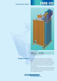
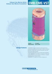
Technical Description This is a <strong>com</strong>pletely new system for SO x and the removal of solid particles<br />
occurring in exhaust gases from diesel engines and boiler operations. The<br />
main characteristic of this system is dry separation of soot and other harmful<br />
matters contained in exhaust gases with a specially designed ventilator/<br />
separator, known as VentSep. Separated solid particles pass through the<br />
bag fi lter, and are then collected in the soot collection pot. The scrubber<br />
system does not produce any sludge which would have to be disposed of at<br />
harbours. VentSep removes up to 97% of the solid particles.<br />
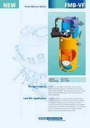
In the case of main engine scrubbing, VentSeps are placed in front of the<br />
exhaust gas boiler, which is then protected from any fouling and with no risk<br />
of fi re from soot. Soot blowers are now no longer required and the period<br />
between necessary overhauls is signifi cantly extended. After the exhaust gas<br />
boiler, clean gases - no longer containing soot but still with sulphur content -<br />
enter the heat exchanger which is placed on the top of the scrubber. The heat<br />
exchanger is cross-designed; exhaust gases that enter the heat exchanger<br />
are cooled down by the cold exhaust emitting from the scrubber. At the<br />
same time, the exhaust is being heated up with the entering gases, before<br />
passing through to the funnel. This energy-saving system is the second main<br />
characteristic of this scrubber process.<br />
For SO x removal the gases are guided via the channel that connects the heat<br />
exchanger on the top, and scrubber at the bottom. This channel is designed<br />
with nozzles, which are used to lower the temperature of the gases. This<br />
is the fi rst stage of scrubbing, i.e. removing SO x . From the bottom of the<br />
scrubber, the exhaust gases fl ow through the two - stage wet fi lter, in which<br />
more SO x is removed (up to 97%). This design can be operated in either open<br />
or closed loop confi guration.
© SAACKE GmbH · August 2012 · Content subject to alteration.<br />
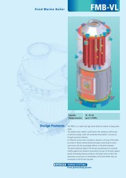
Main Engine<br />
MCR (MW)<br />
C*<br />
m<br />
A<br />
B*<br />
m<br />
A*<br />
m<br />
Dry Weight*<br />
t<br />
2 5.0 1.7 2.5 12.0<br />
4 5.5 2.1 3.0 14.0<br />
6 6.5 2.6 3.8 15.0<br />
8 7.0 3.0 4.3 16.0<br />
10 7.6 3.3 4.8 17.5<br />
12 8.0 3.6 5.2 19.0<br />
14 8.8 3.8 5.5 20.0<br />
16 9.5 4.0 6.0 21.0<br />
18 10.0 4.6 6.5 23.0<br />
20 10.5 4.8 7.0 24.0<br />
25 11.0 5.0 7.5 27.0<br />
30 12.0 6.0 8.5 35.0<br />
Boiler<br />
(Furnace)<br />
MW<br />
SAACKE GmbH · Südweststrasse 13 · 28237 Bremen · Germany · Tel.: +49 - 421 - 64 95 0 · marine@saacke.<strong>com</strong><br />
www.saacke.<strong>com</strong><br />
C*<br />
m<br />
B*<br />
m<br />
A*<br />
m<br />
Dry Weight*<br />
t<br />
1 4.70 0.65 1.40 0.69<br />
2 4.70 0.95 1.60 1.45<br />
3 4.90 1.20 1.80 2.80<br />
4 4.95 1.40 2.00 4.20<br />
5 4.95 1.50 2.20 7.10<br />
8 4.95 1.60 2.30 9.50<br />
10 5 1.7 2.5 12<br />
20 5.5 2,1 3 14<br />
30 6.5 2.6 3.8 15<br />
40 7 3 4.3 16<br />
50 7.6 3.3 4.8 17.5<br />
60 8 3.6 5.2 19<br />
70 8.8 3.8 5.5 20<br />
80 9.5 4 6 21<br />
90 10 4.6 6.5 23<br />
100 10.5 4.8 7 24<br />
125 11 5 7.5 27<br />
150 12 6 8.5 35<br />
*Dimensions A, B and C as well as weight and water volume may differ for systems with forced circulation exhaust gas economisers which use the<br />
FMB-VF-LONOX boiler as steam separator.<br />
Dimensions vary when gas is used as fuel.<br />
Exact dimensions for <strong>com</strong>mon scrubber on request.<br />
B<br />
C<br />
<strong>LMB</strong>-<strong>EGS</strong><br />
0-0750-0083-02