Insulating joint IK - RMA Pipeline Equipment
Insulating joint IK - RMA Pipeline Equipment
Insulating joint IK - RMA Pipeline Equipment

You also want an ePaper? Increase the reach of your titles
YUMPU automatically turns print PDFs into web optimized ePapers that Google loves.
<strong>RMA</strong> Kehl GmbH & Co. KG<br />
Oststrasse 17<br />
D-77694 Kehl / Germany<br />
info@rma-kehl.de<br />
www.rma-armaturen.de<br />
<strong>Insulating</strong> <strong>joint</strong> <strong>IK</strong><br />
<strong>Insulating</strong> <strong>joint</strong> <strong>IK</strong><br />
1
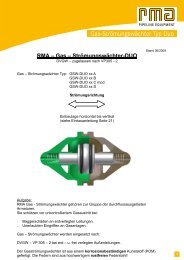
Monoblock insulating <strong>joint</strong>s<br />
<strong>Insulating</strong> <strong>joint</strong> <strong>IK</strong><br />
• are boltless, rigid pipeline components, factory-welded and ready<br />
for installation<br />
• a design which has proven sucessful throughout the world even for<br />
highest requirements<br />
• maintenance-free<br />
• suitable for underground installation without the need for special<br />
precautions or for above ground installation<br />
• absolutely no impairment due to external influences<br />
Mechanical properties<br />
Scope of application<br />
• suitable for flow media such as mineral oil, crude oil, kerosine,<br />
gasoline, propane, butane, natural gas, coal gas, ethylene, nitrogen<br />
and drinking water etc.<br />
• Media such as sour gas and oxygen necessitate special materials<br />
and design bases<br />
• please always specify the medium and operating conditions<br />
• standard versions up to maximum +80° C constant temperature<br />
• special versions for district heating pipelines up to +150° C<br />
• the excellent mechanical properties are achieved by a rigid design<br />
Materials<br />
of statically favourable form, using thermo-setting plastics free from • pipes, e.g. in accordance with DIN, API, ASTM-A and other<br />
cold flow as insulating materials standards<br />
• the welded unit provides a safe and reliable connection even over • seamless rings made of plate material or of forged quality,<br />
extremely long period of operation without the risk of the secured depending upon requirements and design calculations<br />
and locked unit loosening or separating • seals of aging-resistant material, e.g. buna N, viton, EPDM and<br />
• countless tests, prototype tests and empirical data gained during other materials.<br />
the course of many years of practical operation confirm the • insulating materials made of tried and tested materials with<br />
soundness and correctness of the complete welded design application-specific properties<br />
Electrical properties<br />
External coating<br />
• the dimensioning and practical arrangement of the insulating<br />
• unless otherwise specified, we apply PUR (Polyurethane) acc. to<br />
sections within the overall design in addition to technical production<br />
DIN 30671 as a standard<br />
factors, in conjunction with insulation materials of a suitable quality,<br />
• other types of coating are possible according to agreement and<br />
result in the ideal overall electrical behaviour of the insulating <strong>joint</strong>s<br />
purpose<br />
• large external insulating length, thus eliminating the possibility of<br />
sparkover<br />
Examples:<br />
• very good dielectric strength, substantially greater than is the case<br />
with conventional insulating flanges<br />
bitumen primer, coal tar epoxy resin and others<br />
• the average electrical resistance, measured at 1000 VDC, exceeds Internal lining<br />
40 Mohm • as per standard without lining<br />
• a decisive factor in safe operating behaviour, however, is linerarity • virtually all types of lining can be applied upon agreement,<br />
between the voltage applied and the resistive leakage current depending upon intended purpose<br />
• electrically conductive media and deposits require an appropriate<br />
Calculation<br />
internal lining<br />
• in accordance with German standards such as DIN 2470, TRBF,<br />
ASME code and other international standards, or in accordance with Tests/Inspections<br />
specific requirements<br />
• according to the agreed requirements, usually:<br />
• if no other regulations are made, the <strong>RMA</strong>-company standards<br />
(DIN-standards) are valid. Thus for the calculation and for the<br />
- a strength and tightness test with water<br />
strength characteristics of the design the working pressure, resp.<br />
- an electrical breakdown test with 5000 V/1 minute,<br />
the maximum test pressure is decisive<br />
AC, 50 Hz (both before and after the hydrostatic<br />
• additional forces such as bending moments and tensile forces etc.<br />
pressure test)<br />
must be specified by the customer<br />
- an electrical resistance test, standard 500 V. In<br />
• basically, all components of forces and force values occuring can<br />
special cases 1000 V DC<br />
be taken into consideration during design calculation<br />
- checking the material certificates<br />
• a uniform assessment, valid simultaneously for all applications and - evaluation of the destructive and non destructive tests<br />
requirements is not possible in practice<br />
- dimensional checks<br />
• depending upon the basis of the order, the tests are<br />
Scope of manufacture<br />
• unrestricted, i.e. extending beyond the data and tables g i v e n<br />
• the numerical values specified in the brochure are based upon<br />
assumed standard versions<br />
conducted either by our quality assurance<br />
department, by an official acceptance testing agency, by the<br />
customer himself or by an acceptance testing company authorized<br />
by the customer<br />
• deviations and matching to specific operating conditions may be<br />
implemented at any time<br />
Qualifications for insulating <strong>joint</strong>s<br />
• component testing in accordance with German regulations<br />
(VDTÜV 1066)<br />
• stress tests and bending tests<br />
• multifunctional prototype tests in all ranges up to 60“<br />
• and other quality assurance tests<br />
Technical modifications reserved<br />
2
DIN-standard version up to PN 100 or ANSI 600.<br />
Other sizes and pressure ratings on request.<br />
Size<br />
DN<br />
PN 10, 16 PN 25<br />
Overall Diameter Weight<br />
length<br />
Dimensions & Weight table<br />
<strong>Insulating</strong> <strong>joint</strong> <strong>IK</strong><br />
PN 40 PN 70 PN 100<br />
Overall Diameter Weight Overall Diameter Weight Overall Diameter Weight Overall Diameter Weight<br />
length<br />
length<br />
length<br />
length<br />
[mm] [inch] L [mm] DØ [mm] m [kg] L [mm] DØ [mm] m [kg] L [mm] DØ [mm] m [kg] L [mm] DØ [mm] m [kg] L [mm] DØ [mm] m [kg]<br />
25 1" 500 115 7 500 115 7 500 115 7 500 115 7<br />
40 1½" 500 115 7,5 500 115 7,5 500 115 7,5 500 115 7,5<br />
50 2" 700 140 11 700 140 11 700 140 11 700 140 11<br />
65 2½"<br />
- see Type ET<br />
700 160 16 700 160 16 700 160 16 700 160 16<br />
80 3" - Type <strong>IK</strong> on request 700 160 17 700 160 17 700 160 17 700 160 17<br />
100 4" 700 194 29 700 194 29 700 194 29 700 194 29<br />
125 5" 700 220 35 700 220 35 700 220 35 700 220 35<br />
150 6" 700 273 45 700 273 45 700 273 45 700 273 45<br />
200 8" 700 324 68 700 324 68 700 324 72 700 324 72<br />
250 10" 700 356 49 700 370 80 700 370 80 700 380 105 700 384 115<br />
300 12" 700 419 65 700 425 115 700 425 115 700 425 130 700 434 173<br />
350 14" 700 446 76 700 450 120 700 425 120 700 454 135 700 476 190<br />
400 16" 700 500 100 700 505 130 700 510 155 700 510 180 1.000 527 250<br />
450 18" 700 550 120 700 460 145 700 560 178 700 570 230 1.000 586 340<br />
500 20" 700 620 146 700 612 170 700 612 205 1.000 625 295 1.000 645 415<br />
600 24" 1.000 710 215 1.000 716 265 1.000 716 315 1.200 733 475 1.200 770 645<br />
700 28" 1.000 823 281 1.000 816 345 1.000 822 410 1.200 850 630 1.500 886 970<br />
800 32" 1.000 920 352 1.200 918 460 1.200 928 540 1.500 968 940 1.500 1.005 1.295<br />
900 36" 1.200 1.032 480 1.200 1.023 550 1.200 1.033 670 1.500 1.076 1.140 1.500 1.115 1.670<br />
1.000 40" 1.200 1.127 516 1.200 1.128 660 1.200 1.144 870 1.500 1.190 1.295 1.500 1.222 2.040<br />
1.050 42" 1.200 1.180 570 1.200 1.180 700 1.200 1.194 910 1.500 1.240 1.540 1.800 1.287 2.470<br />
1.100 44" 1.500 1.235 690 1.500 1.230 860 1.500 1.244 1.075 1.500 1.294 1.740 1.800 1.340 2.650<br />
1.200 48" 1.500 1.340 880 1.500 1.338 980 1.500 1.366 1.400 1.500 1.416 2.250 1.800 1.474 3.450<br />
larger nominal diameters and pressure ratings on request<br />
the above data refer to insulating <strong>joint</strong>s designed and manufactured in accordance with DIN-standards<br />
calculation and design in accordance with DIN 2470 Part 1 (gas up to 16 bar) and DIN 2470 Part 2 (gas over 16 bar), including TRBF 301, or on the<br />
basis of other requirements covered by the above groups<br />
safety factor S = 1,8 (F = 0,55)<br />
testing pressure, standard = 1,5-times nominal pressure or operating pressure<br />
electrical test, standard 5000 V/1minute (50 Hz), AC<br />
electrical resistance test, standard 500 V, DC<br />
please specify pipe connection dimensions and connection material when enquiring or ordering<br />
other versions and design data available on request<br />
beside the general design in accordance with DIN-standard, ASME-code or other standards can also be taken as a basis, depending on the<br />
requirements for welding or testing<br />
<br />
<br />
<br />
<br />
<br />
<br />
<br />
<br />
<br />
<br />
3
ASME-standard version up to ANSI Class 600.<br />
Other sizes and pressure ratings on request.<br />
Size<br />
DN<br />
Overall<br />
length<br />
Diameter Weight<br />
Dimensions & Weight table<br />
ANSI 150 ANSI 300 ANSI 400<br />
Overall<br />
length<br />
Diameter Weight Overall<br />
length<br />
<strong>Insulating</strong> <strong>joint</strong> <strong>IK</strong><br />
Diameter Weight Overall<br />
length<br />
ANSI 600<br />
Diameter Weight<br />
[mm] [inch] L [mm] DØ [mm] m [kg] L [mm] DØ [mm] m [kg] L [mm] DØ [mm] m [kg] L [mm] DØ [mm] m [kg]<br />
25 1" 500 114 7 500 114 7 500 114 7<br />
40 1½" 500 114 7,5 500 114 7,5 500 114 7,5<br />
50 2" - see Type ET<br />
700 140 11 700 140 11 700 140 11<br />
65 2½" - Type <strong>IK</strong> on request 700 160 16 700 160 16 700 160 16<br />
80 3" 700 160 17 700 160 17 700 160 17<br />
100 4" 700 194 29 700 194 29 700 194 29<br />
125 5" 700 220 35 700 220 35 700 220 38<br />
150 6" 700 273 45 700 273 45 700 273 58<br />
200 8" 700 324 74 700 324 84 700 324 86<br />
250 10" 700 370 80 700 380 113 700 380 113 700 384 138<br />
300 12" 700 425 115 700 425 148 700 425 148 1.000 434 234<br />
350 14" 700 450 120 700 454 150 1.000 454 178 1.000 476 262<br />
400 16" 700 505 136 1.000 510 205 1.000 510 252 1.000 527 296<br />
450 18" 700 560 152 1.000 560 252 1.000 570 314 1.200 586 420<br />
500 20" 1.000 612 235 1.000 612 328 1.200 625 383 1.200 645 530<br />
600 24" 1.000 716 283 1.000 722 400 1.200 733 550 1.200 770 750<br />
700 28" 1.000 816 355 1.200 828 565 1.500 850 786 1.500 886 1.120<br />
800 32" 1.200 918 492 1.500 941 860 1.500 968 1.095 1.800 1.005 1.670<br />
900 36" 1.500 1.023 690 1.500 1.046 1.085 1.800 1.076 1.460 1.800 1.115 2.120<br />
1.000 40" 1.500 1.128 815 1.500 1.162 1.345 1.800 1.190 1.685 1.800 1.222 2.620<br />
1.050 42" 1.800 1.180 960 1.800 1.212 1.575 2.000 1.240 2.085 2.200 1.287 3.230<br />
1.100 44" 1.800 1.230 1.025 1.800 1.271 1.685 2.000 1.294 2.237 2.200 1.340 3.473<br />
1.200 48" 2.000 1.338 1.240 2.000 1.384 2.150 2.000 1.416 3.100 2.500 1.474 4.730<br />
larger nominal diameters and pressure ratings on request<br />
the above data refer to insulating <strong>joint</strong>s designed in accordance with ASME Code Section VIII, Div. 1. Design factor F=0.5, other factors are possible<br />
testing pressure = 1.5 times design pressure or as specified<br />
electrical test, standard 5000 V/1 minute (50 Hz), AC<br />
electrical resistance test, standard 500 V, DC<br />
please specify the pipe connection dimensions and connection material when enquiring or ordering<br />
other versions, design data, calculation and design standards on request<br />
<br />
<br />
<br />
<br />
<br />
<br />
<br />
3
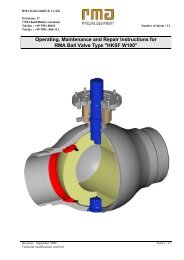
Further versions<br />
<strong>Insulating</strong> <strong>joint</strong> with flange connection on one or both sides.<br />
<strong>Insulating</strong> <strong>joint</strong> with connection for ex-proof spark gaps.<br />
<strong>Insulating</strong> <strong>joint</strong> <strong>IK</strong><br />
5
Design with special internal lining up to the O-ring groove. For strongly<br />
electrically conductive media e.g. water, sea water, salt water, etc.<br />
Inside lining on one ore two sides, depending on requirements on site.<br />
Design for highest requirements especially<br />
for large sizes and high pressure ratings.<br />
<strong>Insulating</strong> <strong>joint</strong> <strong>IK</strong><br />
Up to DN 300 inclusive, PN 25-100 according to DIN-standard<br />
design with lip seal, manufactured in series.<br />
6