Manage wiring complexity with Signal Harnesses Summary - Altium
Manage wiring complexity with Signal Harnesses Summary - Altium
Manage wiring complexity with Signal Harnesses Summary - Altium

Create successful ePaper yourself
Turn your PDF publications into a flip-book with our unique Google optimized e-Paper software.
<strong>Summary</strong><br />
November 2007<br />
Author: Phil Loughhead<br />
IN THE WORKSHOP – Tip #17<br />
<strong>Manage</strong> <strong>wiring</strong> <strong>complexity</strong> <strong>with</strong> <strong>Signal</strong><br />
<strong>Harnesses</strong><br />
<strong>Signal</strong> harnesses expands on bus and wire connectivity by letting you<br />
assemble logical groupings of any signals, greatly simplifying the <strong>wiring</strong> traffic,<br />
enhancing readability, and streamlining the structure of your schematic.<br />
<strong>Altium</strong> Designer 6 introduces a new way of establishing connectivity and reducing schematic <strong>complexity</strong> – called <strong>Signal</strong><br />
<strong>Harnesses</strong>. <strong>Signal</strong> harnesses extend on bus and wire connectivity by allowing you to assemble logical groupings of any<br />
signals, greatly simplifying the <strong>wiring</strong> traffic, enhancing readability, and potentially streamlining the structure of your<br />
schematic design.<br />
Using signal harnesses you can create and manipulate higher levels of abstraction between sub-circuits, effectively<br />
allowing for more complex designs to be represented <strong>with</strong> simpler drawings.<br />
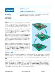
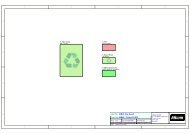
Figure 1 .<strong>Harnesses</strong> carry multiple signals and can include both buses and wires, which are grouped and then<br />
referenced as a single entity. This multi-signal connection is called a <strong>Signal</strong> Harness.<br />
Using <strong>Signal</strong> <strong>Harnesses</strong><br />
To use a harness as a container for nets and / or buses, you simply wire each net and bus into a Harness Entry in a<br />
Harness Connector. Each net or bus is identified in the harness by the name of the Harness Entry that you wire it to – it<br />
is that name (not the order of the Entries) that is used by <strong>Altium</strong> Designer to establish connectivity throughout the design.<br />
Note that the Harness Entry name is not used to name the net, unless you name the <strong>Signal</strong> Harness itself.<br />
The signals are then carried across the sheet using a signal harness line, connecting to another harness connector on<br />
the same sheet, or to a sheet entry or port so it can connect to another schematic.<br />
Reusing a <strong>Signal</strong> Harness<br />
You can think of a <strong>Signal</strong> Harness as being like a physical cable. NewHarness, shown in Figure 1, would be the 3 wires<br />
(COL, CRS, and TXEN), and the twisted bundle of 4 wires (RXD[3..0]). And just like a cable, the harness does not care<br />
what signals you ultimately run through it. This means you can use the same signal harness multiple times in your design.<br />
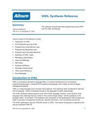
Figure 2 shows the Harness JTAG being used twice.<br />
© 2007 <strong>Altium</strong> Limited <strong>Manage</strong> <strong>wiring</strong> <strong>complexity</strong> <strong>with</strong> <strong>Signal</strong> <strong>Harnesses</strong> Page 1 of 4
Nested <strong>Harnesses</strong><br />
Figure 2. <strong>Harnesses</strong> can be nested together <strong>with</strong><br />
other nets, buses and harness, into a parent harness.<br />
The Harness Definition file shows the definition of<br />
JTAG, and also the parent Harness Connector,<br />
HARDSOFT_JTAG.<br />
<strong>Harnesses</strong> can also be nested, that is, a harness can become part of another harness. Figure 2 shows nested harnesses,<br />
where the 2 JTAG signal harnesses become part of the parent signal harness, HARDSOFT_JTAG.<br />
<strong>Harnesses</strong> are nested by placing and <strong>wiring</strong> in the same way as wires and buses. Note that the actual <strong>Signal</strong> Harness<br />
line is optional.<br />
How the Nets are named<br />
If the <strong>Signal</strong> Harness is not named, that is you have not placed a Netlabel on it, then the names assigned to the<br />
individual nets and bus elements are used to identify the nets. Since <strong>Altium</strong> Designer supports changing net names as<br />
you traverse the design hierarchy, the final net name is determined by the naming preferences enabled in the Netlist<br />
Options section of the Project Options dialog.<br />
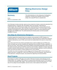
Figure 3. <strong>Signal</strong> <strong>Harnesses</strong> can greatly<br />
simplify the readability of a design. This<br />
image shows the top sheet from the same<br />
design, the upper version using Nets and<br />
Buses, the lower one using <strong>Signal</strong><br />
<strong>Harnesses</strong>. The extra Nets and buses on the<br />
right hand side of the upper sheet are<br />
needed to specify user-defined PCB Net<br />
Classes, these can be created automatically<br />
from named <strong>Signal</strong> <strong>Harnesses</strong>.<br />
If a <strong>Signal</strong> Harness is named, <strong>Altium</strong><br />
Designer adopts a different approach to<br />
managing the names of the nets that flow<br />
throw it. In this case, <strong>Altium</strong> Designer will<br />
name each net in the format<br />
HarnessName.HarnessEntryName, and will<br />
no longer rely on the names of the nets and<br />
buses connected to it. Enable the Higher<br />
Level Names Takes Priority option for this<br />
naming scheme to be applied consistently<br />
across all named <strong>Harnesses</strong>. If this<br />
approach is used, choose Harness names<br />
and Harness Entry names that work together<br />
to create suitable net names<br />
© 2007 <strong>Altium</strong> Limited <strong>Manage</strong> <strong>wiring</strong> <strong>complexity</strong> <strong>with</strong> <strong>Signal</strong> <strong>Harnesses</strong> Page 2 of 4
Creating a PCB Class for the nets in a Harness<br />
An advantage of naming your <strong>Signal</strong> <strong>Harnesses</strong> is that you can get <strong>Altium</strong> Designer to automatically create PCB net<br />
classes when the design is transferred to the PCB editor, by enabling the option in the Class Generation tab of the<br />
Project Options dialog.<br />
Inside a <strong>Signal</strong> Harness<br />
The set of nets / buses that a <strong>Signal</strong> Harness can carry is specified by a Harness Definition. Whenever you place or edit<br />
a Harness Connector, <strong>Altium</strong> Designer automatically creates / edits a matching Harness Definition, in a<br />
Harness Definition file (*.Harness).<br />
The Harness Definition looks like:<br />
NewHarness=COL,CRS,RXD[3..0],TXEN<br />
Here, the Harness Type NewHarness, includes the nets, COL, CRS, and TXEN. It also includes the bus RXD[3..0]. Note<br />
that the order of the nets and buses in the Harness Definition is not important (they are automatically sorted<br />
alphabetically) – it is the Harness Entry names that are important.<br />
If NewHarness was nested <strong>with</strong>in a parent harness, it would look something like:<br />
ParentHarness={FirstEntryName:NewHarness},{SecondEntryName:AnotherHarness},SomeNet<br />
Note how the nested harness is encased <strong>with</strong>in curly braces and associated <strong>with</strong> its Harness Entry. Any wires or buses<br />
going into the parent harness are referenced in the standard way.<br />
A Harness connects from a sub-sheet to the parent sheet symbol using the standard <strong>Altium</strong> Designer Port-to-matching-<br />
Sheet Entry combination. The Harness does not rely on the naming of this pair, instead it uses the Harness Type<br />
property of the Port / Sheet Entry pair to establish cross sheet harness connectivity. The Port is automatically assigned<br />
the HarnessType when it is attached to a Harness line or Harness Connector. The Harness Type of the Sheet Entry can<br />
be user-defined if the design is hierarchical, keep an eye on these if you are manually building a hierarchal design that<br />
uses harnesses.<br />
A <strong>Signal</strong> Harness <strong>with</strong>out the Harness Connector<br />
You can also define and use <strong>Signal</strong> <strong>Harnesses</strong> <strong>with</strong>out placing Harness Connectors. In this case, you must create and<br />
manage the Harness Definitions yourself. You should also lock these Harness Definitions (by adding the Locked;<br />
keyword to the Harness Definition), so that <strong>Altium</strong> Designer does not attempt to modify or delete them as it automatically<br />
manages Harness Definitions created by the presence of Harness Connectors.<br />
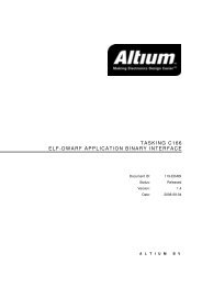
Figure 4. <strong>Signal</strong> <strong>Harnesses</strong> can be created <strong>with</strong>out Harness Connectors. Note that the Harness Definition must be either<br />
typed in manually, or auto-created by placing and defining a Harness Connector, and then deleting the Harness<br />
Connector.<br />
Techniques for building a <strong>Signal</strong> Harness<br />
If you are building up a design, the Place Predefined Harness Connector command gives easy access to all the<br />
harnesses currently available in <strong>Altium</strong> Designer. If you are modifying an existing design to replace wires and buses <strong>with</strong><br />
<strong>Signal</strong> <strong>Harnesses</strong>, the easiest way to work is to use <strong>Altium</strong> Designer’s Smart Paste feature. Using this, you can select<br />
sets of existing nets or ports, copy or cut them, and Smart Paste in a complete Harness.<br />
© 2007 <strong>Altium</strong> Limited <strong>Manage</strong> <strong>wiring</strong> <strong>complexity</strong> <strong>with</strong> <strong>Signal</strong> <strong>Harnesses</strong> Page 3 of 4
Figure 5. Use the Smart Paste feature to quickly build <strong>Signal</strong> <strong>Harnesses</strong>.<br />
Once the old sheet entries and wires / buses have been deleted from the parent sheet, new Sheet Entries can be<br />
added in the parent sheet symbol using the Synchronize Sheet Entries and Ports command (right click on the<br />
Sheet Symbol and select the command from the Sheet Symbol Actions sub-menu). Something to keep in mind, if<br />
you are manually adding and configuring Sheet Entries for your <strong>Harnesses</strong>, <strong>Altium</strong> Designer will always attempt to set<br />
the HarnessType attribute if it can detect a <strong>Signal</strong> Harness, so it is more efficient to place the Sheet Entry last so it<br />
touches an existing <strong>Signal</strong> Harness. If you place the Sheet Entry first and then the <strong>Signal</strong> Harness, you must set the<br />
HarnessType attribute. If you use the Synchronize Sheet Entries and Ports command, this is set automatically.<br />
© 2007 <strong>Altium</strong> Limited <strong>Manage</strong> <strong>wiring</strong> <strong>complexity</strong> <strong>with</strong> <strong>Signal</strong> <strong>Harnesses</strong> Page 4 of 4