9.1.Thermal Insulation of Torpedo Cars - Pyrotek
9.1.Thermal Insulation of Torpedo Cars - Pyrotek
9.1.Thermal Insulation of Torpedo Cars - Pyrotek

Create successful ePaper yourself
Turn your PDF publications into a flip-book with our unique Google optimized e-Paper software.
THERMAL INSULATION OF TORPEDO CARS<br />
Jiang Hua, Bao Ji, and Li Jun, Baoshan Iron and Steel, Shanghai, 201900,<br />
P.R. China<br />
Song Li Ming, Northeastern Univ., No. 11 Sanxiang, Wenhua Rd. Shenyang,<br />
Liaonning, P.R. China<br />
En-Sheng Chen, Thermomechanical Designs, 6111 FM 1960 West, # 107,<br />
Houston, Texas 77069, USA<br />
Marc-H. Fréchette, <strong>Pyrotek</strong>, 2400 Lemire Blvd. Drummondville, Quebec,<br />
J2B 6X9, Canada<br />
Abstract<br />
Baoshan Iron & Steel operates a<br />
fleet <strong>of</strong> seventy (70) 320 tonne<br />
torpedo cars. During liquid iron<br />
transportation, they experience<br />
significant heat loss through their<br />
refractory linings. Therefore, a layer<br />
<strong>of</strong> high strength insulating material<br />
behind a safety lining was<br />
considered. This paper summarizes<br />
a study evaluating the thermal<br />
behavior <strong>of</strong> the refractory lining with<br />
and without this insulating layer. A<br />
finite-element thermal analysis was<br />
conducted, with representative<br />
modeling <strong>of</strong> material properties and<br />
processing conditions. It covered the<br />
main process steps, including the<br />
charging at the blast furnace, the<br />
residence time, the different<br />
treatments, emptying at the BOF<br />
shop, and idling time. The benefits <strong>of</strong><br />
using the insulation layer, in terms <strong>of</strong><br />
heat conservation, lower shell<br />
temperatures, the improvement <strong>of</strong><br />
liquid iron temperatures, and better<br />
heat-flow regulation, are quantified.<br />
KEYWORDS: Ironmaking, <strong>Torpedo</strong><br />
Car, heatloss, liquid temperature,<br />
and simulation.<br />
INTRODUCTION<br />
In recent years, at Baoshan, the use<br />
<strong>of</strong> high-conductivity ASC brick for<br />
torpedo car linings, result in high<br />
shell temperatures, high heat losses<br />
through the lining system,<br />
consequential degradation <strong>of</strong> the<br />
shell strength and significant loss <strong>of</strong><br />
temperature <strong>of</strong> the liquid iron. While<br />
extra lining insulation is necessary,<br />
the proper selection <strong>of</strong> insulating<br />
materials is vital to the linings<br />
integrity and stability. A low density<br />
insulating board, which usually<br />
provides good insulation, may have<br />
low strength and experience severe<br />
crushing upon lining expansion. A<br />
proper balance between thermal<br />
properties and mechanical strength<br />
requires careful evaluation <strong>of</strong> an<br />
insulating board employed in a<br />
specific T-Car lining shell system.<br />
This study evaluated the thermal<br />
behavior <strong>of</strong> a torpedo car lining using<br />
a dense, high-strength insulating<br />
board behind the safety lining taking
into consideration the two-stage<br />
chemical treatment. The justification<br />
<strong>of</strong> using the board had to be based<br />
on achieving desirable shell<br />
temperatures and improving liquid<br />
metal temperatures while<br />
maintaining its lining integrity as well<br />
as its stability under a typical<br />
operation during its complete cycle.<br />
TORPEDO CAR CONFIGURATION<br />
AND OPERATION<br />
Baoshan Iron and Steel Co. Ltd. are<br />
operating a fleet <strong>of</strong> seventy 320<br />
tonne torpedo cars and each car is<br />
lined with multi-layers <strong>of</strong> refractory<br />
materials to protect the shell from the<br />
liquid iron. The previous current<br />
refractory practice is summarized in<br />
Table 1.<br />
Refractory Materials<br />
ASC Brick<br />
(5/10% SiC +<br />
10/15°C)<br />
65% Al2O3 Castable<br />
50% Al2O3 Brick<br />
Refractory Materials<br />
ASC Brick<br />
(75%Al2O3&22%SiC+C)<br />
65% Al2O3 Castable<br />
50% Al2O3 Brick<br />
Slag<br />
Zone<br />
275 mm<br />
20 mm<br />
70 mm<br />
Cylinder<br />
275 mm<br />
20 mm<br />
70 mm<br />
Impact<br />
Pad<br />
382<br />
mm<br />
20 mm<br />
70 mm<br />
Cones<br />
275<br />
mm<br />
20 mm<br />
70 mm<br />
Table 1 : Previous Refractory Practice<br />
Each vessel averages 2.6 cycles/day<br />
(9 hours/cycle). The cycle begins at<br />
the Blast Furnace where the liquid<br />
metal is poured into the torpedo car.<br />
The hot metal resides in the car for<br />
approximately 4.5 hours for<br />
transportation and treatment. After<br />
1.5 hours, a two-stage chemical<br />
treatment is conducted. Each stage<br />
<strong>of</strong> the treatment lasts for about 30<br />
minutes. During the residence<br />
period, they are not using a lid to<br />
cover the mouth <strong>of</strong> the vessel<br />
therefore, a significant heat loss is<br />
apparent. After it reaches the BOF<br />
Shop, the vessel is emptied into a<br />
transfer ladle for BOF charging.<br />
Thereafter, the empty car returns to<br />
the Blast Furnace Cast House for the<br />
next charge. The average idling time<br />
is 4.5 hours/cycle.<br />
During the residence time,<br />
substantial heat loss occurs through<br />
the refractory lining, resulting in<br />
significant temperature reduction <strong>of</strong><br />
the liquid iron. During the idling time,<br />
the heat loss, through and from the<br />
refractory lining contribute to further<br />
reduce the overall lining<br />
temperatures. This results, after the<br />
subsequent charge, in a sudden heat<br />
loss (Heatflow) from the iron bath<br />
into the refractory lining. This<br />
phenomenon is conducive to the<br />
increase <strong>of</strong> the shell temperatures to<br />
such a level that it becomes a major<br />
concern as the lining is thinning<br />
down toward the later stage <strong>of</strong> the<br />
campaign.<br />
INSULATING MATERIALS<br />
To solve the above thermal problem,<br />
an improved lining design using a<br />
high density insulating board, 16mm
thickness was implemented. In order<br />
to reduce heat loss and shell<br />
temperature while maintaining vessel<br />
capacity, we have reduced the safety<br />
lining thickness to accommodate the<br />
insulating layer. The properties <strong>of</strong> the<br />
insulating board are summarized in<br />
table 2.<br />
Chemical<br />
Composition (%) :<br />
SiO2<br />
MgO<br />
P2O5<br />
Fe2O3<br />
Al2O3<br />
Bulk Density<br />
(g/cm 3 )<br />
Apparent Porosity<br />
(%)<br />
Cold Crushing<br />
Strength (MPa)<br />
Thermal<br />
Conductivity<br />
(W/°K.m)<br />
36<br />
24.6<br />
11.8<br />
8.7<br />
6.8<br />
1.3 +-<br />
6%<br />
53.5<br />
15.1<br />
0.31 @<br />
600°C<br />
Table 2 : Properties <strong>of</strong> the Insulating<br />
Board.<br />
MODELING AND ANALYSES<br />
To evaluate the effectiveness <strong>of</strong> the<br />
current design with the insulating<br />
layer, a series <strong>of</strong> thermal analyses<br />
was conducted. It adopted the<br />
thermal analysis capability<br />
developed exclusively for hightemperature<br />
lining-shell systems and<br />
verified with field data over years.<br />
The analyses employ 3-D finiteelement<br />
geometry modeling,<br />
temperature-dependent material<br />
modeling, thermal boundary<br />
modeling, and transient analyses. A<br />
paper in the related areas <strong>of</strong> heattransfer<br />
analyses is also presented<br />
in this symposium.<br />
Figures 1 and 2, show the 3-D<br />
geometry models on a quarter <strong>of</strong> the<br />
torpedo car (assumed symmetry)<br />
developed for the car with a new<br />
lining condition and a worn lining<br />
condition, respectively. Thermal<br />
loads were properly applied to the<br />
various boundaries <strong>of</strong> the torpedo<br />
car and it's lining to simulate the<br />
actual operating conditions, with the<br />
following specifications:<br />
(1) The residence period lasted<br />
for 4.5 hours. The initial iron<br />
temperature right after the<br />
iron charging was 1560°C.<br />
After 1.5 hours entering the<br />
residence period, the two<br />
stage chemical treatment<br />
started. The first stage lasted<br />
for 30 minutes and reduced<br />
the average iron temperature<br />
by 1°C/min and the second<br />
one also lasted for 30 minutes<br />
and reduced the average iron<br />
temperature by 1.75°C/min.<br />
The mouth opening would<br />
allow heat loss into the<br />
ambient environment.<br />
(2) During the residence period,<br />
the liquid iron did not fully fill<br />
the interior space <strong>of</strong> the<br />
torpedo car. High thermal<br />
radiation was considered as<br />
the heat transfer mechanism<br />
in the space between the<br />
lining and the liquid iron.
(3) After the resident period, the<br />
liquid iron was tapped out at a<br />
BOF site. The torpedo car<br />
then became empty for 4.5<br />
hours.<br />
(4) The exterior surface <strong>of</strong> the<br />
shell was considered a<br />
convective and<br />
radiative thermal boundary<br />
with an ambient temperature<br />
<strong>of</strong> 25°C.<br />
Figure 1 : Finite element model / new<br />
lining<br />
Figure 2 : Finite element model /<br />
worn lining<br />
For each case with a specific<br />
combination <strong>of</strong> lining design (with or<br />
without insulating board) and<br />
working lining condition (new or worn<br />
linings), a multi-step, nonlinear heat<br />
transfer analysis was conducted. An<br />
initial steady-state condition was first<br />
established, followed by an iterative<br />
process to ensure the average<br />
interior temperatures during the<br />
residence period converged to the<br />
average surface temperatures <strong>of</strong> the<br />
liquid iron. During the empty period,<br />
the iteration further converged the<br />
average interior temperatures to the<br />
average lining inside-face<br />
temperatures. This iterative process,<br />
although time consuming would<br />
provide a realistic heat transfer<br />
simulation for all components. The<br />
heat loss caused by the chemical<br />
treatment was modeled as a heat<br />
sink in the liquid iron. The average<br />
heat loss rates were imposed based<br />
on the temperature drops specified<br />
previously.<br />
THERMAL BEHAVIOR DURING<br />
RESIDENCE TIME<br />
The use <strong>of</strong> the insulating board was<br />
expected to significantly improve the<br />
liquid iron temperatures during the<br />
iron transport through heat-loss<br />
reduction. Therefore, by evaluating<br />
the heat loss and temperature in the<br />
liquid iron, we could quantify and<br />
contrast for the benefit <strong>of</strong> using the<br />
insulating board.<br />
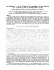
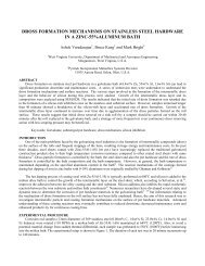
Figures 3 to 4 shows the average<br />
liquid-iron temperatures for the newand<br />
worn-lining cases during the<br />
residence period. Figures 5 to 6<br />
shows heat losses during Residence<br />
Period for the new and worn lining.
Temperature (oC)<br />
1600<br />
1580<br />
1560<br />
1540<br />
1520<br />
1500<br />
1480<br />
1460<br />
1440<br />
1420<br />
1400<br />
1380<br />
with Board<br />
without Board<br />
1360<br />
0 1 2 3 4 5<br />
Time after Charge (Hours)<br />
Figure 3 : Average liquid Iron<br />
temperatures / new lining.<br />
As these figures show, during the<br />
early stage, heat escapes fast from<br />
the liquid iron into the much cooler<br />
lining, resulting in a fast drop <strong>of</strong><br />
liquid-iron temperatures. Afterward,<br />
the heat-loss rates gradually stabilize<br />
with steady heat flows through the<br />
lining and the mouth opening, until<br />
the chemical treatment starts.<br />
Temperature (oC)<br />
1600<br />
1580<br />
1560<br />
1540<br />
1520<br />
1500<br />
1480<br />
1460<br />
1440<br />
1420<br />
1400<br />
1380<br />
without Board<br />
with Board<br />
1360<br />
0 1 2 3 4 5<br />
Time after Charge (Hours)<br />
Figure 4 : Average liquid Iron<br />
temperatures/ worn lining<br />
During the chemical treatment, the<br />
liquid-iron temperatures drop<br />
substantially. This brings the liquidiron<br />
temperatures to a close range <strong>of</strong><br />
the temperatures near the lining hot<br />
face. Therefore, the heat transfer<br />
between the liquid iron and the lining<br />
reduces significantly. This results in<br />
a much slower temperature<br />
reduction in the liquid iron right after<br />
the treatment. However, toward the<br />
later stage <strong>of</strong> the residence period,<br />
the temperature reduction rates pick<br />
up again.<br />
Heat Loss (10 9 Joule)<br />
28<br />
26<br />
24<br />
22<br />
20<br />
18<br />
16<br />
14<br />
12<br />
10<br />
8<br />
6<br />
4<br />
2<br />
without Board<br />
with Board<br />
0<br />
0 1 2 3 4 5<br />
Time after Charge (Hours)<br />
Figure 5 : Heat losses during residence<br />
period / new lining<br />
Compared with the cases without the<br />
use <strong>of</strong> an insulating board, the<br />
introduction <strong>of</strong> the board can<br />
significantly reduce the heat loss<br />
through the refractory lining system<br />
and thus maintain higher liquid-iron<br />
temperatures and lower shell<br />
temperatures. On the average, the
liquid-iron temperatures at the end <strong>of</strong><br />
the residence time can be increased<br />
by 23 and 26°C for the new and<br />
worn lining cases, respectively. The<br />
heat-loss reduction can achieve 12.8<br />
and 14.0% for the new and worn<br />
lining cases, respectively. The<br />
average shell temperatures are also<br />
reduced with lower levels <strong>of</strong><br />
temperature variation. This may help<br />
reduce the levels <strong>of</strong> local stress<br />
development. The maximum<br />
temperatures in the insulating board<br />
are generally below 800°C, even in<br />
the worn-lining case. This<br />
temperature level should be within<br />
the application rages <strong>of</strong> the board<br />
and thus helps maintain reasonable<br />
strength and integrity <strong>of</strong> the board.<br />
Heat Loss (10 9 Joule)<br />
28<br />
26<br />
24<br />
22<br />
20<br />
18<br />
16<br />
14<br />
12<br />
10<br />
8<br />
6<br />
4<br />
2<br />
without Board<br />
0<br />
0 1 2 3 4 5<br />
Time after Charge (Hours)<br />
with Board<br />
Figure 6 : Heat losses during<br />
residence period / worn lining<br />
Based on thermal analyses and the<br />
behavioral evaluation, the benefits <strong>of</strong><br />
using the insulating board for the<br />
torpedo car are defined and found<br />
quite appreciable. Therefore, the<br />
board was recommended for field<br />
installation and implementation.<br />
INSTALLATION<br />
The torpedo lining consists <strong>of</strong><br />
rectangular shapes (416 x 101 x<br />
16mm) and conical shapes (416 x<br />
(101/91) x 16mm). Baoshan used<br />
the rectangular shapes in the<br />
horizontal cylinder and a ratio <strong>of</strong><br />
rectangular and conical shapes in<br />
the cones.<br />
The first installation took place in<br />
April 2002. For the first lining,<br />
Baoshan installed the insulating<br />
layer in the entire vessel, continued<br />
with the installation <strong>of</strong> the safety<br />
lining and completed with the wear<br />
lining. They proceeded as follow:<br />
• Horizontal cylinder: Starting<br />
from both ends, they worked<br />
towards the center to make<br />
one cut to close the last ring.<br />
They worked with 2 crews.<br />
• Cones: They worked in both<br />
cones simultaneously with<br />
one crew in each cone.<br />
Each crew consists <strong>of</strong> two brick<br />
masons.<br />
They have used an air set refractory<br />
cement to glue the tiles against the<br />
shell as well as in all horizontal and<br />
vertical joints.<br />
However, for the future installations,<br />
Baoshan will include the insulating<br />
board to their regular installation<br />
practice. They will install all the<br />
different refractory layers in the lower<br />
section (cylinder and cones) <strong>of</strong> the<br />
vessel before installing the<br />
scaffolding and completing with the<br />
installation <strong>of</strong> the
different refractory layers in the<br />
upper section <strong>of</strong> the vessel.<br />
PRELIMINARY RESULTS<br />
After adequate pre-heating, the first<br />
insulated torpedo car went in<br />
service. Baoshan have monitored<br />
the liquid iron temperature in the<br />
insulated torpedo car as well as in a<br />
non-insulated torpedo car for<br />
comparison purposes.<br />
The first series <strong>of</strong> measurements<br />
were taken at the BOF, after 151<br />
cycles (or 42,300 tonnes) and they<br />
have noticed an improvement <strong>of</strong> the<br />
liquid iron temperature ranging from<br />
20°C to 25°C.<br />
When we refer to the average<br />
campaign <strong>of</strong> 600,000 tonne, we<br />
recognize that the first set <strong>of</strong><br />
measurements were taken at an<br />
early stage in the life <strong>of</strong> the torpedo<br />
car. However, Baoshan will be taking<br />
other measurements on a regular<br />
basis throughout the campaign to<br />
confirm the preliminary results.<br />
SUMMARY AND CONCLUSIONS<br />
An analysis study was conducted to<br />
evaluate the thermal behavior <strong>of</strong> a<br />
torpedo car using a dense, highstrength<br />
insulating board behind the<br />
safety lining. Based on the analysis<br />
results, it clearly demonstrates that<br />
the insulating board can:<br />
1. Substantially reduce the shell<br />
temperatures after the wear<br />
lining worn down.<br />
2. Reduce the heat loss from hot<br />
liquid iron and improve liquid<br />
iron temperature at the end <strong>of</strong><br />
residence time.<br />
The trial preliminary results, at<br />
Baoshan, support the use <strong>of</strong> the<br />
insulating board for the torpedo car<br />
application with similar lining designs<br />
and operational practice.<br />
We wish to extend our gratitude<br />
toward Mr. Jiang Hua, Mr. Bao Ji,<br />
and Mr. Li Jun <strong>of</strong> Baoshan and Song<br />
Li Ming <strong>of</strong> Northeastern University<br />
for their cooperation and contribution<br />
for which this trial would not have<br />
been possible.<br />
REFERENCES<br />
(1) E.S Chen and M.H. Fréchette,<br />
"Thermal and Thermomechanical<br />
Evaluation <strong>of</strong> High-Strength<br />
<strong>Insulation</strong> in Steelmaking Ladle",<br />
ISS Steelmaking Conference,<br />
1996.<br />
(2) E.S. Chen, "Thermal Analysis<br />
<strong>of</strong> Refractory Lining Systems", 4 th<br />
International Symposium on<br />
Refractories, 2003.