Improving Performance in Continuous Casting - Pyrotek
Improving Performance in Continuous Casting - Pyrotek
Improving Performance in Continuous Casting - Pyrotek

You also want an ePaper? Increase the reach of your titles
YUMPU automatically turns print PDFs into web optimized ePapers that Google loves.
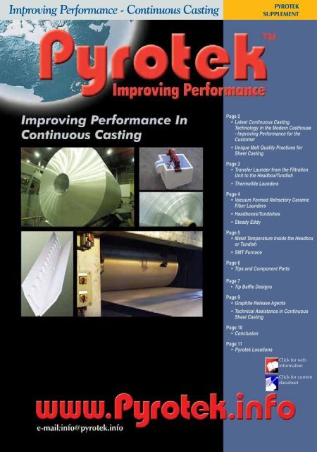
<strong>Improv<strong>in</strong>g</strong> <strong>Performance</strong> - Cont<strong>in</strong>uous Cast<strong>in</strong>g<br />
<strong>Improv<strong>in</strong>g</strong> <strong>Performance</strong> - Cont<strong>in</strong>uous Cast<strong>in</strong>g<br />
pyrotek<br />
supplement<br />
pyrotek<br />
supplement<br />
Page 2<br />
• Latest Cont<strong>in</strong>uous Cast<strong>in</strong>g<br />
Technology <strong>in</strong> the Modern Casthouse<br />
- <strong>Improv<strong>in</strong>g</strong> <strong>Performance</strong> for the<br />
Customer<br />
• Unique Melt Quality Practices for<br />
Sheet Cast<strong>in</strong>g<br />
Page 3<br />
• Transfer Launder from the Filtration<br />
Unit to the Headbox/Tundish<br />
• Thermollite Launders<br />
Page 4<br />
• Vacuum Formed Refractory Ceramic<br />
Fiber Launders<br />
• Headboxes/Tundishes<br />
• Steady Eddy<br />
Page 5<br />
• Metal Temperature Inside the Headbox<br />
or Tundish<br />
• SMT Furnace<br />
Page 6<br />
• Tips and Component Parts<br />
Page 7<br />
• Tip Baffle Designs<br />
Page 9<br />
• Graphite Release Agents<br />
• Technical Assistance <strong>in</strong> Cont<strong>in</strong>uous<br />
Sheet Cast<strong>in</strong>g<br />
Page 10<br />
• Conclusion<br />
Page 11<br />
• <strong>Pyrotek</strong> Locations<br />
Click for web<br />
<strong>in</strong>formation<br />
Click for current<br />
datasheet
<strong>Improv<strong>in</strong>g</strong> <strong>Performance</strong> - Cont<strong>in</strong>uous Cast<strong>in</strong>g<br />
Jonathan Prebble,<br />
Manager of<br />
Alum<strong>in</strong>ium Process<br />
Technology<br />
<strong>Pyrotek</strong> has<br />
the expertise,<br />
technology,<br />
experience<br />
and the<br />
global<br />
resources to<br />
maximize the<br />
performance<br />
of your<br />
cont<strong>in</strong>uous<br />
sheet cast<strong>in</strong>g<br />
systems.<br />
Page 2<br />
LATEST ConT<strong>in</strong>uouS<br />
CAST<strong>in</strong>g TECHnoLogY <strong>in</strong><br />
THE MoDERn CASTHouSE<br />
improv<strong>in</strong>g <strong>Performance</strong> For The<br />
Customer<br />
This is the fifth <strong>Pyrotek</strong> article <strong>in</strong> a series on<br />
improv<strong>in</strong>g casthouse performance written<br />
for Alum<strong>in</strong>ium <strong>in</strong>ternational Today (AiT).<br />
The previous <strong>Pyrotek</strong> articles have <strong>in</strong>cluded<br />
improv<strong>in</strong>g performance <strong>in</strong>: Furnace Melt<br />
Treatment; Casthouse Furnace Build<strong>in</strong>g and<br />
Repair; the Degass<strong>in</strong>g Process; the Filtration<br />
Process, and Slab Cast<strong>in</strong>g Processes.<br />
Please see the previous articles <strong>in</strong> the AiT<br />
Series at www.pyrotek.<strong>in</strong>fo/alum<strong>in</strong>ium.<br />
This article br<strong>in</strong>gs us to the cont<strong>in</strong>uous<br />
sheet cast<strong>in</strong>g operation. It is advisable to<br />
review <strong>Pyrotek</strong>’s previous AIT articles on the<br />
techniques and equipment needed to meet<br />
the melt quality specifications required<br />
for the end product, preferably before<br />
cont<strong>in</strong>u<strong>in</strong>g with this article.<br />
Cont<strong>in</strong>uous cast<strong>in</strong>g is the process of<br />
convert<strong>in</strong>g molten alum<strong>in</strong>ium directly from<br />
a furnace <strong>in</strong>to a solid wide sheet. This<br />
article will ma<strong>in</strong>ly address the process of<br />
tw<strong>in</strong> roll casters, as this is by far the most<br />
common type of cont<strong>in</strong>uous sheet cast<strong>in</strong>g<br />
employed worldwide and shows the largest<br />
amount of market growth. The other forms<br />
of cont<strong>in</strong>uous cast<strong>in</strong>g such as block casters,<br />
belt casters and wheel and belt casters,<br />
have their own unique niche <strong>in</strong> alum<strong>in</strong>ium<br />
production.<br />
Cont<strong>in</strong>uous sheet cast<strong>in</strong>g of alum<strong>in</strong>ium began<br />
<strong>in</strong> the 1950’s and has become <strong>in</strong>creas<strong>in</strong>gly<br />
important <strong>in</strong> the alum<strong>in</strong>ium <strong>in</strong>dustry. It has<br />
ga<strong>in</strong>ed the respect of alum<strong>in</strong>ium producers<br />
worldwide. This susta<strong>in</strong>ed growth is due to<br />
the economic advantages of the cont<strong>in</strong>uous<br />
cast<strong>in</strong>g process when compared to the<br />
conventional DC cast<strong>in</strong>g process. It is also<br />
due to the improved sheet quality and the<br />
wide range of alloys that can be produced.<br />
The economic advantages for cont<strong>in</strong>uous<br />
pyrotek<br />
supplement<br />
iMPRoV<strong>in</strong>g PERFoRMAnCE <strong>in</strong><br />
THE ConT<strong>in</strong>uouS SHEET CAST<strong>in</strong>g PRoCESS<br />
cast<strong>in</strong>g over conventional DC cast<strong>in</strong>g<br />
<strong>in</strong>clude the follow<strong>in</strong>g:<br />
• Lowers capital <strong>in</strong>vestment cost<br />
• Utilises less energy<br />
• Requires less labour<br />
• Works well <strong>in</strong> smaller cast<strong>in</strong>g facilities<br />
• Avoids the need for a Hot Mill<br />
• Provides a wide range of alloys and<br />
widths<br />
In addition to tw<strong>in</strong> roll casters, there are<br />
6 block cast<strong>in</strong>g mach<strong>in</strong>es <strong>in</strong> operation<br />
today, cast<strong>in</strong>g th<strong>in</strong> slab between 12-25<br />
mm thick up to 860 mm wide. There are<br />
also 12 belt cast<strong>in</strong>g mach<strong>in</strong>es currently <strong>in</strong><br />
operation. These normally cast th<strong>in</strong> slab<br />
between 14-19 mm and a maximum of<br />
1930 mm wide. Hazelett has a current<br />
design up to 2300 mm wide. Wheel and belt<br />
casters, known ma<strong>in</strong>ly as wire rod casters, can<br />
also cast narrow strips up to 400 mm wide<br />
and 12-30 mm thick. Cont<strong>in</strong>uus Properzi<br />
is a market leader with this type of process<br />
and has designs, which can produce up to<br />
21 mt/hour.<br />
Tw<strong>in</strong> roll cast<strong>in</strong>g <strong>in</strong>corporates two watercooled<br />
rolls and uses off-l<strong>in</strong>e roll<strong>in</strong>g.<br />
There are over 400 tw<strong>in</strong> roll casters <strong>in</strong><br />
operation today, cast<strong>in</strong>g gauges from<br />
3 mm up to 10 mm. The widest sheet width to<br />
date is 2450 mm.<br />
uniquE MELT quALiTY<br />
PRACTiCES FoR SHEET CAST<strong>in</strong>g<br />
There are a couple of po<strong>in</strong>ts to highlight<br />
<strong>in</strong> regard to sheet cast<strong>in</strong>g. Charges of solid<br />
remelt <strong>in</strong>got and good clean scrap will<br />
produce a cleaner melt than a charge of<br />
very oily light gauge scrap. Oily scrap and<br />
light gauge scrap can <strong>in</strong>crease the amount of<br />
oxides that are formed as well as hydrogen,<br />
which is also absorbed dur<strong>in</strong>g the melt<strong>in</strong>g<br />
process. Many producers of light gauge<br />
foil set an <strong>in</strong>ternal limit for the maximum<br />
percentage of scrap permitted <strong>in</strong> each<br />
melt<strong>in</strong>g furnace charge to optimise metal<br />
quality.
<strong>Improv<strong>in</strong>g</strong> <strong>Performance</strong> - Cont<strong>in</strong>uous Cast<strong>in</strong>g<br />
Figure 1 - Schematic draw<strong>in</strong>g of the typical cont<strong>in</strong>uous sheet cast<strong>in</strong>g layout<br />
Dwell or settl<strong>in</strong>g time <strong>in</strong> the hold<strong>in</strong>g furnace<br />
before start<strong>in</strong>g to cast is essential <strong>in</strong> help<strong>in</strong>g<br />
to remove <strong>in</strong>clusions. The metal should<br />
rema<strong>in</strong> still and quiet for several hours,<br />
allow<strong>in</strong>g <strong>in</strong>clusions to settle to the bottom<br />
of the furnace. Charg<strong>in</strong>g from the melter<br />
to the holder usually takes place about<br />
every 2-4 hours dur<strong>in</strong>g cont<strong>in</strong>uous cast<strong>in</strong>g.<br />
Although settl<strong>in</strong>g is very useful <strong>in</strong> remov<strong>in</strong>g<br />
<strong>in</strong>clusions, additional melt treatment such<br />
as <strong>in</strong>-l<strong>in</strong>e degass<strong>in</strong>g and filtration, is often<br />
required to remove <strong>in</strong>clusions caused by<br />
such turbulence.<br />
TRAnSFER LAunDER FRoM<br />
THE FiLTRATion uniT To THE<br />
HEADBox/TunDiSH<br />
When the metal leaves the filtration unit, it<br />
needs to be clean and ready for the caster.<br />
Any turbulence <strong>in</strong> the melt after leav<strong>in</strong>g the<br />
filtration unit will only cause more oxides and<br />
hydrogen bubble formations. The material<br />
used <strong>in</strong> this launder section should be cleaned<br />
properly after each use and should not conta<strong>in</strong><br />
any particulates that would support the<br />
formation of <strong>in</strong>clusions. This launder section<br />
should be light <strong>in</strong> weight so operators can<br />
easily move it <strong>in</strong> and out of place dur<strong>in</strong>g start<br />
up and shut down. It should also be <strong>in</strong>sulated<br />
to m<strong>in</strong>imize melt temperature loss just prior<br />
to cast<strong>in</strong>g. <strong>Pyrotek</strong> has several recommended<br />
options for the launder sections used <strong>in</strong><br />
cont<strong>in</strong>uous cast<strong>in</strong>g.<br />
THERMoLLiTE LAunDERS<br />
Thermollite is a pre-formed,<br />
<strong>in</strong>sulat<strong>in</strong>g, phosphate bonded wollastonite<br />
refractory available <strong>in</strong> a density range of<br />
30-45 lb/ft 3 (480-640 Kg/m 3 ). It has been<br />
specifically developed for direct contact<br />
with molten alum<strong>in</strong>ium and its various<br />
alloys. Thermollite provides the specific<br />
advantage of reduc<strong>in</strong>g heat loss <strong>in</strong> the<br />
melt transfer <strong>in</strong>volv<strong>in</strong>g a low metal flow<br />
rate. Thermollite can also serve as an<br />
alternative to certa<strong>in</strong> <strong>in</strong>sulat<strong>in</strong>g, vacuum<br />
formed refractory ceramic fiber launders.<br />
Although preheat<strong>in</strong>g is not necessary with<br />
Thermollite, storage <strong>in</strong> a dry heated area<br />
is recommended prior to use. Thermollite<br />
launders do not require a support<strong>in</strong>g steel<br />
shell <strong>in</strong> most applications. It is reusable<br />
and resistant to thermal shock. Thermollite<br />
can also be used <strong>in</strong> other applications<br />
<strong>in</strong>clud<strong>in</strong>g tundishes for horizontal casters.<br />
ZYP Boron Nitride Lubricoat ® Blue is used<br />
as the coat<strong>in</strong>g and can be reapplied after<br />
each use as necessary. Customers who<br />
have switched to Thermollite report that<br />
they are very pleased with the quality of<br />
the material and the life of the product.<br />
All the <strong>in</strong>side corners <strong>in</strong> the launder have<br />
a radius design allow<strong>in</strong>g them to be easily<br />
cleaned between casts.<br />
pyrotek<br />
supplement<br />
Cont<strong>in</strong>uous<br />
cast<strong>in</strong>g<br />
has several<br />
economic<br />
advantages<br />
over<br />
conventional<br />
DC cast<strong>in</strong>g<br />
<strong>in</strong>clud<strong>in</strong>g<br />
lower capital<br />
<strong>in</strong>vestment,<br />
less energy use,<br />
less labour, and<br />
functionality<br />
<strong>in</strong> smaller<br />
cast<strong>in</strong>g<br />
facilities.<br />
Luanne B. Short<br />
global Sales Manager -<br />
Cont<strong>in</strong>uous Cast<strong>in</strong>g<br />
Page 3
Page 4<br />
<strong>Improv<strong>in</strong>g</strong> <strong>Performance</strong> - Cont<strong>in</strong>uous Cast<strong>in</strong>g<br />
Customers<br />
who have<br />
switched to<br />
Thermollite<br />
report they are<br />
very pleased<br />
with the<br />
quality of the<br />
material and<br />
the life of the<br />
product.<br />
Thermollite 37 Silica Bonded<br />
RCF<br />
Density 594 kg/m3 (37 lbs/ft3 514 kg/m<br />
)<br />
3<br />
(32 lbs/ft3 )<br />
M.o.R. 2.37 MPa<br />
345 lbs/<strong>in</strong> 2<br />
Temperature Rat<strong>in</strong>g:<br />
- Cont<strong>in</strong>uous use<br />
- Maximum Service<br />
850°C (1560°F)<br />
1000°C (1830°F)<br />
Figure 2 - Thermollite comparative eng<strong>in</strong>eer<strong>in</strong>g properties<br />
VACuuM FoRMED REFRACToRY<br />
CERAMiC FiBER LAunDERS<br />
Vacuum formed launders<br />
are pre-formed by <strong>Pyrotek</strong> to<br />
the customer’s specifications<br />
and are reusable. These vacuum formed<br />
shapes are manufactured from high purity<br />
alum<strong>in</strong>o-silicate fibers <strong>in</strong> a one-piece<br />
design that elim<strong>in</strong>ates metal leakage.<br />
These ceramic fibers are formed together<br />
with a special<br />
bond<strong>in</strong>g process to<br />
create a smooth,<br />
h o m o g e n e o u s ,<br />
f<strong>in</strong>ished surface<br />
that is resistant to<br />
thermal shock. They<br />
also have a low<br />
thermal conductivity<br />
that requires no<br />
pre-heat<strong>in</strong>g and<br />
Figure 3 - Vaccum formed launder are reusable with<br />
proper treatment for<br />
multiple cast<strong>in</strong>g campaigns.<br />
HEADBoxES/TunDiSHES<br />
Tilt casters, vertical casters<br />
and some horizontal casters utilise a<br />
headbox system. This simple design<br />
allows metal to be run-off <strong>in</strong>to a sow<br />
mold <strong>in</strong> order to obta<strong>in</strong> the proper melt<br />
1.83 MPa<br />
267 lbs/<strong>in</strong> 2<br />
L.o.i. 900°C (1650°F) 0.55% 0.74%<br />
Thermal Conductivity:<br />
- Btu-<strong>in</strong>/ft 2 /hr<br />
- W/(m*K)<br />
Shr<strong>in</strong>kage<br />
- at 400°C (750°F)<br />
- at 730°C (1350°F)<br />
1.12 @ 1000°F<br />
1.30 @ 1500°F<br />
0.16 @ 540°C<br />
0.19 @ 815°C<br />
0.11%<br />
0.80%<br />
1090°C (2000°F)<br />
1260°C (2300°F)<br />
1.08 @ 1000°F<br />
1.62 @ 1500°F<br />
0.16 @ 540°C<br />
0.24 @ 815°C<br />
0.33%<br />
0.33%<br />
Figure 4 - Typical headbox<br />
pyrotek<br />
supplement<br />
temperature and head<br />
level prior to releas<strong>in</strong>g<br />
metal <strong>in</strong>to the cast<strong>in</strong>g<br />
tip. <strong>Pyrotek</strong> vacuum<br />
formed headboxes are<br />
a one-piece design to<br />
prevent leakage.<br />
The material is the<br />
same as that used for<br />
the vacuum formed<br />
launders. There are two<br />
basic headbox designs,<br />
one for vertical casters<br />
and one for tilt casters.<br />
On both designs,<br />
variations <strong>in</strong> height<br />
and wall thickness<br />
are available to<br />
accommodate customer<br />
requirements. Feed holes<br />
and dra<strong>in</strong> holes can be<br />
precision drilled either<br />
at the <strong>Pyrotek</strong> factory or on-site at the<br />
customer. ZYP Boron Nitride Lubricoat ®<br />
Blue is aga<strong>in</strong> used as a protective<br />
coat<strong>in</strong>g and is applied by <strong>Pyrotek</strong> prior<br />
to shipp<strong>in</strong>g. Headboxes and tundishes<br />
should be recoated as necessary with<br />
the same product after each use.<br />
STEADY EDDY<br />
This level control unit <strong>in</strong> the<br />
headbox ma<strong>in</strong>ta<strong>in</strong>s the proper headlevel<br />
without caus<strong>in</strong>g turbulence <strong>in</strong> the metal.<br />
Any metal turbulence <strong>in</strong> the headbox will<br />
affect the cast sheet surface. <strong>Pyrotek</strong> supplies<br />
the complete unit with the float and plug.<br />
These units should typically last for years<br />
with proper handl<strong>in</strong>g and ma<strong>in</strong>tenance,<br />
but the float and graphite plug are generally
<strong>Improv<strong>in</strong>g</strong> <strong>Performance</strong> - Cont<strong>in</strong>uous Cast<strong>in</strong>g<br />
replaced after each use. The graphite plug<br />
should be coated with ZYP Boron Nitride<br />
Lubricoat ® Blue to prevent stick<strong>in</strong>g <strong>in</strong> the<br />
feed hole from the launder.<br />
Figure 7 - Steady Eddy<br />
METAL TEMPERATuRE <strong>in</strong>SiDE<br />
THE HEADBox oR TunDiSH<br />
The target start-up metal temperature<br />
<strong>in</strong>side the headbox ranges from<br />
710–730°C, depend<strong>in</strong>g on several<br />
conditions <strong>in</strong>clud<strong>in</strong>g the alloy and cast<br />
width. After the metal has reached the<br />
desired temperature and headlevel, the<br />
metal is released <strong>in</strong>to the tip to rapidly<br />
flood the tip. The temperature <strong>in</strong> the<br />
headbox is then slowly decreased to the<br />
lowest operat<strong>in</strong>g temperature consistent<br />
with good sheet surface f<strong>in</strong>ish and cast<strong>in</strong>g<br />
speed. In order to reach this desired<br />
temperature at start up, there are many<br />
controls that can be implemented <strong>in</strong> the<br />
transfer system. Launder covers, both<br />
heated and unheated, can be used to<br />
prevent excessive heat loss on the surface<br />
of the metal. Heated lids <strong>in</strong> the degass<strong>in</strong>g<br />
chamber and filter box can also help<br />
to reduce heat loss. Proper designs and<br />
correct materials used <strong>in</strong> the transfer<br />
system can further reduce heat loss.<br />
SMT FuRnACE<br />
<strong>Pyrotek</strong> has recently <strong>in</strong>troduced the Stable<br />
Metal Temperature (SMT) furnace. This<br />
molten metal stabilization system accepts<br />
the <strong>in</strong>evitable temperature variations<br />
aris<strong>in</strong>g from long cast<strong>in</strong>g campaigns<br />
from the hold<strong>in</strong>g furnaces. The system<br />
is designed to modify the fluctuat<strong>in</strong>g<br />
<strong>in</strong>com<strong>in</strong>g molten alum<strong>in</strong>ium and deliver<br />
to the head box a flow of precisely<br />
controlled molten alum<strong>in</strong>ium temperature<br />
ranges.<br />
Figure 5 - Typical Tilt Caster Headbox<br />
Figure 6 - Typical Vertical Caster Headbox<br />
Benefits of the SMT Furnace <strong>in</strong>clude:<br />
• Reduction <strong>in</strong> premature cast<strong>in</strong>g<br />
aborts due to tip failure generated by<br />
temperature fluctuations with<strong>in</strong> the<br />
tip<br />
• More consistent cast product<br />
thickness<br />
• Less critical furnace control<br />
• Lower furnace temperatures result<strong>in</strong>g<br />
<strong>in</strong> a reduction of oxide formation,<br />
hydrogen absorption, and energy costs<br />
• Reduced refractory wear<br />
• Furnace temperature fluctuation<br />
security<br />
• Faster cold-roll<strong>in</strong>g due to more<br />
consistent sheet thickness<br />
The SMT Furnace is positioned after the filter<br />
box and before the f<strong>in</strong>al launder lead<strong>in</strong>g<br />
to the headbox/tundish. It is constructed<br />
utilis<strong>in</strong>g state of the art cast<strong>in</strong>g materials and<br />
techniques to produce a monolithic body<br />
pyrotek<br />
supplement<br />
Wayne Bost<br />
Technical Service<br />
Manager, Cont<strong>in</strong>uous<br />
Cast<strong>in</strong>g<br />
Page 5
<strong>Improv<strong>in</strong>g</strong> <strong>Performance</strong> - Cont<strong>in</strong>uous Cast<strong>in</strong>g<br />
Mark V<strong>in</strong>cent,<br />
European Development<br />
and Project Manager<br />
Page 6<br />
capable of up to 4 years service life. The<br />
system boasts many technical and safety<br />
features and complies to CE regulations.<br />
High performance <strong>in</strong>sulation technology<br />
ensures heat loss is kept to an absolute<br />
m<strong>in</strong>imum and therefore temperature<br />
stability is improved.<br />
A pneumatically operated lid gives<br />
access to the molten metal chamber<br />
while an electrically actuated security<br />
p<strong>in</strong> ensures security of the lid and<br />
operators. Air lock refractory sections<br />
at the <strong>in</strong>let and outlet ensures heat loss<br />
is aga<strong>in</strong> kept to an absolute m<strong>in</strong>imum<br />
through the surface layers.<br />
Two heater protection tubes<br />
manufactured from Sialon are mounted<br />
horizontally and provide efficient<br />
heat dissipation for the heat<strong>in</strong>g<br />
elements with<strong>in</strong>. Because the Sialon<br />
heater protection tubes are mounted<br />
Figure 8 - Schematic of the SMT Furnace PiD & SCR operation<br />
horizontally and not vertically, hot spots<br />
and cold spots are elim<strong>in</strong>ated. The Sialon<br />
tubes are constantly submerged under<br />
the molten alum<strong>in</strong>ium even when the<br />
system is not <strong>in</strong> cast<strong>in</strong>g mode. This gives<br />
a tremendous technical advantage <strong>in</strong> that<br />
oxide generation is omitted and metal<br />
quality is assured. Indeed, the capacity<br />
of the system is generally around 240<br />
kg <strong>in</strong> the static condition, the molten<br />
alum<strong>in</strong>ium be<strong>in</strong>g ma<strong>in</strong>ta<strong>in</strong>ed <strong>in</strong> the<br />
pyrotek<br />
supplement<br />
liquid state dur<strong>in</strong>g breaks <strong>in</strong> cast<strong>in</strong>g. There<br />
is no need to dra<strong>in</strong> the system other than<br />
to carry out specific l<strong>in</strong>e ma<strong>in</strong>tenance.<br />
Energy is provided by two SiC electric<br />
resistant heaters, one be<strong>in</strong>g <strong>in</strong>serted<br />
<strong>in</strong>to each of the Sialon heater protection<br />
tubes. Temperature measurement of<br />
the molten alum<strong>in</strong>ium is provided<br />
through a thermocouple placed <strong>in</strong>side a<br />
Sialon thermocouple protection sheath<br />
strategically placed with<strong>in</strong> the molten<br />
metal chamber. The output from the<br />
thermocouple provides the necessary data<br />
for the manipulation of the energy required<br />
to ma<strong>in</strong>ta<strong>in</strong> a tight molten metal output<br />
temperature range. The energy control is<br />
manipulated by the use of two SCR units<br />
and PID control algorithms.<br />
A pilot unit has been <strong>in</strong> use for over 2<br />
years. The metal temperature deviations <strong>in</strong><br />
various locations along the transfer system<br />
were greatly reduced by<br />
the implementation of the<br />
SMT furnace, provid<strong>in</strong>g a<br />
stable metal temperature <strong>in</strong><br />
the headbox. The pilot SMT<br />
Furnace is perform<strong>in</strong>g as<br />
designed and is successfully<br />
hold<strong>in</strong>g the metal<br />
temperature <strong>in</strong> the headbox<br />
at ± 1°C.<br />
TiPS AnD<br />
CoMPonEnT PARTS<br />
The tip is the most critical<br />
component <strong>in</strong> the cast<strong>in</strong>g<br />
process. NECO, now part<br />
of the <strong>Pyrotek</strong> family, began<br />
produc<strong>in</strong>g ceramic fiber tips<br />
<strong>in</strong> 1982. NECO material is<br />
produced with practically<br />
“shot free” alum<strong>in</strong>o-silicate<br />
fibers bonded with a colloidal silica<br />
b<strong>in</strong>der. The NECO material is soft on the<br />
<strong>in</strong>side for the proper <strong>in</strong>sulat<strong>in</strong>g properties<br />
and hard on the outside for dimensional<br />
stability. The NECO tip material quickly<br />
replaced maranite tips, which were the<br />
<strong>in</strong>dustry norm at the time. The <strong>in</strong>itial NECO<br />
tips were made by jo<strong>in</strong><strong>in</strong>g tip sections<br />
together to obta<strong>in</strong> the proper width. As<br />
the <strong>in</strong>dustry changed to wider widths<br />
and th<strong>in</strong>ner gauges, the NECO material<br />
has been designed to be wider and more
<strong>Improv<strong>in</strong>g</strong> <strong>Performance</strong> - Cont<strong>in</strong>uous Cast<strong>in</strong>g<br />
dimensionally stable along the orifice<br />
end. The widest tip currently produced<br />
is 2400 mm. There are also three tip radii<br />
currently available for the different roll<br />
diameters (see figure 10).<br />
Each NECO tip is custom designed for<br />
each cast<strong>in</strong>g operation. The tip width is<br />
determ<strong>in</strong>ed by the sheet width, tak<strong>in</strong>g<br />
<strong>in</strong>to consideration the lateral spread of<br />
the metal as it exits the tip and flows<br />
out on the angle of the end dam. The<br />
lateral spread will depend on the caster<br />
set up, headlevel <strong>in</strong> the head box, and<br />
alloy. The tip height is determ<strong>in</strong>ed by the<br />
tip base, the distance from the feed tube<br />
and the <strong>in</strong>itial set back from the roll gap.<br />
Us<strong>in</strong>g the start up sett<strong>in</strong>g of the roll gap,<br />
the overall orifice end thickness of the<br />
assembled tip is calculated to be as close<br />
to the rolls as possible, without touch<strong>in</strong>g<br />
them at all. The roll gap determ<strong>in</strong>es the<br />
sheet gauge, not the orifice open<strong>in</strong>g of<br />
the tip. The thickness of the <strong>in</strong>side parts<br />
<strong>in</strong>side the tip determ<strong>in</strong>es<br />
the orifice open<strong>in</strong>g.<br />
S<strong>in</strong>ce the NECO tip<br />
has a silica b<strong>in</strong>der, it is<br />
important to prevent the<br />
alum<strong>in</strong>ium from attack<strong>in</strong>g<br />
the silica on the surface.<br />
Protection is <strong>in</strong> the form<br />
of a Fiberfrax paper l<strong>in</strong><strong>in</strong>g<br />
or a protective coat<strong>in</strong>g.<br />
<strong>Pyrotek</strong> recommends the<br />
use of a Fiberfrax paper<br />
l<strong>in</strong><strong>in</strong>g for tips that feed<br />
through a feed tube, and<br />
of a ZYP Boron Nitride<br />
Lubricoat ® coat<strong>in</strong>g for tips<br />
that feed metal <strong>in</strong>to the tip<br />
us<strong>in</strong>g a tundish.<br />
TiP BAFFLE DESignS<br />
<strong>Pyrotek</strong> can design a tip custom-made for<br />
the end user. This design depends on many<br />
factors <strong>in</strong>clud<strong>in</strong>g:<br />
•<br />
•<br />
•<br />
•<br />
•<br />
•<br />
•<br />
Type of caster<br />
Roll diameter<br />
Width of cast sheet<br />
Gauge of cast sheet<br />
Tip table dimensions<br />
Feed open<strong>in</strong>g dimensions<br />
Alloy<br />
The vertical caster tips are designed<br />
as a “T-Type” shape with a round<br />
counter-sunk feed tube hole on<br />
one side of the assembled tip for<br />
metal entry. The feed tube hole<br />
matches the dimensions of the<br />
end user’s round feed tube. The<br />
<strong>in</strong>terior baffle design distributes<br />
the molten metal across the width<br />
of the tip for uniform temperature<br />
distribution. The tip sections are<br />
l<strong>in</strong>ed with Fiberfrax paper, not<br />
only to prevent the alum<strong>in</strong>ium<br />
from attack<strong>in</strong>g the silica <strong>in</strong> the<br />
tip material, but also for thermal<br />
properties and sheet surface<br />
quality. The tip section radius is<br />
matched to the roll diameter.<br />
The tilt caster tips are designed<br />
with a baffle that is “dog house”<br />
shaped. The center baffle is placed<br />
38.1-50.8 mm above the metal entry<br />
Figure 10 - Cont<strong>in</strong>uous cast<strong>in</strong>g tip diagram<br />
po<strong>in</strong>t. The distance or spac<strong>in</strong>g between<br />
the center baffle and the next baffle is<br />
critical. Each space between the baffles<br />
thereafter <strong>in</strong>creases <strong>in</strong> width. The spac<strong>in</strong>g<br />
forces the hot alum<strong>in</strong>ium to flow out to<br />
the edges of the tip for more uniform<br />
temperature distribution <strong>in</strong>side the tip.<br />
The width of the baffle is dependent<br />
on the tip width and metal spac<strong>in</strong>g.<br />
<strong>Pyrotek</strong> can also produce completely<br />
assembled tips accord<strong>in</strong>g to the end<br />
user’s confidential design.<br />
Figure 9 - nECo Tip for<br />
cont<strong>in</strong>uous cast<strong>in</strong>g<br />
pyrotek<br />
supplement<br />
NECO TM<br />
Cast<strong>in</strong>g Tips<br />
Page 7
<strong>Improv<strong>in</strong>g</strong> <strong>Performance</strong> - Cont<strong>in</strong>uous Cast<strong>in</strong>g<br />
The tip is the<br />
most critical<br />
component<br />
<strong>in</strong> the cast<strong>in</strong>g<br />
process.<br />
nECo, the<br />
<strong>in</strong>dustry<br />
standard for<br />
cast<strong>in</strong>g tips,<br />
now part of<br />
the <strong>Pyrotek</strong><br />
family, began<br />
produc<strong>in</strong>g<br />
ceramic fiber<br />
tips <strong>in</strong> 1982.<br />
Page 8<br />
The horizontal tips use various designs<br />
and radii, but should be coated with ZYP<br />
Boron Nitride Lubricoat ® Blue. If the<br />
caster tip is fed by a wide tundish, the<br />
metal distribution takes place outside of<br />
the tip. In this case, the spacers <strong>in</strong>side<br />
the tip are required only to ma<strong>in</strong>ta<strong>in</strong><br />
the precise and uniform orifice open<strong>in</strong>g<br />
across the width of the tip, as well as<br />
prevent leakage on the edges of the tip.<br />
The fewer spacers used <strong>in</strong>side the tip<br />
will result <strong>in</strong> better heat distribution and<br />
metal flow. <strong>Pyrotek</strong> provides the NECO<br />
tip material for the tip sections and the<br />
mach<strong>in</strong>ed calcium silicate boards for the<br />
<strong>in</strong>side parts. The end risers are mach<strong>in</strong>ed<br />
to conform to the <strong>in</strong>side profile of the tip<br />
sections to prevent leakage and to give<br />
the precise orifice open<strong>in</strong>g required by<br />
the end user. The mach<strong>in</strong>ed boards are<br />
also used for the spacers to ma<strong>in</strong>ta<strong>in</strong> the<br />
ZYP Boron Nitride Lubricoat ® is a registered trademark of ZYP Coat<strong>in</strong>gs Inc.<br />
pyrotek<br />
supplement<br />
precise orifice open<strong>in</strong>g of the tip across<br />
the full width of the tip.<br />
At this po<strong>in</strong>t, it is appropriate to mention<br />
that tip assembly is a learned art. Careful<br />
calculations and attention to details are<br />
necessary. If the tip is not assembled<br />
properly, restricted metal flow will<br />
result <strong>in</strong> a forced shut down. This is<br />
wasted time and lost profit for end users.<br />
Cont<strong>in</strong>uous casters are more profitable<br />
when they run cont<strong>in</strong>uously.<br />
Some end users, such as Norandal <strong>in</strong><br />
Salisbury, North Carol<strong>in</strong>a, USA, have<br />
an up-to-date tip shop, a controlled<br />
environment for tip storage, and welltra<strong>in</strong>ed<br />
personnel <strong>in</strong> tip assembly. This<br />
end user purchases tip sections and<br />
components parts from <strong>Pyrotek</strong> and they<br />
assemble their tips <strong>in</strong>-house.
<strong>Improv<strong>in</strong>g</strong> <strong>Performance</strong> - Cont<strong>in</strong>uous Cast<strong>in</strong>g<br />
Figure 11 - Tip component parts<br />
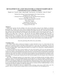
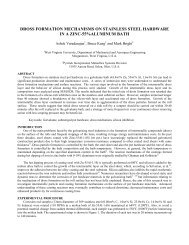
gRAPHiTE RELEASE AgEnTS<br />
<strong>Pyrotek</strong> offers three different<br />
Nekote products to prevent the<br />
alum<strong>in</strong>ium sheet from stick<strong>in</strong>g<br />
to the roll shell. All three products are<br />
exceptionally well dispersed with ultra<br />
f<strong>in</strong>e graphite particles suspended <strong>in</strong> water.<br />
Figure 13 shows the typical technical data<br />
for the three types of Nekote products.<br />
<strong>Pyrotek</strong> has a recommended dilution<br />
ratio of 1 part Nekote to 220 parts water.<br />
The concentration of graphite depends on<br />
many different factors of caster operation.<br />
If stick<strong>in</strong>g occurs us<strong>in</strong>g the recommended<br />
ratio, the operator should first try open<strong>in</strong>g<br />
the spray nozzles before decreas<strong>in</strong>g the<br />
dilution ratio.<br />
It is important to vigorously shake the<br />
conta<strong>in</strong>er of concentrate prior to mix<strong>in</strong>g<br />
it with water. It is recommended to beg<strong>in</strong><br />
Figure 13 - Typical properties of nekote products<br />
the mixer or agitator <strong>in</strong> the tank of water<br />
and slowly pour<strong>in</strong>g the concentrated<br />
Nekote <strong>in</strong>to the vortex of the mixer to<br />
ga<strong>in</strong> a good dispersion. The mix<strong>in</strong>g tank<br />
and delivery tank should be agitated at<br />
all times dur<strong>in</strong>g use. Due to the<br />
casthouse environment, it is<br />
important to keep the diluted<br />
tanks covered to prevent debris<br />
from enter<strong>in</strong>g the tank, which could clog<br />
the spray nozzles.<br />
N e k o t e - 3 5 T<br />
concentrate may<br />
become thixotropic<br />
over a period of<br />
time. A thixotropic<br />
solution holds the<br />
solid particles <strong>in</strong> a<br />
gel form to prevent<br />
settl<strong>in</strong>g. The operator<br />
should shake the jug<br />
to release the gel<br />
and the product will<br />
return to the orig<strong>in</strong>al<br />
liquid and pourable<br />
form.<br />
Figure 12 - nekote-35<br />
Nekote-35XL is the newest generation of<br />
graphite release agents because the graphite<br />
particles stay <strong>in</strong> suspension much longer<br />
than Nekote-35 and without becom<strong>in</strong>g<br />
thixotropic like Nekote-35T.<br />
TECHniCAL ASSiSTAnCE <strong>in</strong><br />
ConT<strong>in</strong>uouS SHEET CAST<strong>in</strong>g<br />
<strong>Pyrotek</strong> has well tra<strong>in</strong>ed sales eng<strong>in</strong>eers<br />
world-wide <strong>in</strong> cont<strong>in</strong>uous sheet cast<strong>in</strong>g.<br />
nekote-35 nekote-35xL nekote-35T iSo Procedure<br />
Solids, wt% 22.0 ± 0.5 22.0 ± 0.5 24.0 ± 0.5 CW 8224<br />
pH 9.5 ± 0.5 9.5 ± 0.5 9.5 ± 0.5 CW 8216<br />
Viscosity, cPs1 25 75 200 CW 8220<br />
Particle Size, Median2 ,µm 1.40 ± 0.25 1.40 ± 0.15 1.40 ± 0.15 CW 8226<br />
Particle Size, Max2 , µm 15 10 10 CW 8226<br />
1 Brookfield Model LVT II - Average calculated on batches prepared s<strong>in</strong>ce 2004<br />
Viscosity measured on samples that brought directly from production then stored for one hour at 77ºF<br />
#2 Sp<strong>in</strong>dle at 60 RPM at 77°F<br />
2 Horiba LA 500 Particle Size Analyzer<br />
<strong>Pyrotek</strong> also has designated product<br />
specialists <strong>in</strong> all areas of sheet cast<strong>in</strong>g, as<br />
well as a professional technical services<br />
consult<strong>in</strong>g team. On-site technical assistance<br />
is available for casthouse operations.<br />
pyrotek<br />
supplement<br />
NEKOTE TM<br />
RELEASE AGENTS<br />
PYRoTEK’S<br />
MiSSion<br />
“Provid<strong>in</strong>g<br />
<strong>in</strong>novative<br />
solutions<br />
to customer<br />
needs<br />
utiliz<strong>in</strong>g<br />
our global<br />
resources.”<br />
Page 9
<strong>Improv<strong>in</strong>g</strong> <strong>Performance</strong> - Cont<strong>in</strong>uous Cast<strong>in</strong>g<br />
<strong>Pyrotek</strong><br />
has well<br />
tra<strong>in</strong>ed sales<br />
eng<strong>in</strong>eers <strong>in</strong><br />
cont<strong>in</strong>uous<br />
sheet<br />
cast<strong>in</strong>g <strong>in</strong><br />
world-wide<br />
locations<br />
as well as<br />
designated<br />
product<br />
specialists.<br />
Burtay Çalli,<br />
European Cont<strong>in</strong>uous<br />
Cast<strong>in</strong>g Consultant<br />
Page 10<br />
ConCLuSion<br />
Cont<strong>in</strong>uous sheet cast<strong>in</strong>g is a grow<strong>in</strong>g<br />
and important segment of the alum<strong>in</strong>ium<br />
<strong>in</strong>dustry. Metal quality is dictated by the<br />
end product. Excellent th<strong>in</strong> gauge foil<br />
quality is achievable by us<strong>in</strong>g the correct<br />
products and equipment and by follow<strong>in</strong>g<br />
predeterm<strong>in</strong>ed production procedures.<br />
<strong>Pyrotek</strong> is aware of the growth <strong>in</strong> cont<strong>in</strong>uous<br />
sheet cast<strong>in</strong>g and is respond<strong>in</strong>g to the<br />
needs of this <strong>in</strong>dustry segment. Innovative<br />
and improved products and materials<br />
have been developed, while other new<br />
potential materials are be<strong>in</strong>g tested by<br />
the <strong>Pyrotek</strong> Research and Development<br />
pyrotek<br />
supplement<br />
group. Unique new equipment has been<br />
designed and developed for the specific<br />
needs for cont<strong>in</strong>uous sheet cast<strong>in</strong>g.<br />
Cont<strong>in</strong>uous sheet cast<strong>in</strong>g<br />
is a grow<strong>in</strong>g and important<br />
segment of the alum<strong>in</strong>ium<br />
<strong>in</strong>dustry.<br />
These new developments evolve not<br />
only from <strong>Pyrotek</strong>’s R&D group, but from<br />
partnerships with customers - provid<strong>in</strong>g<br />
<strong>in</strong>novative solutions and cont<strong>in</strong>uously<br />
improv<strong>in</strong>g materials, products, equipment<br />
and global expertise.
<strong>Improv<strong>in</strong>g</strong> <strong>Performance</strong> - Cont<strong>in</strong>uous Cast<strong>in</strong>g<br />
PYRoTEK’S MAJoR LoCATionS<br />
ASiA<br />
CHINA, Shenzhen<br />
Phone: (86) 755-26632324<br />
e-mail: shenzhen@pyrotek.<strong>in</strong>fo<br />
INDIA, Pune<br />
Phone: (91) 21-375-6800<br />
e-mail: pune@pyrotek.<strong>in</strong>fo<br />
INDONESIA, Jakarta<br />
Phone: (62) 21-563-8507<br />
e-mail: jakarta@pyrotek.<strong>in</strong>fo<br />
JAPAN, Kobe<br />
Phone: (81) (0)78-265-5590<br />
e-mail: kobe@pyrotek.<strong>in</strong>fo<br />
KOREA, Daegu<br />
Phone: 82 (0)53-523-5202<br />
e-mail: korea@pyrotek.<strong>in</strong>fo<br />
MALAYSIA, Kuala-Lumpur<br />
Phone: (603) 5631-3096<br />
e-mail: kualalumpur@pyrotek.<strong>in</strong>fo<br />
TAIWAN, Kaohsiung City<br />
Phone: (886) 7-224-8222<br />
e-mail: taiwan@pyrotek.<strong>in</strong>fo<br />
THAILAND, Bangkok<br />
Phone: (66) (0) 2 361-4870<br />
e-mail: bangkok@pyrotek.<strong>in</strong>fo<br />
AuSTRALiA<br />
AUSTRALIA (ANZ HEADQUARTERS)<br />
Phone: (61) (0)2 9631-1333<br />
e-mail: sydney@pyrotek.<strong>in</strong>fo<br />
CAnADA<br />
QUEBEC, Drummondville<br />
Phone: (819) 477-0734<br />
e-mail: drummondville@pyrotek.<strong>in</strong>fo<br />
EuRoPE<br />
CZECH REPUBLIC, Blansko<br />
Phone: (420) (0) 516-527-111<br />
e-mail: blansko@pyrotek.<strong>in</strong>fo<br />
GERMANY, Grevenbroich<br />
Phone: (49) (0)2182-8-10-20<br />
e-mail: grevenbroich@pyrotek.<strong>in</strong>fo<br />
SWEDEN, Ed<br />
Phone: (46) (0) 534-62000<br />
e-mail: ed@pyrotek.<strong>in</strong>fo<br />
SWITZERLAND, Sierre<br />
Phone: (41) (0)27-455-82-64<br />
e-mail: sierre@pyrotek.<strong>in</strong>fo<br />
UNITED KINGDOM, Milton<br />
Keynes<br />
Phone: (44) (0)1 908-561155<br />
e-mail: miltonkeynes@pyrotek.<strong>in</strong>fo<br />
MExiCo<br />
MEXICO, Santa Catar<strong>in</strong>a<br />
Phone: (52) 81-8336-9117<br />
e-mail: mexico@pyrotek.<strong>in</strong>fo<br />
MiDDLE EAST<br />
UNITED ARAB EMIRATES, Dubai<br />
Phone: (971) (0)4-883-77-00<br />
e-mail: dubai@pyrotek.<strong>in</strong>fo<br />
nEW ZEALAnD<br />
NEW ZEALAND, Auckland<br />
Phone: (64) (0)9 272-2056<br />
e-mail: auckland@pyrotek.<strong>in</strong>fo<br />
RuSSiA/CiS<br />
RUSSIA/CIS, Moscow<br />
Phone: (7) 095-230-71-63<br />
e-mail: moscow@pyrotek.<strong>in</strong>fo<br />
SouTH AFRiCA<br />
REPUBLIC OF SOUTH AFRICA,<br />
Richards Bay<br />
Phone: (27) (0)35 7974039<br />
e-mail: richardsbay@pyrotek.<strong>in</strong>fo<br />
This supplement can also be viewed at www.pyrotek.<strong>in</strong>fo/cont<strong>in</strong>uous_cast<strong>in</strong>g<br />
Read other supplements <strong>in</strong> this series:<br />
SouTH AMERiCA<br />
BRASIL, São Paulo<br />
Phone: (55) (0)11-4786-5233<br />
e-mail: saopaulo@pyrotek.<strong>in</strong>fo<br />
VENEZUELA, Puerto Ordaz<br />
Phone: (58) 286-994 1894<br />
e-mail: puertoordaz@pyrotek.<strong>in</strong>fo<br />
u.S.A.<br />
CALIFORNIA, Cerritos<br />
Phone: (562) 623-0085<br />
e-mail: cerritos@pyrotek.<strong>in</strong>fo<br />
INDIANA, Columbia City<br />
Phone: (260) 248-4141<br />
e-mail: columbiacity@pyrotek.<strong>in</strong>fo<br />
INDIANA, Evansville<br />
Phone: (812) 867-6343<br />
e-mail: evansville@pyrotek.<strong>in</strong>fo<br />
NEW YORK, Canastota<br />
Phone: (315) 697-8410<br />
e-mail: canastota@pyrotek.<strong>in</strong>fo<br />
NEW YORK, Elmsford<br />
Phone: (914) 345-4740<br />
e-mail: elmsford@pyrotek.<strong>in</strong>fo<br />
NORTH CAROLINA, Salisbury<br />
Phone: (704) 642-1993<br />
e-mail: salisbury@pyrotek.<strong>in</strong>fo<br />
OHIO, Solon<br />
Phone: (440) 349-8800<br />
e-mail: solon@pyrotek.<strong>in</strong>fo<br />
PENNSYLVANIA, Carlisle<br />
Phone: (717) 249-2075<br />
e-mail: carlisle@pyrotek.<strong>in</strong>fo<br />
WASHINGTON, Spokane Valley<br />
Phone: (509) 926-6211<br />
e-mail: spokane@pyrotek.<strong>in</strong>fo<br />
WISCONSIN, Waukesha<br />
Phone: (262) 524-9095<br />
e-mail: waukesha@pyrotek.<strong>in</strong>fo<br />
Explore the many filtration solutions to improve your melt quality at www.pyrotek.<strong>in</strong>fo/filtration<br />
Learn more about improv<strong>in</strong>g performance <strong>in</strong> your furnace operations at www.pyrotek.<strong>in</strong>fo/furnace_operations<br />
Improve your furnace melt treatment process with <strong>in</strong>formation at www.pyrotek.<strong>in</strong>fo/melt_treatment<br />
F<strong>in</strong>d out about solutions for the degass<strong>in</strong>g process at www.pyrotek.<strong>in</strong>fo/degass<strong>in</strong>g<br />
Investigate how to improve your slab cast<strong>in</strong>g processes at www.pyrotek.<strong>in</strong>fo/slab_cast<strong>in</strong>g<br />
pyrotek<br />
supplement<br />
<strong>Pyrotek</strong> is<br />
unique <strong>in</strong><br />
its ability to<br />
provide the<br />
<strong>in</strong>tegration<br />
of <strong>in</strong>novative<br />
technologies,<br />
process<br />
expertise<br />
and a global<br />
perspective.<br />
CORPORATE<br />
OFFICE<br />
9503 East Montgomery Avenue<br />
Spokane Valley, WA 99206<br />
Phone: (509) 926-6212<br />
Fax: (509) 927-2408<br />
e-mail: <strong>in</strong>fo@pyrotek.<strong>in</strong>fo<br />
Visit<br />
<strong>Pyrotek</strong><br />
onl<strong>in</strong>e<br />
at<br />
www.pyrotek.<strong>in</strong>fo<br />
Page 11
<strong>Improv<strong>in</strong>g</strong> <strong>Performance</strong> - Cont<strong>in</strong>uous Cast<strong>in</strong>g<br />
pyrotek<br />
supplement