INSTRUCTIONS MANUAL FOR - Pres-Vac Engineering Aps
INSTRUCTIONS MANUAL FOR - Pres-Vac Engineering Aps
INSTRUCTIONS MANUAL FOR - Pres-Vac Engineering Aps

You also want an ePaper? Increase the reach of your titles
YUMPU automatically turns print PDFs into web optimized ePapers that Google loves.
OWNER:<br />
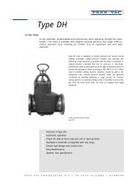
INSTRUCTION <strong>MANUAL</strong> <strong>FOR</strong><br />
TYPE 2389<br />
SYSTEM DESCRIPTION<br />
AND OPERATING/MAINTENANCE<br />
<strong>INSTRUCTIONS</strong> <strong>FOR</strong><br />
HS-ISO-VAC<br />
VACUUM VALVE<br />
REV. 2<br />
CUSTOMER IN<strong>FOR</strong>MATION<br />
HULL NO.:<br />
PRES-VAC REF. NO.:<br />
PRES-VAC ENGINEERING A/S PHONE: +45 4817 4055<br />
SVANEVANG 3-5 TELEFAX: +45 4817 1788<br />
DK-3450 ALLERØD E-mail: presvac@pres-vac.com<br />
DENMARK
INSTRUCTION <strong>MANUAL</strong><br />
CONTENTS<br />
HS-ISO VACUUM VALVE<br />
Page 2 of 21<br />
Rev. 2 April 15, 2003<br />
1. Functional System Description ....................................................................................... 3<br />
1.1. General ................................................................................................................... 3<br />
1.1.1 Ordering Information ................................................................................................ 3<br />
1.2. Design .................................................................................................................... 3<br />
1.2.1 Product Suitability .................................................................................................... 3<br />
1.3. Function .................................................................................................................. 3<br />
1.3.1 Inspection ............................................................................................................... 4<br />
1.4. Capacity .................................................................................................................. 4<br />
2. Operating Instructions ................................................................................................... 4<br />
2.1. Installation .............................................................................................................. 4<br />
2.1.1 Service restrictions ................................................................................................... 4<br />
2.2. Operation ................................................................................................................ 4<br />
2.2.1. Drainage ................................................................................................................. 5<br />
2.2.2. Deposit indicator ..................................................................................................... 5<br />
2.2.3. Damaged Seals ....................................................................................................... 6<br />
2.2.4. Flushing Port ............................................................................................................ 6<br />
2.2.5. Optional Features ..................................................................................................... 7<br />
3. Maintenance Instructions ............................................................................................... 8<br />
3.1. General ................................................................................................................... 8<br />
3.1.1. Inspection ............................................................................................................... 8<br />
3.2. Corrosion Protection.................................................................................................. 8<br />
3.2.1. Coating Repair ......................................................................................................... 8<br />
3.3. Safety Regulations For Maintenance Work ................................................................... 8<br />
3.4. Onboard Verifying Of Set-<strong>Pres</strong>sure .............................................................................. 9<br />
3.5. Directions For Disassembly / Assembly And Cleaning ................................................... 10<br />
4. Spares ........................................................................................................................... 12<br />
DRAWING NO. 2389-1 (Spare Part Ordering List) ................................................................ 13<br />
5. Trouble-Shooting .......................................................................................................... 14<br />
6. Laboratory Report, Summary ........................................................................................ 17<br />
Enclosures:<br />
(1) Flow Charts<br />
(2) Product Review Document<br />
(2) Certificates<br />
(3) Workshop Test Certificate<br />
(4) Maintenance Log Sheet<br />
Page
INSTRUCTION <strong>MANUAL</strong><br />
HS-ISO VACUUM VALVE<br />
1. Functional System Description<br />
1.1. General<br />
Page 3 of 21<br />
Rev. 2 April 15, 2003<br />
The purpose of this vacuum valve is to provide automatic control of pressure conditions during<br />
discharging, voyage, and de-ballasting without any manual operation. Additionally, the vacuum valve<br />
protects the tank against excessive vacuum, when the gas return line is connected to the shore facility<br />
and when loading is carried out with forced suction of vapour to the shore 1) , in accordance with the<br />
VECS-requirements. Furthermore, this vacuum valve provides active protection against fire and<br />
explosions on deck, in terms of preventing a passage of flame into the protected tank.<br />
1.1.1. Ordering Information<br />
Ordering information according to ISO 15364 should be provided by the customer, if not, it is the<br />
customers responsibility that service restrictions, tank pressure limitations, etc. are adhered to.<br />
1.2. Design<br />
The vacuum valve consists of a valve housing with a movable vacuum disc and stem. Correct function of<br />
the valve is tested by check-lifting the movable parts by means of pressing the check-lift handle (or<br />
button on some versions) beneath the vacuum unit from its lower position to its upper position. The<br />
check-lift is designed to be self-closing.<br />
1.4. Capacity<br />
WARNING! The attending crew must be familiar with the normal friction in the system in<br />
This valve is specifically designed with a view to address in-service maintenance, allow inspection of all<br />
vital parts from the outside without use of tools, and allow wear parts to be replaced in-situ. Essential<br />
functions are reflected by indicators, which are clearly visible from the outside at all times. The system<br />
has the simplicity of a weight-loaded design, while adding the in-service advantages of large net<br />
clearances through gas passage-ways to minimize clogging due to fouling from residue/condensate.<br />
1.2.1. Product Suitability<br />
Besides from complying with ISO 15364, a valve design has to be elaborated on in a Product Review<br />
Document, a product drawing and a manual. The ISO standard does not provide any measures against<br />
which a design can be constructed and considered as being “in conformity”. The standard merely<br />
provides general guidelines and, in particular, recommendations for maintenance. It is exclusively the<br />
owner´s/user´s responsibility to ensure that the valve is adequate for the actual installation and the<br />
usage intended. The owner/user shall do this on basis of:<br />
- A product Review Document describing the valve on basis of ISO 15364.<br />
- A product drawing<br />
- IMO MSC/Circ. 677/1009 certification<br />
- Certified service instructions<br />
- This manual<br />
It is the owner´s and or user´s responsibility to review and establish that the selected valve is correctly<br />
sized according to USCG (VECS) rules and IMO MSC/Circ. 731, and made in a design that will match the<br />
available efforts for maintenance. Various types of valves with different maintenance requirements are<br />
available in the PRES-VAC range with escalating prices for less maintenance requiring types.<br />
1.3. Function<br />
order to valuate when cleaning is required. Being able to activate the check-lift<br />
itself by applying great force does not mean that the moveable parts are freely<br />
moving.<br />
<strong>Vac</strong>uum build-up in the cargo tank forces the vacuum disc from its seat (opening pressure). When the<br />
tank vacuum again drops to the valve´s preset level, the disc will re-seat. For details of the performance<br />
characteristics, please refer to the certified flow charts as enclosed.<br />
1) Some applications are subject to requirements stating that the capacity shall also cover the loading rate + vapour growth rate.<br />
Confer with the flow chart as this is not always the case.
INSTRUCTION <strong>MANUAL</strong><br />
1.3.1. Inspection<br />
HS-ISO VACUUM VALVE<br />
Page 4 of 21<br />
Rev. 2 April 15, 2003<br />
Due to the relatively large net clearance through the valve, the inner parts are much less sensitive to<br />
deposits than ordinary designs. If no thick deposits are detected by means of the fouling indicator pins<br />
and by visual inspection after removal of the seat-beds in case of any doubts, the valve is in working<br />
condition and no further precautions are necessary. The allowable thickness of deposits before further<br />
inspection and, as appropriate, cleaning is necessary at a total diameter of the fouling pin of 12 mm. This<br />
measure, however, is only indicative and does not substitute visual inspection after removal of the seat-<br />
bed. See section 2.2.2.<br />
1.4. Capacity<br />
The valve's capacity is rated in standard air. For conversion to maximum loading rates for different<br />
cargoes, please refer to the MASTER'S LOADING CHART as per latest revision of IMO MSC/CIRC. 731.<br />
Other considerations are required for gas collection systems where the vacuum capacity shall equal the<br />
possible suction rate from shore. Please contact <strong>Pres</strong>-<strong>Vac</strong> <strong>Engineering</strong> for further guidance on this<br />
subject.<br />
2. Operating Instructions<br />
CAUTION! Transport, storage and handling of the valve shall take place in upright position.<br />
2.1. Installation<br />
Remove all packing material.<br />
Normally, the vacuum valve and pressure valve are delivered as one unit. For further information, refer<br />
to Instructions Manual for HS-ISO <strong>Pres</strong>sure Valve, section 2.<br />
If this is not the case, installation is accomplished by bolting the valve flange to the tank vent pipe's<br />
mating flange with a suitable gasket between. Check-lift to verify unobstructed movement of disc. Follow<br />
IMO MSC/Circ. 731 pressure drop calculation during system check to verify correct function.<br />
2.1.1 Service Restrictions<br />
See CE certificate for:<br />
1. Minimum MESG of cargo vapour.<br />
2. Minimum vacuum relief setting.<br />
3. Maximum fouling level: See this manual.<br />
4. Maintenance procedures must be observed for proper function of the equipment.<br />
2.2. Operation<br />
Before loading, discharging, and de-ballasting the valve must be check-lifted to ascertain free movability<br />
of the vacuum disc. Correct check-lifting is accomplished by pulling the check-lift handle (or pushing the<br />
button, if no check-lift handle) from its lower position (fig.1) to its upper position (fig. 2) and back again.<br />
The check-lift is self-closing when in proper maintained condition. If not, it should be cleaned and the rest<br />
of the valve inspected/cleaned.<br />
1.4. WARNING! Capacity The attending crew must be familiar with the normal friction in the system in<br />
The valve's capacity order is to rated valuate in standard when air. cleaning For conversion is required. to maximum Being able loading to activate rates for the different check-lift cargoes,<br />
please refer to itself the MASTER'S by applying LOADING great force CHART does as not per mean latest that revision the of moveable IMO MSC/CIRC. parts are 731. freely Other<br />
considerations are required for gas collection systems where the vacuum capacity shall equal the possible<br />
moving.
INSTRUCTION <strong>MANUAL</strong><br />
HS-ISO VACUUM VALVE<br />
Fig. 1. Check-Lift closed Fig. 2. Check-Lift open<br />
Page 5 of 21<br />
Rev. 2 April 15, 2003<br />
During normal voyage, the vacuum valve type ISO operates automatically and equalizes vacuum caused<br />
by thermal variations.<br />
WARNING! As per SOLAS-requirements, check-lifting must be carried out before loading,<br />
2.2.1. Drainage<br />
The valve is self-draining due to large net clearances and no horizontal surfaces on the inside of the<br />
valve.<br />
2.2.2. Deposit Indicator<br />
discharging or ballasting is commenced. If the valve does not move freely,<br />
the cause should be determined and corrected immediately.<br />
To examine for build-up of residue in the valve, unscrew the Plug with deposit indicator (pos. 23 on fig.<br />
16, page 10) and check it for residue thickness. If the residue thickness is over 1 mm. (= pin diameter<br />
over 12mm), cleaning of the interior of the valve is necessary. The cleaning method depends on the<br />
cargo type, but basically paragraph 3.5 should be followed. For certain crystallizing cargoes, heating<br />
arrangement may be necessary according to the chemical code.
INSTRUCTION <strong>MANUAL</strong><br />
2.2.3. Damaged seals.<br />
HS-ISO VACUUM VALVE<br />
Page 6 of 21<br />
Rev. 2 April 15, 2003<br />
It is of outmost importance that the seals are kept in a good condition and are changed before<br />
reassembly, as necessary, to maintain leakage-free operation.<br />
Consequences of damaged or missing seals are as follows:<br />
Type of seal Damaged seal Missing seal<br />
O-rings in flange connections Small leak of cargo or inert gas. Leak of cargo or inert gas.<br />
Small salt water ingress in tank<br />
O-rings in Disc unit Small leak of cargo or inert gas. Leak of cargo or inert gas.<br />
Small salt water ingress in tank<br />
Gasket for Plug w. deposit indicator Leak of cargo or inert gas. Leak of cargo or inert gas.<br />
2.2.4. Flushing Port<br />
Small salt water ingress in tank.<br />
When loading a new cargo, for which cleaning of the HS-ISO <strong>Vac</strong>uum Valve and vent pipe is required,<br />
this procedure is to be followed:<br />
1) Unscrew the flushing plug (pos. 23) on fig. 16 (only when the tank is depressurized).<br />
2) Connect the hose with the cleaning fluid to the flushing port.<br />
3) Start cleaning.<br />
4) Remove the hose and mount the flushing plug.<br />
Fig. 3. Flushing of HS-ISO vacuum Valve<br />
WARNING !<br />
The flushing system may only<br />
be used when it is otherwise<br />
safe to clean the piping.
INSTRUCTION <strong>MANUAL</strong><br />
2.2.5. Optional Features<br />
HS-ISO VACUUM VALVE<br />
Optional accessories for special requirements are available.<br />
Page 7 of 21<br />
Rev. 2 April 15, 2003<br />
Fig. 5: Proximity switch for Fig. 6: Fixture for forced Fig. 7: Zero emission kit<br />
stand-by valves closing for PO service for special cargo<br />
Fig. 8: Heating Arrangement Fig. 9: Side mounted Fig. 10: Dual nozzle for im-<br />
(other versions are Gas Freing Cover proved gas disper-<br />
available depending sion of small volume<br />
on size)<br />
Fig. 11: Self closing valve Fig. 12: Gas freeing Cover Fig. 13: Dessicator to prevent<br />
to prevent cargo damage to hygroscopic<br />
escape from sun- cargo<br />
ken vessel
INSTRUCTION <strong>MANUAL</strong><br />
3. Maintenance Instructions<br />
3.1. General<br />
HS-ISO VACUUM VALVE<br />
Page 8 of 21<br />
Rev. 2 April 15, 2003<br />
As per SOLAS-requirements, the following service intervals shall be followed as a minimum:<br />
A.<br />
After 6 months of operation, the valve shall be inspected for proper function and, if necessary, be<br />
cleaned. However, we recommend that the valve be inspected more often depending on the cargo type.<br />
If the check-lift handle does not operate freely, cleaning is required.<br />
B.<br />
After further 6 months of operation, the valve shall be taken apart and cleaned.<br />
Dismounting the valve house, see fig. 16 on page 10, provides access to do the necessary cleaning, i.e.,<br />
pull of the seat bed and all parts are accessible.<br />
3.1.1 Inspection<br />
Due to the relatively large net clearance through the valve, the inner parts are much less sensitive to<br />
deposits than ordinary designs. If no thick deposits are detected by means of the fouling indicator pins<br />
and by visual inspection after removal of the seat-beds in case of any doubts, the valve is in working<br />
condition and no further precautions are necessary.<br />
3.2. Corrosion Protection<br />
When repairing the coating follow the instructions from the producer of the coating quality referred to in<br />
the vessel´s general manual.<br />
3.2.1. Coating Repair<br />
Due to the large inner clearance the valve will not block because of surface corrosion, and repairing of<br />
the coating is therefore not necessary from a valve functional aspect, only if the cargo vapor is damaging<br />
to the main body parts.<br />
3.3. Safety Regulations For Maintenance Work<br />
Spark free tools should be used if maintenance work is carried out while the valve is mounted on the<br />
cargo tank.<br />
WARNING! All maintenance work must be carried out with necessary precautions in<br />
regard to the cargo’s flammability and toxicity.<br />
NOTE! Before dismounting the seat bed and replacing with a new one – the tank pressure<br />
should be lowered to the same level as when performing ullage measurement<br />
through an open deck valve.
INSTRUCTION <strong>MANUAL</strong><br />
HS-ISO VACUUM VALVE<br />
3.4. Onboard Verifying Of the Set-<strong>Pres</strong>sure<br />
Page 9 of 21<br />
Rev. 2 April 15, 2003<br />
After overhaul, verifying of the set-pressure is recommended. This can be accomplished by either<br />
removing the top cover and controlling the pull-weight of the vacuum disc with a PRES-VAC<br />
Dynamometer and confer with PRES-VAC or use the PRES-VAC Test Rig, type TR or TRM, see fig. 14 and<br />
15 below.<br />
The actual valve set-pressure is stamped on the valve body.<br />
The Test Rig, type TR or TRM, is used for onboard verifying of the set-pressure as well as measurement<br />
of the leakage rate to ensure compliance with environmental regulations.<br />
For further details on type TR or TRM and Dynamometer, please refer to a separate manual. This<br />
equipment can be purchased from PRES-VAC.<br />
Fig. 14: Test Rig Fig.15: Dynamometer<br />
(Mechanical and Ex versions are also available)
INSTRUCTION <strong>MANUAL</strong><br />
HS-ISO VACUUM VALVE<br />
Page 10 of 21<br />
Rev. 2 April 15, 2003<br />
3.5. Directions For Disassembly / Assembly And Cleaning<br />
Normal cleaning and inspection, see fig. 16:<br />
1. Remove the Interior of the <strong>Vac</strong> unit by unscrewing the bolts (pos. 32) and washers (pos. 33).<br />
Disassembly of the filter unit:<br />
2. Remove the Screws (pos. 34) and Washers (pos. 35).<br />
3. Tilt the filter element assembly slightly and pull it from the Flange (pos. 2).<br />
4 Remove the check-lift assembly by unscrewing the Nuts (pos. 13).<br />
5. Push carefully the filter element out (pos. 7).<br />
6. Inspect and clean all parts. Repair or replace damaged parts as appropriate.<br />
CAUTION! Apply an even pressure on the whole surface of the filter element to avoid<br />
damage.<br />
Fig. 16: Assembly Drawing for Inspection and Cleaning of HS-ISO <strong>Vac</strong>uum Valve.
INSTRUCTION <strong>MANUAL</strong><br />
HS-ISO VACUUM VALVE<br />
Assembly after normal cleaning and inspection<br />
1. Assembly is done in the opposite sequence.<br />
Replacement of vacuum seat (pos. 5 on fig. 16)<br />
Page 11 of 21<br />
Rev. 2 April 15, 2003<br />
NOTE! For cleaning we recommend a thin lubrication oil and a brush. If damage on any<br />
1. Unscrew bolts (pos. 32) and remove washers (pos. 33)<br />
2. Pull out the filter unit including the O-ring (pos. 27)<br />
3. Remove the vacuum disc (pos. 4) together with stem (pos. 9), washer (pos. 26) , lock washers<br />
(pos. 11) and nut (pos. 10).<br />
4. Unscrew the seat by means of a key between the ribs.<br />
5. Clean thread and insert new seat after surface lapping.<br />
Assembly<br />
1. Assembly is done in the opposite sequence.<br />
NOTE: Seat-beds can be re-used from PRES-VAC at cost of lapping and re-coating, as necessary.<br />
General<br />
parts is observed, repair or replacement must take place.<br />
CAUTION! Pay attention to filter element during paint work on deck.<br />
Screws and bolts not protected from loosening, should be secured by a suitable adhesive, such as PRES-<br />
VAC part no.: 1323-8.<br />
RECOMMENDATION<br />
Fill in the maintenance log sheet in connection with inspection and service.
INSTRUCTION <strong>MANUAL</strong><br />
4. Spares<br />
HS-ISO VACUUM VALVE<br />
Page 12 of 21<br />
Rev. 2 April 15, 2003<br />
There are no class requirements for carrying spares on board. If spares are required, please use the<br />
following procedure:<br />
1. Take a copy of the inserted drawing no. 2389-1.<br />
2. Identify the components and write the required quantities on the part list.<br />
3. Advise builder of ship and new building number.<br />
4. Advise Vessel name.<br />
5. Advise serial number punched into the flange of the valve.<br />
Fax the drawing to our office in DENMARK.<br />
When we have the above information, our files contain all further details.<br />
When ordering spare parts, please call our office in DENMARK.<br />
Our telefax and E-mail are open 24 hours a day<br />
Telefax No. ....... +45 48 17 17 88<br />
E-mail .............. presvac@pres-vac.com<br />
Our telephone is open during normal office hours<br />
Telephone No.: . +45 48 17 40 55<br />
Our postal address:<br />
PRES-VAC ENGINEERING A/S<br />
Svanevang 3-5<br />
DK-3450 Allerød<br />
Denmark
INSTRUCTION <strong>MANUAL</strong><br />
SPARE PART ORDERING LIST<br />
HS-ISO VACUUM VALVE<br />
Page 13 of 21<br />
Rev. 2 April 15, 2003
INSTRUCTION <strong>MANUAL</strong><br />
5. Trouble-shooting<br />
HS-ISO VACUUM VALVE<br />
Problem Remedy<br />
Tank pressure is too high A.<br />
Tank vacuum is too high<br />
Page 14 of 21<br />
Rev. 2 April 15, 2003<br />
Check in vessel’s Master Loading Chart according to<br />
IMO MSC/Circ. 731 what the maximum permissible<br />
loading rate is and the corresponding loading rate<br />
with corrections for vapor density and vapor growth<br />
rate. Lower loading rate if necessary.<br />
B.<br />
Check that the valve is clean inside and take care of<br />
maintenance as per Section 3 if necessary.<br />
B.1.<br />
Check that the valve disc is able to travel full stroke<br />
by hand-lifting.<br />
B.2.<br />
Check that pressure seat/disc contact area (width)<br />
is not exceeding manufacturer’s recommendations<br />
to avoid a “aero-dynamic” lock (like blowing<br />
between two sheets of paper) as a consequence of<br />
“home-made” repairs.<br />
C.<br />
Check that the piping is unobstructed by cargo<br />
residue etc.<br />
D.<br />
Check that the pressure-tuning knob has not been<br />
tampered with by use of a calibrated test<br />
instrument.<br />
E.<br />
Contact PRES-VAC to check if the configuration of<br />
magnet-power and booster disc arrangement can<br />
be changed for a more suitable performance for the<br />
actual conditions of installation.<br />
A.<br />
Check in vessel’s Master Loading Chart according to<br />
IMO MSC/Circ. 731 what the maximum permissible<br />
discharge rate is. Check that pump is running with<br />
the intended delivery head to avoid unintended high<br />
rates. Lower pump rate if necessary.<br />
B.<br />
Check that the valve is clean inside and take care of<br />
maintenance as per Section 3 if necessary.<br />
B.1.<br />
Check that the valve disc is able to travel full stroke<br />
by hand-lifting.<br />
B.2.<br />
Check that vacuum seat/disc contact area (width) is<br />
not exceeding manufacturer’s recommendations to<br />
avoid a “aero-dynamic” lock (like blowing between<br />
two sheets of paper) as a consequence of “homemade”<br />
repairs.
INSTRUCTION <strong>MANUAL</strong><br />
HS-ISO VACUUM VALVE<br />
Tank vacuum is too high (continued) B.3.<br />
Not fully lifting pressure disc:<br />
The valve is leaking A.<br />
The valve is hammering A.<br />
Page 15 of 21<br />
Rev. 2 April 15, 2003<br />
Check that the vacuum disc’s contact area is dry to<br />
avoid a hydraulic lock.<br />
C.<br />
Check that the piping is unobstructed by cargo<br />
residue etc.<br />
D.<br />
Contact PRES-VAC.<br />
Due to the relative large venting capacity required<br />
according to USCG regulations on Vapor Emission<br />
Control Systems, which for some cargoes are nearly<br />
doubling the actual loading rate, valves may in fact<br />
be handling far less than designed for. Especially<br />
when the sizing procedure did not allow the VECS<br />
capacity to be present at an elevated tank pressure<br />
just below the maximum working pressure. In other<br />
words; a generous provision for venting capacity is<br />
a problem and the valve performance might appear<br />
as chattering or fluttering and can severely reduce<br />
the lifetime of seats and discs.<br />
The remedy available is to consult PRES-VAC for<br />
guidance on adjusting the opening setting and/or<br />
the configuration of the booster plate arrangement.<br />
In extreme cases, for instance for slop tanks<br />
equipped similar to the main cargo tanks, it may be<br />
necessary to install a dual, small capacity unit with<br />
a differing setting making the too large original<br />
valve a stand-by safety unit for the rare maloperating<br />
event.<br />
Clean valve discs and seats.<br />
B.<br />
Check pressure check-lift seal.<br />
C.<br />
Overhaul or replace seats and discs as appropriate.<br />
D.<br />
Contact PRES-VAC.<br />
Check that installation is within the service<br />
restrictions shown in the certification issued by the<br />
CE Notified Body ( <strong>FOR</strong>CE TECHNOLOGY). If not,<br />
contact PRES-VAC.<br />
B.<br />
If the valve is grossly over-sized for the actual<br />
capacity vented, the opening and closing cycle may<br />
reduce the expected lifetime of the sealing parts. If<br />
the differential between the capacity of the valve<br />
based on USCG VCS requirements is too far from<br />
the actual volume vented, the lifetime of the<br />
sealing parts is reduced.
INSTRUCTION <strong>MANUAL</strong><br />
The valve is hammering (continued)<br />
HS-ISO VACUUM VALVE<br />
C.<br />
Page 16 of 21<br />
Rev. 2 April 15, 2003<br />
Check Section 2.2.5 on “Valve Misbehaviour.”<br />
Hammering is by definition non-intended full stroke<br />
movement of the pressure disc and should not be<br />
misunderstood for non-fluttering.<br />
C.1.<br />
Hammering is not an issue with vacuum valves as<br />
these are modulating and therefore unstable in the<br />
opening phase. Since flash-back protection is not<br />
connected with a high velocity nozzle, disc<br />
movement is no concern, save from a lifetime<br />
aspect.<br />
D.<br />
Contact PRES-VAC to check if the configuration of<br />
magnet-power and booster disc arrangement can<br />
be changed for a more suitable performance for the<br />
actual conditions of installation.
LABORATORY REPORT - SUMMARY TESTED IN ACCORDANCE WITH MSC/Circ. 677/1009<br />
6. Laboratory Report, Summary<br />
SUBJECT: HS-ISO VACUUM VALVE<br />
The following report is part of the Instructions Manual as required by MSC/Circ. 677, paragraph 4.3 and<br />
should be kept on board the tanker.<br />
The report contains in a condensed form all conducted tests and results obtained, as well as all further<br />
information required, according to the IMO-rules, MSC/Circ. 677 as amended by Circ. 1009 and ISO<br />
15364.<br />
The complete Laboratory Report and test data including video documentation is on file with Force<br />
Technology, the CE Notified Body. The following tests were completed successfully as indicated on the<br />
attached certificates of Type Approval from Force Technology.<br />
Test<br />
1<br />
2<br />
3<br />
4<br />
5<br />
Description<br />
Corrosion test<br />
Hydraulic pressure<br />
test<br />
Flow test<br />
Flash-back test<br />
Ice test<br />
MSC/Circ.<br />
677/1009<br />
3.5.1<br />
3.5.2<br />
3.3.2<br />
3.2.2<br />
2.3.4<br />
Remarks:<br />
The corrosion tests were carried out on a test rig as<br />
shown on drawing no. 1194-26. The test results were<br />
to the satisfaction of the Notified body.<br />
The hydraulic tests were carried out on a test rig as<br />
shown on drawing no. 1194-317. The test results<br />
were to the satisfaction of the Notified body.<br />
The flow tests were carried out on a test rig as shown<br />
on drawing nos. 1194-148 and 1194-149. The results<br />
obtained appear from the inserted flow curves as<br />
enclosed.<br />
The flash-back tests were carried out on a test rig as<br />
shown on drawing no. 1194-160. In no case did<br />
flash-back occur.<br />
The ice test was carried out on a test rig as shown on<br />
drawing no. 1194-318. The test valve was cooled to<br />
–20 to –30 degrees Celsius. Hereafter the valve was<br />
check-lifted, and it was seen that the valve was fully<br />
operative.<br />
Additionally, separate flow testing has been performed in accordance with API 2000 Standard because<br />
flow testing as per MSC/Circ. 677/Circ. 1009 and ISO15364 does not automatically qualify for API 2000<br />
requirements since higher pressure and vacuum conditions are necessary for some valve configurations.<br />
Please refer to the attached Certificates of Type Approval from Force Technology.
LABORATORY REPORT - SUMMARY TESTED IN ACCORDANCE WITH MSC/Circ. 677/1009<br />
Drawing no.: 1194-26, Corrosion Test<br />
Drawing no.: 1194-317, Hydraulic <strong>Pres</strong>sure Test<br />
SUBJECT: HS-ISO VACUUM VALVE
LABORATORY REPORT - SUMMARY TESTED IN ACCORDANCE WITH MSC/Circ. 677/1009<br />
Drawing no.: 1194-149, Flow test<br />
Drawing no.: 1194-148, Flow Test<br />
SUBJECT: HS-ISO VACUUM VALVE
LABORATORY REPORT - SUMMARY TESTED IN ACCORDANCE WITH MSC/Circ. 677/1009<br />
Drawing no.: 1194-160, Flash-back Test<br />
Drawing no.: 1194-318, Ice Test<br />
SUBJECT: HS-ISO VACUUM VALVE