Huron & SNAP Documentation
Huron & SNAP Documentation Huron & SNAP Documentation
↓ To remove a FIR filter from the filter Program. ↓ To replace a loaded FIR filter Note: Each FIR filter in a Filter program utilises the number of DSP processors shown in the Filter Type box. The number of FIR filters which may be added to a program is limited by the number of DSP processors installed in the system. If the number of DSP processors required by the FIR filters exceeds those available, the system will return an error message and the excess filters will not be loaded. Inputs, Outputs, Mixing and Patching ↓ To mix the FIR filter outputs of a Filter program THE ENGINEERING TOOLS The filter selection window will disappear and the selected impulse response will appear as part of the Filter program (see Figure 56 below). Figure 56 — Filter program window with FIR filter added 1. Select the FIR filter. 2. On the Filter program window Click Delete. 1. Select the FIR filter to replace. 2. On the Filter program window Click Edit. 3. From the dialogue Select the replacement filter. 4. Click OK. Each FIR filter within a Filter program has one input channel and one output channel. It is possible to mix any number of outputs from these filters within the Convolver. Each time a FIR filter is added to a Filter program, the appropriate input and output patch points appear on the Convolver panel in the Patch Bay. When the outputs of the FIR filters are mixed they are combined to a single output point in the Patch Bay. 1. Select the FIR filter to be mixed from the Filter program window. 2. Click Channel. The following window will be displayed HURON TECHNICAL MANUAL PAGE 190
Currently selected patch point icon Note: It is only possible to mix downwards (in number) in the output list, thus it is possible to mix output 2 to output 1 but not output 1 to output 2 Input and Output Level Metering ↓ To display the input and output levels of a Filter program Figure 57 — Mixing Channels Fast Switching with Pre-loaded Filter Coefficients ↓ To fast switch between Filter programs THE ENGINEERING TOOLS 3. Change the current output channel by Clicking the patch point icon you wish to direct the output to. Patch points which are no longer used will disappear from the Patch Bay. 1. Select a Filter program from the Filter program window. 2. Click Meters. A level meter window will appear, each meter reflects the input and output levels of a single filter. The Convolver pre-loads Filter programs and their associated FIR filters into on board DRAM, as they are selected. When two or more Filter programs and their associated FIR filters fit into the available DRAM they can be “fast switched”. Fast switching allows two different Filter programs to be compared in close to real time. It is only possible to switch between Filter programs loaded into DRAM, the number of filters which can be loaded into DRAM simultaneously is denoted by the number of buffers available (in Table 1 — Filters available to the Convolver). A Filter program which has been pre-loaded is indicated by an asterisk (*) next to the Program Name in the Filter program list. 1. Click the first pre-loaded Filter program name. 2. Click the second pre-loaded Filter program name. HURON TECHNICAL MANUAL PAGE 191
- Page 141 and 142: Features Requirements The WavePlaye
- Page 143 and 144: Figure 49 — The WavePlayer-2 inte
- Page 145 and 146: ↓ Setting the RME Hammerfall as t
- Page 147 and 148: Note: The Waveplayer has now been s
- Page 149: Summary OTHER SIMULATION TOOLS •
- Page 152 and 153: Operation Starting ↓ To start the
- Page 154 and 155: ↓ To select a microphone setting
- Page 156 and 157: ↓ To specify the Echo settings
- Page 159 and 160: Integration under 32 bit Windows In
- Page 161 and 162: Positional Commands Note: The numbe
- Page 163 and 164: OTHER SIMULATION TOOLS SNAPGetRooms
- Page 165 and 166: MultiScape Commands Parameter Descr
- Page 167 and 168: Space Array Commands Parameter Desc
- Page 169 and 170: VMixer Commands Parameter Descripti
- Page 171 and 172: WavePlayer-2 Commands OTHER SIMULAT
- Page 173 and 174: OTHER SIMULATION TOOLS SNAPWP2Pause
- Page 175 and 176: OTHER SIMULATION TOOLS SNAPSetWaveH
- Page 177 and 178: Command Reference This section desc
- Page 179 and 180: WavePlayer Commands OTHER SIMULATIO
- Page 181: TCP/IP Commands OTHER SIMULATION TO
- Page 185 and 186: Introduction Features Overview of t
- Page 187 and 188: Operation Starting and Saving ↓ T
- Page 189: ↓ To add a FIR filter to the Filt
- Page 193 and 194: Introduction 96kHz Convolver Hardwa
- Page 195: Patching the 96kHz Convolver Loadin
- Page 198 and 199: Starting Note: If using measure to
- Page 200 and 201: Selecting the Output File ↓ To se
- Page 202 and 203: Signal Generation via MatLab Script
- Page 205 and 206: Introduction 96kHz Measurement Tool
- Page 207: Loading the 96kHz Measurement Tool
- Page 211 and 212: ; comments ( (dtype [bit16 | bit20
- Page 213 and 214: Introduction Operation Starting ↓
- Page 215 and 216: Dfilter Windows Interface ↓ To st
- Page 217 and 218: Lvec Windows Interface ↓ To start
- Page 219: Padvec Windows Interface ↓ To sta
- Page 223 and 224: Permute Windows Interface ↓ To st
- Page 225 and 226: Wingen Windows Interface ↓ To sta
- Page 227 and 228: SigGen Windows Interface ↓ To sta
- Page 229 and 230: ↓ To generate a piecewise linear
- Page 231 and 232: Vector Arithmetic Windows Interface
- Page 233 and 234: Introduction Features Operation ↓
- Page 235 and 236: Printing ↓ To print the SIM file
- Page 237 and 238: Altering the Axes ↓ To display sa
- Page 239: Summary THE ENGINEERING TOOLS • P
↓ To remove a FIR filter from the<br />
filter Program.<br />
↓ To replace a loaded FIR filter<br />
Note: Each FIR filter in a Filter<br />
program utilises the number of DSP<br />
processors shown in the Filter Type<br />
box. The number of FIR filters which<br />
may be added to a program is limited<br />
by the number of DSP processors<br />
installed in the system. If the number<br />
of DSP processors required by the FIR<br />
filters exceeds those available, the<br />
system will return an error message<br />
and the excess filters will not be<br />
loaded.<br />
Inputs, Outputs, Mixing and Patching<br />
↓ To mix the FIR filter outputs of<br />
a Filter program<br />
THE ENGINEERING TOOLS<br />
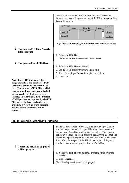
The filter selection window will disappear and the selected<br />
impulse response will appear as part of the Filter program (see<br />
Figure 56 below).<br />
Figure 56 — Filter program window with FIR filter added<br />
1. Select the FIR filter.<br />
2. On the Filter program window Click Delete.<br />
1. Select the FIR filter to replace.<br />
2. On the Filter program window Click Edit.<br />
3. From the dialogue Select the replacement filter.<br />
4. Click OK.<br />
Each FIR filter within a Filter program has one input channel<br />
and one output channel. It is possible to mix any number of<br />
outputs from these filters within the Convolver. Each time a<br />
FIR filter is added to a Filter program, the appropriate input and<br />
output patch points appear on the Convolver panel in the Patch<br />
Bay. When the outputs of the FIR filters are mixed they are<br />
combined to a single output point in the Patch Bay.<br />
1. Select the FIR filter to be mixed from the Filter program<br />
window.<br />
2. Click Channel.<br />
The following window will be displayed<br />
HURON TECHNICAL MANUAL PAGE 190


