Huron & SNAP Documentation
Huron & SNAP Documentation
Huron & SNAP Documentation

Create successful ePaper yourself
Turn your PDF publications into a flip-book with our unique Google optimized e-Paper software.
<strong>Huron</strong> Technical Manual<br />
Software version 3.2
Lake Technology <strong>Huron</strong> Technical Manual<br />
Software Version 3.2<br />
Revision 6.0<br />
HURON TECHNICAL MANUAL PAGE 3
Copyright © 1995-2003 Lake Technology Limited.<br />
First published 1995, as a Lake DSP publication.<br />
All rights reserved. No part of this publication may be<br />
reproduced or used in any form or by any means — graphic<br />
electronic, or mechanical including photocopying, recording,<br />
taping or information storage and retrieval systems — without<br />
written permission of the publisher.<br />
The enclosed materials are subject to pending and granted<br />
patent protection and to various patent, copyright and other<br />
intellectual property rights in various international jurisdictions.<br />
Manufactured: Sydney Australia. First printing 1995.<br />
Project editors: Stewart Bartlett 1995; Stephen Cox 1998; Roger<br />
Butler 1999-2002; Michael Potas 2002-2003.<br />
Section editors: Marcus Altman, Patrick Flanagan, Adam<br />
McKeag, Yarema Misko, Tony Place, Desmond So, Nick<br />
Mariette, Michael Potas.<br />
Page Layout/Design: Stephen Cox, Based on: “Microsoft®<br />
manual of style 1995 (Microsoft press)”, and “Xerox®<br />
publishing standards 1988 (Xerox press)”.<br />
InsideTrak is a registered trademark of the Polhemus<br />
Corporation. Lake Technology and all Lake products<br />
mentioned in this documentation are trademarks of Lake<br />
Technology Limited. Matlab is a registered trademark of<br />
Mathworks. Microsoft, Microsoft windows, MS, MS-DOS are<br />
registered trademarks of the Microsoft Corporation. Motorola<br />
is a registered trademark of the Motorola Corporation. Silicon<br />
Graphics is a registered trademark of Silicon Graphics<br />
Corporation.<br />
HURON TECHNICAL MANUAL PAGE 5
Disclaimer<br />
Copyright © 1995-2003 Lake Technology Limited.<br />
All rights reserved. Lake Technology Limited assumes no<br />
responsibility for any errors in this documentation. This<br />
information may supersede previously published specification<br />
of this product. Lake Technology Limited reserves the right to<br />
make changes to its products at any time without notice.<br />
Contact the Lake Technology Limited sales office in Sydney<br />
N.S.W. Australia for the latest product specification at the time<br />
of order.<br />
HURON TECHNICAL MANUAL PAGE 7
FCC Declaration (USA only) for<br />
<strong>Huron</strong> Workstation.<br />
Federal Communications Commission Radio Interference<br />
Statement Warning:<br />
This equipment has been tested and found to comply with the<br />
limits for a Class A digital device, pursuant to Part 15 of the<br />
FCC Rules. These limits are designed to provide reasonable<br />
protection against harmful interference in a commercial,<br />
industrial or business environment. This equipment generates,<br />
uses and can radiate radio frequency energy and, if not installed<br />
and used in accordance with the instructions, may cause<br />
harmful interference to radio communications. However, there<br />
is no guarantee that interference will not occur in a particular<br />
installation. If this equipment does cause harmful interference<br />
to radio reception, which can be determined by turning the<br />
equipment off and on, the user is encouraged to correct the<br />
interference by one or more of the following measures:<br />
Reorient or relocate the receiving antenna.<br />
Increase the separation between the equipment and the receiver.<br />
Connect the equipment to an outlet on a circuit different from<br />
that to which the receiver is connected.<br />
Consult the distributor or Lake Technology for help.<br />
Lake Technology Limited FCC Compliance Tests were<br />
conducted with FCC tested peripheral devices and shielded<br />
cables. Using equipment not FCC tested or making changes or<br />
modifications not expressly approved by Lake Technology<br />
Limited could void the users authority to operate the equipment.<br />
HURON TECHNICAL MANUAL PAGE 9
Warranty<br />
Lake Technology Limited A.C.N. 051 198 273 of Australia<br />
(“Lake”) warrants to the purchaser that the hardware and media<br />
embodying software in this product are free from defects in<br />
material and workmanship for a period of one (1) year from the<br />
date of purchase or shipment, whichever is earlier.<br />
If the purchaser discovers such a defect, they should notify<br />
Lake within the warranty period and return the product to Lake,<br />
indicating the defect and providing proof of purchase. Lake<br />
will examine the product and, if it finds that there is such a<br />
defect, will at its option either repair or replace the product,<br />
return the product to the purchaser within ninety (90) days of<br />
receipt and refund the purchaser’s shipping expenses. Shipping<br />
of products is at the purchaser’s sole risk.<br />
NOTE: — EXCLUSION AND LIMITATION OF LIABILITY<br />
TO THE FULL EXTENT PERMITTED BY APPLICABLE<br />
LAW, LAKE DISCLAIMS AND EXCLUDES ALL AND<br />
ANY WARRANTIES AND CONDITIONS IN RESPECT OF<br />
THIS PRODUCT. THIS EXCLUSION EXTENDS, WHERE<br />
LAWFUL TO DO SO, TO THE IMPLIED WARRANTIES OF<br />
MERCHANTABILITY AND FITNESS FOR A<br />
PARTICULAR PURPOSE. ALL SOFTWARE AND<br />
HARDWARE MAY HAVE ERRORS, AND THEREFORE<br />
THE USE OF THE LAKE SOFTWARE AND HARDWARE<br />
MUST BE BY SKILLED AND SUITABLY TRAINED<br />
PERSONNEL WHO CAN VERIFY THE RESULTS OF USE<br />
TO BE ACCURATE. LAKE THEREFORE SUPPLIES THE<br />
HARDWARE AND SOFTWARE SUPPLIED “AS IS”<br />
WITHOUT WARRANTY AS TO THE CORRECTNESS,<br />
COMPLETENESS OR ACCURACY OF THE RESULTS OF<br />
USE, OR AS TO ANY BENEFITS OF USE OF ANY<br />
NATURE. The limited warranty provided above is the only<br />
warranty made by Lake on this product. No oral or written<br />
information or advice given by Lake, its dealers, distributors,<br />
agents or employees will create a warranty or in any way<br />
increase the scope of this warranty, and you may not rely on<br />
any such information or advice.<br />
In no event will Lake be liable for any consequential, incidental<br />
or indirect damages (including damages for loss of business<br />
profits, business interruption, loss of business information)<br />
arising out of the use of or inability to use Lake products, even<br />
if Lake or an authorised Lake representative has been advised of<br />
the possibility of such damages or for any claim by any other<br />
party.<br />
HURON TECHNICAL MANUAL PAGE 11
Table of Contents<br />
DISCLAIMER......................................................................................................................................7<br />
FCC DECLARATION (USA ONLY) FOR HURON WORKSTATION.......................................9<br />
WARRANTY......................................................................................................................................11<br />
TABLE OF CONTENTS ..................................................................................................................13<br />
INTRODUCTION TO THE HURON .............................................................................................23<br />
AN OVERVIEW OF THE HURON DIGITAL AUDIO WORKSTATION ...............................25<br />
FEATURES .........................................................................................................................................26<br />
APPLICATIONS ..................................................................................................................................26<br />
THE HURON HARDWARE............................................................................................................27<br />
HURON HARDWARE COMPONENTS ...................................................................................................27<br />
STARTING THE HURON......................................................................................................................29<br />
INSTALLING NEW HARDWARE COMPONENTS ...................................................................................30<br />
INSTALLING AT ADD-IN CARDS .......................................................................................................31<br />
CONNECTING AUDIO INPUTS AND OUTPUTS TO THE HURON ......................................35<br />
ADDING ADDITIONAL I/O CARDS .....................................................................................................36<br />
THE HURON SOFTWARE COMPONENTS................................................................................37<br />
HURON SYSTEM TOOLS ....................................................................................................................37<br />
HURON SIMULATION TOOLS .............................................................................................................37<br />
HURON ENGINEERING TOOLS ...........................................................................................................37<br />
HURON PROGRAMMING TOOLS.........................................................................................................38<br />
LAKE SOFTWARE DESIGN SERVICE...................................................................................................38<br />
INSTALLING NEW SOFTWARE COMPONENTS ....................................................................39<br />
GENERAL INSTALLATION ..................................................................................................................39<br />
HURON SOFTWARE VERSION 3.2 ......................................................................................................39<br />
INTRODUCTION TO THE SYSTEM TOOLS .............................................................................41<br />
THE VRACK TOOL.........................................................................................................................43<br />
INTRODUCTION .................................................................................................................................43<br />
FEATURES .........................................................................................................................................43<br />
OPERATION .......................................................................................................................................44<br />
STARTING .........................................................................................................................................44<br />
CHECKING CONFIGURATION .............................................................................................................45<br />
CONFIGURATION FUNCTIONS............................................................................................................46<br />
CONFIGURATION...............................................................................................................................47<br />
LAUNCHING TOOLS...........................................................................................................................47<br />
DISPLAYING, HIDING AND TERMINATING TOOLS..............................................................................48<br />
HURON TECHNICAL MANUAL PAGE 13
TABLE OF CONTENTS<br />
WORKSPACES ...................................................................................................................................48<br />
STOPPING VRACK.............................................................................................................................50<br />
SUMMARY.........................................................................................................................................50<br />
THE PATCH BAY.............................................................................................................................51<br />
INTRODUCTION .................................................................................................................................51<br />
FEATURES .........................................................................................................................................51<br />
OPERATION .......................................................................................................................................51<br />
STARTING .........................................................................................................................................51<br />
PATCHING .........................................................................................................................................52<br />
VALID PATCHING..............................................................................................................................53<br />
UNPATCHING ....................................................................................................................................54<br />
NAMING DSP TOOLS ........................................................................................................................54<br />
SCROLLING .......................................................................................................................................54<br />
SUMMARY.........................................................................................................................................55<br />
THE IO MANAGER .........................................................................................................................57<br />
INTRODUCTION .................................................................................................................................57<br />
FEATURES .........................................................................................................................................57<br />
OPERATION .......................................................................................................................................58<br />
STARTING .........................................................................................................................................58<br />
ADJUSTING VOLUMES.......................................................................................................................59<br />
ADJUSTING INPUT LEVEL GAIN.........................................................................................................59<br />
MUTING AN OUTPUT.........................................................................................................................59<br />
VIEWING DIGITAL INPUT STATUS .....................................................................................................60<br />
SETTING DIGITAL OUTPUT FORMAT .................................................................................................60<br />
GROUPING VOLUME SLIDERS............................................................................................................61<br />
SHOWING CHANNELS IN A GROUP.....................................................................................................61<br />
REMOVING CHANNELS FROM A GROUP.............................................................................................62<br />
SPLITTING CHANNELS.......................................................................................................................62<br />
SPLIT WINDOWS ...............................................................................................................................62<br />
SUMMARY.........................................................................................................................................63<br />
INTRODUCTION TO THE SIMULATION TOOLS ...................................................................65<br />
AN OVERVIEW OF THE SIMULATION TOOLS ......................................................................67<br />
COORDINATE SYSTEMS.....................................................................................................................69<br />
CALIBRATING SPEAKER ARRAYS......................................................................................................71<br />
BINSCAPE .........................................................................................................................................73<br />
FEATURES .........................................................................................................................................73<br />
OPERATION .......................................................................................................................................73<br />
STARTING .........................................................................................................................................74<br />
EDITING THE LISTENER OBJECT (RECEIVER) .....................................................................................74<br />
ADDING AND REMOVING A SOURCE OBJECT.....................................................................................75<br />
EDITING A BINSCAPE OBJECT...........................................................................................................77<br />
ROOM SWITCHING ............................................................................................................................77<br />
CUSTOM ROOM FILTER SPECIFICATIONS...........................................................................................77<br />
CUSTOM HEAD FILTER SPECIFICATIONS ...........................................................................................78<br />
CREATING VALID HEAD AND ROOM FILTER FILES USING MATLAB .................................................78<br />
SUMMARY.........................................................................................................................................78<br />
THE SPACE ARRAY........................................................................................................................79<br />
HURON TECHNICAL MANUAL PAGE 14
TABLE OF CONTENTS<br />
FEATURES .........................................................................................................................................79<br />
OPERATION .......................................................................................................................................79<br />
STARTING .........................................................................................................................................80<br />
THE SPACE ARRAY OBJECT LIST ......................................................................................................80<br />
ADDING AN OBJECT TO THE SPACE ARRAY OBJECT LIST..................................................................81<br />
EDITING AN OBJECT..........................................................................................................................81<br />
REMOVING AN OBJECT......................................................................................................................82<br />
ADJUSTING SOURCE CHARACTERISTICS............................................................................................82<br />
ADDING B-FORMAT INPUT ................................................................................................................83<br />
SETTING MINIMUM SOURCE DISTANCE ............................................................................................83<br />
DEFINING THE SPEAKER ARRAY .......................................................................................................83<br />
Placing the Observer ...................................................................................................................84<br />
Adding speakers...........................................................................................................................84<br />
Placing speakers ..........................................................................................................................84<br />
Inserting speakers ........................................................................................................................85<br />
Deleting speakers.........................................................................................................................85<br />
PRE-CALCULATING SPEAKER ACTIVATIONS .....................................................................................85<br />
ADDING ROOM REVERBERATION......................................................................................................86<br />
MOVING SOUND OBJECTS.................................................................................................................86<br />
DSP USAGE ......................................................................................................................................86<br />
SUMMARY.........................................................................................................................................87<br />
ANISCAPE .........................................................................................................................................89<br />
FEATURES .........................................................................................................................................89<br />
OPERATION .......................................................................................................................................89<br />
THE SOUND FIELD FILTER.........................................................................................................91<br />
FEATURES .........................................................................................................................................91<br />
OPERATION .......................................................................................................................................91<br />
STARTING .........................................................................................................................................91<br />
EDITING THE LISTENER OBJECT (RECEIVER) ....................................................................................92<br />
ADDING AND REMOVING A SOUND OBJECT.......................................................................................93<br />
EDITING A SOUND OBJECT................................................................................................................94<br />
ADDING ROOM REVERBERATION......................................................................................................95<br />
SETTING MINIMUM SOURCE DISTANCE ............................................................................................96<br />
DSP USAGE ......................................................................................................................................96<br />
SUMMARY.........................................................................................................................................96<br />
THE SPEAKER DECODER ............................................................................................................97<br />
FEATURES .........................................................................................................................................97<br />
OPERATION .......................................................................................................................................97<br />
STARTING .........................................................................................................................................97<br />
ADDING, INSERTING, REMOVING AND EDITING A SPEAKER..............................................................98<br />
ADDING AND EDITING A LISTENER ...................................................................................................99<br />
TESTING SPEAKERS...........................................................................................................................99<br />
RESTORING A SPEAKER ARRAY ........................................................................................................99<br />
DSP USAGE ....................................................................................................................................100<br />
SUMMARY.......................................................................................................................................100<br />
THE BINAURAL DECODER........................................................................................................101<br />
FEATURES .......................................................................................................................................101<br />
OPERATION .....................................................................................................................................101<br />
HURON TECHNICAL MANUAL PAGE 15
TABLE OF CONTENTS<br />
STARTING .......................................................................................................................................101<br />
ALTERING GAIN..............................................................................................................................102<br />
SPECIFYING, CHANGING AND DELETING THE CHANNEL ANGLE .....................................................102<br />
SELECTING AND CHANGING A HEAD RELATED TRANSFER FUNCTION (HRTF) ..............................103<br />
SELECTING HEADPHONES ...............................................................................................................103<br />
DSP USAGE ....................................................................................................................................103<br />
SUMMARY.......................................................................................................................................104<br />
MULTISCAPE.................................................................................................................................105<br />
FEATURES .......................................................................................................................................105<br />
OPERATION .....................................................................................................................................105<br />
STARTING .......................................................................................................................................106<br />
ADDING EDITING AND REMOVING SOUND OBJECTS .......................................................................106<br />
ADDING A SOUND OBJECT ..............................................................................................................106<br />
EDITING A SOUND OBJECT..............................................................................................................108<br />
REMOVING A SOUND OBJECT..........................................................................................................108<br />
ADDING EDITING AND REMOVING SPEAKER ARRAYS.....................................................................108<br />
ADDING A SPEAKER ARRAY............................................................................................................108<br />
EDITING A SPEAKER ARRAY OBJECT ..............................................................................................110<br />
REMOVING A SPEAKER ARRAY OBJECT ..........................................................................................110<br />
ADDING EDITING AND REMOVING HEADPHONE OBJECTS...............................................................111<br />
EDITING HEADPHONE OBJECTS.......................................................................................................112<br />
REMOVING HEADPHONE OBJECTS ..................................................................................................112<br />
MULTISCAPE ROOMS......................................................................................................................112<br />
ROOM MAP FUNCTION....................................................................................................................113<br />
ADDING ROOMS, DELETING ROOMS ...............................................................................................114<br />
ADDING ROOM PROPERTIES............................................................................................................114<br />
CREATING ROOM SEGMENTS ..........................................................................................................114<br />
ASSOCIATING ROOM PROPERTIES WITH ROOM SEGMENTS .............................................................114<br />
CREATING ASSIGNING AND USING DOORS......................................................................................114<br />
MULTISCAPE SIMULATION OPTIONS...............................................................................................114<br />
NO ROOM SIMULATION ...................................................................................................................115<br />
ROOM SIMULATION.........................................................................................................................115<br />
DOOR SIMULATION .........................................................................................................................115<br />
DSP USAGE ....................................................................................................................................115<br />
SUMMARY.......................................................................................................................................116<br />
HEADSCAPE...................................................................................................................................117<br />
FEATURES .......................................................................................................................................117<br />
OPERATION .....................................................................................................................................117<br />
STARTING .......................................................................................................................................118<br />
SETTING THE ANGLE CHANNEL ......................................................................................................118<br />
ADDING THE ENVIRONMENT RELATED TRANSFER FUNCTIONS (ERTF’S) ......................................118<br />
ADDING, EDITING AND DELETING EARLY IMPULSES ......................................................................119<br />
CONFIGURING HEADSCAPE.............................................................................................................120<br />
SAVING ...........................................................................................................................................120<br />
HEADSCAPE FILES AND THE HEADSCAPE FILE FORMAT .................................................................120<br />
DSP USAGE ....................................................................................................................................121<br />
SUMMARY.......................................................................................................................................122<br />
SONIC ANIMATOR .......................................................................................................................123<br />
FEATURES .......................................................................................................................................123<br />
HURON TECHNICAL MANUAL PAGE 16
TABLE OF CONTENTS<br />
OPERATION .....................................................................................................................................123<br />
STARTING .......................................................................................................................................125<br />
MANIPULATING TRACKS.................................................................................................................128<br />
MANIPULATING TRAJECTORIES.......................................................................................................129<br />
SEQUENCING FUNCTIONS................................................................................................................130<br />
EXTERNAL MTC SYNCHRONISATION .............................................................................................131<br />
USER INTERFACE FEATURES ...........................................................................................................131<br />
DSP USAGE ....................................................................................................................................131<br />
SUMMARY.......................................................................................................................................131<br />
OTHER SIMULATION TOOLS ...................................................................................................133<br />
THE LOCATOR..............................................................................................................................135<br />
FEATURES .......................................................................................................................................135<br />
OPERATION .....................................................................................................................................136<br />
STARTING .......................................................................................................................................136<br />
SETTING A SYMBOL TO REPRESENT A SOUND OBJECT OR LISTENER OBJECT...................................136<br />
MOVING A LISTENER OBJECT OR SOUND OBJECT USING THE LOCATOR CONTROL PANEL..............137<br />
LOCATOR SCRIPTS ..........................................................................................................................137<br />
IMPORTANT INFORMATION CONCERNING THE WRITING OF LOCATOR SCRIPTS: .............................137<br />
LOCATOR COMMANDS ....................................................................................................................138<br />
LOADING AND PLAYING LOCATOR SCRIPTS....................................................................................138<br />
PAUSING AND RESTARTING THE LOCATOR PLAYBACK ...................................................................138<br />
RECORDING SCRIPTS.......................................................................................................................138<br />
SUMMARY.......................................................................................................................................139<br />
THE WAVEPLAYER-2..................................................................................................................141<br />
FEATURES .......................................................................................................................................141<br />
REQUIREMENTS...............................................................................................................................141<br />
HARDWARE CONNECTION...............................................................................................................142<br />
DRIVER INSTALLATION ...................................................................................................................142<br />
OPERATION .....................................................................................................................................142<br />
STARTING .......................................................................................................................................144<br />
SETTING THE SYSTEM SAMPLE RATE..............................................................................................144<br />
SYSTEM LATENCY...........................................................................................................................144<br />
SETTING CLOCK SYNCHRONISATION ..............................................................................................144<br />
WAVEPLAYER-2 AUDIO OUTPUTS IN THE HURON PATCHBAY........................................................145<br />
CONTROLLING WAVEPLAYER-2 .....................................................................................................145<br />
OPTIMISING SYSTEM PERFORMANCE ..............................................................................................146<br />
SUMMARY.......................................................................................................................................146<br />
THE WAVEPLAYER .....................................................................................................................147<br />
FEATURES .......................................................................................................................................147<br />
OPERATION .....................................................................................................................................147<br />
STARTING .......................................................................................................................................148<br />
CONFIGURING VOICES ....................................................................................................................148<br />
LOADING, PLAYING, STOPPING AND CONTROLLING WAVEPLAYER ...............................................148<br />
SUMMARY.......................................................................................................................................149<br />
MAKE ROOM .................................................................................................................................151<br />
FEATURES .......................................................................................................................................151<br />
OPERATION .....................................................................................................................................152<br />
STARTING .......................................................................................................................................152<br />
HURON TECHNICAL MANUAL PAGE 17
TABLE OF CONTENTS<br />
SAVING A MAKE ROOM SETUP .......................................................................................................157<br />
RESTORING A MAKE ROOM SETUP..................................................................................................157<br />
SUMMARY.......................................................................................................................................157<br />
SPATIAL NETWORK AUDIO PROTOCOL (<strong>SNAP</strong>)................................................................159<br />
INTEGRATION UNDER 32 BIT WINDOWS..........................................................................................159<br />
INTEGRATION UNDER UNIX.............................................................................................................159<br />
API .................................................................................................................................................159<br />
INITIALISATION...............................................................................................................................160<br />
<strong>SNAP</strong> COMMANDS .........................................................................................................................160<br />
General VRack Commands........................................................................................................160<br />
Positional Commands ................................................................................................................161<br />
AniScape Commands .................................................................................................................162<br />
MultiScape Commands ..............................................................................................................165<br />
Space Array Commands.............................................................................................................167<br />
VMixer Commands.....................................................................................................................169<br />
WavePlayer-2 Commands..........................................................................................................171<br />
WavePlayer Commands .............................................................................................................174<br />
COMMAND REFERENCE............................................................................................................177<br />
LOCATOR COMMANDS ....................................................................................................................178<br />
INTRODUCTION TO THE ENGINEERING TOOLS...............................................................183<br />
THE CONVOLVER TOOL............................................................................................................185<br />
INTRODUCTION ...............................................................................................................................185<br />
FEATURES .......................................................................................................................................185<br />
OVERVIEW OF THE CONVOLVER SETUP ..........................................................................................185<br />
OPERATION .....................................................................................................................................187<br />
STARTING AND SAVING...................................................................................................................187<br />
SELECTING THE FILTER...................................................................................................................187<br />
CREATING PROGRAMS ....................................................................................................................188<br />
INPUTS, OUTPUTS, MIXING AND PATCHING....................................................................................190<br />
INPUT AND OUTPUT LEVEL METERING ...........................................................................................191<br />
FAST SWITCHING WITH PRE-LOADED FILTER COEFFICIENTS...........................................................191<br />
SUMMARY.......................................................................................................................................192<br />
THE 96KHZ CONVOLVER TOOL..............................................................................................193<br />
INTRODUCTION ...............................................................................................................................193<br />
96KHZ CONVOLVER HARDWARE REQUIREMENTS ..........................................................................193<br />
96KHZ FILTERS...............................................................................................................................194<br />
PATCHING THE 96KHZ CONVOLVER ...............................................................................................195<br />
LOADING THE 96KHZ CONVOLVER.................................................................................................195<br />
THE MEASUREMENT TOOL......................................................................................................197<br />
INTRODUCTION ...............................................................................................................................197<br />
FEATURES .......................................................................................................................................197<br />
OPERATION .....................................................................................................................................197<br />
STARTING .......................................................................................................................................198<br />
SELECTING THE TEST SIGNAL .........................................................................................................198<br />
GENERATING THE OUTPUT SIGNAL.................................................................................................198<br />
INPUTS ............................................................................................................................................199<br />
SUM MULTIPLIER............................................................................................................................199<br />
HURON TECHNICAL MANUAL PAGE 18
TABLE OF CONTENTS<br />
DC BLOCK......................................................................................................................................199<br />
SELECTING THE OUTPUT FILE .........................................................................................................200<br />
RUNNING THE MEASUREMENT........................................................................................................200<br />
LEVEL METERING ...........................................................................................................................200<br />
GENERATING TEST SIGNALS ...........................................................................................................201<br />
NOTES ON TEST SIGNALS................................................................................................................201<br />
SIGNAL GENERATION VIA MATLAB SCRIPTS ..................................................................................202<br />
SUMMARY.......................................................................................................................................203<br />
THE 96KHZ MEASUREMENT TOOL........................................................................................205<br />
INTRODUCTION ...............................................................................................................................205<br />
96KHZ MEASUREMENT TOOL’S HARDWARE REQUIREMENTS ........................................................205<br />
PATCHING THE 96KHZ MEASUREMENT TOOL.................................................................................206<br />
LOADING THE 96KHZ MEASUREMENT TOOL ..................................................................................207<br />
INTRODUCTION TO THE SIM TOOLS....................................................................................209<br />
THE SIM FILE FORMAT .............................................................................................................211<br />
DATA FORMATS..............................................................................................................................211<br />
THE SIMWIN TOOL......................................................................................................................213<br />
INTRODUCTION ...............................................................................................................................213<br />
OPERATION .....................................................................................................................................213<br />
STARTING .......................................................................................................................................213<br />
SELECTING AND EXECUTING A FUNCTION ......................................................................................214<br />
SIMWIN — DFILTER TOOL .......................................................................................................215<br />
DFILTER WINDOWS INTERFACE ......................................................................................................215<br />
SIMWIN — LVEC TOOL..............................................................................................................217<br />
LVEC WINDOWS INTERFACE ...........................................................................................................217<br />
SIMWIN — PADVEC TOOL ........................................................................................................219<br />
PADVEC WINDOWS INTERFACE.......................................................................................................219<br />
SIMWIN — CUTVEC TOOL ........................................................................................................221<br />
CUTVEC WINDOWS INTERFACE.......................................................................................................221<br />
SIMWIN — PERMUTE TOOL.....................................................................................................223<br />
PERMUTE WINDOWS INTERFACE.....................................................................................................223<br />
SIMWIN — WINGEN TOOL........................................................................................................225<br />
WINGEN WINDOWS INTERFACE ......................................................................................................225<br />
SIMWIN — SIGGEN TOOL .........................................................................................................227<br />
SIGGEN WINDOWS INTERFACE .......................................................................................................227<br />
SIMWIN — VECTOR ARITHMETIC TOOL ............................................................................231<br />
VECTOR ARITHMETIC WINDOWS INTERFACE..................................................................................231<br />
THE PLOTWSIM TOOL ...............................................................................................................233<br />
INTRODUCTION ...............................................................................................................................233<br />
FEATURES .......................................................................................................................................233<br />
OPERATION .....................................................................................................................................233<br />
HURON TECHNICAL MANUAL PAGE 19
TABLE OF CONTENTS<br />
READING SIM FILES .......................................................................................................................234<br />
PRINTING ........................................................................................................................................235<br />
COPYING THE GRAPH TO THE CLIPBOARD........................................................................................236<br />
VIEWING THE DATA........................................................................................................................236<br />
ALTERING THE AXES.......................................................................................................................237<br />
SUMMARY.......................................................................................................................................239<br />
THE SIMSCALE TOOL.................................................................................................................241<br />
INTRODUCTION ...............................................................................................................................241<br />
FEATURES .......................................................................................................................................241<br />
OPERATION .....................................................................................................................................241<br />
SUMMARY.......................................................................................................................................242<br />
WAVTOSIM ....................................................................................................................................243<br />
USAGE ............................................................................................................................................243<br />
SIMTOWAV ....................................................................................................................................245<br />
USAGE ............................................................................................................................................245<br />
FREQUENCY RESPONSES FOR WINDOW FUNCTIONS — SIMTOOLS APPENDIX 1 247<br />
INTRODUCTION ...............................................................................................................................247<br />
UNIFORM WINDOW.........................................................................................................................247<br />
BARTLETT WINDOW .......................................................................................................................247<br />
VON HANN WINDOW ......................................................................................................................247<br />
HAMMING WINDOW........................................................................................................................248<br />
BLACKMAN WINDOW .....................................................................................................................248<br />
HARRIS WINDOW............................................................................................................................248<br />
BLACKMAN-HARRIS WINDOW........................................................................................................249<br />
INTRODUCTION TO THE PROGRAMMING TOOLS ...........................................................251<br />
INTRODUCTION TO EQUALISATION TOOLS......................................................................253<br />
FEATURES .......................................................................................................................................253<br />
APPLICATIONS ................................................................................................................................253<br />
OPERATION .....................................................................................................................................254<br />
STARTING LAKE EQ........................................................................................................................254<br />
DESCRIPTION OF THE EQ INTERFACE..............................................................................................254<br />
CREATING AN EQ CANVASS ...........................................................................................................256<br />
LOADING EQ CANVASSES ..............................................................................................................257<br />
CLICKING AND DROPPING SLIDER WIDGETS...................................................................................257<br />
CALCULATING THE EQUALISATION CURVE.....................................................................................260<br />
BYPASS THE EQUALISATION CURVE ...............................................................................................260<br />
SETTING THE EQ FILTER LENGTH...................................................................................................260<br />
LOCKING SLIDERS...........................................................................................................................261<br />
MODIFYING OVERALL CUT/BOOST.................................................................................................262<br />
ZOOMING IN AND OUT ....................................................................................................................262<br />
SAVING ...........................................................................................................................................263<br />
LIMITS ............................................................................................................................................264<br />
PHASE CONSIDERATIONS ................................................................................................................264<br />
EXPORTING AND IMPORTING EQUALISATION DATA........................................................................265<br />
STOPPING EQ..................................................................................................................................265<br />
SUMMARY.......................................................................................................................................265<br />
HURON TECHNICAL MANUAL PAGE 20
TABLE OF CONTENTS<br />
THE 96KHZ EQ ..............................................................................................................................267<br />
INTRODUCTION ...............................................................................................................................267<br />
96KHZ EQ HARDWARE REQUIREMENTS.........................................................................................267<br />
96KHZ FILTERS...............................................................................................................................268<br />
PATCHING EQ 96KHZ.....................................................................................................................268<br />
LOADING EQ 96KHZ ......................................................................................................................269<br />
OTHER TOOLS ..............................................................................................................................271<br />
THE VMIXER .................................................................................................................................273<br />
FEATURES .......................................................................................................................................273<br />
OPERATION .....................................................................................................................................273<br />
STARTING .......................................................................................................................................274<br />
OPENING AND SAVING SETTINGS....................................................................................................274<br />
RESIZING.........................................................................................................................................274<br />
LABELLING CHANNELS ...................................................................................................................275<br />
ROUTING AUDIO .............................................................................................................................275<br />
ADJUSTING LEVEL ..........................................................................................................................276<br />
GROUPING LEVEL CONTROLS .........................................................................................................276<br />
MUTING ..........................................................................................................................................277<br />
DISPLAYING LEVEL METERS...........................................................................................................277<br />
EXITING VMIXER............................................................................................................................277<br />
DSP USAGE ....................................................................................................................................277<br />
CONTROLLING VMIXER REMOTELY ...............................................................................................278<br />
SUMMARY.......................................................................................................................................278<br />
ABSWITCHER................................................................................................................................279<br />
OPERATION .....................................................................................................................................279<br />
STARTING .......................................................................................................................................279<br />
SELECTING AN OUTPUT PAIR ..........................................................................................................279<br />
DISPLAYING METERS......................................................................................................................280<br />
EXITING AB SWITCHER ..................................................................................................................280<br />
SUMMARY.......................................................................................................................................280<br />
BFORMAT MIXER ........................................................................................................................281<br />
OPERATION .....................................................................................................................................281<br />
STARTING .......................................................................................................................................281<br />
ALTERING GAIN LEVELS.................................................................................................................281<br />
ALTERING THE XYZ BALANCE.......................................................................................................282<br />
ALTERING THE AZIMUTH ................................................................................................................282<br />
ALTERING THE ELEVATION.............................................................................................................282<br />
VIEWING BFORMAT MIXER METERING ..........................................................................................282<br />
SUMMARY.......................................................................................................................................283<br />
I/O TEST AND I/O 96K TEST.......................................................................................................285<br />
OPERATION .....................................................................................................................................285<br />
STARTING .......................................................................................................................................285<br />
I/O TEST PATCHING........................................................................................................................286<br />
SELECTING THE FORMAT OF RESULTS.............................................................................................286<br />
TESTING SIGNAL TO NOISE RATIOS ................................................................................................287<br />
TESTING I/O’S FOR DEVIATION FROM NORMAL FREQUENCY CHARACTERISTICS............................287<br />
SUMMARY.......................................................................................................................................288<br />
HURON TECHNICAL MANUAL PAGE 21
TABLE OF CONTENTS<br />
HURON TECHNICAL REFERENCE..........................................................................................289<br />
DATA FORMATS AND SCALING CONSIDERATIONS.........................................................291<br />
FIXED POINT DIGITAL AUDIO DATA REPRESENTATION ..................................................................291<br />
FINITE IMPULSE RESPONSE FILTER (FIR) COEFFICIENT SCALING...................................................291<br />
HURON TECHNICAL SPECIFICATIONS ................................................................................295<br />
PERFORMANCE PLOTS.....................................................................................................................295<br />
MECHANICAL SPECIFICATIONS .......................................................................................................298<br />
AUDIO OUT CONNECTOR (MALE) ....................................................................................................298<br />
AUDIO IN CONNECTOR (FEMALE) ....................................................................................................298<br />
D-62 CONNECTOR SPECIFICATIONS ................................................................................................299<br />
MANAGING AUDIO SIGNAL LEVELS FOR OPTIMUM NOISE PERFORMANCE ........301<br />
AUDIO INPUT LEVELS .....................................................................................................................301<br />
AUDIO OUTPUT LEVELS..................................................................................................................302<br />
CONNECTING OUTPUTS TO A POWER AMPLIFIER WITH GAIN CONTROL..........................................303<br />
GLOSSARY......................................................................................................................................305<br />
APPENDIX I: AUTO-STARTING THE HURON ON POWER-UP. ........................................311<br />
VRACK AUTOSTART .......................................................................................................................311<br />
HURON TECHNICAL MANUAL PAGE 22
Introduction to the <strong>Huron</strong><br />
Thank you for purchasing the <strong>Huron</strong> Digital Audio Convolution<br />
Workstation.<br />
This manual is organised in sections each of which focus on<br />
specific software packages purchased with your system. The<br />
<strong>Huron</strong> software and hardware have been preinstalled in your<br />
system, however, we recommend reading the following<br />
“Introduction to <strong>Huron</strong>” to familiarise yourself with the<br />
installation and upgrading of <strong>Huron</strong> software and hardware.<br />
We also recommend reading the Readme.txt and<br />
Release.txt files found on the CD supplied with your<br />
system, for the latest information concerning the software<br />
release.<br />
HURON TECHNICAL MANUAL PAGE 23
An Overview of the <strong>Huron</strong> Digital<br />
Audio Workstation<br />
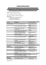
Figure 1 — The <strong>Huron</strong> system<br />
The <strong>Huron</strong> Digital Audio Convolution Workstation is an<br />
extremely powerful and modular general purpose signal<br />
processing engine for professional audio systems. It is designed<br />
around a 256 channel digital audio data bus. Interfacing with<br />
this bus are a combination of <strong>Huron</strong> Digital Signal Processing<br />
(DSP) boards and <strong>Huron</strong> Input and Output (I/O) boards. This<br />
specialised hardware is controlled by an industry standard PC<br />
host system.<br />
<strong>Huron</strong> specialises in — but is not limited to — applications<br />
which demand real time convolution, such as complex audio<br />
simulation and virtual reality audio. The <strong>Huron</strong> may be<br />
configured to process applications that require from two<br />
channels to more than 64 channels.<br />
Lake Software provides a simple graphical interface through<br />
which it is possible to run a variety of Lake designed audio<br />
engineering tools. Additionally, Lake provides a C++ Library<br />
interface for custom application programming.<br />
HURON TECHNICAL MANUAL PAGE 25
Features<br />
Applications<br />
Note: Any ISA or PCI card may be<br />
added to <strong>Huron</strong> workstations<br />
• Modular DSP and I/O architecture.<br />
• Internal 256 channel digital audio bus.<br />
• High performance parallel DSP architecture.<br />
INTRODUCTION TO THE HURON<br />
• Massive convolution with zero propagation delay.<br />
• Fast animating convolution.<br />
• General purpose, programmable DSP's, with zero wait state<br />
DRAM for memory intensive applications.<br />
• Professional quality analogue or digital audio interfaces.<br />
• Object oriented programming interface, with dynamic link<br />
libraries and DSP tools.<br />
• TCP/IP control from external workstations such as Silicon<br />
Graphics ® machines.<br />
• Virtual reality audio.<br />
• Animated auralisation, virtual walk-through acoustics.<br />
• Multi-speaker audio presentations.<br />
• Audio simulation and synthesis.<br />
• Room measurement and equalisation.<br />
• Multi-effects for audio post production.<br />
• Forensic audio.<br />
• Integrated sound reinforcement systems.<br />
• Audio workstation network.<br />
HURON TECHNICAL MANUAL PAGE 26
<strong>Huron</strong> Hardware Components<br />
The <strong>Huron</strong> Hardware<br />
The <strong>Huron</strong> is a stand-alone audio workstation which consists of<br />
the following components:<br />
• Chassis: The <strong>Huron</strong> Workstation comes in a chassis painted<br />
to specification. The chassis contains a high quality<br />
industrial power supply, cooling fans with filters, a 3.5 inch<br />
floppy disk drive, a CD-ROM drive and hard disk drives<br />
ordered to the user’s specification.<br />
• <strong>Huron</strong> Backplane: The standard <strong>Huron</strong> backplane contains<br />
four PCI bus connectors, seven ISA bus connectors, a dual<br />
PCI-ISA edge connector and seven 256 channel <strong>Huron</strong> bus<br />
connectors. The <strong>Huron</strong> 20 backplane consists of sixteen 16<br />
bit ISA bus connectors, two 32 bit PCI connectors, a Dual<br />
PCI-ISA edge connector and sixteen 256 channel <strong>Huron</strong> bus<br />
connectors.<br />
• Single Board IBM PC Compatible Computer with<br />
Embedded Video and an Ethernet Network Card, supporting<br />
RJ-45 and Coaxial BNC connectors.<br />
The <strong>Huron</strong> also consists of a user specified number of:<br />
• DSP Cards: The Lake Technology Card contains four<br />
Motorola® 56002 DSP processors, and Lake proprietary<br />
circuitry.<br />
• ADAT I/O cards: The ADAT I/O card has three ADAT<br />
optical input and output connectors providing a total of 24<br />
channels of digital I/O.<br />
• I/O carrier cards: The I/O carrier card has connectors to<br />
support up to 8 plug-in modules. It interfaces the I/O<br />
modules to the <strong>Huron</strong> bus.<br />
• 16 bit dual channel A/D Module.<br />
• 18 bit dual channel D/A Module.<br />
• AES/EBU Synchronous Digital Input Module.<br />
• AES/EBU Asynchronous Digital Input Module.<br />
• AES/EBU Digital Output Module.<br />
• 16 channel Patch Panel.<br />
• RME Hammerfall card for WavePlayer-2. This card<br />
provides 24 channels of ADAT optical I/O for interfacing<br />
with <strong>Huron</strong> ADAT I/O cards and other third party digital<br />
audio equipment.<br />
HURON TECHNICAL MANUAL PAGE 27
INTRODUCTION TO THE HURON<br />
• Optional ISA cards. Any ISA bus card may be optionally<br />
incorporated into the <strong>Huron</strong> system.<br />
• Optional PCI cards. Any PCI cards may be optionally<br />
incorporated into the <strong>Huron</strong> system.<br />
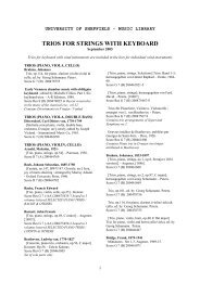
The following diagrams illustrate the <strong>Huron</strong> chassis (Figure 2<br />
and Figure 3). The system illustrated has a <strong>Huron</strong> ADAT I/O<br />
card in slot 0, a DSP card in slot 1, an I/O carrier card in slot 2,<br />
and a RME Hammerfall digital audio PCI card for use with the<br />
WavePlayer-2 application.<br />
Figure 2 — Front elevation of the <strong>Huron</strong>.<br />
1 Reset switch 14 Parallel port connector<br />
2 Keyboard lock 15 SVGA port Connector<br />
3 Power indicator 16 Mouse connector<br />
4 Hard disk indicator 17 COM1 connector<br />
5 Keyboard lock indicator 18 Keyboard connector<br />
6 Power switch 19 I/O connector<br />
7 Floppy disk drive 20 <strong>Huron</strong> ADAT I/O connectors<br />
8 CD-ROM Drive 21 Hammerfall SPDIF I/O and ADAT Sync connector<br />
9 Power Supply Unit 22 Hammerfall ADAT1 and ADAT2 I/O connectors<br />
10 Mains inlet 23 Hammerfall ADAT3 I/O connectors<br />
11 Mains outlet 24 Hammerfall Word Clock out connector<br />
12 Ethernet connector 25 Hammerfall Word Clock in connector<br />
13 COM2 connector<br />
HURON TECHNICAL MANUAL PAGE 28
↓ Setting up the Hardware<br />
Starting the <strong>Huron</strong><br />
↓ To start the <strong>Huron</strong> workstation<br />
(see Figure 3)<br />
Figure 3 — Rear elevation of the <strong>Huron</strong>.<br />
INTRODUCTION TO THE HURON<br />
You will need the following hardware before you can use the<br />
<strong>Huron</strong>:<br />
• 1 PS2 keyboard or AT keyboard with PS2 adaptor plug.<br />
• 1 PS2 Microsoft mouse (or compatible).<br />
• 1 SVGA screen with IEC mains extension lead.<br />
• 1 IEC mains lead.<br />
1. Connect the keyboard cable (with the adaptor if required) to<br />
the keyboard socket (18).<br />
2. Connect the mouse cable to the mouse socket (16).<br />
3. Connect the SVGA cable to the SVGA port (15).<br />
4. Plug the mains extension lead into the mains outlet of <strong>Huron</strong><br />
5. 11) and the mains inlet of the SVGA screen.<br />
6. Plug the mains cable into the <strong>Huron</strong> mains inlet (10).<br />
7. Unlock the front panel drive bay with the key provided. The<br />
disk drive and CD ROM drive should be empty.<br />
8. Turn on the SVGA screen then turn the power switch on.<br />
After an initial boot process, log onto Windows 2000.<br />
HURON TECHNICAL MANUAL PAGE 29
Installing New Hardware Components<br />
Note: Always observe anti-static<br />
precautions when handling electronic<br />
equipment.<br />
↓ Installing new DSP or I/O cards<br />
↓ Installing new I/O modules<br />
INTRODUCTION TO THE HURON<br />
New <strong>Huron</strong> cards and modules can be purchased to expand the<br />
capability of <strong>Huron</strong>. Qualified service personnel should<br />
perform the installation of these cards or modules.<br />
These guidelines should be followed when installing new cards:<br />
Addition and removal of all cards should only be attempted<br />
when the power to the <strong>Huron</strong> system is off. When installing a<br />
<strong>Huron</strong> ADAT I/O card, this should be installed in slot 0 (the<br />
leftmost slot when viewing the <strong>Huron</strong> from the front). When<br />
installing a new DSP or I/O carrier card, install it in the slot<br />
directly next to the last <strong>Huron</strong> DSP or I/O card. There should<br />
be no vacant slots between <strong>Huron</strong> DSP and I/O cards.<br />
Addition and removal of all modules should only be attempted<br />
when the power to the <strong>Huron</strong> system is off. When installing<br />
new I/O modules onto a <strong>Huron</strong> I/O carrier card, the position and<br />
orientation of the modules is very important. Input modules are<br />
always populated in module 8 first, followed by module 7, and<br />
so on. Output modules are always populated in module 1 first,<br />
followed by module 2, and so on. When inserting a new input<br />
module insert it in the highest available slot number. When<br />
inserting a new output module, insert it in the lowest available<br />
slot number. Always be careful to ensure the correct orientation<br />
of any modules. The orientation shown in Figure 4 must be<br />
adhered to for all modules. Special attention must also be paid<br />
to ensuring the module connector pins mate perfectly with the<br />
I/O base card connectors. Incorrect insertion of the modules<br />
could result in damage to the module and/or the workstation.<br />
HURON TECHNICAL MANUAL PAGE 30
Installing AT Add-In Cards<br />
If the <strong>Huron</strong> System does not work<br />
after the installation of an ISA card.<br />
↓ Check the following settings<br />
Figure 4 — Correct orientation of I/O module during installation<br />
INTRODUCTION TO THE HURON<br />
The <strong>Huron</strong> system is an AT compatible computing system.<br />
Standard ISA and PCI cards can be added to the system and<br />
configured for correct operation. The installation manuals for<br />
any add-in cards should be followed carefully to ensure their<br />
correct operation in the system.<br />
If the <strong>Huron</strong> system does not work after adding an AT<br />
compatible card to the system you should check the<br />
configuration of <strong>Huron</strong> and the add-in card. The most common<br />
problem is a conflict between an I/O ROM of an ISA add-in<br />
card and the address space used by the <strong>Huron</strong> system.<br />
• The <strong>Huron</strong> system has a floppy controller built in to the<br />
single board computer. Some SCSI cards have a floppy disk<br />
drive controller included. This additional SCSI drive<br />
controller should be disabled.<br />
• Check the base address of any RAM or I/O ROM on the AT<br />
add-in card. Some typical default base addresses for add in<br />
cards are 0xC800 for ethernet cards and 0xDC00 for SCSI<br />
cards.<br />
If you determine that the base addresses for the <strong>Huron</strong> system<br />
and the new add-in card overlap, then you must change one of<br />
the base addresses. Either follow the instructions in the<br />
installation manual of the new add-in card or change the <strong>Huron</strong><br />
base address as explained below.<br />
HURON TECHNICAL MANUAL PAGE 31
↓ To change the ISA memory<br />
address of the <strong>Huron</strong><br />
↓ To edit the registry settings<br />
INTRODUCTION TO THE HURON<br />
Altering the ISA base memory address of the <strong>Huron</strong> is a two<br />
stage process, it requires that:<br />
1. The Jumpers on the DSP card and I/O card are set to a new<br />
address.<br />
2. The <strong>Huron</strong> Windows 2000 Registry settings are altered to<br />
refer to the changed addresses.<br />
• Adjust the jumpers on the DSP card.<br />
JP2 is located on the bottom left hand corner of the DSP card.<br />
The base address can be located on any 0x0200 boundary, but<br />
should be confined to 0xD000-0xDE00 for AT compatible<br />
systems. The most significant 7 bits of the base address are set<br />
by JP2, with the most significant bit (MSB) on the bottom of<br />
the jumper block. When no jumper is installed on a bit position<br />
a logical “1” is set, while an installed jumper denotes a logical<br />
“0”.<br />
Below is a diagram of the jumper setting for the DSP card<br />
default base address of 0xD000. If you have any other cards in<br />
your computer, ensure they do not access the same address<br />
space as the <strong>Huron</strong>.<br />
Figure 5 — DSP card Jumper 2<br />
• Set the I/O carrier card to the same address as the DSP Card<br />
using JP 1 on the I/O carrier card.<br />
Below is a diagram of the I/O card jumper settings for the<br />
default base address of 0xD000.<br />
Figure 6 — I/O card Jumper 1<br />
After the <strong>Huron</strong> hardware base address has been changed, the<br />
<strong>Huron</strong> Windows 2000 Registry settings need to be edited to<br />
match this new base address.<br />
1. From the Windows 2000 Start Menu select Run.<br />
2. At the prompt type Regedit or Regedt32.<br />
3. Browse to the Registry Key<br />
HKEY_LOCAL_MACHINE\SYSTEM\CurrentControl<br />
Set\Services\lakekrnl\Parameters<br />
HURON TECHNICAL MANUAL PAGE 32
INTRODUCTION TO THE HURON<br />
4. Edit the IoMemoryMapBase value to the new values<br />
previously set on the card.<br />
5. Eg. 0xd0000 (the default address)<br />
HURON TECHNICAL MANUAL PAGE 33
↓ Connecting with the patch panel<br />
Connecting Audio Inputs and<br />
Outputs to the <strong>Huron</strong><br />
Audio inputs and outputs are connected to the <strong>Huron</strong> system via<br />
1U 19” rack-mount patch panels or ADAT optical connectors<br />
located on the <strong>Huron</strong> ADAT I/O card.<br />
Each patch panel is wired with 16 XLR connectors and one D62<br />
male connector. The gender of the XLR connectors used is<br />
tailored to the configuration of the I/O card with which the<br />
panel is intended to mate. Male connectors are used for outputs<br />
and female connectors are used for inputs. A typical example is<br />
shown in Figure 7. This panel is to mate with an I/O card with<br />
1-4 output modules and 1-4 input modules.<br />
Each IO module in the <strong>Huron</strong> will consume 2 input or output<br />
points on the patch panel regardless of whether they are<br />
analogue or digital.<br />
An analogue IO will output or take as input both left and right<br />
channels through two points on the connector panel, requiring<br />
two XLR connectors. For the example below these are<br />
represented by output points 1 and 2 and input points 13 and 14.<br />
A digital IO will output or take inputs for both the left and right<br />
channels though a single point on the connector panel, requiring<br />
only a single XLR connection. The input or output to the<br />
digital IO should be on the odd numbered connector. In the<br />
example below this is represented by the digital input 15 (the<br />
number 16 point is skipped or ignored).<br />
Figure 7 — The relationship between software and physical patch points<br />
HURON TECHNICAL MANUAL PAGE 35
↓ Connecting ADAT I/O<br />
Adding Additional I/O Cards<br />
INTRODUCTION TO THE HURON<br />
Each ADAT connection on the <strong>Huron</strong> ADAT I/O card (shown<br />
in Figure 3) carries 8 channels of digital audio data via optical<br />
TOSLINK connectors. When viewing the <strong>Huron</strong> from the rear,<br />
the first (top), third and fifth connectors are for audio inputs 1-<br />
8, 9-16, and 17-24 respectively, and the second, fourth and sixth<br />
(bottom) connectors are for audio outputs 1-8, 9-16, and 17-24<br />
respectively.<br />
If a second I/O carrier card is installed in the system of Figure 7<br />
its channels would be numbered from 17 to 32. To determine<br />
which physical patch panel inputs and outputs belong to those<br />
shown in the configuration window, the configuration numbers<br />
should be converted to modulo 16.<br />
For further information regarding the pin outs of the patch panel<br />
connectors see <strong>Huron</strong> Hardware Specifications.<br />
HURON TECHNICAL MANUAL PAGE 36
<strong>Huron</strong> System Tools<br />
<strong>Huron</strong> Simulation Tools<br />
<strong>Huron</strong> Engineering Tools<br />
The <strong>Huron</strong> Software Components<br />
<strong>Huron</strong> software is distributed in the following packages.<br />
The <strong>Huron</strong> System Tools package forms the basis of the <strong>Huron</strong><br />
system software. Central to the System Tools is the virtual rack<br />
or VRack. The VRack provides a standard interface through<br />
which users are able to load various signal processing<br />
applications. The System Tools also include a Patch Bay for<br />
connecting application modules and physical inputs and<br />
outputs, and an Input Output Manager for controlling gain and<br />
the configuration of hardware.<br />
Lake Technology’s simulation tools are designed for use in<br />
audio simulations. Designed to complement Virtual Reality<br />
applications, the simulation tools can be chosen for either arrays<br />
of speakers or headphones. Tools such as Space Array and<br />
Binscape are provided as an interface through which sound<br />
sources and virtual Soundscapes may be controlled via TCP/IP.<br />
Additional tools provide access to sound playback and effects<br />
such as speaker panning.<br />
The <strong>Huron</strong> Engineering Tools are designed for audio research<br />
purposes. Applications include: a Convolver which allows the<br />
use of long low latency Finite Impulse Response (FIR) filters; a<br />
Measurement tool which provides a means of recording the<br />
impulse response of linear systems (such as audio processors<br />
and large acoustic spaces); and a set of tools for plotting<br />
generating and formatting data files in the SIM file format used<br />
by all Lake software.<br />
HURON TECHNICAL MANUAL PAGE 37
<strong>Huron</strong> Programming Tools<br />
Lake Software Design Service<br />
INTRODUCTION TO THE HURON<br />
Lake provides the Programming Tools for customers who wish<br />
to design their own specific DSP and application programs. A<br />
C++ DSP Programmers Library is provided, allowing<br />
customers to develop their own DSP algorithms and<br />
applications on the <strong>Huron</strong> platform. Alternatively, C++ classes<br />
are provided which enable application programmers to<br />
incorporate Lake developed algorithms into custom-built<br />
applications. Version 3.2 of the programming tools includes a<br />
Matlab® interface which enables Matlab 5.2 or 5.3 (32 bit<br />
versions) users to compose and run scripts which utilise the<br />
<strong>Huron</strong> hardware for the Measurement and Convolution of audio<br />
data.<br />
Lake also offers a design contract service to build specific<br />
<strong>Huron</strong> applications to meet customer requirements. Contact<br />
Lake Technology for more information on custom designed<br />
software.<br />
HURON TECHNICAL MANUAL PAGE 38
General Installation<br />
↓ To install the <strong>Huron</strong> license<br />
↓ To install <strong>Huron</strong> VRack<br />
software.<br />
<strong>Huron</strong> Software Version 3.2<br />
Installing New Software Components<br />
Software components for the <strong>Huron</strong> come on a CD. Along with<br />
the CD is a licence floppy disk, which “enables” the software<br />
components you have purchased.<br />
Each of the software components supplied for <strong>Huron</strong> are<br />
installed from Windows 2000 in the same way: the order of<br />
installation must be the Software Licence first, the <strong>Huron</strong><br />
Software second, and any upgrades or patches last.<br />
1. Start Windows 2000<br />
2. Insert the Licence diskette into drive A:\<br />
3. Click the Start button, then select Run…. When the Run<br />
dialogue box appears, enter A:\setup where, A:\ is the drive<br />
letter of the Floppy Disk Drive.<br />
Follow the on screen instructions to complete the license<br />
installation.<br />
1. Start Windows 2000<br />
2. Insert the Installation CD in the CD-ROM drive.<br />
3. Click the Start button, then select Run…. When the Run<br />
dialogue box appears, enter [CD]:\setup where [CD] is the<br />
drive letter of your CD-ROM drive.<br />
4. Click OK.<br />
Follow the instructions that appear on the screen.<br />
The <strong>Huron</strong> Software installation will modify your <strong>Huron</strong>’s<br />
configuration files.<br />
After the installation, the <strong>Huron</strong> needs to be restarted for these<br />
changes to take effect. A dialogue box will appear to confirm<br />
the restart of the computer.<br />
HURON TECHNICAL MANUAL PAGE 39
↓ Changes to the Windows 2000<br />
Environment<br />
↓ Changes to Path Variable<br />
↓ Update the Windows 2000<br />
Registry<br />
↓ When using Matlab<br />
Programming Tools<br />
INTRODUCTION TO THE HURON<br />
The following environment variable will be added to your<br />
Windows 2000 Environment Variable List if you choose the<br />
default installation directory of C:\<strong>Huron</strong>32.<br />
LAKE-CFG C:\<strong>Huron</strong>32<br />
The following path will be added to your Windows 2000 Path<br />
Environment Variable if you choose the default installation<br />
directory of C:\<strong>Huron</strong>32.<br />
PATH C:\<strong>Huron</strong>32\Bin<br />
The <strong>Huron</strong> 3.2 installation will also update information in the<br />
Windows 2000 Registry.<br />
When using the Matlab programming tools it is important that<br />
the Windows 2000 path environment variable includes the<br />
Matlab binary directory eg. C:\Matlab\Bin<br />
The Matlab application should also include in its path variable<br />
the following:<br />
C:\<strong>Huron</strong>32\Bin<br />
C:\<strong>Huron</strong>32\<strong>Huron</strong>mat<br />
C:\<strong>Huron</strong>32\Examples\Matlab<br />
HURON TECHNICAL MANUAL PAGE 40
Introduction to the System Tools<br />
The System tools serve as the framework for all <strong>Huron</strong> software<br />
applications. They provide a standard interface for:<br />
• Configuring the physical input and output modules;<br />
including the naming of signals, the setting of input and<br />
output volumes and the manipulation of preamplifier gains.<br />
• Digitally connecting these physical inputs and outputs to the<br />
inputs and outputs of DSP application programs.<br />
• Starting and stopping applications, and controlling their onscreen<br />
visibility.<br />
The heart of the system software is the Virtual Rack or VRack.<br />
The VRack provides a graphical user interface based upon the<br />
metaphor of a “19-inch audio rack”. All DSP applications are<br />
available to the user as VRack mountable units. Each of these<br />
units may contain a number of input and output connectors.<br />
To connect the physical inputs and outputs to these DSP<br />
application input and output connectors, the Patch Bay is used.<br />
The Patch Bay provides a mechanism for connecting virtual<br />
cables between input and output points. This patching can<br />
occur between the physical inputs or outputs and DSP<br />
applications, or between DSP applications.<br />
Rather than provide individual volume controls within each<br />
DSP application, the <strong>Huron</strong> System Tools consolidate the<br />
volume controls in the IO Manager. This tool provides a<br />
volume control slider for each physical input or output. A<br />
radio-button control can be used to select the preamplifier gain<br />
for the input channels. When combined, these controls allow<br />
signal levels to be matched to the full-scale of the digital<br />
domain thus maximising the digital signal to noise ratio.<br />
HURON TECHNICAL MANUAL PAGE 41
Introduction<br />
Features<br />
The VRack Tool<br />
The “Virtual rack” or VRack application is the launch point for<br />
Lake Technology’s audio processing software. The VRack is<br />
designed to be analogous with a standard 19” audio rack system<br />
found in professional audio installations. It allows the user to<br />
construct a multitude of signal processing configurations, by<br />
adding virtual rack units to the graphical rack.<br />
The centralisation of controls within the VRack means that all<br />
software tools are accessible from a single interface.<br />
• Provides an interface to manage Lake Technology’s<br />
software tools.<br />
• Checks hardware configuration and allows the setting of<br />
channel names.<br />
• Provides a visual indicator of the total number of DSPs<br />
available in the system, and the current number initialised.<br />
• Allows the saving of the current workspace for subsequent<br />
recall.<br />
HURON TECHNICAL MANUAL PAGE 43
Operation<br />
Starting<br />
↓ To start the VRack tool<br />
Figure 8 — The VRack Interface<br />
THE SYSTEM TOOLS<br />
The VRack tool is started from the Windows 2000 Start Menu.<br />
1. From the Start Menu select <strong>Huron</strong> 3.2.<br />
2. Click on VRack.<br />
After the splash screen appears, the VRack will<br />
start.<br />
At the top of the VRack is the Rack Menu. This menu is used<br />
to select configurations, set various user options and exit the<br />
VRack. The menu is also used for putting new rack units into<br />
the VRack itself.<br />
Menu Item Contains<br />
File Options for saving, loading and naming VRack<br />
workspace configurations.<br />
Options Review the hardware configuration, and adjust the<br />
properties of the VRack.<br />
New Loads the virtual rack modules into the VRack.<br />
In the centre of the VRack are the Rack Spaces. When a DSP<br />
software or engineering application is launched, an icon<br />
representing the program will fill one of the spaces, these icons<br />
are known as Rack Panels.<br />
Each rack panel describes an application using a word and a<br />
symbol. These word/symbol associations are used throughout<br />
the DSP tool suites to allow quick visual identification of<br />
programs and their function. Each panel also has an Indicator<br />
HURON TECHNICAL MANUAL PAGE 44
Checking Configuration<br />
↓ To check configuration<br />
THE SYSTEM TOOLS<br />
LED. This LED is off when the DSP program is hidden but<br />
running off-screen, and set to bright green when the DSP<br />
program window is displayed on the screen.<br />
There are an unlimited number of rack spaces in the VRack. If<br />
many DSP programs are launched the VRack display space may<br />
become full. Once the on screen portion of the VRack is full,<br />
all subsequently launched program panels are placed<br />
underneath those shown in the VRack. To access these panels<br />
use the Rack Space Scrollbar to bring the unseen portion of<br />
the VRack into view.<br />
The DSP Meter at the bottom of the VRack provides a visual<br />
indication of the number of DSPs initialised by the software.<br />
The meter describes what proportion of the DSP processors in<br />
the system are in use. To the right of this ratio is a graphical<br />
meter providing a proportional view of DSP usage.<br />
The VRack may be used to review what Lake hardware is<br />
installed in the system.<br />
From the VRack Menu.<br />
1. Select Options.<br />
2. Select Configure.<br />
This produces the following window:<br />
Figure 9 — The VRack Configuration Panel<br />
The right hand side of the window shows a summary of the<br />
hardware installed on the system.<br />
HURON TECHNICAL MANUAL PAGE 45
Configuration Functions<br />
Internal/External<br />
Sampling Rate<br />
Base Address<br />
No. Boards<br />
DSP Boards<br />
Processors<br />
IO Boards<br />
ADAT Boards<br />
IO Channels<br />
↓ To set the name of a channel<br />
THE SYSTEM TOOLS<br />
The system sampling clock source can be selected from either<br />
the internal system clock, or an external clock derived from a<br />
digital input source. For an external clock to be selected the<br />
system must have the <strong>Huron</strong> ADAT card positioned in slot 0 or<br />
digital inputs on channels 15 and 16. No DSP resources can be<br />
in use while the switch is being made.<br />
The current sampling rate is displayed. If an external clock is<br />
selected, the clock source must be stable when the external<br />
selection is made. This frequency is assumed to never change<br />
after external is selected.<br />
The physical memory address in the PC where the Lake<br />
hardware resides.<br />
The total number of Lake boards installed in the system.<br />
The total number of DSP boards installed in the system.<br />
The total number of DSP processors installed in the system.<br />
The total number of Input/Output (I/O) boards installed in the<br />
system.<br />
The total number of <strong>Huron</strong> ADAT boards installed in the<br />
system.<br />
The total number of physical I/O channels in the system.<br />
The left side of the configuration window contains a listbox<br />
displaying the names of all the physical Input and Output<br />
channels. The first time VRack is run these names will be set to<br />
the factory defaults. The Scrollbar to the right of the listbox can<br />
be used to scroll through this list.<br />
The names of the channels may be set by the user.<br />
• Double click on the channel name which is to be changed.<br />
The following window appears:<br />
Figure 10 — Channel Name Setting<br />
HURON TECHNICAL MANUAL PAGE 46
Tip: Channel Names are saved along<br />
with workspaces (*.WSP) and will be<br />
restored when a workspace is<br />
reloaded.<br />
Configuration<br />
↓ To set VRack to always on top<br />
↓ To restore VRack’s normal -<br />
behaviour<br />
Launching Tools<br />
↓ To launch an application or<br />
DSP tool<br />
Note: It is possible to have more than<br />
one instance of a particular tool in the<br />
VRack at a time, (eg. the Convolver).<br />
If an attempt is made to run more<br />
than one copy of a program which<br />
does not allow multiple instances (eg.<br />
the Patch Bay), VRack will not load<br />
the program into the VRack.<br />
THE SYSTEM TOOLS<br />
• Type a new name into the Name field.<br />
Pressing the OK button will save the new name.<br />
— or —<br />
Pressing Cancel will cancel the name change.<br />
Once a channel has been assigned a name, all software will<br />
show the new name of that channel. The appropriate naming of<br />
channels mapped to physical input and output devices makes<br />
the identification of specific channels or devices within DSP<br />
applications simpler.<br />
• After setting channel names, pressing the OK button in the<br />
Configure Window will keep any new channel names.<br />
Pressing Cancel will restore all channel names to their<br />
previous settings.<br />
The VRack can be configured to always be at the forefront of<br />
the desktop.<br />
From the VRack Menu.<br />
1. Select the Options menu.<br />
2. Click Always on top.<br />
• Repeat the menu selections shown above.<br />
The VRack is used to start all applications or DSP tools.<br />
1. Select New from the Rack menu.<br />
2. Select the tool you require from the set of tool groups which<br />
appear in the drop down menu.<br />
The selected tool will be placed into the VRack interface, where<br />
it can be accessed by a single click.<br />
HURON TECHNICAL MANUAL PAGE 47
Displaying, Hiding and Terminating Tools<br />
↓ To display a DSP tool<br />
↓ To hide a DSP tool<br />
Note: Hiding the tool does not<br />
terminate the DSP tool and its<br />
functions<br />
↓ To terminate a DSP tool and<br />
remove it from the VRack<br />
Workspaces<br />
↓ To save a workspace<br />
THE SYSTEM TOOLS<br />
When a DSP tool is first placed into the VRack, only its rack<br />
panel can be seen. In order to adjust the settings of the tool it<br />
needs to be displayed.<br />
• Click on the tool’s rack panel in VRack.<br />
The window representing the selected DSP tool will appear, and<br />
the Indicator LED on the VRack panel will change to bright<br />
green. This change indicates that the DSP tool is now<br />
displayed.<br />
Either:<br />
• Click on the rack panel of the tool you wish to hide<br />
— or —<br />
Click on the at the top right corner of the DSP tool.<br />
The rack panel’s Indicator LED will darken, and the application<br />
window will be hidden.<br />
1. Display the DSP tool by clicking on its rack panel.<br />
2. Select Close from the DSP tool’s system menu (<br />
top right of the tool).<br />
The tool will terminate, relinquish its DSP resources and<br />
remove itself from the VRack.<br />
at the<br />
The VRack can be made to save the current set of DSP tools,<br />
the current Patch Bay settings, and the Input and Output settings<br />
in the rack space. This enables the VRack to be restarted with<br />
the same configuration as when it was saved. Additionally, the<br />
DSP tools will be restarted in their current state. These save<br />
files are known as workspace files (*.WSP).<br />
From the VRack Menu.<br />
1. Select File.<br />
2. Select Save.<br />
This will save the workspace under the current workspace<br />
name. If no name has been given to the workspace, you will be<br />
prompted with a Save As… dialogue box, See Below.<br />
It is possible to save multiple workspace configurations by<br />
saving each workspace configuration under a new workspace<br />
name.<br />
HURON TECHNICAL MANUAL PAGE 48
↓ To save a workspace under a<br />
new name<br />
↓ To load a saved workspace<br />
THE SYSTEM TOOLS<br />
From The VRack Menu.<br />
1. Select the File Menu.<br />
2. Select Save As…<br />
3. This activates the Save As… dialogue box (see Figure 11),<br />
which allows the creation of a name under which the<br />
workspace file will be saved.<br />
Figure 11 — The VRack Save As dialogue box<br />
4. In the File Name box enter the name you wish to save the<br />
workspace as.<br />
5. Click OK to save the workspace.<br />
The VRack configuration will be disassembled, saved and then<br />
restored from the file.<br />
From the VRack Menu.<br />
1. Select the File Menu.<br />
2. Select Open.<br />
3. Select the required saved workspace from the listbox.<br />
4. Click OK to load the workspace.<br />
Alternatively, you can create a new icon with the saved<br />
workspace file in the command line. After creating this new<br />
icon you can automatically restore all of the DSP and Input and<br />
Output settings in the workspace, by Double clicking on the<br />
shortcut.<br />
The command line required to launch the VRack application<br />
and an associated workspace file is:<br />
C:\<strong>Huron</strong>32\VRack32.exe [drive and path to<br />
wsp file]\[name of wsp file].wsp<br />
HURON TECHNICAL MANUAL PAGE 49
Stopping VRack<br />
↓ To exit the VRack, and<br />
terminate all of the DSP tools<br />
Summary<br />
THE SYSTEM TOOLS<br />
From the VRack Menu<br />
1. Select File.<br />
2. Select Exit.<br />
Each DSP tool will automatically be terminated and the VRack<br />
will close down.<br />
• The VRack is the core Lake Technology software<br />
application. It manages all of the DSP tools, controlling the<br />
starting, display and hiding of each one.<br />
• VRack provides a visual indication of all tools which are<br />
running and the amount of DSP processing power utilised<br />
and available in the current configuration.<br />
• VRack can save the current DSP tool configuration in a<br />
workspace file, allowing the VRack to start up and appear<br />
just as it was, when it was last saved.<br />
HURON TECHNICAL MANUAL PAGE 50
Introduction<br />
Features<br />
Operation<br />
Starting<br />
↓ To restart the Patch Bay<br />
The Patch Bay<br />
The Patch Bay is used to connect or patch audio between<br />
physical inputs and outputs and the Lake Technology<br />
applications. It provides a graphical representation of the<br />
connections between the DSP tools loaded into the VRack and<br />
the physical inputs and outputs present in the system.<br />
• Connects audio signals from physical inputs and outputs to<br />
DSP tools.<br />
• Connects audio signals between DSP tools.<br />
• Provides a graphical representation of all audio connections<br />
in the system.<br />
Figure 12 — The Patch Bay interface<br />
The Patch Bay is loaded automatically when VRack starts.<br />
However, provision exists for the Patch Bay to be reloaded<br />
from the VRack should it terminate due to a system error.<br />
HURON TECHNICAL MANUAL PAGE 51
Patching<br />
↓ To connect a pair of patch<br />
points<br />
↓ To connect multiple patch<br />
points, in series<br />
THE SYSTEM TOOLS<br />
From the VRack Menu.<br />
1. Select the New Menu.<br />
2. Select the Engineering Tools Submenu.<br />
3. Select the Patch Bay icon.<br />
The Patch Bay is divided into smaller areas called patchsets.<br />
Each patchset represents all the inputs and outputs; of a<br />
particular DSP tool, the set of physical inputs or, the set of<br />
physical outputs.<br />
Within each patchset there exists a number of patch points.<br />
Each patch point represents either an input or an output and can<br />
be connected via a graphical patch cable to another patch point.<br />
Patch points are the virtual equivalents of the XLR connectors<br />
found on audio hardware.<br />
Each DSP tool patchset may be assigned a name from the Patch<br />
Bay. This name will appear in the DSP tool name section of<br />
the display.<br />
Scroll pins on the physical input and output patchsets allow the<br />
pinning of the patchset. When a patchset is pinned it will not<br />
scroll when the Patch Bay’s scrollbar is used.<br />
The connection of audio between two patch points is done by<br />
selecting pairs of patch points.<br />
1. Click on the first patch point.<br />
2. The patch point will turn red signifying it has been selected.<br />
3. Click on the second patch point.<br />
If compatible, the two patch points will be connected by a<br />
patch cable.<br />
1. Click on a set of patch points.<br />
The patch points will stay red indicating they are all selected.<br />
2. Click on the first point in the series that you wish to connect<br />
the original patch points to.<br />
The patcher will connect the patch points in series.<br />
Figure 13 — An example of multiple patching<br />
HURON TECHNICAL MANUAL PAGE 52
Valid Patching<br />
↓ To de-select a selected patch<br />
point<br />
THE SYSTEM TOOLS<br />
A valid patch is a patch made between two differing patch point<br />
types, which can be recognised in the patcher:<br />
white)<br />
Legal Patches<br />
From<br />
To<br />
Physical Input DSP tool input<br />
DSP tool output DSP tool input<br />
DSP tool output Physical output<br />
Physical input or DSP tool output (graphical XLR 'pins' are<br />
Physical output or DSP tool input (graphical XLR 'holes'<br />
are black)<br />
When a valid patch has been made, a patch cable is drawn<br />
between the two patch points indicating that they have been<br />
patched together, and both patch points will become black in<br />
colour.<br />
• Click on the red selected patch point a second time.<br />
The patch point will return to its usual colour and a new<br />
selection may be made.<br />
Only the following patches are legal. Attempts to patch illegal<br />
patch points together results in an audible beep being sounded<br />
from the system and the patch request being ignored.<br />
In addition, only some patch points may have more than one<br />
patch cable attached:<br />
Type of Patch Point Allows<br />
DSP input Only one cable attached<br />
Physical output Only one cable attached<br />
DSP output Multiple cables attached<br />
Physical input Multiple cables attached<br />
If a new DSP tool is started, the Patch Bay will automatically<br />
add a new patchset. Conversely, if a DSP tool is stopped, the<br />
patchset will disappear.<br />
Some DSP tools also change their number of inputs and outputs<br />
during the course of their execution. The Patch Bay notices any<br />
changes in DSP tool channels and adjusts itself accordingly.<br />
Sometimes patchpoints will appear as though they are<br />
connected (black) but will not have a patch cable connecting<br />
them to anything. These points are “hidden” and are in use<br />
when the Patch Bay is in an alternate state (this effect can be<br />
seen when switching between Convolver programs that have<br />
different numbers of filters). It is possible to deselect and<br />
HURON TECHNICAL MANUAL PAGE 53
Tip: Even if two patch points are<br />
connected, you may need to adjust<br />
gain settings and other parameters of<br />
the DSP tool before any sound is<br />
actually heard.<br />
Unpatching<br />
↓ To remove a patch cable from a<br />
patch point<br />
Note: If there are multiple patch<br />
cables attached to the patch point that<br />
is double clicked then all patch cables<br />
attached to that patch point are<br />
unpatched and removed.<br />
Naming DSP Tools<br />
↓ To name a DSP tool<br />
Note: The name in the Name section of<br />
a DSP tool will not save multiple<br />
words separated by spaces. To<br />
separate words use an underscore<br />
or<br />
hyphen.<br />
Scrolling<br />
THE SYSTEM TOOLS<br />
repatch these points, however this removes the alternate state<br />
settings.<br />
• Double click on one of the patch points of the patch cable to<br />
be removed. The patch point should not have been<br />
previously selected (ie. not red but black) before double<br />
clicking.<br />
The Patch Bay allows the user to assign a name to each of the<br />
DSP tools currently running. This function can be useful when<br />
more than one of the same DSP tool is loaded into the VRack.<br />
1. Type the new<br />
name into the<br />
DSP tool name<br />
area.<br />
2. Press Enter.<br />
Figure 14 — DSP tool naming<br />
The caption in the DSP tool name area will change.<br />
When there are many patchsets or physical inputs and outputs,<br />
then the Patch Bay window may be scrolled up and down to<br />
bring hidden patchsets into view. Scrolling the window does<br />
not de-select a previously selected patch point. Thus, it is<br />
HURON TECHNICAL MANUAL PAGE 54
↓ To pin a patchset<br />
↓ To unpin a patchset<br />
Summary<br />
THE SYSTEM TOOLS<br />
possible to patch a patch point located at the top of the window<br />
to one at the bottom of the window by selecting the first patch<br />
point, scrolling the window, and then selecting the second patch<br />
point. Scrolling of the window is done using the scrollbar at the<br />
right hand side of the Patch Bay.<br />
The physical input and output patchsets also have a feature<br />
where they may be pinned to the window. When a patchset is<br />
pinned, it does not scroll when the Patch Bay window is<br />
scrolled.<br />
• Click on the pin symbol or<br />
the arrows next to the pin.<br />
The symbol will change to the pinned symbol, and the patchset<br />
will be pinned.<br />
• Click on the pinned symbol or the arrows next to the pinned<br />
symbol.<br />
The symbol will change to the pin symbol and the patchset will<br />
be unpinned.<br />
• The Patch Bay allows the audio patching of DSP tools,<br />
physical inputs and physical outputs, by graphically<br />
selecting two patch points with the mouse.<br />
• Patches are shown on the Patch Bay as lines between patch<br />
points, these lines are known as patch cables.<br />
• The Patch Bay updates itself as DSP tools are started and<br />
stopped.<br />
• DSP tools may be assigned a name using the Patch Bay.<br />
HURON TECHNICAL MANUAL PAGE 55
Introduction<br />
Features<br />
The IO Manager<br />
The IO Manager is used to adjust the gain levels of the system’s<br />
physical analogue inputs and outputs. The IO Manager also<br />
provides status information for the systems digital inputs and<br />
outputs.<br />
• Allows volume adjustments of analogue inputs and outputs.<br />
• Allows the setting of the gain for analogue inputs.<br />
• Provides a graphical overview of all physical analogue<br />
inputs and outputs, their associated volumes and input gain<br />
levels.<br />
• Provides access to the status of digital inputs.<br />
• Allows the mode selection of digital outputs.<br />
HURON TECHNICAL MANUAL PAGE 57
Operation<br />
Starting<br />
↓ To access the IO Manager<br />
Figure 15 — The IO Manager interface<br />
THE SYSTEM TOOLS<br />
The IO Manager is started automatically when VRack is<br />
launched.<br />
• Click on the IO Manager icon from the VRack.<br />
The IO Manager is divided into two areas:<br />
Physical outputs are placed at the top of the window<br />
Physical inputs are placed at the bottom.<br />
Each slider represents a physical Input or Output installed<br />
within the system.<br />
Each slider lists the physical channel number that it controls<br />
and the current volume setting in dB. Additionally, analogue<br />
inputs have pre-amp gain levels which may applied.<br />
HURON TECHNICAL MANUAL PAGE 58
Adjusting Volumes<br />
↓ To adjust the volume of a given<br />
channel<br />
Adjusting Input Level Gain<br />
↓ To adjust the input gain level of<br />
an input channel<br />
Note: The volume and input level<br />
settings are effective throughout the<br />
system, and will be saved when the<br />
current workspace is saved.<br />
Muting an Output<br />
↓ To mute an output channel<br />
↓ To unmute an output channel<br />
↓ To mute all outputs<br />
↓ To unmute all outputs<br />
Either<br />
Figure 16 — Controls for adjusting volume<br />
THE SYSTEM TOOLS<br />
• Click the on the Volume slider bar to select the desired<br />
volume level.<br />
— or —<br />
Drag the Volume slider bar to the desired level.<br />
— or —<br />
Type in a volume level from -30 to +30 dB.<br />
• Click on the desired input gain level.<br />
The current gain level will be set to the level indicated by the<br />
graphical switch.<br />
• Click on the Mute box above the channel to mute.<br />
• Click on the Mute box above the channel which is muted.<br />
• Click Mute All.<br />
• Click the previously selected Mute All.<br />
HURON TECHNICAL MANUAL PAGE 59
Viewing Digital Input Status<br />
↓ To view the status of a digital<br />
input<br />
THE SYSTEM TOOLS<br />
1. Check the colour of the digital input status LED. It will be<br />
green when no input errors are detected, yellow when nonfatal<br />
input errors are detected and red when fatal errors are<br />
detected.<br />
2. Click the LED to activate a status window.<br />
Figure 17 — Digital input status<br />
Lake Technology’s software reports nine error conditions that<br />
may occur on digital input channels.<br />
Error Reported Description<br />
No Error The digital input system is not producing any errors.<br />
Validity bit high The input is working, but audio input is not being<br />
generated (eg. Pause or Stop has been pressed on the<br />
input device).<br />
Confidence lag The input signal has a high rate of noise, or is not of<br />
good quality.<br />
Slipped Sample An uncompensated difference in the sampling rates of<br />
the input device and the DSP machine are causing loss<br />
or duplication of samples.<br />
CRC error Professional inputs only - a CRC error has been<br />
detected in the channel status signal.<br />
Parity Error Parity checking has returned an error.<br />
Bi-Phase coding A signal is being produced on the input, but it does not<br />
have the correct format.<br />
No PLL Lock The line is receiving no signal whatsoever.<br />
Unknown error Error condition unknown.<br />
Setting Digital Output Format<br />
Some digital outputs can be encoded by Lake equipment in<br />
either a professional or consumer format. Each format uses<br />
different codes for the channel status bits placed in the digital<br />
output stream. The digital output from the Lake system should<br />
thus be set in accordance to the format of the equipment<br />
accepting the digital output.<br />
HURON TECHNICAL MANUAL PAGE 60
↓ To set a digital output to<br />
professional or consumer output<br />
Grouping Volume Sliders<br />
↓ To group volume sliders<br />
together<br />
Showing Channels in a Group<br />
↓ To determine if a channel is part<br />
of a group<br />
THE SYSTEM TOOLS<br />
• Click the Pro or Con digital output toggle to select either<br />
Professional format or Consumer format.<br />
The toggle will move to indicate your selection.<br />
Figure 18 – The IO Manager channel manipulation features<br />
1. Click the Channel Number Boxes of all the channels to be<br />
grouped. As each Channel Number box is clicked it will<br />
highlight.<br />
2. Click the Group box.<br />
The Grouped Sliders will all be set to the volume level of the<br />
lowest numbered slider in the group, with inputs having<br />
precedent over outputs.<br />
When grouped, changes to the volume of one slider will affect<br />
all sliders in the group.<br />
1. Click the Channel Number Box of the channel whose<br />
group you wish to determine. The box will highlight.<br />
2. Click the Show Box.<br />
All channels in the same group as the highlighted Channel<br />
Number Box will be highlighted.<br />
HURON TECHNICAL MANUAL PAGE 61
Removing Channels from a Group<br />
↓ To remove channels from a<br />
group<br />
Splitting Channels<br />
↓ To split volume controls to a<br />
new window<br />
Split Windows<br />
↓ To change the name of a split<br />
window<br />
THE SYSTEM TOOLS<br />
1. Click the Channel Number Box of the channels to remove<br />
from a group.<br />
2. Click the Ungroup Box.<br />
Input and output sliders can be cloned from the IO Manager<br />
panel into their own window. This splitting of channels allows<br />
the user to focus on controlling the gain of selected channels.<br />
1. Click the Channel Number Box of the channels to be split.<br />
Each click should highlight a channel.<br />
2. Click the Split Button. All of the channels in the selected<br />
group will re-appear in their own window.<br />
Figure 19 — Split volume control window<br />
Split channels appear in a separate window. They behave in the<br />
same way as normal volume adjustment channels, with the<br />
exception that you cannot group from, or split from, a<br />
previously split window.<br />
1. Click in the title box of the split window.<br />
2. Type a new name for the split window.<br />
3. Press Enter.<br />
HURON TECHNICAL MANUAL PAGE 62
↓ To close a split window<br />
Summary<br />
THE SYSTEM TOOLS<br />
• Click the system menu box in the top left hand corner of the<br />
window.<br />
• The IO Manager is used for setting input and output gain<br />
levels, viewing digital input status, and setting digital output<br />
format.<br />
• The current values of channel volumes can be read<br />
graphically and textually in the IO Manager.<br />
HURON TECHNICAL MANUAL PAGE 63
Introduction to the Simulation Tools<br />
The simulation tools are comprised of a number of separate<br />
VRack applications that provide simulation of threedimensional<br />
acoustic spaces over an array of speakers or a set<br />
of headphones.<br />
Binscape: Which provides facilities for simulating virtual<br />
acoustic spaces with multiple moving sound sources. Binscape<br />
uses binaural processing and optimised panning algorithms to<br />
provide high-end positional audio over headphones.<br />
Space Array: Which provides facilities for simulating multiple<br />
moving sound sources and three-dimensional virtual acoustic<br />
spaces. Featuring an optimised panning algorithm for speaker<br />
arrays, Space Array has an enlarged sweet spot and is suitable<br />
for personal or group presentations.<br />
AniScape: Which provides facilities for simulating threedimensional<br />
virtual sound spaces, where a single user can hear<br />
multiple moving sources through a speaker array or<br />
headphones. Aniscape is made up of a number of individual<br />
simulation tools, including Sound Field Filter, Speaker<br />
Decoder, and Binaural Decoder. Binscape and Space Array<br />
have superseded Aniscape for most simulation applications.<br />
MultiScape: Which provides facilities for simulating threedimensional<br />
virtual acoustic spaces, where multiple users can<br />
hear multiple moving sources by using a speaker array or<br />
headphones. Binscape and Space Array have superseded<br />
Multiscape for most simulation applications.<br />
HeadScape: Which provides facilities for using long, low<br />
latency FIR filters in combination with a head tracking device.<br />
This combination allows HeadScape to produce very accurate<br />
three-dimensional sound for high-end acoustic simulations.<br />
Sonic Animator: Which provides a graphical interface and<br />
panning tool for manipulating audio sound source location.<br />
Lake Technology provides a selection of Other simulation tools<br />
which integrate with the above tools and other Lake<br />
Technology VRack applications. These other tools include:<br />
Locator: Designed for testing and configuration verification,<br />
the Locator provides a visual interface to allow the positioning<br />
and movement of sound objects on a two dimensional plane.<br />
WavePlayer-2: An enhanced version of WavePlayer for play<br />
back of long duration Wave files (*.WAV) with zero <strong>Huron</strong><br />
DSP usage.<br />
WavePlayer: Designed to play back Wave files (*.WAV)<br />
encoded in the *.SIM file format through the <strong>Huron</strong> system.<br />
Tracker: Allows the <strong>Huron</strong> to interface with a threedimensional<br />
position tracking system such as the Polhemus®<br />
HURON TECHNICAL MANUAL PAGE 65
THE SIMULATION TOOLS<br />
InsideTrak, Fasttrak, Ascension Flock Of Birds, Intersense IS-<br />
300, IS-600, IS-900, InterTrax (serial) and InterTrax-2 (USB).<br />
Please contact Lake Technology for further information about<br />
<strong>Huron</strong> tracker interfaces.<br />
Socket: Enables the remote control of a <strong>Huron</strong> system via<br />
TCP/IP control packets from a remote devide. The <strong>SNAP</strong><br />
protocol is used for communication with Socket.<br />
MakeRoom: A windows application designed for the statistical<br />
generation of virtual rooms. These rooms are designed for use<br />
with the Simulation Tools or the Engineering Tools<br />
applications.<br />
In addition to VRack applications, Lake Technology provides<br />
the following API for controlling Simulation Tools VRack<br />
applications.<br />
<strong>SNAP</strong>: An API for controlling the <strong>Huron</strong> from an external<br />
application. The external application can be located on the<br />
<strong>Huron</strong> or another computer on the local network.<br />
HURON TECHNICAL MANUAL PAGE 66
An overview of the Simulation Tools<br />
Lake Technology’s Simulation Tools provide a wide range of<br />
options for configuring and creating aural simulations. This<br />
multitude of potential configurations provides not only a wealth<br />
of possibilities for aural simulations but introduces a level of<br />
complexity to the running of such simulations.<br />
In order to reduce possible confusion this subsection seeks to<br />
provide an overview of the relationship between the elements<br />
which comprise a simulation and addresses the most important<br />
aspects of setting up a Lake Technology sound simulation.<br />
The following terms are used throughout the simulation tools<br />
documentation and are important to know in order to<br />
understand the functioning of the Simulation Tools.<br />
• Real world: This is it, you are living in it.<br />
• Soundscape: The virtual audio simulation generated by a<br />
simulation application. The Soundscape can be thought of<br />
as a virtual audio world.<br />
• Simulation application: An application which takes audio<br />
and other inputs and processes them to generate a<br />
Soundscape.<br />
• Listener: The real world person who listens to an audio<br />
simulation via headphones or a speaker array.<br />
• Listener object: The virtual object that represents the<br />
listener inside the Soundscape.<br />
• Sound source: The real world sound source (CD player,<br />
WavePlayer application etc.) that is used as an audio input<br />
into the simulation application.<br />
• Sound object: The virtual object that represents the sound<br />
source in the Soundscape during a simulation.<br />
• Position: The real world position of the listener or tracking<br />
device.<br />
• Location: The virtual location of an object (listener or<br />
sound) within the Soundscape.<br />
• Location channel: The messaging channel over which<br />
information relating the location of virtual objects is passed.<br />
Location channel numbers must be in the range 1 to 255, as<br />
channel 0 is reserved in most applications.<br />
• Rotation: The real world orientation of the listener or<br />
tracking device.<br />
• Angle: The virtual orientation of a sound or listener object<br />
in a Soundscape.<br />
HURON TECHNICAL MANUAL PAGE 67
THE SIMULATION TOOLS<br />
• Angle channel: The messaging channel over which<br />
information relating the orientation of a virtual sound or a<br />
listener object is passed. Location channel numbers must be<br />
in the range 1 to 255, as channel 0 is reserved in most<br />
applications.<br />
• Tracking device: A device used for obtaining and sending<br />
positional and rotational data. This data is then transformed<br />
(by the Tracker application) into location and angle data for<br />
use as an input to a simulation application.<br />
• Speaker array: A real world array of speakers designed for<br />
the playback of audio simulations.<br />
Additional terms can be found in the Glossary subsection of the<br />
<strong>Huron</strong> Technical Specifications of this manual.<br />
In general terms an aural simulation is composed of a<br />
processing application — the simulation application — and a<br />
series of inputs to this application. The diagram below (Figure<br />
20) illustrates a generic simulation tool and lists the sources of<br />
inputs and outputs of the system.<br />
Figure 20 — A schematic of a generic Simulation application<br />
The simulation application is the core of an aural simulation. It<br />
takes the sound sources, location information, angle<br />
information, and room effects as inputs, and processes all of this<br />
information in real time to provide the outputs of the simulation<br />
either as B-format encoded signals (as in Sound Field Filter) or<br />
in a form ready to be output to a speaker array or headphones<br />
(Binscape, Space Array , MultiScape, HeadScape or a<br />
combination of Sound Field Filter and one of the AniScape<br />
Decoder tools).<br />
An important concept shown in this diagram (Figure 20) is the<br />
association of the manipulable virtual sound objects and the<br />
sound sources they represent. The sources and objects are<br />
associated using Location and Angle channels. While the real<br />
world sound sources remain stationary (locked into equipment<br />
racks etc.) the sound objects may be moved around the<br />
HURON TECHNICAL MANUAL PAGE 68
THE SIMULATION TOOLS<br />
Soundscape through Angle and Location messages sent from<br />
applications such as Socket, Locator or Sonic Animator.<br />
The following diagram (Figure 21) illustrates the interaction<br />
between elements of a typical simulation. This simulation uses<br />
MultiScape as the simulation application, and Locator for the<br />
loading of room responses and the movement of sound objects<br />
(details for each of these applications are found in the<br />
appropriate subsections of the simulation tools).<br />
Figure 21 — The interaction of several simulation tools to create an aural simulation<br />
Coordinate Systems<br />
Lake’s simulation tools use a right-handed coordinate system to<br />
specify the location of sound sources. When the user is<br />
stationary and located at the origin of the system, the Y-axis<br />
extends in front of the user, the X-axis is to the user’s right, and<br />
the Z-axis extends upwards, as shown in Figure 22.<br />
HURON TECHNICAL MANUAL PAGE 69
Z<br />
THE SIMULATION TOOLS<br />
Figure 22 — The Lake coordinate system<br />
In some tools, a B-format audio stream is used. B-format audio<br />
relies on the theory of Ambisonics, whose coordinate system<br />
differs from the Lake system. In Ambisonics, the X-axis is in<br />
front the user, the Y-axis extends to the left, and the Z-axis<br />
extends upwards, as shown in Figure 23.<br />
Y<br />
Z<br />
Figure 23 — The Ambisonic coordinate system<br />
These coordinate systems specify the location of sound sources<br />
in a 3-dimensional coordinate space. As well as location, sound<br />
sources are also described by an orientation or angle, which<br />
specifies the direction the sound will travel from the source.<br />
Lake uses the azimuth, elevation, and roll paradigm to describe<br />
the orientation of sound sources, as shown in Figure 24.<br />
HURON TECHNICAL MANUAL PAGE 70<br />
Y<br />
X<br />
X
Calibrating Speaker Arrays<br />
THE SIMULATION TOOLS<br />
Azimuth<br />
Elevation<br />
Roll<br />
Figure 24 — Positive azimuth, elevation, and roll of a sound<br />
source<br />
Given the forward-facing vector of a sound source, azimuth is<br />
defined as a rotation of the vector about the X-Y plane;<br />
elevation is a rotation towards the Z-axis; and roll is a rotation<br />
of the source about the direction of the vector itself.<br />
When rendering a simulation to a speaker array, it is desirable<br />
to calibrate the amplifier gains so that each speaker contributes<br />
equally to the sound pressure level at the centre of the array.<br />
This will eliminate unbalances in the array so that panning is<br />
smooth. The technique described below is valid only for arrays<br />
where the speakers are equidistant from the centre of the array.<br />
A sound pressure level meter can be used to measure the output<br />
power of a given amplifier / speaker configuration. Feed a<br />
constant input source such as a 1kHz sine wave into one<br />
speaker at a time and measure the resultant on-axis output<br />
power at a fixed distance (say 1 metre) from the speaker.<br />
Adjust the amplifier gains so that each speaker has the same<br />
volume with the given input source.<br />
HURON TECHNICAL MANUAL PAGE 71
Features<br />
Operation<br />
Object list<br />
Add source<br />
object<br />
Edit object<br />
Delete source object<br />
BinScape<br />
BinScape is a 3D positional-audio simulator based on binaural<br />
technology. It can simultaneously render up to 32 sound<br />
sources to a single listener position. BinScape uses only 3<br />
DSPs regardless of the number of sound sources and provides<br />
for headtracked listening via <strong>SNAP</strong> commands.<br />
BinScape can load user definable head and room filters for<br />
engineering research applications.<br />
• Fixed usage of only 3 DSPs for 3D rendering of 1 to 32<br />
source objects to a single listener.<br />
• Simulation of 3 rooms with varied acoustical damping and<br />
size properties.<br />
• Head tracking is possible by setting channels for BinScape<br />
to receive listener position and orientation messages from a<br />
tracker tool.<br />
• User supplied head and room filters can be loaded.<br />
• Can be controlled remotely via <strong>SNAP</strong> commands and the<br />
Socket application.<br />
Reset object position<br />
Select head filter set<br />
Figure 25 — Customised BinScape main interface<br />
Select<br />
Room<br />
filter<br />
HURON TECHNICAL MANUAL PAGE 73
Starting<br />
↓ To access BinScape<br />
Editing the Listener Object (receiver)<br />
↓ To edit the Listener (receiver)<br />
Object<br />
THE SIMULATION TOOLS<br />
BinScape must be loaded into the VRack through the<br />
New/Simulation Tools submenu (For loading instructions, see<br />
the System Tools section of this manual). Once loaded,<br />
BinScape will appear in the VRack, and its associated patchset<br />
will appear in the Patch Bay.<br />
• Click on the BinScape panel in the VRack.<br />
The main BinScape window will appear (see Figure 34).<br />
BinScape provides outputs for a single headphone listener.<br />
1. Select the Listener Object in the BinScape object list.<br />
Click Edit.<br />
—or —<br />
Double-click the Listener Object.<br />
The following dialogue box will appear:<br />
Object name<br />
Primary<br />
location<br />
channel<br />
Primary<br />
orientation<br />
channel<br />
Secondary<br />
location<br />
channel<br />
Secondary<br />
orientation<br />
channel<br />
Accept changes Cancel changes<br />
Figure 26 — BinScape Listener Object edit dialogue<br />
2. Type a name for the Listener Object in the Name box.<br />
3. Set the Location Channel Number in the Primary<br />
Location channel box. This Channel number specifies the<br />
channel on which the object will receive <strong>SNAP</strong> or Locator<br />
messages indicating its current (X,Y,Z) position. It is not<br />
necessary to set a secondary Location Channel Number for a<br />
Listener Object.<br />
4. Set the Secondary Location Channel Number if the<br />
listener is to be moved relative to another object.<br />
HURON TECHNICAL MANUAL PAGE 74
For example: if a Source Object<br />
(channel 2) needs to be moved<br />
independently but relative to another<br />
Source Object (channel 1) its location<br />
should be specified as Location: 1+2.<br />
Thus, if the object using location<br />
Channel 1 moves the object on<br />
Channel 2 will move with it.<br />
For example: An elephant (whose<br />
facing is specified as angle channel<br />
number 1) has a trunk (whose facing<br />
is specified as channel number 2), the<br />
elephant’s trunk may rotate<br />
independently yet maintain a<br />
relationship to the facing of the<br />
elephant, thus the trunk’s angle<br />
channel number should be defined as<br />
1 + 2.<br />
Note: The first two elements in the<br />
BinScape object list must always be<br />
the Listener Object (receiver) and a<br />
Source Object. As it is necessary to<br />
have at least these two elements to run<br />
a simulation. You cannot delete the<br />
listener or a sole Source Object.<br />
Adding and Removing a Source Object<br />
↓ To add a new Source Object<br />
THE SIMULATION TOOLS<br />
5. Set the Angle Channel Number in the Primary<br />
Orientation channel box. This Angle Channel Number<br />
specifies the channel over which the orientation (facing) of<br />
the listener is transmitted. In the case of the Listener Object,<br />
it represents the channel over which headtracking or facing<br />
information will be transmitted.<br />
6. Set the Secondary Angle Channel Number if the listener is<br />
to be rotated relative to another object.<br />
7. Click OK to accept the changes to the Listener Object.<br />
—or —<br />
Click Cancel to cancel the changes to the Listener Object.<br />
1. Click the Add button in the main BinScape window.<br />
The following dialogue box will appear:<br />
HURON TECHNICAL MANUAL PAGE 75
Source name<br />
Primary<br />
location<br />
channel<br />
Primary<br />
orientation<br />
channel<br />
Directivity Factor Name<br />
d = 0.000 Omni<br />
d = 0.500 Cardioid<br />
d = 0.625 Super Cardioid<br />
d = 0.750 Hyper Cardioid<br />
d = 1.000 Figure 8 or Dipole<br />
↓ To remove a Source Object<br />
from the BinScape object list<br />
THE SIMULATION TOOLS<br />
Secondary<br />
location channel<br />
Secondary<br />
orientation channel<br />
Directivity factor<br />
Add sound object Cancel add object<br />
2. Type a name for the Source Object in the Name box.<br />
3. Set the Location Channel Number in the primary Location<br />
box. This Channel number specifies the channel on which<br />
the object will receive <strong>SNAP</strong> or Locator messages indicating<br />
its current (X,Y,Z) position. To ensure that the source can<br />
be moved independently of other sources this Channel<br />
Number should be unique.<br />
4. Set the Secondary Location Channel Number if the source<br />
is to be moved relative to another object as described for the<br />
Listener object above.<br />
5. Set the Angle Channel Number in the Primary Orientation<br />
channel box. This Angle Channel Number specifies the<br />
channel over which the orientation (facing) of the source is<br />
transmitted.<br />
6. Set the Secondary Angle Channel Number if the source is<br />
to be rotated relative to another object.<br />
7. Set the Dir Fact (Directivity Factor) of the Source Object.<br />
The Directivity Factor determines the shape of the sound<br />
field each source will produce. Some common directivity<br />
patterns are given below:<br />
8. Click OK to add the Source Object to the BinScape object<br />
list.<br />
—or —<br />
Click Cancel to cancel the addition of the Source Object.<br />
From the main BinScape window<br />
1. Select the Source Object to remove by clicking on the<br />
Source Object in the BinScape object list.<br />
2. Click Delete.<br />
The Source Object will be removed from the BinScape object<br />
list.<br />
HURON TECHNICAL MANUAL PAGE 76
Editing a BinScape Object<br />
↓ To edit the details of Source<br />
Objects<br />
↓ To reset the position of a<br />
Listener (receiver) or Source<br />
Object<br />
Room Switching<br />
↓ To switch rooms<br />
Custom Room Filter Specifications<br />
THE SIMULATION TOOLS<br />
1. Select the Source Object to edit from the BinScape object<br />
list. The source object will be highlighted. Click Edit.<br />
Alternatively, double-click the Source Object in the<br />
BinScape object list.<br />
2. Edit Name, Location channels, Angle channels and<br />
Directivity Factors as required.<br />
3. Click OK to accept the changes, or click Cancel to ignore<br />
the changes.<br />
1. Select the Sound or Listener Object to edit by clicking on the<br />
Source Object in the BinScape object list.<br />
2. Click Reset.<br />
The sound or Listener Object location will be set to the origin<br />
point at 0.00, 0.00, 0.00.<br />
BinScape allows the simulated room to be switched smoothly<br />
between three options representing spaces of varied acoustical<br />
damping and size properties.<br />
• Switch the current room filter using the Room listbox on the<br />
main dialog or by sending the <strong>SNAP</strong>SetRoom command<br />
while the Socket application is running.<br />
BinScape allows the user to load a new binaural room filter that<br />
replaces the first standard room filter set. The user can then<br />
switch between the remaining standard rooms (Two and Three)<br />
and the new Custom room.<br />
1. Load a new binaural room filter set by selecting "Load<br />
Custom…" from the Room listbox and following the<br />
prompts to load the Left and Right filters.<br />
2. The custom filter will replace Room One on the DSP. You<br />
can now switch between the Custom room and standard<br />
rooms Two and Three.<br />
3. A valid custom Room filter set consists of two .sim files,<br />
each 6144 samples long, where the first sample of each<br />
filter occurs at t=384*Ts, Ts=sample period. Ie, you can<br />
make a valid Room filter file by taking a complete binaural<br />
room impulse response for each ear, discarding the first 384<br />
samples and truncating the result at 6144 samples long.<br />
HURON TECHNICAL MANUAL PAGE 77
Custom Head Filter Specifications<br />
Creating Valid Head and Room Filter Files Using Matlab<br />
Summary<br />
THE SIMULATION TOOLS<br />
BinScape allows the user to load a new set of binaural head<br />
filters in addition to the existing head filters.<br />
Head filters provide the directionality of BinScape 3D rendered<br />
sound sources. The user can then switch between the standard<br />
head filters and their custom set of head filters.<br />
1. Load a new set of head filters by selecting "Load Custom…"<br />
and following the prompts to load the Centre, Front<br />
Common, Rear Common, Front Difference and Rear<br />
Difference filters.<br />
2. You can now switch between the Standard head filters and<br />
the Custom head filters by selecting from the listbox. You<br />
can also load a new set of custom head filters over a<br />
previously loaded custom set as above.<br />
3. A valid set of custom head filters consists of five .sim files,<br />
each 128 samples long. The first sample of all head filters<br />
occurs at t=0.<br />
4. The meaning of the five head filters is as follows:<br />
5. Centre: average of the HRIRs to both left and right ears for<br />
a source at 0 degrees - ie directly in-front of the listener.<br />
6. Front Common: common-mode portion of near and far ear<br />
HRIRs to a source at 45 degrees to the listener direction.<br />
7. Front Difference: difference-mode portion of the near and<br />
far ear HRIRs to a source at 45 degrees to the listener<br />
direction.<br />
8. Rear Common: common-mode portion of near and far ear<br />
HRIRs to a source at 135 degrees to the listener direction.<br />
9. Rear Difference: difference-mode portion of near and far<br />
ear HRIRs to a source at 135 degrees to the listener<br />
direction.<br />
For an example of how to make valid and proper Head and<br />
Room filter .sim files for BinScape Custom, see the Matlab<br />
script file makecustomfilters.m, supplied with BinScape<br />
Custom.<br />
• BinScape performs 3D positional-audio of up to 32 source<br />
objects to a single listener position.<br />
• BinScape has filters to simulate 3 rooms of different acoustic<br />
properties. Headtracking is also possible with additional<br />
tracker tool hardware.<br />
HURON TECHNICAL MANUAL PAGE 78
Features<br />
Operation<br />
The Space Array<br />
Space Array is a tool designed for animation and real-time<br />
acoustic rendering of sounds across three-dimensional speaker<br />
arrays. Up to 32 discrete sound sources may be animated<br />
within a soundscape. In addition to accurately rendering given<br />
sound sources, the array will also add room simulation based on<br />
pre-calculated reverberations.<br />
• Up to 32 sound sources animated over a maximum of 50<br />
speakers.<br />
• Large sweet spot within the speaker array, so the simulation<br />
will reach the entire audience.<br />
• Dynamically calculated speaker response of individual<br />
components within the speaker array makes physical speaker<br />
placement less critical to the overall sound reproduction<br />
quality.<br />
• Accepts input signals in B-format.<br />
The Space Array renders sound sources arriving through the<br />
patchbay inputs to speakers connected to patchbay outputs. It<br />
uses Lake proprietary algorithms to ensure that the sound is<br />
panned as smoothly as possible when sources move around the<br />
array.<br />
HURON TECHNICAL MANUAL PAGE 79
Starting<br />
↓ To access the Space Array<br />
The Space Array Object List<br />
Figure 27 – The Space Array interface<br />
THE SIMULATION TOOLS<br />
The Space Array must be loaded into the VRack from the<br />
New/Simulation Tools submenu (for loading instructions see<br />
the System Tools section of this manual). Once loaded the<br />
Space Array panel will appear in the VRack and the Space<br />
Array panel will appear in the Patch Bay.<br />
• Click the Space Array panel in the VRack.<br />
The Space Array interface will appear (Figure 27).<br />
Space Array allows a user to define virtual objects and move<br />
them around within a soundscape. The Space Array Object List<br />
specifies all objects found in a soundscape and how they are<br />
moved around within it.<br />
In Space Array, there are two types of object: the listener<br />
object, and the sound source. There is only one listener object,<br />
which represents all listeners in the soundscape. The listener<br />
must be the first object in the object list. Every subsequent<br />
object in the list represents a sound source.<br />
In Space Array, a channel number is associated with each object<br />
in the list. The channel number specifies a channel on which<br />
the object will receive position and angle messages.<br />
HURON TECHNICAL MANUAL PAGE 80
Adding an Object to the Space Array Object List<br />
↓ To add an object to the Space<br />
Array list<br />
For example: if a sound object<br />
(Channel 2) needs to be moved<br />
independently but relative to another<br />
sound object (Channel 1) its location<br />
should be specified as Location: 1+2.<br />
Thus, if the object using location<br />
Channel 1 moves the object on<br />
Channel 2 will move with it.<br />
For example: An elephant (whose<br />
facing is specified as Angle Channel<br />
Number 1) has a trunk (whose facing<br />
is specified as Channel Number 2), the<br />
elephant’s trunk may rotate<br />
independently yet maintain a<br />
relationship to the facing of the<br />
elephant, thus the trunk’s Angle<br />
Channel Number should be defined as<br />
1 + 2.<br />
Editing an Object<br />
↓ To edit the details of Sound<br />
objects<br />
THE SIMULATION TOOLS<br />
1. Click Add. A dialogue box will appear (this dialogue box<br />
appears the same for both the listener and sound source<br />
objects).<br />
2. Type a name for the object in the Name box.<br />
3. Set the Location Channel Number in the primary Location<br />
box. This Channel number specifies the channel on which<br />
the object will receive <strong>SNAP</strong> or Locator messages indicating<br />
its current (X,Y,Z) position. To ensure that the source can<br />
be moved independently of other sources this Channel<br />
Number should be unique.<br />
4. Set the Secondary Location Channel Number if the object<br />
is to be moved relative to another object.<br />
5. Set the Angle Channel Number in the Primary Orientation<br />
channel box. This Angle Channel Number specifies the<br />
channel over which the orientation (facing) of the object is<br />
transmitted.<br />
6. Set the Secondary Angle Channel Number if the object is<br />
to be rotated relative to another object.<br />
7. Click OK to add the object to the Space Array object list.<br />
8. Click Cancel to cancel the addition of the object.<br />
1. Select the Sound object to edit by clicking on the Sound<br />
object in Space Array list.<br />
2. Edit Name, Location channels, and Angle channels as<br />
required.<br />
HURON TECHNICAL MANUAL PAGE 81
Removing an Object<br />
↓ To remove the Sound object<br />
from the Space Array list<br />
Adjusting Source Characteristics<br />
Diffusivity<br />
Diffusivity Balance<br />
Reverb Balance<br />
3. Click OK to accept the changes.<br />
—or —<br />
Click Cancel to ignore the changes.<br />
THE SIMULATION TOOLS<br />
From the main Space Array window<br />
1. Select the Sound object to remove by clicking on the Sound<br />
object in the Space Array list.<br />
2. Click Delete.<br />
The Sound object will be removed from the Space Array list.<br />
It is possible to tailor the playback characteristics of each sound<br />
source object in the Space Array object list. These source<br />
characteristics adjust the directionality, smearing, reverberation<br />
and behaviour of the sounds.<br />
The diffusivity level of the sound source determines the<br />
smearing effect on the sound by blurring the apparent<br />
directionality of the sound. The higher the smear the more<br />
diffuse the sound, the lower the smear the more precise the<br />
sounds location.<br />
The diffusivity balance determines where sound appears to<br />
radiate from and how localised the sound is. For example, A<br />
high smear, high balance gives a localised sound with lots of<br />
smear, while a high smear, low balance means sound appears to<br />
come from around the location of the object, rather than directly<br />
from it.<br />
Alters the amount of audio passed into the room reverberation<br />
filters used in the space array. The higher the value the longer<br />
the reverberation period.<br />
HURON TECHNICAL MANUAL PAGE 82
Near Field<br />
Adding B-format Input<br />
Setting Minimum Source Distance<br />
Defining the Speaker Array<br />
↓ To define the speaker positions<br />
THE SIMULATION TOOLS<br />
The near field determines what happens when sound gets within<br />
the minimum source distance. If the near field is on flip and the<br />
sound source enters the minimum sound distance, the sounds<br />
will flip from one speaker to the next, while when near field is<br />
set at omni, the sound will appear to come from all of the<br />
speakers equally.<br />
The Space Array comes with an input for a B-format sound<br />
source. Such sound sources have 4 outputs which contain<br />
sound signals for x,y,z, and omni directions. This input can be<br />
used for interactive sounds within the soundscape.<br />
The minimum source distance represents the virtual distance at<br />
which sounds will be played back at unity gain. The manner in<br />
which objects within the minimum source distance are played<br />
back is altered by the sound object near field setting.<br />
Figure out how many speakers are in the array. Add each<br />
speaker and adjust locations of the speakers from an arbitrary<br />
origin point found at (0,0,0). The listener is assumed to be at<br />
0,0,0. If the listener is located elsewhere, enter the location of<br />
the listener.<br />
• Click Speakers.<br />
A new dialogue box will appear, allowing the array to be<br />
defined (Figure 28).<br />
HURON TECHNICAL MANUAL PAGE 83
Placing the Observer<br />
↓ To adjust the observers location<br />
Adding speakers<br />
↓ To add speakers to the array list<br />
Placing speakers<br />
↓ To place a speaker or edit its<br />
location<br />
Figure 28 – The Space Array Speakers dialog<br />
THE SIMULATION TOOLS<br />
The observer’s location represents the physical position of the<br />
observers in the speaker array ie. the origin point for all the<br />
speaker activations. By default the observer is located at 0,0,0<br />
in the centre of the array, and the values given for the speakers<br />
are given in terms of that origin point in metres.<br />
1. Select the observer X field type new number.<br />
2. Select the observer Y field and type a new number.<br />
3. Select the observer Z field and type a new number.<br />
1. On the array list click Add.<br />
2. This will add a new speaker to the speaker list.<br />
1. Select the X location.<br />
2. Change the value.<br />
3. Select the Y location.<br />
4. Change the value.<br />
5. Select the Z location.<br />
6. Change the value.<br />
HURON TECHNICAL MANUAL PAGE 84
Inserting speakers<br />
↓ To insert a speaker into the list<br />
Deleting speakers<br />
↓ To delete a speaker from the list<br />
Pre-calculating Speaker Activations<br />
↓ To pre-calculate the speaker<br />
activations<br />
↓ To save speaker activations<br />
↓ To load a set of pre-calculated<br />
speaker activations<br />
THE SIMULATION TOOLS<br />
1. Click Insert to add a speaker into the currently selected<br />
speaker location.<br />
2. Once added, select and edit the location values.<br />
1. Select the speaker to delete.<br />
2. Click Delete and the speaker will be removed from the list.<br />
Once a Speaker array has been defined it, needs the speaker<br />
activations to be pre-calculated. Calculating the speaker<br />
activations may require some time, however, once complete it<br />
provides access to the real time panning of sources across the<br />
speaker array.<br />
Once speakers have been set up, the speaker activations can be<br />
pre-calculated.<br />
• Click Calculate to calculate the speaker activations.<br />
A Cancel button window will appear to enable the calculation<br />
process to be cancelled if cancelled the speaker activations will<br />
not be calculated. The progress of the calculation may be<br />
checked in the status bar which progresses from left to right as<br />
the calculation continues.<br />
1. Click Save to save speaker activations.<br />
2. A Save File dialogue box will appear.<br />
3. Select or type a new filename and the pre-calculations will<br />
be saved in a speaker weight file with the *.3dw extension.<br />
1. Click Load to load previously calculated speaker<br />
activations.<br />
2. A dialogue box will appear.<br />
3. Select a *.3dw file.<br />
4. Click OK.<br />
HURON TECHNICAL MANUAL PAGE 85
Adding Room Reverberation<br />
↓ To add room reverberation<br />
↓ To remove room reverberation<br />
Moving Sound Objects<br />
DSP Usage<br />
THE SIMULATION TOOLS<br />
Space array allows you to add room reverberations to the<br />
soundscapes generated by the space array simulation tool.<br />
These reverberations can be singular omni reverbs or can be<br />
based around B-format responses of real room spaces, which<br />
can be generated either though a simulation application like<br />
Catt-Acoustics or VRoom or MakeRoom, or recorded using<br />
Lake Technology’s Measure application.<br />
Either mono or B-format reverbs may be added to the<br />
simulation. B-format reverbs require more DSPs but allow the<br />
reverb to be accurately panned to the speakers. Mono reverbs<br />
render the reverberant tail equally to all speakers.<br />
If mono reverb is desired:<br />
1. Click the OMNI button to add the mono reverb SIM file.<br />
2. Find the Omni sim file (usually denoted by a w prefix).<br />
3. Click OK.<br />
If a B-format reverb is desired:<br />
1. Uncheck the Mono checkbox.<br />
2. Click the OMNI button to add the mono reverb SIM file.<br />
3. Find the Omni sim file (usually denoted by a w prefix).<br />
4. Click the X button to add the X plane SIM file.<br />
5. Find the X sim file (usually denoted by a X prefix).<br />
6. Click the Y button to add the X plane SIM file.<br />
7. Find the Y sim file (usually denoted by a Y prefix).<br />
8. Click the Z button to add the X plane SIM file.<br />
9. Find the Z sim file (usually denoted by a Z prefix).<br />
• Click the Clear button.<br />
Although sound objects can be moved in real time using a<br />
tracking device, Locator, or by a remote computer via the<br />
<strong>SNAP</strong> protocol. The Sonic Animator has been specifically<br />
designed for creating three-dimensional animated soundscapes<br />
for recording and playback.<br />
The number of DSPs used by the Space Array is dependent on<br />
three variables: the number of inputs (including the B-format<br />
inputs); the number of outputs (speakers); and the type of room<br />
reverberation used. The number of DSPs used can be<br />
characterised by the following formula.<br />
( ceil(<br />
i/<br />
18)<br />
) * ( ceil(<br />
o 12)<br />
)<br />
n =<br />
/<br />
HURON TECHNICAL MANUAL PAGE 86
Summary<br />
25<br />
20<br />
15<br />
Number of inputs<br />
Space Array DSP Usage<br />
0<br />
5<br />
THE SIMULATION TOOLS<br />
Where:<br />
n is the total number of DSPs required.<br />
i is the total number of inputs.<br />
o is the total number of outputs.<br />
A graph illustrating the number of DSPs used according to the<br />
number of inputs and outputs is given below.<br />
30 0<br />
10<br />
5<br />
0<br />
10<br />
15<br />
20<br />
25<br />
30<br />
35<br />
Number of Speakers<br />
Figure 29 – Space Array DSP usage<br />
40<br />
45<br />
50<br />
2<br />
1<br />
4<br />
3<br />
6<br />
5<br />
8<br />
7<br />
10<br />
9<br />
DSP's Used<br />
• The Space Array provides real time panning of up to 32<br />
sound sources across multi-speaker arrays containing up to<br />
50 speakers.<br />
• Pre-calculated speaker activations allow accurate<br />
representation of sound in three-dimensions to listeners with<br />
no sweet spot.<br />
HURON TECHNICAL MANUAL PAGE 87
Features<br />
Operation<br />
AniScape<br />
The AniScape suite is comprised of several simulation tools.<br />
The three main tools are:<br />
• The Sound Field Filter, which takes a number of input<br />
signals and encodes them into a B-format data stream.<br />
• The Speaker Decoder, which takes B-format encoded data<br />
and decodes it through a speaker array.<br />
• The Binaural Decoder, which works in the same manner as<br />
the Speaker decoder, however B-format data is decoded so<br />
that it may be used via headphones.<br />
• Decoding of convolved B-format data to produce real-time<br />
three-dimensional audio simulations.<br />
• Easy integration with visualisation systems, utilising <strong>SNAP</strong><br />
messages for network control of source and listener locations<br />
and positions.<br />
• Allows the encoding of any number of input signals into Bformat<br />
audio, dependent on the number of DSP cards<br />
installed in the system.<br />
• Virtual spaces or rooms for use in AniScape can be<br />
generated using acoustic modelling software.<br />
• Creates Doppler effects for moving sound objects.<br />
• Provides up to eight sound reflections for each sound object.<br />
• Allows the decoding of B-format data to headphones or to<br />
arrays of up to forty speakers.<br />
AniScape simulations provide a high degree of realism through<br />
the use of proven acoustic modelling methods coupled with<br />
Lake Technology’s long, low-latency convolution technology<br />
(Lake Convolution). AniScape gives total control of the<br />
locations of multiple sound objects and the listener object<br />
within a virtual acoustic space.<br />
Sound objects are encoded into a general three-dimensional<br />
audio format called B-format by combining source object<br />
location and angle information, the location and angle<br />
information of the listener object and the acoustic properties of<br />
HURON TECHNICAL MANUAL PAGE 89
The simulated acoustic spaces used<br />
in AniScape are implemented in<br />
real-time using a highly detailed<br />
room response supplied by a<br />
modelling packages such as CATT-<br />
Acoustic, CATT-VRoom (a<br />
simplified room generation<br />
package) or Lake Technology’s<br />
MakeRoom utility.<br />
THE SIMULATION TOOLS<br />
the simulated space they inhabit. This generalised format is<br />
composed of four standard audio signals and may be decoded to<br />
speakers using the Speaker Decoder or decoded to headphones<br />
using the Binaural Decoder. The B-format signals may also be<br />
recorded to multi-track tape or disk and are identical to the<br />
format produced by a sound field microphone.<br />
HURON TECHNICAL MANUAL PAGE 90
Features<br />
Operation<br />
Starting<br />
The Sound Field Filter<br />
The Sound Field Filter simulation application is an integral part<br />
of the AniScape simulation suite. The Sound Field Filter takes<br />
data from inputs and encodes it into a stream of spatialised Bformat<br />
data. This data is then filtered through a room response<br />
to give an output which may be further processed by the<br />
AniScape Decoder tools, Speaker Decoder or the Binaural<br />
Decoder, to produce three-dimensional sound simulations.<br />
• The ability to add a listener and multiple sound objects to a<br />
three-dimensional Soundscape.<br />
• The ability to load various acoustically modelled rooms for<br />
spatial convolution.<br />
• The ability to set a minimum source distance for unity gain.<br />
Figure 30 — The Sound Field Filter interface<br />
The Sound Field Filter must be loaded into the VRack from the<br />
New/Simulation Tools submenu (for loading instructions see<br />
the System Tools section of this manual). Once loaded the<br />
HURON TECHNICAL MANUAL PAGE 91
↓ To access the Sound Field Filter<br />
Editing the Listener Object (Receiver)<br />
↓ To edit the listener (receiver)<br />
object<br />
THE SIMULATION TOOLS<br />
Sound Field Filter panel will appear in the VRack and a Sound<br />
Field Filter patchset will appear in the Patch Bay.<br />
• Click the Sound Field Filter Panel in the VRack.<br />
The Sound Field Filter interface will appear (Figure 30).<br />
The Sound Field Filter only provides outputs (In B-format) for a<br />
single listener object (receiver).<br />
1. Select the listener object in the Sound Field Filter list.<br />
2. Click Edit.<br />
The following dialogue box will appear:<br />
Figure 31 — Sound Field Filter edit/add object dialogue<br />
3. Type a name for the listener object in the Name box.<br />
4. Set the Location Channel Number in the primary Location<br />
box. This Channel number specifies the channel on which<br />
the object will receive <strong>SNAP</strong> or Locatormessages indicating<br />
its current (X,Y,Z) position. It is not necessary to set a<br />
secondary Location Channel number for a listener object.<br />
5. Set the Angle Channel Number in the Primary Orientation<br />
channel box. This Angle Channel Number specifies the<br />
channel over which the orientation (facing) of the object is<br />
transmitted. In the case of the listener object, it represents<br />
the channel over which headtracking or facing information<br />
will be transmitted.<br />
6. Dir Fact (Directivity factor) for the listener object does not<br />
need to be set, As the listener object does not be generate<br />
any sound.<br />
7. Click OK to accept the changes to the listener object<br />
— or —<br />
Click Cancel to cancel the changes to the listener object.<br />
HURON TECHNICAL MANUAL PAGE 92
Note: The first two elements in the<br />
Sound Field Filter object list are<br />
assumed to be the listener object<br />
(receiver) and a sound object. As it is<br />
necessary to have at least these two<br />
elements to run a simulation, the first<br />
two objects cannot be deleted.<br />
Adding and Removing a Sound object<br />
↓ To add a Sound object to the<br />
Sound Field Filter list<br />
For example: if a sound object<br />
(channel 2) needs to be moved<br />
independently but relative to another<br />
sound object (channel 1) its location<br />
should be specified as Location: 1+2.<br />
Thus, if the object using location<br />
Channel 1 moves the object on<br />
Channel 2 will move with it.<br />
For example: An elephant (whose<br />
facing is specified as angle channel<br />
number 1) has a trunk (whose facing<br />
is specified as channel number 2), the<br />
elephant’s trunk may rotate<br />
independently yet maintain a<br />
relationship to the facing of the<br />
elephant, thus the trunk’s angle<br />
channel number should be defined as<br />
1 + 2.<br />
THE SIMULATION TOOLS<br />
1. Click Add. A dialogue box will appear (see Figure 31 —<br />
Sound Field Filter edit/add object dialogue).<br />
2. Type a name for the channel in the Name box.<br />
3. Set the Location Channel Number in the primary Location<br />
box. This Channel number specifies the channel on which<br />
the object will receive <strong>SNAP</strong> or Locatormessages indicating<br />
its current (X,Y,Z) position. To ensure that the source can<br />
be moved independently of other sources this Channel<br />
Number should be unique.<br />
4. Set the Secondary Location Channel Number if the object<br />
is to be moved relative to another object.<br />
5. Set the Angle Channel Number in the Primary Orientation<br />
channel box. This Angle Channel Number specifies the<br />
channel over which the orientation (facing) of the object is<br />
transmitted.<br />
6. Set the Secondary Angle Channel Number if the object is<br />
to be rotated relative to another object.<br />
7. Set the Dir Fact (Directivity Factor) of the Sound object.<br />
The Directivity Factor determines the shape of the sound<br />
field each source will produce. Some common directivity<br />
patterns are given below:<br />
HURON TECHNICAL MANUAL PAGE 93
Directivity Factor Name<br />
d = 0.000 Omni<br />
d = 0.500 Cardioid<br />
d = 0.625 Super Cardioid<br />
d = 0.750 Hyper Cardioid<br />
d = 1.000 Figure 8 or Dipole<br />
↓ To remove the Sound object<br />
from the Sound Field Filter list<br />
Editing a Sound Object<br />
↓ To edit the details of Sound<br />
objects<br />
↓ To reset the position of a<br />
Listener (Receiver) or Sound<br />
object<br />
THE SIMULATION TOOLS<br />
8. Click OK to add the Sound object to the Sound Field Filter<br />
list<br />
— or —<br />
Click Cancel to cancel the addition of the Sound object.<br />
From the main Sound Field Filter window<br />
1. Select the Sound object to remove by clicking on the Sound<br />
object in the Sound Field Filter list.<br />
2. Click Delete.<br />
The Sound object will be removed from the Sound Field Filter<br />
list.<br />
1. Select the Sound object to edit by clicking on the Sound<br />
object in the Sound Field Filter list.<br />
2. Edit Name, Location channels, Angle channels and<br />
Directivity Factors as required.<br />
3. Click OK to accept the changes.<br />
—or —<br />
Click Cancel to ignore the changes.<br />
1. Select the Sound or listener object to edit by clicking on the<br />
Sound object in the Sound Field Filter list.<br />
2. Click Reset.<br />
The sound or listener object location will be set to the origin<br />
point at 0.00, 0.00, 0.00.<br />
3. Click OK to accept the changes.<br />
— or —<br />
Click Cancel to ignore the changes.<br />
HURON TECHNICAL MANUAL PAGE 94
Adding Room Reverberation<br />
↓ To add room reverberation to<br />
the simulation<br />
↓ To insert a room between<br />
existing rooms<br />
↓ To Delete a room response from<br />
the Rooms List<br />
THE SIMULATION TOOLS<br />
Room reverberation may be produced using convolution filters<br />
derived from a room simulation package such as CATT-<br />
Acoustics, or the Lake Technology MakeRoom program.<br />
1. Click Rooms. The rooms dialogue box will appear (Figure<br />
34).<br />
Figure 32 — The Sound Field Filter Rooms dialogue box<br />
2. Click Add.<br />
3. Select a Room Response file (*.GEO) from the file<br />
selection list. A selection of pre-created *.GEO files is<br />
present on the software CD supplied with your system under<br />
the rooms/aniscape directory.<br />
4. Click OK to Load the Response file.<br />
— or —<br />
Click Cancel to cancel the loading of the Response.<br />
5. Click Close to Close the room dialogue box.<br />
From the Sound Field Filter Main window.<br />
1. Click Rooms.<br />
2. Select an entry from the Room Response list under which<br />
the room filter is to inserted.<br />
3. From the Rooms dialogue box Click Insert.<br />
4. Select a Room Response file (*.GEO) from the file<br />
selection list.<br />
5. Click OK to Insert the Room response.<br />
6. Click Cancel to cancel the insertion of the Room response.<br />
1. Click Rooms.<br />
2. Select an entry from the Rooms Response list to delete.<br />
3. From the Rooms dialogue box Click Delete.<br />
4. Click OK to delete the Room filter.<br />
— or —<br />
HURON TECHNICAL MANUAL PAGE 95
Setting Minimum Source Distance<br />
↓ To set the Minimum Source<br />
Distance<br />
DSP Usage<br />
Summary<br />
THE SIMULATION TOOLS<br />
Click Cancel to cancel the deletion of the room response.<br />
The minimum source distance is the distance at which sounds<br />
have unity gain (that is, they are not made louder or softer when<br />
they are within this range). This facility is provided to prevent<br />
excessive gain — and possible hearing damage to a listener —<br />
when a sound object comes very close to the listener object.<br />
• Type the distance in virtual meters into the Minimum<br />
source distance box.<br />
All instances of the Sound Field Filter require 2 DSPs for<br />
reverberation filters.<br />
Each sound source used in the simulation requires 1 DSP.<br />
For example, When the Sound Field Filter boots up, it uses 3<br />
DSPs: two for the reverberation filters and one for the preloaded<br />
sound source.<br />
• The Sound Field Filter receives audio from inputs<br />
characterised as Sound objects, encodes them in B-format,<br />
and convolves them through a room response to produce Bformat<br />
encoded output.<br />
• The Sound Field Filter defines which <strong>SNAP</strong> or<br />
Locatorchannels the positional and rotational information of<br />
each object will be passed over. Positional and rotational<br />
information can be unique to each object or use a relational<br />
system. Under the relational system, positional and<br />
rotational information is passed over a set of linked<br />
channels.<br />
• The Sound Field Filter allows the definition of a Listener<br />
object (receiver) and Sound objects to be used in the<br />
AniScape suite of simulation tools.<br />
HURON TECHNICAL MANUAL PAGE 96
Features<br />
Operation<br />
Starting<br />
↓ To access the Speaker Decoder<br />
The Speaker Decoder<br />
The Speaker Decoder is used as a part of the AniScape suite of<br />
simulation tools. It decodes B-format signals and provides<br />
outputs for use in arrays of between two (2) and forty (40) loud<br />
speakers.<br />
• The ability to configure an array of between two and forty<br />
speakers for the playback of B-format sound.<br />
• The ability to specify the location of the listener within the<br />
speaker array.<br />
Figure 33 — The Speaker Decoder interface<br />
The Speaker Decoder must be loaded into the VRack through<br />
the New/Simulation Tools submenu (for loading instructions,<br />
see the System Tools section of this manual). Once loaded the<br />
Speaker decoder will appear in the VRack, and its associated<br />
patchset will appear in the Patch Bay.<br />
• Click on the Speaker Decoder panel in the VRack.<br />
HURON TECHNICAL MANUAL PAGE 97
Adding, Inserting, Removing and Editing a Speaker<br />
↓ To add a new speaker location<br />
to the array<br />
↓ To insert a new speaker into the<br />
array<br />
↓ To remove a speaker from the<br />
array<br />
↓ To edit an existing speaker<br />
location<br />
Tip: It is possible to make multiple<br />
changes to elements of the speaker<br />
array, before clicking configure.<br />
THE SIMULATION TOOLS<br />
The main Speaker Decoder window will appear (see Figure 33)<br />
Each speaker must be given a location in terms of its physical<br />
location in meters from the X,Y,Z origin point at 0,0,0.<br />
1. Click Add. This will create a new speaker with at default<br />
location at the origin (0,0,0) point.<br />
2. Edit the X location of the speaker relative to the origin — in<br />
meters — in the left-hand speaker location box.<br />
3. Edit the Y location of the speaker relative to the origin — in<br />
meters — in the middle speaker location box.<br />
4. Edit the Z location of the speaker relative to the origin — in<br />
meters — in the right hand speaker location box.<br />
5. Click Configure to accept the changes.<br />
1. Select a speaker from the speaker list, in front of which the<br />
new speaker is to be added.<br />
2. Click Insert to insert a speaker into the array. This will<br />
insert the new speaker and renumber the existing speakers.<br />
3. Edit the X location of the speaker relative to the origin — in<br />
meters — in the left-hand speaker location box.<br />
4. Edit the Y location of the speaker relative to the origin — in<br />
meters — in the middle speaker location box.<br />
5. Edit the Z location of the speaker relative to the origin — in<br />
meters — in the right hand speaker location box.<br />
6. Click Configure to accept the changes.<br />
1. Select a speaker from the speaker list.<br />
2. Click Delete, this will remove the speaker from the list and<br />
renumber the remaining speakers.<br />
3. Click Configure to accept these changes.<br />
1. Select the speaker to edit from the speaker list.<br />
2. Click Edit.<br />
3. Enter new distances in meters for the X,Y,Z coordinates<br />
relative to the point of origin (0,0,0) in the speaker location<br />
boxes.<br />
4. Click Configure to accept these changes.<br />
HURON TECHNICAL MANUAL PAGE 98
Adding and Editing a Listener<br />
↓ To position the listener<br />
Note: It is only possible to alter the<br />
position of the listener after a speaker<br />
has been added to the array.<br />
Testing Speakers<br />
↓ To check the speaker listing<br />
against actual speaker locations<br />
↓ To stop solo play from a speaker<br />
Restoring a Speaker Array<br />
↓ To restore a Speaker Decoder<br />
setup<br />
THE SIMULATION TOOLS<br />
The listener may be positioned at any point in the speaker array.<br />
All positional points in the Speaker Decoder are measured in<br />
meters from an origin point with the X,Y,Z coordinates of 0,0,0.<br />
1. Type the listeners X point relative to the origin in meters in<br />
the left-hand observer location box.<br />
2. Type the listeners Y point relative to the origin in meters in<br />
the middle observer location box.<br />
3. Type the listeners Z point relative to the origin in meters in<br />
the right hand observer location box.<br />
4. Click Configure to accept the changes to the listeners<br />
position.<br />
To ensure each speaker location is configured correctly the solo<br />
button can be used to isolate output from a single speaker.<br />
1. Connect a signal through the Sound Field Filter into the<br />
Speaker Decoder using the Patch Bay.<br />
2. Play the Signal.<br />
3. Open the Speaker Decoder.<br />
4. Select a speaker from the speaker array.<br />
5. Click Solo.<br />
6. The signal will only be sent through the specified speaker.<br />
• Click Solo, and the Speaker Decoder will function normally.<br />
When a Workspace (*.WSP) containing a speaker array is saved<br />
(see the System Tools section of this manual), the Speaker<br />
Decoder setup will also be saved.<br />
1. Click Import.<br />
2. From the File menu select the appropriate *.WSP file from<br />
which you wish to import the Speaker Decoder setup.<br />
3. Click OK to import the Speaker Decoder setup.<br />
— or —<br />
Click Cancel to ignore the import.<br />
HURON TECHNICAL MANUAL PAGE 99
DSP Usage<br />
Summary<br />
THE SIMULATION TOOLS<br />
The Speaker Decoder uses 1 DSP for every 16 speakers<br />
rendered.<br />
• The Speaker Decoder, decodes B-format signals and<br />
presents outputs to a speaker array of two (2) to forty (40)<br />
speakers in size.<br />
• The Speaker Decoder stores the locations of speakers, and<br />
the location of the real world listener.<br />
• Locations of speakers in an array can be loaded using the<br />
import *.WSP function.<br />
HURON TECHNICAL MANUAL PAGE 100
Features<br />
Operation<br />
Starting<br />
The Binaural Decoder<br />
The Binaural Decoder is used as a part of the AniScape suite of<br />
simulation tools. It decodes B-format signals and provides<br />
output for use with headphones. The Binaural Decoder also<br />
provides facilities for using three-dimensional position tracked<br />
headphones.<br />
The Binaural Decoder provides:<br />
• B-format decoding for headphones.<br />
• The ability to set gain trim levels for headphones.<br />
• The ability to select different Head Related Transfer<br />
Functions (HRTFs) and types of headphones for sound<br />
playback.<br />
• Facilities which allow the setting of an angle channel for the<br />
position tracking of headphones.<br />
Figure 34 — The Binaural Decoder main interface<br />
The Binaural Decoder must be loaded into the VRack through<br />
the New/Simulation Tools submenu (For loading instructions,<br />
see the System Tools section of this manual). Once loaded, the<br />
Binaural Decoder will appear in the VRack, and its associated<br />
patchset will appear in the Patch Bay.<br />
HURON TECHNICAL MANUAL PAGE 101
↓ To access the Binaural Decoder<br />
Altering Gain<br />
↓ To alter the signal gain for use<br />
through headphones<br />
Specifying, Changing and Deleting the Channel Angle<br />
↓ To specify an angle channel for<br />
the transferral of rotational<br />
information<br />
Note: The Binaural Decoder can be<br />
used in conjunction with the Sound<br />
Field Filter. It is important that the<br />
angle channel used for the orientation<br />
of the listener object (the angle<br />
channel setting in the Sound Field<br />
Filter) be different from that set in the<br />
Binaural Decoder. If the two channels<br />
are the same, confusing effects will<br />
result.<br />
↓ To change the angle channel for<br />
the transferral of rotational<br />
information<br />
↓ To delete the channel angle<br />
THE SIMULATION TOOLS<br />
• Click on the Binaural Decoder panel in the VRack.<br />
The main Binaural Decoder window will appear<br />
(see Figure 34).<br />
Alter the value of the gain by either:<br />
1. Typing a value into the Gain box.<br />
— or —<br />
Click the Arrows to select the appropriate gain value.<br />
2. Click Configure to accept the changes made to the gain<br />
levels.<br />
The angle channel selects the channel along which rotational<br />
information from a tracking device will be passed.<br />
1. Type a number, other than zero, into the angle channel box.<br />
2. Click Configure, this will set the angle channel to the<br />
number provided.<br />
1. Type the new channel number into the Angle Channel box.<br />
2. Click Configure, this will set the angle channel to the<br />
number provided.<br />
1. Set the Angle Channel box number to 0.<br />
2. Click Configure, this will halt the transmission of<br />
information through the Angle Channel.<br />
HURON TECHNICAL MANUAL PAGE 102
Selecting and Changing a Head Related Transfer Function (HRTF)<br />
THE SIMULATION TOOLS<br />
Head Related Transfer Functions (HRTFs) are sound filters<br />
which mimic the signal path from a sound source to the<br />
eardrums of the listener.<br />
The HRTFs used in the Binaural Decoder are read from a file<br />
stored in the directory Directory\Binaural\hrtf where<br />
Directory is defined by the path to the <strong>Huron</strong> 3.2 software<br />
directory.<br />
HRTF Description<br />
armhoriz.sim B-format Decode, Horizontal only, based on HRTF 1<br />
armperi.sim B-format Decode, Including height, based on HRTF 1<br />
sgbhoriz.sim B-format Decode, Horizontal only, based on HRTF 2<br />
sgbperi.sim B-format Decode, Including height, based on HRTF 2<br />
↓ To alter the HRTF used by the<br />
Binaural decoder<br />
Selecting Headphones<br />
↓ To alter the Headphone<br />
Response<br />
DSP Usage<br />
1. Select a New HRTF from the HRTF list.<br />
2. Click Configure to confirm the selection.<br />
Each type of headphone has a different response to various<br />
frequencies.<br />
The headphone equalisation filters used in the Binaural Decoder<br />
are read from files stored in the directory<br />
Directory\Binaural\Headphns where Directory<br />
is defined by the path to the <strong>Huron</strong> directory (usually<br />
C:\<strong>Huron</strong>32\).<br />
Currently the Binaural Decoder is supplied with a generic type<br />
of headphone.<br />
1. Select a New Headphone Response from the Headphone<br />
List.<br />
2. Click Configure to confirm the selection.<br />
The Binaural Decoder uses 1 DSP.<br />
HURON TECHNICAL MANUAL PAGE 103
Summary<br />
THE SIMULATION TOOLS<br />
• The Binaural Decoder decodes B-format signals and<br />
processes them for listening over headphones.<br />
• The Binaural Decoder allows the setting of HRTF and<br />
headphone responses to provide clearer and more effective<br />
three-dimensional sound sourcing.<br />
HURON TECHNICAL MANUAL PAGE 104
Features<br />
Operation<br />
MultiScape<br />
The MultiScape VRack tool is a self-contained threedimensional<br />
sound modelling application, which allows multiuser<br />
real time acoustic simulations.<br />
• Provides facilities for the control of sound objects via the<br />
<strong>SNAP</strong> interface.<br />
• Allows the creation of multi-user soundscapes, including<br />
door effects, room reflections, and live feeds<br />
• Produces room reverberation by using room filters derived<br />
from room acoustic modelling programs such as CATT-<br />
Acoustic, CATT-VRoom or Lake Technology’s MakeRoom<br />
software.<br />
• Provides the output of the simulation to each user over<br />
normal or tracked headphones or arrays of up to 12 speakers.<br />
MultiScape allows users to participate in highly realistic realtime<br />
three-dimensional acoustic simulations with multiple<br />
moving sound objects, multiple simulated rooms and multiple<br />
listener objects. Rooms are simulated using Lake’s proprietary<br />
convolution technology — Lake Convolution — which gives<br />
realistic room reverberation and accurate localisation.<br />
Playback can be through either tracked headphones or an array<br />
of between two and twelve speakers.<br />
MultiScape integrates with other applications via the VRack.<br />
Using MultiScape through the VRack interface allows a variety<br />
of processing options such as equalisation (using Lake EQ), to<br />
be inserted into the processing of MultiScape sound objects.<br />
All MultiScape functions are controllable via <strong>SNAP</strong> messages.<br />
HURON TECHNICAL MANUAL PAGE 105
Starting<br />
↓ To access MultiScape<br />
Figure 35 — The MultiScape main interface<br />
Adding Editing and Removing Sound Objects<br />
Adding a Sound Object<br />
↓ To add a sound object<br />
THE SIMULATION TOOLS<br />
MultiScape must be loaded into the VRack from the<br />
New/Simulation Tools submenu. (for loading instructions, see<br />
the the System Tools section of this manual). Once loaded the<br />
MultiScape panel will appear in the VRack and a MultiScape<br />
patchset will appear in the Patch Bay.<br />
• Click the MultiScape Panel in the VRack.<br />
The MultiScape Interface will appear (Figure 35).<br />
The MultiScape main interface object list, contains the list of<br />
sound objects, speaker arrays and headphones associated with<br />
the current MultiScape simulation.<br />
A sound object in MultiScape characterises a source of input to<br />
the <strong>Huron</strong> system, and can include a wide range of sound<br />
generation devices. The sound object can be given; a Name,<br />
Location Channel, Angle Channel, Directivity Factor, and a<br />
maximum Sound Pressure Level (SPL). Once characterised, a<br />
sound object will appear as an input patch point on the<br />
MultiScape patch panel in the Patch Bay application, where it<br />
can be patched to an audio source.<br />
• Click Add.<br />
The following dialogue box will appear (Figure 36).<br />
HURON TECHNICAL MANUAL PAGE 106
Figure 36 — The MultiScape add sound object dialogue<br />
Directivity Factor Name<br />
d = 0.000 Omni directional<br />
d = 0.500 Cardioid<br />
d = 0.625 Super Cardioid<br />
d = 0.750 Hyper Cardioid<br />
d = 1.000 Figure 8 or Dipole<br />
THE SIMULATION TOOLS<br />
1. Select Sound.<br />
2. Type a Name for the object in the Name Edit Box. This<br />
name will appear in the Patch Bay next to the appropriate<br />
patchpoint after the sound object has successfully been<br />
added.<br />
3. Set the Location Channel Number in the primary Location<br />
box. This Channel number specifies the channel on which<br />
the object will send and receive <strong>SNAP</strong> or Locatormessages<br />
indicating its current (X,Y,Z) position.<br />
4. Set the Angle Channel Number in the Primary Orientation<br />
channel box. This Angle Channel Number specifies the<br />
channel over which the orientation (facing) of the object is<br />
transmitted.<br />
5. Set the Dir Fact (Directivity Factor) of the Sound object.<br />
The Directivity Factor determines the shape of the sound<br />
field each source will produce. Some common directivity<br />
patterns are given below:<br />
6. Set the Peak Sound Pressure Level (SPL). The Peak SPL<br />
is measured in Decibels and restricts the maximum sound<br />
pressure that a Sound object can produce.<br />
7. Click OK to accept the configuration of the Sound object.<br />
The Sound object will be added to the MultiScape object list,<br />
and the appropriate patchpoints will be added to the<br />
patchpanel in the Patch Bay.<br />
— or —<br />
Click Cancel to Cancel the addition of the Sound Object.<br />
HURON TECHNICAL MANUAL PAGE 107
Editing a Sound Object<br />
↓ To edit the configuration of a<br />
Sound object<br />
Removing a Sound Object<br />
↓ To remove a Sound object<br />
Adding Editing and Removing Speaker Arrays<br />
Adding a Speaker Array<br />
↓ To add a speaker array<br />
THE SIMULATION TOOLS<br />
1. Select a Sound object from the MultiScape List. The Sound<br />
object will be highlighted.<br />
2. Click Edit.<br />
The Sound object Dialogue box will appear (Figure 36).<br />
3. Edit the required fields.<br />
4. Click OK to save the configuration changes.<br />
— or —<br />
Click Cancel to Cancel the changes made to the Sound<br />
object.<br />
1. Select the Sound object to remove from the MultiScape<br />
List.<br />
2. Click Delete.<br />
The Sound object will be deleted from the MultiScape List.<br />
Speaker Array objects in MultiScape represent real-world<br />
speaker arrays designed for the playback of audio simulations to<br />
a listener.<br />
Speaker arrays in MultiScape are handled via the MultiScape<br />
list speaker dialogue (Figure 37). Each Speaker object<br />
represents an array of up to 12 speakers, about which virtual<br />
sound objects can be panned.<br />
1. Click Add.<br />
2. Select Speaker.<br />
The MultiScape object dialogue box will expand to include a<br />
series of speaker related options (See Figure 37).<br />
HURON TECHNICAL MANUAL PAGE 108
Figure 37 — MultiScape add speaker object dialogue<br />
Speaker Pan Mode<br />
THE SIMULATION TOOLS<br />
3. Type the number of speakers in the array into the Speaker<br />
number box. The speaker box will expand to accommodate<br />
up to 12 speakers.<br />
Each speaker must be given a location in terms of its physical<br />
location in meters from the X,Y,Z origin point (and the location<br />
of the listener) at 0,0,0.<br />
4. For each speaker in the array;<br />
• Edit the X location of the speaker in the left-hand speaker<br />
location box.<br />
• Edit the Y location of the speaker in the middle speaker<br />
location box.<br />
• Edit the Z location of the speaker in the right hand speaker<br />
location box.<br />
5. Check Input if the Speaker object will have an input to the<br />
system (for example, the user of the array is using a<br />
microphone). If input is checked, an appropriate patch point<br />
will appear in the MultiScape patch panel in the Patch Bay.<br />
6. Type the Sensitivity of the listener. This value given in dB<br />
specifies how sensitive the real world listener is to sound. A<br />
high number indicates a low sensitivity and the gain of<br />
sound sources will be scaled upwards accordingly. A value<br />
of 100 is normal sensitivity.<br />
7. Select a Mode for the speaker array to operate in. Speaker<br />
arrays in MultiScape can be configured to operate in three<br />
modes:<br />
• The first is as a Speaker Panner, which will pan virtual<br />
sound objects about the speaker array.<br />
• The second is as a B-format decoder that decodes B-format<br />
sound and plays it to the appropriate speakers in the array.<br />
• The third mode encodes sound object movements and<br />
outputs them as B-format sound.<br />
When Speaker Pan mode is selected, further panning options<br />
will appear. These options are:<br />
HURON TECHNICAL MANUAL PAGE 109
B-format Decode Mode<br />
B-format Mode<br />
Editing a Speaker Array Object<br />
↓ To edit the configuration of a<br />
Speaker Array object<br />
Removing a Speaker Array Object<br />
↓ To remove a Speaker Array<br />
object<br />
THE SIMULATION TOOLS<br />
• Constant power panning which will maintain the same total<br />
output of power from the speaker array regardless of the<br />
listeners distance from the speaker.<br />
• Constant amplitude panning which will provide a constant<br />
volume to a listener, by altering the power output to the<br />
speaker.<br />
• Warp Factor which effects how sounds pan between<br />
speakers. A Warp factor of 1.00 gives a linear pan between<br />
two speakers. For a value greater than 1.00 the sound will<br />
tend to stick to speakers panning rapidly between them.<br />
With values less than 1.00, The sound will tend to linger<br />
between the speakers before moving on.<br />
B-format decoding decodes B-format sounds to an array of<br />
speakers.<br />
This mode produces output which is B-format encoded. The<br />
X,Y,Z,ω signals can be utilised by other applications or<br />
products which undertake their own B-format decoding.<br />
• Click OK to confirm the addition of the speaker array object<br />
to the MultiScape object list.<br />
— or —<br />
Click Cancel to cancel the addition of the speaker array<br />
object.<br />
1. Select the Speaker Array object from the MultiScape List.<br />
2. Click Edit.<br />
3. The Speaker Array dialogue box (Figure 37) will appear.<br />
4. Edit the required fields.<br />
5. Click OK to save the configuration changes.<br />
— or —<br />
Click Cancel to cancel the changes made to the Speaker<br />
Array.<br />
1. Select a Speaker Array object from the MultiScape List.<br />
2. Click Delete.<br />
The Speaker Array object will be deleted from the MultiScape<br />
List.<br />
HURON TECHNICAL MANUAL PAGE 110
Adding Editing and Removing Headphone Objects<br />
↓ To add a headphone object<br />
THE SIMULATION TOOLS<br />
Headphone objects in the MultiScape list represent a pair of<br />
headphones used by a listener to which the binaural decoding of<br />
the sound simulation will occur.<br />
1. Click Add.<br />
2. Set the Location Channel Number in the primary Location<br />
box. This location channel will be the channel along which<br />
messages are passed which pinpoint the position of the<br />
virtual listener object in the Soundscape.<br />
3. Select the headphone radio button.<br />
A set of new options related to headphone decoding will be<br />
shown.<br />
Figure 38 — MultiScape add speaker array dialogue<br />
4. Type a Name for the object, eg. Listener_1.<br />
5. Select a Head Related Transfer Function from the HRTF<br />
list. This list is comprised of the following HRTFs:<br />
HRTF Description<br />
armhoriz.sim B-format Decode, Horizontal only.<br />
armperi.sim B-format Decode, Including height.<br />
armpan.sim Panning mode, MultiScape.<br />
sgbhoriz.sim B-format Decode, Horizontal only.<br />
sgbperi.sim B-format Decode, Including height.<br />
sgbpan.sim Panning mode, MultiScape.<br />
transaur.sim Transaural HRTF.<br />
6. Add an Angle channel over which facing and angular<br />
information will be passed (this option is used primarily for<br />
headtracked headphones).<br />
7. Check the input box if the headphone user has an input. For<br />
example a microphone, once checked an input patch point<br />
will appear in the Patch Bay.<br />
HURON TECHNICAL MANUAL PAGE 111
Editing Headphone Objects<br />
↓ To edit a headphone object<br />
select the object in the<br />
MultiScape list<br />
Removing Headphone Objects<br />
↓ To remove a headphone object<br />
from the MultiScape object list<br />
MultiScape Rooms<br />
THE SIMULATION TOOLS<br />
8. Type the sensitivity of the listener. This value given in dB<br />
specifies how sensitive a user is to sound. A high number<br />
indicates a low sensitivity and sound sources will be scaled<br />
upwards accordingly. A sensitivity of 100 is considered<br />
normal.<br />
9. Click OK to enter the Headphones and their configuration<br />
into the MultiScape Object List.<br />
— or —<br />
Click Cancel to Cancel the addition of the Headphone object<br />
to the list.<br />
1. Click Edit.<br />
2. Edit the Headphone objects settings.<br />
3. Click OK to accept changes.<br />
— or —<br />
Click Cancel to ignore the changes.<br />
1. Select the Headphone object in the MultiScape Object List.<br />
2. Click Delete.<br />
The headphone object will be deleted from the list.<br />
Figure 39 – MultiScape room definition<br />
MultiScape provides the capability of having multiple<br />
interconnected rooms with different room impulse responses. It<br />
also allows for doors and door effects to be set up between<br />
rooms. All these effects may be altered in real time (ie. closing<br />
doors etc.)<br />
Virtual rooms are defined using two characteristics. The first<br />
characteristic is the room property. Properties are defined by<br />
HURON TECHNICAL MANUAL PAGE 112
Room Map Function<br />
↓ To access the room map<br />
function<br />
↓ To view the attributes of a room<br />
↓ To close the Room map dialogue<br />
THE SIMULATION TOOLS<br />
the impulse response of the room. These impulse responses<br />
produce the reverberant effects in the virtual room. The second<br />
property is the size of the virtual room. In MultiScape the size<br />
of the virtual room is defined by a room segment. Each room<br />
segment is a rectangular based prism (cuboidal or hexahedron),<br />
with a lower left X1,Y1,Z1 coordinate and an upper right<br />
X2,Y2,Z2 coordinate.<br />
A MultiScape room simulation may have multiple room<br />
segments all of which may have the same or different room<br />
properties, and multiple doors.<br />
Door Simulations in MultiScape are based on rectangles, on the<br />
boundary between room segments.<br />
The room map function shows the dimensions, and attributes of<br />
doors and rooms utilised in the current MultiScape simulation.<br />
Each room and its associated doors, and room response<br />
attributes are displayed sequentially in the room map.<br />
• Click Map the following window will appear (Figure 40).<br />
Figure 40 — MultiScape’s room map dialogue<br />
• Click the Room Spin box until the desired room appears in<br />
the Map window.<br />
As Rooms, Doors and Room properties are added to the<br />
simulation they will appear in the appropriate section of the<br />
Room Map.<br />
• Click Close.<br />
HURON TECHNICAL MANUAL PAGE 113
Adding Rooms, Deleting Rooms<br />
Adding Room Properties<br />
Creating Room Segments<br />
Associating Room Properties with Room Segments<br />
Creating Assigning and Using Doors<br />
MultiScape Simulation Options<br />
THE SIMULATION TOOLS<br />
Rooms must be loaded into MultiScape via <strong>SNAP</strong> or Locator<br />
scripts.<br />
The procedure outlined below illustrates the five-step process<br />
involved in creating a virtual Soundscape in MultiScape.<br />
Room properties define the impulse response of a room. These<br />
responses can be measured (using Lake Technology’s<br />
measurement application), or generated from simulated<br />
soundspaces using modelling software such as the CATTacoustics<br />
room modelling package or Lake Technology’s<br />
MakeRoom application.<br />
Create a room segment (a virtual space). Three-dimensional<br />
spaces may be divided up into a series of rectangular based<br />
prisms. To define complex room geometries or spaces a series<br />
of these prisms may be linked together using the same room<br />
properties (impulse responses).<br />
Once defined, the room properties or impulses may be<br />
associated with the room segments, to give the virtual acoustic<br />
spaces realistic sound properties. Each segment can have a<br />
single property, but multiple room segments may be associated<br />
with the same property.<br />
Doors are created as rectangular objects with lower left, and<br />
upper right X,Y,Z coordinate pairs and have to be attached to<br />
specific room segments. Doors must be placed at the junction<br />
of two rooms. Once doors are associated with room segments it<br />
is possible to give a value representing the relative value of<br />
their closure. Doors with a value of 0.00 are fully closed while<br />
doors with a value of 1.00 are fully open.<br />
MultiScape provides three levels of simulation.<br />
HURON TECHNICAL MANUAL PAGE 114
No Room simulation<br />
↓ To select No Room simulation<br />
Room Simulation<br />
↓ To select Room Simulation<br />
Door Simulation<br />
↓ To select Door Simulation<br />
DSP Usage<br />
THE SIMULATION TOOLS<br />
When the room simulation option is not checked MultiScape<br />
acts as if sound objects and listener objects were placed in a<br />
non-reverberant room of unlimited size. The spatialising of<br />
sounds, and the apparent movement of Sound objects will still<br />
occur.<br />
• Uncheck the Room Simulation option.<br />
When Room Simulation is checked, any defined room segments<br />
and their associated properties will come into effect. Any doors<br />
which have been defined will operate in a simplistic manner,<br />
behaving as if they were a point source with the volume<br />
dependent on the distance of sound objects from the door and<br />
the relative closure of the door.<br />
• Check the Room Simulation option.<br />
Door simulation can only be enabled when Room Simulation is<br />
turned on. With door simulation checked, extra DSP resources<br />
are utilised to make door effects more realistic. When this<br />
option is turned on, doors allow sounds to be processed using<br />
room impulses. Up to sixteen doors can be added for each DSP<br />
used.<br />
• Check the Door Simulation option (this option is only<br />
available when Room Simulation is checked).<br />
Multiscape’s DSP requirements are illustrated in the following<br />
table:<br />
Each user<br />
requires<br />
Each room<br />
requires<br />
Door mixer<br />
(all doors)<br />
No room /<br />
door<br />
simulation<br />
Room<br />
simulation<br />
only<br />
Room and<br />
door<br />
simulation<br />
1 DSP 3 DSP 1 DSP<br />
— — 2 DSP<br />
— — 1 DSP<br />
HURON TECHNICAL MANUAL PAGE 115
Summary<br />
THE SIMULATION TOOLS<br />
• MultiScape provides an integrated set of tools for multiple<br />
people multi-room, multi-user acoustic simulations.<br />
• It provides the ability to add Sound objects, Speaker Arrays<br />
and Headphones to a virtual Soundscape.<br />
• It provides fully featured room and door effects, which can<br />
be updated in real-time.<br />
HURON TECHNICAL MANUAL PAGE 116
Features<br />
Operation<br />
HeadScape<br />
HeadScape is a subset of the simulation tools used for accurate<br />
headtracked auralisation. HeadScape allows the<br />
implementation of highly accurate localisation of sounds over<br />
headphones.<br />
• HeadScape utilises a filter switching technique to provide<br />
accurate aural simulations controlled by a headtracked pair<br />
of headphones.<br />
• HeadScape uses responses derived from acoustic modelling<br />
software in order to obtain accurate room responses for use<br />
in simulations.<br />
HeadScape is Lake Technology’s premier head-tracked<br />
auralisation system. Designed for critical evaluation of room<br />
acoustic simulations, HeadScape makes use of Lake<br />
Technology’s proprietary low-latency long convolution<br />
technology to switch long FIR filters smoothly and efficiently<br />
in response to the listener’s head movement.<br />
To create a consistent and realistic simulation HeadScape<br />
employs a two stage filtering process. The late part of the<br />
room’s impulse response is kept fixed but the early part is<br />
selectively switched depending on the listener’s head position.<br />
The early part is of the order of 4000 samples long and includes<br />
a binaural representation of the early reflections in the space.<br />
This feature enables HeadScape to create virtual sound objects<br />
that are strongly and clearly externalised.<br />
HURON TECHNICAL MANUAL PAGE 117
Starting<br />
↓ To access HeadScape<br />
Setting the Angle Channel<br />
↓ To set the angle channel number<br />
Figure 41 — The HeadScape main interface<br />
THE SIMULATION TOOLS<br />
HeadScape must be loaded into the VRack through the<br />
New/Simulation Tools submenu. (for loading instructions see<br />
the System Tools section of this manual). Once loaded, The<br />
HeadScape rack panel will appear in the VRack, and its<br />
associated patchset will appear in the Patch Bay.<br />
• Click on the HeadScape panel in the VRack.<br />
The HeadScape main interface will appear (Figure 41).<br />
The Angle channel is the channel over which the orientation of<br />
the listener is transmitted. In a HeadScape simulation this<br />
channel is most often utilised by a headtracking device such as<br />
the Polhemus InsideTrak system communicating using <strong>SNAP</strong><br />
commands.<br />
• Type the Angle Channel Number in the Angle edit box.<br />
Adding the Environment Related Transfer Functions (ERTF’s)<br />
↓ To load the ERTF’s into<br />
HeadScape<br />
The ERTF’s in a HeadScape simulation represent the room<br />
reverberation or the tail part of the composite HeadScape filter.<br />
By changing these filters it is possible to alter the type of room<br />
the sound appears to be generated in.<br />
1. Click Browse … next to the Left edit box. The following<br />
dialogue box will appear.<br />
HURON TECHNICAL MANUAL PAGE 118
Figure 42 — HeadScape’s add ERTF’s dialogue box<br />
Adding, Editing and Deleting Early Impulses<br />
↓ To add a series of front impulses<br />
to the list<br />
↓ To edit (swap) a series of front<br />
impulse filters in the list<br />
↓ To delete a series of front<br />
impulses from the list<br />
THE SIMULATION TOOLS<br />
2. From the Select *.SIM file window, Choose the left-hand<br />
impulse response file for the room required.<br />
3. Click OK to load the left Impulse response filter.<br />
4. Click Browse … next to the Right edit box, and repeat the<br />
procedure above to load the right side impulse.<br />
The switching of the early part of the impulse response in a<br />
HeadScape simulation provides the means of clearly and<br />
accurately externalising sound sources. A series of filters is<br />
loaded into the HeadScape tool via a descriptive HeadTurn file<br />
(*.htr) — for more details on the HeadTurn file see the file<br />
description below.<br />
1. Click Add.<br />
2. Select a the relevant *.htr file.<br />
3. Click OK.<br />
1. Select the *.htr file you wish to swap for another.<br />
2. Click Edit.<br />
3. Click OK, the selected *.htr file will be replaced.<br />
1. Select the *.htr file you wish to remove.<br />
HURON TECHNICAL MANUAL PAGE 119
Configuring HeadScape<br />
↓ To configure HeadScape<br />
Note: Configuration is required each<br />
time any of the HeadScape<br />
Parameters change, this is illustrated<br />
by the un-dimming of the Configure<br />
button when changes have been made<br />
to the HeadScape setup.<br />
Saving<br />
HeadScape files and the HeadScape File Format<br />
THE SIMULATION TOOLS<br />
2. Click Delete, the selected *.htr file will be removed from the<br />
list.<br />
Once the angle channel, front impulses and end impulses have<br />
been selected the HeadScape application needs to be<br />
configured. Configuration entails the booting of DSPs and<br />
loading of filter series into the DSP card’s memory to allow<br />
realtime switching of early impulses.<br />
• Click Configure.<br />
HeadScape will load the required DSP filters and load the<br />
impulse responses into memory. Once HeadScape is<br />
configured the Configure button will dim.<br />
Once configured and saved in a workspace, the current<br />
configuration of HeadScape will be restored when that<br />
workspace is loaded.<br />
HeadScape uses a collection of impulse responses in *.SIM files<br />
to represent an acoustic space. Acoustic modelling programs<br />
(such as CATT Acoustic) have the ability to generate these SIM<br />
files automatically. A pair of short *.SIM files exist for each<br />
angle of head rotation for a particular listening position.<br />
Another pair of long SIM files exist which represent the<br />
reverberant tail of the impulse response for the room.<br />
The relationship between the short SIM files and the angles of<br />
head rotation they represent is defined in a “HeadTurn” (*.htr)<br />
file. The HeadTurn is a text file containing a list of numbers<br />
with the following format<br />
aaa.a eee.e<br />
aaa.a represents an angle from 0 to 360 degrees with 0.5 degree<br />
resolution. This angle is the angular position of the head for the<br />
specified source-receiver simulation.<br />
eee.e represents an elevation from +180 to -180 degrees with<br />
0.5 degree resolution. This angle is the elevation of the head for<br />
the specified source-receiver simulation.<br />
HURON TECHNICAL MANUAL PAGE 120
HURON1<br />
3840<br />
0.0 0<br />
1.5 0<br />
3.0 0<br />
4.5 0<br />
6.0 0<br />
7.5 0<br />
9.0 0<br />
10.5 0<br />
12.0 0<br />
Angle Elevation SIM files represented<br />
0.0 0 h000180l.sim and h000180r.sim<br />
1.5 0 h003180l.sim and h003180r.sim<br />
3.0 0 h006180l.sim and h006180r.sim<br />
4.5 0 h009180l.sim and h009180r.sim<br />
6.0 0 h012180l.sim and h012180r.sim<br />
7.5 0 h015180l.sim and h015180r.sim<br />
9.0 0 h018180l.sim and h018180r.sim<br />
10.5 0 h021180l.sim and h021180r.sim<br />
12.0 0 h024180l.sim and h024180r.sim<br />
Angle Elevation SIM files represented<br />
0.0 -11.5 h000157l.sim and h000157r.sim<br />
0.0 0 h000180l.sim and h000180r.sim<br />
0.0 11.5 h000203l.sim and h000203r.sim<br />
0.0 22.0 h000224l.sim and h000224r.sim<br />
6.0 -11.5 h012157l.sim and h012157r.sim<br />
6.0 0 h012180l.sim and h012180r.sim<br />
6.0 11.5 h012203l.sim and h012203r.sim<br />
6.0 22.0 h012224l.sim and h012224r.sim<br />
12.0 -11.5 h024157l.sim and h024157r.sim<br />
DSP Usage<br />
THE SIMULATION TOOLS<br />
Each number represents a pair of SIM files for the specified<br />
angle. The SIM file names will be AAAEEEl.sim and<br />
AAAEEEr.sim, where AAA=2 x aaa.a and EEE=180 + (2 x<br />
eee.e.)<br />
For example, below is the first 10 lines of an example<br />
HeadTurn file.<br />
HURON1 specifies the version number of the HeadTurn file.<br />
3840 represents the length of the head SIM files created. If this<br />
length is greater than the maximum head filter length, then<br />
HeadScape will truncate this length to its maximum (of 3585).<br />
Each of the following numbers represent the SIM file pair for<br />
the specified angle. The relationship between the numbers in<br />
the HeadTurn file and the actual SIM files is as follows:<br />
A HeadTurn file can also specify elevations, as follows:<br />
HeadScape uses 2 DSPs for the tail filters representing the room<br />
response, and 2 DSPs for each sound source in the simulation.<br />
HURON TECHNICAL MANUAL PAGE 121
Summary<br />
THE SIMULATION TOOLS<br />
• HeadScape is a tool designed for the accurate and clear<br />
externalisation of sound sources for research purposes.<br />
• HeadScape utilises a two stage impulse response system to<br />
ensure accuracy.<br />
• HeadScape uses a simple paired text file (*.htr) to map the<br />
early part of the impulse response to representative<br />
directions with a resolution of up to 0.5 degrees.<br />
HURON TECHNICAL MANUAL PAGE 122
Features<br />
Operation<br />
Sonic Animator<br />
Sonic Animator gives sequencing capability to <strong>Huron</strong> messages<br />
in the way that audio or MIDI sequencing applications give<br />
sequencing capability to audio recordings or MIDI messages.<br />
In particular, this initial Sonic Animator version allows sound<br />
source location sequences to be recorded, replayed, and<br />
generally manipulated in a graphical environment.<br />
Sonic Animator is not a VRack application, but stands alone<br />
and communicates with VRack applications such as the Space<br />
Array through <strong>Huron</strong> messages.<br />
• Recording and playback of sound source location sequences<br />
using either the internal PC clock or external MIDI Time<br />
Code (MTC) through an ordinary sound card in the <strong>Huron</strong>.<br />
• A track-based temporal view where each track corresponds<br />
to a Location Channel Number.<br />
• Temporal manipulation of location sequences, such as cut,<br />
copy, paste, clear, merge, split, shift by.<br />
• Importing and exporting of Locator scripts, allowing old<br />
performances to be used without having to be recreated.<br />
Locator scripts are described in the Locator subsection of<br />
this manual.<br />
• Playback with linear interpolation between location<br />
messages. Thus, rather than specify every location message<br />
to be sent, the user may specify extremes and let Sonic<br />
Animator interpolate between them.<br />
• An internal resolution of 1 millisecond and an internal<br />
playback or record resolution of 10 milliseconds.<br />
In order to successfully use Sonic Animator, an understanding<br />
of the hierarchical data model is required. The model is<br />
represented pictorially in the following diagram.<br />
HURON TECHNICAL MANUAL PAGE 123
Scene<br />
(List of Tracks)<br />
Track<br />
(List of Trajectories)<br />
Trajectory<br />
(List of Events)<br />
Event<br />
Figure 43 – Sonic Animator Hierarchical Model<br />
THE SIMULATION TOOLS<br />
The highest level element is the scene. A scene corresponds<br />
logically to a single soundscape that has a start time and a<br />
duration. It contains a number of tracks that will be played<br />
back simultaneously.<br />
A track is a conceptual device that describes all movement of a<br />
single sound source. Each sound source will be replayed on a<br />
Location Channel Number so each track has its own unique<br />
channel mapping.<br />
A trajectory is a conceptual device that represents a single<br />
movement sequence within a track. A trajectory has a defined<br />
start time and duration. A track may consist of multiple<br />
trajectories if the trajectories are logically separate movements.<br />
For example, the sound of a car may approach from a distance<br />
and then stop in front of the listener. Some time later, it may<br />
turn around and drive off again. The two movements can be<br />
recorded separately and dealt with as separate trajectories.<br />
An event is a location message that occurs at a defined time<br />
within a trajectory. Events are stored relative to the start time<br />
of the trajectory. This means that the first event is always at<br />
time = 0 and the last at time = duration. The duration is defined<br />
by the last event in the trajectory.<br />
An event describes the location of a sound source at a defined<br />
instant in time. Thus it has a duration of 0 and can be defined<br />
by just a start time. Conversely, scenes, tracks, and trajectories<br />
have start and end times.<br />
Trajectories cannot overlap within a track. Similarly, multiple<br />
events cannot occur at the same time within a trajectory.<br />
HURON TECHNICAL MANUAL PAGE 124
Starting<br />
↓ To create a new scene<br />
THE SIMULATION TOOLS<br />
Figure 44 represents a scene, contains 9 tracks, 6 trajectories,<br />
and an indeterminate number of events.<br />
Figure 44 – Sonic Animator Interface<br />
Sonic Animator must be started from the Windows 2000 Start<br />
menu. It is a stand alone application and does not require the<br />
VRack to be running.<br />
A new scene must be created before trajectories can be recorded<br />
or Locator scripts imported.<br />
• Select New from the File menu and the Scene Properties<br />
dialog will appear allowing modification of the default scene<br />
settings.<br />
HURON TECHNICAL MANUAL PAGE 125
Figure 45 – Scene Properties dialog<br />
THE SIMULATION TOOLS<br />
The Description and Author fields allow descriptive<br />
information that describes the scene for other users.<br />
The Timeline format radio buttons affect the format of the<br />
timeline at the top of the screen. When the SMPTE format is<br />
selected, the user is allowed to choose from one of the defined<br />
MTC frame rates. This option affects the display of the<br />
timeline only and has no affect on sequencing rates.<br />
The Internal timer will use the PC clock for timing during play<br />
and record, and the user may select a Sample Rate in<br />
milliseconds. The External timer will use one of the MIDI<br />
devices for synchronisation.<br />
The Insertion mode affects the way trajectories behave when<br />
they overlap during manipulation operations. Don’t Overwrite<br />
will clip the overlapping trajectory, leaving the original<br />
untouched; Overwrite will always overwrite the overlapping<br />
section of the original trajectory; while Prompt will allow the<br />
user to choose whether to overwrite whenever an overlap<br />
situation occurs.<br />
There are three ways of inserting event information into a Sonic<br />
Animator Scene. The first is to import a previously created<br />
Locator script. Another is to record <strong>Huron</strong> messages directly<br />
using a tools such as Locator or Tracker. The third is to directly<br />
edit the ASCII Scene file in a text editor. These three methods<br />
are described below.<br />
HURON TECHNICAL MANUAL PAGE 126
↓ To import a Locator script<br />
↓ To record messages from<br />
another application<br />
↓ To edit a scene file<br />
THE SIMULATION TOOLS<br />
1. Select Import from the File menu.<br />
2. Select a file to import from the file dialog.<br />
3. Select the time you wish to paste at. If the Ignore empty<br />
time option is selected then the first event in the script will<br />
be inserted at the given time. Otherwise the first event will<br />
be pasted with whatever offset it has within the script.<br />
The import mechanism will read the script and attempt to match<br />
Locator channels with existing tracks in the current scene. If a<br />
channel is found in the script that doesn’t match the channel of<br />
any existing track in the scene then a new track will be created<br />
with the desired channel.<br />
Within a Locator script, the events mapped to each channel are<br />
assumed to correspond to a single trajectory. So Locator scripts<br />
can’t contain multiple trajectories within a track.<br />
<strong>Huron</strong> tools such as Locator and Tracker create messages that<br />
can be recorded by pressing the record button in Sonic<br />
Animator. This section assumes that internal synchronisation is<br />
used. See the section on External MTC Synchronisation for<br />
external timing.<br />
When the record button is pressed, Sonic Animator listens for<br />
messages indicating that object locations are changing, and any<br />
messages whose Location Channel Numbers match the channel<br />
number of an existing, armed track will be inserted into a new<br />
trajectory in that track. A message destined for a track that isn’t<br />
armed or doesn’t exist in the scene will be ignored.<br />
The Scene file format uses ordinary ASCII characters and can<br />
be edited using any text editor. The file format uses the same<br />
hierarchical model as the rest of the application.<br />
The first three words of the file must be Sonic Animator Scene<br />
and the next two must be the version information.<br />
After this, the file is organised into keywords and corresponding<br />
data. Most keywords have one data element. See the file<br />
Sample.scene for an example of the allowable keywords and<br />
refer to the Command Reference section of this manual for a<br />
complete list.<br />
The LocationTrack keyword must be followed by a block<br />
section containing all the information for a track. When the file<br />
is parsed, the tracks will be inserted into the scene in the order<br />
they appear in the file.<br />
Similarly, track sections have a set of allowable keywords, one<br />
of which is LocationTrajectory. Note that the start time of a<br />
trajectory is specified relative to the start of the scene. Within<br />
the LocationTrajectory block are the trajectory information<br />
and a list of events. The data for the LocationEvent keyword<br />
consists of a time relative to the start of the trajectory and a<br />
three dimensional Cartesian position.<br />
The keywords within a section may appear in any order and any<br />
unrecognised keywords will be ignored. Comments are<br />
HURON TECHNICAL MANUAL PAGE 127
Manipulating Tracks<br />
↓ To add a track<br />
↓ To change a track’s position in<br />
the scene<br />
↓ To delete a track<br />
THE SIMULATION TOOLS<br />
allowed, with any text on a line following a semicolon (;) being<br />
ignored.<br />
• Select Add Track from the Track menu<br />
— or —<br />
Double click on an empty part of the scene.<br />
The Track Properties dialog will appear asking you for<br />
information about the new track.<br />
Figure 46 – Track Properties dialog<br />
The first free channel number will appear as the default for the<br />
new track. Select Interpolation if you wish this track’s output<br />
to be a linear interpolation between the nearest two events<br />
within a trajectory. The Solo and Mute functions allow you to<br />
silence all other tracks, or just this one during playback. The<br />
Arm feature specifies whether to add events to this track during<br />
record. If Arm is unchecked then events on the track’s channel<br />
will be ignored when recording.<br />
1. Select Move Track from the Track menu.<br />
2. Identify the desired track, either by numerical position<br />
within the scene, or by name.<br />
3. Select the new desired position and click OK.<br />
1. Select Delete from the Track menu.<br />
2. Identify the desired track, either by numerical position<br />
within the scene, or by name and click OK.<br />
HURON TECHNICAL MANUAL PAGE 128
↓ To change a track’s properties<br />
Manipulating Trajectories<br />
↓ Selecting trajectories<br />
↓ Cutting, copying, and pasting<br />
trajectories<br />
↓ To clear a trajectory<br />
↓ To merge two or more<br />
trajectories<br />
↓ To split a trajectory<br />
• Select Properties from the Track menu.<br />
THE SIMULATION TOOLS<br />
• Select trajectories by clicking on them with the left mouse<br />
button. Use Shift or Ctrl to select and unselect multiple<br />
trajectories.<br />
— or —<br />
Click the left mouse button on an empty piece of track and<br />
drag the focus rectangle over the trajectories you want selected.<br />
These operations use the standard Windows clipboard to<br />
serialise and retrieve trajectories and are available either from<br />
the Edit menu or by right-clicking on the desired trajectory.<br />
When a trajectory is cut or copied, a copy of its parent tracks is<br />
also made. This serves two purposes: the first is to provide a<br />
record of where the trajectory originated from; the second is to<br />
have a record of the track properties, in case a new track will be<br />
created to paste into.<br />
If there are trajectories selected when the paste command is<br />
issued then the clipboard trajectories will replace the selected<br />
ones. Conversely, if no trajectories are selected then the Paste<br />
dialog will appear, prompting for a track and a time to begin<br />
pasting from. This will be the new position of the first<br />
trajectory on the clipboard. The first trajectory is always the<br />
earliest selected trajectory in the first track containing selected<br />
trajectories.<br />
If trajectories will be pasted past the end of the scene then the<br />
scene will be extended to accommodate them. This does not<br />
apply past the beginning of a scene. Similarly, if the<br />
trajectories will be pasted past the limit of tracks then more<br />
tracks will be created.<br />
• Select Clear from the Edit menu.<br />
• Select Merge from the Edit menu.<br />
Merging two or more trajectories is allowed when the<br />
trajectories are located on the same track and when there are no<br />
unselected trajectories between those to be merged.<br />
1. Select Split from the Edit menu.<br />
2. Enter a time at which to split the trajectory. The time must<br />
be within the selected trajectory.<br />
The trajectory will be split into two, with all events up to and<br />
including the split time going into the first new trajectory and<br />
all remaining events going into the second.<br />
HURON TECHNICAL MANUAL PAGE 129
↓ Exporting a trajectory to a<br />
Locator script<br />
↓ To change a trajectory’s<br />
properties<br />
↓ Manipulating trajectories by<br />
clicking and dragging<br />
Sequencing Functions<br />
↓ To play the current scene<br />
↓ More on recording<br />
THE SIMULATION TOOLS<br />
• Select Export from the Edit menu and then choose a<br />
filename for the script in the file dialog.<br />
The trajectory will be written into a new Locator script,<br />
beginning at time 0.<br />
• Select Properties from the Edit menu.<br />
As well as using the formal methods of trajectory manipulation,<br />
it is also possible to move trajectories by clicking on them and<br />
dragging them to a new desired position. Use the Ctrl key<br />
while releasing the mouse to copy the selected trajectories<br />
rather than move them.<br />
• Click the Play button or select Play from the Sequence<br />
menu.<br />
If using internal synchronisation, the scene will begin playing<br />
from the time marker position. Sonic Animator uses the PCs<br />
internal timer mechanisms to generate a timer message<br />
whenever the interval specified in the Scene Properties dialog<br />
has elapsed.<br />
At this stage, two things may happen. If a track is interpolated<br />
and the current time is corresponds to somewhere inside a<br />
trajectory, then the sequencer will find the two events on either<br />
side of this time and linearly interpolate between them to give a<br />
position to output. If the time does not fall within a trajectory<br />
then no messages will be sent and the location will remain<br />
where it was at the end of the last trajectory. Conversely, if the<br />
track is not interpolated, then the sequencer will play all events<br />
that have become due since the last timer message.<br />
The time marker will move along as the scene is played.<br />
However, updating the time marker is a low priority task and<br />
only happens when the system is idle. Thus, when the<br />
sequencer is using a lot of CPU time sending events, the time<br />
marker won’t move.<br />
Recording uses a similar mechanism to playing but is slightly<br />
more complex. The same timer mechanism is used to update<br />
the current time and the time marker. When a message arrives,<br />
the sequencer finds the time of the last timer message and<br />
applies this to the received message when writing it into the<br />
scene. If multiple messages arrive between timer updates then<br />
the later events are discarded.<br />
HURON TECHNICAL MANUAL PAGE 130
External MTC Synchronisation<br />
↓ Connecting a MIDI device<br />
↓ Sequencing under external<br />
synchronisation<br />
User Interface Features<br />
↓ Zooming in and out<br />
↓ Using the timeline<br />
DSP Usage<br />
Summary<br />
THE SIMULATION TOOLS<br />
An external MIDI Time Code generating device such as the<br />
Opcode Studio 64XTC may be connected to the <strong>Huron</strong> through<br />
the MIDI port on the <strong>Huron</strong>’s sound card. The Opcode device<br />
is driven by a PC or Macintosh through a serial cable.<br />
• Select External in the Scene Properties dialog.<br />
When playing using an external timer, the timer message<br />
updates are provided by the external device rather than the PC<br />
clock. The same interpolation and non-interpolation behaviour<br />
occurs.<br />
Similarly, when recording under an external timer, the timer<br />
message is used to set the current time and messages that arrive<br />
are assigned the most recent time.<br />
To zoom in and out on a scene, use the buttons on the Zoom<br />
Toolbar. Alternatively, select Zoom In or Zoom Out from the<br />
View menu. Zooming in or out will adjust the view by a factor<br />
of 2 in either direction and zooming in will centre the new view<br />
on the middle of the old view.<br />
The timeline resides at the top of the scene window and can be<br />
moved to the bottom of the window by right-clicking on it and<br />
selecting either Dock->Top or Dock->Bottom.<br />
Clicking on the timeline will also move the position of the<br />
current time marker.<br />
Sonic Animator does not use DSP resources.<br />
• Sonic Animator is a real-time sound source location<br />
sequencer for the <strong>Huron</strong>. In this manner, it replaces some of<br />
the functionality of Locator.<br />
• The familiar sequencer interface allows trajectories of sound<br />
sources to be manipulated with ease.<br />
• Sonic Animator will synchronise to MIDI Time Code for<br />
full integration with existing sound equipment.<br />
HURON TECHNICAL MANUAL PAGE 131
Other Simulation Tools<br />
This sub-section describes the other simulation tools provided<br />
by Lake Technology for their <strong>Huron</strong> systems.<br />
These tools can be used in association with other VRack<br />
applications to provide an enormous range of sound processing<br />
configurations. Some of the more commonly used<br />
configurations are described below:<br />
Locator: used to send positional information for sound objects<br />
in AniScape, MultiScape, and Space Array simulations. In<br />
addition, it provides a simple scripting interface through which<br />
rooms and acoustic spaces can be configured in AniScape,<br />
MultiScape, and Space Array. The Locator can also be used to<br />
load, associate, and play wavetable sounds through the<br />
WavePlayer application. Finally, the Locator provides facilities<br />
for sending MIDI messages and program control messages to<br />
the Convolver.<br />
WavePlayer-2: An enhanced version of WavePlayer featuring<br />
large sample playback and zero DSP load.<br />
WavePlayer: primarily used in AniScape, MultiScape, and<br />
Space Array simulations, and provides a facility for playing<br />
*.WAV files (converted to the *.SIM file format) to be used as<br />
input to other applications.<br />
Tracker: primarily used in headtracking applications such as<br />
HeadScape. It can also be used to position sound objects in<br />
AniScape, MultiScape, or Space Array simulations, or be used<br />
to input trajectories into Sonic Animator.<br />
Socket: when used in conjunction with the <strong>SNAP</strong> Spatial<br />
Network Audio Protocol, the Socket interface can be used to<br />
control almost every aspect of a <strong>Huron</strong> from a remote<br />
workstation.<br />
Makeroom: The make room utility is a stand-alone Windows<br />
application with the ability to create room impulse response<br />
filters for use in Convolver, AniScape, MultiScape, and Space<br />
Array simulations.<br />
HURON TECHNICAL MANUAL PAGE 133
Features<br />
The Locator<br />
The Locator tool provides a graphical interface for moving<br />
multiple AniScape, MultiScape, or Space Array Objects in a<br />
two-dimensional Plane (X,Y). It also provides facilities for<br />
controlling Lake Technology applications such as the<br />
WavePlayer. The Locator tool is designed as a testing and<br />
configuration verification program only. It is not intended to be<br />
used in critical applications where precise, synchronised control<br />
over sound objects, listener objects, and the WavePlayer<br />
application is required. Instead, Sonic Animator may be used to<br />
perform some of these functions.<br />
• The ability to move multiple AniScape, MultiScape, or<br />
Space Array objects (sound or listener) in a two-dimensional<br />
plane (the X,Y plane) by mouse click-and-drag operations.<br />
• Playing back script files called “Locator Scripts”. These<br />
files have the extension “.loc” and can be written using a text<br />
editor.<br />
• The ability to record Locator scripts from the graphical<br />
interface, for later playback.<br />
HURON TECHNICAL MANUAL PAGE 135
Operation<br />
Starting<br />
↓ To start the Locator tool<br />
Figure 47 — Locator main interface<br />
OTHER SIMULATION TOOLS<br />
The Locator is started from the Windows 2000 start menu.<br />
1. From the Start Menu select <strong>Huron</strong> 3.2<br />
2. Click on the Locator icon.<br />
The Locator main interface will appear (see Figure<br />
47).<br />
Setting a Symbol to Represent a Sound object or Listener object<br />
↓ To associate a symbol with a<br />
location channel<br />
Each symbol on the Locator Control Canvass can be set to<br />
represent the location of a sound object in two dimensions. By<br />
associating one of these symbols with the channel of a sound<br />
object (set in the AniScape, MultiScape , or Space Array<br />
simulation tools) it is possible to use the Locator Control<br />
Canvass to move sound or listener objects around the<br />
Soundscape.<br />
• Enter the number of the location channel number next to the<br />
symbol you wish to represent it.<br />
The symbol on the Locator Canvass will now control the<br />
location of the sound object associated with the location<br />
channel number.<br />
HURON TECHNICAL MANUAL PAGE 136
Moving a Listener Object or Sound Object using the Locator Control Panel<br />
↓ To move a virtual source or<br />
listener object<br />
Tip: To ensure the symbol is<br />
associated with the correct Sound or<br />
Listener object, watch the main<br />
interface of the simulation program<br />
(eg. MultiScape) to see if the<br />
appropriate X,Y positions are<br />
updating.<br />
Locator Scripts<br />
OTHER SIMULATION TOOLS<br />
Once a symbol has been associated with a sound or listener<br />
object on the Locator interface, it is possible to move them<br />
about the Locator Canvass.<br />
• Click and drag on a symbol in the Locator Control Canvass.<br />
The Sound object will follow the path of the symbol across the<br />
virtual Soundscape.<br />
Locator script files are ASCII text files which control the threedimensional<br />
location of Sound objects and the Listener object.<br />
This control is achieved by passing messages to applications<br />
which interpret the location of the sound within the Soundscape<br />
such as the Sound Field Filter and MultiScape. In addition to<br />
sending location information, Locator Scripts can be used to<br />
send MIDI messages, control the WavePlayer, manipulate the<br />
Convolver, and connect the <strong>Huron</strong> with a client machine using<br />
the Socket tool.<br />
Important Information Concerning the Writing of Locator Scripts:<br />
• The Locator will flag any syntax errors in commands and<br />
will prompt the user to for confirmation to continue or abort<br />
the script. Valid commands which cannot be processed will<br />
however be ignored by the Locator.<br />
• Each script command occurs at a point in time determined<br />
by the previous “Time” command line.<br />
• Time is measured in 1/10’s of a second from the time the<br />
start button is pressed. This measurement is not highly<br />
accurate, as the Locator has been designed for use as a quick<br />
demonstration and test tool.<br />
• Commands and their parameters are separated by spaces.<br />
• Comments may be entered by preceding a line with a “#”<br />
character.<br />
• Locator Scripts are named with the *.LOC extension.<br />
HURON TECHNICAL MANUAL PAGE 137
Locator Commands<br />
Loading and Playing Locator Scripts<br />
↓ To load a Locator Script<br />
↓ To run a Locator script<br />
Pausing and Restarting the Locator Playback<br />
↓ To pause a Locator Script.<br />
↓ To restart a Locator Script<br />
Recording Scripts<br />
OTHER SIMULATION TOOLS<br />
A full list of Locator commands are given in the Command<br />
Reference subsection at the end of this section.<br />
Once a Locator script has been written, it may be played back<br />
through the Locator Control Panel.<br />
1. Type the name of the *.LOC file into the Browse Text box.<br />
— or —<br />
Click Browse …<br />
2. Then from the file selection menu choose the appropriate<br />
*.LOC file.<br />
3. Click OK.<br />
Once a Locator Script has been loaded it is possible to run the<br />
script from the Locator control panel.<br />
• Click Play.<br />
The Locator Script file will be run, however the position of the<br />
items will not be updated graphically on the Locator Canvass.<br />
Locator scripts may be paused during playback.<br />
• Click Pause.<br />
The Locator script will halt.<br />
• Click Pause.<br />
The Locator Script will restart from the point at which it was<br />
paused.<br />
It is possible to record actions performed through the Locator<br />
Control Canvass into Locator Scripts for later playback.<br />
Recorded Locator scripts will contain the following<br />
information:<br />
• Location.<br />
• Angle.<br />
• UpdateVoice.<br />
• TriggerVoice.<br />
• ReleaseVoice.<br />
HURON TECHNICAL MANUAL PAGE 138
↓ To record a Locator Script<br />
Summary<br />
• SetRoom.<br />
• SetDirFactor.<br />
OTHER SIMULATION TOOLS<br />
1. Open a Locator script file into which the script will be<br />
recorded. Messages may be input through MIDI, TCP/IP<br />
connection, the Locator itself, or the Tracker application.<br />
2. Click Record.<br />
3. Move Sound objects across the Locator Control Canvass as<br />
appropriate, Send TCP/IP messages, or Use the Tracking<br />
device.<br />
4. Click Pause to pause the recording.<br />
5. Click Play to stop recording the script.<br />
After play has been clicked the recorded script will play back<br />
for checking.<br />
• Locator provides a graphical facility for the movement of<br />
sound objects around a two-dimensional Soundscape.<br />
• Locator will accept sound movement inputs from MIDI,<br />
Tracking devices via the tracker application, TCP/IP and<br />
Locator specific scripts.<br />
• Locator provides a method for recording and replaying<br />
Locator scripts.<br />
HURON TECHNICAL MANUAL PAGE 139
Features<br />
Requirements<br />
The WavePlayer-2<br />
The WavePlayer-2 facilitates the playback of audio sound files<br />
with a <strong>Huron</strong> system. WavePlayer-2 performs all processing on<br />
the <strong>Huron</strong>’s Pentium processor, freeing DSP resources for use<br />
by other applications. WavePlayer-2 supersedes the original<br />
WavePlayer application.<br />
• Plays back up to 24 channels simultaneously.<br />
• Can mix multiple voices to each output channel.<br />
• Sample rate conversion and pitch shifting.<br />
• Sample pre-loading for fast triggering.<br />
• Supports .wav files.<br />
• Streams large audio files.<br />
• Zero <strong>Huron</strong> DSP card resource requirement.<br />
WavePlayer-2 requires the following system components:<br />
• Intel Pentium II or greater system processor<br />
• <strong>Huron</strong> ADAT I/O card.<br />
• RME Hammerfall audio card and accompanying ASIO<br />
driver software.<br />
• Three TOSLINK optical audio connector cables.<br />
• VRack version 3.2 software or newer.<br />
Please contact Lake Technology for upgrade information if your<br />
system does not meet these minimum specifications.<br />
HURON TECHNICAL MANUAL PAGE 141
Hardware Connection<br />
↓ Note: When the <strong>Huron</strong> is set to<br />
synchronise to an external clock<br />
source, it uses the clock<br />
information that is obtained<br />
from <strong>Huron</strong> input 1.<br />
Driver Installation<br />
↓ Installing the Hammerfall ASIO<br />
driver software<br />
Operation<br />
Figure 48 – ADAT Connectors<br />
OTHER SIMULATION TOOLS<br />
The <strong>Huron</strong> ADAT I/O card must be connected to the RME<br />
Hammerfall card for correct operation with the WavePlayer-2.<br />
Refer to Figure 1 and make the following audio connections<br />
with TOSLINK optical cable:<br />
• Connect RME Output 1 to <strong>Huron</strong> Input 1<br />
• Connect RME Output 2 to <strong>Huron</strong> Input 2<br />
• Connect RME Output 3 to <strong>Huron</strong> Input 3<br />
The WavePlayer-2 requires ASIO driver software to be installed<br />
for operation with the RME Hammerfall PCI audio card. <strong>Huron</strong><br />
systems shipped with the RME Hammerfall have the<br />
companion ASIO driver and control panel software preinstalled.<br />
• If the RME Hammerfall ASIO driver software and control<br />
panel are not already installed, follow the installation<br />
instructions contained within the RME Hammerfall<br />
documentation.<br />
WavePlayer-2 is primarily controlled by the Socket application<br />
and <strong>SNAP</strong> commands. The WavePlayer-2 VRack interface is<br />
used for system configuration and indication of currently loaded<br />
wave files to assist with application development.<br />
HURON TECHNICAL MANUAL PAGE 142
Figure 49 — The WavePlayer-2 interface<br />
OTHER SIMULATION TOOLS<br />
The WavePlayer-2 interface displays the following information<br />
for each wave file:<br />
Column Description<br />
id The wave ID<br />
name The path<br />
status The status, which can be either Ready (the file is<br />
successfully loaded but no voices are bound), Bound (one<br />
or more voices are bound), or a message describing an error<br />
encountered while loading.<br />
ch The number of channels in the wave file<br />
kHz The sample rate of the wave file<br />
bits The number of bits per sample<br />
samps The wave file size in samples per channel<br />
voices Shows information on bound voices in this format:<br />
(ID)(status){(channels)}<br />
where:<br />
- ID is the ID of the bound voice<br />
- The status is – (if paused), s (if stopped), l if<br />
looping, or p if playing.<br />
- channels is a comma-separated list of bound output<br />
channel numbers.<br />
HURON TECHNICAL MANUAL PAGE 143
Starting<br />
↓ To access WavePlayer-2<br />
↓ Note: Unlike most VRack<br />
applications, the WavePlayer-2<br />
will never show any input or<br />
output patchpoints from within<br />
the Patchbay.<br />
Setting the System Sample Rate<br />
↓ Setting the system clock rate<br />
↓ Note: This setting will only<br />
affect the RME Hammerfall’s<br />
clock rate if the RME<br />
Hammerfall is in master clock<br />
mode (the default setting).<br />
System Latency<br />
↓ Setting the system latency<br />
Setting Clock Synchronisation<br />
OTHER SIMULATION TOOLS<br />
The WavePlayer-2 must be loaded into the VRack through the<br />
New/Simulation Tools submenu. (for loading instructions see<br />
the System Tools section of this manual). Once loaded, the<br />
WavePlayer-2 panel will appear in the VRack.<br />
• Click on the WavePlayer-2 panel in the VRack.<br />
The WavePlayer-2 interface will appear (see Figure 49).<br />
The sample rate of the RME Hammerfall’s clock can be set<br />
from within the WavePlayer-2 configuration interface.<br />
• Select the sample rate from the sample rate drop box.<br />
Setting a smaller buffer size will result in a smaller latency (or<br />
delay) between calling the <strong>SNAP</strong>WP2PlayVoice command and<br />
audio being played. Smaller buffer sizes require greater CPU<br />
load.<br />
• Refer to the RME Hammerfall documentation for<br />
instructions for checking its buffer size settings.<br />
Set the RME Hammerfall card to supply the master clock, and<br />
set the <strong>Huron</strong> to synchronise to it.<br />
HURON TECHNICAL MANUAL PAGE 144
↓ Setting the RME Hammerfall as<br />
the clock master<br />
↓ Setting the <strong>Huron</strong> to<br />
synchronise to the Hammerfall’s<br />
clock<br />
↓ Checking clock synchronisation<br />
↓ Note: If the status indicators are<br />
yellow, ensure the <strong>Huron</strong> been<br />
set to synchronise to an external<br />
clock. If the status indicators<br />
are red, check all TOSLINK<br />
cable connections.<br />
WavePlayer-2 Audio Outputs in the <strong>Huron</strong> Patchbay<br />
Controlling WavePlayer-2<br />
OTHER SIMULATION TOOLS<br />
• Refer to the RME documentation for instructions for setting<br />
the RME Hammerfall to supply the master clock.<br />
1. Click on Options/Configure menu in VRack.<br />
2. Select External.<br />
3. Click OK.<br />
1. Click on the IO Manager panel in the VRack interface.<br />
2. Check the status indicators on input channels 1 – 24. Each<br />
channel will have a green status indicator if the clocks have<br />
been synchronised correctly.<br />
Audio generated by the WavePlayer-2 is accessed via the<br />
ADAT input channels in the <strong>Huron</strong> Patchbay. The channel<br />
mapping is shown below:<br />
WavePlayer-2 Output Patchbay Input Channel<br />
Channel<br />
1 to 8 ADAT Input 1–1<br />
to ADAT Input 1-8<br />
9 to 16 ADAT Input 2–1<br />
to ADAT Input 2-8<br />
17 to 24 ADAT Input 3–1<br />
to ADAT Input 3-8<br />
It is not possible to directly load wave files into the<br />
WavePlayer-2 via its VRack interface. Files must be loaded<br />
and subsequently triggered via <strong>SNAP</strong>, with the Socket<br />
application running on the <strong>Huron</strong>. All audio files must be in<br />
.WAV format.<br />
The <strong>SNAP</strong> commands to run WavePlayer-2 are described in the<br />
Spatial Network Audio Protocol (<strong>SNAP</strong>) subsection of this<br />
manual.<br />
HURON TECHNICAL MANUAL PAGE 145
Optimising System Performance<br />
↓ Achieving optimum system<br />
perfomance<br />
↓ Note: Audio stuttering occurs<br />
when the system processor is not<br />
fast enough to keep up with<br />
audio processing demands.<br />
Summary<br />
OTHER SIMULATION TOOLS<br />
• Use only .WAV audio files that have the same sample rate as<br />
the master clock. While WavePlayer-2 can playback audio<br />
files of other sample rates, CPU intensive calculations are<br />
required that can greatly reduce system performance.<br />
• Keep the number of channels that receive pitch-bend<br />
messages to a minimum. Pitch-bend messages require CPU<br />
intensive calculations and can reduce system performance.<br />
• Use the maximum buffer size with the longest system<br />
latency. This will greatly reduce the load on the processor.<br />
If the above optimisation tips have been followed and audio<br />
stuttering still occurs, reduce the number of simultaneous voices<br />
or upgrade to a faster Pentium processor.<br />
• WavePlayer-2 allows the loading and playback of .WAV<br />
format audio files.<br />
• The WavePlayer-2 is controlled by Socket with <strong>SNAP</strong><br />
commands.<br />
• The WavePlayer-2 can play up to 24 simultaneous output<br />
channels using the system processor.<br />
• Audio generated by the WavePlayer-2 is accessed via the<br />
ADAT inputs in the <strong>Huron</strong> Patchbay.<br />
HURON TECHNICAL MANUAL PAGE 146
Note: The Waveplayer has now<br />
been superseded by Waveplayer-2<br />
Features<br />
Operation<br />
The WavePlayer<br />
The WavePlayer plays back sampled audio files through a<br />
<strong>Huron</strong> system. These audio samples are stored in the DSP<br />
board’s memory, The WavePlayer can store up to 2<br />
megasamples of audio data. Each DSP will playback up to 8<br />
channels or “voices” simultaneously, with the upper limit on<br />
voices determined by the number of DSP cards in the system.<br />
The WavePlayer provides:<br />
• Up to eight voices per DSP.<br />
• Playback of waves with sample rates up to 48kHz.<br />
• Facilities for multiple wave files, up to a total of 2097150<br />
samples.<br />
The WavePlayer is operated remotely by either <strong>SNAP</strong> or<br />
Locator commands.<br />
Figure 50 — The WavePlayer interface<br />
HURON TECHNICAL MANUAL PAGE 147
Starting<br />
↓ To access the WavePlayer<br />
Configuring Voices<br />
↓ To adjust the number of voices<br />
played by the WavePlayer<br />
Loading, Playing, Stopping and Controlling WavePlayer<br />
wavtosim [-s] [-l] [-S] [-E]<br />
<br />
specify s if the wave file already uses the *.SIM<br />
file format. l specifies the addition of a loop to<br />
the sample, and S and E specify the start and<br />
end samples to be converted.<br />
OTHER SIMULATION TOOLS<br />
The WavePlayer must be loaded into the VRack through the<br />
New/Simulation Tools submenu. (for loading instructions see<br />
the System Tools section of this manual). Once loaded, the<br />
WavePlayer panel will appear in the VRack, and its associated<br />
patchset will appear in the Patch Bay tool.<br />
• Click on the WavePlayer panel in the VRack.<br />
The WavePlayer configuration window will appear (see Figure<br />
50).<br />
The WavePlayer supports the simultaneous playback of<br />
multiple wave files or “voices”. Each DSP in the <strong>Huron</strong> system<br />
can play back up to eight simultaneous voices, with the<br />
WavePlayer being able to control a total of up to two million<br />
samples of wave data.<br />
• Select the number of voices required from the drop down<br />
voices list.<br />
The WavePlayer will reserve the necessary DSP space required<br />
for playback and provide patchpoints for each voice in the Patch<br />
Bay.<br />
It is not possible to directly load wavetable samples into the<br />
WavePlayer via its VRack interface. Files must be loaded and<br />
subsequently triggered via <strong>SNAP</strong> or Locator commands. All<br />
wave files must be in a 24bit binary *.SIM format, and must<br />
have an even number of samples.<br />
Standard wavefiles may be converted to the *.SIM format by<br />
using the wavtosim program contained in the<br />
c:\<strong>Huron</strong>32\bin directory.<br />
The two most common methods for loading and triggering<br />
wave files in the WavePlayer are using a Locator script, or by<br />
issuing TCP/IP command packets via <strong>SNAP</strong> and the Socket<br />
application. The commands to perform these functions are<br />
described in the <strong>SNAP</strong> and Command Reference subsection at<br />
the end of this section.<br />
HURON TECHNICAL MANUAL PAGE 148
Summary<br />
OTHER SIMULATION TOOLS<br />
• WavePlayer allows the loading and playback of wave files in<br />
24 bit Real .SIM file format.<br />
• The WavePlayer is controlled with <strong>SNAP</strong> or Locator<br />
commands.<br />
• The WavePlayer can play up to eight voices per DSP card.<br />
• The WavePlayer allows on the fly updating of voice pitch<br />
and gain levels.<br />
HURON TECHNICAL MANUAL PAGE 149
Features<br />
Make Room<br />
Make Room is a virtual room generation application which runs<br />
independently of the VRack. It provides room impulse<br />
response filters for use in the Lake Technology <strong>Huron</strong><br />
environment. Make Room uses statistical simulation to<br />
generate impulse response files for a huge variety of acoustic<br />
spaces.<br />
• Creates filters for both static and dynamic auralisation.<br />
• Simulates responses through various types of Microphones,<br />
including Mono Microphones, Blumlein Stereo<br />
Microphones, and a B-format Microphone.<br />
• Generates room impulse response filters with user<br />
configurable sample rates and lengths.<br />
• Provides the ability to set: sound source distances, azimuth<br />
and elevations, within variably sized and shaped rooms.<br />
• Allows control over reverberation times in high and low<br />
frequencies.<br />
HURON TECHNICAL MANUAL PAGE 151
Operation<br />
Starting<br />
↓ To start the Make Room<br />
application<br />
↓ To configure a statistical room<br />
simulation<br />
Figure 51 — The Make Room interface<br />
Select Output Mode<br />
OTHER SIMULATION TOOLS<br />
The Make Room application is started from the Windows<br />
Program Manager.<br />
1. From the Windows 2000 Start Menu select<br />
<strong>Huron</strong> 3.2.<br />
2. Click the Make Room Icon<br />
The Make Room interface will be displayed (see Figure 51).<br />
The Make Room application is parameter based statistical room<br />
impulse generator. It is necessary to define the properties of the<br />
room, and the location of the sound object before generating a<br />
room. Room properties fall under the following categories and<br />
can be configured using the following steps:<br />
The output mode specifies how surface reflections present in<br />
the room impulse response are to be handled. The two output<br />
mode options are Static and AniScape.<br />
HURON TECHNICAL MANUAL PAGE 152
↓ To select an Output mode<br />
Select microphone<br />
Directivity Factor Name<br />
d = 0.000 Omni<br />
d = 0.500 Cardioid<br />
d = 0.625 Super Cardioid<br />
d = 0.750 Hyper Cardioid<br />
d = 1.000 Figure 8 or Dipole<br />
OTHER SIMULATION TOOLS<br />
• AniScape mode returns a direct sound response with the first<br />
order (early) reflections missing (this is because AniScape<br />
provides the first order reflections during a simulation).<br />
• Static mode returns a sound response file which includes the<br />
first order reflections of the simulated room, this means that<br />
the sound object will appear to be “static” in the room (first<br />
order reflections will always appear to come from the same<br />
place).<br />
It is possible to use AniScape mode sound response files with<br />
MultiScape and Space Array. However, MultiScape and Space<br />
Array do not add first order reflections during a simulation.<br />
When producing a room response for a MultiScape or Space<br />
Array simulation AniScape mode is preferred over the static<br />
mode, as static impulse responses will not appear to move<br />
through the Soundscape correctly (ie. the first order reflections<br />
do not change locations while later reflections do).<br />
When AniScape mode is selected the Make Room application<br />
will produce a room geometry file (*.GEO). The *.GEO file is<br />
a text file containing information on the room’s attributes used<br />
to calculate first order responses during an AniScape<br />
simulation.<br />
• Click Static for Static mode output.<br />
— or —<br />
Click AniScape for AniScape mode output.<br />
There are three types of microphone simulated in the Make<br />
Room application. Each microphone type mimics the<br />
properties and produces signal files which mirror the signals<br />
generated by their real life counterparts.<br />
Most microphones (with the exception of B-format<br />
microphones), have characteristic sensitivity lobes. These lobes<br />
correspond to the sensitivity of the microphones in certain<br />
directions. In the Make Room application this effect is<br />
simulated by including a directivity factor for the microphone in<br />
calculations.<br />
The Directivity Factor which describes the characteristic sound<br />
lobes of a Microphone are described in the table below.<br />
The three types of microphone simulated in Make Room are<br />
Mono, Stereo and B-format. Each type, their properties and<br />
resultant responses are described below:<br />
Mono Microphone: This setting allows the simulation of a<br />
simple monophonic microphone. The microphone is<br />
HURON TECHNICAL MANUAL PAGE 153
↓ To select a microphone setting<br />
↓ To specify the file root and<br />
name of the room response<br />
Specify the file root and name<br />
OTHER SIMULATION TOOLS<br />
characterised by a directivity factor and can be placed anywhere<br />
within the simulated room. The room response generated using<br />
the monophonic microphone is characterised by a single<br />
impulse response (*.SIM) file.<br />
Stereo Microphones: This setting simulates a pair of Blumlein<br />
Microphones. This stereo pair can be imagined as two<br />
microphones joined at the rear, with an angle of separation<br />
measured between the pickups of the microphones. It is<br />
assumed that the microphones are identical and have the same<br />
directivity factor. The room response generated using the stereo<br />
pair is characterised by two impulse files named *L.SIM,<br />
*R.SIM respectively.<br />
B-format Microphone: This setting simulates a B-format<br />
microphone which records four separate signals. These signals<br />
represent the X,Y,Z and Omni (ω) encoding of the room<br />
impulse. Combined, these signals provide responses which<br />
allow clear sound localisation using Ambisonics. The room<br />
responses generated using the B-format setting are characterised<br />
by four impulse files named *X.SIM, *Y.SIM, *Z.SIM and<br />
*W.SIM respectively.<br />
• Click Mono Microphone for monophonic microphone<br />
output.<br />
—or —<br />
Click Blumlein Stereo for Stereo microphone output.<br />
—or —<br />
Click B-format for B-format microphone output.<br />
The file root and name specify the directory to which impulse<br />
responses are saved and the name of the impulse response files<br />
(*.SIM) produced by the simulation.<br />
For example, a file root c:\<strong>Huron</strong>32\rooms<br />
Would save the impulse responses in the directory<br />
c:\<strong>Huron</strong>32\rooms, the sim files would be named<br />
ROOM*.SIM, where * represents any special file designators<br />
(ie. R,L,X,Y,Z,W).<br />
If AniScape mode is selected, Make Room will also generate a<br />
geometry file (*.GEO) in the file root directory.<br />
1. Click Browse.<br />
2. Type or Select the output directory and specify a name for<br />
the output files.<br />
3. Click OK.<br />
Specify sample rate and length in samples<br />
The sample rate specifies the number of samples of the room<br />
response to be taken during one second. AniScape and<br />
MultiScape use sampling rates of 16000 due to band limiting<br />
within the programs, while most other <strong>Huron</strong> applications<br />
(including Space Array) utilise a sampling rate of 48000. These<br />
HURON TECHNICAL MANUAL PAGE 154
↓ To set the sample rate<br />
↓ To set the length of the impulse<br />
↓ To specify the Room Size<br />
↓ To specify the Room Shape<br />
↓ To place a sound source<br />
Specify room size and a room shape<br />
Placing a sound source<br />
Specify Echo settings<br />
OTHER SIMULATION TOOLS<br />
“standard” rates may change if the external clock feature of the<br />
VRack interface is being used.<br />
The length in samples specifies the length of the impulse<br />
response of the room. The minimum number of samples<br />
required to capture a whole room response can be determined<br />
by multiplying the reverberation time (in seconds) by the<br />
sample rate.<br />
• Type the number of samples per second (Hz) in the Sample<br />
Rate Box.<br />
1. Determine the minimum sample length by multiplying total<br />
reverberation time by the sample rate.<br />
2. Type the total sample length in samples in the Length Box.<br />
The room response is statistically generated using two main<br />
variables, The room size and the room shape.<br />
Room Size is described using the Mean Free Path. The Mean<br />
Free Path is a statistical measure stated as “the average (mean)<br />
distance a sound originating at one wall has to travel to reach<br />
another wall in meters”.<br />
The Room Shape is a random number seed, used during<br />
calculations to provide a room shape. Due to the nature of the<br />
algorithm that Make Room uses, a specific seed will<br />
consistently produce the same sounding room response, these<br />
room responses are fairly constant even as the room size<br />
changes.<br />
• Type a number in meters for the size of the room in the<br />
Room Size box.<br />
• Type a number between 0 and 1 in the Room Shape box.<br />
Placing a sound source involves specifying the location of the<br />
sound source in relation to the microphone. The microphone is<br />
always assumed to be at the centre of the room, thus distances<br />
and the location of the sound source are given in meters and<br />
degrees from this central point. The values required are the<br />
distance from the microphone in meters, the azimuth of the<br />
sound source in degrees and the elevation of the sound source in<br />
degrees.<br />
1. Type a value in meters in the Mic. Distance box.<br />
2. Type a value in degrees in the Src Azimuth box.<br />
3. Type a value in degrees in the Src Elevation box.<br />
Two Echo settings must be specified,<br />
HURON TECHNICAL MANUAL PAGE 155
↓ To specify the Echo settings<br />
↓ To set the reverberation time<br />
for Low frequencies<br />
↓ To set the reverberation time<br />
for High frequencies<br />
Define reverberation time<br />
Define Diffusion time<br />
↓ To set the Diffusion of sound at<br />
low frequencies<br />
↓ To set the Diffusion of sound at<br />
high frequencies<br />
Generate impulse signals<br />
OTHER SIMULATION TOOLS<br />
• Echo Delay is the time in seconds that the first order<br />
reverberation / echoes take to reach the microphone. This<br />
value is ignored in AniScape mode, as no first order<br />
reflections are produced.<br />
• Echo elevation is the elevation from which the echoes<br />
appear to originate. For example. An elevation of -20<br />
degrees simulates reflections coming off the floor of a room,<br />
while an elevation of 45 degrees simulates reflections<br />
coming from the ceiling.<br />
1. Type the time for echo delay in seconds in the Echo Delay<br />
box.<br />
2. Type the echo elevation in degrees in the Echo Elevation<br />
box.<br />
Reverberation time represents the amount of time taken for the<br />
sound pressure of an initial sound source to drop by 60db. For<br />
example, a handclap with an initial sound pressure level of<br />
30dB in a room with a reverberation time of 2.00 seconds, will<br />
take 2.00 seconds to reach a volume of -30dB. Setting longer<br />
reverberation times, produces more echoic room responses.<br />
Reverberation times are added to the room simulation in two<br />
segments, Low frequency, and High frequency.<br />
• Type the new value in seconds into the low freq Reverb<br />
Time box.<br />
• Type the new value in seconds into the high freq Reverb<br />
Time box.<br />
Diffusion is the amount of atrophy that occurs to a sound signal<br />
after it reflects off a room surface. For example, if the diffusion<br />
amount is set at 10.00% the first time a sound hits the wall only<br />
90% of the existing sound will be reflected.<br />
• Type the new value as a percentage loss in the low freq<br />
Diffusion box.<br />
• Type the new value as a percentage loss in the high freq<br />
Diffusion box.<br />
Once all the values for the room have been set it is possible to<br />
generate the room impulse signals.<br />
HURON TECHNICAL MANUAL PAGE 156
↓ To generate the impulse signals<br />
for the room<br />
Saving a Make Room Setup<br />
↓ To save a Make Room setup<br />
Restoring a Make Room Setup<br />
↓ To restore a previously saved<br />
Make Room file<br />
Summary<br />
OTHER SIMULATION TOOLS<br />
• Click Generate.<br />
A status update will appear on the Generate button and once<br />
complete, the impulse responses (*.SIM) and associated<br />
geometry file (*.GEO) will be saved in the File Root directory.<br />
Make room setups may be saved so that they may be used to<br />
generate the same room response at a later date.<br />
1. Click Save As.<br />
A Save As dialogue box will appear.<br />
2. Type the name of the file to save.<br />
—or —<br />
Select an existing file name to save over.<br />
3. Click OK to save the *.WSP.<br />
1. Click Restore.<br />
2. Select the file you wish to restore from the dialogue.<br />
3. Click OK.<br />
• Make Room provides a facility for statistically generating<br />
room responses from a series of parameters.<br />
• Make Room simulates three types of microphone pickups in<br />
simulated rooms, generating appropriate *.SIM *.GEO files<br />
for each type.<br />
• Make Room generates signals for both AniScape and Static<br />
sound simulations. The AniScape signals may be used in<br />
MultiScape and Space Array.<br />
HURON TECHNICAL MANUAL PAGE 157
Integration under 32 bit Windows<br />
Integration under Unix<br />
API<br />
Spatial Network Audio Protocol<br />
(<strong>SNAP</strong>)<br />
The Spatial Network Audio Protocol (<strong>SNAP</strong>) allows audio<br />
software developers to communicate with a <strong>Huron</strong> workstation<br />
via a TCP/IP network. It simplifies the task of creating and<br />
sending LakeNet messages to the <strong>Huron</strong> by encompassing the<br />
valid LakeNet messages in a distributable module. This module<br />
has a common applications programmer interface (API) for both<br />
Win32 and Unix platforms.<br />
<strong>SNAP</strong> is distributed as source code and a static library to allow<br />
easy integration with new applications under 32 bit Windows<br />
systems or the various Unix platforms.<br />
<strong>SNAP</strong> consists of the files <strong>SNAP</strong>.h and <strong>SNAP</strong>.c. For the<br />
Windows implementation, a library file (<strong>SNAP</strong>.lib) is also<br />
included. When linking a project that uses <strong>SNAP</strong>, link to<br />
<strong>SNAP</strong>.lib and the Windows Sockets library ws2_32.lib.<br />
ws2_32.dll must also be available on the system path.<br />
<strong>SNAP</strong> consists of the files <strong>SNAP</strong>.h and <strong>SNAP</strong>.c. Compile and<br />
link <strong>SNAP</strong>.c with your application. You must defining the<br />
symbol unix. Example:<br />
cc <strong>SNAP</strong>Test.c <strong>SNAP</strong>.c -Dunix<br />
The API is specified fully in the header file <strong>SNAP</strong>.h. An<br />
explanation of the parameters for each function is given below.<br />
The convention for input and output parameters is that inputs<br />
are basic types and outputs are pointers. The exception is<br />
strings, where inputs are declared const and outputs have no<br />
such definition.<br />
HURON TECHNICAL MANUAL PAGE 159
Initialisation<br />
<strong>SNAP</strong> Commands<br />
General VRack Commands<br />
Parameter Description<br />
OTHER SIMULATION TOOLS<br />
To begin communication, issue the <strong>SNAP</strong>Connect() command.<br />
This will open a socket to the <strong>Huron</strong>. Note that the Socket for<br />
Windows 2000 application must be running on the <strong>Huron</strong> or<br />
this command will fail. Use <strong>SNAP</strong>Disconnect() to close the<br />
socket. If your application exits without calling<br />
<strong>SNAP</strong>Disconnect() then Socket for Windows 2000 may crash.<br />
<strong>SNAP</strong>Connect<br />
Creates a TCP/IP connection with the <strong>Huron</strong>. The Socket<br />
application must be running on the <strong>Huron</strong> for a connection to be<br />
established.<br />
in const char* szIPAddress The IP address of the <strong>Huron</strong><br />
<strong>SNAP</strong>Disconnect<br />
Disconnects the TCP/IP connection with the <strong>Huron</strong>.<br />
<strong>SNAP</strong>Exec<br />
<strong>Huron</strong> runs a command on the Microsoft Windows operating<br />
system. To send a command to be executed by Windows call<br />
this function with the full path of the command in the path field.<br />
in char* szPath Full path of Windows command<br />
<strong>SNAP</strong>SetWorkspace<br />
This command allows the loading of a new workspace into the<br />
VRack of <strong>Huron</strong>. This command requires the path field to be<br />
set to the full path of the workspace file. VRack must also be<br />
running on the Server (<strong>Huron</strong>).<br />
in const char* szPath Full path of workspace file<br />
out long* plStatus<br />
out char* szPath<br />
<strong>SNAP</strong>GetStatus<br />
This command returns the current operating status of the <strong>Huron</strong>.<br />
<strong>SNAP</strong>GetWorkspace<br />
To find the currently loaded workspace in VRack send this<br />
command. The VRack application will send a<br />
<strong>Huron</strong>GetWorkspace command back to the remote computer<br />
with the path field set to the full path of the current workspace<br />
file. VRack must be running.<br />
HURON TECHNICAL MANUAL PAGE 160
Positional Commands<br />
Note: The number of positional<br />
commands sent per second should<br />
be limited by the controlling<br />
application. Sending too many<br />
messages per second can cause<br />
buffer overflow, resulting in<br />
delayed response and loss of<br />
command data.<br />
Parameter Description<br />
OTHER SIMULATION TOOLS<br />
These positional commands can be used with Binscape, Space<br />
Array, Multiscape, Aniscape, and Headscape. The sound<br />
objects and listener object in each simulation application<br />
receive their location and orientation information on Location<br />
and Angle channels. Every independently moveable source<br />
should have a unique Location and Angle channel assigned to<br />
it. Object location and angle settings will be updated on receipt<br />
of the command.<br />
<strong>SNAP</strong>Location<br />
This command sets the X, Y, and Z coordinates of an object.<br />
The distances are measured in meters.<br />
in long lChannel Location channel that will receive the coordinates (1-255)<br />
in float fX X coordinate of the object in meters<br />
in float fY Y coordinate of the object in meters<br />
in float fZ Z coordinate of the object in meters<br />
<strong>SNAP</strong>Angle<br />
This command sets the orientation of an object. The angles<br />
passed are in degrees.<br />
in long lChannel Angle channel that will receive the data (1-255)<br />
in float fAz Azimuth of the object in degrees<br />
in float fEl Elevation of the object in degrees<br />
in float fRl Roll of the object in degrees<br />
HURON TECHNICAL MANUAL PAGE 161
AniScape Commands<br />
Parameter Description<br />
c:\<strong>Huron</strong>32\AniScape\rooms\room.geo<br />
c:\<strong>Huron</strong>32\AniScape\rooms\roomx.sim<br />
c:\<strong>Huron</strong>32\AniScape\rooms\roomy.sim<br />
c:\<strong>Huron</strong>32\AniScape\rooms\roomz.sim<br />
OTHER SIMULATION TOOLS<br />
<strong>SNAP</strong>LoadRoom<br />
The Sound Field Filter can be loaded with a up to fifteen<br />
different room acoustic definitions. Each room is stored in a<br />
separate buffer. The data for the room acoustic definitions are<br />
stored in a number of binary data files on <strong>Huron</strong>, the set of data<br />
files for a room’s acoustics all have the same file name root but<br />
different extensions. The path passed in this command should<br />
be the full path of the data files without the file extension.<br />
For example, if the set of data files for a room resides in the<br />
following directory:<br />
The string passed would be<br />
c:\<strong>Huron</strong>32\AniScape\rooms\room in the path field of<br />
this command.<br />
This command returns a <strong>Huron</strong>Ack packet to the remote<br />
computer. The cmd field of the <strong>Huron</strong>Ack packet will contain<br />
<strong>Huron</strong>AniLoadRoom and the data field will contain the buffer<br />
number that the room acoustic files were loaded into. If the<br />
Sound Field Filter was unable to load the data files it will return<br />
-1 in the data field of the <strong>Huron</strong>Ack packet.<br />
This buffer may also be used to switch between and clear rooms<br />
using the <strong>Huron</strong>AniSetRoom and <strong>Huron</strong>AniClearRoom<br />
commands.<br />
in const char* szPath The directory path of the data files<br />
<strong>SNAP</strong>SetRoom<br />
The Sound Field Filter can be loaded with a number of different<br />
room acoustic definitions. Each room is assigned a buffer<br />
number. This command can be used to switch the Sound Field<br />
Filter’s room acoustic definition buffer number.<br />
in long lBuffer The buffer number of the new room<br />
<strong>SNAP</strong>ClearRoom<br />
The Sound Field Filter can be loaded with a number of different<br />
room acoustic definitions. Each room is assigned a buffer<br />
number. This command can be sent to remove the acoustics<br />
loaded in the defined buffer number.<br />
in long lBuffer The buffer number of the room to remove<br />
HURON TECHNICAL MANUAL PAGE 162
OTHER SIMULATION TOOLS<br />
<strong>SNAP</strong>GetRooms<br />
The Sound Field Filter application must be running in the<br />
VRack to receive a return from this command.<br />
out long *pnRooms Number of rooms loaded<br />
<strong>SNAP</strong>GetRoom<br />
It is important to send the command with the index field set the<br />
room you are interested in and the returned packet will contain<br />
the buffer and the path of the room. In order for this command<br />
to return the Sound Field Filter application must be running in<br />
the VRack.<br />
in long lIndex 0 based index of the room you want information on<br />
out char* szPath The directory path of the room’s data files<br />
<strong>SNAP</strong>SetMinDistance<br />
The Sound Field Filter has a setting called Minimum Source<br />
Distance which is measured in meters. This specifies a sphere<br />
around the listeners position with a radius of the minimum<br />
source distance value. If a sound object comes within this<br />
circle, its volume will remain fixed at the level on the edge of<br />
circle and its directionality will gradually turn to omnidirectional<br />
as it approaches the listeners position. The<br />
minimum source distance can be set using this command.<br />
in float fMSD The minimum source distance in meters<br />
<strong>SNAP</strong>GetMinDistance<br />
In order to receive a return from this command, the Sound Field<br />
Filter application must be running in the VRack.<br />
out float* pfMSD The minimum distance in meters<br />
<strong>SNAP</strong>SetDirFactor<br />
Each sound object in the Sound Field Filter can be assigned a<br />
direction factor, which is a floating point number between 0 and<br />
1 which describes the radiation pattern for a sound object.<br />
Directivity Factor Description<br />
0 Omni directional<br />
0.5 Cardioid<br />
1.0 Figure eight<br />
The source parameter identifies the Sound object and is<br />
equivalent to the primary location channel. Problems may arise<br />
if two sources sharing the same location channel have different<br />
directivity factors. Lake Technology recommends that sound<br />
objects with different directivity factors should always be<br />
assigned unique location channels.<br />
in long fSource The source. 0 is the receiver and the sound objects are<br />
numbered 1,2,3…etc in the order they appear in the Sound<br />
Field Filter<br />
in float fDirFactor The direction factor<br />
HURON TECHNICAL MANUAL PAGE 163
OTHER SIMULATION TOOLS<br />
<strong>SNAP</strong>GetSources<br />
To receive a reply from this command the Sound Field Filter<br />
application must be running in the VRack.<br />
out long *plSources Number of sound objects currently active in Sound Field Filter<br />
in long lIndex 0 based index of the source you want information on. (0 is<br />
always the receiver).<br />
out long* plLoc1 The primary location channel used by this source<br />
out long* plLoc2 The secondary location channel used by this source<br />
out long* plAng1 The primary angle channel used by this source<br />
out long* plAng2 The secondary angle channel used by this source<br />
out float* pfDirFactor The direction factor of this source (not applicable to the<br />
listener).<br />
<strong>SNAP</strong>WaveDoppler<br />
Enables or disables doppler shifting of waves in the<br />
WavePlayer via the Sound Field Filter. If enabled AniScape is<br />
deals with the doppler shifting of waves. If disabled then the<br />
driving application is responsible for providing doppler shifting.<br />
in long lOn Doppler shifting Enabled or Disabled<br />
<strong>SNAP</strong>SetAttenuation<br />
Enables or disables the attenuation of sound objects due to<br />
distance by the Sound Field Filter. If disabled the driving<br />
application should provide range attenuation.<br />
in long lOn Distance attenuation enabled or disabled<br />
HURON TECHNICAL MANUAL PAGE 164
MultiScape Commands<br />
Parameter Description<br />
OTHER SIMULATION TOOLS<br />
<strong>SNAP</strong>SetAcousticSpace<br />
The <strong>SNAP</strong>SetAcousticSpace command assigns a number and<br />
loads the filters for an acoustic space into MultiScape.<br />
in long lSpace set acoustic space<br />
in const char* szPath directory path of the room’s data files<br />
<strong>SNAP</strong>MultiSetRoom<br />
The <strong>SNAP</strong>MultiSetRoom command associates a room number<br />
with an acoustic space.<br />
in long lSpace The identifier of the acoustic space<br />
in long lRoom The room number to associate with the acoustic space<br />
<strong>SNAP</strong>MultiSetRoomSegment<br />
The <strong>SNAP</strong>MultiSetRoomSegment sets the geometry for a room.<br />
The first parameter is the room number followed by the X,Y,Z<br />
of the bottom left corner and the X,Y,Z of the top right corner<br />
of the room segment. A room can be made up of many room<br />
segments.<br />
in long lRoom The room number<br />
in float fmin_xu Float representing the minimum X coordinate of the a room<br />
segment (bottom left).<br />
in float fmin_yu Float representing the minimum Y coordinate of the a room<br />
segment (bottom left).<br />
in float fmin_zu Float representing the minimum Z coordinate of the a room<br />
segment (bottom left).<br />
in float fmax_xu Float representing the maximum X coordinate of the a room<br />
segment (top right).<br />
in float fmax_yu Float representing the maximum X coordinate of the a room<br />
segment (top right).<br />
in float fmax_zu Float representing the maximum X coordinate of the a room<br />
segment (top right).<br />
HURON TECHNICAL MANUAL PAGE 165
OTHER SIMULATION TOOLS<br />
<strong>SNAP</strong>MultiSetDoor<br />
<strong>SNAP</strong>MultiSetDoor sets the coordinates of the door, and the<br />
rooms it connects. A door must have has a width of 0.<br />
in long lDoor The door identification number<br />
in long lRoom1 The first room identification number to which the door<br />
connects<br />
in long lRoom2 The second room identification number to which the door<br />
connects.<br />
in float fmin_xu Float representing the minimum X coordinate of the door<br />
(bottom left).<br />
in float fmin_yu Float representing the minimum Y coordinate of the door<br />
(bottom left).<br />
in float fmin_zu Float representing the minimum Z coordinate of the door<br />
(bottom left).<br />
in float fmax_xu Float representing the maximum X coordinate of the door (top<br />
right).<br />
in float fmax_yu Float representing the maximum X coordinate of the door (top<br />
right).<br />
in float fmax_zu Float representing the maximum X coordinate of the door(top<br />
right).<br />
<strong>SNAP</strong>MultiOpenDoor<br />
Doors can be opened or closed. A fully open door has a value<br />
of 1.00, a closed door has a value of 0.00.<br />
in long lDoor door identification number<br />
in float fOpen Float representing the state of the door.<br />
<strong>SNAP</strong>MultiResetMap<br />
Before Sending information about a new simulation to<br />
MultiScape (e.g new acoustic spaces or room segments) the<br />
driving application should send a ResetMap to clear out any old<br />
information since last time MultiScape was run.<br />
HURON TECHNICAL MANUAL PAGE 166
Space Array Commands<br />
Parameter Description<br />
OTHER SIMULATION TOOLS<br />
Space Array accepts Location and Angle commands in the same<br />
way as AniScape and MultiScape. It also recognises the<br />
AniScape room switching commands.<br />
<strong>SNAP</strong>Location<br />
This command sets the X, Y, and Z coordinates of an object.<br />
The distances are measured in meters.<br />
in long lChannel Location channel that will receive the coordinates (1-255)<br />
in float fX X coordinate of the object in meters<br />
in float fY Y coordinate of the object in meters<br />
in float fZ Z coordinate of the object in meters<br />
<strong>SNAP</strong>Angle<br />
This command sets the orientation of an object. The angles<br />
passed are in degrees.<br />
in long lChannel Angle channel that will receive the data (1-255)<br />
in float fAz Azimuth of the object in degrees<br />
in float fEl Elevation of the object in degrees<br />
in float fRl Roll of the object in degrees<br />
c:\<strong>Huron</strong>32\SpaceArray\rooms\room.geo<br />
c:\<strong>Huron</strong>32\SpaceArray\rooms\roomx.sim<br />
c:\<strong>Huron</strong>32\SpaceArray\rooms\roomy.sim<br />
c:\<strong>Huron</strong>32\SpaceArray\rooms\roomz.sim<br />
<strong>SNAP</strong>LoadRoom<br />
The Space Array can be loaded with up to two different room<br />
acoustic definitions. Each room is stored in a separate buffer.<br />
The data for the room acoustic definitions are stored in a<br />
number of binary data files on <strong>Huron</strong>, the set of data files for a<br />
room’s acoustics all have the same file name root but different<br />
extensions. The path passed in this command should be the full<br />
path of the data files without the file extension.<br />
For example, if the set of data files for a room resides in the<br />
following directory:<br />
The string passed would be<br />
c:\<strong>Huron</strong>32\SpaceArray\rooms\room in the path field<br />
of this command.<br />
<strong>SNAP</strong>LoadRoom will load the room into the current buffer,<br />
which defaults to buffer 0 when Space Array is loaded. To load<br />
a room into the second buffer, first issue the <strong>SNAP</strong>SetRoom<br />
command with the parameter 1 to switch to the second buffer<br />
and then load the desired room.<br />
HURON TECHNICAL MANUAL PAGE 167
OTHER SIMULATION TOOLS<br />
This command returns a <strong>Huron</strong>Ack packet to the remote<br />
computer. The cmd field of the <strong>Huron</strong>Ack packet will contain<br />
<strong>SNAP</strong>LoadRoom and the data field will contain the<br />
buffernumber that the room acoustic files were loaded into. If<br />
the Space Array was unable to load the data files it will return -<br />
1 in the data field of the <strong>Huron</strong>Ack packet.<br />
This buffer may also be used to switch between and clear rooms<br />
using the <strong>SNAP</strong>SetRoom and <strong>SNAP</strong>ClearRoom commands.<br />
in const char* szPath The directory path of the data files<br />
<strong>SNAP</strong>SetRoom<br />
The Space Array can be loaded with a number of different room<br />
acoustic definitions. Each room is assigned a buffer number.<br />
This command can be used to switch the Space Array’s room<br />
acoustic definition buffer number.<br />
<strong>SNAP</strong>SetRoom must be issued before loading a room into any<br />
buffer but the default one (buffer 0).<br />
in long lBuffer The buffer number of the new room<br />
<strong>SNAP</strong>ClearRoom<br />
The Space Array can be loaded with a number of different room<br />
acoustic definitions. Each room is assigned a buffer number.<br />
This command can be sent to remove the acoustics loaded in the<br />
defined buffer number.<br />
in long lBuffer The buffer number of the room to remove<br />
<strong>SNAP</strong>SetMinDistance<br />
The Space Array has a setting called Minimum Source Distance<br />
that is measured in meters. This specifies a sphere around the<br />
listener’s position with a radius of the minimum source distance<br />
value. If a sound object comes within this circle, its volume<br />
will remain fixed at the level on the edge of circle and its<br />
directionality will gradually turn to omni-directional as it<br />
approaches the listener’s position. The minimum source<br />
distance can be set using this command.<br />
in float fMSD The minimum source distance in meters<br />
HURON TECHNICAL MANUAL PAGE 168
VMixer Commands<br />
Parameter Description<br />
OTHER SIMULATION TOOLS<br />
<strong>SNAP</strong>VMxLoad<br />
Instructs VMixer to load a .vmx configuration file from disk.<br />
in const char szPath[128] Path of the .vmx file to load<br />
<strong>SNAP</strong>VMxSave<br />
Instructs VMixer to save its current settings to a .vmx<br />
configuration file.<br />
in const char szPath[128] Path of a .vmx file to save the current configuration to<br />
<strong>SNAP</strong>VMxSetSize<br />
Sets the number of inputs and outputs of the VMixer.<br />
in long lInputs New number of inputs<br />
in long lOutputs New number of outputs<br />
<strong>SNAP</strong>VMxGetSize<br />
When a VMixer receives this command, it fills the fields with<br />
the current number of inputs and outputs.<br />
out long* plInputs Current number of inputs<br />
out long* plOutputs Current number of outputs<br />
<strong>SNAP</strong>VMxSetNodeGain<br />
Sets the gain of a matrix node to the given gain value.<br />
in long lInputChannel Input channel of the node<br />
in long lOutputChannel Output channel of the node<br />
in float fGain The new gain value between 0.0 and 4.0<br />
<strong>SNAP</strong>VMxSetInputGain<br />
Sets the preamplification gain of a mixer input. This gain is<br />
applied before the matrix gain and the output gain.<br />
in long lInputChannel The number of the input channel (0-based)<br />
in float fGain The new gain value between 0.0 and 4.0<br />
<strong>SNAP</strong>VMxSetOutputGain<br />
Sets the postamplification gain of a mixer output. This gain is<br />
applied after the input gain and the matrix gain.<br />
in long lOutputChannel The number of the output channel (0-based)<br />
in float fGain The new gain value between 0.0 and 4.0<br />
<strong>SNAP</strong>VMxGetNodeGain<br />
When the VMixer receives this command, it fills the gain field<br />
with the current gain of the requested node.<br />
in long lInputChannel The input channel identifying the node<br />
in long lOutputChannel The output channel identifying the node<br />
out float* pfGain The current gain at this node<br />
HURON TECHNICAL MANUAL PAGE 169
OTHER SIMULATION TOOLS<br />
<strong>SNAP</strong>VMxGetInputGain<br />
When the VMixer receives this command, it fills the gain field<br />
with the preamplification of the requested input channel.<br />
in long lInputChannel The requested input channel<br />
out float* pfGain The current preamplification on this channel<br />
<strong>SNAP</strong>VMxGetOutputGain<br />
When the VMixer receives this command, it fills the gain field<br />
with the preamplification of the requested input channel.<br />
in long lOutputChannel The requested output channel<br />
out float* pfGain The current postamplification on this channel<br />
HURON TECHNICAL MANUAL PAGE 170
WavePlayer-2 Commands<br />
OTHER SIMULATION TOOLS<br />
The WavePlayer-2 is a <strong>Huron</strong> application that can play .WAV<br />
format audio files. WavePlayer-2 does not use any <strong>Huron</strong> DSP<br />
resources, and it is not constrained to the 2Mb memory limit of<br />
the original WavePlayer application.<br />
The <strong>SNAP</strong>WP2LoadWave function blocks and returns only<br />
after the load has succeeded or failed. The return code reflects<br />
whether WavePlayer-2 was able to successfully load the wave<br />
file. All other WavePlayer-2 functions are non-blocking.<br />
Their return codes indicate whether each command was<br />
successfully sent to the <strong>Huron</strong>.<br />
Valid wave IDs are 1 to 256 inclusive. Valid voice IDs are 1 to<br />
128 inclusive.<br />
The sample code shown below provides an example of how to<br />
control WavePlayer-2 using the <strong>SNAP</strong> API.<br />
if (<strong>SNAP</strong>Connect("127.0.0.1"))<br />
{<br />
/* Load sample.wav as wave 1 */<br />
if (!<strong>SNAP</strong>WP2LoadWave(1, "C:\\wavs\\sample.wav"))<br />
printf("Could not load wave file.\n");<br />
else<br />
{<br />
/* Bind voice 5 to wave 1, outputting on channels 3 and 4 */<br />
long lChans[2] = {3, 4};<br />
<strong>SNAP</strong>WP2BindVoice(1, 5, 2, lChans);<br />
}<br />
/* Start voice 5 playing */<br />
<strong>SNAP</strong>WP2PlayVoice(5);<br />
/* Wait for voice to finish playing */<br />
...<br />
/* Release the voice */<br />
<strong>SNAP</strong>WP2ReleaseVoice(5);<br />
/* Remove the wave */<br />
<strong>SNAP</strong>WP2RemoveWave(1);<br />
}<br />
<strong>SNAP</strong>Disconnect();<br />
HURON TECHNICAL MANUAL PAGE 171
Parameter Description<br />
OTHER SIMULATION TOOLS<br />
<strong>SNAP</strong>WP2LoadWave<br />
Loads a wave file into the WavePlayer-2 and assigns it an ID.<br />
Standard .wav file formats are supported including mono and<br />
multi-channel. At least one voice must be bound to the wave<br />
before playback can occur. For optimum performance, it is<br />
recommended that wave files be selected that are at the same<br />
sample rate as the <strong>Huron</strong>.<br />
FALSE is returned if the load fails and the reason for failure is<br />
displayed in the WavePlayer-2 window.<br />
in long lWaveID A wave ID<br />
in const char* szPath Full path to the wave file<br />
<strong>SNAP</strong>WP2BindVoice<br />
Binds a voice to a wave ID. A voice is an instance of a loaded<br />
wave file for playback, allowing polyphony without having to<br />
load the same wave file multiple times. When a voice is bound<br />
it is stopped, unpaused, not looped and has a gain of 1 and a<br />
pitchbend factor of 1.<br />
in long lWaveID A wave ID<br />
in long lVoiceID A voice ID<br />
in long lNumChans The number of channels to be bound to this voice. This must<br />
be less than or equal to the number of channels in the wave<br />
file.<br />
in long* plChans An array of length lNumChans containing 1-based output<br />
channel numbers mapping each wave file channel to an output<br />
channel on the sound card. Multiple voices can mix into the<br />
same output channel.<br />
<strong>SNAP</strong>WP2UpdateVoice<br />
Updates a voice’s level and pitch. This can be done either<br />
before or during playback.<br />
In long lVoiceID A voice ID<br />
in float fSPL Gain of this sound<br />
in float fPBend Pitchbend factor for this sound. 0.5 is half pitch, 1.0 is normal<br />
pitch and 2.0 is double pitch<br />
<strong>SNAP</strong>WP2PlayVoice<br />
Starts a voice playing from the beginning of the wave file. If it<br />
is already playing, restarts it from the beginning.<br />
in long lVoiceID A voice ID<br />
<strong>SNAP</strong>WP2LoopVoice<br />
Sets a voice’s loop state.<br />
in long lVoiceID A voice ID<br />
in long lStartSamp The sample number at which the looped section begins<br />
in long lEndSamp The sample number up to which the section is looped. If<br />
lEndSamp is set to 0, the wave file is looped to the end.<br />
HURON TECHNICAL MANUAL PAGE 172
OTHER SIMULATION TOOLS<br />
<strong>SNAP</strong>WP2PauseVoice<br />
Pauses a voice. Voices can be paused before they are played, in<br />
which case they must be unpaused before playback occurs.<br />
<strong>SNAP</strong>WP2PlayVoice does not unpause a paused voice.<br />
in long lVoiceID A voice ID<br />
<strong>SNAP</strong>WP2UnpauseVoice<br />
Unpauses a previously paused voice.<br />
in long lVoiceID A voice ID<br />
<strong>SNAP</strong>WP2StopVoice<br />
Stops a playing voice.<br />
in long lVoiceID A voice ID<br />
<strong>SNAP</strong>WP2ReleaseVoice<br />
Performs the inverse of <strong>SNAP</strong>WP2BindVoice. Once a voice is<br />
released, all other commands for that voice ID are ignored<br />
(except <strong>SNAP</strong>WP2BindVoice).<br />
in long lVoiceID A voice ID<br />
<strong>SNAP</strong>WP2RemoveWave<br />
Removes a wave file from WavePlayer-2, automatically<br />
stopping and releasing any bound voices.<br />
in long lWaveID A wave ID<br />
<strong>SNAP</strong>WP2RemoveAllWaves<br />
Removes all wave files from WavePlayer-2, automatically<br />
stopping and releasing any bound voices.<br />
HURON TECHNICAL MANUAL PAGE 173
WavePlayer Commands<br />
Parameter Description<br />
OTHER SIMULATION TOOLS<br />
The WavePlayer is a <strong>Huron</strong> application that can play 24 bit<br />
audio data in .Sim file format only. Data is played out of <strong>Huron</strong><br />
DSP memory. Multiple voices can be played at varying pitches<br />
and amplitudes. It can load a large number of different audio<br />
waves and play any wave on any voice. Up to 2 Mb of audio<br />
data can be loaded into the WavePlayer.<br />
When wave data is downloaded to the <strong>Huron</strong> from the remote<br />
computer a wave name and checksum must be passed in the<br />
<strong>SNAP</strong>SetWaveHeader command, followed by the data in the<br />
<strong>SNAP</strong>SetWaveSamples command. When<br />
<strong>SNAP</strong>SaveTransferWave is issued the data is saved onto the<br />
Server (<strong>Huron</strong>’s) hard disk drive and downloaded into the<br />
WavePlayer.<br />
The <strong>SNAP</strong>LoadWave command requires that a wave name and<br />
a checksum is sent. The <strong>Huron</strong> checks these parameters against<br />
the waves stored on its hard disk drive, and will load the wave<br />
directly from its own disk, if it can.<br />
The WavePlayer plays voices. To attach a wave to a voice use<br />
the <strong>SNAP</strong>UpdateVoice command, and then use<br />
<strong>SNAP</strong>TriggerVoice and <strong>SNAP</strong>ReleaseVoice to play and stop<br />
the voice playing. While the voice is playing it is possible to<br />
send further <strong>SNAP</strong>UpdateVoice commands to change the pitch<br />
and the level of the voice.<br />
<strong>SNAP</strong>GetWaveProp<br />
This command is received by the WavePlayer application which<br />
sends a <strong>SNAP</strong>GetWaveProp packet back to the remote<br />
computer with the variables of the <strong>SNAP</strong>GetWaveProp<br />
structure filled in as follows. The WavePlayer application must<br />
be running in the VRack for this command to return.<br />
out long* plVersion Version of WavePlayer TCP/IP Interface<br />
out long* plFlag Currently unused<br />
out long* plVoices Number of voices currently selected in the WavePlayer<br />
out long* plWaves Maximum number of waves that can be loaded<br />
out long* plTotalSamples Maximum number of 16 bit samples that <strong>Huron</strong> can store<br />
out long* plFreeSamples Number of free samples not used for storage<br />
HURON TECHNICAL MANUAL PAGE 174
OTHER SIMULATION TOOLS<br />
<strong>SNAP</strong>SetWaveHeader<br />
When downloading fresh wave data to the <strong>Huron</strong> from the<br />
remote computer this command must be sent prior to the<br />
sending the data for the wave.<br />
in long lWaveID The waveID that you want to assign to this wave. If the<br />
waveID is already taken by another wave, that wave has the ID<br />
removed from it. A single wave can be assigned multiple<br />
waveIDs. It is removed from the WavePlayer’s memory when<br />
its last ID is removed.<br />
in long lFrames Number of frames in the waveform. A frame contains a<br />
sample for each channel.<br />
in long lSRate Sample rate of the wave.<br />
in long lLoopType Currently ignored. If loopStart is less than loopEnd then the<br />
wave will loop forward, otherwise the wave will only play<br />
once when triggered<br />
in long lLoopStart Start sample of loop<br />
in long lLoopEnd End sample of loop<br />
in const char* szWaveName Name of the wave<br />
in long lChecksum Checksum<br />
<strong>SNAP</strong>SetWaveSamples<br />
Once the header has been sent the data can be sent using the<br />
<strong>SNAP</strong>SetWaveSamples command.<br />
in long lWaveID The waveID that you sent in the <strong>SNAP</strong>SetWaveHeader<br />
command<br />
in long lChannel Channel number. As only mono waves are supported this field<br />
is ignored.<br />
in long lOffset Offset in samples from the start of the waveform that this data<br />
is for.<br />
in long lLength Number of samples that is being set.<br />
in short* psSamples The data. Only HURONTCP_MAX_SAMPLES (defined in<br />
<strong>Huron</strong>TCP.h) may be transferred with one command. If your<br />
wave is bigger then you must split the wave into chunks and<br />
send it piece by piece.<br />
<strong>SNAP</strong>SaveTransferWave<br />
Once all the data has been sent to <strong>Huron</strong> the<br />
<strong>SNAP</strong>SaveTransferWave command must be sent. This<br />
command will cause the data to be saved to <strong>Huron</strong>’s disk and<br />
transferred to the WavePlayer’s memory.<br />
in long lWaveID The waveID that you sent in the <strong>SNAP</strong>SetWaveHeader<br />
command<br />
<strong>SNAP</strong>LoadWave<br />
If the wave required is already stored locally on the <strong>Huron</strong>, this<br />
command may be sent. The <strong>Huron</strong> will attempt to find the<br />
wave at the specified path. The <strong>Huron</strong> stores wave data in SIM<br />
files. See the SIM Tools section in this manual for an<br />
explanation of the SIM file format.<br />
If the load message is not received, a -1 is returned in the data<br />
field.<br />
HURON TECHNICAL MANUAL PAGE 175
OTHER SIMULATION TOOLS<br />
in long lWaveID The waveID that you want to assign to this wave. If the<br />
waveID is already taken by another wave, that wave has the ID<br />
removed from it. A single wave can be assigned multiple<br />
waveIDs. It is removed from the WavePlayer’s memory when<br />
its last ID is removed.<br />
in const char* szPath Full path of a SIM file<br />
<strong>SNAP</strong>UpdateVoice<br />
After the waves have been loaded it is necessary to assign them<br />
to a voice in order to play the wave. To do this send the<br />
<strong>SNAP</strong>UpdateVoice command. Once the wave is playing it is<br />
possible to send more <strong>SNAP</strong>UpdateVoice commands to change<br />
the pitch and level of the voice.<br />
in long lVoice Voice number<br />
in long lWaveID WaveID to assign to this voice<br />
in float fSPL Sound pressure level of this voice between 0 and 1<br />
in float fPBend Pitchbend value of this voice. 0 turns the voice off, 0.5 is half<br />
pitch, 1.0 is normal pitch and 2.0 is double pitch<br />
<strong>SNAP</strong>TriggerVoice<br />
Starts a voice playing.<br />
in long lVoice Voice number<br />
<strong>SNAP</strong>ReleaseVoice<br />
Stops a voice playing.<br />
in long lVoice Voice number<br />
<strong>SNAP</strong>RemoveWave<br />
Allows the driving application to remove a wave from the<br />
WavePlayer.<br />
in long lWaveID The identification number of the wave file to remove<br />
<strong>SNAP</strong>GetWaveInfo<br />
After sending a <strong>SNAP</strong>GetWaveProp the driving application is<br />
returned the number of loaded “waves” parameter of the<br />
returning structure. After this return is made, the<br />
<strong>SNAP</strong>GetWaveInfo will return information on all these waves<br />
by passing the “index” which is a number from 0 to “waves”<br />
(derived from <strong>SNAP</strong>GetWaveProp).<br />
If the wave was loaded by the driving application the structure<br />
returned provides the lWaveID and its complete path in “file” or<br />
its “szWaveName” and “plChecksum”.<br />
out long* lWaveID Identification number of the wave file<br />
in long lIndex The WavePlayer voice number<br />
out char* szPath Full path of a SIM file<br />
out char* szWaveName Name of the wave<br />
out long* plChecksum Checksum<br />
HURON TECHNICAL MANUAL PAGE 176
Command Reference<br />
This section describes commands that can be used for<br />
controlling the <strong>Huron</strong>.<br />
Remote control of the <strong>Huron</strong> is normally performed using<br />
<strong>SNAP</strong> and the Socket application. <strong>SNAP</strong> supersedes the <strong>Huron</strong><br />
LakeNet interface for sending <strong>Huron</strong> control messages via<br />
TCP/IP. Please refer to the <strong>SNAP</strong> section for further<br />
information on <strong>SNAP</strong> commands. LakeNet documentation can<br />
be found in PDF format on the <strong>Huron</strong> VRack CDROM.<br />
For control of <strong>Huron</strong> applications using Windows Messaging,<br />
please refer to the LakeBus documentation that can be found in<br />
PDF format on the <strong>Huron</strong> VRack CDROM.<br />
This section provides information about scripting commands<br />
that can be used by Locator and Sonic Animator. These<br />
programs parse a script and translate ASCII commands into<br />
commands that can be interpreted by the <strong>Huron</strong>. Both<br />
applications can be run locally on the <strong>Huron</strong>, or on a remote<br />
machine when used in combination with the Socket application.<br />
HURON TECHNICAL MANUAL PAGE 177
Locator Commands<br />
General Commands<br />
Source and Listener Object Control<br />
OTHER SIMULATION TOOLS<br />
This subsection lists the commands recognised by Locator when<br />
parsing Locator scripts.<br />
Time T<br />
All following commands up to the next Time command will be<br />
executed T (Integer +ve) tenths of a second after the Play button<br />
is clicked.<br />
SetWorkspace workspace<br />
Set VRack workspace to “workspace” (String as a path to a file<br />
and filename with a *.WSP extension).<br />
Exec command<br />
Execute command (String) in Windows shell. If the exec<br />
command is launching the VRack, the exec command requires<br />
that the full path to the *.WSP file is given eg.<br />
c:\huron30\rack32.exe c:\huron30\bin\huron.wsp<br />
Repeat<br />
Set time index to 0 - Restarts the script.<br />
#<br />
Comment line. All chars to the end of the line are ignored.<br />
Loc N X Y Z<br />
Move the object specified by location channel N (Integer +ve)<br />
from its current position, to the location X,Y,Z (Float)<br />
coordinates (in metres from origin). Location channel numbers<br />
must be in the range 1 to 255.<br />
Ang N A E R<br />
Send Angle message with Azimuth A (0-360 degrees),<br />
Elevation E (0-360 degrees) and Roll R (0-360 degrees) degrees<br />
on Angle channel N (Integer +ve).<br />
Jump N X Y Z vX vY vZ<br />
Set object at location channel N (Integer +ve) to new location<br />
X,Y,Z ( in meters from origin) and set velocity in the X plane to<br />
vX, the velocity in the Y plane to vY and the velocity in the Z<br />
plane to vZ.<br />
SetDirFactor nSource DirFactor<br />
(Sound Field Filter)<br />
This command sets the Directivity Factor, DirFactor (Float) of a<br />
sound nSource object (Integer, as an index to the objects in the<br />
sound object list) in Sound Field Filter.<br />
HURON TECHNICAL MANUAL PAGE 178
WavePlayer Commands<br />
OTHER SIMULATION TOOLS<br />
SetDirFactor nSource DirFactor<br />
(MultiScape)<br />
This command sets the Directivity Factor DirFactor (Float) of a<br />
sound object nSource (Integer +ve, Location channel of<br />
object) in MultiScape.<br />
LoadWave N simfile.sim<br />
Loads Wave File name “simfile.sim” (String, Path to wave file<br />
in *.SIM Format) and assigns a Wave ID of N (Integer +ve).<br />
UpdateVoice V N G S 0<br />
This assigns voice V (Integer, 0 to number of voices - 1) of the<br />
WavePlayer to Wave ID N (Integer +ve), giving it a gain of G<br />
(Float from 0 to 1), and playing it at speed S (Float 0 to 2, with<br />
1 being normal). The 0 (Zero) at the end is required but is not<br />
currently used.<br />
TriggerVoice N<br />
Start voice V (Integer, 0 to number of voices - 1) of the<br />
WavePlayer playing.<br />
ReleaseVoice N<br />
Stop voice V (Integer, 0 to number of voices - 1) of the<br />
WavePlayer.<br />
RemoveWave N<br />
Remove wave with Wave ID N (Integer +ve) from the<br />
WavePlayer.<br />
Sound Field Filter (AniScape) Commands<br />
MultiScape Commands<br />
AniLoadRoom Path<br />
Load a room specified by the full Path (String, the path<br />
containing the *.GEO file and associated impulses) into the<br />
Room dialogue box of the Sound Field Filter.<br />
AniSetRoom N<br />
Set Sound Field Filter Room to Buffer N (Integer, 0 to number<br />
of buffers - 1).<br />
AniClearRoom N<br />
Remove a Room specified by Buffer N (Integer, 0 to number of<br />
buffers - 1) from the Sound Field Filter Dialogue box. When a<br />
room with a lower index than buffers-1 is removed, the higher<br />
numbered rooms are shuffled downwards in the list.<br />
SetAcousticSpace S Path<br />
Assign an acoustic space specified by the full Path (String, the<br />
path containing the *.GEO file and associated impulses) to the<br />
Acoustic Space Identifier S (Integer +ve).<br />
HURON TECHNICAL MANUAL PAGE 179
Note: All doors should have at least<br />
one plane along which their width<br />
equals zero (0.00).<br />
Midi Commands<br />
Convolver Commands<br />
OTHER SIMULATION TOOLS<br />
SetRoom R S<br />
Assign an Acoustic Space S (Integer +ve) to a Room R (Integer<br />
+ve).<br />
SetRoomSegment R Xmin Ymin Zmin Xmax Ymax Zmax<br />
Sets the Dimensions for a room segment (Float, XYZmin<br />
specifies the lower left corner, XYZmax specifies the Upper<br />
right corner) and associates the segment with Room R (Integer<br />
+ve).<br />
SetDoor D R1 R2 Xmin Ymin Zmin Xmax Ymax Zmax<br />
Creates a Door D (Integer +ve) between Room 1 R1(Integer<br />
+ve) and Room 2 R2 (Integer +ve), with the dimensions<br />
specified by XYZ min (Floats, specifies the lower left corner<br />
coordinates of the door) and XYZ max (Floats, specifies the<br />
Upper right corner coordinates of the door).<br />
OpenDoor D O<br />
Open or Close Door D (Integer +ve) to the Value of Door<br />
Closure O (Float between 0.00-1.00) where 0.00 is closed and<br />
1.00 is open.<br />
ResetMap<br />
Clears the contents of the MultiScape Simulation Map. This<br />
command must be issued prior to changing the size of room<br />
segments in the map.<br />
NoteOn M N V<br />
MIDI NoteOn message on MIDI Channel M (Integer 1-16),<br />
Note number N (Integer 1-128), Velocity V (Integer, 0-127).<br />
(To turn off a MIDI note send a message on the same note<br />
number with velocity 0).<br />
ProgChange M P<br />
MIDI Program change to program number P (Integer, 1-128) on<br />
MIDI channel M (Integer, 1-16).<br />
CtrlChange M C V<br />
MIDI Controller change on MIDI channel M (Integer, 1-16), to<br />
Controller C (Integer, 1-128), with the controller Value V<br />
(Integer, 0-127).<br />
ClvSetProgram N<br />
Switch Convolver program number to N (Integer, 0 to number<br />
of programs -1).<br />
HURON TECHNICAL MANUAL PAGE 180
TCP/IP Commands<br />
OTHER SIMULATION TOOLS<br />
Connect IPAddress<br />
Establishes IP socket connection to machine with IP address<br />
“IPAddress” (String). This must be in dot notation form.<br />
Disconnect<br />
Disconnects IP socket connection previously established by the<br />
Connect command.<br />
HURON TECHNICAL MANUAL PAGE 181
Introduction to the Engineering<br />
Tools<br />
The Engineering Tools are a suite of Lake Technology software<br />
tools which enable the measurement, manipulation and realtime<br />
implementation of acoustic models by using the impulse<br />
responses of real or simulated systems.<br />
The Engineering Tools are comprised of two core applications:<br />
• The Convolver Tool, which utilises Lake Technology’s<br />
proprietary, low-latency convolution algorithms to enable<br />
the convolution of signals and impulse responses in realtime,<br />
using filters of up to 278,244 taps.<br />
— and —<br />
• The Measurement Tool, which is a general purpose<br />
impulse response measurement tool. This tool provides the<br />
means for, capturing and creating impulse responses from<br />
real acoustic spaces. The Measurement tool may also be<br />
used for characterising the response of audio components<br />
such as speakers or microphones.<br />
In addition to these core tools, Lake Technology provides a set<br />
of utilities called the SIM Tools which allow the manipulation<br />
of impulse responses in the *.SIM file format.<br />
HURON TECHNICAL MANUAL PAGE 183
Introduction<br />
Features<br />
Overview of the Convolver Setup<br />
The Convolver Tool<br />
The Convolver tool provides a flexible and powerful interface<br />
to long, low latency convolution technology.<br />
Each instance of the Lake Convolver requires the creation of a<br />
setup file, which defines a list of Filter programs. A Filter<br />
program is itself a definition of both the structure of a<br />
mathematical filter and its coefficients that are loaded from an<br />
impulse response file.<br />
The Convolver tool is organised so that users can quickly<br />
switch between the coefficients in the list of Filter programs<br />
using MIDI, keyboard or mouse inputs. This ‘fast switching’ is<br />
made possible by loading the Filter program coefficients into<br />
the DSP card’s onboard Dynamic Random Access Memory<br />
(DRAM).<br />
• The Convolver utilises low latency convolution algorithms<br />
to provide real-time convolution.<br />
• Provides up to 278,244 tap filters.<br />
• Fully integrated with Lake Technology’s VRack<br />
environment.<br />
• Allows fast switching between Filter programs to allow the<br />
A/B comparison of impulse responses.<br />
A Convolver Setup can be thought of as a series of nested<br />
elements. These nested elements are described in the diagram<br />
below.<br />
HURON TECHNICAL MANUAL PAGE 185
Figure 52 — Overview of the Convolver setup<br />
In general it can be stated that:<br />
THE ENGINEERING TOOLS<br />
• Each Convolver Setup, specified by the *.CLV file has a<br />
single filter type.<br />
• Each Convolver Setup may have from 1 to 512 Filter<br />
programs.<br />
• Each Filter program may have up 64 Filter Files (impulse<br />
responses, *.SIM).<br />
HURON TECHNICAL MANUAL PAGE 186
Operation<br />
Starting and Saving<br />
↓ To access the Convolver<br />
Figure 53 — The Convolver interface<br />
THE ENGINEERING TOOLS<br />
The Convolver tool must be loaded into the VRack from the<br />
New/Engineering tools submenu under New in the VRack (for<br />
loading instructions refer to the System Tools section of this<br />
manual).<br />
• Click the Convolver in the rack panel.<br />
A setup file dialogue box will appear.<br />
Button Function<br />
New Creates an untitled Convolver setup file (*.CLV).<br />
Open … Opens a previously saved Convolver setup file<br />
(*.CLV).<br />
Save Saves the current Convolver setup file (*.CLV), If the<br />
document is untitled the software will prompt with a<br />
Save As dialogue box.<br />
Save As … Save the Convolver setup file (*.CLV) under a new<br />
name, the software will prompt with a Save As …<br />
dialogue box.<br />
Selecting the Filter<br />
Once a new Setup file has been invoked, the Convolver window<br />
expands to offer a choice of filters.<br />
HURON TECHNICAL MANUAL PAGE 187
↓ To select the type of filter to be<br />
used by the Convolver<br />
Filter<br />
Type<br />
Number<br />
Filter<br />
Lengths in<br />
Taps<br />
Latency in<br />
Milliseconds<br />
THE ENGINEERING TOOLS<br />
Each filter type provides a method of accessing and utilising the<br />
DSP resources of the <strong>Huron</strong> system. Filters play off latency,<br />
length and the number of buffers available within the Convolver<br />
tool with the DSP resources in the system.<br />
1. Click the located to the right of the Filter Type Box.<br />
2. Select the appropriate filter from the drop down menu.<br />
Latency in<br />
Samples<br />
Number of DSP<br />
resources used<br />
per channel<br />
Number of<br />
Buffers available<br />
0 2058 0.02ms 1 1 3<br />
1 34728 0.06ms 3 2 3<br />
2 139010 0.10ms 5 3 3<br />
3 278244 0.10ms 5 3 1<br />
4 4319 1.00ms 46 1 3<br />
5 69422 1.00ms 48 2 3<br />
6 8638 2.00ms 92 1 2<br />
7 138924 2.00ms 94 2 2<br />
8 277988 4.00ms 187 2 1<br />
9 16384 20.00ms 968 1 15<br />
10 32768 41.00ms 1967 1 15<br />
11 65536 82.00ms 3937 1 7<br />
12 131072 166.00ms 7948 1 3<br />
13 262144 336.00ms 16110 1 1<br />
Tip: A single Convolver can only use<br />
one type of filter. To have a system<br />
using different types of filters, simply<br />
invoke more instances of the<br />
Convolver from the VRack.<br />
Creating Programs<br />
↓ To create a program<br />
Table 1 — Filters available to the Convolver<br />
The list contains the number assigned by Lake to the filter type,<br />
the length of the filter in samples, its latency in samples (ie.<br />
how many samples delay there is between data arriving at the<br />
filter and leaving the filter), its latency expressed in<br />
milliseconds (assuming a 48kHz sample rate), the number of<br />
DSP processors this filter uses when running and the number of<br />
buffers, or concurrent programs which can be held in memory<br />
to allow fast switching.<br />
The Convolver calls a collection of filter structures a Program.<br />
Up to 512 of these Programs can exist within the Convolver,<br />
however only one will be active at a time.<br />
1. Click on Add in the Program List.<br />
HURON TECHNICAL MANUAL PAGE 188
↓ To add a FIR filter to the Filter<br />
program<br />
Note: The Convolver will only accept<br />
SIM files which are stored as 24 bit<br />
binary data.<br />
THE ENGINEERING TOOLS<br />
A dialogue box appears (see Figure 54) in which the name of<br />
the program can be entered.<br />
Figure 54 — The program name dialogue box<br />
2. Type the name of the new program.<br />
3. Click OK.<br />
The program name will be displayed in the Program List box.<br />
Once a program has been created the Convolver will expand to<br />
show the Filter program list. The Filter program list<br />
represents the Finite Impulse Response (FIR) filters associated<br />
with each Program. Additionally, the Filter program list allows<br />
the outputs of a program to be mixed independently of any<br />
other program.<br />
1. Click Add in the Filter program.<br />
The FIR filter selection window will appear. Each FIR is stored<br />
in the Simulation (*.SIM) file format.<br />
2. Select or type the name of a FIR filter / SIM file.<br />
Information about the selected file is presented beneath the<br />
selection list box (see Figure 55).<br />
If a Plot has been specified in the header of the Sim file, it can<br />
be accessed by Clicking on Plot.<br />
3. Click OK.<br />
Figure 55 — FIR / SIM filter selection window<br />
HURON TECHNICAL MANUAL PAGE 189
↓ To remove a FIR filter from the<br />
filter Program.<br />
↓ To replace a loaded FIR filter<br />
Note: Each FIR filter in a Filter<br />
program utilises the number of DSP<br />
processors shown in the Filter Type<br />
box. The number of FIR filters which<br />
may be added to a program is limited<br />
by the number of DSP processors<br />
installed in the system. If the number<br />
of DSP processors required by the FIR<br />
filters exceeds those available, the<br />
system will return an error message<br />
and the excess filters will not be<br />
loaded.<br />
Inputs, Outputs, Mixing and Patching<br />
↓ To mix the FIR filter outputs of<br />
a Filter program<br />
THE ENGINEERING TOOLS<br />
The filter selection window will disappear and the selected<br />
impulse response will appear as part of the Filter program (see<br />
Figure 56 below).<br />
Figure 56 — Filter program window with FIR filter added<br />
1. Select the FIR filter.<br />
2. On the Filter program window Click Delete.<br />
1. Select the FIR filter to replace.<br />
2. On the Filter program window Click Edit.<br />
3. From the dialogue Select the replacement filter.<br />
4. Click OK.<br />
Each FIR filter within a Filter program has one input channel<br />
and one output channel. It is possible to mix any number of<br />
outputs from these filters within the Convolver. Each time a<br />
FIR filter is added to a Filter program, the appropriate input and<br />
output patch points appear on the Convolver panel in the Patch<br />
Bay. When the outputs of the FIR filters are mixed they are<br />
combined to a single output point in the Patch Bay.<br />
1. Select the FIR filter to be mixed from the Filter program<br />
window.<br />
2. Click Channel.<br />
The following window will be displayed<br />
HURON TECHNICAL MANUAL PAGE 190
Currently selected<br />
patch point icon<br />
Note: It is only possible to mix<br />
downwards (in number) in the output<br />
list, thus it is possible to mix output 2<br />
to output 1 but not output 1 to output<br />
2<br />
Input and Output Level Metering<br />
↓ To display the input and output<br />
levels of a Filter program<br />
Figure 57 — Mixing Channels<br />
Fast Switching with Pre-loaded Filter Coefficients<br />
↓ To fast switch between Filter<br />
programs<br />
THE ENGINEERING TOOLS<br />
3. Change the current output channel by Clicking the patch<br />
point icon you wish to direct the output to.<br />
Patch points which are no longer used will disappear from the<br />
Patch Bay.<br />
1. Select a Filter program from the Filter program window.<br />
2. Click Meters.<br />
A level meter window will appear, each meter reflects the input<br />
and output levels of a single filter.<br />
The Convolver pre-loads Filter programs and their associated<br />
FIR filters into on board DRAM, as they are selected. When<br />
two or more Filter programs and their associated FIR filters fit<br />
into the available DRAM they can be “fast switched”. Fast<br />
switching allows two different Filter programs to be compared<br />
in close to real time.<br />
It is only possible to switch between Filter programs loaded into<br />
DRAM, the number of filters which can be loaded into DRAM<br />
simultaneously is denoted by the number of buffers available<br />
(in Table 1 — Filters available to the Convolver). A Filter<br />
program which has been pre-loaded is indicated by an asterisk<br />
(*) next to the Program Name in the Filter program list.<br />
1. Click the first pre-loaded Filter program name.<br />
2. Click the second pre-loaded Filter program name.<br />
HURON TECHNICAL MANUAL PAGE 191
Summary<br />
THE ENGINEERING TOOLS<br />
When a Filter program is not pre-loaded it can still be switched<br />
to. The switching will however will take longer, as the FIR<br />
filters must be loaded from the disk drive.<br />
• The Convolver provides functionality to load and utilise FIR<br />
filters (SIM files) by creating Filter programs.<br />
• It is possible to mix outputs from FIR filters within the<br />
Convolver.<br />
• The Convolver can be used to fast switch between Filter<br />
programs providing a method for comparing outputs.<br />
HURON TECHNICAL MANUAL PAGE 192
Introduction<br />
96kHz Convolver Hardware Requirements<br />
The 96kHz Convolver Tool<br />
The 96kHz Convolver software is designed for high sample<br />
rate, long, low-latency convolution of 96kHz digital signals.<br />
The software interface to the 96kHz Convolver operates in the<br />
same manner as the standard Lake Convolver application, with<br />
the following differences:<br />
• To run the 96kHz Convolver, specific hardware internal and<br />
external to the <strong>Huron</strong> is required.<br />
• The 96kHz Convolver utilises filters specific to 96kHz<br />
convolution.<br />
• By virtue of the way 96kHz signals are handled in the<br />
Engineering tools, the appearance and manner of patching<br />
the 96kHz Convolver in the Patch Bay is different to that of<br />
the normal Engineering Tools.<br />
Rather than recast the standard Convolver documentation in<br />
terms of the 96kHz version, this sub-section focuses only on the<br />
differences between the two, allowing the user to substitute the<br />
information contained here for the relevant sections in standard<br />
Convolver documentation.<br />
The 96 kHz Convolver tool provides a flexible and powerful<br />
interface to high sample rate, long, low latency convolution<br />
technology. This high sample rate Convolver mirrors the<br />
functionality of the standard Lake (48kHz) Convolver, however<br />
it works with a 96kHz digital input signal.<br />
In order to run the 96kHz Convolver the following Hardware is<br />
required:<br />
• 1 <strong>Huron</strong> with at least 4 DSPs available.<br />
• 1 Two channel AES/EBU Digital Input Module without<br />
sample rate conversion (synchronous).<br />
• 1 Two channel AES/EBU Digital Output Module.<br />
• 1 96kHz Input device, which must support data formatted as<br />
odd and even samples in the left and right channels of a<br />
standard AES/EBU stream. This device may be a 96kHz<br />
Analogue to Digital converter.<br />
HURON TECHNICAL MANUAL PAGE 193
96kHz Filters<br />
Filter<br />
Type<br />
Number<br />
Filter<br />
Length<br />
Latency in<br />
Milliseconds<br />
THE ENGINEERING TOOLS<br />
• 1 96kHz Output device, which must support data formatted<br />
as odd and even samples in the left and right channels of a<br />
standard AES/EBU stream. This device may be a 96kHz<br />
Digital to Analogue converter.<br />
The 96kHz Convolver provides a selection of Finite Impulse<br />
Response (FIR) filters into which measured or simulated<br />
impulse responses may be loaded. Incoming signals are<br />
processed by an external 96kHz analogue to digital converter<br />
and are input to the <strong>Huron</strong> system via a synchronous Lake<br />
Digital Input Module as a set of odd and even 48kHz data<br />
streams. These signals are then convolved with the impulse<br />
responses before being output as a pair of odd and even digital<br />
output signals through a Lake Digital Output Module. These<br />
interleaved signals may then be mixed by an external 96kHz<br />
digital to analogue converter to produce a single convolved<br />
96kHz signal.<br />
Figure 58 — A schematic of connections to the 96kHz<br />
Convolver<br />
Rather than the standard Convolver filters the 96kHz Convolver<br />
uses specifically designed 96kHz filters. These filters are<br />
presented in the table below, and when using the 96kHz<br />
Convolver replace the standard Convolver filters found in Table<br />
1.<br />
Latency<br />
in<br />
Samples<br />
Number of DSP<br />
resources used per<br />
channel<br />
Number of<br />
Buffers<br />
available<br />
0 4116 0.02ms 2 4 3<br />
1 69456 0.06ms 6 8 3<br />
2 278020 0.10ms 10 12 3<br />
3 8638 1.00ms 92 4 3<br />
4 138844 1.00ms 96 8 3<br />
5 17276 2.00ms 184 4 2<br />
6 277848 2.00ms 188 8 2<br />
7 32768 20.00ms 1936 4 15<br />
8 65536 41.00ms 3934 4 15<br />
9 131072 92.00ms 7874 4 7<br />
10 262144 166.00ms 15896 4 3<br />
Table 2 — Filters available to the 96kHz Convolver<br />
HURON TECHNICAL MANUAL PAGE 194
Patching the 96kHz Convolver<br />
Loading the 96kHz Convolver<br />
THE ENGINEERING TOOLS<br />
For each channel of 96kHz convolution, the 96kHz Convolver<br />
requires an input signal which has been divided into two 48kHz<br />
streams of data. Each stream carries either the odd samples or<br />
the even samples of the 96kHz data. These odd and even data<br />
streams are input to the Convolver via a synchronous AES/EBU<br />
Digital Input Module. The 96kHz Convolver processes the<br />
signals in parallel, with the resultant signals being passed out of<br />
the <strong>Huron</strong> as a pair of odd and even 48kHz signals. The final<br />
96kHz output signal is derived by combining these interleaved<br />
samples via a Digital to Analogue converter external to the<br />
<strong>Huron</strong>.<br />
Figure 59 — Patching a channel of the 96kHz convolver correctly<br />
When loading the 96kHz Convolver the following guidelines<br />
should be used to prevent errors occurring in the output signal:<br />
• The 96kHz Convolver should be the first DSP using<br />
application loaded into the VRack.<br />
• The 96kHz Convolver should load all of the DSP resources<br />
it requires before any other applications which utilise DSPs<br />
are used.<br />
• If it is impossible for the 96kHz Convolver to be the first<br />
application using DSPs loaded into the VRack, it is<br />
important that the Convolver is started when the DSP usage<br />
count is a multiple of four, i.e. when the DSP usage count is<br />
0,4,8,12,16 etc.<br />
HURON TECHNICAL MANUAL PAGE 195
Introduction<br />
Features<br />
Operation<br />
The Measurement Tool<br />
The Measurement tool provides a method for obtaining and<br />
storing the impulse response (IR) of audio systems, including<br />
acoustic spaces (concert halls, theatres, etc) or audio processing<br />
equipment (reverbs, equalisers, microphones, etc).<br />
The measurement of an audio system requires a test signal to be<br />
sent to the system to be measured. Inputs to the measurement<br />
tool synchronously capture the signal fed back from the system.<br />
This signal is used to calculate the response of the system which<br />
is subsequently stored in a simulation (*.SIM) file.<br />
The response can then be analysed with SIM Tools and can be<br />
used as part of a Filter program within the Convolver to recreate<br />
the audio system measured.<br />
• Obtains the Impulse Response (IR) for a range of audio<br />
systems.<br />
• Generates SIM files for use in the Convolver.<br />
• Synchronously captures responses to test signals.<br />
Figure 60 — The Measurement interface<br />
HURON TECHNICAL MANUAL PAGE 197
Starting<br />
Note: If using measure to obtain<br />
impulse responses from objects<br />
internal to the <strong>Huron</strong>, the results may<br />
be offset by 2 samples from the correct<br />
response. This will only occur when a<br />
multiple channel (3 channels or more)<br />
measurement is performed on the<br />
object in question. Measurements of<br />
systems external to the <strong>Huron</strong> are not<br />
affected.<br />
↓ To access the Measurement tool<br />
Selecting the Test Signal<br />
↓ To select a test signal<br />
Note: All test files must be a power of<br />
two (2) in length.<br />
Generating the Output Signal<br />
↓ To transmit the output test<br />
signal<br />
THE ENGINEERING TOOLS<br />
The Measurement tool must be loaded into the VRack via the<br />
New Engineering tools submenu (for loading instructions see<br />
the System Tools section of this manual).<br />
• Click the Measurement icon in the rack panel.<br />
The measurement response window will appear (see Figure 60)<br />
Additionally, the Measurement tool will appear with its<br />
appropriate patchsets in the Patch Bay tool (Figure 61).<br />
Figure 61 — Measurement Patch Panel<br />
Before measurement can commence, a test signal needs to be<br />
selected.<br />
• Select a test signal, from the Signal File drop down combo<br />
box.<br />
— or —<br />
Scroll the Signal File drop down combo box to Other …<br />
then type or select the name of the test signal file.<br />
After selecting a test signal, the signal can be downloaded to the<br />
DSP system and transmitted out of a physical output.<br />
1. Click on Signal.<br />
HURON TECHNICAL MANUAL PAGE 198
Inputs<br />
↓ To change the number of Inputs<br />
Note: When calculating the impulse<br />
response, a separate impulse response<br />
file is generated for each input.<br />
Sum Multiplier<br />
↓ To select the Sum Multiplier<br />
DC Block<br />
↓ To enable DC Block<br />
THE ENGINEERING TOOLS<br />
The transmission of the Output Test Signal will be started, and<br />
the Signal button will dim, to alert the user the signal has been<br />
loaded.<br />
2. Use the Patch Bay (see the System Tools section of this<br />
manual) to patch the Output Test Signal to the input of the<br />
system under test.<br />
There may be a need to have more than one input to the<br />
Measurement tool. For example, when measuring the impulse<br />
response of a room, it may be desirable to take measurements at<br />
many different locations in the room simultaneously. Similarly,<br />
if a microphone other than mono (stereo, binaural, B-format,<br />
etc) is used, the Measure program will capture the impulse<br />
response on several channels synchronously.<br />
• Select the number of inputs required, from the Inputs drop<br />
down combo box.<br />
Once the number of Inputs is selected the Patch Bay will update<br />
the number of input patch points.<br />
The Measurement tool repeatedly outputs the measurement<br />
signal. Synchronously, the input samples are read at the input<br />
into a buffer. The impulse response is calculated from this<br />
buffer. The Sum Multiplier field can be used to read a number<br />
of sample blocks into the buffer and to average the data, which<br />
can give a more accurate measurement of the impulse response<br />
of a system in the presence of noise.<br />
• Select a value from the Sum Multiplier drop down combo<br />
box.<br />
DC Block can be enabled to subtract any DC offset from the<br />
final measurement of the impulse response.<br />
• Check DC Block.<br />
HURON TECHNICAL MANUAL PAGE 199
Selecting the Output File<br />
↓ To select the name of the<br />
Output File (excluding the file<br />
extension)<br />
Running the Measurement<br />
↓ To run the measurement<br />
Note: the measurement can take<br />
several minutes to complete, the<br />
bigger the Sum Multiplier and the<br />
more inputs there are to be measured,<br />
the longer the computation takes.<br />
Level Metering<br />
↓ To display level meters for all of<br />
the inputs and outputs to the<br />
Measurement tool<br />
THE ENGINEERING TOOLS<br />
The measurement of the IR of the system is written to a SIM<br />
file. Each input response is saved to a file specified by the<br />
Output File Field. The Response from the first input is written<br />
to the file with a .001 extension, the second input is saved to a<br />
file with a .002 extension, subsequent inputs follow this<br />
sequential naming order.<br />
1. Click Browse... on the Output File Field.<br />
2. From the dialogue box, type or select the name of the file to<br />
output to.<br />
3. Click OK.<br />
• Click Run.<br />
The Run button will become disabled until the output signal has<br />
been generated and an output file has been selected.<br />
As each input’s response is calculated an estimate of the noise<br />
floor is computed and displayed, this noise floor is used as a<br />
measurement of confidence.<br />
• Click Meters.<br />
A level meter window will appear, each meter reflects the input<br />
and output levels of a single signal.<br />
HURON TECHNICAL MANUAL PAGE 200
Generating Test Signals<br />
↓ To create the *.INV file<br />
Notes on Test Signals<br />
It is possible to generate test signals to be<br />
used by the Measurement Tool. Each test<br />
signal file saved in the SIM (*.SIM) format<br />
requires a corresponding inverted SIM file<br />
(*.INV).<br />
Given a test signal in a *.SIM file, the<br />
appropriate *.INV file can be generated by<br />
the Matlab function makeinv.m in the<br />
examples/huronmat subdirectory of the<br />
<strong>Huron</strong> CDROM.<br />
THE ENGINEERING TOOLS<br />
SIM File<br />
FFT<br />
Invert<br />
Elements<br />
INV File<br />
Figure 62 — Creating an *.INV file for deconvolution<br />
Several test signals are supplied with the <strong>Huron</strong> software.<br />
These are white and pink noises, and a special variety of swept<br />
sine waves. The test signals that appear automatically in the<br />
Measure program's list are located in the measure subdirectory.<br />
Any test signals (and their *.INV files) that are added to this<br />
subdirectory will also automatically appear in the drop down<br />
combo box.<br />
The type of test signal used will depend on the particular<br />
response being measured. The test signal should be at least as<br />
long as the duration of the system impulse response to avoid<br />
time domain aliasing; a good rule of thumb is to select a test<br />
signal twice as long as the estimated response duration. This<br />
should be checked after the measurement. The Measurement<br />
confidence indication given by the program will also help<br />
decide if the test signal is appropriate.<br />
White noise test signals (wht_NNNk.sim) should be used with<br />
caution when measuring electroacoustic systems containing<br />
tweeter speaker drivers. Since these signals contain a large<br />
amount of energy in the high frequencies. This energy can<br />
destroy tweeters with a low continuous power rating if caution<br />
is not exercised. If in doubt, use a low volume or switch to a<br />
pink noise signal. White noise is the recommended choice for<br />
measuring purely electrical or purely digital signal paths. While<br />
these test signals sound similar to Maximum Length Sequences<br />
(MLS) used in some other measurement tools, they will give<br />
better results because their non-binary nature is less likely to<br />
cause overshoot and distortion in D/A converters and<br />
transducers.<br />
Pink noise test signals (pnk_NNNk.sim) have a spectrum with<br />
equal energy per octave. This has a 3dB/octave amplitude<br />
HURON TECHNICAL MANUAL PAGE 201
Signal Generation via MatLab Scripts<br />
Caution<br />
THE ENGINEERING TOOLS<br />
rolloff with increasing frequency. These test signals are safer<br />
for electroacoustic systems and are easier on the ear than white<br />
noise.<br />
The third variety of test signals is a type of swept sine wave.<br />
These signals (sNN_MMMk.sim, where NN is the number of<br />
octaves of the sweep, and MMM is the length of the signal in<br />
kilosamples) contain a sinusoid who's instantaneous frequency<br />
sweeps up at a constant number of octaves per second until it<br />
reaches the Nyquist frequency (in this case, half the sampling<br />
frequency). This imparts the signals with two important<br />
properties:<br />
1. Pink spectrum. These signals will not damage tweeters in<br />
loudspeakers if used at moderate volumes.<br />
2. Harmonic distortion rejection. Because the time duration<br />
between the instantaneous excitation frequency and its<br />
harmonics is constant in the test signal, any harmonic<br />
distortion in the system under test will manifest itself as<br />
narrow peaks very late in the impulse response. This<br />
typically corresponds with a region containing no relevant<br />
information, and so it can be truncated (removed entirely)<br />
from the measurement. To take advantage of this property<br />
select a test signal of much greater duration than the<br />
response of the system under test.<br />
These properties mean that the swept sine test signals are the<br />
best choice for electroacoustic measurements, which can have<br />
large harmonic distortion components.<br />
When using these test signals, it is necessary to choose not only<br />
the appropriate length, but the number of octaves to be covered.<br />
This will depend on the frequency range of interest, and the<br />
physical capabilities of the test source. To find the lowest<br />
instantaneous frequency in a given test signal, divide the sample<br />
rate by:<br />
2 (NN+1)<br />
The Matlab function swptsine.m in the huronmat<br />
subdirectory will allow the creation of your own variations of<br />
these test signals. Type “help swptsine” in Matlab for<br />
more details.<br />
CAUTION: Using a sweep of too many octaves could cause<br />
damage to loudspeakers. These signals contain low frequencies<br />
at very high levels, and can cause excessive cone displacement<br />
in speaker drivers. If in doubt start with a signal of fewer<br />
octaves and visually inspect the cone displacement. The low<br />
frequency limit of your tests will depend on the physical<br />
capabilities of your speaker. Using lower volume levels can<br />
alleviate this problem.<br />
HURON TECHNICAL MANUAL PAGE 202
Summary<br />
THE ENGINEERING TOOLS<br />
• The Measurement Tool is a general purpose impulse<br />
response measurement system.<br />
• The Measurement Tool provides a means for generating SIM<br />
files for immediate use in the Convolver.<br />
• Various methods for creating signal files and their inverse<br />
are available, signal creation is particularly easy via the use<br />
of Lakes pre-programmed Matlab Scripts.<br />
HURON TECHNICAL MANUAL PAGE 203
Introduction<br />
96kHz Measurement Tool’s Hardware Requirements<br />
The 96kHz Measurement Tool<br />
The 96kHz Measurement tool provides a method for obtaining<br />
and storing high sample rate impulse responses (IRs) of audio<br />
systems; including acoustic spaces (concert halls, theatres, etc)<br />
or audio processing equipment (reverbs, equalisers,<br />
microphones, etc). This high sample rate Measurement tool<br />
mirrors the functionality of the standard Lake (48kHz)<br />
Measurement tool, with the following differences:<br />
• To run the Measurement 96kHz tool, specific hardware<br />
internal and external to the <strong>Huron</strong> is required.<br />
• The Patch Bay interface to the 96kHz Measurement tool is<br />
different to the standard Measurement tool. For each<br />
channel of 96kHz data to be measured Measure uses two<br />
input and output points corresponding to two streams of data<br />
representing the odd and even samples of the 96kHz signal.<br />
Rather than repeat the standard measure documentation with<br />
references to 96kHz Measure inserted, this sub-section focuses<br />
on the differences cited above.<br />
The 96kHz Measurement tool provides the same functionality,<br />
and utilises the same interface as Lake Technology’s standard<br />
Measurement tool. Its primary differentiation is that it transmits<br />
and captures signals at a 96kHz sampling rate, rather than the<br />
standard 48kHz.<br />
In order to run the 96kHz Measurement tool the following<br />
equipment is required:<br />
• 1 <strong>Huron</strong> with at least 4 DSPs available.<br />
• 1 Two channel AES/EBU Digital Input Module with no<br />
sample rate conversion (synchronous). One of these<br />
modules is required for each impulse to be measured.<br />
• 1 Two channel AES/EBU Digital Output Module.<br />
• 1 96kHz Analogue to Digital converter. This converter must<br />
support data formatted as odd and even samples of the left<br />
and right channels of a standard AES/EBU system.<br />
HURON TECHNICAL MANUAL PAGE 205
THE ENGINEERING TOOLS<br />
• 1 96kHz Digital to Analogue converter. This converter must<br />
support data formatted as odd and even samples of the left<br />
and right channels of a standard AES/EBU system.<br />
The measurement of an audio system at 96kHz requires a test<br />
signal generated by the <strong>Huron</strong> to be sent from the digital output<br />
to a Digital to analogue converter into the system to be<br />
measured. The signal is returned to the <strong>Huron</strong> via an Analogue<br />
to digital converter and the Digital Input Module. The response<br />
represents the IR of the system, and can be used to create a<br />
finite impulse response file (*.SIM, *.001) file that may be used<br />
in other Lake Applications.<br />
Figure 63 — A schematic of connections to the 96kHz Measurement tool<br />
Patching the 96kHz Measurement Tool<br />
For each instance of 96kHz Measurement, the 96kHz Measure<br />
will output a signal as two 48kHz streams of data. Each stream<br />
carries either the odd samples or the even samples of the 96kHz<br />
signal.<br />
After being transmitted the signal is captured via a microphone<br />
the signal is then piped to the Measure tool from the 96kHz<br />
Analogue to Digital (A/D) converter and the synchronous<br />
AES/EBU digital input module (I/O module). Every separate<br />
microphone (each of which will generate an impulse response)<br />
requires an A/D converter and a synchronous digital I/O<br />
module.<br />
Figure 64 — Patching a channel of the 96kHz Measurement tool correctly<br />
HURON TECHNICAL MANUAL PAGE 206
Loading the 96kHz Measurement Tool<br />
THE ENGINEERING TOOLS<br />
When loading the 96kHz Measurement tool the following<br />
guidelines should be used to prevent errors occurring in the<br />
output signal:<br />
• The 96kHz Measurement tool should be the first DSP using<br />
application loaded into the VRack.<br />
• The 96kHz Measurement tool should load all of the DSP<br />
resources it requires before any other applications which<br />
utilise DSPs are used.<br />
If it is impossible for the 96kHz Measurement tool to be the<br />
first application using DSPs loaded into the VRack, it is<br />
important that the Measurement tool is started when the DSP<br />
usage count is 0,4,8,12,16 etc.<br />
HURON TECHNICAL MANUAL PAGE 207
Introduction to the SIM Tools<br />
The SIM Tools are a suite of programs which allow the<br />
manipulation of SIM data files. The SIM data file is the<br />
common file format used by all Lake Technology hardware and<br />
software. The SIM tools are used to convert to and from the<br />
SIM file format and plot, list, generate and manipulate SIM data<br />
files.<br />
The SIM tools are comprised of the applications Simwin,<br />
Plotwsim, Simscale, Wavtosim, and Simtowav. These<br />
Programs can be found in the C:\<strong>Huron</strong>32\bin\ directory<br />
of your installation.<br />
Simwin is an application which provides tools for generating<br />
and manipulating SIM data files. Simwin includes functions<br />
for:<br />
• Generating data, such as random noise functions.<br />
• Tools for the manipulation of data and vector arithmetic.<br />
• Generating window functions.<br />
Plotwsim is a SIM file plotting utility, and provides capability<br />
to plot files to the screen or to a printer. Plots can be made<br />
against time, frequency or sample numbers with logarithmic or<br />
linear axes.<br />
Simscale is a Windows based SIM scaling utility. Its primary<br />
function is to comparatively scale *.SIM files. This<br />
comparative scaling provides benefits such as:<br />
• The prevention of clipping of filters by scaling down large<br />
amplitude filters.<br />
• Higher signal to noise ratios by scaling up small amplitude<br />
filters.<br />
• Reduction in the amount of apparent volume difference<br />
when switching between filters.<br />
Wavtosim and Simtowav allow conversions between the SIM<br />
file format and the Windows WAV format for audio data<br />
streams. These two applications are provided on an ‘as is’ basis<br />
and may not work with all WAV formats.<br />
HURON TECHNICAL MANUAL PAGE 209
; comments<br />
(<br />
(dtype [bit16 | bit20 | bit24 | fixed | double] )<br />
(mode [binary | text] )<br />
(vsize integer)<br />
(dmode [periodic | stream])<br />
(struct [real | imaginary | complex])<br />
[(samplerate longinteger)]<br />
[(plotmax string)]<br />
[(plotmin string)]<br />
)<br />
text or binary data ...<br />
The SIM File Format<br />
The format of the *.SIM file appears below. In general terms<br />
the format of a *.SIM file is characterised by a header of control<br />
information describing the type of data and its format, followed<br />
by the actual data in a vector format. If the data contained in<br />
the vectors is complex, the real and complex parts are<br />
interleaved, sample by sample.<br />
The control information in the header is made up of the<br />
following components.<br />
Component Description<br />
Data type dtype set to bit16, bit20, bit24, fixed point or double<br />
precision.<br />
File mode mode is set to text or binary.<br />
Vector size vsize set to length of vector.<br />
Data mode dmode set to periodic or stream data.<br />
Structure struct set to complex, real or imaginary.<br />
Samplerate samplerate in Hertz [optional].<br />
Plotmax/min string, generated internally by some Lake tools [optional].<br />
Comments ; followed by comment to end of line.<br />
Data Formats<br />
The following points should be kept in mind when creating or<br />
modifying a *.SIM file for use with Lake Technology software.<br />
• Fixed point data is written as a 2's complement whole<br />
integer. For example, a bit16 fixed point word would be<br />
in the range from -32768 to 32767. Double precision<br />
floating point can only be uniquely represented in binary,<br />
and may give truncation errors when in text mode.<br />
HURON TECHNICAL MANUAL PAGE 211
THE ENGINEERING TOOLS<br />
• Most Lake Technology tools accept only 24 bit binary<br />
mode *.SIM files.<br />
• The plotmin and plotmax parameters contain a short<br />
hand form of a graphical plot of the *.SIM file. These<br />
parameters are interpreted by some Lake utilities to display a<br />
mini plot of the *.SIM file during file selection dialogues.<br />
Both of these parameters are optional and do not affect the<br />
data component of the *.SIM file. The data values for the<br />
parameters are generated by Lake utilities.<br />
HURON TECHNICAL MANUAL PAGE 212
Introduction<br />
Operation<br />
Starting<br />
↓ To start the Simwin tool<br />
The Simwin Tool<br />
Simwin provides facilities for:<br />
• Converting text or binary data into the *.SIM format.<br />
• Listing the data vectors within the *.SIM file.<br />
• Editing data vectors within the *.SIM file.<br />
• Generating various vectors (eg. random noise, sine waves,<br />
etc).<br />
• Performing vector arithmetic on data.<br />
• Creating window functions.<br />
Figure 65 — The Simwin main interface<br />
The Simwin application can be started from the Windows<br />
Explorer.<br />
1. From the C:\huron32\bin directory<br />
2. Double click on the simwin.exe icon.<br />
At the top of the Simwin display is the Simwin menu.<br />
The menu is used to open files, and launch functions.<br />
HURON TECHNICAL MANUAL PAGE 213
THE ENGINEERING TOOLS<br />
Menu Item Contains<br />
File Options for saving text from the main window after a<br />
function is executed.<br />
Edit Copies text from the main window into the windows<br />
clipboard.<br />
Function Loads and launches Simwin functions<br />
Selecting and Executing a Function<br />
↓ To execute a function<br />
Functions are used to generate, edit, or delete *.SIM files.<br />
Either:<br />
• Select a function from the Function Menu.<br />
—or—<br />
Click the appropriate Toolbar icon.<br />
If the function requires input, a dialogue box will appear. Each<br />
function utilises different dialogue boxes for data input. These<br />
dialogue boxes are described in the following sections of the<br />
manual.<br />
Each function command in Simwin executes the requested<br />
function and displays the results in the main Simwin display<br />
window. The text in this window may be saved to a file (using<br />
the Save item on the File menu) or copied to the Windows<br />
clipboard (using the Copy item on the Edit menu).<br />
HURON TECHNICAL MANUAL PAGE 214
Dfilter Windows Interface<br />
↓ To start Dfilter<br />
Simwin — Dfilter Tool<br />
The Dfilter function provides a mechanism for converting one<br />
data file format to another. This conversion includes<br />
transferring text or binary data into the SIM format, and<br />
converting one SIM format to another.<br />
Dfilter reads and writes both data of fixed point precision (up to<br />
32 bits in wordlength), and double precision floating point data.<br />
When writing fixed point data Dfilter will truncate the least<br />
significant bits of the data word. The input and output of all<br />
fixed point data used by Dfilter is written as 2's complement<br />
integers.<br />
When reading floating point data Dfilter returns a warning<br />
message if an attempt is made to write +1.0 as a 2’s<br />
complement number. If Dfilter is forced to read data outside<br />
the range of 2’s complement numbers, it will saturate the data,<br />
clipping the data outside of the valid range.<br />
• Select Dfilter on the Simwin function menu.<br />
—or—<br />
Click .<br />
This will display a dialogue box (see Figure 66).<br />
Figure 66 — The Dfilter interface<br />
HURON TECHNICAL MANUAL PAGE 215
↓ To convert or create a SIM file<br />
Note: It is possible to select a different<br />
sample rate for the input and output<br />
files in Dfilter, however sample rate<br />
conversion has not been supplied with<br />
this release of the software. Selecting<br />
different sample rates changes the<br />
information in the .SIM file header<br />
but does not affect the actual data<br />
vectors.<br />
THE ENGINEERING TOOLS<br />
1. If the input file is a SIM file then type or select the name of<br />
the input file. Check , the input fields will be filled<br />
automatically.<br />
— otherwise —<br />
Fill in the appropriate information in the input fields (data<br />
type, file type, sample rate) using the drop down combo boxes.<br />
2. Type the Vector length.<br />
3. If the input data is periodic Check Periodic.<br />
4. Specify the number of vectors to process by typing the<br />
number in the Vectors text box.<br />
5. Select if data normalisation between the input and output<br />
should occur, by selecting the required data type<br />
normalisation option (on or off).<br />
6. Type or select the name of the output file.<br />
Follow steps 1 through 4 above to fill in the appropriate<br />
information concerning the output file.<br />
HURON TECHNICAL MANUAL PAGE 216
Lvec Windows Interface<br />
↓ To start Lvec<br />
↓ To navigate the *.SIM file<br />
Simwin — Lvec Tool<br />
The Lvec function reads the contents of a *.SIM file and lists its<br />
contents in the Simwin display window. The data is presented<br />
in columns of real and imaginary samples, with each row<br />
representing a sample number.<br />
1. Select Lvec on the Simwin function menu.<br />
—or—<br />
Click .<br />
2. Select a *.SIM file to list.<br />
After a SIM file is selected the following dialogue box will be<br />
displayed (Figure 67).<br />
Figure 67 — The Lvec interface<br />
The first page of the textual display shows the header of the<br />
*.SIM file. The subsequent pages display the data contained<br />
within the *.SIM file.<br />
1. Click the and<br />
the data one page at a time.<br />
2. Click the<br />
buttons to step through<br />
button to go to a particular vector.<br />
HURON TECHNICAL MANUAL PAGE 217
↓ To display the magnitude of a<br />
complex vector<br />
↓ To display the data in<br />
hexadecimal<br />
↓ To display a new file<br />
↓ To close the Lvec function<br />
window<br />
THE ENGINEERING TOOLS<br />
• Check . The magnitude will be displayed in<br />
the real part of the vector.<br />
• Check .<br />
1. Click .<br />
2. Select the new file to view.<br />
• Click .<br />
This will close the Lvec function window.<br />
HURON TECHNICAL MANUAL PAGE 218
Padvec Windows Interface<br />
↓ To start Padvec<br />
↓ To pad a SIM file:<br />
↓ To pad inside a sample<br />
Simwin — Padvec Tool<br />
The Padvec function will read a *.SIM file and insert any<br />
number of zeros at any point within the file.<br />
• Select Padvec on the Simwin function menu.<br />
— or —<br />
Click .<br />
This will display the Padvec dialogue box (see Figure 68).<br />
Figure 68 — The Padvec interface<br />
1. Type the file to pad into the Input box.<br />
— or —<br />
Click Browse… and select a file name from the filename<br />
dialogue box.<br />
2. Type a filename to output to into the Output text box.<br />
— or —<br />
Click Browse… and select a file name from the filename<br />
dialogue box.<br />
3. Type the sample number at which to start padding in the<br />
Start box.<br />
4. Type the number of Zeros to add after the sample in the<br />
Length box.<br />
5. Click OK to pad the Sample.<br />
1. Follow the steps above, and<br />
2. Select .<br />
Zeros will be inserted into the centre of the sample at the<br />
position specified in the start dialogue box.<br />
HURON TECHNICAL MANUAL PAGE 219
Cutvec Windows Interface<br />
↓ To start Cutvec<br />
↓ To truncate a SIM file<br />
Simwin — Cutvec Tool<br />
The Cutvec function will read a *.SIM file and truncate it to a<br />
specified length.<br />
• Select Cutvec on the Simwin function menu.<br />
— or —<br />
Click .<br />
This will display the Cutvec dialogue box (see Figure 69):<br />
Figure 69 —The Cutvec interface<br />
1. Type the file name of the *.SIM file to truncate into the<br />
Input box.<br />
— or —<br />
Click Browse… and select a file name from the filename<br />
dialogue box.<br />
2. Type a filename to output the truncated file to, in the<br />
Output box.<br />
— or —<br />
Click Browse… and select a file name to output to from the<br />
filename dialogue box.<br />
3. Type the new length of the *.SIM file (in samples)in the<br />
Length box.<br />
4. Click OK.<br />
HURON TECHNICAL MANUAL PAGE 221
Permute Windows Interface<br />
↓ To start Permute<br />
↓ To permute a *.SIM file<br />
Simwin — Permute Tool<br />
The permute utility allows bit reversal and transposition of data<br />
in *.SIM files. This can be useful for the analysis of Fast<br />
Fourier Transform (FFT) data.<br />
• Select Permute on the Simwin function menu.<br />
— or —<br />
Click .<br />
The following dialogue box will appear (see Figure 70).<br />
Figure 70 — The Permute interface<br />
1. Type a file name to perform the permutation on, into the<br />
Input box.<br />
— or —<br />
Click Browse… and select an input file name from the<br />
filename dialogue box.<br />
2. Type a filename to output the permuted file to, into the<br />
Output box.<br />
— or —<br />
Click Browse… and select a file name from the filename<br />
dialogue box.<br />
The following options for the permutation of the SIM files can<br />
be specified.<br />
HURON TECHNICAL MANUAL PAGE 223
↓ To produce overlap<br />
↓ To transpose the rows and<br />
columns<br />
↓ To reverse the direction of the<br />
bit data<br />
↓ To reverse the sequence in a<br />
linear mode<br />
↓ To Shift the sequence through a<br />
circular half sequence<br />
↓ To scale the signal through<br />
multiplication<br />
↓ To use virtual memory when<br />
permuting vectors greater than<br />
4k<br />
THE ENGINEERING TOOLS<br />
• Type a percentage in the Input Overlap and Output<br />
Overlap boxes.<br />
• Check .<br />
• Select a direction for bit reversal from the bit reverse drop<br />
down combo box.<br />
• Check .<br />
• Check .<br />
• Type a floating point value into the Scale box.<br />
1. Check .<br />
2. Specify the length of the columns in the Column Length<br />
box.<br />
3. Specify the length of the rows in the Row box.<br />
4. Specify the number of vectors in the Vectors box.<br />
5. Click OK to apply the permutations to the SIM file.<br />
HURON TECHNICAL MANUAL PAGE 224
Wingen Windows Interface<br />
↓ To start Wingen<br />
Simwin — Wingen Tool<br />
The window function generator, supports a number of different<br />
window functions with various mainlobe and sidelobe trade<br />
offs. It can create these window functions in any of the formats<br />
supported by the SIM file format. It will also support two<br />
dimensional window functions.<br />
The windows supported are:<br />
• Uniform (rectangle).<br />
• Bartlett (triangle).<br />
• Von Hann.<br />
• Hamming.<br />
• Blackman.<br />
• Harris.<br />
• Blackman-Harris.<br />
Wingen generates windows functions in which the peaks of the<br />
function are situated at the beginning and end of the sequence.<br />
This means the function decays to zero in the centre of the<br />
vector. If it is necessary to place the peak in the centre of the<br />
function, use the Shift option in Wingen.<br />
The window functions that Wingen can produce are detailed in<br />
the Frequency Responses for Window Functions — SimTools<br />
Appendix 1 sub-section of the SIM Tools.<br />
• Select Windows Generator on the Simwin function menu.<br />
—or—<br />
Click .<br />
This will display the Wingen dialogue box (see Figure 71):<br />
Figure 71 — The Wingen windows generator interface<br />
HURON TECHNICAL MANUAL PAGE 225
↓ To generate a window function<br />
↓ To generate the window<br />
function with a centred peak<br />
THE ENGINEERING TOOLS<br />
1. Select a window type from the drop down menu.<br />
2. Select the data type of the output file from the drop down<br />
menu.<br />
3. Select the file type of the output file from the drop down<br />
menu.<br />
4. Type the number of rows required in the Rows box.<br />
5. Type the number of columns required in the Columns box.<br />
6. Select the sample rate of the output file from the drop down<br />
menu.<br />
7. Type a filename to output the window file to, into the<br />
Output box.<br />
— or —<br />
Click Browse… and select a file name from the filename<br />
dialogue box.<br />
8. Click OK.<br />
1. Follow the process for window generation above then:<br />
2. Select .<br />
3. Click OK.<br />
HURON TECHNICAL MANUAL PAGE 226
SigGen Windows Interface<br />
↓ To start SigGen<br />
↓ To generate a sine wave signal<br />
Simwin — SigGen Tool<br />
The SigGen function provides an interface for the generation of:<br />
• Sine Wave signals.<br />
• Noise signals.<br />
• Impulse signals.<br />
• Piecewise linear signals.<br />
• Select Signal Generator on the Simwin function menu.<br />
—or—<br />
Click .<br />
This will display the SigGen dialogue box. As different signal<br />
functions are selected the dialogue box will change, allowing<br />
the entry of function variables specific to that signal type. The<br />
dialogue box shown below (Figure 72) is for the generation of<br />
sine waves.<br />
Figure 72 — The SigGen interface (sine wave generation)<br />
1. Select the sine wave function type from the drop down<br />
menu.<br />
2. Select the file type of the output file from the drop down<br />
menu.<br />
3. Select the data type of the output file from the drop down<br />
menu.<br />
4. Type the amplitude required in the Amplitude box.<br />
5. Type the decibel amplitude required in the dB Amp box.<br />
6. Type the length of the signal in the Length box.<br />
7. Type the frequency of the signal into the Frequency box.<br />
HURON TECHNICAL MANUAL PAGE 227
↓ To generate a noise signal<br />
↓ To generate an impulse signal<br />
THE ENGINEERING TOOLS<br />
8. Type the phase of the signal into the Phase box.<br />
9. Type the number of vectors required into the Vectors box.<br />
10. Select the sample rate of the output file from the drop down<br />
menu.<br />
11. Type a filename to output the signal to, into the Output box.<br />
— or —<br />
Click Browse… and select a file name from the filename<br />
dialogue box.<br />
12. Click OK.<br />
1. Select the Noise function type from the drop down menu.<br />
This will display the following dialogue box.<br />
Figure 73 — The SigGen interface (noise generation)<br />
2. Select the file type of the output file from the drop down<br />
menu.<br />
3. Select the data type of the output file from the drop down<br />
menu.<br />
4. Type the amplitude required in the Amplitude box.<br />
5. Type the decibel amplitude required in the dB Amp box.<br />
6. Type the length of the signal in the Length box.<br />
7. Type the random number seed into the Seed box.<br />
8. Select the distribution Model of Noise from the Noise drop<br />
down menu.<br />
9. Type the number of vectors required into the Vectors box.<br />
10. Select the sample rate of the output file from the drop down<br />
menu.<br />
11. Type a filename to output to, into the Output box.<br />
— or —<br />
Click Browse… and select a file name from the filename<br />
dialogue box.<br />
12. Click OK.<br />
1. Select the impulse signal function type from the drop down<br />
menu. This will display the following dialogue box.<br />
HURON TECHNICAL MANUAL PAGE 228
↓ To generate a piecewise linear<br />
signal<br />
Figure 74 — The SigGen interface (impulse signal generation)<br />
THE ENGINEERING TOOLS<br />
2. Select the file type of the output file from the drop down<br />
menu.<br />
3. Select the data type of the output file from the drop down<br />
menu.<br />
4. Type the amplitude required in the Amplitude box.<br />
5. Type the decibel amplitude required in the dB Amp box.<br />
6. Type the length of the signal in the Length box.<br />
7. Type a series of data points into the data points box. The<br />
data points should be input as a series of X,Y pairs (For<br />
example 128:1.0,150:0.8,...).<br />
8. Type the number of vectors required into the Vectors box.<br />
9. Select the sample rate of the output file from the drop down<br />
menu.<br />
10. Type a filename to output to, into the Output box.<br />
— or —<br />
Click Browse… and select a file name from the filename<br />
dialogue box.<br />
11. Click OK.<br />
1. Select piece wise linear generation signal function type<br />
from the drop down menu. This will display the following<br />
dialogue box.<br />
Figure 75 — The SigGen interface (Piece wise linear generation)<br />
2. Select the file type of the output file from the drop down<br />
menu.<br />
3. Select the data type of the output file from the drop down<br />
menu.<br />
4. Type the amplitude required in the Amplitude box.<br />
5. Type the decibel amplitude required in the dB Amp box.<br />
HURON TECHNICAL MANUAL PAGE 229
THE ENGINEERING TOOLS<br />
6. Type the length of the signal in the Length box.<br />
7. Type a series of data points into the data points box. The<br />
data points should be input as a series of X,Y pairs (For<br />
example 128:1.0,150:0.8,...).<br />
8. Type the number of vectors required into the Vectors box.<br />
9. Select the sample rate of the output file from the drop down<br />
menu.<br />
10. Type a filename to output to, into the Output box.<br />
— or —<br />
Click Browse… and select a file name from the filename<br />
dialogue box.<br />
11. Click OK.<br />
HURON TECHNICAL MANUAL PAGE 230
Vector Arithmetic Windows Interface<br />
↓ To perform Vector Arithmetic<br />
Simwin — Vector Arithmetic Tool<br />
The vector arithmetic function of Simwin provides a means of:<br />
• Adding;<br />
• Subtracting;<br />
• Dividing;<br />
• and Multiplying vectors.<br />
If the datafiles contain complex data, all arithmetic performed is<br />
complex.<br />
For scaling operations, real scalar values may be specified<br />
instead of a second vector.<br />
1. Select the Vector Arithmetic on the Simwin function menu.<br />
—or—<br />
Click .<br />
This will display the Vector Arithmetic dialogue box (shown in<br />
Figure 76).<br />
Figure 76 — The Addvec interface<br />
2. Select the operation to perform from the function drop<br />
down menu.<br />
3. Type a scalar value (for scaling operations) in the Scalar<br />
box — this value can be used instead of a second input file.<br />
4. Type the number of vectors to perform the operation on in<br />
the Vectors box.<br />
5. Type the filename of the first input file, into the Input 1<br />
box.<br />
— or —<br />
Click Browse… and select a file name from the filename<br />
dialogue box.<br />
HURON TECHNICAL MANUAL PAGE 231
THE ENGINEERING TOOLS<br />
6. Type the filename of the second input file, into the Input 2<br />
box.<br />
— or —<br />
Click Browse… and select a file name from the filename<br />
dialogue box.<br />
— or —<br />
Leave blank if a scalar value has been entered.<br />
7. Type a filename to output the added files to, into the Output<br />
box.<br />
— or —<br />
Click Browse… and select a file name from the filename<br />
dialogue box.<br />
8. Click OK.<br />
HURON TECHNICAL MANUAL PAGE 232
Introduction<br />
Features<br />
Operation<br />
↓ To start Plotwsim<br />
The Plotwsim Tool<br />
Plotwsim is a Windows based SIM file plotting utility. It<br />
allows the data contained in *.SIM files to be plotted in the time<br />
and frequency domains.<br />
• Plotwsim allows various display options, including<br />
magnitude display, and dB display.<br />
• Plotwsim provides the capability to zoom into and out from<br />
an area of interest.<br />
• Plotwsim allows the plot of *.SIM file to be printed.<br />
The Plotwsim application can be started from the Windows<br />
Explorer.<br />
1. Double click on the simwin.exe icon.<br />
2. From the C:\huron32\bin directory.<br />
3. Double Click on the Plotwsim icon.<br />
This will display the Plotwsim window below<br />
(Figure 77).<br />
HURON TECHNICAL MANUAL PAGE 233
Figure 77 — The Plotwsim main interface<br />
THE ENGINEERING TOOLS<br />
At the top of the Plotwsim main display is the Menu. This<br />
menu is used to open files, copy to the clipboard from the<br />
screen and configure the display of the SIM file.<br />
Menu Item Contains<br />
File Options for quitting Plotwsim and saving, loading<br />
and printing SIM files.<br />
Edit Copy the plot of the *.SIM file to the windows<br />
clipboard.<br />
View Options for configuring the plotting of a SIM file.<br />
Reading SIM files<br />
↓ To display a new SIM file<br />
↓ To overlay a second SIM file on<br />
top of the first<br />
Note: A Maximum of 12 SIM files can<br />
be overlayed on a single plot.<br />
1. Select New from the File menu.<br />
— or —<br />
Click .<br />
2. Select a *.SIM file from the Open File dialogue box.<br />
The SIM file will then be plotted in the Plotwsim window.<br />
1. Select Add from the File menu.<br />
— or —<br />
Click<br />
2. Select a *.SIM file from the Open File dialogue box.<br />
The second SIM file will be overlayed on top of the first.<br />
HURON TECHNICAL MANUAL PAGE 234
Printing<br />
↓ To print the SIM file plot<br />
↓ To select printer options<br />
↓ To print a border around the<br />
graph<br />
↓ To maintain relative width and<br />
height of the graph when<br />
printing<br />
↓ To print the graph maximising<br />
its height and width on the page<br />
↓ To maintain the original size of<br />
the graph<br />
↓ To switch the display to<br />
Monochrome mode<br />
• Select Print on the File menu.<br />
— or —<br />
Click .<br />
THE ENGINEERING TOOLS<br />
• Select Print Options on the File menu.<br />
A Print parameters dialogue box will be displayed (see Figure<br />
78).<br />
Figure 78 — The Plotwsim print setup dialogue<br />
• Check .<br />
• Check .<br />
If this option is not selected the aspect ratio may be changed to<br />
maximise the size of the printed image.<br />
• Select .<br />
— or —<br />
Select .<br />
1. Select .<br />
2. Specify the positioning of the upper left corner of the graph<br />
on the paper. This location is derived from two values<br />
which are a percentage of the width and height of the paper.<br />
• Select Monochrome on the View Menu.<br />
HURON TECHNICAL MANUAL PAGE 235
↓ To set up a printer<br />
Note: The functions<br />
and<br />
are not<br />
supported in this version of the<br />
software.<br />
Copying the graph to the clipboard<br />
↓ To copy the graph to the<br />
clipboard<br />
Viewing the Data<br />
↓ To view the real part of the<br />
complex data.<br />
↓ To view the imaginary part of<br />
the complex data<br />
↓ To view the magnitude of the<br />
complex data<br />
↓ To view the phase of the<br />
complex data<br />
THE ENGINEERING TOOLS<br />
This setting may enhance the differentiation between separate<br />
graphs when *.SIM files have been overlayed.<br />
• Select Print Setup on the File menu.<br />
• Select Copy on the Edit menu.<br />
The graph may then be pasted into a document or drawing<br />
program.<br />
• Select Real on the View Menu.<br />
— or—<br />
Click .<br />
• Select Imaginary on the View menu.<br />
— or —<br />
Click .<br />
• Select Magnitude on the View Menu.<br />
— or —<br />
Click .<br />
• Select Phase on the View menu.<br />
— or —<br />
Click .<br />
HURON TECHNICAL MANUAL PAGE 236
Altering the Axes<br />
↓ To display samples along the x<br />
axis<br />
↓ To display time along the x axis<br />
↓ To alter the frequency axes<br />
↓ To display the X axis<br />
logarithmically<br />
↓ To display the Y axis on a<br />
decibel scale<br />
• Select Sample on the View menu.<br />
— or —<br />
Click .<br />
• Select Time on the View menu.<br />
— or —<br />
THE ENGINEERING TOOLS<br />
Click .<br />
The time axis is calculated using the sample rate value in the<br />
*.SIM file header, if this is missing a sample rate of 48kHz is<br />
assumed.<br />
Frequency can be displayed along the X axis in two ways.<br />
The first:<br />
If the data contains frequency information from DC to half of<br />
the sample rate<br />
• Select Half Frequency on the View menu.<br />
— or —<br />
Click .<br />
The second:<br />
If the data contains frequency information from DC to the full<br />
sample rate<br />
• Select Full frequency on the View menu.<br />
— or —<br />
Click .<br />
The frequency axis is calculated using the sample rate value in<br />
the SIM file header, if this is missing a sample rate of 48kHz is<br />
assumed.<br />
• Select Log f on the View menu.<br />
— or —<br />
Click .<br />
This option is only available when displaying frequency along<br />
the X axis.<br />
• Select dB Y on the View menu.<br />
— or —<br />
Click .<br />
HURON TECHNICAL MANUAL PAGE 237
↓ To change the range of the X<br />
axis<br />
1. Select X Axis on the View menu.<br />
— or —<br />
THE ENGINEERING TOOLS<br />
Click .<br />
The X Axis alteration dialogue box will appear.<br />
2. Type new range numbers into the Start and End boxes.<br />
The value of the number is dependent on the mode in which you<br />
are running.<br />
Mode Start and End values represent<br />
Sample Mode The Sample Number<br />
Time Mode The Time in Milliseconds<br />
Frequency Mode The Frequency in Hertz<br />
↓ To change the range of the Y<br />
axis<br />
3. If a logarithmic axis is required, Select (only<br />
available in frequency mode).<br />
4. Type a number in the Step box to set the distance between<br />
major tick marks.<br />
5. Type a number in the Ticks box to set the number of minor<br />
ticks between two major ticks.<br />
6. Click OK.<br />
The graph with the resized axis will be displayed.<br />
1. Select Y Axis on the View menu.<br />
The Y Axis alteration dialogue box will appear.<br />
2. Type new range numbers into the Start and End boxes.<br />
The value of the number is dependent on the mode in which you<br />
are running.<br />
Mode Start and End values represent<br />
Sample Mode The Sample Number<br />
Time Mode The Time in Milliseconds<br />
Frequency Mode The Frequency in Hertz<br />
3. If a logarithmic axis is required, Check (only<br />
available in frequency mode).<br />
4. Type a number in the Step box to set the distance between<br />
major tick marks.<br />
5. Type a number in the Ticks box to set the number of minor<br />
ticks between two major ticks.<br />
6. Click OK.<br />
The graph with the resized axis will be displayed.<br />
HURON TECHNICAL MANUAL PAGE 238
Summary<br />
THE ENGINEERING TOOLS<br />
• Plots *.SIM file data, with a wide range of customised<br />
viewing options.<br />
• Allows direct overlay comparison of *.SIM files.<br />
• Provides printing control of *.SIM file plots.<br />
HURON TECHNICAL MANUAL PAGE 239
Introduction<br />
Features<br />
Operation<br />
↓ To start SimScale<br />
The SimScale Tool<br />
SimScale is a Windows based *.SIM file scaler. Its primary<br />
function is to prepare *.SIM files for use as filters in the Lake<br />
Convolver tool.<br />
SimScale is used to:<br />
• Prevent clipping of filters by scaling down large amplitude<br />
filters.<br />
• Provide higher signal to noise ratios by scaling up small<br />
amplitude filters.<br />
• Reduce the amount of apparent volume difference when<br />
switching filters by relatively scaling filters.<br />
• Comparative scaling using multiple input and output files.<br />
• Individual scaling of *.SIM files.<br />
The Plotwsim application can be started from the Windows<br />
Explorer.<br />
1. From the C:\huron32\bin directory.<br />
2. Double Click on the SimScale Icon.<br />
This will display a file selection dialogue.<br />
3. Select the directory in which the *.SIM files to be scaled are<br />
kept.<br />
Once specified a dialogue box will appear asking if all the<br />
*.SIM files in the selected directory are to be scaled relative to<br />
one another.<br />
4. Click Yes if you wish all the *.SIM files in the directory to<br />
be scaled against one another.<br />
5. Click No if you wish to select the<br />
individual *.SIM files to<br />
be scaled.<br />
6. — then —<br />
7. A second dialogue box will appear. From this dialogue<br />
select the files to be scaled.<br />
HURON TECHNICAL MANUAL PAGE 241
Note: In this version of SimScale it is<br />
not possible to specify the directory<br />
containing the *.SIM files to be scaled<br />
as the save directory. This is to<br />
prevent the corruption of the original<br />
*.SIM files.<br />
Summary<br />
THE ENGINEERING TOOLS<br />
8. Click OK.<br />
A dialogue box appears which indicates the amount of scaling<br />
to be performed on the selected files.<br />
9. Click OK to scale the SIM files.<br />
This will display a File Save… dialogue box.<br />
10. Specify a directory in which to save the scaled SIM files.<br />
11. Click OK.<br />
The *.SIM files will be saved and ready for use.<br />
• Provides a windows based interface to scale individual<br />
*.SIM files.<br />
• Provides a windows based interface to comparatively scale a<br />
series of *.SIM files.<br />
HURON TECHNICAL MANUAL PAGE 242
Usage<br />
Wavtosim<br />
Wavtosim is a command line application that converts<br />
Windows WAV files to the Lake SIM format. Invoke it by<br />
issuing the command wavtosim32.exe.<br />
wavtosim32 [-s] [-l] [-A] [-S<br />
start_sample] [-E end_sample] <br />
-s instructs Wavtosim to interpret as a SIM file<br />
rather than a WAV file. This is useful when combined with the<br />
–S or –E options.<br />
-l loops between the start and end samples.<br />
-A turns on automatic scaling for the Convolver, which scales<br />
the resulting SIM file down by a factor of 4.<br />
-S specifies the first sample to convert.<br />
-E specifies the last sample to convert.<br />
HURON TECHNICAL MANUAL PAGE 243
Usage<br />
Simtowav<br />
Simtowav is a command line application that converts Lake<br />
SIM files to the Windows WAV format. Invoke it by issuing<br />
the command simtowav32.exe.<br />
simtowav32 [-X] [-B{16,8}] [-S{48,44}]<br />
<br />
-X specifies a scale factor for the conversion where is a<br />
floating point number.<br />
-B selects either 16 or 8 bit sample resolution (16 is the default).<br />
-S selects either 48kHz or 44kHz sampling rate (48kHz is the<br />
default).<br />
HURON TECHNICAL MANUAL PAGE 245
Introduction<br />
Uniform Window<br />
Bartlett Window<br />
Von Hann Window<br />
Frequency Responses for Window<br />
Functions — SimTools Appendix 1<br />
The frequency responses of the window functions supported by<br />
Wingen are described in this section.<br />
The uniform (rectangular) window function is that which you<br />
see when you do not use a window function. It's characteristic<br />
feature is its narrow mainlobe width and its relatively high<br />
sidelobes. The first sidelobe is attenuated about 13dB below<br />
the peak of the mainlobe. The uniform window function is<br />
defined by equation 1.<br />
hn ( ) = 10 .<br />
N N<br />
n = −<br />
,..., −101<br />
, , ,..., (1)<br />
2<br />
2<br />
The Bartlett (triangular) window is the convolution of two<br />
uniform windows of length equal to half the interval. This<br />
implies that it has a frequency response equal to the<br />
multiplication of the frequency response of two rectangular<br />
window functions. The mainlobe has been doubled in width to<br />
the uniform window, and the main sidelobe is attenuated at -<br />
26dB. The sidelobes also decay away more rapidly. The<br />
Bartlett window function is defined by equation 2.<br />
HURON TECHNICAL MANUAL PAGE 247<br />
( )<br />
hn<br />
= 10 . −<br />
n<br />
N<br />
2<br />
N N<br />
n = −<br />
,..., −101<br />
, , ,...,<br />
2<br />
2<br />
The Von Hann is the first in a family of cos(x) windows. This<br />
family of windows are expressed in terms of a cosine series.<br />
(2)
Hamming Window<br />
Blackman Window<br />
Harris Window<br />
THE ENGINEERING TOOLS<br />
The Von Hann function can be expressed simply with only two<br />
terms in the cosine series. The Von Hann window function is<br />
defined by equation 3.<br />
HURON TECHNICAL MANUAL PAGE 248<br />
( )<br />
hn<br />
N n<br />
⎛ ⎞<br />
= 05 . + 05 . cos⎜⎟ ⎝ ⎠<br />
π<br />
N N<br />
n = −<br />
,..., −101<br />
, , ,..., (3)<br />
2<br />
2<br />
The mainlobe is twice the width of the rectangular windows and<br />
its highest sidelobe is attenuated relative to the mainlobe by<br />
32dB.<br />
The Hamming window is also a member of the cos(x) series<br />
window family. It is an extension of the Von Hann window and<br />
is sometimes called the generalised Von Hann window. It is a<br />
raised cosine of the form in equation 4.<br />
( )<br />
hn<br />
N kn<br />
⎛ ⎞<br />
= 054 . + 046 . cos⎜⎟ ⎝ ⎠<br />
π<br />
N N<br />
n = (4)<br />
−<br />
,..., −101<br />
, , ,...,<br />
2<br />
2<br />
The mainlobe of the Hamming window matches the mainlobe<br />
width of the Von Hann, and its main sidelobes attenuate at<br />
43dB relative to the mainlobe. However, the sidelobes do not<br />
decay as rapidly as the Von Hann window.<br />
A cosine series with three terms, rather than the two for Von<br />
Hann and Hamming windows was researched by Blackman.<br />
One can view the generalised cosine series over K terms as that<br />
in equation 5.<br />
hn ( ) ak<br />
N kn<br />
K ⎛ π ⎞<br />
= ∑ ( )cos⎜⎟<br />
⎝ ⎠<br />
k=<br />
0<br />
N N<br />
n = −<br />
,..., −101<br />
, , ,..., (5)<br />
2<br />
2<br />
For the Blackman window used by Wingen the coefficients<br />
a(0), a(1) and a(2) are shown in 6 (Next page).<br />
a(<br />
0) = 0. 42659071<br />
a(<br />
1) = 0. 49659062<br />
a(<br />
2) = 0. 07684867<br />
The Harris window introduces a fourth term in the cosine series<br />
of 5. Coefficients for the Harris window in Wingen are:<br />
(6)
Blackman-Harris Window<br />
a(<br />
0) = 0. 3066923<br />
a(<br />
1) = 0. 4748398<br />
a(<br />
2) = 01924696 .<br />
a(<br />
3) = 0. 0259983<br />
THE ENGINEERING TOOLS<br />
This window has the lowest sidelobe levels supported by<br />
Wingen. It is characterised as the minimum four term cosine<br />
series Blackman-Harris window. The coefficients used are:<br />
a(<br />
0) = 0. 3635819<br />
a(<br />
1) = 0. 4891775<br />
a(<br />
2) = 01365995 .<br />
a(<br />
3) = 0. 0106411<br />
HURON TECHNICAL MANUAL PAGE 249<br />
(7)
Introduction to the Programming<br />
Tools<br />
The Programming Tools package consists of a set of function<br />
libraries that enable the development of both DSP programs and<br />
associated applications, using the <strong>Huron</strong> hardware<br />
environments.<br />
The Programming Tools documentation can be found in PDF<br />
format on the <strong>Huron</strong> VRack CDROM, and is comprised of<br />
several sub-sections:<br />
• The Lake Technology DSP Coding Tools explain how to<br />
develop DSP assembler programs for the <strong>Huron</strong> hardware<br />
environment.<br />
• The Lake Technology Debug Tools explain how to use<br />
LakeMon, a text based debugger which can be used for<br />
downloading, running, and debugging DSP assembler<br />
programs.<br />
• The Lake Technology Host Interface Library lists the C++<br />
Class library structure’s used in development of host<br />
applications. These host applications control DSP assembler<br />
programs.<br />
• The Lake Technology Complex Library provides functions<br />
which enable the creation and manipulation of complex<br />
arrays.<br />
• The Lake Technology Engineering Tools Library provides<br />
access to Lake Technology’s FIRfilter and Transmit Capture<br />
classes. These classes allow application programs to<br />
perform convolution and measurement using the <strong>Huron</strong><br />
hardware.<br />
• The Lake Technology Meters Class which provides<br />
functionality for creating and displaying a set of meters from<br />
within application programs.<br />
• The Lake Technology Debug Library provides classes for<br />
developing application specific LakeMon debug windows or<br />
including a debug window in your application.<br />
• The Lake Technology Error and Exception Class provides<br />
facilities for application programmers to handle error and<br />
exception conditions.<br />
• The Lake Technology MatLab® Interface, which provides<br />
the ability to control the functionality of the <strong>Huron</strong><br />
Engineering Tools using MatLab Scripts. Full MatLab<br />
version 5.2 and 5.3 functionality is provided for the creation<br />
of audio engineering solutions.<br />
HURON TECHNICAL MANUAL PAGE 251
Features<br />
Applications<br />
Introduction to Equalisation Tools<br />
Lake EQ is a graphical equaliser which utilises “drag and drop”<br />
parametric filter widgets, combined with massive digital<br />
convolution in order to provide precision equalisation of sound<br />
signals, with adjustments down to 0.2Hz bandwidth.<br />
• Lake Technology’s “optimum phase”, giving the user a<br />
control for programming group delay.<br />
• The plotting of frequency responses provides visual<br />
feedback on the equalisation curve and its accuracy being<br />
implemented by the system.<br />
• >98dB signal to noise performance.<br />
Because of its accuracy Lake EQ can be used in a variety of<br />
situations some of these include:<br />
• Audio production.<br />
• Environment correction.<br />
• Forensic audio.<br />
• Acoustic research and development.<br />
HURON TECHNICAL MANUAL PAGE 253
Operation<br />
Starting Lake EQ<br />
↓ To access the EQ graphical<br />
interface.<br />
Description of the EQ Interface<br />
Menu bar<br />
Figure 79 — The Lake EQ interface<br />
THE EQUALISATION TOOLS<br />
Lake EQ must be loaded into the VRack from the<br />
New/Engineering Tools submenu (for loading refer to the<br />
System Tools section of this manual). Once loaded the EQ<br />
panel will appear in the VRack and an EQ patchset will appear<br />
in the Patch Bay.<br />
• Click the EQ Panel in the VRack.<br />
The EQ Interface will appear (see Figure 79).<br />
At the top of the EQ interface is the Menu Bar. The menu bar<br />
is used to access all the features of Lake EQ.<br />
HURON TECHNICAL MANUAL PAGE 254
THE EQUALISATION TOOLS<br />
Menu Item Contains<br />
File Options for saving and loading EQ canvasses, saving<br />
VRack workspaces, printing and exporting EQ canvasses.<br />
Edit Allows cutting copying and pasting of elements from the<br />
EQ canvass.<br />
View Adjusts the view settings, and allows the configuration of<br />
the display.<br />
Filters Adjusts the slider properties of an EQ canvass, and alters<br />
the filter response calculations.<br />
Graph Adjusts the display of EQ canvasses, including options for<br />
grid lines and logarithmic graphing.<br />
Setup Adjusts colours, fonts, and the limits of EQ canvasses.<br />
Window Standard windows organisation functions.<br />
Help Context sensitive help, and options.<br />
Dialogue Bar<br />
EQ Canvass<br />
Equalisation Curve<br />
Figure 80 — The EQ dialogue bar<br />
The Dialogue Bar contains information about the currently<br />
selected slider widget, group delay of the filter and the number<br />
of channels controlled by the canvass. If no widget is selected,<br />
the data boxes are blank.<br />
An EQ canvass is the two dimensional area upon which EQ<br />
slider widgets are placed. Slider widgets are graphical<br />
representations of the sliders used in traditional graphic<br />
equalisers. The bottom of the canvass is graduated in Hz<br />
(cycles per second) and represents the frequency range. The<br />
left side of the canvass is graduated in dB (decibels) and<br />
represents the cut/boost range. The EQ canvass may be split to<br />
show a view of the phase and group delay of an EQ curve.<br />
Such curves are used when an optimum phase EQ filter is being<br />
used.<br />
The Equalisation Curve is a graphic representation of the<br />
desired frequency response of the equaliser. This line is<br />
HURON TECHNICAL MANUAL PAGE 255
Slider Widget<br />
Toolbar<br />
Creating an EQ Canvass<br />
↓ To create a new EQ canvass<br />
Note: If a special EQ licence has been<br />
purchased and installed, it is possible<br />
to create up to sixteen (16) EQ<br />
canvasses.<br />
THE EQUALISATION TOOLS<br />
coloured in black. In cases where the hardware cannot match<br />
the desired equalisation response, a blue line is drawn to mark<br />
out the physically achieved frequency response.<br />
Each canvass must have one or more slider widgets in order for<br />
it to do any signal processing. A slider widget consists of a<br />
black square glued onto a vertical line and is used to modify the<br />
equalisation curve.<br />
Figure 81 — Lake EQ toolbar<br />
The Toolbar is used as an alternative to using the menu bar. It<br />
consists of a series of clickable buttons which can be used as<br />
shortcuts for making menu selections.<br />
• Select File New Canvass …<br />
— or —<br />
Click New Canvass on the tool bar (Figure 81)<br />
Up to four (4) EQ canvasses may be created inside the EQ<br />
application at one time. Each canvass may contain a different<br />
filter, and a different EQ response, and will consume DSP<br />
resources accordingly.<br />
HURON TECHNICAL MANUAL PAGE 256
Loading EQ Canvasses<br />
↓ To load a previously saved EQ<br />
canvass<br />
Clicking and Dropping Slider Widgets<br />
Band Pass<br />
Low Shelf<br />
THE EQUALISATION TOOLS<br />
• Select File and Open.<br />
Supplied with the software are two example canvasses,<br />
‘10band.eq’ and ‘30band.eq’. These two presets allow you to<br />
immediately use the Lake EQ. They are installed in the<br />
<strong>Huron</strong>32\EQ directory.<br />
Equalisation is performed by placing one or more slider widgets<br />
on the canvass in such a way that the desired equalisation effect<br />
is achieved. The vertical and horizontal placement of each<br />
widget on the canvass is important as their positions indicate the<br />
dB (vertical displacement) and frequency in Hertz (Horizontal<br />
displacement).<br />
There are three different types of slider widgets:<br />
A bandpass slider has a gain of 0db for all frequencies outside<br />
the bandwidth of the slider. Within the bandwidth of the slider<br />
the frequency response is a raised cosine. In short the band pass<br />
slider can be used as a traditional parametric equalizer.<br />
Figure 82 – Band Pass Equalisation<br />
This band pass slider is cutting the frequency response from<br />
about 600Hz to 1700 Hz, with a maximum cut of -15dB at<br />
about 1000Hz.<br />
A low shelf slider has a maximum gain for all frequencies less<br />
than the lower sideband frequency of the slider. Within the<br />
bandwidth of the slider the frequency response is a raised sine.<br />
The gain is 0db for all frequencies above the upper sideband<br />
frequency.<br />
HURON TECHNICAL MANUAL PAGE 257
High Shelf<br />
Tip: All the sliders can also be used to<br />
boost the signal over the frequency in<br />
which they operate.<br />
↓ To add a Slider to the canvass<br />
Figure 83 – Low Shelf Equalisation<br />
THE EQUALISATION TOOLS<br />
This low shelf slider starts cutting the frequency response at<br />
about 250Hz, hitting a low shelf point of about -14 dB at about<br />
120Hz. From this point the maximum cut is applied all the way<br />
to the lowest frequency.<br />
A high shelf slider has a maximum gain for all frequencies<br />
greater than the upper sideband frequency of the slider. Within<br />
the bandwidth of the slider the frequency response is a raised<br />
sine. The gain is 0db for all frequencies less than the lower<br />
sideband frequency.<br />
Figure 84 – High Shelf Equalisation<br />
This high shelf slider is performing the reverse of the low pass<br />
slider. The frequency response starts being cut from about<br />
1100Hz and drops to a maximum of about -11dB at about<br />
3000Hz. From this point the maximum cut is applied all the<br />
way to the highest frequency.<br />
1. Selecting the Slider widget from the toolbar.<br />
— or —<br />
Selecting a new slider from the filters menu on the menu<br />
bar.<br />
HURON TECHNICAL MANUAL PAGE 258
↓ To move a Slider<br />
↓ To adjust a Sliders bandwidth<br />
↓ To change the parametric<br />
values for a slider<br />
↓ To remove a Slider from a<br />
canvass<br />
THE EQUALISATION TOOLS<br />
2. Clicking on the position in the canvass at which the slider<br />
will be applied. A slider highlighted in red will appear at the<br />
point clicked.<br />
• Click and drag the Slider to its new location.<br />
This moves the centre frequency at which the slider operates<br />
and the cut/boost value to apply.<br />
1. Double click on a Slider.<br />
A red rectangle will appear around the selected Slider.<br />
2. Click and Drag on the rectangle handles to Increase or<br />
decrease the bandwidth over which the Slider will operate.<br />
Figure 85 — An illustration of EQ bandwidth adjustment<br />
The absolute value of frequency, cut/boost and bandwidth for<br />
the active slider are displayed in the dialogue bar:<br />
Figure 86 – Dialogue Bar parameters<br />
1. Click on the Slider to be changed.<br />
2. Type the values required into the dialogue bar.<br />
The slider will move to its new position.<br />
1. Click on the Slider to be deleted.<br />
2. Then Either:<br />
3. Select Delete from the Edit menu in the menu bar.<br />
— or —<br />
Press the delete key.<br />
HURON TECHNICAL MANUAL PAGE 259
Calculating the Equalisation Curve<br />
↓ To toggle the automatic<br />
calculation of responses<br />
↓ To manually calculate and<br />
download the equalisation curve<br />
Bypass the Equalisation Curve<br />
↓ To bypass the equalisation<br />
curve<br />
Setting the EQ Filter Length<br />
THE EQUALISATION TOOLS<br />
After an adjustment has been made to sliders on the EQ canvass<br />
the response is automatically calculated. If calculations take a<br />
long time, this auto-calculate feature may be turned off. With<br />
this feature turned off the effects of any adjustments are not<br />
calculated and downloaded into the hardware until the calculate<br />
command is given.<br />
Select Auto Calculate from the Filter menu.<br />
• Click .<br />
— or —<br />
Select Calculate Now from the Filter menu.<br />
— or —<br />
Press F9.<br />
The curve will be calculated and downloaded.<br />
In order to compare untreated signals with equalised signals it is<br />
possible to switch sound so that it bypasses the equalisation<br />
curve.<br />
• Click .<br />
This will load a flat filter in to the system, and therefore bypass<br />
any slider configuration for that canvass.<br />
Lake EQ operates using convolution. This involves the<br />
construction of what is known as a filter from the positions of<br />
all the sliders and downloading this filter to DSP boards. The<br />
filter represents the equalisation curve. The size of the filter<br />
passed to the DSP boards determines how accurately the<br />
equalisation curve can be modelled by the hardware. The larger<br />
the filter (ie. the more samples there are), the more accurate the<br />
resolution of the filtering that the system performs, or the finer<br />
that EQ adjustments can be made.<br />
By selecting the largest filter size, Lake EQ will always be as<br />
accurate as possible. Unfortunately there is a trade off: Time.<br />
The larger the filter, the longer it takes to construct and the<br />
longer it takes to download the filter to the DSP cards.<br />
HURON TECHNICAL MANUAL PAGE 260
↓ To select a filter length<br />
1. Select Setup filters from the Filters menu.<br />
The following dialogue box will appear:<br />
Figure 87 — Lake EQ filter setup dialogue<br />
Low Latency Single DSP<br />
Filter<br />
Length<br />
Latency<br />
samples<br />
Latency<br />
msec.<br />
THE EQUALISATION TOOLS<br />
2. Select either a Low Latency filter or a Minimum DSP<br />
filter. Once selected the filter properties will be displayed.<br />
3. Select the filter length from the drop down Filter Length<br />
menu.<br />
4. Click OK to accept the filter settings.<br />
The following filters are available for use in EQ:<br />
DSP used Filter<br />
Length<br />
Latency<br />
samples<br />
Latency<br />
msec.<br />
2058 1 0.02 1 2058 1 0.02 1<br />
4319 46 1.00 1 4319 46 1.00 1<br />
8368 92 2.00 1 8638 92 2.00 1<br />
34728 3 0.06 2 16384 968 20.00 1<br />
69422 48 1.00 2 32768 1967 41.00 1<br />
138924 94 2.00 2 65536 3937 82.00 1<br />
139010 5 0.10 3 131072 7948 166.00 1<br />
278244 5 0.10 3 262144 16110 336.00 1<br />
Note: EQ will automatically convert<br />
the filters to the correct sample rate.<br />
The system clock can be derived<br />
internally, or from an external Digital<br />
Input Source. EQ will detect the<br />
system frequency and display it in the<br />
Sample Rate Parameter of the Setup<br />
- Limits menu item.<br />
Locking Sliders<br />
DSP used<br />
It is possible to prevent sliders from being adjusted in a<br />
particular way. An example of this is where a traditional<br />
graphic equaliser is constructed using Lake EQ. In this case the<br />
centre frequency or bandwidth is unable to be moved.<br />
HURON TECHNICAL MANUAL PAGE 261
↓ To lock a Slider<br />
↓ To unlock a Slider<br />
Modifying Overall Cut/Boost<br />
↓ To alter the overall cut/boost of<br />
a filter<br />
Zooming In and Out<br />
THE EQUALISATION TOOLS<br />
1. Select the Slider to be locked.<br />
2. Click the Lock check box in the dialogue bar, next to the<br />
option to be locked.<br />
— or —<br />
Select the appropriate option to lock from the Filter menu.<br />
In the example illustrated below the frequency and the<br />
bandwidth are locked.<br />
Figure 88 – Locked frequency and bandwidth<br />
1. Select the Slider to be unlocked.<br />
2. Click the Checked Lock check box in the Dialogue bar,<br />
next to the option to be unlocked.<br />
— or —<br />
Select the appropriate option to unlock from the Filter<br />
menu.<br />
A special slider has been included on each EQ canvass which<br />
allows the adjustment of the cut/boost over all frequencies.<br />
• Drag the special slider found at the right hand side of the<br />
canvass.<br />
Figure 89 – Cutting or boosting a filter<br />
Cut/Boost<br />
slider<br />
A zoom feature for canvasses has been provided to allow for<br />
more accurate adjustments of sliders on the canvass.<br />
HURON TECHNICAL MANUAL PAGE 262
↓ To zoom into a section of<br />
canvass<br />
↓ To zoom out of the canvass<br />
Saving<br />
Note: When saving canvasses and the<br />
EQ interface some of the values of the<br />
parametric sliders may be rounded.<br />
↓ To save an individual canvass<br />
↓ To load an individual canvass<br />
↓ To Save the setup of the EQ<br />
interface<br />
1. Click on the toolbar.<br />
— or —<br />
Select Zoom In from the Graph menu.<br />
THE EQUALISATION TOOLS<br />
The mouse pointer will change to when moved over the<br />
canvass.<br />
2. Select the area to enlarge by clicking and dragging the view<br />
rectangle across the area of the canvass to enlarge.<br />
3. Release the mouse button to zoom.<br />
• Click on the toolbar.<br />
— or —<br />
Select Zoom Out from the Graph menu.<br />
— or —<br />
Select Zoom All to return to the complete canvass view.<br />
Clicking this button will zoom the view out to the previous<br />
zoom position.<br />
There are two methods of saving EQ setups. The first, using<br />
*.EQ files saves individual canvasses, while the second using<br />
*.WSQ files saves all the canvasses and the setup of the EQ<br />
interface.<br />
1. Select the canvass to be saved.<br />
2. Select Save As from the File menu on the Menu Bar.<br />
— or —<br />
Click the save icon on the toolbar (see Figure 81).<br />
1. Select Open from the main menu.<br />
2. Select the file to load.<br />
3. Click OK.<br />
The canvass will be loaded into the EQ interface.<br />
Alternatively it is possible to save the entire EQ workspace,<br />
including preferences, window size, toolbar positions and all<br />
currently loaded canvasses.<br />
1. Select Save Workspace from the File menu on the menu<br />
bar.<br />
2. Enter a name to save the workspace file as.<br />
HURON TECHNICAL MANUAL PAGE 263
Limits<br />
↓ To alter the graph limits<br />
↓ To apply the changes to chart<br />
limits to all of the canvasses in<br />
the EQ<br />
↓ To reset the chart limits to the<br />
default values<br />
Phase Considerations<br />
THE EQUALISATION TOOLS<br />
3. Click OK.<br />
The workspace file will be saved with all settings intact. If any<br />
canvasses are unsaved the EQ program will prompt to save each<br />
one.<br />
It is possible to configure Lake EQ’s graph limits from the<br />
menu bar.<br />
1. Select Limits … from Setup on the menu bar.<br />
The following dialogue box will appear:<br />
Figure 90 — Lake EQ limits dialogue<br />
2. Change the limits by typing the required values into the<br />
dialogue boxes.<br />
• Check Apply to all.<br />
1. Click Default.<br />
2. Click OK to accept the changes.<br />
Lake EQ can run convolution without propagation delay. In<br />
order to achieve this the EQ imposes group delay in phase<br />
linear filtering. In order to reduce or remove this group delay<br />
Lake has introduced the “optimum phase”. Using the optimum<br />
phase, filters can be programmed to have zero or minimum<br />
phase delay, the trade-off however is an increase in phase<br />
distortion. Phase distortion can be reduced dramatically by<br />
selecting a phase delay value slightly larger than zero, for<br />
HURON TECHNICAL MANUAL PAGE 264
↓ To set Lake EQ to use Optimum<br />
Phase<br />
Exporting and Importing Equalisation Data<br />
↓ To export an EQ or impulse<br />
response file<br />
↓ To import an EQ or impulse<br />
response file<br />
Stopping EQ<br />
↓ To exit Lake EQ<br />
Summary<br />
THE EQUALISATION TOOLS<br />
example a delay of 2msec will improve most of the phase<br />
distortion.<br />
1. Select Optimum Phase from Design Criteria on the filter<br />
menu.<br />
2. Set the delay required in the Delay (secs) box in the<br />
Dialogue bar.<br />
It is possible to export impulse responses and EQ data as text.<br />
1. Select Export from the File menu<br />
2. Select the Impulse response or EQ data to save as text.<br />
3. Save the file with the extension .EQX.<br />
4. Click OK.<br />
1. Select Import from the File menu<br />
2. Select the Impulse response or EQ data to import.<br />
3. Click OK.<br />
• Click Close.<br />
— or —<br />
Select Exit from the File menu.<br />
• Lake EQ provides features for a wide range of equalisation<br />
tasks. It is highly user configurable and provides a range of<br />
accuracy in equalisation curves which meets the<br />
requirements of even the most stringent equalisation<br />
applications.<br />
HURON TECHNICAL MANUAL PAGE 265
Introduction<br />
96kHz EQ Hardware Requirements<br />
The 96kHz EQ<br />
Lake 96kHz EQ is a graphical equaliser which utilises “drag<br />
and drop” parametric filter widgets, combined with massive<br />
digital convolution in order to provide precision equalisation of<br />
sound signals, with adjustments down to 0.72Hz bandwidth.<br />
The software interface to the 96kHz EQ operates in the same<br />
manner as the standard Lake Technology EQ application, with<br />
the following differences:<br />
• To run the 96kHz EQ, specific hardware internal and<br />
external to the <strong>Huron</strong> is required.<br />
• The 96kHz EQ utilises convolution filters specific to 96kHz<br />
equalisation.<br />
• By virtue of the way 96kHz signals are handled by the<br />
<strong>Huron</strong>, the appearance and manner of patching the 96kHz<br />
EQ in the Patch Bay is different to that of the normal EQ<br />
tool.<br />
This sub-section illustrates the differences between the standard<br />
Lake EQ and the 96kHz version. It is left up to the user to<br />
substitute the information contained here for the relevant parts<br />
of the standard EQ documentation.<br />
Lake EQ 96kHz is a graphical equaliser which utilises “drag<br />
and drop” parametric filter widgets, combined with massive<br />
digital convolution in order to provide precision equalisation of<br />
sound signals, with adjustments down to 0.72Hz bandwidth.<br />
In order to run the 96kHz EQ the following Hardware is<br />
required:<br />
• 1 <strong>Huron</strong> with at least 4 DSP’s available.<br />
• 1 Two channel AES/EBU Digital Input Module with no<br />
sample rate conversion (synchronous).<br />
• 1 Two channel AES/EBU Digital Output Module.<br />
• 1 96kHz Analogue to Digital converter. This converter must<br />
support data formatted as odd and even samples of the left<br />
and right channels of a standard AES/EBU system.<br />
HURON TECHNICAL MANUAL PAGE 267
96kHz Filters<br />
THE EQUALISATION TOOLS<br />
• 1 96kHz Digital to Analogue converter. This converter must<br />
support data formatted as odd and even samples of the left<br />
and right channels of a standard AES/EBU system.<br />
The 96kHz EQ utilises customised 96kHz convolution filters to<br />
undertake its signal processing.<br />
Incoming signals are processed by an external 96kHz analogue<br />
to digital converter and are input to the <strong>Huron</strong> system via a<br />
synchronous Lake Digital Input Module as a set of odd and<br />
even 48kHz data streams. These signals are then convolved by<br />
EQ 96kHz with the responses in the EQ canvasses before being<br />
output as a pair of odd and even digital output signals through a<br />
Lake Digital Output Module. These interleaved signals may<br />
then be mixed by an external 96kHz digital to analogue<br />
converter to produce a single Equalised signal.<br />
Figure 91 — A schematic of connections to the 96kHz EQ<br />
Low Latency Minimum DSP<br />
Length Latency<br />
Smpl.<br />
Latency<br />
Secs.<br />
The 96kHz EQ utilises specific 96kHz filters during<br />
convolution. These filters have the following properties, and<br />
should be used in place of the standard EQ filters when running<br />
the EQ 96kHz.<br />
The following filters are available to the 96kHz EQ:<br />
DSP Length Latency<br />
Smpl.<br />
Latency<br />
Secs.<br />
4116 2 0.02 4 4116 2 0.02 4<br />
8638 92 1.00 4 8638 92 1.00 4<br />
69456 6 0.06 8 17276 184 2.00 4<br />
138844 96 1.00 8 32768 1936 20.00 4<br />
278020 10 0.10 12 65536 3934 41.00 4<br />
131072 7874 82.00 4<br />
262144 15896 166.00 4<br />
Patching EQ 96kHz<br />
DSP<br />
For each I/O of 96kHz EQ, the EQ 96kHz requires an input<br />
signal that has been divided into two 48kHz streams of data.<br />
HURON TECHNICAL MANUAL PAGE 268
Loading EQ 96kHz<br />
THE EQUALISATION TOOLS<br />
Each stream carries either the odd samples or the even samples<br />
of the 96kHz data. These odd and even data streams are input<br />
to the EQ via a synchronous AES/EBU digital input module.<br />
The EQ 96kHz processes the signals in parallel, with the<br />
resultant signals being passed out of the <strong>Huron</strong> as a pair of odd<br />
and even 48kHz signals. The final output signal is derived by<br />
combining these interleaved samples via a digital to analogue<br />
converter external to the <strong>Huron</strong>.<br />
Figure 92 — Patching the EQ 96kHz tool correctly<br />
When loading EQ 96kHz the following guidelines should be<br />
used to prevent errors occurring in the output signal:<br />
The 96kHz EQ should be the first DSP using application loaded<br />
into the VRack.<br />
The 96kHz EQ should load all of the DSP resources it requires<br />
before any other applications that utilise DSP’s are used.<br />
If it is impossible for the 96kHz EQ to be the first application<br />
using DSP’s loaded into the VRack, it is important that EQ<br />
96kHz is started when the DSP usage count is 4,8,12,16 etc.<br />
HURON TECHNICAL MANUAL PAGE 269
Other Tools<br />
This section introduces a series of utility applications that Lake<br />
Technology provides to its customers.<br />
VMixer, This application is a versatile mixing and audio<br />
routing application that can be controlled remotely via <strong>SNAP</strong><br />
commands.<br />
ABSwitcher, This application provides basic functionality for<br />
switching between multiple inputs / applications enabling users<br />
to hear AB comparisons without requiring the repatching of<br />
applications.<br />
BFormat Mixer, This application mixes two BFormat inputs,<br />
and provides a single BFormat encoded output stream.<br />
I/O Test and I/O Test 96k, These applications allow a user to<br />
test the Inputs and Outputs of the <strong>Huron</strong> system.<br />
HURON TECHNICAL MANUAL PAGE 271
Features<br />
Operation<br />
The VMixer<br />
The VMixer application is a versatile mixing and audio routing<br />
application that can be controlled remotely by <strong>SNAP</strong> (Spatial<br />
Network Audio Protocol) commands.<br />
• Resizable number of inputs and outputs with up to 24 I/O<br />
channels.<br />
• Each input can be routed to any number of individual<br />
outputs.<br />
• Signal level can be controlled individually on each input and<br />
output.<br />
• Grouping of level controls.<br />
• Signal level metering on every input and output.<br />
• Labelling of individual inputs and outputs.<br />
• Remote control with the Socket application (via <strong>SNAP</strong>).<br />
Figure 93 — The VMixer interface<br />
HURON TECHNICAL MANUAL PAGE 273
Starting<br />
↓ To access the VMixer<br />
↓ To start the default VMixer<br />
configuration<br />
Opening and Saving Settings<br />
↓ To save the current VMixer<br />
settings<br />
↓ To load VMixer settings<br />
Resizing<br />
↓ To set the number of input<br />
channels<br />
↓ To set the number of output<br />
channels<br />
OTHER TOOLS<br />
The VMixer must be loaded into the VRack through the<br />
New/Others Tools submenu (for loading instructions see the<br />
System Tools section of this manual). Once loaded, the VMixer<br />
will appear in the VRack, and its associated patchset will appear<br />
in the Patch Bay.<br />
• Click on the VMixer panel in the VRack.<br />
• Click on the Default button on the VMixer window.<br />
1. Click on the Save button.<br />
2. Browse for the directory you wish to save your settings in.<br />
3. Type in a file name.<br />
4. Click Save.<br />
A new file with the .VMX file extension will be created in the<br />
selected directory.<br />
1. Click Open.<br />
2. Browse for the settings file (with file extension .VMX) that<br />
you wish to open.<br />
3. Click Open.<br />
VMixer can be resized to include up to 24 input and output<br />
audio channels.<br />
1. Change the no. inputs setting to the desired number of input<br />
channels required. The no. inputs must be an integer value<br />
between 1 and 24.<br />
2. Click Apply.<br />
1. Change the no. outputs setting to the desired number of<br />
output channels required. The no. outputs must be an<br />
integer value between 1 and 24.<br />
2. Click Apply.<br />
HURON TECHNICAL MANUAL PAGE 274
Note: When increasing the size of<br />
VMixer, the extra channels added<br />
during the resize operation are<br />
initialised to the default channel<br />
level and audio routing settings.<br />
Labelling Channels<br />
↓ To label an input channel<br />
↓ To label an output channel<br />
↓ To make labels appear in the<br />
patchbay<br />
Routing Audio<br />
↓ To route audio from an input to<br />
an output<br />
↓ To remove an audio routing<br />
node<br />
OTHER TOOLS<br />
Each of VMixer’s input and output channels can be labelled for<br />
easy reference.<br />
If input level meters are currently displayed, click on the input<br />
label / meter toggle button to display input labels.<br />
1. Double click on the input label you wish to name.<br />
2. Type the name into the dialog box.<br />
3. Click OK to return to VMixer.<br />
If output level meters are currently displayed, click on the<br />
output label / meter toggle button to display output labels.<br />
1. Double click on the output label you wish to name.<br />
2. Type the name into the dialog box.<br />
3. Click OK to return to the main VMixer interface.<br />
• Click Apply.<br />
VMixer includes a flexible routing matrix allowing any input to<br />
be connected to any number of individual outputs. Each output<br />
is connected to an input by an audio routing node, and each<br />
audio routing node can also be assigned a gain.<br />
1. Place the mouse over the audio routing matrix.<br />
2. Vertically align the mouse with the input channel that you<br />
wish to route audio from.<br />
3. Horizontally align the mouse with the output channel that<br />
you wish to route audio to.<br />
4. Click to place an audio routing node.<br />
The default gain for an audio routing node is unity (0 dB).<br />
• Double click on the audio routing node.<br />
OR<br />
1. Right click on the audio routing node.<br />
2. Click disconnect.<br />
HURON TECHNICAL MANUAL PAGE 275
↓ To adjust the gain of an audio<br />
routing node<br />
↓ To set the gain of an audio<br />
routing node back to unity<br />
Adjusting Level<br />
↓ To adjust the level of an input<br />
channel<br />
↓ To adjust the level of an output<br />
channel<br />
Grouping Level Controls<br />
↓ To group input channel levels<br />
together<br />
↓ To group output channel levels<br />
together<br />
Note: Input and output levels<br />
cannot be part of the same group.<br />
↓ To remove grouping<br />
OTHER TOOLS<br />
1. Right click on the audio routing node.<br />
2. Move the slider in the Gain Control dialog box to the new<br />
level. Moving the slider to the left will result in increased<br />
gain, moving the slider to the right will result in a reduction<br />
in gain.<br />
3. Click OK to return to the main VMixer interface.<br />
1. Double click on the audio routing node to remove it.<br />
2. Single click to create a new audio routing node with unity<br />
gain.<br />
• Click on an input level slider and drag it to the desired level.<br />
Maximum signal level is obtained when the slider is moved<br />
to the top of its travel.<br />
• Click on the output level slider and drag it to the desired<br />
level. Maximum signal level is obtained when the slider is<br />
moved to the far left.<br />
1. Click the input channel select button for all of the channels<br />
to be grouped. As each input channel select button is<br />
pressed it will glow.<br />
2. Click the Group button.<br />
1. Click the output channel select button for all of the<br />
channels to be grouped. As each output channel select<br />
button is pressed it will glow.<br />
2. Click the Group button.<br />
When channel levels are grouped together, a change to the level<br />
of one channel will affect all channels in the group.<br />
1. Click the input channel select or output channel select<br />
buttons for all of the channels to be removed from a group.<br />
HURON TECHNICAL MANUAL PAGE 276
Muting<br />
↓ To mute all output channels<br />
↓ To unmute all output channels<br />
Displaying Level Meters<br />
↓ To display input level meters<br />
↓ To display output level meters<br />
Exiting VMixer<br />
↓ To quit the VMixer<br />
DSP Usage<br />
2. Click the Ungroup button.<br />
OTHER TOOLS<br />
• Click on Mute. The mute button will be surrounded in red to<br />
indicate that mute has been enabled.<br />
• Click on Mute again.<br />
VMixer includes level meters on each audio input and output<br />
channel. Meter range is from –40dB to 0dB. By default,<br />
channel labels are shown in place of channel meters.<br />
• Click the input meter / label toggle button.<br />
Input level meters will be displayed on the screen in place of the<br />
input channel labels. Input level meters display the signal level<br />
before the gain of the output level control is applied.<br />
If the level meters are already displayed, clicking on the input<br />
meter / label toggle button again will cause the input labels to<br />
be displayed.<br />
• Click the output meter / label toggle button.<br />
Output level meters will be displayed on the screen in place of<br />
the output channel labels. Output level meters display the<br />
signal level after the gain of the input level control is applied.<br />
If the level meters are already displayed, clicking on the output<br />
meter / label toggle button again will cause the output labels<br />
to be displayed.<br />
Click the close control button on the menu bar of the VMixer<br />
window.<br />
The VMixer’s DSP resource usage is dependent on the number<br />
of input and output channels that are available, as shown in the<br />
table below:<br />
HURON TECHNICAL MANUAL PAGE 277
Controlling VMixer Remotely<br />
Summary<br />
Resources No. Input<br />
Channels<br />
1 DSP 1-12 1-12<br />
2 DSP 13-24 1-12<br />
No. Output<br />
Channels<br />
2 DSP 1-12 13-24<br />
4 DSP 13-24 13-24<br />
OTHER TOOLS<br />
VMixer can be controlled remotely with <strong>SNAP</strong> (Spatial<br />
Network Audio Protocol) and the Socket application,<br />
facilitating complex audio patching and level control to be<br />
initiated by an external device connected to the same TCP/IP<br />
network. Refer to the <strong>SNAP</strong> section for more information.<br />
• VMixer is an audio routing and mixing application.<br />
• Each input and output level can be controlled individually.<br />
• The gain of each audio routing node can be controlled<br />
individually.<br />
• VMixer can be resized to include up to 24 audio input and<br />
output channels.<br />
• VMixer can be controlled remotely using the Socket<br />
application (via <strong>SNAP</strong>).<br />
HURON TECHNICAL MANUAL PAGE 278
Operation<br />
Starting<br />
↓ To access the AB Switcher<br />
Selecting an Output Pair<br />
ABSwitcher<br />
The AB Switcher provides a fast switching mechanism for<br />
undertaking AB comparisons of headphone related applications.<br />
The AB Switcher uses one DSP worth of resources.<br />
Figure 94 — The AB Switcher interface<br />
The AB Switcher must be loaded into the VRack through the<br />
New/Others Tools submenu (for loading instructions see the<br />
System Tools section of this manual). Once loaded, the AB<br />
Switcher will appear in the VRack, and its associated patchset<br />
will appear in the Patch Bay.<br />
• Click on the AB Switcher panel in the VRack.<br />
The AB Switcher window will appear (see Figure 94).<br />
The AB Switcher takes a series of inputs and presents them to a<br />
set of outputs. In order to do A to B comparisons it is possible<br />
to switch the output between input pairs.<br />
HURON TECHNICAL MANUAL PAGE 279
↓ To select which pair of inputs<br />
will be output<br />
Displaying Meters<br />
↓ To display metering of inputs<br />
into and out of the AB switcher<br />
Exiting AB Switcher<br />
↓ To quit the AB Switcher<br />
Summary<br />
OTHER TOOLS<br />
• Click the Input pair corresponding to the input pair<br />
required.<br />
The sound from these inputs will be played through the L R<br />
outputs of the AB Switcher.<br />
• Click meters.<br />
A window representing metering on the inputs and outputs of<br />
the AB switcher will appear.<br />
• Click the Close control button on the menu bar of the AB<br />
Switcher window.<br />
• The AB Switcher allows quick comparisons between<br />
headphone related inputs and outputs.<br />
• The AB Switcher allows metering of multiple inputs and<br />
outputs.<br />
• The AB Switcher allows multiple listeners to hear the same<br />
outputs through identical multiple outputs.<br />
HURON TECHNICAL MANUAL PAGE 280
Operation<br />
Starting<br />
↓ To access the BFormat Mixer<br />
Altering Gain Levels<br />
↓ To alter the gain levels of the<br />
inputs<br />
BFormat Mixer<br />
The BFormat Mixer mixes two BFormat Signals separated into<br />
the X,Y,Z,ω format and mixes them to a single set of BFormat<br />
X,Y,Z,ω outputs.<br />
Figure 95 — The BFormat mixer interface<br />
The BFormat Mixer must be loaded into the VRack through the<br />
New/Others Tools submenu (for loading instructions see the<br />
System Tools section of this manual). Once loaded, the<br />
BFormat Mixer will appear in the VRack, and its associated<br />
patchset will appear in the Patch Bay.<br />
• Click on the BFormat Mixer panel in the VRack.<br />
The BFormat Mixer window will appear (see Figure 95).<br />
1. Select either the input 1 or input 2 gain level box.<br />
2. Type the new gain value in dB (this number must be<br />
negative).<br />
3. Click Apply.<br />
HURON TECHNICAL MANUAL PAGE 281
Altering the XYZ Balance<br />
↓ To alter the XYZ Balance levels<br />
of the inputs<br />
Altering the Azimuth<br />
Azimuth can be defined as the facing<br />
to an object on a horizontal plane.<br />
Values start at 0.00 for forward and<br />
increase as the object is further to the<br />
left, up to 360.00<br />
↓ To alter the Azimuth of the<br />
inputs<br />
Altering the Elevation<br />
↓ To alter the Elevation of the<br />
inputs<br />
Viewing BFormat Mixer Metering<br />
↓ To view the BFormat Mixers<br />
metering<br />
OTHER TOOLS<br />
The XYZ balance in the BFormat mixer represents the gain for<br />
the XYZ portions of the BFormat signals.<br />
1. Select either the input 1 or input 2 XYZ Balance box.<br />
2. Type the new XYZ balance value in dB (this number must<br />
be negative).<br />
3. Click Apply.<br />
The Azimuth of a BFormat signal represents the direction a<br />
sound appears to be coming from on a horizontal plane.<br />
1. Select either the input 1 or input 2 Azimuth level box.<br />
2. Type the new azimuth value.<br />
3. Click Apply.<br />
The elevation of a BFormat signal represents the apparent<br />
vertical angle from which the sound comes.<br />
1. Select either the input 1 or input 2 Elevation box.<br />
2. Type the new elevation value.<br />
3. Click Apply.<br />
The BFormat Mixer provides metering for the inputs and<br />
outputs of the BFormat Mixer.<br />
• Click Meters.<br />
The BFormat meters window will appear.<br />
HURON TECHNICAL MANUAL PAGE 282
Summary<br />
OTHER TOOLS<br />
• The BFormat Mixer mixes two BFormat X,Y,Z,ω inputs into<br />
a single X,Y,Z,ω output.<br />
• The Azimuth, Elevation and Gain of the inputs may be<br />
altered through the mixer to produce the final output data.<br />
HURON TECHNICAL MANUAL PAGE 283
Operation<br />
Starting<br />
↓ To access I/O Test<br />
I/O Test and I/O 96k Test<br />
I/O Test and I/O Test 96k are designed for testing the Input and<br />
Output modules of the <strong>Huron</strong> system. I/O test produces Sine<br />
waves and White noise and provides output to the screen and to<br />
a logfile for later analysis.<br />
Figure 96 — The IO test interface<br />
I/O Test and I/O Test 96k must be loaded into the VRack<br />
through the New/Others Tools submenu (for loading<br />
instructions the System Tools section of this manual). Once<br />
loaded, I/O Test will appear in the VRack, and its associated<br />
patchset will appear in the Patcher tool. To utilise I/O Test and<br />
I/O Test 96k properly you will require a Male/Female XLR<br />
cable to connect the I/O modules to be tested together.<br />
• Click on the I/O Test panel in the VRack.<br />
The I/O Test window will appear (see Figure 96).<br />
HURON TECHNICAL MANUAL PAGE 285
I/O Test Patching<br />
Selecting the Format of Results<br />
↓ To output to a log file<br />
↓ To output a summary only to a<br />
log file<br />
↓ To output only to the I/O test<br />
window<br />
OTHER TOOLS<br />
The I/O Test requires software patching via the Patch Bay as<br />
well as physical patching on the <strong>Huron</strong> Patch Panel for it to<br />
function properly. The Software and Hardware patching must<br />
coincide with the modules to be tested.<br />
The patching example given below shows how to test the Input<br />
15 and Output 3 modules.<br />
Figure 97 — The correct patching for IO Test<br />
Once patched the I/O Tests may be run.<br />
Each of the tests described below have a range of output<br />
formats available. These outputs may be set through the output<br />
selection boxes found below the signal section of the I/O test<br />
window.<br />
1. Select Log.<br />
2. Click File.<br />
3. From the Selection window enter a new file name or choose<br />
a file to save the log information to.<br />
4. Run the Test (see below).<br />
1. Select Summary only.<br />
2. Click File.<br />
3. From the Selection window enter a new file name or choose<br />
a file to save the Summary log information to.<br />
4. Run the Test (see below).<br />
1. Deselect Log.<br />
2. Run the Test (see below).<br />
The Test results will only appear in the display window.<br />
HURON TECHNICAL MANUAL PAGE 286
Testing Signal to Noise Ratios<br />
↓ To test the signal to noise ratio<br />
of Inputs and Outputs<br />
1. Select Sine.<br />
2. Type a Frequency for the Sine wave.<br />
3. Type an Amplitude for the Sine wave.<br />
4. Enter a sum multiplier.<br />
5. Click Gen Output to generate the output signal.<br />
6. Click RunTest to start the test and output the results.<br />
The results will be displayed in the following format.<br />
OTHER TOOLS<br />
Report Result<br />
Sine Signal Level in dB should be equivalent to input<br />
Sine Frequency In Hz should be equivalent to input<br />
Signal to Noise ratio + Distortion In dB should be approximately 80dB<br />
DC offset In dB should be approximately -66.00dB (however this can<br />
vary widely).<br />
Testing I/O’s for Deviation from Normal Frequency Characteristics<br />
↓ To test deviation in the<br />
frequency characteristics of<br />
input and output modules<br />
1. Select White Noise.<br />
2. Type an amplitude.<br />
3. Select a Simfile to output the white noise to if required.<br />
4. Click Gen Output to generate the output signal.<br />
5. Click RunTest to run the test.<br />
The results will be displayed in the following format:<br />
Hz dB Deviation Hz dB Deviation<br />
23.44 35.16<br />
58.59 128.91<br />
246.09 503.91<br />
996.09 2003.91<br />
3996.09 8003.91<br />
15996.09 20003.91<br />
The value for the deviation should be less than (.5 dB.), if it is<br />
significantly higher than this then one of the modules may be<br />
faulty.<br />
HURON TECHNICAL MANUAL PAGE 287
Summary<br />
• To utilise I/O Test an external patch cable is required.<br />
OTHER TOOLS<br />
• I/O Test allows testing of both signal to noise ratios, and the<br />
testing of expected characteristics of Input and Output<br />
modules.<br />
HURON TECHNICAL MANUAL PAGE 288
<strong>Huron</strong> Technical Reference<br />
The <strong>Huron</strong> technical reference section contains information<br />
concerning the technical specifications of the <strong>Huron</strong> and<br />
information to aid users in the correct use of signals and data<br />
formats with the <strong>Huron</strong> system. The following sub-sections are<br />
covered:<br />
• Data Formats and Scaling, which discusses the format of<br />
data used in the <strong>Huron</strong> system, and the most effective way to<br />
scale signal files to obtain the best performance from the<br />
<strong>Huron</strong>.<br />
• Hardware Specifications, provides a set of tables outlining<br />
the hardware present in the <strong>Huron</strong>.<br />
• Managing Audio Signal Levels, examines the effective use<br />
of the VRack, IO Manager and equipment external to the<br />
<strong>Huron</strong>, in order to obtain the optimal audio performance<br />
from the system.<br />
• The Glossary, contains a list of common words and<br />
acronyms found throughout this manual.<br />
HURON TECHNICAL MANUAL PAGE 289
Fixed Point Digital Audio Data Representation<br />
Data Formats and Scaling<br />
Considerations<br />
Digital audio data within the <strong>Huron</strong> system is transferred over<br />
the <strong>Huron</strong> bus in 24-bit twos-complement format. This data<br />
format provides for representation of audio data with Root-<br />
Mean-Square (RMS) quantisation at a level of 146.3dB below<br />
the RMS level of a full-scale sine wave. The range of 24-bit<br />
values is as follows:<br />
Hexadecimal<br />
value<br />
Decimal value Signal Level Description<br />
0x7FFFFF 8388607 0.99999988 Positive full scale<br />
→ → → →<br />
0x000001 1 0.00000012 Smallest positive value<br />
0x000000 0 0.00000000 Zero level<br />
0xFFFFFF -1 -0.00000012 Smallest negative value<br />
→ → → →<br />
0x800000 -8388608 -1.00000000 Negative full scale<br />
Finite Impulse Response Filter (FIR) Coefficient Scaling<br />
Filter Scaling for Unity Gain<br />
To gain optimum performance from the system, the following<br />
files must be scaled appropriately:<br />
• FIR filter coefficients which are loaded into the <strong>Huron</strong><br />
system via *.SIM data files. The data in these files is stored<br />
as 24—bit fixed point data.<br />
• Time domain impulse response filters used by the <strong>Huron</strong><br />
Convolver tool.<br />
If necessary, *.SIM files can be re-scaled using the SIMWIN<br />
utility MultVec or SimScale.<br />
There are two important factors to consider during the<br />
generation or re-scaling of data files:<br />
FIR filter coefficient files should ideally be scaled so that the<br />
audio data that is used in typical listening tests will pass through<br />
the FIR filter with approximately unity gain. Coefficient files<br />
that are scaled up too high will result in a filter which boosts the<br />
output level, possibly resulting in clipping at the FIR filter<br />
output when the input signal is close to full scale. Coefficient<br />
HURON TECHNICAL MANUAL PAGE 291
HURON TECHNICAL REFERENCE<br />
files that are scaled down too low will produce output from the<br />
FIR filter that is well below full scale, resulting in poor signalto-noise<br />
performance in the D/A converter.<br />
The diagram below illustrates the way filter coefficient scaling<br />
effects the Convolver’s output level:<br />
Figure 98 — Scaling of filter output due to filter coefficients<br />
The amplitude of the filter coefficients (h(k)) determine the<br />
overall gain of the filter. More specifically, the filter scale (S) is<br />
defined as:<br />
N−1<br />
1<br />
S = ∑ h(<br />
k )<br />
2097152<br />
k=<br />
0<br />
As a reference for comparison, the <strong>Huron</strong> Convolution Tools<br />
are supplied with an example file called<br />
c:\<strong>Huron</strong>32\sim\unity.sim. This file specifies an all-pass,<br />
unity gain filter. It contains one impulse in the first sample of<br />
the vector, and all zeros following this. The magnitude of the<br />
impulse is 2097152, which results in a gain of S=1.<br />
For most real filter responses, the overall gain S of the filter is<br />
mostly useful in defining the average gain of the filter, for white<br />
noise audio input. In reality, typical audio signals have most<br />
energy in a narrower band (from about 200Hz to 8000Hz). For<br />
this reason, it can be more meaningful to compute the gain S<br />
based on a band-limited portion of h(k).<br />
In order to achieve optimum data scaling in the <strong>Huron</strong> system, it<br />
is advised that all SIM files be scaled up to achieve a gain of<br />
S=1. This can be done by the following procedure :<br />
• Determine the gain (S) of a SIM file (or a collection of SIM<br />
files that are to be used together). Determine the gain for a<br />
band-limited portion of the SIM file.<br />
• Use the MultVec utility to scale the data up or down by a<br />
factor of 1/S. This means that the newly scaled SIM file<br />
should now have an average gain of S=1.<br />
• If a collection of SIM files are to be used together, then the<br />
relative amplitude difference between their gains must be<br />
preserved, so the files should all be scaled up by the same<br />
amount. The Lake Technology SimScale tool described<br />
below uses the formula 1/max(Sn) to achieve this result.<br />
HURON TECHNICAL MANUAL PAGE 292<br />
2
↓ SimScale<br />
Avoiding Large Frequency Peaks<br />
HURON TECHNICAL REFERENCE<br />
The revision 1.0 <strong>Huron</strong> Convolver Filter is not capable of<br />
boosting any one frequency by more than 12dB This may make<br />
it impossible to scale up the overall filter to unity gain. If the<br />
frequency response of the filter (i.e. the FFT of h(k)) contains<br />
large, narrow peaks that are more than 12dB above the average<br />
frequency response level, then it will not be possible to scale the<br />
filter up to unity gain (S=1).<br />
SimScale is a windows program supplied with the <strong>Huron</strong><br />
Engineering tools. It is used to scale a filter or a group of filters<br />
to unity gain. The program will either scale the filters so that<br />
the largest filter has unity gain, or the largest peak is no more<br />
than 12dB above unity.<br />
The function and operation of SimScale is described in the<br />
SimTools section of this manual.<br />
HURON TECHNICAL MANUAL PAGE 293
<strong>Huron</strong> Technical Specifications<br />
16 Bit A/D Modules<br />
Input Impedance 10kOhm balanced<br />
Input Gain +91.5dB -95.5dB<br />
Maximum Input Level +20dBm @ 0dB gain, +0dBm @ 20dB gain<br />
Group Delay 0.375ms (18 Sample periods)<br />
Group Delay Linearity 0.0us<br />
18 Bit D/A Modules<br />
Output Impedance 300 Ohm balanced, floating type<br />
Output Gain +31.5dB ⇔ -95.5dB<br />
Maximum Output Level +20dBm<br />
Group Delay<br />
Phase Linearity<br />
Digital Input Specifications<br />
0.687ms (33 Sample periods)<br />
< 0.5degrees<br />
Input Impedance and Level 110 Ohm - Professional Levels<br />
Formats Supported<br />
AES/EBU, IEC 958, S/PDIF, EIAJ CP-340<br />
Input Clock Range 25kHz-55kHz<br />
Digital Input Specification with Sample Rate<br />
Converter<br />
Input Frequency Ratio 1:2 ⇒ 2:1<br />
Total Harmonic Distortion + Noise > 94dB<br />
Dynamic Range<br />
Digital Output Specifications<br />
> 120dB<br />
Output Impedance 110 Ohm Professional and 75 Ohm Consumer<br />
Output Format<br />
System Performance (A/D -> D/A)<br />
AES/EBU, IEC 958, EIAJ CP-340<br />
Total Harmonic Distortion < 0.0025%, 1kHz, 0dBu<br />
Dynamic Range > 90dB<br />
SNR 90dB<br />
Crosstalk < -90dB @ 1kHz < -80dB @ 20kHz<br />
Sampling Rate 48kHz<br />
Frequency Response, 20Hz-20kHz +0.1dB -0.5dB<br />
Group Delay<br />
System Specifications<br />
1.1ms + DSP Delay (53+DSP Sample Period Delay)<br />
Environment 0-50°C Operating<br />
Power Requirements 90-130 Vac 220-260 Vac<br />
Power Consumption Configuration Dependent, 200W Max<br />
Net Weight<br />
~23kg<br />
Performance Plots<br />
Below is a plot showing the harmonic distortion and the Signal<br />
to Noise Ratio (SNR) of the 16 bit A/D and 18 bit D/A <strong>Huron</strong><br />
System. The plot was derived by presenting a very pure 1kHz<br />
sine wave to the A/D and D/A, and analysing the output with a<br />
4k Fast Fourier Transform (FFT).<br />
HURON TECHNICAL MANUAL PAGE 295
Figure 99 — SNR of the 16 bit A/D and 18 Bit D/A<br />
SNR=92.08dB<br />
S/(N+D)=92.02dB<br />
HURON TECHNICAL REFERENCE<br />
Below is a plot illustrating the dynamic range of a typical 16 bit<br />
A/D and 18 bit D/A <strong>Huron</strong> system. This plot was derived by<br />
presenting a very pure low-level sine wave to the system.<br />
Figure 100 — Dynamic Range of the 16 bit A/D and 18 bit D/A<br />
Dynamic Range = 93.08dB<br />
The plot below shows the frequency response of the 16 bit A/D<br />
and 18 bit D/A <strong>Huron</strong> system.<br />
HURON TECHNICAL MANUAL PAGE 296
Figure 101 — Frequency Response of the 16 bit A/D and 18 bit D/A<br />
HURON TECHNICAL REFERENCE<br />
The plot below is a diagram showing the system latency when a<br />
“zero latency” filter is being run. The total sample period delay<br />
in this system is 54 sample periods, with a one sample delay for<br />
the FIR.<br />
Figure 102 — System Latency of a zero latency filter<br />
The latency of the 278,244 tap filter is illustrated below. The<br />
latency of the actual DSP filter function is 5 samples, yielding<br />
an overall system delay of 58 samples.<br />
HURON TECHNICAL MANUAL PAGE 297
Mechanical Specifications<br />
1<br />
3<br />
Figure 103 — Latency of the 278,244 tap filter<br />
2<br />
HURON TECHNICAL REFERENCE<br />
The patch panel XLR connector specifications are illustrated<br />
below.<br />
Figure 104 — XLR connectors<br />
2 1<br />
Audio Out connector (male) Audio in connector (female)<br />
1. Shield.<br />
1. Shield.<br />
2. Signal positive. 2. Signal positive.<br />
3. Signal return. 3. Signal return.<br />
HURON TECHNICAL MANUAL PAGE 298<br />
3
D-62 Connector Specifications<br />
HURON TECHNICAL REFERENCE<br />
The diagram below illustrates the I/O board D-62 connector<br />
specifications.<br />
Figure 105 — I/O Board D-62 connector specifications<br />
HURON TECHNICAL MANUAL PAGE 299
Audio Input Levels<br />
Managing Audio Signal Levels for<br />
Optimum Noise Performance<br />
Optimal noise performance can be achieved when using a<br />
<strong>Huron</strong> System by ensuring that both analogue and digital<br />
signals are kept as close as possible to full scale throughout<br />
each stage of processing.<br />
Analogue audio input to the system is converted to digital data<br />
by the A/D module. This module contains analogue circuitry<br />
that allows for a variety of different input types (balanced and<br />
unbalanced) and different signal levels (microphone, consumer<br />
line level and professional line level). A simplified schematic<br />
of the A/D input is shown below.<br />
Figure 106 — A/D input schematic<br />
The volume control settings on the A/D modules are<br />
manipulated by the lower row of sliders in the I/O Manager.<br />
The pre-amplifier settings are selected by the buttons (labelled<br />
0dB, 20dB, 40dB and 60dB) in the I/O Manager.<br />
The following recommendations apply to the use of the A/D<br />
modules:<br />
• Always supply the highest level analogue input possible to<br />
the A/D module (but not exceeding 20V p-p). This will<br />
ensure that the signal level is maintained at its maximum at<br />
all stages of the analogue input circuit, thus reducing the<br />
contribution of noise effects.<br />
HURON TECHNICAL MANUAL PAGE 301
HURON TECHNICAL REFERENCE<br />
• Always use the pre-amplifier in preference to the volume<br />
control to boost lower level analogue inputs. It is always<br />
preferable to increase the analogue signal level as much as<br />
possible at the pre-amplifier to avoid an unnecessary noise<br />
contribution at the input to the volume control.<br />
• Always aim to provide a near full scale input signal to the<br />
A/D converter, by using the appropriate gain settings in the<br />
pre-amplifier and the volume control.<br />
• The volume control should not generally be used to attenuate<br />
the analogue input signal. Any reduction in the signal level<br />
through the volume control may mean that clipping at the<br />
pre-amplifier output, due to excessive input signal level, will<br />
go undetected at the A/D input.<br />
The following analogue input control settings are<br />
recommended:<br />
Input signal type Typical signal Pre-amplifier Volume<br />
level<br />
setting<br />
Control setting<br />
Professional Line Level +20dBm 0dB 0dB<br />
Professional Line Level +14dBm 0dB 6dB<br />
Consumer Line Level +0dBm 20dB 0dB<br />
Dynamic Microphone -20dBm 40dB 0dB<br />
Audio Output Levels<br />
The digital output module in the system contains an 18-bit D/A<br />
converter and a volume control to provide the capability for<br />
driving analogue output levels less than the maximum 20dBm.<br />
The analogue outputs are electronically balanced. A schematic<br />
of the audio output circuit (on the D/A module) is shown below:<br />
Figure 107 — D/A output schematic<br />
The volume control settings on the D/A modules are<br />
manipulated by the upper row of sliders in the I/O Manager<br />
Tool.<br />
The following recommendations apply to the use of the D/A<br />
output module:<br />
• Always aim to supply a digital signal to the D/A converter<br />
that is close to full scale signal levels. If the digital output<br />
signal is scaled down significantly below full scale, it will<br />
lead to a reduction in the signal-to-noise performance of the<br />
D/A converter.<br />
HURON TECHNICAL MANUAL PAGE 302
HURON TECHNICAL REFERENCE<br />
• In general, the volume control should only be used to reduce<br />
the output level (-90 ... 0dB), and boosting the analogue<br />
output (+0.5dB … +30dB) is not recommended. This is<br />
because boosting the analogue output may cause clipping at<br />
the balanced line driver.<br />
• Ideally, the analogue output should be driven at the<br />
maximum possible level. For example, if the analogue<br />
output is intended to connect to a system that allows<br />
selectable gain on its input, it is always recommended that<br />
the lowest gain is selected at the receiving device and that<br />
the signal level generated by the output is increased.<br />
The following analogue output control settings are<br />
recommended:<br />
Output signal type Typical signal level D/A Volume Control<br />
required<br />
setting<br />
Professional Line Level +20dBm 0dB<br />
Professional Line Level +14dBm -6dB<br />
Consumer Line Level +0dBm -20dB<br />
Headphones driven directly by D/A -30 ... -10dBm (typical Adjust for comfortable level<br />
module<br />
Power amplifier driven from<br />
system[1]<br />
Note: If the power amplifier provides<br />
a volume control, refer to the next<br />
section for more information<br />
regarding the best settings for the D/A<br />
volume control and the amplifier gain.<br />
level)<br />
-30 ... -10dBm (typical<br />
level)<br />
Connecting Outputs to a Power Amplifier with Gain Control<br />
Adjust for comfortable level<br />
When an analogue output is connected to a power amplifier that<br />
also provides gain control, then the power level at the amplifier<br />
output can be increased or reduced by varying either the output<br />
volume, or the amplifier input volume. There are two common<br />
scenarios for this situation:<br />
1. In applications where the user wishes to control the volume<br />
of the amplifier output by adjusting the amplifier gain<br />
control. Optimum noise performance will be achieved by<br />
setting the analogue output level from the system to the<br />
standard line levels (0dBm for consumer equipment or<br />
+14/+20dBm for professional equipment), and then setting<br />
the amplifier gain control to set the desired listening level.<br />
2. In applications where the user wishes to control the level of<br />
the amplifier output from the Windows controls in VRack,<br />
then the power amplifier needs to be set to a suitable gain<br />
level. If the power amplifier gain is set too high, then the<br />
output level will need to be lowered to compensate, resulting<br />
in a situation where any noise at the outputs of the system or<br />
at the input to the amplifier will be accentuated.<br />
HURON TECHNICAL MANUAL PAGE 303
↓ To achieve the best results in<br />
this situation<br />
HURON TECHNICAL REFERENCE<br />
1. Reduce the amplifier gain to its minimum level.<br />
2. Boost the analogue output level to the appropriate line level<br />
(see the table above for the best setting for consumer or<br />
professional line levels).<br />
3. Increase the amplifier gain to set the loudest listening level<br />
that would be required during normal use of the system.<br />
4. Now reduce the analogue output volume to a comfortable<br />
level.<br />
The amplifier playback level can now be controlled using the<br />
D/A volume control in the I/O manager.<br />
HURON TECHNICAL MANUAL PAGE 304
Angle Channels<br />
Glossary<br />
Angle channels are utilised by Lake Technology’s simulation applications as channels for<br />
transferring the angle (azimuth, roll, and elevation) of a simulation object.<br />
Auralisation = Auralization:<br />
“Auralization is the process of rendering audible the sound field of a source in a space, in such a way<br />
as to simulate the binaural listening experience at a given position in the modelled space.” [Quoted<br />
from Kleiner, M., Dalenback, B., and Svensson, P. (1993), `Auralization-An Overview,'in Journal of<br />
the Audio Engineering Society, November 1993 , Page 869.]<br />
Auralisation and Acoustic Modelling Software<br />
Auralisation and Acoustic Modelling packages typically take a description of the geometry of the<br />
room (perhaps from a CAD package) and allow the user to specify the acoustic properties of the<br />
surfaces in the room, the properties and directionality of sources and also the properties and<br />
directionality of the listener room with the source and listener in the defined positions.<br />
Azimuth<br />
The angle from an observer to an object on a horizontal plane. Values start at 0.00 for forward and<br />
increase as the object moves towards the left, up to 360.00.<br />
B-Format Decoding<br />
Is the process of decoding B-format signals to a speaker array or headphones.<br />
B-Format Signals<br />
Are signals which are encoded in a three-dimensional audio format. The directionality of a sound<br />
field is represented by a spherical harmonic components, termed X,Y,Z and ω. The fundamental<br />
component is ω which is omnidirectional. X, Y, and Z are the first harmonic figure eight responses<br />
representing forward, left and up.<br />
HURON TECHNICAL MANUAL PAGE 305
Binaural HRTF<br />
HURON TECHNICAL REFERENCE<br />
Binaural Head Related Transfer Function, a pair of Head Related Transfer Functions, for both left<br />
and right ears.<br />
Convolution<br />
Convolution is a mathematical process that takes one signal and modifies it using another signal. It<br />
is equivalent to a multiplication of two signals in the frequency domain. This process allows one<br />
signal to be used as a filter for another.<br />
Crosstalk Cancellation<br />
During Transaural playback, sounds played back through a pair of speakers will overlap, creating<br />
crosstalk which can destroy the three-dimensional sound effect. Crosstalk cancellation provides a<br />
means of reducing this effect.<br />
DRAM<br />
Dynamic Random Access Memory.<br />
DSP<br />
DSP Stands for Digital Signal Processing and is a method for processing signals. Alternately, DSP<br />
stands for a Digital Signal Processor which is a computer chip designed to quickly process large<br />
amounts of mathematical calculations.<br />
Elevation<br />
The angle from an observer to an object on a vertical plane. Values start at 0.00 for forward and<br />
increase as the object moves upwards, up to 360.00. The elevation values may also run from -90<br />
(straight down) to +90 straight up.<br />
ERTF<br />
Environment Related Transfer Function. Similar to the HRTF however the ERTF represents the<br />
filtering of a sound source through the environment which it passes before reaching the HRTF<br />
component of an acoustic simulation system.<br />
FIR<br />
A Finite Impulse Response is an impulse response which after a period of time decays to zero.<br />
HURON TECHNICAL MANUAL PAGE 306
Order of Reflections<br />
HURON TECHNICAL REFERENCE<br />
The order of reflection is based on the number of surfaces a sound wave has reflected off before<br />
reaching the listener. Thus, first order reflections have bounced off a single surface, while third<br />
order reflections have bounced off three surfaces before reaching the listener.<br />
Frequency Domain<br />
A common way of referring to the mathematical representation of signals, where the signal is<br />
displayed in terms of its frequency components. The frequency domain representation of a signal is<br />
sometimes called a signal's spectrum.<br />
HeadTracking<br />
Is the real time process of monitoring the Angle, Elevation, Roll and Location of a listener’s head.<br />
HRTF<br />
Head Related Transfer Function, a mathematical model that characterises the filtering of a sound<br />
source before it reaches the eardrum.<br />
Impulse Response<br />
An impulse response is the way a system (such as a room) responds when presented with an impulse.<br />
An impulse response is specific to a particular system. The recorded impulse response of a system<br />
(such as those obtained using Lake Technology’s Measure tool) can be convolved with audio signals<br />
to create the impression of sound actually coming from the measured system.<br />
LakeNet<br />
Is the message protocol used by Lake applications for TCP/IP communication. External computers<br />
communicate with <strong>Huron</strong> applications using LakeNet. The LakeNet interface has been superseded<br />
by <strong>SNAP</strong>.<br />
LakeBus<br />
Provides a method for passing messages between Lake applications, along the <strong>Huron</strong> Bus.<br />
Latency<br />
Inherent delay due to signal processing. In Lake Technology applications latency is measured in<br />
samples or milliseconds.<br />
HURON TECHNICAL MANUAL PAGE 307
Linear Phase<br />
HURON TECHNICAL REFERENCE<br />
Linear phase is characterised by a constant time delay corresponding to a phase shift increasing<br />
linearly with frequency.<br />
Location Channels<br />
Are communication channels for transferring locational information of a Lake Technology AniScape<br />
or MultiScape simulation object.<br />
Low Latency<br />
Low latency is characterised by a short delay during signal processing.<br />
Optimum Phase<br />
By reducing optimum phase in Lake Technology’s EQ application, filters can be programmed to<br />
have zero or minimum phase delays. As a trade off for this low delay, phase distortion may occur.<br />
Reverberation<br />
The reflections of a sound source from the surfaces of a room or environment.<br />
RMS<br />
Root-mean-square amplitude of a sine wave.<br />
Roll<br />
The orientation of an object around a central point. Values start at 0.00 when the object is standing<br />
upright and increase as the object rotates clockwise, up to 360.00.<br />
Sample Rate<br />
Digital playback and recording is achieved by measuring the level of input signals at a specified<br />
sample rate. For instance at 48kHz 48,000 samples of data are taken every second.<br />
<strong>SNAP</strong><br />
<strong>SNAP</strong> (Spatial Network Audio Protocol) is a protocol written to facilitate communication between<br />
an external application and <strong>Huron</strong> VRack applications. <strong>SNAP</strong> communicates with the Socket<br />
application using TCP/IP.<br />
HURON TECHNICAL MANUAL PAGE 308
SNR (Signal to Noise Ratio)<br />
HURON TECHNICAL REFERENCE<br />
The signal to noise ratio is defined as: The ratio in dB of the rms voltage to the rms voltage of the<br />
noise present.<br />
T60<br />
The time taken for a sound to drop (diffuse) 60 dB.<br />
TDM Channel<br />
A Time Division Multiplex Channel.<br />
Time Domain<br />
A common way of referring to the mathematical representation of signals, where the signal is<br />
displayed in terms of its components over time.<br />
Transaural<br />
Playback of a three-dimensional soundfield through a pair of speakers. Transaural playback often<br />
requires crosstalk cancellation to provide three-dimensional sound.<br />
XYZ Coordinates<br />
The XYZ coordinate system utilised by Lake Technology simulation tools represents the three axes<br />
of a three dimensional coordinate system. X and Y represent the coordinates on a horizontal plane,<br />
while the Z axis represents the vertical component of the system.<br />
HURON TECHNICAL MANUAL PAGE 309
VRack Autostart<br />
↓ To auto-start VRack at login<br />
↓ To automatically log into<br />
Windows 2000<br />
Appendix I: Auto-starting the <strong>Huron</strong><br />
on power-up.<br />
The <strong>Huron</strong> may be configured to automatically run the VRack<br />
with a given workspace whenever the machine boots. The<br />
configuration is a two-stage process:<br />
• Configure the VRack to auto-start with a given workspace at<br />
user-login.<br />
• Configure Windows to auto-logon as that user.<br />
To auto-start the VRack at user-login requires adding a shortcut<br />
to VRack tool in Window’s taskbar Startup directory with<br />
desired workspace given as a command line parameter to the<br />
VRack tool.<br />
1. Right-click Properties on the taskbar<br />
2. Select the Start Menu Programs tab.<br />
3. Click on Advanced.<br />
4. Navigate to the Startup directory in the left hand pane, and<br />
add a new shortcut with a command line as:<br />
C:\huron32\Bin\rack32.exe myworkspace.wsp<br />
where “myworkspace.wsp” is replaced by workspace file<br />
that you wish to load on start-up.<br />
Test that it works by logging-out and logging-in again. The<br />
VRack should automatically start with your specified<br />
workspace.<br />
1. Download Microsoft’s Tweak UI tool (version 1.33) from<br />
http://www.microsoft.com/ntworkstation/downloads/powert<br />
oys/networking/nttweakui.asp.<br />
2. Install it (as administrator) by right-clicking on the<br />
tweakui.inf file that comes with the distribution.<br />
3. Run Tweak UI (as administrator) from the Control Panel.<br />
4. Select the Paranoia tab and ensure that Clear Last User at<br />
logon is disabled.<br />
5. Select the Logon tab, enable Log on automatically at<br />
system startup and enter the logon username and password<br />
you wish to use.<br />
6. Click the Apply button to make the changes take effect.<br />
HURON TECHNICAL MANUAL PAGE 311
↓ To specify an auto-logon<br />
domain<br />
THE APPENDIX<br />
If you’re login account uses the default login domain then that’s<br />
all you need do. Test that it works by logging out, you should<br />
find that Windows automatically logs you back in.<br />
However, if your login account uses a login domain other than<br />
the default then you will need to specify it manually by running<br />
regedit.exe as Tweak UI does not provide a means of doing this.<br />
1. Run regedit.exe and navigate to<br />
HKEY_LOCAL_MACHINE\SOFTWARE\Microsoft\Wi<br />
ndows NT\CurrentVersion\Winlogon<br />
2. Modify the DefaultDomainName key by right-clicking it<br />
and entering your logon domain.<br />
3. Exit regedit and logout. You should find that Windows will<br />
now automatically log you back in again.<br />
HURON TECHNICAL MANUAL PAGE 312