ctr41 control panel for drawing motor - Nothnagel
ctr41 control panel for drawing motor - Nothnagel
ctr41 control panel for drawing motor - Nothnagel

Create successful ePaper yourself
Turn your PDF publications into a flip-book with our unique Google optimized e-Paper software.
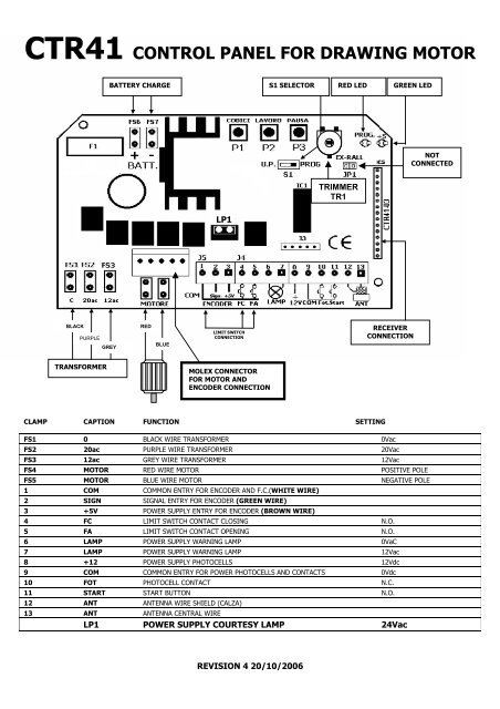
CTR41 CONTROL PANEL FOR DRAWING MOTOR<br />
BATTERY CHARGE S1 SELECTOR RED LED GREEN LED<br />
LP1<br />
TRIMMER<br />
TR1<br />
BLACK<br />
PURPLE<br />
RED<br />
LIMIT SWITCH<br />
CONNECTION<br />
RECEIVER<br />
CONNECTION<br />
GREY<br />
BLUE<br />
TRANSFORMER<br />
MOLEX CONNECTOR<br />
FOR MOTOR AND<br />
ENCODER CONNECTION<br />
CLAMP CAPTION FUNCTION SETTING<br />
FS1 0 BLACK WIRE TRANSFORMER 0Vac<br />
FS2 20ac PURPLE WIRE TRANSFORMER 20Vac<br />
FS3 12ac GREY WIRE TRANSFORMER 12Vac<br />
FS4 MOTOR RED WIRE MOTOR POSITIVE POLE<br />
FS5 MOTOR BLUE WIRE MOTOR NEGATIVE POLE<br />
1 COM COMMON ENTRY FOR ENCODER AND F.C.(WHITE WIRE)<br />
2 SIGN SIGNAL ENTRY FOR ENCODER (GREEN WIRE)<br />
3 +5V POWER SUPPLY ENTRY FOR ENCODER (BROWN WIRE)<br />
4 FC LIMIT SWITCH CONTACT CLOSING N.O.<br />
5 FA LIMIT SWITCH CONTACT OPENING N.O.<br />
6 LAMP POWER SUPPLY WARNING LAMP 0VaC<br />
7 LAMP POWER SUPPLY WARNING LAMP 12Vac<br />
8 +12 POWER SUPPLY PHOTOCELLS 12Vdc<br />
9 COM COMMON ENTRY FOR POWER PHOTOCELLS AND CONTACTS 0Vdc<br />
10 FOT PHOTOCELL CONTACT N.C.<br />
11 START START BUTTON N.O.<br />
12 ANT ANTENNA WIRE SHIELD (CALZA)<br />
13 ANT ANTENNA CENTRAL WIRE<br />
LP1 POWER SUPPLY COURTESY LAMP 24Vac<br />
REVISION 4 20/10/2006<br />
NOT<br />
CONNECTED
NB. THE J3 CLUTCH MUST NOT BE USED IN ANY CASE<br />
Factory settings<br />
The <strong>control</strong> unit has two functioning modes: the ENCODER MODE and the F.C. (closing limit switch) MODE.<br />
The unit is supplied as standard in the encoder mode making it possible to use the <strong>motor</strong> only with the encoder or with the encoder and F.C. (only<br />
when connected, otherwise it is necessary to leave the F.C. entries open).<br />
The F.C. mode makes functioning possible only with electromechanical F.C. (N.C.).<br />
To change modes, press down buttons P2 and P3 at the same time, until the red led flashes three times. Release the two buttons and then immediately<br />
select the functioning mode by pressing the buttons as follows:<br />
P1 <strong>for</strong> the ENCODER mode or P2 <strong>for</strong> the F.C. mode.<br />
NB. Allow the door to run its total run after each change.<br />
“Dead man” mode: during installation, verify that the “door” slides perfectly. To do this, move the S1 selector to the “U.P.” position and use the P1<br />
button to close and the P2 to open. NB. In the case of electromechanical F.C. functioning, check that the 2 polars do not touch the microswitch.<br />
Setting the door run: In the ENCODER mode, completely open the door, turn the S1 selector to the “PROG” position, press the P2 button until the<br />
red LED switches on and the <strong>motor</strong> is activated to close the door, then release the P2 button. When the door is completely closed, press the P2<br />
button again (during activation of the <strong>motor</strong>, absorption levels and working speed are calculated). If the electromechanical limit switch is assembled<br />
onto the <strong>motor</strong>, proceed with its adjustment using the two sliding polars.<br />
In the LIMIT SWITCH (F.C.) mode, completely close the door and adjust the closing limit switch. Completely open the door and adjust the opening<br />
limit switch. Turn the S1 selector to the “PROG” position and hold the P2 button until the door begins to close. At the end of the run, the <strong>motor</strong> will<br />
stop automatically and the run is set.<br />
Programming the closing approach mode (ONLY WITH ENCODER)<br />
This programming is necessary to establish the movement and approach mode of the door during the closing phase.<br />
Program 1- Switch off the power supply from the <strong>control</strong> unit. Press the P1 button whilst once again switching on the power and release the P1<br />
button after approximately 3 seconds. With this program the door will slowly move until it is completely closed. (standard factory setting)<br />
Program 2- Switch off the power supply from the <strong>control</strong> unit. Press the P2 button whilst once again switching on the power and release the P2<br />
button after approximately 3 seconds. With this program the door will slowly move until it is completely closed and will undergo further pressure from<br />
the <strong>motor</strong> provoking a slow-down in the chain, to be subsequently withdrawn.<br />
Step by step functioning: At each START command activated via the key selector or transmitter, the door will carry out the following cycle: OPEN –<br />
STOP – CLOSE – STOP.<br />
Automatic functioning: The door is opened at the first START command. Any START commands then made during the opening phase of the door<br />
will cause it to stop. At the end of the run, the door will close automatically after the pre-set PAUSE time. A START command effected during the<br />
PAUSE time will cause the door to close. A START command effected during the closing phase will cause the door to stop. Intervention of the<br />
photocell does not influence the opening phase whilst during the closing phase it causes stoppage and consequent reopening.<br />
Setting the remote <strong>control</strong> codes: Turn the S1 selector to the “PROG” position and press the P1 button once; this will cause the LED to flash. When<br />
the LED is properly switched on (no flashing), press the remote <strong>control</strong> button to be set <strong>for</strong> at least one second. Re-setting the codes: press the P1<br />
button until the LED switches off (approximately ten seconds).<br />
Setting pause time: Turn the S1 selector to the “PROG” position, press the P3 button until the LED is switched on (no flashing), release the button<br />
<strong>for</strong> a period of time equal to the desired pause time and then once again press the P3 button.<br />
Re-setting pause time: Turn the S1 selector to the “PROG” position, press the P3 button until the led switches off (approximately ten seconds). By<br />
resetting the pause time, the step by step functioning mode is automatically set.<br />
PROGRAMMIN G THE AMPEROMETRICAL THRESHOLD BY TRIMMER TR1<br />
This programming is to establish sensitivity in the presence of obstacles, both during the closing and the opening phases. The higher the value (e.g.<br />
7A), the more power the <strong>motor</strong> transmits to the door.<br />
NB. The presence of an obstacle during the opening phase will cause the door to stop and remain blocked until a new START<br />
command is effected.<br />
+<br />
-<br />
MANUAL SWITCHING ON OF THE COURTESY LAMP USING REMOTE CONTROL<br />
NB. This procedure is not obligatory <strong>for</strong> the functioning of the <strong>motor</strong>.<br />
It is possible to pilot the courtesy lamp placed in the <strong>motor</strong> using a two-channel transmitter. Turn the S1 selector to the PROG position. Press the P1<br />
button twice and wait till the red LED on the <strong>control</strong> unit is switched on (no flashing) and transmit the code to be set using the second button on the<br />
remote <strong>control</strong>. Once the code has been set, the second button of the transmitter can be used to switch on the courtesy lamp <strong>for</strong> a non-variable time of<br />
60 seconds.<br />
N.B. IN CASE OF MALFUNCTION, RESET THE CONTROL UNIT BY SWITCHING OFF THE POWER SUPPLY FOR A FEW SECONDS AND<br />
THEN RE-PROGRAMMING.<br />
For installation, comply with UNI 8612 and CEI standards regarding work safety.<br />
Always use a 16A differential switch and 0.030 A threshold.<br />
The product must be installed by qualified personnel in compliance with Law n. 46<br />
of 5th March 1990 and its subsequent modifications.<br />
REVISION 4 20/10/2006