Power Protection High Speed DC Circuit Breaker Type GERAPID ...
Power Protection High Speed DC Circuit Breaker Type GERAPID ...
Power Protection High Speed DC Circuit Breaker Type GERAPID ...

You also want an ePaper? Increase the reach of your titles
YUMPU automatically turns print PDFs into web optimized ePapers that Google loves.
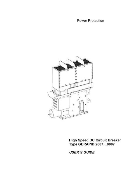
<strong>Power</strong> <strong>Protection</strong><br />
<strong>High</strong> <strong>Speed</strong> <strong>DC</strong> <strong>Circuit</strong> <strong>Breaker</strong><br />
<strong>Type</strong> <strong>GERAPID</strong> 2607…8007<br />
USER`S GUIDE
User’s Guide<br />
<strong>High</strong> <strong>Speed</strong> <strong>DC</strong> <strong>Circuit</strong> <strong>Breaker</strong><br />
<strong>Type</strong> Gerapid 2607...8007<br />
Arc Chute 1X2, 1X4, 2X2, 2X3, 2X4<br />
Table of Contens Page<br />
1. General 2<br />
1.1 Warnings 2<br />
1.2 Technical data 3<br />
1.3 Short description 5<br />
1.4 Structure and components 5<br />
2. Installation and operation 6<br />
2.1 Transportation 6<br />
2.2 Installation 6<br />
2.3 Setting the overload release 6<br />
2.4 Operation 7<br />
3. Inspection and maintenance 7<br />
3.1 General 7<br />
Tables inspection and maintenance required 8<br />
3.2 General visual and functional check 9<br />
3.3 Checking arc chute fittings and probe fittings 9<br />
3.4 Checking the arc chute 10<br />
3.5 Checking the contact area 10<br />
2<br />
(Protective walls, probes, contacts)<br />
4. <strong>Circuit</strong> diagrams 12<br />
5. Dimensional drawings 25<br />
6. Selection Form and Spares 36<br />
7. Eliminating operating troubles 39<br />
(Error detection)<br />
1. General<br />
1.1 Warnings<br />
<strong>GERAPID</strong> S47183e 0106 Design and specifications are subject to change without notice<br />
During operation, electrical equipment carries<br />
dangerous voltages. In addition, circuit breakers<br />
can emit hot, ionized gases when switching high<br />
currents, especially short circuit currents.<br />
Installing, commissioning, maintaining, changing<br />
or refitting this equipment must be carried out<br />
only by qualified and suitably trained specialist<br />
personnel and under strict observation of national<br />
and international applicable safety regulations.<br />
During their operation, circuit breakers must be<br />
equipped with appropriately fitted covers, e.g. in<br />
suitable enclosures or panel boards. Safety distances<br />
must be observed. Certain work must only<br />
be carried out by suitably trained service personnel.<br />
Non-compliance with these warnings may result<br />
in death, and/or severe physical damage and extensive<br />
damage to equipment.<br />
Prior to carrying out maintenance, inspection or<br />
checks, the circuit breaker must be open, the both<br />
terminals must be grounded, the circuit breaker<br />
must be switched off and the control plug removed.<br />
During operation, i.e. when the circuit breaker is<br />
closed, manual activation is not permissible.<br />
Manual activation must only be used for maintenance<br />
purposes.<br />
The circuit breaker is equipped with quickly<br />
moving parts. There is a high risk of injury. Do not<br />
touch the circuit breaker while it is being switched<br />
ON or OFF.<br />
The control circuits are equipped with capacitors<br />
which may by charged with dangerous voltages.<br />
Work on this section must be carried out carefully.
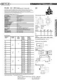
1.2 Technical data<br />
<strong>Breaker</strong> type Gerapid 2607 Gerapid 4207<br />
Arc chute type 1x2 1x4 2x2 2x3 2x4 1x2 1x4 2x2 2x3 2x4<br />
Rated service current (I Ne) A 2.600 4.200<br />
Rated voltage (U Ne) V 1.000 2.000 2.000 3.000 3.600 1.000 2.000 2.000 3.000 3.600<br />
Short circuit breaking capacity (I cc max.) 1)<br />
kA 244 50 100 50 52 244 50 100 50 52<br />
Peak of the short-circuit current (I ss)<br />
acc. to EN 50123-2 kA 100 50 100 50 40 100 50 100 50 40<br />
Rated short-circuit current (I Nss) 2)<br />
acc. to EN 50123-2 kA 70 30 71 35 28 70 30 71 35 28<br />
Rated short.circuit current (I cs)<br />
aacc. to IEC 947-2 kA 80 40 65 40 40 60 40 65 40 40<br />
Switching transient kV 2 4 4 5,6 7 2 4 4 5,6 7<br />
Rated track time constant (TNc) kA/ms 31,5 31,5 31,5 31,5 31,5 31,5 31,5 31,5 31,5 31,5<br />
Short time current 120 min. A 3.150 5.000<br />
2 min. A 5.200 8.500<br />
20 sec. A 7.800 12.600<br />
Rated insulation voltage(U Nm) V 1.000 2.000 2.000 3.000 4.000 1.000 2.000 2.000 3.000 4.000<br />
Rated impulse withstand voltage (U Ni) kV 12 18 18 30 30 12 18 18 30 30<br />
1,2/50 µs, gem.prEN 50124-1:1997<br />
Mechanical endurance 0ps. 20.000 3)<br />
20.000 3)<br />
Total weight approx. kg 120 120 160 160 160 120 120 160 160 160<br />
1) max. value acc. to customer specifications<br />
2) <strong>High</strong>er values on request (it depends on different conditions)<br />
3) With regular maintenance up to 100.000 ops.<br />
Table 1a: Technical data, type Gerapid 2607, 4207<br />
4) Test only by customer order<br />
<strong>Breaker</strong> type Gerapid 6007 Gerapid 8007<br />
Arc chute type 1x2 1x4 2x2 2x3 2x4 1x2 2x2 2x3<br />
Rated service current (I Ne) A 6.000 8.000<br />
Rated voltage (U Ne) V 1.000 2.000 2.000 3.000 3.600 1.000 2.000 3.000<br />
Short circuit breaking capacity (I cc max.) 1)<br />
kA 200 50 80 50 4) 200 50 4)<br />
Peak of the short-circuit current (I ss)<br />
acc. to EN 50123-2 kA 70 50 80 50 4) 71 4) 4)<br />
Rated short-circuit current (I Nss) 2)<br />
acc. to EN 50123-2 kA 50 35 56 35 4) 50 4) 4)<br />
Rated short.circuit current (I cs)<br />
acc. to IEC 947-2 kA 80 40 65 40 4) 60 50 4)<br />
Switching transient kV 2 4 4 5,6 7 2 4 5,6<br />
Rated track time constant (T Nc) kA/ms 31,5 31,5 31,5 31,5 31,5 31,5 31,5 31,5<br />
Short time current 120 min. A 7.200 9.600<br />
2 min. A 12.000 16.000<br />
20 sec. A 18.000 24.000<br />
Rated insulation voltage(U Nm) V 1.000 2.000 2.000 3.000 4.000 1.000 2.000 3.000<br />
Rated impulse withstand voltage (U Ni) kV 12 18 18 30 30 12 18 30<br />
1,2/50 µs, gem.prEN 50124-1:1997<br />
Mechanical endurance 0ps. 20.000 3)<br />
20.000 3)<br />
Total weight approx. ca. kg 150 150 190 190 190 190 210 210<br />
1) max. value acc. to customer specifications<br />
3) With regular maintenance up to 100.000 ops.<br />
Table 1b: Technical data, type Gerapid 6007, 8007<br />
2) <strong>High</strong>er values on request (it depends on different conditions)<br />
4) Test only by customer order<br />
<strong>GERAPID</strong> S47183e 0106 Design and specifications are subject to change without notice 3
Auxiliary current connector 1x12-pole AC 400V, 20A<br />
4x15-pole AC 250V, 8A<br />
Activating magnet 1)<br />
Rated voltage Uc AC 48V…230V and <strong>DC</strong> 48V…220V<br />
Operating range 0.8...1.1 Uc<br />
4<br />
<strong>Power</strong> consumption Gerapid 2607 / 4207 1750W / 2000W<br />
<strong>Power</strong> consumption Gerapid 6007 / 8007 2600W / 2600W<br />
Minimal command signal time 100ms<br />
min.interval between two ON-operations approx. 8s without C ; approx. 14s with C<br />
Internal power supply 1)<br />
Input: Voltage range <strong>DC</strong> 33...75V<br />
for Gerapid 2607…8007 Output: Voltage range <strong>DC</strong> 24V (+/-5%)<br />
or<br />
Current 6A permanent<br />
Input: Voltage range <strong>DC</strong> 50...150V<br />
Output: Voltage range <strong>DC</strong> 24V (+/-5%)<br />
Current 6A permanent<br />
or<br />
Input: Voltage range AC 115...290V, <strong>DC</strong> 125...353V<br />
Output: Voltage range <strong>DC</strong> 24V (+/-5%)<br />
Current 3A permanent, 5A/100ms<br />
External power supply with plug and socket unit <strong>DC</strong> 24V (+/-5%)<br />
Aux. contact HS 1…HS 10, Rated operational voltage Ue/AC 230V<br />
ks- und arc chute- indication Rated operational current Ie/AC-15 1A<br />
a-trip 1)<br />
Rated operational current Ie/AC-12 (Ith) 10A<br />
Rated operational voltage Ue/<strong>DC</strong> 110V<br />
Rated operational current Ie/<strong>DC</strong>-13 0,5A<br />
Contact duty (min. value) <strong>DC</strong> 10V/2 mA<br />
Rated voltage Uc 24V<br />
(Shunt trip) Operating range: OFF 21.6V…26.4V<br />
r-release 1)<br />
<strong>Power</strong> consumption approx. 100W<br />
Rated voltage Uc 24V<br />
(Zero voltage release) Operating range: OFF < 3V<br />
Operating range: ON 24V (+/-10%)<br />
ed-trip 1)<br />
<strong>Power</strong> consumption approx. 11W<br />
Energie source: Capacity 2000µF<br />
Charging voltage 300V<br />
Switching interval max. 1/min.<br />
Firingsignal 2) level / duration 6…24V / 100…1000ms<br />
1) Standard ambient conditions acc. to EN 123-1 Attachement B. For meeting outside of this standard range, please call back.<br />
2) Hints to avoid misoperations and defects at the control boards: for the connecting cables of the firing signal it's necessary to make sure,<br />
by adequate methods, that particularly no glitch like the limit of firing voltage (6V) or signals with very short duration (< 3msec) appears<br />
Table 2a: Technical data of auxiliary circuits<br />
Components Technical datas of control circuits<br />
Us / In<br />
SU-Control ON-push-button -S1 <strong>DC</strong> 24V / approx. 10mA<br />
a-trip push-button-S2 <strong>DC</strong> 24V / approx. 4A<br />
r-release push-button -S2 ( -X2 :6 / :7) <strong>DC</strong> 24V / approx. 10mA<br />
push-button -S2 ( -X2 :8 / :9 ) <strong>DC</strong> 24V / approx. 450mA<br />
ed-trip(R = 4Ohm) push-button -S3 <strong>DC</strong> 300V / 750A / 3ms<br />
ed-trip with capacity unit Connection "Firing signal" ( -X2 :10 / :11 ) <strong>DC</strong> 6V…24V / approx.20mA<br />
Table 2b: Control circuits ( directional values to rate the components )<br />
<strong>GERAPID</strong> S47183e 0106 Design and specifications are subject to change without notice
1.3 Short deskription<br />
<strong>GERAPID</strong> high speed <strong>DC</strong> circuit breakers are single-pole<br />
circuit breakers designed for use in railway<br />
propulsion-power distribution systems with operating<br />
currents up to 8000A and operating voltages up to<br />
3600V <strong>DC</strong>. They have a very high interruption capacity<br />
combined with a current limiting characteristic.<br />
Closing of the circuit breaker is performed through a<br />
high-power activating magnet. During inspections,<br />
opening and closing may be carried out by means of<br />
a hand lever, which can be mounted onto the armature<br />
of the activating magnet.<br />
Overload tripping is achieved directly via a short circuit<br />
trip or, depending on the rate of current rise, by<br />
an external current-rise release with an internal capacitor<br />
trip (ed - trip available as an accessory). Indirect<br />
remote tripping can be achieved by means of a<br />
shunt trip (a-trip) or a zero voltage release (rrelease).<br />
The arc chute works on the basis of an asbestosfree<br />
arc splitting principle.<br />
A wide variety of accessories and spares is available<br />
for maintenance, repair, or possible extension.<br />
1.4 Structure and components<br />
<strong>Type</strong> <strong>GERAPID</strong> high speed <strong>DC</strong> circuit breakers<br />
have a compact and enclosed construction. They<br />
are IP 00 protected. All parts are mounted on thickwalled,<br />
non-breakable and fireproof insulation panels,<br />
whose large covers protect the breaker’s<br />
mechanism from damage. Transparent plastic side<br />
covers are available as an accessory to protect<br />
metal connecting elements on the panel.<br />
<strong>GERAPID</strong> breakers are equipped with a two-stage<br />
contact system. The main contacts are coated with a<br />
silver composite material, the arcing contacts are<br />
made from copper and can be easily replaced. The<br />
flexible contact is linked to the connection by means<br />
of very tight braids.<br />
An attachment set is used to mount the various arcsplitting<br />
systems for different operating voltages to<br />
the breakers. The arc chutes consist of a highly durable,<br />
arc-proof material, into which the arc plates<br />
have been integrated. The arc plates split the arc<br />
into partial arcs and increase the arcing voltage by<br />
multiplying the anode and cathode voltage drop. Because<br />
of their high heat capacity, the plates and arc<br />
chute walls absorb a large amount of the arc’s energy.<br />
The overload trip design uses a release magnet with<br />
twin magnets, optimizing the twin magnetic field<br />
principle. This technology ensures an equally fast<br />
tripping in both current directions.<br />
The magnetic system does not require an auxiliary<br />
voltage. The system consists of the holding circuit,<br />
the flexible armature and the tripping circuit. The<br />
holding magnet and the tripping magnet are both<br />
excited by main current.<br />
Until the static overload release’s response threshold<br />
has been reached, the flexible armature is held<br />
in position by the holding circuit’s magnetic field and<br />
the counter spring. If the main current exceeds the<br />
set static response threshold, the tripping circuit’s<br />
power takes over and pulls the flexible armature<br />
down suddenly. During this operation, the armature<br />
trips the release lever. The main latch and contacts<br />
are opened immediately. The response threshold<br />
can be easily adjusted by turning the adjustment nut<br />
with a SW6 hexagon wrench. In combination with<br />
the transparent side cover accessory, a fixed<br />
mounted insulated knob is available (accessory).<br />
To detect high short circuit currents early and to record<br />
leakage currents in long peripheral sections (for<br />
railway equipment), whose final values are lower<br />
than the highest operating currents, protective relays<br />
for monitoring a current increase should be installed.<br />
If a fault occurs, a release signal can be passed on<br />
to the capacitor release, which causes the breaker<br />
to open rapidly (opening delay
The activation magnet is mounted at the front of the<br />
breaker and is equipped with a grounded casing.<br />
The drive includes a self-interrupt control circuit (SUcontrol).<br />
This circuit enables a short activation with a<br />
minimum command duration of approximately<br />
300ms, causes the voltage applied to the magnet to<br />
be switched off after approximately 400ms and prevents,<br />
during continuous operation, repeated activation<br />
(anti-pumping) due to an existing short circuit. In<br />
addition, the switch-in mechanism is electrically<br />
blocked for approximately 10s after activation. This<br />
prevents premature activation following a short circuit.<br />
The breaker is equipped with up to ten isolated form<br />
C auxiliary contacts (1 NO/NC each). The auxiliary<br />
contacts are activated by the movable main contact.<br />
They are wired to 15-pin control plugs. As an accessory<br />
the circuit breaker can be equipped with auxiliary<br />
switches for indication of short circuit tripping<br />
and for the presence of the arc chute.<br />
6<br />
a<br />
Fig. 0 Points for handling the breaker<br />
b<br />
2. Installation and operation<br />
2.1 Transportation<br />
<strong>GERAPID</strong> S47183e 0106 Design and specifications are subject to change without notice<br />
• The circuit breaker must always be transported<br />
to the installation site properly and fully packed.<br />
The packaging protects the device against<br />
damage and dust; it should only be removed<br />
prior to installation.<br />
• If the packaging is damaged, the breaker and<br />
the arc chute must be inspected for damage.<br />
Ensure that all packaging materials have been<br />
carefully removed prior to breaker installation.<br />
• For handling the unpacked breaker use the robust<br />
points a and b at the drive and the lower<br />
terminal [Fig. 0].<br />
• Listen, that the basement isolation of the unpacked<br />
breaker during handling will not be<br />
damaged (for example don’t push the breaker<br />
back and forth at rough surface.)<br />
2.2 Installation<br />
The breakers, as delivered, are IP00 protected.<br />
They must be installed in a dry, preferably dust-free<br />
room. They must not be subjected to strong vibrations.<br />
The lower and upper connections must be<br />
connected directly to the main cables and busbars.<br />
The breaker must only be used in an upright operation<br />
position with the arc chute in place and<br />
fully secured. After installation, both the arc chute<br />
and special threaded joints must be checked for<br />
tightness.<br />
The safety distances as shown in the dimensional<br />
drawings must be maintained to grounded or insulated<br />
parts. Suitable measures must be taken to<br />
protect personnel from arcs.<br />
Strong, external magnetic fields, caused by improperly<br />
located supply conductors or tray fields from<br />
other devices, can lead to a shift of the trip setting<br />
thresholds. This may result in premature tripping, or<br />
no tripping at al, during low-level short circuit current<br />
events. This has to be accounted for when installing<br />
and operating the device with shielding added if appropriate.<br />
The control wires must be connected as shown in<br />
the schematic circuit diagram [Fig. 8].<br />
The protective grounding wire must be connected at<br />
the marked contact.
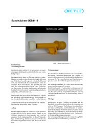
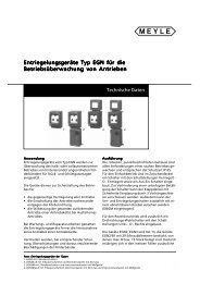
2.3 Setting the overload release<br />
The adjustment of the static overload release [Fig.1]<br />
within a specific adjustment range is made by turning<br />
the regulating screw 1. This procedure requires<br />
an SW6 hexagon wrench 2. The adjustment must<br />
only be carried out after the breaker has been disconnected<br />
from the main circuit and has been<br />
grounded. Turning the adjustment screw clockwise<br />
increased the trip threshold, turning the screw<br />
counter-clockwise decreased the tripping thres hold.<br />
Adjustment is performed by aligning both the arrow<br />
and the marking line to one line 3.<br />
Fig. 1 Setting the overload release<br />
SW 6<br />
2.4 Operation<br />
In accordance with its type, the breaker has been<br />
designed for the current and voltage listed in<br />
Table 1.<br />
During continuous operation, it must be loaded with<br />
its rated operating current at maximum. Load currents<br />
in excess of breaker nameplate rating are allowable<br />
for brief periods. Refer to the short time currents<br />
listed in Table 1. Do not exceed the rated operating<br />
voltage shown on the breaker nameplate.<br />
The drive and auxiliary trip function within the specified<br />
control voltage range. The auxiliary trips must<br />
be loaded with the values listed in Table 2a at<br />
maximum.<br />
Plugging or removing the auxiliary current connectors<br />
are only allowed at zero potential, no voltage<br />
(-X2 :1/:2) (-X3 :4/:5).<br />
3. Inspection and maintenance<br />
Prior to carrying out maintenance, inspection or<br />
checks on the circuit breaker, the breaker must<br />
be open, the connections on both sides must be<br />
grounded, the circuit breaker must be switched<br />
off and the control plugs removed. Noncompliance<br />
with these warnings can result in<br />
death, severe physical damage and extensive<br />
damage to equipment.<br />
Don’t finger into the closed breaker.<br />
Metric tools are needed for all screws.<br />
3.1 General<br />
Regular inspection and maintenance must be carried<br />
out to ensure the proper functioning of the<br />
breaker and in order to achieve a long working life.<br />
The intervals at which inspections must be carried<br />
out may be determined by evaluating the breaker’s<br />
duty cycle. Table 3a provides an overview of checks<br />
to be carried out and lists the appropriate inspection<br />
intervals. Table 3b provides indicators for maintenance<br />
work.<br />
A thorough check of the latch mechanism and the<br />
current path should only be carried out by service<br />
engineers or technicians trained and qualified by GE<br />
Industrial Systems. Changing the arc contacts and<br />
arc probes, see technical information:<br />
“<strong>High</strong> <strong>Speed</strong> <strong>DC</strong> <strong>Circuit</strong> <strong>Breaker</strong> <strong>Type</strong> <strong>GERAPID</strong>,<br />
HINTS + INSTRUCTIONS ”.<br />
<strong>GERAPID</strong> S47183e 0106 Design and specifications are subject to change without notice 7
<strong>Type</strong> of inspection Intervals of inspection Work of inspection<br />
General visual and functional<br />
check<br />
Checks:<br />
• Contacts<br />
• Arc probes<br />
• Protective walls<br />
• Arc chute (LBK)<br />
Check breaker and tripping<br />
mechanism. To be carried out<br />
by trained specialist.<br />
Check arc probes and arc<br />
chute screw connections<br />
Table 3a: Inspections required<br />
8<br />
Recommendation: every 6 months<br />
At least once a year<br />
• After high short circuit openings<br />
(>25kA)<br />
• at frequent operations with overload-and/or<br />
rated current<br />
At least once a year<br />
After 5.000 mech. operations<br />
At least once every 4 years<br />
After each job carried out in the<br />
• contacts<br />
• probes<br />
• arc chute<br />
At least once every 6 months<br />
Work to be carried out required<br />
• Changing arc chute (LBK)<br />
• Adjustment of latch mechanism (only carried<br />
out by service engineers)<br />
• Exchange parts (only carried out by service engineers<br />
or technicians trained)<br />
• Changing pre-arcing contact and probes.<br />
Recommendation: changing completely!<br />
(Carried out by technicians trained)<br />
• Changing protective walls<br />
Table 3b: Maintenance required<br />
<strong>GERAPID</strong> S47183e 0106 Design and specifications are subject to change without notice<br />
Remove dirt, check drive and<br />
trips for correct operations<br />
Check for wear and deposits<br />
Check proper operation,<br />
setting values and flexible braid<br />
Check for tight fitting<br />
As required by the results of the inspection<br />
As required by the results of the inspection,<br />
or to be done latest after<br />
- 100 overload operations or<br />
- 300 loadbreak operations at rated current
3.2 General visual and functional check<br />
• Switch the breaker ON and OFF several times.<br />
The contacts must close after the ON command,<br />
the contacts must open following the<br />
OFF command via the shunt trip and the zero<br />
voltage release.<br />
The breaker mechanism must not appear<br />
sluggish nor must ON/OFF be unduly delayed.<br />
• Pay attention to the warnings at page 2 !<br />
Check breaker for presence of dirt, and, if applicable,<br />
remove all dirt with a dry cloth. No<br />
particularly high signs of abrasion (rough<br />
chips) should be seen anywhere. In order to<br />
check the latch mechanism, the breaker can<br />
be opened and closed with a hand lever. Fig. 2<br />
shows the correct use of the lever.<br />
• A thorough check of the latch mechanism and<br />
the current path should only be carried out by<br />
service engineers or technicians trained and<br />
qualified by GE Consumer & Industrial.<br />
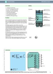
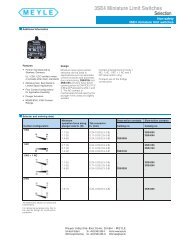
3.3 Checking the arc chute fittings and the<br />
probe fittings<br />
Pay attention to the warnings at page 2 !<br />
[Fig.3] Tighten front- and backside of the arc probe<br />
screw connections 3 and 3a with a torque of 10Nm<br />
and arc chute connections 4 with a torque of 5Nm.<br />
Ensure that the screws are in good condition, that<br />
there is no damage to the thread or the tool insertion<br />
point and that the surface is free from rust. If<br />
this is not the case, they must be replaced.<br />
The arc probe screw connections 3 must be secured<br />
by means of lock washer, the arc chute<br />
screw connections 4 by means of flat washer.<br />
This check must be carried out prior to commissioning<br />
and after every maintenance.<br />
Fig. 2 Manual ON/OFF.<br />
Fig. 3 Checking chute and probe fittings<br />
<strong>GERAPID</strong> S47183e 0106 Design and specifications are subject to change without notice 9<br />
4<br />
3<br />
3a
3.4 Checking the arc chute<br />
follow the instructions of points A) … D):<br />
A) General hint<br />
Pay attention to the warnings at page 2 !<br />
B) Remove the arc chute<br />
[Fig. 4] Loosen the clamping screws 3 and<br />
4 (SW 5 hexagon wrench) and take out the<br />
arch chute 1 from the adapter 2.<br />
C) Check the arc chute<br />
[Fig. 5] Check the chute’s interior, as far<br />
as possible, for deposits and check the<br />
general condition of the insulation material<br />
and the arc horns for wear.<br />
During this inspection check:<br />
• whether there are many copper pearls on<br />
the chute’s plates 1 (that could partially link<br />
the plates)<br />
• whether the arc horns’ cross section 2 is<br />
heavily reduced<br />
• whether the splitting plates 3 are heavily<br />
burned<br />
• whether the chute’s internal insulation is<br />
heavily damaged.<br />
D) Install the arc chute<br />
[Fig. 4] Put in arc chute 1 into adapter 2.<br />
Tighten front- and backside of the arc<br />
probe screw connections 3 (including lock<br />
washer) with a torque of 10 Nm. Tighten<br />
front- and backside of the arc chute connections<br />
4 (including flat washer) with a<br />
torque of 5 Nm.<br />
3.5 Checking the contact area<br />
(Protective walls, probes, contacts)<br />
follow the instructions of points a) … i):<br />
a) General hint<br />
Pay attention to the warnings at page 2 !<br />
b) Remove the arc chute<br />
[Fig. 4] Loosen the clamping screws 3 and<br />
4 (SW 5 hexagon wrench) and take out the<br />
arc chute 1 from the adapter 2.<br />
10<br />
<strong>GERAPID</strong> S47183e 0106 Design and specifications are subject to change without notice<br />
c) Remove the arc chute adapter<br />
[Fig. 6] For dismantling the arc-chute<br />
adapter loosen and pull out the four upright<br />
screws 1 (SW5).<br />
Pay attention that no screws and discs<br />
fall into the breaker!<br />
Lift off the two parings of adapter 2. Pull<br />
out the two protective walls 3.<br />
[Fig. 7]:<br />
d) Check the protective walls<br />
The material erosion rate on the protective<br />
walls 5 must not exceed 1mm in any place.<br />
e) Check the pre-arcing probes<br />
The arc contacts should not be burned<br />
below 1/3 of the total cross section in any<br />
place. Pay particular attention to the area<br />
around probe bend 3 and firing point of<br />
pre-arcing contact 2.<br />
f) Check the pre-arcing contacts<br />
Wear on pre-arcing contact 1 should<br />
amount to no more than 2mm; the limiting<br />
value is 3mm! If it is burned down more, it<br />
must be replaced.<br />
g) Check the main contacts<br />
The main contacts 4 should not show any<br />
particular signs of material erosion, since,<br />
in the case of ordinary short circuits or<br />
overload and operating current deactivation,<br />
the arc is ignited between the prearcing<br />
contacts. Ignition can take place on<br />
the main contacts only with excessively<br />
worn and old pre-arcing contacts or very<br />
high short circuit currents. The wear should<br />
not exceed an area of 1mm.<br />
h) Install the arc chute adapter<br />
[Fig. 6] Install the two protective walls 3<br />
(new one if necessary). Install the two<br />
parings of adapter 2 and tighten it (hand<br />
operated).<br />
i) Install the arc chute<br />
[Fig. 4] Put in arc chute 1 into adapter 2.<br />
Tighten front- and backside of the arc<br />
probe screw connections 3 (including lock<br />
washer) with a torque of 10 Nm. Tighten<br />
front- and backside of the arc chute connections<br />
4 (including flat washer) with a<br />
torque of 5 Nm.
Fig. 4 Arc chute and probe fittings<br />
Fig. 5 Inspecting the arc chute<br />
1<br />
2<br />
3<br />
4<br />
Fig. 6 Arc chute adapter, protective walls<br />
Fig. 7 Checking the contacts, probes and the<br />
protective walls<br />
<strong>GERAPID</strong> S47183e 0106 Design and specifications are subject to change without notice 11<br />
2<br />
1<br />
3
4. <strong>Circuit</strong> diagrams<br />
Activating magnet<br />
(Solenoid drive)<br />
a-trip or r-release<br />
ed-trip<br />
ks-trip<br />
HS 1...HS 10<br />
ks-indication<br />
arc chute-indication<br />
Description Designation<br />
X2 1.Connector: Auxiliary- and control circuits<br />
X3 2.Connector: Auxiliary- and control circuits<br />
X4 3.Connector: Auxiliary contacts HS1...HS5<br />
X5 4.Connector: Auxiliary contacts HS6...HS10<br />
X6 5.Connector: Current measure system SEL<br />
X10 Control board: <strong>Power</strong> supply unit<br />
X11 Control board: Voltage supply <strong>DC</strong> 24V external<br />
X12 Control board: Self interrupt control (SU)<br />
X13 Control board: Shunt trip (a-trip)<br />
X14, X15 Control board: Zero voltage trip (r-release) (X15: r-release mod.)<br />
X16 Control board: ed charge- and trip component<br />
X17 Control board: Current measure system SEL<br />
Fig. 8 Connecting plug allocation<br />
12<br />
<strong>GERAPID</strong> S47183e 0106 Design and specifications are subject to change without notice
Basic connections definitions<br />
The power circuits are not shown in the wiring diagrams<br />
due to clarity. The control circuit is presented<br />
as a typical circuit diagram and is a combination<br />
of numbered basic diagrams for drives trips<br />
and indicators. The number of the complete diagram<br />
can be derived by using the key numbers of<br />
the basic plan.<br />
Key position 1 / 2 3 4 5 6 7 8<br />
<strong>Type</strong><br />
Aux. voltage<br />
Tripping coil<br />
Drive<br />
Tripping dev.<br />
Indicat. switch<br />
Aux. contacts<br />
Current-meas.<br />
system<br />
Example: complete diagram No.<br />
Key position 36 / 1 1 20 10 01 2 S<br />
Gerapid<br />
<strong>Power</strong> supply<br />
ed-trip coil<br />
Drive+SU<br />
Shunt trip<br />
ks-Indication<br />
5 Aux.switches<br />
SEL<br />
Key position<br />
Key Key Designation<br />
position<br />
<strong>Type</strong><br />
number<br />
1 36 Gerapid<br />
Auxiliary voltage<br />
2 1 AC/<strong>DC</strong> Converter<br />
2 <strong>DC</strong> 24V external supply<br />
Tripping coil<br />
3 0 Without ed-trip coil<br />
1 With ed-trip coil<br />
Drive<br />
2 With ed-trip coil and<br />
internal capacitor unit<br />
4 20 Solenoid drive with<br />
Self cut-off control<br />
Tripping device<br />
5 00 Without trip<br />
10 With shunt trip<br />
20 With zero voltage release<br />
Indication device<br />
6 00 Without indication<br />
01 ks-indication<br />
02 Arc chute indication<br />
03 ks+arc chute indication<br />
Auxiliary contacts<br />
7 1 3 auxiliary switches<br />
2 5 auxiliary switches<br />
3 10 auxiliary switches<br />
Current-measurement system<br />
8 S With SEL<br />
Indication of components<br />
Q1 <strong>Circuit</strong> breaker<br />
S1 Push button „ON“<br />
S2 Push button „OFF“"<br />
Cut off control unit:<br />
K1 Closing relay<br />
K2 Closing block relay<br />
Shunt trip, zero voltage release:<br />
K1 Closing STOP relay<br />
HS11 Auxiliary contact<br />
ed-trip with internal capacitor unit:<br />
K1 Voltage monitoring relay<br />
<strong>GERAPID</strong> S47183e 0106 Design and specifications are subject to change without notice 13
14<br />
Q1:X4<br />
15<br />
14<br />
13<br />
12<br />
11<br />
10<br />
9<br />
8<br />
7<br />
6<br />
5<br />
4<br />
3<br />
2<br />
1<br />
3)S3<br />
2)<br />
2)S2<br />
1)S2<br />
S2<br />
1)<br />
S1<br />
S2<br />
3)S3<br />
S1<br />
PE<br />
<strong>Power</strong> supply<br />
S2<br />
Q1:X2<br />
12<br />
11<br />
10<br />
9<br />
8<br />
7<br />
6<br />
5<br />
4<br />
3<br />
2<br />
1<br />
<strong>Power</strong> supply<br />
<strong>Power</strong> supply<br />
Q1:X5<br />
15<br />
14<br />
13<br />
12<br />
11<br />
10<br />
9<br />
8<br />
7<br />
6<br />
5<br />
4<br />
3<br />
2<br />
1<br />
Q1:X3<br />
15<br />
14<br />
13<br />
12<br />
11<br />
10<br />
9<br />
8<br />
7<br />
6<br />
5<br />
4<br />
3<br />
2<br />
1<br />
6) S4<br />
6) S4<br />
Position of auxiliary switches is shown in the “ON” position of maincontacts<br />
1) with shunt trip<br />
2) with zero voltage release<br />
3) with ed trip<br />
4) with ks tripping indicator switch<br />
5) with arc chute mounted indicator switch<br />
6) with current measurement unit (polarity of the output signal<br />
shown by current flow from top to bottom connection of the<br />
breaker)<br />
Fig. 9 Connecting plug termination (Indicating switches, 3 auxiliary switches)<br />
<strong>GERAPID</strong> S47183e 0106 Design and specifications are subject to change without notice<br />
5)<br />
5)<br />
4)<br />
4)<br />
3)<br />
3)<br />
Q1:X6<br />
15<br />
14<br />
13<br />
12<br />
11<br />
10<br />
9<br />
8<br />
7<br />
6<br />
5<br />
4<br />
3<br />
2<br />
1<br />
-<br />
6)<br />
+ 6)<br />
-<br />
6)<br />
+<br />
6)<br />
+/- 10V<br />
+/- 20mA<br />
-6)<br />
+ 6)<br />
4...20mA
3)<br />
PE<br />
<strong>Power</strong> Supply<br />
S2<br />
S3<br />
1) S2<br />
2) S2<br />
3)<br />
2)S2<br />
1)S2<br />
S1<br />
S1<br />
S3<br />
Q1:X4<br />
15<br />
14<br />
13<br />
12<br />
11<br />
10<br />
9<br />
8<br />
7<br />
6<br />
5<br />
4<br />
3<br />
2<br />
1<br />
Q1:X2<br />
12<br />
11<br />
10<br />
9<br />
8<br />
7<br />
6<br />
5<br />
4<br />
3<br />
2<br />
1<br />
<strong>Power</strong> supply<br />
<strong>Power</strong> supply<br />
Q1:X5<br />
15<br />
14<br />
13<br />
12<br />
11<br />
10<br />
9<br />
8<br />
7<br />
6<br />
5<br />
4<br />
3<br />
2<br />
1<br />
Q1:X3<br />
15<br />
14<br />
13<br />
12<br />
11<br />
10<br />
9<br />
8<br />
7<br />
6<br />
5<br />
4<br />
3<br />
2<br />
1<br />
6)S4<br />
6)S4<br />
Position of auxiliary switches is shown in the “ON” position of maincontacts<br />
1) with shunt trip<br />
2) with zero voltage release<br />
3) with ed trip<br />
4) with ks tripping indicator switch<br />
5) with arc chute mounted indicator switch<br />
6) with current measurement unit (polarity of the output signal<br />
shown by current flow from top to bottom connection of the<br />
breaker)<br />
Fig. 10 Connecting plug termination (Indicating switches, 5 auxiliary switches)<br />
<strong>GERAPID</strong> S47183e 0106 Design and specifications are subject to change without notice<br />
5)<br />
5)<br />
4)<br />
4)<br />
3)<br />
3)<br />
Q1:X6<br />
15<br />
14<br />
13<br />
12<br />
11<br />
10<br />
9<br />
8<br />
7<br />
6<br />
5<br />
4<br />
3<br />
2<br />
1<br />
-<br />
6)<br />
+ 6)<br />
-<br />
6)<br />
+<br />
6)<br />
+/- 10V<br />
+/- 20mA<br />
-<br />
6)<br />
+ 6)<br />
4...20mA<br />
15
16<br />
3)S3<br />
2)<br />
2)S2<br />
1)S2<br />
PE<br />
<strong>Power</strong> supply<br />
S2<br />
S2<br />
1)<br />
S1<br />
S2<br />
3)S3<br />
S1<br />
Q1:X4<br />
15<br />
14<br />
13<br />
12<br />
11<br />
10<br />
9<br />
8<br />
7<br />
6<br />
5<br />
4<br />
3<br />
2<br />
1<br />
Q1:X2<br />
12<br />
11<br />
10<br />
9<br />
8<br />
7<br />
6<br />
5<br />
4<br />
3<br />
2<br />
1<br />
Q1:X5<br />
15<br />
14<br />
13<br />
12<br />
11<br />
10<br />
9<br />
8<br />
7<br />
6<br />
5<br />
4<br />
3<br />
2<br />
1<br />
<strong>Power</strong> supply<br />
<strong>Power</strong> supply<br />
Q1:X3<br />
15<br />
14<br />
13<br />
12<br />
11<br />
10<br />
9<br />
8<br />
7<br />
6<br />
5<br />
4<br />
3<br />
2<br />
1<br />
6) S4<br />
6) S4<br />
Position of auxiliary switches is shown in the “ON” position of maincontacts<br />
1) with shunt trip<br />
2) with zero voltage release<br />
3) with ed trip<br />
4) with ks tripping indicator switch<br />
5) with arc camber mounted indicator switch<br />
6) with current measurement unit (polarity of the output signal<br />
shown by current flow from top to bottom connection of the<br />
breaker)<br />
Fig. 11 Connecting plug termination (Indicating switches, 10 auxiliary switches)<br />
<strong>GERAPID</strong> S47183e 0106 Design and specifications are subject to change without notice<br />
5)<br />
5)<br />
4)<br />
4)<br />
3)<br />
3)<br />
Q1:X6<br />
15<br />
14<br />
13<br />
12<br />
11<br />
10<br />
9<br />
8<br />
7<br />
6<br />
5<br />
4<br />
3<br />
2<br />
1<br />
-<br />
6)<br />
+ 6)<br />
-<br />
6)<br />
+<br />
6)<br />
+/- 10V<br />
+/- 20mA<br />
-6)<br />
+ 6)<br />
4...20mA
+ / ~<br />
-S3<br />
-S1<br />
ON Command<br />
-X2<br />
-X2<br />
-X2<br />
-X2<br />
-X10, 11<br />
-X10, 11<br />
:1<br />
<strong>Power</strong> supply<br />
of the drive<br />
N / ~<br />
:2<br />
:5<br />
:4<br />
:9<br />
:6<br />
3<br />
4<br />
9<br />
8<br />
10<br />
7<br />
-X12<br />
36/ . . XX .. .. . .<br />
Fig. 12 Activating magnet with SU control-circuit<br />
-<br />
~<br />
~<br />
+<br />
ON Signal circuit<br />
<strong>Power</strong> <strong>Circuit</strong><br />
<strong>GERAPID</strong> S47183e 0106 Design and specifications are subject to change without notice<br />
2<br />
Key No. 20<br />
-Q1 Drive<br />
1<br />
Closing Control<br />
Closing Block Release<br />
5 6<br />
Closing<br />
Stop Signal<br />
17
18<br />
-S2<br />
-HS11<br />
3<br />
4<br />
X2<br />
X2<br />
:6<br />
:7<br />
X13<br />
Fig. 13 a-trip (shunt trip)<br />
4<br />
3<br />
2<br />
1<br />
-K1<br />
36/ . . .. XX .. . .<br />
Closing Stop Signal<br />
5 6<br />
-K1<br />
A1 A2<br />
Key No. 00 Without auxiliary trip<br />
Key No. 10 with shunt trip<br />
<strong>GERAPID</strong> S47183e 0106 Design and specifications are subject to change without notice<br />
8<br />
7<br />
9<br />
10<br />
-X10, 11<br />
-X10, 11<br />
:9<br />
24 V<br />
C1<br />
C2<br />
:7<br />
+<br />
-
-<br />
24 V<br />
+<br />
X14<br />
7<br />
8<br />
:7<br />
:6<br />
-X2 -X2<br />
-K2<br />
-S2<br />
Fig. 14 r-release (zero voltage release)<br />
3 4<br />
A1<br />
A2<br />
A1 A2<br />
-K1 -K2<br />
-D1<br />
9 10<br />
36/ . . .. XX .. . .<br />
U<<br />
-K1<br />
<strong>GERAPID</strong> S47183e 0106 Design and specifications are subject to change without notice<br />
5<br />
6<br />
2<br />
1<br />
Closing Stop Signal<br />
-X2 :8<br />
-X2 :9<br />
Key No. 20 with zero voltage release<br />
-S2<br />
19
20<br />
Voltage converter<br />
33..353V <strong>DC</strong> 115..290V AC<br />
~ / +<br />
-X10<br />
-X3<br />
36/ X . .. .. .. . .<br />
Input 33....75V <strong>DC</strong> (R3)<br />
50..150V <strong>DC</strong> (R4)<br />
125..353V <strong>DC</strong> (R5)<br />
115..290V AC (R5)<br />
Output 24V <strong>DC</strong> +/- 5%<br />
-X3<br />
4<br />
1<br />
N / -<br />
3<br />
5<br />
10<br />
9<br />
8<br />
7<br />
+24V<br />
6 -24V<br />
Closing Stop<br />
Voltage converter<br />
external 24V <strong>DC</strong> +/-5%<br />
+ 24 V<br />
Fig. 15 <strong>Power</strong> supply unit internal ( AC/<strong>DC</strong> ) and external ( <strong>DC</strong> 24V +/- 5% )<br />
-X3<br />
-X3<br />
<strong>GERAPID</strong> S47183e 0106 Design and specifications are subject to change without notice<br />
4<br />
5<br />
- 24 V<br />
1<br />
3<br />
-X11<br />
10<br />
9<br />
8<br />
7<br />
6<br />
Closing<br />
Stop<br />
Key No. 1 Voltage converter 33..75V <strong>DC</strong>; 50..150V <strong>DC</strong>; 125..353V <strong>DC</strong>; 115..290V AC<br />
Key No. 2 Voltage converter external 24V +/- 5%
-X10, 11<br />
<strong>Power</strong> supply<br />
24V <strong>DC</strong><br />
-X10, 11<br />
-X3<br />
Signal C<br />
charged<br />
-X3<br />
Q1 ed<br />
:6<br />
:8<br />
-<br />
:6<br />
:7<br />
+<br />
Closing<br />
Stop Signal<br />
+<br />
-X2:10<br />
Firing Signal<br />
6..24V<br />
-<br />
-X2:11<br />
3<br />
4<br />
1<br />
2<br />
9<br />
10<br />
5<br />
6<br />
11<br />
12<br />
-X16<br />
Contactors<br />
36/ . X .. .. .. . .<br />
Firing circuit<br />
Capacity and firing thyristor<br />
Key No. 2 with ed-trip and capacity unit<br />
Fig. 16 ed-trip (electrodynamic-trip) with capacitor unit<br />
Pulse <strong>Circuit</strong><br />
Voltage Control<br />
Firing signal<br />
transforming<br />
and control<br />
<strong>GERAPID</strong> S47183e 0106 Design and specifications are subject to change without notice<br />
Insulating Transformer<br />
Charging control<br />
21
22<br />
Impulsecapacity<br />
300V 2000µF<br />
36/ . X .. .. .. . .<br />
-X2<br />
Key No. 0 without ed-trip<br />
Key No. 1 with simple ed-trip<br />
Fig. 17 ed-trip (electrodynamic-trip)<br />
-X2<br />
:10<br />
:11<br />
-S3<br />
-Q1<br />
ed<br />
<strong>GERAPID</strong> S47183e 0106 Design and specifications are subject to change without notice
-X3<br />
-X3<br />
:8<br />
:9<br />
36/ . . .. .. xx . . 36/ . . .. .. xx . .<br />
-X3<br />
-X3<br />
36/ . . .. .. xx . .<br />
Key No. 00 without indication Key No. 02 with arc chute-indication<br />
Key No. 01 with ks-indication<br />
:8<br />
:9<br />
-X3<br />
-X3<br />
Key No. 03 with ks- und arc chute- indication<br />
Fig. 18 ks- und arc chute- indication<br />
:12<br />
:13<br />
-X3<br />
-X3<br />
<strong>GERAPID</strong> S47183e 0106 Design and specifications are subject to change without notice<br />
:12<br />
:13<br />
23
1)<br />
2)<br />
3)<br />
1) max. 500 Ω<br />
24<br />
<strong>DC</strong> 24V<br />
2) max. 500 Ω<br />
36/ . . .. .. .. . X<br />
Functioncontrol<br />
3) min. 300kΩ<br />
Key No. „S“ with SEL<br />
Signalprocessing<br />
Voltageconstanter<br />
<strong>DC</strong> 24V<br />
Fig. 19 Current measurement system type SEL 06-1...12-4<br />
<strong>GERAPID</strong> S47183e 0106 Design and specifications are subject to change without notice
5. Dimensional drawings<br />
Warnings<br />
During operation all metallic parts of the breaker except housing and driving magnet may carry<br />
dangerous voltages.<br />
Insulation covers are available as accessories.<br />
For installation of the breaker into cubicles top and side openings are to provide in order to reduce<br />
internal pressure rise in case of clearing short circuit.<br />
All openings respectively free areas on the top of the cubical shall be not less than 50%.<br />
<strong>GERAPID</strong> S47183e 0106 Design and specifications are subject to change without notice<br />
25
26<br />
<strong>Type</strong> Arc chute Main- additional Deflector Safety distances / Insulated plates Safety distances / Earthed plates<br />
Gerapid Connection isolation<br />
action E A B C D A B C D<br />
2607 / 4207 1x2 all 10 700 150 150 120 1000 300 300 300<br />
1x3 all 1) 1) 1) 1) 1) - - - -<br />
1x4 all 150 700 150 150 120 1350 450 450 200<br />
2x2 all 80 1000 300 300 300 1350 450 450 300<br />
2x3 all 80 1000 180 180 180 - - - -<br />
2x4 W / W Plate 150 1000 180 180 180 - - - -<br />
2x4 W / W Sidewalls 150 1000 180 180 180 - - - -<br />
2x4 SEL / W Pan 150 1000 180 180 180 - - - -<br />
6007 1x2 S / S Heat sink 10 1000 300 300 180 - - - -<br />
1x3 1) 1) 1) 1) 1) 1) 1) - - - -<br />
1x4 S / S Heat sink 150 1000 300 300 180 - - - -<br />
2x2 S / S Heat sink 80 1000 180 180 180 - - - -<br />
2x3 S / S Heat sink 80 1000 180 180 180 - - - -<br />
2x4 1) 1) 1) 1) 1) 1) 1) - - - -<br />
8007 1x2 S / S Heat sink 10 1000 300 300 180 - - - -<br />
1x3 1) 1) 1) 1) 1) 1) 1) - - - -<br />
1x4 1) 1) 1) 1) 1) 1) 1) - - - -<br />
2) 2x2 S / S Heat sink 80 1000 180 180 180 - - - -<br />
2) 2x3 S / S Heat sink 80 1000 180 180 300 - - - -<br />
2x4 1) 1) 1) 1) 1) 1) 1) - - - -<br />
1) will be checked by customers order 2) acc. IEC 947-2 / ks-setting
Fig. 20 Gerapid 2607- 6007, arc chute 1X (Dimensions in mm)<br />
Pay attention to warnings page 25! Legend and safety distances see page 26<br />
<strong>GERAPID</strong> S47183e 0106 Design and specifications are subject to change without notice<br />
27
Fig. 21 Gerapid 2607- 6007, arc chute 2X (Dimensions in mm)<br />
Pay attention to warnings page 25! Legend and safety distances see page 26<br />
28<br />
<strong>GERAPID</strong> S47183e 0106 Design and specifications are subject to change without notice
Fig. 22 Gerapid 8007, arc chute 1X (Dimensions in mm)<br />
Pay attention to warnings page 25! Legend and safety distances see page 26<br />
<strong>GERAPID</strong> S47183e 0106 Design and specifications are subject to change without notice<br />
29
Fig. 23 Gerapid 8007, arc chute 2X (Dimensions in mm)<br />
Pay attention to warnings page 25! Legend and safety distances see page 26<br />
30<br />
<strong>GERAPID</strong> S47183e 0106 Design and specifications are subject to change without notice
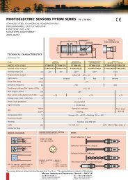
Fig. 24 Gerapid 2607 / 4207 connections horizontal (Dimensions in mm)<br />
It’s able to combine connections horizontal and vertical, dimensions are corresponding.<br />
<strong>GERAPID</strong> S47183e 0106 Design and specifications are subject to change without notice<br />
31
Fig. 25 Gerapid 2607 / 4207 connections vertical (Dimensions in mm)<br />
It’s able to combine connections horizontal and vertical, dimensions are corresponding.<br />
32<br />
<strong>GERAPID</strong> S47183e 0106 Design and specifications are subject to change without notice
Fig. 26 Gerapid 6007, connections vertical only (Dimensions in mm)<br />
<strong>GERAPID</strong> S47183e 0106 Design and specifications are subject to change without notice<br />
33
Fig. 27 Gerapid 8007, connections vertical only (Dimensions in mm)<br />
34<br />
<strong>GERAPID</strong> S47183e 0106 Design and specifications are subject to change without notice
Forced tripping device<br />
Fig. 28 Bottom view<br />
Fig. 29 Length of stroke<br />
Front<br />
<strong>GERAPID</strong> S47183e 0106 Design and specifications are subject to change without notice<br />
35
6. Selection-Form and Spares<br />
Selection-Form<br />
• Ampere Ratings<br />
• Operational Voltage<br />
• Tripping unit<br />
36<br />
Ampere Ratings (A)<br />
<strong>Type</strong> <strong>GERAPID</strong> IEC 947-2 EN 50123-2 ANSI C37.14<br />
2607 2600 2600 2600<br />
4207 4200 4200 4150<br />
6007 6000 6000 5000<br />
8007 8000 8000 6000<br />
Arc Chute<br />
2607 4207 6007 8007<br />
<strong>DC</strong> 800V 1) 1x2 1x2 1x2 1x2<br />
<strong>DC</strong> 1000V 1x2 1x2 1x2 1x2<br />
<strong>DC</strong> 1200V 2) 1x2 1x2 1x2 1x2<br />
<strong>DC</strong> 2000V 1x4 1x4 1x4 -<br />
<strong>DC</strong> 2000V 2x2 2x2 2x2 2x2<br />
<strong>DC</strong> 3000V 2x3 2x3 2x3 -<br />
<strong>DC</strong> 4000V 2x4 2x4 - -<br />
<strong>DC</strong> 4000V EF4-12 EF4-12 - -<br />
1) Version for ANSI C37.14<br />
2) Version for ANSI C37.14 (on request)<br />
Release value (kA)<br />
2607 4207 6007 8007<br />
1…3 - - -<br />
1,5…5 1.5…5 - -<br />
3…7 3…7 3...7 3…7<br />
5…10 5…10 5...10 5…10<br />
7…12 7…12 7...12 7…12<br />
8…16 8...18 8…18<br />
12...20 12…24<br />
fi Price of the tripping unit includes 6 calibration points.<br />
fi Add. 6, 12, or 18 calibration points available (extra prices).<br />
<strong>GERAPID</strong> S47183e 0106 Design and specifications are subject to change without notice
• <strong>Power</strong> Supply Control Voltage<br />
<strong>DC</strong> 24V <strong>DC</strong> 33-75V <strong>DC</strong> 50-150V <strong>DC</strong> 125-353V /<br />
AC 115-290V<br />
• Voltage for<br />
Activating Magnet<br />
2607 4207 6007 8007<br />
<strong>DC</strong> 48V <br />
<strong>DC</strong> 60V <br />
<strong>DC</strong> 110V <br />
<strong>DC</strong> 125V <br />
<strong>DC</strong> 220V <br />
AC 120V <br />
AC 230V <br />
fi Other voltages on request<br />
• Auxiliary Contacts 3 5 10<br />
• Main Rear Terminals<br />
Upper Terminals horizontal vertical<br />
Lower Terminals horizontal vertical<br />
fi 6007 / 8007 only vertical/vertical terminals<br />
fi with Integrated Current Measurement <strong>Type</strong> SEL upper terminal vertical only<br />
• Accessories<br />
ks-indication (short-circuit indication, short-time indication)<br />
a-trip (shunt trip) 3)<br />
r-release (zero voltage release, shunt trip function integrated) 3)<br />
ed -trip unit „simple“ (electrical-dynamic ed -coil only)<br />
ed -trip unit with „C“ (ed -coil, capacitors, electronic unit)<br />
Automatically OFF by safety mechanism (for draw-out unit)<br />
Position indicator (optics „O – I“)<br />
Insulated side walls for Gerapid 2607 / 4207<br />
Hand lever (for maintenance only)<br />
Arc-chute indication (indication „arc chute is put on“)<br />
Integrated Current Measurement <strong>Type</strong> SEL 4) +/- 6kA, basic version …35°C<br />
Integrated Current Measurement <strong>Type</strong> SEL 4) +/-12kA, basic version …35°C<br />
Integrated Current Measurement <strong>Type</strong> SEL 4) +/- 6kA, special design…55°C<br />
Integrated Current Measurement <strong>Type</strong> SEL 4) +/-12kA, special design…55°C<br />
Mod. Plug and Socked for Control <strong>Circuit</strong>s (on request)<br />
3) 4)<br />
alternative a-trip or r-release for Gerapid 2607/4207<br />
• Nameplate Standard Special (ANSI C37.14)<br />
<strong>GERAPID</strong> S47183e 0106 Design and specifications are subject to change without notice<br />
37
38<br />
Spares<br />
Name of the item for type Z-No.<br />
1 Pre-arcing contact (assembling from 11/2003) 1)<br />
2607 - 8007<br />
128 122 R02 2)<br />
Pre-arcing contact (assembling up to 10/2003) 1)<br />
Back probe (at the fixed contact) 1)<br />
Front probe (at the moveably contact) 1)<br />
Protective walls, right side / left side 1)<br />
2607 - 8007 128 121 2)<br />
2607 - 8007, LBK 1X 128 521 R01<br />
2607 - 8007, LBK 2X 128 521 R02<br />
2607 - 6007, LBK 1X 128 525 R01<br />
8007, LBK 1X 128 525 R02<br />
2607 - 6007, LBK 2X 128 525 R03<br />
8007, LBK 2X 128 525 R04<br />
2607 - 8007, LBK 1X 128 515 R01 / 128 516 R01<br />
2607 - 8007, LBK 2X 128 515 R02 / 128 516 R02<br />
2 Main contact, fixed 2607 - 6007 128 110 R01<br />
8007 128 110 R02<br />
3 Main contact, moveably 2607 128 108 R01<br />
4207 128 108 R02<br />
6007 128 108 R03<br />
8007 128 108 R04<br />
4 Activating magnet 2607 - 8007 128 070 "R xy" 3)<br />
5 Arc chute for type 2607 - 8007 1X2 128 550 R01<br />
1X3 128 550 R02<br />
1X4 128 550 R03<br />
2X2 128 550 R11<br />
2X3 128 550 R12<br />
2X4 128 550 R13<br />
6 Shunt trip (standard unit) 2607 - 8007 128 300 R01<br />
Shunt trip (extern voltage) 2607 - 8007 128 300 R02<br />
arc chute (2-winding coil) 2607 - 8007 128 300 R03<br />
7 Cero voltage release 2607 - 8007 128 320<br />
8 Auxiliary switch HS (1 change over contact) 2607 - 8007 174 349<br />
9 NEKO (capacitor battery for ed) 2607 - 8007 128 750 R01<br />
10 <strong>Power</strong> supply unit (voltage transformer) 2607 - 8007<br />
- extern <strong>DC</strong>24V +/-5% 128 730 R1<br />
- <strong>DC</strong> 33…75V 128 730 R3<br />
- <strong>DC</strong> 50…150V 128 730 R4<br />
- <strong>DC</strong> 125…353V or AC 115…290V 128 730 R5<br />
11 Control board for self interrupt control (SU) 2607 - 8007 128 700<br />
12 Control board for shunt trip <strong>DC</strong> 24V 2607 - 8007 128 710 R01<br />
13 Control board for zero voltage trip <strong>DC</strong> 24V 2607 - 8007 128 710 R02<br />
14 Control board for current measure system SEL 2607 - 4207 128 785<br />
1)<br />
Recommendation: change the pre-arcing contact, the probes<br />
and the protective walls always complete!<br />
3) „R xy“ = specify type and voltage<br />
(look at page 37, table „Voltage for Activating Magnet“)<br />
2) Help for identification<br />
Pre-arcing contact 128 122 R02 Pre-arcing contact 128 121<br />
<strong>GERAPID</strong> S47183e 0106 Design and specifications are subject to change without notice
7. Eliminating operating troubles (error detection)<br />
Switching ON the breaker not possible<br />
„Activating magnet doesn't work electrical but (after making sure it's not alive!) contacts<br />
works mechanical with the hand lever."<br />
• Control voltage Us not available or to low?<br />
Check, if voltage delivered by the power supply is not available or to low<br />
(measure points :4/:5)<br />
• Voltage loss to large at the coil of the activating magnet?<br />
Measure or calculate control voltage Uc of the magnet.<br />
• Control cable interrupted or not correct connected ?<br />
• If control voltage o.k. change circuit board.<br />
• Note the polarity of the power supply.<br />
Check measure points :1/:2 at plug X2 and measure points :4/:5 at plug X3.<br />
• Check if error in customised auxiliary control circuit.<br />
• Activating magnet faulty? (call service department)<br />
• a-trip control board faulty?<br />
• Check “C” (capacitors) of ed-trip.<br />
„Activating magnet works electrical but contacts doesn’t close“<br />
• If available, check r-release<br />
- Control voltage available?<br />
- Feeding and connection o.k.?<br />
- r-release coil faulty?<br />
• Check, if positive tripping is wrong adjusted.<br />
• Faulty mechanic? (call service department)<br />
Switching OFF the breaker not possible<br />
„a-trip don't release“<br />
• Control voltage available ?<br />
• Control plugs o.k.?<br />
• Control cables o.k.?<br />
• a-trip faulty? (call service department)<br />
• Auxiliary switch HS 11 wrong adjusted?<br />
• Faulty mechanic ? (call service department)<br />
„r-release don't release“<br />
• Faulty mechanic ? (call service department)<br />
„ed-trip unit don't release“<br />
• Capacitors control board faulty? (change it)<br />
• Interface of line measuring device faulty?<br />
Faulty control boards<br />
• Change the complete control board<br />
<strong>GERAPID</strong> S47183e 0106 Design and specifications are subject to change without notice<br />
39
Meyer Industrie-Electronic GmbH – MEYLE<br />
Carl-Bosch-Straße 8<br />
49525 Lengerich/Germany<br />
40<br />
Tel.: +49 54 81-9385-0<br />
Fax: +49 54 81-9385-12<br />
Internet: www.meyle.de<br />
E-Mail: sales@meyle.de<br />
<strong>GERAPID</strong> S47183e 0106 Design and specifications are subject to change without notice