Lecture 10: Bolometers - Leiden Observatory
Lecture 10: Bolometers - Leiden Observatory
Lecture 10: Bolometers - Leiden Observatory

You also want an ePaper? Increase the reach of your titles
YUMPU automatically turns print PDFs into web optimized ePapers that Google loves.
Detection of Light: <strong>Lecture</strong> <strong>10</strong><br />
Detection of Light<br />
<strong>Lecture</strong> <strong>10</strong>: <strong>Bolometers</strong><br />
Matthew Kenworthy // <strong>Leiden</strong> <strong>Observatory</strong> // 2012
Overview of Course Topics<br />
•<br />
•<br />
•<br />
•<br />
•<br />
Detection of Light: <strong>Lecture</strong> <strong>10</strong><br />
Before solid state<br />
Solid State Physics<br />
Photodiodes and variants<br />
Detector Arrays<br />
Artifacts, multiplexers, readout schemes<br />
• CCDs<br />
• <strong>Bolometers</strong><br />
•<br />
Heterodyne Receivers
Three Basic Types of Detectors<br />
• Photon detectors<br />
Respond directly to individual photons - releases bound charge carriers. Used from<br />
X-ray to infrared.<br />
Examples: photoconductors, photodiodes, photoemissive detectors, photographic<br />
plates<br />
• Thermal detectors<br />
Absorb photons and thermalize their energy - modulates electrical current. Used<br />
mainly in IR and sub-mm detectors.<br />
Examples: bolometers<br />
• Coherent receivers<br />
Respond to electrical field strength and preserve phase information (but need a<br />
reference phase “local oscillator”). Mainly used in the sub-mm and radio<br />
regime.<br />
Examples: heterodyne receivers<br />
Detection of Light: <strong>Lecture</strong> <strong>10</strong>
Detection of Light: <strong>Lecture</strong> <strong>10</strong><br />
<strong>Bolometers</strong>: History<br />
The night sky has a large thermal emission at <strong>10</strong> microns<br />
SOLUTION: rapid beam switching to remove the sky background<br />
The father of astronomical bolometers is Frank Low<br />
Invented the Ge:Ga bolometer in 1961
A milestone in the history of bolometers<br />
Detection of Light: <strong>Lecture</strong> <strong>10</strong><br />
Many references to John C. Mather (Applied Optics 21, 1125, 1982)<br />
The Nobel prize in Physics 2006 (with George Smoot)<br />
PI for Far Infra Red Absolute Spectrophotometer (FIRAS) on COBE
Detection of Light: <strong>Lecture</strong> <strong>10</strong><br />
State of the Art bolometers<br />
http://www.apex-telescope.org/bolometer/laboca/technical/<br />
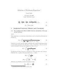
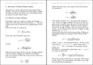
LABOCA – the multichannel<br />
bolometer array for<br />
APEX operating in the 870<br />
μm (345 GHz) atmospheric<br />
window.<br />
The signal photons are<br />
absorbed by a thin metal film<br />
cooled to about 280 mK.<br />
The array consists of 295<br />
channels in 9 concentric<br />
hexagons.<br />
The array is under-sampled,<br />
thus special mapping<br />
techniques must be used.
Detection of Light: <strong>Lecture</strong> <strong>10</strong><br />
State of the Art bolometers<br />
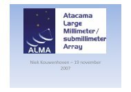
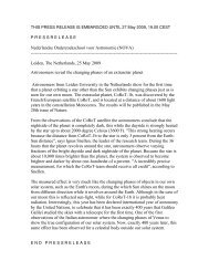
Herschel/PACS bolometer:<br />
a cut-out of the 64x32 pixel bolometer array<br />
assembly.<br />
4x2 monolithic matrices of 16x16 pixels are<br />
tiled together to form the short-wave focal<br />
plane array.<br />
The 0.3 K multiplexers are bonded to the<br />
back of the sub-arrays. Ribbon cables lead<br />
to the 3K buffer electronics.
Detection of Light: <strong>Lecture</strong> <strong>10</strong><br />
Basic Principle
Basic Operation of a Bolometer<br />
T0<br />
Wavelengths: infrared to sub-mm<br />
Detection of Light: <strong>Lecture</strong> <strong>10</strong><br />
Incoming photon’s energy.... E = hc<br />
...is absorbed as HEAT and increases the<br />
temperature of the material<br />
hv to kT
Detection of Light: <strong>Lecture</strong> <strong>10</strong><br />
Definitions<br />
Thermal conductance (Watts per Kelvin):<br />
G<br />
Thermal heat capacity (Joules per Kelvin): C<br />
Temperature Coefficient of Resistance (1/Kelvin): ↵
Steady State Operation of a Bolometer<br />
Detection of Light: <strong>Lecture</strong> <strong>10</strong><br />
T0<br />
G = P0<br />
T0 + T1<br />
Heat sink Bolometer<br />
T1<br />
Thermal link<br />
Incoming photon power flux increases Bolometer<br />
from equilibrium temperature T0 to T0 + . T1<br />
A thermal link with thermal conductance G transfers power to<br />
a heat sink of temperature T0<br />
P0<br />
P0
Time Response of a Bolometer<br />
Detection of Light: <strong>Lecture</strong> <strong>10</strong><br />
T0<br />
Adding an astronomical source represented as a time<br />
varying component:<br />
Heat sink Bolometer<br />
Thermal link<br />
⌘PV (t) = dQ<br />
dt<br />
= C dT1<br />
dt<br />
Where ⌘ is quantum efficiency, Q is thermal energy,<br />
and C = dQ/dT1 is the heat capacity [J/K]<br />
PV (t)
Bolometer Thermal Time constant<br />
The total power absorbed by the detector is:<br />
T1(t) = PT<br />
G<br />
Detection of Light: <strong>Lecture</strong> <strong>10</strong><br />
PT (t) =P0 + PV (t) =GT1 + C dT1<br />
dt<br />
Now we turn on a signal so that: t0<br />
The time constant is T = C/G<br />
For t>>⇥T the temperature T1 ⇠ (P0 + P1)<br />
...so if you measure the temperature then you can know the power
Physical Layout of Semiconductor Bolometer<br />
Detection of Light: <strong>Lecture</strong> <strong>10</strong><br />
A chip of doped silicon or germanium acts<br />
BOTH as bolometer detector<br />
AND thermometer<br />
High input impedance amplifier measures the voltage<br />
Voltage depends on resistance<br />
Resistance depends on temperature
Temperature Coefficient of Resistance<br />
Detection of Light: <strong>Lecture</strong> <strong>10</strong><br />
We want to talk about how the temperature of the<br />
bolometer changes its electrical resistance, so we talk<br />
about the temperature coefficient of resistance:<br />
So, R depends on the temperature:<br />
↵ = ↵(T )= 1<br />
R<br />
dR<br />
dT<br />
The sign of the Temperature Coefficient leads to very<br />
different behaviour for a bolometer.<br />
...where and are constants<br />
R0<br />
Units of K 1<br />
B
Detection of Light: <strong>Lecture</strong> <strong>10</strong><br />
The Bolometer Readout Circuit<br />
Johnson noise is NOT the<br />
limiting factor for bolometers<br />
so we don’t worry about setting<br />
high R<br />
We can use this circuit to measure the bolometer resistance R.<br />
Vbias<br />
RL<br />
R Vout<br />
We assume so that<br />
the current through the bolometer is<br />
limited by RL<br />
RL >> R
R vs T for intrinsic semiconductor<br />
<strong>Bolometers</strong> measure the resistance R via Vout<br />
Vbias<br />
RL<br />
R Vout<br />
Detection of Light: <strong>Lecture</strong> <strong>10</strong><br />
Rd =<br />
...where the number of charge carriers is:<br />
So, R depends on the temperature:<br />
From previous lectures, we know that:<br />
1 l<br />
wd<br />
n0 =2<br />
= 1<br />
qn0µn<br />
✓ 2m ⇤ nkT<br />
h 2<br />
l<br />
wd<br />
◆ 3/2<br />
R = R0T 3/2 e B/T<br />
...where and are constants<br />
R0<br />
e (Ec EF )/kT<br />
B
Temperature kept low for good resistivity properties<br />
<strong>Bolometers</strong> suffer from the same fundamental noise mechanisms as photoconductors<br />
Detection of Light: <strong>Lecture</strong> <strong>10</strong><br />
PLUS the noise arising from thermal fluctuations<br />
Keep temperature of the bolometer very low<br />
T
Detection of Light: <strong>Lecture</strong> <strong>10</strong><br />
Approximations for the temperature<br />
coefficient of resistance<br />
The electrical resistance for hopping can be described by:<br />
( /T )✏<br />
R = R0e<br />
...where ⇡ 1/2 and is a characteristic temperature ⇡ 4 <strong>10</strong>K<br />
The temperature coefficient of resistance is defined as:<br />
(T )= 1<br />
R<br />
dR<br />
dT =<br />
1<br />
R0e ( /T )1/2<br />
d<br />
dT<br />
(R0e ( /T )1/2<br />
) ⇡ 1<br />
2<br />
(T )= 1<br />
R<br />
Substituting the hopping resistance into the above equation we get:<br />
ALTERNATIVELY<br />
T> R = R0<br />
For one gets empirically that<br />
However, in both cases the point is that:<br />
✓ T<br />
T0<br />
= f(T )<br />
◆ A<br />
and so<br />
✓<br />
T 3<br />
dR<br />
dT<br />
◆ 1/2<br />
(T ) ⇡ A<br />
T<br />
...with A = 4
Detection of Light: <strong>Lecture</strong> 11<br />
Electrothermal feedback<br />
For ALL semiconductors, we know that the higher the temperature,<br />
the lower the resistivity (more charge carriers generated) :<br />
⌧T = C<br />
G<br />
⌧E
Detection of Light: <strong>Lecture</strong> <strong>10</strong><br />
Electrical Responsivity<br />
Let dR, dT and dV be the changes in resistance, temperature and voltage<br />
across the bolometer, caused by the absorbed power dP.<br />
So, we get:<br />
dV = IdR= I[ (T )RdT]= (T )V dT=<br />
with Rieke p.244:<br />
SE = dV<br />
dP =<br />
dT =<br />
(T )V<br />
G (T )PI<br />
(T )V dP<br />
G (T )PI<br />
dP<br />
G (T )PI<br />
The responsivity is completely determined by the electrical properties of<br />
the detector (so this is also called electrical responsivity)
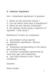
Measuring Electrical Responsivity<br />
The detector properties G and (T ) are not always known and you need to<br />
determine them by measurement<br />
You measure the “load curve” of I-V<br />
by adjusting the load resistor RL<br />
Vbias<br />
RL<br />
R Vout<br />
Detection of Light: <strong>Lecture</strong> <strong>10</strong><br />
Note that the local slope is<br />
different from “the resistance”<br />
R because of the non-linearity<br />
of the load curve.<br />
Slope of the load curve is: Z = dV<br />
dI<br />
Nominal operating point<br />
The Load Curve
etermining responsivity at V0<br />
The resistance at the point V0 is:<br />
Z = R<br />
The local slope is:<br />
If you now rewrite Z as follows.....<br />
Z = dV<br />
dI<br />
Detection of Light: <strong>Lecture</strong> <strong>10</strong><br />
d(log P )<br />
d(log R)<br />
H +1<br />
H 1<br />
= R d(log V )<br />
d(log I)<br />
= 1<br />
I 2<br />
R0 = V0/I0<br />
(dI/dV )0 =1/Z0<br />
= R<br />
dP<br />
dR<br />
so H = Z + R<br />
Z R<br />
d(log P )<br />
d(log R) +1<br />
d(log P )<br />
d(log R) 1<br />
...we can now find an expression for d(log P)/d (log R):<br />
= 1<br />
I 2<br />
G = P<br />
T<br />
dP<br />
dT<br />
dT<br />
dR =<br />
(T )= 1<br />
R<br />
G<br />
(T )I 2 R<br />
dR<br />
dT<br />
= G<br />
(T )P<br />
= H<br />
P = V ⇥ I = I 2 R<br />
Z and R can be measured, so we can get<br />
H, then back to determine G and a(T)
SE =<br />
G = (T )HP<br />
Detection of Light: <strong>Lecture</strong> <strong>10</strong><br />
Different timescales<br />
...back to the electrical responsivity:<br />
(T )V<br />
G (T )PI<br />
=<br />
(T )V<br />
(T )HP (T )P =<br />
On the other hand, if α(T) is known G = α(T)HP permits the determination of the thermal conductance G from<br />
the load curve.<br />
⇥E =<br />
V (Z R)<br />
2RP<br />
...and the electrical time constant:<br />
C<br />
G (T )P<br />
= V<br />
2P<br />
T = C<br />
G<br />
= C<br />
G G<br />
H<br />
✓<br />
Z<br />
R 1<br />
◆<br />
= ⇥T<br />
1 1<br />
H<br />
V<br />
P (H 1) =<br />
= 1<br />
2I<br />
=<br />
✓<br />
Z<br />
R 1<br />
◆<br />
⇥T<br />
1 Z R<br />
Z+R<br />
P<br />
= ⇥T<br />
V<br />
⇣ Z+R<br />
Z R<br />
⌘<br />
Z + R<br />
2R<br />
1<br />
=
Detector responsivity from electrical responsivity<br />
Detection of Light: <strong>Lecture</strong> <strong>10</strong><br />
Mather (1982) has a derivation that includes a correction<br />
factor of (RL + R)/(RL + Z)<br />
So that:<br />
E = T<br />
✓ Z + R<br />
2R<br />
◆✓ RL + R<br />
RL + Z<br />
This equation can be used to determine the heat capacity C = T G<br />
of the bolometer in terms of (which can be measured from S(f) )<br />
⌧E<br />
So, SE is electrical responsivity, but now we can derive the responsivity to<br />
incoming radiation (where only a fraction ⌘ of the incoming energy is<br />
absorbed) :<br />
◆<br />
SR = SE = 2I<br />
✓<br />
Z<br />
R 1<br />
◆
Responsivity compared to photodetectors<br />
Photoconductor<br />
Sphotoconductor = ⇥qG<br />
hc<br />
Photodiode<br />
Sphotodiode = ⇥q<br />
hc<br />
Bolometer<br />
Sbolometer = 2I<br />
The bolometer responsivity is independent of the wavelength<br />
(assuming QE is independent of )<br />
Detection of Light: <strong>Lecture</strong> <strong>10</strong><br />
✓<br />
Z<br />
R 1<br />
◆<br />
⌘
Two sources of Bolometer Heating<br />
T0<br />
Detection of Light: <strong>Lecture</strong> 11<br />
Incoming photon flux produces<br />
AND<br />
Electrical heating from the current<br />
sensing in the thermometer<br />
PV (t)<br />
PI<br />
PI = I 2 (Remember that ⇥ R(T ) in the thermometer)
T0<br />
Detection of Light: <strong>Lecture</strong> 11<br />
Two time constants<br />
Heat flowing out of the bolometer<br />
through the thermal link gives rise to<br />
AND<br />
The electrical power changes with an<br />
electrical time constant<br />
⌧E =<br />
⌧T = C<br />
G<br />
C<br />
G ↵(T )PI
Detection of Light: <strong>Lecture</strong> <strong>10</strong><br />
Noise and NEP<br />
There is Johnson noise, characterised by the noise voltage<br />
VJ =< I 2 J > 1/2 R<br />
CASE 1: if VJ is added to the bias voltage, the dissipated power P<br />
increases and R decreases (because of the negative resistance coefficient)<br />
so the voltage across the detector decreases<br />
CASE 2: if VJ opposes the bias voltage, the dissipated power P decreases<br />
and R increases, so net voltage across the detector still decreases<br />
In both cases, the detector response opposes the ohmic voltage change<br />
resulting from Johnson noise (negative electrothermal feedback)<br />
=<br />
4kT f<br />
R<br />
(T ) < 0
Johnson noise:<br />
Thermal noise:<br />
Photon noise:<br />
TOTAL NEP NOISE:<br />
Detection of Light: <strong>Lecture</strong> <strong>10</strong><br />
The total NEP<br />
NEPJ ⇡<br />
NEPT = (4kT 2 G) 1/2<br />
NEPphoton = hc<br />
⇥<br />
GT 2 for (T ) ⇡ T 3/2<br />
GT 3/2 for (T ) ⇡ T 1<br />
....due to fluctuations in the thermal motions of charge carriers<br />
(random currents due to Brownian motion)<br />
due to fluctuations of entropy across the thermal link that<br />
connects the detector and the heat sink.<br />
✓ 2⇤ ◆ 1/2<br />
...due to fluctuations in the photon flux<br />
NOTE: <strong>Bolometers</strong> DO NOT HAVE G-R noise<br />
(remember: no particle pairs created/destroyed)<br />
NEP = p (NEP 2 photon + NEP 2 + NEP 2 J + ...)