EPOS2 50/5 Hardware Reference (englisch, PDF ... - Maxon Motor ag
EPOS2 50/5 Hardware Reference (englisch, PDF ... - Maxon Motor ag
EPOS2 50/5 Hardware Reference (englisch, PDF ... - Maxon Motor ag

You also want an ePaper? Increase the reach of your titles
YUMPU automatically turns print PDFs into web optimized ePapers that Google loves.
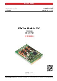
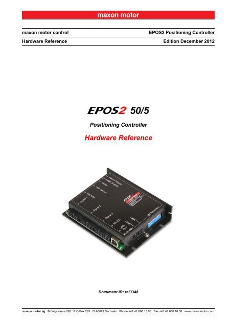
maxon motor control<br />
<strong>Hardware</strong> <strong>Reference</strong><br />
Positioning Controller<br />
<strong>Hardware</strong> <strong>Reference</strong><br />
Document ID: rel3348<br />
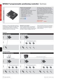
<strong>EPOS2</strong> Positioning Controller<br />
Edition December 2012<br />
maxon motor <strong>ag</strong> Brünigstrasse 220 P.O.Box 263 CH-6072 Sachseln Phone +41 41 666 15 00 Fax +41 41 666 16 <strong>50</strong> www.maxonmotor.com
PLEASE READ THIS FIRST<br />
These instructions are intended for qualified technical personnel. Prior commencing with any<br />
activities …<br />
• you must carefully read and understand this manual and<br />
• you must follow the instructions given therein.<br />
We have tried to provide you with all information necessary to install and commission the equipment in a<br />
secure, safe and time-saving manner. Our main focus is …<br />
• to familiarize you with all relevant technical aspects,<br />
• to let you know the easiest way of doing,<br />
• to alert you of any possibly dangerous situation you might encounter or that you might cause if<br />
you do not follow the description,<br />
• to write as little and to say as much as possible and<br />
• not to bore you with things you already know.<br />
Likewise, we tried to skip repetitive information! Thus, you will find things mentioned just once. If, for<br />
example, an earlier mentioned action fits other occasions you then will be directed to that text pass<strong>ag</strong>e<br />
with a respective reference.<br />
Follow any stated reference – observe respective information – then go back and continue with<br />
the task!<br />
PREREQUISITES FOR PERMISSION TO COMMENCE INSTALLATION<br />
The <strong>EPOS2</strong> <strong>50</strong>/5 is considered as partly completed machinery according to EU’s directive 2006/42/EC,<br />
Article 2, Clause (g) and therefore is intended to be incorporated into or assembled with other<br />
machinery or other partly completed machinery or equipment.<br />
You must not put the device into service, …<br />
• unless you have made completely sure that the other machinery – the surrounding system the device<br />
is intended to be incorporated to – fully complies with the requirements stated in the EU directive<br />
2006/42/EC!<br />
• unless the surrounding system fulfills all relevant health and safety aspects!<br />
• unless all respective interfaces have been established and fulfill the stated requirements!<br />
A-2 Document ID: rel3348<br />
maxon motor control<br />
<strong>EPOS2</strong> Positioning Controller<br />
Edition: December 2012<br />
© 2012 maxon motor. Subject to change without prior notice.<br />
<strong>EPOS2</strong> <strong>50</strong>/5 <strong>Hardware</strong> <strong>Reference</strong>
TABLE OF CONTENTS<br />
1 About this Document 5<br />
2 Introduction 9<br />
2.1 Documentation Structure . . . . . . . . . . . . . . . . . . . . . . . . . . . . . . . . . . . . . . . . . 9<br />
2.2 Safety Precautions. . . . . . . . . . . . . . . . . . . . . . . . . . . . . . . . . . . . . . . . . . . . . 10<br />
3 Technical Data 11<br />
3.1 Electrical Data . . . . . . . . . . . . . . . . . . . . . . . . . . . . . . . . . . . . . . . . . . . . . . . . 11<br />
3.2 Mechanical Data . . . . . . . . . . . . . . . . . . . . . . . . . . . . . . . . . . . . . . . . . . . . . . 14<br />
3.3 Environmental Conditions . . . . . . . . . . . . . . . . . . . . . . . . . . . . . . . . . . . . . . . 14<br />
3.4 Order Details . . . . . . . . . . . . . . . . . . . . . . . . . . . . . . . . . . . . . . . . . . . . . . . . . 15<br />
3.5 Standards . . . . . . . . . . . . . . . . . . . . . . . . . . . . . . . . . . . . . . . . . . . . . . . . . . . 15<br />
4 Connections 17<br />
4.1 Power Supply Connector (J1) . . . . . . . . . . . . . . . . . . . . . . . . . . . . . . . . . . . . 18<br />
4.2 Logic Supply Connector (J1A) . . . . . . . . . . . . . . . . . . . . . . . . . . . . . . . . . . . . 19<br />
4.3 <strong>Motor</strong> Connector (J2). . . . . . . . . . . . . . . . . . . . . . . . . . . . . . . . . . . . . . . . . . . 20<br />
4.3.1 maxon EC motor (brushless) . . . . . . . . . . . . . . . . . . . . . . . . . . . . . . . . . . . . . . . . . . . . . 20<br />
4.3.2 maxon DC motor with separated <strong>Motor</strong>/Encoder Cable. . . . . . . . . . . . . . . . . . . . . . . . . 20<br />
4.3.3 maxon DC motor with integrated <strong>Motor</strong>/Encoder Ribbon Cable . . . . . . . . . . . . . . . . . . 21<br />
4.4 Hall Sensor Connector (J3) . . . . . . . . . . . . . . . . . . . . . . . . . . . . . . . . . . . . . . 22<br />
4.5 Encoder Connector (J4). . . . . . . . . . . . . . . . . . . . . . . . . . . . . . . . . . . . . . . . . 23<br />
4.6 Signal 1 Connector (J5) . . . . . . . . . . . . . . . . . . . . . . . . . . . . . . . . . . . . . . . . . 25<br />
4.6.1 Auxiliary Supply Volt<strong>ag</strong>e for DigINs . . . . . . . . . . . . . . . . . . . . . . . . . . . . . . . . . . . . . . . . 25<br />
4.6.2 Digital Inputs 7 and 8 “High Speed Command” . . . . . . . . . . . . . . . . . . . . . . . . . . . . . . . 26<br />
4.6.3 Digital Inputs 9 and 10 “High Speed Command” . . . . . . . . . . . . . . . . . . . . . . . . . . . . . . 28<br />
4.6.4 Digital Output 5 “High Speed Output” . . . . . . . . . . . . . . . . . . . . . . . . . . . . . . . . . . . . . . 29<br />
4.7 Signal 2 Connector (J6) . . . . . . . . . . . . . . . . . . . . . . . . . . . . . . . . . . . . . . . . . 30<br />
4.7.1 Digital Inputs 1, 2 and 3 . . . . . . . . . . . . . . . . . . . . . . . . . . . . . . . . . . . . . . . . . . . . . . . . . 31<br />
4.7.2 Digital Inputs 4, 5 and 6 . . . . . . . . . . . . . . . . . . . . . . . . . . . . . . . . . . . . . . . . . . . . . . . . . 32<br />
4.7.3 Digital Input 11 . . . . . . . . . . . . . . . . . . . . . . . . . . . . . . . . . . . . . . . . . . . . . . . . . . . . . . . . 34<br />
4.7.4 Supply Volt<strong>ag</strong>e for DigOUTs . . . . . . . . . . . . . . . . . . . . . . . . . . . . . . . . . . . . . . . . . . . . . 35<br />
4.7.5 Digital Outputs 1 and 2 . . . . . . . . . . . . . . . . . . . . . . . . . . . . . . . . . . . . . . . . . . . . . . . . . 35<br />
4.7.6 Digital Outputs 3 and 4 . . . . . . . . . . . . . . . . . . . . . . . . . . . . . . . . . . . . . . . . . . . . . . . . . 36<br />
4.8 Signal 3 Connector (J7) . . . . . . . . . . . . . . . . . . . . . . . . . . . . . . . . . . . . . . . . . 37<br />
4.8.1 Analog Inputs 1 and 2 . . . . . . . . . . . . . . . . . . . . . . . . . . . . . . . . . . . . . . . . . . . . . . . . . . 37<br />
4.8.2 Analog Output 1 . . . . . . . . . . . . . . . . . . . . . . . . . . . . . . . . . . . . . . . . . . . . . . . . . . . . . . . 38<br />
4.9 RS232 Connector (J8) . . . . . . . . . . . . . . . . . . . . . . . . . . . . . . . . . . . . . . . . . . 39<br />
4.10 USB Connector (J9). . . . . . . . . . . . . . . . . . . . . . . . . . . . . . . . . . . . . . . . . . . . 40<br />
4.11 CAN Connector (J10, J11). . . . . . . . . . . . . . . . . . . . . . . . . . . . . . . . . . . . . . . 41<br />
maxon motor control<br />
<strong>EPOS2</strong> Positioning Controller Document ID: rel3348 A-3<br />
<strong>EPOS2</strong> <strong>50</strong>/5 <strong>Hardware</strong> <strong>Reference</strong> Edition: December 2012<br />
© 2012 maxon motor. Subject to change without prior notice.
4.12 CAN Configuration (JP1) . . . . . . . . . . . . . . . . . . . . . . . . . . . . . . . . . . . . . . . . 42<br />
4.12.1 CAN ID (Node Address) . . . . . . . . . . . . . . . . . . . . . . . . . . . . . . . . . . . . . . . . . . . . . . . . 42<br />
4.12.2 CAN Bus Termination . . . . . . . . . . . . . . . . . . . . . . . . . . . . . . . . . . . . . . . . . . . . . . . . . . 43<br />
4.13 Status LEDs . . . . . . . . . . . . . . . . . . . . . . . . . . . . . . . . . . . . . . . . . . . . . . . . . . 44<br />
A-4 Document ID: rel3348<br />
maxon motor control<br />
<strong>EPOS2</strong> Positioning Controller<br />
Edition: December 2012<br />
© 2012 maxon motor. Subject to change without prior notice.<br />
<strong>EPOS2</strong> <strong>50</strong>/5 <strong>Hardware</strong> <strong>Reference</strong>
1 About this Document<br />
1.1 Intended Purpose<br />
The purpose of the present document is to familiarize you with the described equipment and the tasks<br />
on safe and adequate installation and/or commissioning.<br />
Observing the described instructions in this document will help you …<br />
• to avoid dangerous situations,<br />
• to keep installation and/or commissioning time at a minimum and<br />
• to increase reliability and service life of the described equipment.<br />
Use for other and/or additional purposes is not permitted. maxon motor, the manufacturer of the equipment<br />
described, does not assume any liability for loss or dam<strong>ag</strong>e that may arise from any other and/or<br />
additional use than the intended purpose.<br />
1.2 Target Audience<br />
This document is meant for trained and skilled personnel working with the equipment described. It conveys<br />
information on how to understand and fulfill the respective work and duties.<br />
This document is a reference book. It does require particular knowledge and expertise specific to the<br />
equipment described.<br />
1.3 How to use<br />
Take note of the following notations and codes which will be used throughout the document.<br />
1.4 Symbols and Signs<br />
Notation Explanation<br />
(n) referring to an item (such as order number, list item, etc.)<br />
denotes “see”, “see also”, “take note of” or “go to”<br />
Table 1-1 Notations used in this Document<br />
1.4.1 Safety Alerts<br />
Take note of when and why the alerts will be used and what the consequences are if you should<br />
fail to observe them!<br />
Safety alerts are composed of…<br />
• a signal word,<br />
• a description of type and/or source of the danger,<br />
• the consequence if the alert is being ignored, and<br />
• explanations on how to avoid the hazard.<br />
Following types will be used:<br />
1) DANGER<br />
Indicates an imminently hazardous situation. If not avoided, the situation will result in death<br />
or serious injury.<br />
2) WARNING<br />
Indicates a potentially hazardous situation. If not avoided, the situation can result in death or<br />
serious injury.<br />
maxon motor control<br />
<strong>EPOS2</strong> Positioning Controller Document ID: rel3348 1-5<br />
<strong>EPOS2</strong> <strong>50</strong>/5 <strong>Hardware</strong> <strong>Reference</strong> Edition: December 2012<br />
© 2012 maxon motor. Subject to change without prior notice.
3) CAUTION<br />
Indicates a probable hazardous situation and is also used to alert <strong>ag</strong>ainst unsafe practices. If<br />
not avoided, the situation may result in minor or moderate injury.<br />
Example:<br />
DANGER<br />
High Volt<strong>ag</strong>e and/or Electrical Shock<br />
Touching live wires causes death or serious injuries!<br />
• Make sure that neither end of cable is connected to life power!<br />
• Make sure that power source cannot be eng<strong>ag</strong>ed while work is in process!<br />
• Obey lock-out/t<strong>ag</strong>-out procedures!<br />
• Make sure to securely lock any power eng<strong>ag</strong>ing equipment <strong>ag</strong>ainst unintentional eng<strong>ag</strong>ement and<br />
t<strong>ag</strong> with your name!<br />
1.4.2 Prohibited Actions and Mandatory Actions<br />
The signs define prohibitive actions. So, you must not!<br />
Examples:<br />
Do not touch! Do not operate!<br />
The signs point out actions to avoid a hazard. So, you must!<br />
Examples:<br />
Unplug! T<strong>ag</strong> before work!<br />
1.4.3 Informatory Signs<br />
Requirement / Note / Remark<br />
Indicates an action you must perform prior continuing or refers to information on a particular item.<br />
Best Practice<br />
Gives advice on the easiest and best way to proceed.<br />
Material Dam<strong>ag</strong>e<br />
Points out information particular to potential dam<strong>ag</strong>e of equipment.<br />
<strong>Reference</strong><br />
Refers to particular information provided by other parties.<br />
1-6 Document ID: rel3348<br />
maxon motor control<br />
<strong>EPOS2</strong> Positioning Controller<br />
Edition: December 2012<br />
© 2012 maxon motor. Subject to change without prior notice.<br />
<strong>EPOS2</strong> <strong>50</strong>/5 <strong>Hardware</strong> <strong>Reference</strong>
1.5 Trademarks and Brand Names<br />
For easier legibility, registered brand names are listed below and will not be further t<strong>ag</strong>ged with their<br />
respective trademark. It must be understood that the brands (the below list is not necessarily concluding)<br />
are protected by copyright and/or other intellectual property rights even if their legal trademarks are<br />
omitted in the later course of this document.<br />
1.6 Copyright<br />
The brand name(s) … … is/are a registered trademark(s) of …<br />
Adobe® Reader® © Adobe Systems Incorporated, USA-San Jose, CA<br />
Micro-Fit<br />
Mini-Fit Jr.<br />
© Molex, USA-Lisle, IL<br />
Pentium® © Intel Corporation, USA-Santa Clara, CA<br />
Windows® © Microsoft Corporation, USA-Redmond, WA<br />
Table 1-2 Brand Names and Trademark Owners<br />
© 2012 maxon motor. All rights reserved.<br />
The present document – including all parts thereof – is protected by copyright. Any use (including reproduction,<br />
translation, microfilming and other means of electronic data processing) beyond the narrow<br />
restrictions of the copyright law without the prior approval of maxon motor <strong>ag</strong>, is not permitted and subject<br />
to persecution under the applicable law.<br />
maxon motor <strong>ag</strong><br />
Brünigstrasse 220<br />
P.O.Box 263<br />
CH-6072 Sachseln<br />
Switzerland<br />
Phone +41 41 666 15 00<br />
Fax +41 41 666 16 <strong>50</strong><br />
www.maxonmotor.com<br />
maxon motor control<br />
<strong>EPOS2</strong> Positioning Controller Document ID: rel3348 1-7<br />
<strong>EPOS2</strong> <strong>50</strong>/5 <strong>Hardware</strong> <strong>Reference</strong> Edition: December 2012<br />
© 2012 maxon motor. Subject to change without prior notice.
••p<strong>ag</strong>e intentionally left blank••<br />
1-8 Document ID: rel3348<br />
maxon motor control<br />
<strong>EPOS2</strong> Positioning Controller<br />
Edition: December 2012<br />
© 2012 maxon motor. Subject to change without prior notice.<br />
<strong>EPOS2</strong> <strong>50</strong>/5 <strong>Hardware</strong> <strong>Reference</strong>
2 Introduction<br />
The present document provides you with information on the <strong>EPOS2</strong> <strong>50</strong>/5 Positioning Controller’s hardware.<br />
It contains…<br />
• performance data and specifications,<br />
• information on connections and pin assignment and<br />
• wiring examples.<br />
maxon motor control’s <strong>EPOS2</strong> <strong>50</strong>/5 is a small-sized, full digital, smart motion controller. Due to its flexible<br />
and high efficient power st<strong>ag</strong>e, the <strong>EPOS2</strong> <strong>50</strong>/5 drives brushed DC motors with digital encoder as<br />
well as brushless EC motors with digital Hall sensors and encoder.<br />
The sinusoidal current commutation by space vector control offers the possibility to drive brushless EC<br />
motors with minimal torque ripple and low noise. The integrated position, velocity and current control<br />
functionality allows sophisticated positioning applications. The <strong>EPOS2</strong> <strong>50</strong>/5 is especially designed being<br />
commanded and controlled as a slave node in a CANopen network. In addition, the unit can be operated<br />
via any USB or RS232 interface.<br />
Find the latest edition of the present document, as well as additional documentation and software to the<br />
<strong>EPOS2</strong> <strong>50</strong>/5 Positioning Controller also on the internet: www.maxonmotor.com<br />
2.1 Documentation Structure<br />
The present document is part of a documentation set. Please find below an overview on the documentation<br />
hierarchy and the interrelationship of its individual parts:<br />
Figure 2-1 Documentation Structure<br />
maxon motor control<br />
<strong>EPOS2</strong> Positioning Controller Document ID: rel3348 2-9<br />
<strong>EPOS2</strong> <strong>50</strong>/5 <strong>Hardware</strong> <strong>Reference</strong> Edition: December 2012<br />
© 2012 maxon motor. Subject to change without prior notice.
2.2 Safety Precautions<br />
Prior continuing …<br />
• make sure you have read and understood chapter “ PLEASE READ THIS FIRST” on p<strong>ag</strong>e A-2,<br />
• do not eng<strong>ag</strong>e with any work unless you possess the stated skills (chapter “1.2 Target Audience”<br />
on p<strong>ag</strong>e 1-5),<br />
• refer to chapter “1.4 Symbols and Signs” on p<strong>ag</strong>e 1-5 to understand the subsequently used<br />
indicators,<br />
• you must observe any regulation applicable in the country and/or at the site of implementation<br />
with regard to health and safety/accident prevention and/or environmental protection,<br />
• take note of the subsequently used indicators and follow them at all times.<br />
DANGER<br />
High Volt<strong>ag</strong>e and/or Electrical Shock<br />
Touching live wires causes death or serious injuries!<br />
• Consider any power cable as connected to life power, unless having proven the opposite!<br />
• Make sure that neither end of cable is connected to life power!<br />
• Make sure that power source cannot be eng<strong>ag</strong>ed while work is in process!<br />
• Obey lock-out/t<strong>ag</strong>-out procedures!<br />
• Make sure to securely lock any power eng<strong>ag</strong>ing equipment <strong>ag</strong>ainst unintentional eng<strong>ag</strong>ement and<br />
t<strong>ag</strong> with your name!<br />
Requirements<br />
• Make sure that all associated devices and components are installed according to local regulations.<br />
• Be aware that, by principle, an electronic apparatus can not be considered fail-safe. Therefore, you<br />
must make sure that any machine/apparatus has been fitted with independent monitoring and safety<br />
equipment. If the machine/apparatus should break down, if it is operated incorrectly, if the control unit<br />
breaks down or if the cables break or get disconnected, etc., the complete drive system must return –<br />
and be kept – in a safe operating mode.<br />
• Be aware that you are not entitled to perform any repair on components supplied by maxon motor.<br />
Best Practice<br />
• For initial operation, make sure that the motor is free running. If not the case, mechanically disconnect<br />
the motor from the load.<br />
Maximal permitted Supply Volt<strong>ag</strong>e<br />
• Make sure that supply power is between 11…<strong>50</strong> VDC.<br />
• Supply volt<strong>ag</strong>es above 55 VDC will destroy the unit.<br />
• Wrong polarity will destroy the unit.<br />
Electrostatic Sensitive Device (ESD)<br />
• Make sure to wear working cloth in compliance with ESD.<br />
• Handle device with extra care.<br />
2-10 Document ID: rel3348<br />
maxon motor control<br />
<strong>EPOS2</strong> Positioning Controller<br />
Edition: December 2012<br />
© 2012 maxon motor. Subject to change without prior notice.<br />
<strong>EPOS2</strong> <strong>50</strong>/5 <strong>Hardware</strong> <strong>Reference</strong>
3 Technical Data<br />
3.1 Electrical Data<br />
Rating<br />
Nominal power supply volt<strong>ag</strong>e V CC<br />
Table 3-3 Electrical Data – Rating<br />
Table 3-4 Electrical Data – Inputs<br />
11…<strong>50</strong> VDC<br />
Nominal logic supply volt<strong>ag</strong>e V C (optional) 11…<strong>50</strong> VDC<br />
Absolute minimum supply volt<strong>ag</strong>e 10 VDC<br />
Absolute max. supply volt<strong>ag</strong>e 54 VDC<br />
Max. output volt<strong>ag</strong>e 0.9 • V CC<br />
Max. output current I max (
Outputs<br />
Digital Output 1 (“General Purpose”), optically isolated max. 24 VDC (I L
Connections<br />
Power<br />
Supply<br />
Logic<br />
Supply<br />
<strong>Motor</strong><br />
Hall<br />
Signal 1<br />
Signal 2<br />
Signal 3<br />
RS232<br />
USB<br />
CAN 1<br />
CAN 2<br />
Encoder<br />
On board:<br />
Suitable plug:<br />
Suitable terminal:<br />
On board:<br />
Suitable plug:<br />
Suitable terminal:<br />
On board:<br />
Suitable plug:<br />
Suitable terminal:<br />
On board:<br />
Suitable plug:<br />
Suitable terminal:<br />
On board:<br />
Suitable plug:<br />
Suitable terminal:<br />
On board:<br />
Suitable plug:<br />
Suitable terminal:<br />
On board:<br />
Suitable plug:<br />
Suitable terminal:<br />
On board:<br />
Suitable plug:<br />
Suitable terminal:<br />
On board:<br />
Suitable plug:<br />
On board:<br />
Suitable plug:<br />
Suitable terminal:<br />
On board:<br />
Suitable plug:<br />
Suitable terminal:<br />
On board:<br />
Suitable locking clip:<br />
Table 3-10 Electrical Data – Connections<br />
dual row male header (2 poles) Molex Mini-Fit Jr<br />
dual row female receptacle (2 poles) Molex Mini-Fit Jr. 39-01-2020<br />
female crimp terminal Molex Mini-Fit Jr. 44476-xxxx (AWG 16-20)<br />
dual row male header (2 poles) Molex Mini-Fit Jr<br />
dual row female receptacle (2 poles) Molex Mini-Fit Jr. 39-01-2020<br />
female crimp terminal Molex Mini-Fit Jr. 44476-xxxx (AWG 16-20)<br />
dual row male header (4 poles) Molex Mini-Fit Jr<br />
dual row female receptacle (4 poles) Molex Mini-Fit Jr. 39-01-2040<br />
female crimp terminal Molex Mini-Fit Jr. 44476-xxxx (AWG 16-20)<br />
dual row male header (6 poles) Molex Micro-Fit 3.0<br />
dual row female receptacle (6 poles) Molex Micro-Fit 3.0 430-25-0600<br />
female crimp terminal Molex Micro-Fit 3.0 43030-xxxx (AWG 20-30)<br />
dual row male header (12 poles) Molex Micro-Fit 3.0<br />
dual row female receptacle (12 poles) Molex Micro-Fit 3.0 430-25-1200<br />
female crimp terminal Molex Micro-Fit 3.0 43030-xxxx (AWG 20-30)<br />
dual row male header (16 poles) Molex Micro-Fit 3.0<br />
dual row female receptacle (16 poles) Molex Micro-Fit 3.0 430-25-1600<br />
female crimp terminal Molex Micro-Fit 3.0 43030-xxxx (AWG 20-30)<br />
dual row male header (8 poles) Molex Micro-Fit 3.0<br />
dual row female receptacle (8 poles) Molex Micro-Fit 3.0 430-25-0800<br />
female crimp terminal Molex Micro-Fit 3.0 43030-xxxx (AWG 20-30)<br />
dual row male header (6 poles) Molex Micro-Fit 3.0<br />
dual row female receptacle (6 poles) Molex Micro-Fit 3.0 430-25-0600<br />
female crimp terminal Molex Micro-Fit 3.0 43030-xxxx (AWG 20-30)<br />
USB connector type B jack (4 poles)<br />
Standard USB cable with type B plug connector (4 poles)<br />
dual row male header (4 poles) Molex Micro-Fit 3.0<br />
dual row female receptacle (4 poles) Molex Micro-Fit 3.0 430-25-0400<br />
female crimp terminal Molex Micro-Fit 3.0 43030-xxxx (AWG 20-30)<br />
dual row male header (4 poles) Molex Micro-Fit 3.0<br />
dual row female receptacle (4 poles) Molex Micro-Fit 3.0 430-25-0400<br />
female crimp terminal Molex Micro-Fit 3.0 43030-xxxx (AWG 20-30)<br />
Plug DIN41651 (10 poles) for flat band cable, pitch 1.27mm, AWG 28<br />
Tyco C42334-A421-C42 (right) / Tyco C42334-A421-C52 (left)<br />
maxon motor control<br />
<strong>EPOS2</strong> Positioning Controller Document ID: rel3348 3-13<br />
<strong>EPOS2</strong> <strong>50</strong>/5 <strong>Hardware</strong> <strong>Reference</strong> Edition: December 2012<br />
© 2012 maxon motor. Subject to change without prior notice.
3.2 Mechanical Data<br />
Mechanical Data<br />
Weight approx. 240 g<br />
Dimensions (L x W x H) 120 x 93.5 x 27 mm<br />
Mounting plate for M3 screws<br />
Table 3-11 Mechanical Data<br />
Figure 3-2 Dimensional Drawing [mm]<br />
3.3 Environmental Conditions<br />
Environmental Condition<br />
Operation -10…+45°C<br />
Temperature<br />
Extended Range *1) +45…+80°C / Derating: -0.143 A/°C<br />
Stor<strong>ag</strong>e -40…+85°C<br />
Humidity 20…80% (condensation not permitted)<br />
Remark:<br />
*1) Operation within the extended temperature range is permitted. However, a respective derating (declination of<br />
max. output current) as to the stated value will apply.<br />
Table 3-12 Environmental Conditions<br />
3-14 Document ID: rel3348<br />
maxon motor control<br />
<strong>EPOS2</strong> Positioning Controller<br />
Edition: December 2012<br />
© 2012 maxon motor. Subject to change without prior notice.<br />
<strong>EPOS2</strong> <strong>50</strong>/5 <strong>Hardware</strong> <strong>Reference</strong>
3.4 Order Details<br />
Order Details<br />
<strong>EPOS2</strong> <strong>50</strong>/5 Order number 347717<br />
Table 3-13 Order Details<br />
3.5 Standards<br />
The described device has been successfully tested for compliance with the below listed standards. In<br />
practical terms, only the complete system (the fully operational equipment comprising all individual components,<br />
such as motor, servo controller, power supply unit, EMC filter, cabling etc.) can undergo an<br />
EMC test to ensure interference-free operation.<br />
Important Notice<br />
The device’s compliance with the mentioned standards does not imply its compliance within the final,<br />
ready to operate setup. In order to achieve compliance of your operational system, you must perform<br />
EMC testing of the involved equipment as a whole.<br />
Generic Standards<br />
Applied Standards<br />
Environmental<br />
Standards<br />
Table 3-14 Standards<br />
Electrom<strong>ag</strong>netic Compatibility<br />
IEC/EN 61000-6-2 Immunity for industrial environments<br />
IEC/EN 61000-6-3<br />
IEC/EN 61000-6-3<br />
IEC/EN 5<strong>50</strong>22<br />
(CISPR22)<br />
Emission standard for residential, commercial and lightindustrial<br />
environments<br />
Radio disturbance characteristics / radio interference<br />
IEC/EN 61000-4-2 Electrostatic discharge immunity test 8 kV/6 kV<br />
IEC/EN 61000-4-3<br />
Radiated, radio-frequency, electrom<strong>ag</strong>netic field immunity<br />
test >10 V/m<br />
IEC/EN 61000-4-4 Electrical fast transient/burst immunity test ±1 kV/±2 kV<br />
IEC/EN 61000-4-6<br />
Immunity to conducted disturbances, induced by radiofrequency<br />
fields 10 Vrms<br />
IEC/EN 61000-4-8 Power frequency m<strong>ag</strong>netic field 30 A/m<br />
Others<br />
IEC/EN 60068-2-6 Environmental testing – Test Fc: Vibration (sinusoidal)<br />
MIL-STD-810F Random transport<br />
Safety Standards UL File Number E172472 or E92481; unassembled printed circuit board<br />
maxon motor control<br />
<strong>EPOS2</strong> Positioning Controller Document ID: rel3348 3-15<br />
<strong>EPOS2</strong> <strong>50</strong>/5 <strong>Hardware</strong> <strong>Reference</strong> Edition: December 2012<br />
© 2012 maxon motor. Subject to change without prior notice.
••p<strong>ag</strong>e intentionally left blank••<br />
3-16 Document ID: rel3348<br />
maxon motor control<br />
<strong>EPOS2</strong> Positioning Controller<br />
Edition: December 2012<br />
© 2012 maxon motor. Subject to change without prior notice.<br />
<strong>EPOS2</strong> <strong>50</strong>/5 <strong>Hardware</strong> <strong>Reference</strong>
4 Connections<br />
Figure 4-3 Interfaces – Designations and Location<br />
Figure 4-4 Wiring Di<strong>ag</strong>ram<br />
maxon motor control<br />
<strong>EPOS2</strong> Positioning Controller Document ID: rel3348 4-17<br />
<strong>EPOS2</strong> <strong>50</strong>/5 <strong>Hardware</strong> <strong>Reference</strong> Edition: December 2012<br />
© 2012 maxon motor. Subject to change without prior notice.
4.1 Power Supply Connector (J1)<br />
Best Practice<br />
Keep the motor mechanically disconnected during setup and adjustment phase.<br />
DETERMINATION OF POWER SUPPLY<br />
Basically, any power supply may be used, provided it meets below stated minimal requirements.<br />
Power Supply Requirements<br />
Output volt<strong>ag</strong>e V CC min. 11 VDC; V CC max. <strong>50</strong> VDC<br />
Absolute output volt<strong>ag</strong>e min. 10 VDC; max. 54 VDC<br />
Output current Depending on load (continuous max. 5 A / acceleration, short-time max. 10 A)<br />
1) Calculate required volt<strong>ag</strong>e under load using following scheme (the formula takes a max. PWM<br />
cycle of 90% and a max. volt<strong>ag</strong>e drop of -1 V at <strong>EPOS2</strong> <strong>50</strong>/5 into account):<br />
KNOWN VALUES:<br />
• Operating torque MB [mNm]<br />
• Operating speed nB [min-1] • Nominal motor volt<strong>ag</strong>e UN [Volt]<br />
• <strong>Motor</strong> no-load speed at UN , n0 [min-1] • Speed/torque gradient of the motor Δn/ΔM [min-1 mNm-1] SOUGHT VALUE:<br />
• Supply volt<strong>ag</strong>e VCC [Volt]<br />
SOLUTION:<br />
VCC =<br />
UN nO 2) Choose power supply capable as to above calculation. Thereby consider:<br />
a) During braking of the load, the power supply must be capable of buffering the fed back<br />
energy, e.g. in a capacitor.<br />
b) When using an electronically stabilized power supply, observe that the overcurrent protection<br />
must not be activated in any operating state.<br />
Figure 4-5 Power Connector (J1)<br />
Pin Signal Description<br />
1 Power_Gnd Ground of supply volt<strong>ag</strong>e<br />
2 +V CC Power supply volt<strong>ag</strong>e +11…+<strong>50</strong> VDC<br />
Accessories Cable EPOS Power Cable (275829)<br />
Notes<br />
------ Δn<br />
nB + -------- ⋅ M 1<br />
⋅<br />
ΔM B ⋅ ------ + 1[ V]<br />
0.9<br />
Suitable connector<br />
Suitable crimp terminals<br />
Suitable hand crimper<br />
Molex Mini-Fit Jr. 2 poles (39-01-2020)<br />
Molex Mini-Fit Jr. female crimp terminals (44476-xxxx)<br />
Molex hand crimper (63819-0900)<br />
4-18 Document ID: rel3348<br />
maxon motor control<br />
<strong>EPOS2</strong> Positioning Controller<br />
Edition: December 2012<br />
© 2012 maxon motor. Subject to change without prior notice.<br />
<strong>EPOS2</strong> <strong>50</strong>/5 <strong>Hardware</strong> <strong>Reference</strong>
4.2 Logic Supply Connector (J1A)<br />
By default, the logic is powered by the regular supply volt<strong>ag</strong>e. Optionally, you may wish to feed the logic<br />
supply volt<strong>ag</strong>e separately, permitting a safe and economical power backup feature.<br />
Basically, any power supply may be used, provided it meets below stated minimal requirements.<br />
Power Supply Requirements<br />
Output volt<strong>ag</strong>e V C min. 11 VDC; V C max. <strong>50</strong> VDC<br />
Absolute output volt<strong>ag</strong>e min. 10 VDC; max. 54 VDC<br />
Min. output power P C min. 5 W<br />
Figure 4-6 Power Connector (J1A)<br />
Pin Signal Description<br />
1 Power_Gnd Ground of supply volt<strong>ag</strong>e<br />
2 +V C Logic supply volt<strong>ag</strong>e +11…+<strong>50</strong> VDC<br />
Accessories Cable EPOS Power Cable (275829)<br />
Notes<br />
Suitable connector<br />
Suitable crimp terminals<br />
Suitable hand crimper<br />
Molex Mini-Fit Jr. 2 poles (39-01-2020)<br />
Molex Mini-Fit Jr. female crimp terminals (44476-xxxx)<br />
Molex hand crimper (63819-0900)<br />
maxon motor control<br />
<strong>EPOS2</strong> Positioning Controller Document ID: rel3348 4-19<br />
<strong>EPOS2</strong> <strong>50</strong>/5 <strong>Hardware</strong> <strong>Reference</strong> Edition: December 2012<br />
© 2012 maxon motor. Subject to change without prior notice.
4.3 <strong>Motor</strong> Connector (J2)<br />
By default, the controller is set to drive either maxon EC motor (brushless) or maxon DC motor<br />
(brushed) with separated motor/encoder cable. Using a maxon DC motor with integrated motor/<br />
encoder ribbon cable, you will need to change the jumpers JP2 and JP3.<br />
Figure 4-7 <strong>Motor</strong> Connector (J2)<br />
Accessories Cable EPOS <strong>Motor</strong> Cable (275851)<br />
Notes<br />
Suitable connector<br />
Suitable crimp terminals<br />
Suitable hand crimper<br />
4.3.1 maxon EC motor (brushless)<br />
Pin Signal Description<br />
1 <strong>Motor</strong> winding 1 EC motor: Winding 1<br />
2 <strong>Motor</strong> winding 2 EC motor: Winding 2<br />
3 <strong>Motor</strong> winding 3 EC motor: Winding 3<br />
4 <strong>Motor</strong> shield Cable shield<br />
4.3.2 maxon DC motor with separated <strong>Motor</strong>/Encoder Cable<br />
Pin Signal Description<br />
1 <strong>Motor</strong> (+M) DC motor: <strong>Motor</strong> +<br />
2 <strong>Motor</strong> (-M) DC motor: <strong>Motor</strong> -<br />
3 do not connect<br />
4 <strong>Motor</strong> shield Cable shield<br />
Molex Mini-Fit Jr. 4 poles (39-01-2040)<br />
Molex Mini-Fit Jr. female crimp terminals (44476-xxxx)<br />
Molex hand crimper (63819-0900)<br />
4-20 Document ID: rel3348<br />
maxon motor control<br />
<strong>EPOS2</strong> Positioning Controller<br />
Edition: December 2012<br />
© 2012 maxon motor. Subject to change without prior notice.<br />
<strong>EPOS2</strong> <strong>50</strong>/5 <strong>Hardware</strong> <strong>Reference</strong>
4.3.3 maxon DC motor with integrated <strong>Motor</strong>/Encoder Ribbon Cable<br />
STOP!<br />
Check on safety precautions before continuing (p<strong>ag</strong>e 2-10).<br />
1) Open housing and find jumpers JP2 and JP3.<br />
2) Set jumpers JP2 and JP3 to “closed” position (Figure 4-9, right).<br />
3) For encoder connections chapter “4.5 Encoder Connector (J4)” on p<strong>ag</strong>e 4-23.<br />
Figure 4-8 Jumpers JP2/JP3 – Location and Factory Setting<br />
Figure 4-9 Jumpers JP2/JP3 – open (left) / closed (right)<br />
maxon motor control<br />
<strong>EPOS2</strong> Positioning Controller Document ID: rel3348 4-21<br />
<strong>EPOS2</strong> <strong>50</strong>/5 <strong>Hardware</strong> <strong>Reference</strong> Edition: December 2012<br />
© 2012 maxon motor. Subject to change without prior notice.
4.4 Hall Sensor Connector (J3)<br />
Hall sensors are required to detect the rotor position of maxon EC motors (brushless).<br />
Suitable Hall effect sensors IC use «Schmitt trigger» with open collector output.<br />
Hall sensor supply volt<strong>ag</strong>e +5 VDC<br />
Max. Hall sensor supply current 30 mA<br />
Input volt<strong>ag</strong>e 0…+24 VDC<br />
Logic 0 typically 2.4 VDC<br />
Internal pull-up resistor 2.7 kΩ (<strong>ag</strong>ainst +5 VDC)<br />
Figure 4-10 Hall Sensor Input Circuit<br />
Figure 4-11 Hall Sensor Connector (J3)<br />
Pin Signal Description<br />
1 Hall sensor 1 Hall sensor 1 Input<br />
2 Hall sensor 2 Hall sensor 2 Input<br />
3 Hall sensor 3 Hall sensor 3 Input<br />
4 GND Ground of Hall sensor supply<br />
5 +VHall Hall sensor supply volt<strong>ag</strong>e +5 VDC / 30 mA<br />
6 Hall shield Cable shield<br />
Accessories Cable EPOS Hall Sensor Cable (275878)<br />
Notes<br />
Suitable connector<br />
Suitable crimp terminals<br />
Suitable hand crimper<br />
Molex Micro-Fit 3.0 6 poles (430-25-0600)<br />
Molex Micro-Fit 3.0 female crimp terminals (43030-xxxx)<br />
Molex hand crimper (63819-0000)<br />
4-22 Document ID: rel3348<br />
maxon motor control<br />
<strong>EPOS2</strong> Positioning Controller<br />
Edition: December 2012<br />
© 2012 maxon motor. Subject to change without prior notice.<br />
<strong>EPOS2</strong> <strong>50</strong>/5 <strong>Hardware</strong> <strong>Reference</strong>
4.5 Encoder Connector (J4)<br />
Best Practice<br />
The use of encoder with built-in line driver is mandatory.<br />
Even though 2-channel will do, we strongly recommend to use only 3-channel versions!<br />
Implemented are three high-speed RS422 receivers featuring fault detection circuitry and fault status<br />
outputs. The receivers’ inputs feature fault thresholds that detect the device’s “not in valid state”.<br />
The receivers indicate whether a receiver input is in open circuit condition (except index channel), shortcircuit<br />
condition, or beyond the common mode range (smaller -10 V or higher +13.2 V). They also generate<br />
a fault indication if the differential input volt<strong>ag</strong>e drops below the 475 mV threshold.<br />
By default, the controller is set for a <strong>50</strong>0 count per turn encoder. For other encoders, you will need to<br />
adjust respective settings via software.<br />
Encoder supply volt<strong>ag</strong>e +5 VDC<br />
Max. encoder supply current 100 mA<br />
Min. differential Input volt<strong>ag</strong>e ± 475 mV<br />
Line receiver (internal) EIA RS422 Standard<br />
Max. encoder input frequency 5 MHz<br />
Figure 4-12 Encoder Input Circuit (Channels A and B)<br />
Figure 4-13 Encoder Input Circuit (Index Channel)<br />
maxon motor control<br />
<strong>EPOS2</strong> Positioning Controller Document ID: rel3348 4-23<br />
<strong>EPOS2</strong> <strong>50</strong>/5 <strong>Hardware</strong> <strong>Reference</strong> Edition: December 2012<br />
© 2012 maxon motor. Subject to change without prior notice.
Figure 4-14 Encoder Connector (J4)<br />
Pin Signal Description<br />
1<br />
EC motor: none<br />
DC motor: <strong>Motor</strong> +<br />
EC motor: not connected<br />
DC motor: + <strong>Motor</strong> *1)<br />
2 +5 VDC / 100 mA Encoder supply volt<strong>ag</strong>e<br />
3 GND Ground<br />
4<br />
EC motor: none<br />
DC motor: <strong>Motor</strong> -<br />
EC motor: not connected<br />
DC motor: - <strong>Motor</strong> *1)<br />
5 Channel A\ Channel A complement<br />
6 Channel A Channel A<br />
7 Channel B\ Channel B complement<br />
8 Channel B Channel B<br />
9 Channel I\ Index complement<br />
10 Channel I Index<br />
REMARK:<br />
*1) may require change of jumper (J2 / J3) settings (chapter “4.3.3 maxon DC motor with<br />
integrated <strong>Motor</strong>/Encoder Ribbon Cable” on p<strong>ag</strong>e 4-21)<br />
Best Practice<br />
Among other encoders, pin out perfectly suits…<br />
• maxon digital MR-Encoder type S, M, ML, L all with Line Driver<br />
• maxon digital encoder HEDL 55_ with Line Driver RS422<br />
Accessories Cable EPOS Encoder Cable (275934)<br />
Notes Suitable connector DIN 41651 Plug, pitch 2.54 mm, 10 poles, plug strain relief<br />
4-24 Document ID: rel3348<br />
maxon motor control<br />
<strong>EPOS2</strong> Positioning Controller<br />
Edition: December 2012<br />
© 2012 maxon motor. Subject to change without prior notice.<br />
<strong>EPOS2</strong> <strong>50</strong>/5 <strong>Hardware</strong> <strong>Reference</strong>
4.6 Signal 1 Connector (J5)<br />
Contains differential “High Speed” digital inputs and outputs.<br />
Figure 4-15 Signal 1 Connector (J5)<br />
Pin Signal Description<br />
1 DigIN10/ Digital Input 10 “High Speed Command” complement<br />
2 DigIN10 Digital Input 10 “High Speed Command”<br />
3 DigIN9/ Digital Input 9 “High Speed Command” complement<br />
4 DigIN9 Digital Input 9 “High Speed Command”<br />
5 DigIN7/ Digital Input 7 “High Speed Command” complement<br />
6 DigIN7 Digital Input 7 “High Speed Command”<br />
7 DigIN8/ Digital Input 8 “High Speed Command” complement<br />
8 DigIN8 Digital Input 8 “High Speed Command”<br />
9 +V AUX Auxiliary output volt<strong>ag</strong>e (+5 VDC / 1<strong>50</strong> mA)<br />
10 D_Gnd Digital signal ground<br />
11 DigOUT5/ Digital Output 5 “High Speed Output” complement<br />
12 DigOUT5 Digital Output 5 “High Speed Output”<br />
Accessories Cable EPOS Signal Cable 2 (300586)<br />
Notes<br />
Suitable connector<br />
Suitable crimp terminals<br />
Suitable hand crimper<br />
4.6.1 Auxiliary Supply Volt<strong>ag</strong>e for DigINs<br />
Can be used as supply volt<strong>ag</strong>e for external loads connected to <strong>EPOS2</strong> <strong>50</strong>/5’s digital inputs.<br />
Figure 4-16 Auxiliary Output Volt<strong>ag</strong>e Circuit<br />
Molex Micro-Fit 3.0 12 poles (430-25-1200)<br />
Molex Micro-Fit 3.0 female crimp terminals (43030-xxxx)<br />
Molex hand crimper (63819-0000)<br />
Auxiliary Output Volt<strong>ag</strong>e Connector [J5] Pin [9]<br />
Output volt<strong>ag</strong>e +5 VDC (referenced to D_Gnd)<br />
Output current max. 1<strong>50</strong> mA<br />
maxon motor control<br />
<strong>EPOS2</strong> Positioning Controller Document ID: rel3348 4-25<br />
<strong>EPOS2</strong> <strong>50</strong>/5 <strong>Hardware</strong> <strong>Reference</strong> Edition: December 2012<br />
© 2012 maxon motor. Subject to change without prior notice.
4.6.2 Digital Inputs 7 and 8 “High Speed Command”<br />
The “High Speed Command” differential inputs are set by default and may be configured via software.<br />
DigIN7 “High Speed Command”<br />
Differential<br />
Connector [J5] Pins [5] / [6]<br />
DigIN8 “High Speed Command”<br />
Connector [J5] Pins [7] / [8]<br />
Min. differential input volt<strong>ag</strong>e ±200 mV<br />
Line receiver (internal) EIA RS422 Standard<br />
Max. input frequency 5 MHz<br />
Figure 4-17 DigIN7 “Differential” Circuit (analogously valid also for DigIN8)<br />
Input volt<strong>ag</strong>e<br />
Sin/Cos<br />
±1.8 V (differential)<br />
Max. input volt<strong>ag</strong>e ±12 VDC<br />
Common mode volt<strong>ag</strong>e -1…+4 VDC (referenced to D_Gnd<br />
Input resistance >10 kΩ (differential)<br />
A/D converter 12-bit<br />
Resolution 0.88 mV<br />
Bandwidth 5 kHz<br />
Figure 4-18 DigIN7 “Sin/Cos” Circuit (analogously valid also for DigIN8)<br />
4-26 Document ID: rel3348<br />
maxon motor control<br />
<strong>EPOS2</strong> Positioning Controller<br />
Edition: December 2012<br />
© 2012 maxon motor. Subject to change without prior notice.<br />
<strong>EPOS2</strong> <strong>50</strong>/5 <strong>Hardware</strong> <strong>Reference</strong>
Note<br />
Do not connect DigIN’s complements!<br />
Single-ended<br />
Input volt<strong>ag</strong>e 0…5 VDC<br />
Max. input volt<strong>ag</strong>e ±12 VDC<br />
Logic 0 2.4 V<br />
Input high current I IH = typically +3<strong>50</strong> μA @ 5 V<br />
Input low current I IL = typically -130 μA @ 0 V<br />
Max. input frequency 2.5 MHz<br />
Figure 4-19 DigIN7 “Single-ended” Circuit (analogously valid also for DigIN8)<br />
maxon motor control<br />
<strong>EPOS2</strong> Positioning Controller Document ID: rel3348 4-27<br />
<strong>EPOS2</strong> <strong>50</strong>/5 <strong>Hardware</strong> <strong>Reference</strong> Edition: December 2012<br />
© 2012 maxon motor. Subject to change without prior notice.
4.6.3 Digital Inputs 9 and 10 “High Speed Command”<br />
The “High Speed Command” differential inputs are set by default and may be configured via software.<br />
DigIN9 “High Speed Command”<br />
Differential<br />
Connector [J5] Pins [3] / [4]<br />
DigIN10 “High Speed Command”<br />
Connector [J5] Pins [1] / [2]<br />
Min. differential input volt<strong>ag</strong>e ±200 mV<br />
Line receiver (internal) EIA RS422 Standard<br />
Max. input frequency 5 MHz<br />
Figure 4-20 DigIN9 “Differential” Circuit (analogously valid also for DigIN10)<br />
DigIN9 “High Speed Command”<br />
Single-ended<br />
Connector [J5] Pin [4]<br />
DigIN10 “High Speed Command”<br />
Connector [J5] Pin [2]<br />
Input volt<strong>ag</strong>e 0…5 VDC<br />
Max. input volt<strong>ag</strong>e ±12 VDC<br />
Logic 0 2.4 V<br />
Input high current IIH = typically +60 μA @ 5 V<br />
Input low current I IL = typically 0 A @ 0 V<br />
Max. input frequency 2.5 MHz<br />
Note<br />
Do not connect DigIN’s complements!<br />
Figure 4-21 DigIN9 “Single-ended” Circuit (analogously valid also for DigIN10)<br />
4-28 Document ID: rel3348<br />
maxon motor control<br />
<strong>EPOS2</strong> Positioning Controller<br />
Edition: December 2012<br />
© 2012 maxon motor. Subject to change without prior notice.<br />
<strong>EPOS2</strong> <strong>50</strong>/5 <strong>Hardware</strong> <strong>Reference</strong>
4.6.4 Digital Output 5 “High Speed Output”<br />
The “High Speed” differential output is set by default and may be configured via software.<br />
Figure 4-22 DigOUT5 “Differential” Circuit<br />
Note<br />
Do not connect DigOUT’s complement!<br />
Figure 4-23 DigOUT5 “Single-ended” Circuit<br />
Differential<br />
DigOUT5 “High Speed Output” Connector [J5] Pins [11] / [12]<br />
Differential output volt<strong>ag</strong>e min 1.5 V @ R L = 54 Ω<br />
Output current max. 60 mA<br />
Line transceiver (internal) EIA RS422 Standard<br />
Max. output frequency 5 MHz<br />
Single-ended<br />
DigOUT5 “High Speed Output” Connector [J5] Pins [12]<br />
Output volt<strong>ag</strong>e +5 VDC @ 0 mA<br />
Max. load current ±60 mA<br />
Logic 0 2.5 V @ 60 mA (source)<br />
maxon motor control<br />
<strong>EPOS2</strong> Positioning Controller Document ID: rel3348 4-29<br />
<strong>EPOS2</strong> <strong>50</strong>/5 <strong>Hardware</strong> <strong>Reference</strong> Edition: December 2012<br />
© 2012 maxon motor. Subject to change without prior notice.
4.7 Signal 2 Connector (J6)<br />
Contains smart multi-purpose digital I/Os configurable as “Positive Limit Switch”, “Negative Limit<br />
Switch”, “Home Switch” and “Brake Output”.<br />
Additionally offered are “General Purpose” digital I/Os.<br />
Figure 4-24 Signal 2 Connector (J6)<br />
Pin Signal Description<br />
1 IN_COM2 Common signal 2 for DigIN4…6<br />
2 IN_COM1 Common signal 2 for DigIN1…3<br />
3 DigIN6 Digital Input 6 “Negative Limit Switch”<br />
4 DigIN5 Digital Input 5 “Positive Limit Switch”<br />
5 DigIN4 Digital Input 4 “Home Switch”<br />
6 DigIN3 Digital Input 3 “General Purpose”<br />
7 DigIN2 Digital Input 2 “General Purpose”<br />
8 DigIN1 Digital Input 1 “General Purpose”<br />
9 +V Opto IN External supply volt<strong>ag</strong>e for DigOUTs (+12…24 VDC)<br />
10 DigOUT4 Digital Output 4 “Brake” / “General Purpose”<br />
11 DigOUT3 Digital Output 3 “Brake” / “General Purpose”<br />
12 DigOUT2 Digital Output 2 “General Purpose”<br />
13 DigOUT1 Digital Output 1 “General Purpose”<br />
14 DigOUT_Gnd Digital Output Ground (referenced to +V Opto IN)<br />
15 DigIN11 Digital Input 11 “Power st<strong>ag</strong>e Enable”<br />
16 N_COM 3 Common signal 3 for DigIN11<br />
Accessories Cable EPOS Signal Cable (275932)<br />
Notes<br />
Suitable connector<br />
Suitable crimp terminals<br />
Suitable hand crimper<br />
Molex Micro-Fit 3.0 16 poles (430-25-1600)<br />
Molex Micro-Fit 3.0 female crimp terminals (43030-xxxx)<br />
Molex hand crimper (63819-0000)<br />
4-30 Document ID: rel3348<br />
maxon motor control<br />
<strong>EPOS2</strong> Positioning Controller<br />
Edition: December 2012<br />
© 2012 maxon motor. Subject to change without prior notice.<br />
<strong>EPOS2</strong> <strong>50</strong>/5 <strong>Hardware</strong> <strong>Reference</strong>
4.7.1 Digital Inputs 1, 2 and 3<br />
By default, the optically isolated digital inputs are defined as “General Purpose” and may be configured<br />
via software.<br />
DigIN1 “General Purpose”<br />
DigIN2 “General Purpose”<br />
DigIN3 “General Purpose”<br />
Common signal<br />
Figure 4-25 DigIN1…3 Logic Level<br />
Figure 4-26 DigIN1…3 Circuit<br />
Connector [J6] Pin [8]<br />
Connector [J6] Pin [7]<br />
Connector [J6] Pin [6]<br />
Connector [J6] Pin [2]<br />
Type of input Optically isolated, singe-ended, bipolar<br />
Input volt<strong>ag</strong>e ±24 VDC<br />
Max. input volt<strong>ag</strong>e ±30 VDC<br />
Logic 0 | I in | 9 VDC<br />
Input resistance typically 1.8 kΩ<br />
Input current at logic 1 typically 13.2 mA @ 24 VDC<br />
Switching delay
4.7.2 Digital Inputs 4, 5 and 6<br />
By default, the optically isolated digital inputs are defined as follows and may be configured via software.<br />
• Digital Input 4 “Home Switch”<br />
• Digital Input 5 “Positive Limit Switch”<br />
• Digital Input 6 “Negative Limit Switch”<br />
DigIN4 “Home Switch”<br />
DigIN5 “Positive Limit Switch”<br />
DigIN6 “Negative Limit Switch”<br />
IN_COM2 (common signal)<br />
Figure 4-27 DigIN4…6 Logic Level<br />
Figure 4-28 DigIN4…6 Circuit<br />
Connector [J6] Pin [5]<br />
Connector [J6] Pin [4]<br />
Connector [J6] Pin [3]<br />
Connector [J6] Pin [1]<br />
Type of input Optically isolated, singe-ended, bipolar<br />
Input volt<strong>ag</strong>e ±24 VDC<br />
Max. input volt<strong>ag</strong>e ±30 VDC<br />
Logic 0 | I in | 9 VDC<br />
Input resistance typically 1.8 kΩ<br />
Input current at logic 1 typically 13.2 mA @ 24 VDC<br />
Switching delay
WIRING EXAMPLE: “DIFFERENT TYPES OF PROXIMITY SWITCHES”<br />
Figure 4-29 DigIN4…6 – Wiring Example for different Types of Proximity Switches<br />
Best Practice<br />
• Preferably, use 3-wire PNP proximity switches.<br />
• Using 3-wire NPN proximity switches requires an additional pull-up resistor.<br />
R ext (12 V) = 560 Ω (300 mW)<br />
R ext (24 V) = 3 kΩ (200 mW)<br />
• By principle, using 2-wire proximity switches is possible.<br />
maxon motor control<br />
<strong>EPOS2</strong> Positioning Controller Document ID: rel3348 4-33<br />
<strong>EPOS2</strong> <strong>50</strong>/5 <strong>Hardware</strong> <strong>Reference</strong> Edition: December 2012<br />
© 2012 maxon motor. Subject to change without prior notice.
4.7.3 Digital Input 11<br />
By default, the optically isolated digital input is defined as “Power St<strong>ag</strong>e Enable” and may be activated<br />
by internal DIP switch.<br />
• DIP switch JP4, switch 2 “ON” (factory setting): “Power St<strong>ag</strong>e Enable” deactivated<br />
• DIP switch JP4, switch 2 “OFF”: “Power St<strong>ag</strong>e Enable” activated<br />
DigIN11<br />
IN_COM3 (common signal)<br />
Figure 4-30 DigIN11 Logic Level<br />
Figure 4-31 DigIN11 Circuit<br />
Figure 4-32 DIP Switch JP4/2 – Activation of DigIN11<br />
Connector [J6] Pin [15]<br />
Connector [J6] Pin [16]<br />
Type of input Optically isolated, singe-ended, bipolar<br />
Input volt<strong>ag</strong>e ±24 VDC<br />
Max. input volt<strong>ag</strong>e ±30 VDC<br />
Logic 0 | I in | 9 VDC<br />
Input resistance typically 1.8 kΩ<br />
Input current at logic 1 typically 13.2 mA @ 24 VDC<br />
Switching delay
4.7.4 Supply Volt<strong>ag</strong>e for DigOUTs<br />
For optically isolated digital outputs, an external supply volt<strong>ag</strong>e must be applied. Basically, any power<br />
supply may be used, provided it meets below stated minimal requirements.<br />
+V Opto IN<br />
DigOUT_Gnd<br />
4.7.5 Digital Outputs 1 and 2<br />
By default, the optically isolated digital outputs are defined as “General Purpose” and may be configured<br />
via software.<br />
Figure 4-33 DigOUT1/2 Circuit<br />
Connector [J6] Pin [9]<br />
Connector [J6] Pin [14]<br />
Supply volt<strong>ag</strong>e +12…+24 VDC<br />
Min. current 1040 mA (depending on load)<br />
DigOUT1<br />
DigOUT2<br />
+V Opto IN<br />
Connector [J6] Pin [13]<br />
Connector [J6] Pin [12]<br />
Connector [J6] Pin [9]<br />
Type of output Optically isolated, open emitter<br />
Output volt<strong>ag</strong>e Uout ≥ (+V Opto IN - 3 V)<br />
Max. load current I load ≤20 mA<br />
Leak<strong>ag</strong>e current I leak ≤20 µA<br />
Switching delay
4.7.6 Digital Outputs 3 and 4<br />
By default, the optically isolated digital outputs are defined as “General Purpose” and may be configured<br />
via software as “Brake” (permanent DC volt<strong>ag</strong>e applied to serve as m<strong>ag</strong>net brake).<br />
DigOUT3<br />
DigOUT4<br />
+V Opto IN<br />
DigOUT_Gnd<br />
Figure 4-34 DigOUT3 Circuit (analogously valid also for DigOUT4)<br />
WIRING EXAMPLE: “PERMANENT MAGNET BRAKE”<br />
Connector [J6] Pin [11]<br />
Connector [J6] Pin [10]<br />
Connector [J6] Pin [9]<br />
Connector [J6] Pin [14]<br />
Type of output Optically isolated, open emitter<br />
Output volt<strong>ag</strong>e Uout ≥ (+V Opto IN - 1 V)<br />
Max. load current I load ≤<strong>50</strong>0 mA<br />
Leak<strong>ag</strong>e current I leak ≤<strong>50</strong> µA<br />
Switching delay
4.8 Signal 3 Connector (J7)<br />
Contains differential analog I/Os.<br />
Figure 4-36 Signal 3 Connector (J7)<br />
Pin Signal Description<br />
1 AnOUT1 Analog Output 1 “General Purpose”<br />
2 not connected<br />
3 A_Gnd Analog signal ground<br />
4 AnIN2 - Analog Input 2 “General Purpose”, negative signal<br />
5 AnIN2 + Analog Input 2 “General Purpose”, positive signal<br />
6 AnIN1 - Analog Input 1 “General Purpose”, negative signal<br />
7 AnIN1 + Analog Input 1 “General Purpose”, positive signal<br />
8 A_Gnd Analog signal ground<br />
Accessories Cable <strong>EPOS2</strong> Signal Cable 3 (3<strong>50</strong>390)<br />
Notes<br />
Suitable connector<br />
Suitable crimp terminals<br />
Suitable hand crimper<br />
4.8.1 Analog Inputs 1 and 2<br />
By default, the analog inputs are defined as “General Purpose” and may be configured via software.<br />
AnIN1+<br />
AnIN1-<br />
AnIN2+<br />
AnIN2-<br />
Figure 4-37 AnIN1 Circuit (analogously valid also for AnIN2)<br />
Molex Micro-Fit 3.0 8 poles (430-25-0800)<br />
Molex Micro-Fit 3.0 female crimp terminals (43030-xxxx)<br />
Molex hand crimper (63819-0000)<br />
Connector [J7] Pin [7]<br />
Connector [J7] Pin [6]<br />
Connector [J7] Pin [5]<br />
Connector [J7] Pin [4]<br />
Input volt<strong>ag</strong>e ±10 VDC (differential)<br />
Max. input volt<strong>ag</strong>e ±30 VDC<br />
Common mode volt<strong>ag</strong>e ±10 VDC (referenced to A_Gnd)<br />
Input resistance<br />
200 kΩ (differential)<br />
100 kΩ (referenced to A_Gnd)<br />
A/D converter 12-bit<br />
Resolution 4.97 mV<br />
Bandwidth 5 kHz<br />
maxon motor control<br />
<strong>EPOS2</strong> Positioning Controller Document ID: rel3348 4-37<br />
<strong>EPOS2</strong> <strong>50</strong>/5 <strong>Hardware</strong> <strong>Reference</strong> Edition: December 2012<br />
© 2012 maxon motor. Subject to change without prior notice.
4.8.2 Analog Output 1<br />
By default, the AnOUT1 is defined as “General Purpose” and may be configures via software.<br />
AnOUT1<br />
A_Gnd<br />
Figure 4-38 AnOUT1 Circuit<br />
Connector [J7] Pin [1]<br />
Connector [J7] Pin [3]<br />
Output volt<strong>ag</strong>e 0…+10 VDC (referenced to A_Gnd)<br />
A/D converter 12-bit<br />
Resolution 2.40 mV<br />
Bandwidth 20 kHz<br />
4-38 Document ID: rel3348<br />
maxon motor control<br />
<strong>EPOS2</strong> Positioning Controller<br />
Edition: December 2012<br />
© 2012 maxon motor. Subject to change without prior notice.<br />
<strong>EPOS2</strong> <strong>50</strong>/5 <strong>Hardware</strong> <strong>Reference</strong>
4.9 RS232 Connector (J8)<br />
Max. input volt<strong>ag</strong>e ±24 V<br />
Output volt<strong>ag</strong>e typically ±9 V @ 3 kΩ to Ground<br />
Max. bit rate 115 200 bit/s<br />
Internal RS232 driver/receiver EIA RS232 Standard<br />
CONNECTION OF POSITIONING CONTROLLER TO PC<br />
<strong>EPOS2</strong> <strong>50</strong>/5 PC Interface (RS232), DIN41652<br />
Connector [J8] Pins [4] + [5] “GND” Pin 5 “GND”<br />
Connector [J8] Pin [1] “EPOS RxD” Pin 3 “PC TxD”<br />
Connector [J8] Pin [2] “EPOS TxD” Pin 2 “PC RxD”<br />
Note<br />
• Consider your PC's serial port maximal baud rate.<br />
• The standard baud rate setting (factory setting) is 115'200 bauds.<br />
Figure 4-39 RS232 Connector (J8)<br />
Pin Signal Description<br />
1 EPOS RxD EPOS RS232 receive<br />
2 EPOS TxD EPOS RS232 transmit<br />
3 not connected<br />
4 GND RS232_Ground<br />
5 GND RS232_Ground<br />
6 Shield Cable shield<br />
Accessories Cable EPOS RS232-COM Cable (275900)<br />
Notes<br />
Suitable connector<br />
Suitable crimp terminals<br />
Suitable hand crimper<br />
Molex Micro-Fit 3.0 6 poles (430-25-0600)<br />
Molex Micro-Fit 3.0 female crimp terminals (43030-xxxx)<br />
Molex hand crimper (63819-0000)<br />
maxon motor control<br />
<strong>EPOS2</strong> Positioning Controller Document ID: rel3348 4-39<br />
<strong>EPOS2</strong> <strong>50</strong>/5 <strong>Hardware</strong> <strong>Reference</strong> Edition: December 2012<br />
© 2012 maxon motor. Subject to change without prior notice.
4.10 USB Connector (J9)<br />
USB Standard 2.0 (Full Speed)<br />
Max. bit rate 12 Mbit/s<br />
Max. bus supply volt<strong>ag</strong>e +5.25 VDC<br />
Typical input current 15 mA<br />
Max. DC data input volt<strong>ag</strong>e -0.5…+3.8 VDC<br />
CONNECTION OF POSITIONING CONTROLLER TO PC<br />
<strong>EPOS2</strong> <strong>50</strong>/5 PC Interface (USB 2.0)<br />
Connector [J9] Pin [1] “V BUS” Pin 1 “V BUS”<br />
Connector [J9] Pin [2] “USB D-” Pin 2 “USB D-”<br />
Connector [J9] Pin [3] “USB D+” Pin 3 “USB D+”<br />
Connector [J9] Pin [4] “GND” Pin 4 “GND”<br />
Figure 4-40 USB Connector (J9)<br />
Pin Signal Description<br />
1 V BUS USB bus supply input volt<strong>ag</strong>e +5 VDC<br />
2 USB D- USB Data-<br />
3 USB D+ USB Data+<br />
4 GND USB Ground<br />
Shield Cable Shield<br />
Accessories Cable EPOS USB-COM Cable (3<strong>50</strong>392)<br />
Notes Suitable connector Standard USB cable with type B plug (4 poles)<br />
4-40 Document ID: rel3348<br />
maxon motor control<br />
<strong>EPOS2</strong> Positioning Controller<br />
Edition: December 2012<br />
© 2012 maxon motor. Subject to change without prior notice.<br />
<strong>EPOS2</strong> <strong>50</strong>/5 <strong>Hardware</strong> <strong>Reference</strong>
4.11 CAN Connector (J10, J11)<br />
Standard type CAN high-speed ISO 11898 compatible<br />
Max. bit rate 1 Mbit/s<br />
Max. number of CAN nodes 127<br />
Protocol CANopen DS-301 V4.02<br />
Identifier setting DIP switch or software<br />
CONNECTION OF POSITIONING CONTROLLER TO CAN BUS LINE CIA DS-102<br />
<strong>EPOS2</strong> <strong>50</strong>/5 CAN 9 pin D-Sub (DIN41652)<br />
Connector [J10] or [J11] Pin [1] “CAN high” Pin 7 “CAN_H” high bus line<br />
Connector [J10] or [J11] Pin [2] “CAN low” Pin 2 “CAN_L” low bus line”<br />
Connector [J10] or [J11] Pin [3] “CAN GND” Pin 3 “CAN_GND” Ground<br />
Connector [J10] or [J11] Pin [4] “CAN shield” Pin 5 “CAN_Shield” cable shield<br />
Note<br />
• Consider CAN Master’s maximal baud rate.<br />
• The standard baud rate setting (factory setting) is “Auto Bit Rate”.<br />
• Use termination resistor at both ends of the CAN bus (chapter “4.12.2 CAN Bus Termination” on<br />
p<strong>ag</strong>e 4-43).<br />
• For detailed CAN information separate document «<strong>EPOS2</strong> Communication Guide».<br />
Figure 4-41 CAN Connector (J10/J11)<br />
Pin Signal Description<br />
1 CAN high CAN high bus line<br />
2 CAN low CAN low bus line<br />
3 CAN GND CAN Ground<br />
4 CAN shield Cable shield<br />
Accessories Cables<br />
Notes<br />
Suitable connector<br />
Suitable crimp terminals<br />
Suitable hand crimper<br />
EPOS CAN-COM Cable (275908)<br />
EPOS CAN-CAN Cable (275926)<br />
EPOS CAN Termination Plug (275937)<br />
Molex Micro-Fit 3.0 4 poles (430-25-0400)<br />
Molex Micro-Fit 3.0 female crimp terminals (43030-xxxx)<br />
Molex hand crimper (63819-0000)<br />
maxon motor control<br />
<strong>EPOS2</strong> Positioning Controller Document ID: rel3348 4-41<br />
<strong>EPOS2</strong> <strong>50</strong>/5 <strong>Hardware</strong> <strong>Reference</strong> Edition: December 2012<br />
© 2012 maxon motor. Subject to change without prior notice.
4.12 CAN Configuration (JP1)<br />
4.12.1 CAN ID (Node Address)<br />
The CAN ID is set with DIP switches 1…7. Addresses (1…127) may be coded using binary code.<br />
Note<br />
• By setting the DIP switch (1…7) address 0 (“OFF”), the CAN ID may be configured by software<br />
(changing object “Node ID”, range 1…127).<br />
• The CAN ID results in the summed values of DIP switch addresses 1 (“ON”).<br />
• DIP switches 8…10 do not have any impact on the CAN ID.<br />
• DIP switch 8 “ON” will activate Auto Bitrate Detection.<br />
Switch Binary Code Valence DIP Switch<br />
1 2 0 1<br />
2 2 1 2<br />
3 2 2 4<br />
4 2 3 8<br />
5 2 4 16<br />
6 2 5 32<br />
7 2 6 64<br />
Table 4-15 CAN ID – Binary Code Values<br />
EXAMPLES:<br />
Use following table as a (non-concluding) guide:<br />
Table 4-16 CAN ID – DIP Switch Settings (Example)<br />
Figure 4-42 JP1 (Numbering Scheme)<br />
CAN ID/Switch 1 2 3 4 5 6 7<br />
Valence 1 2 4 8 16 32 64<br />
CAN ID DIP Setting Calculation<br />
1 1 0 0 0 0 0 0 1<br />
2 0 1 0 0 0 0 0 2<br />
32 0 0 0 0 0 1 0 32<br />
35 1 1 0 0 0 1 0 1 + 2 + 32<br />
127 1 1 1 1 1 1 1<br />
1 + 2 + 4 + 8 +<br />
16 + 32 + 64<br />
4-42 Document ID: rel3348<br />
maxon motor control<br />
<strong>EPOS2</strong> Positioning Controller<br />
Edition: December 2012<br />
© 2012 maxon motor. Subject to change without prior notice.<br />
<strong>EPOS2</strong> <strong>50</strong>/5 <strong>Hardware</strong> <strong>Reference</strong>
4.12.2 CAN Bus Termination<br />
The CAN bus must be terminated at both ends by a termination resistor of 120 Ω, typically. Depending<br />
on utilization of the controller, individual CAN bus termination settings must be performed.<br />
Using DIP switch 9, the controller-internal bus termination resistor can be activated/deactivated. By<br />
default, bus termination is “OFF”, nevertheless, the bus is not terminated.<br />
Figure 4-43 DIP Switch (JP1 [9]) – CAN Bus Termination (left “OFF” right “ON”)<br />
EXAMPLE 1: MULTIPLE AXIS SYSTEM WITH <strong>EPOS2</strong> <strong>50</strong>/5 WITHIN CANOPEN BUS<br />
Figure 4-44 <strong>EPOS2</strong> <strong>50</strong>/5 without CAN Bus Termination<br />
EXAMPLE 2: MULTIPLE AXIS SYSTEM WITH <strong>EPOS2</strong> <strong>50</strong>/5 BOTH ENDS OF CANOPEN BUS<br />
Figure 4-45 <strong>EPOS2</strong> <strong>50</strong>/5 with CAN Bus Termination<br />
maxon motor control<br />
<strong>EPOS2</strong> Positioning Controller Document ID: rel3348 4-43<br />
<strong>EPOS2</strong> <strong>50</strong>/5 <strong>Hardware</strong> <strong>Reference</strong> Edition: December 2012<br />
© 2012 maxon motor. Subject to change without prior notice.
4.13 Status LEDs<br />
The LEDs display the current status of the <strong>EPOS2</strong> <strong>50</strong>/5 as well as possible errors:<br />
• Green LED shows the operating status<br />
• Red LED indicates errors<br />
For detailed information separate document «<strong>EPOS2</strong> Firmware Specification».<br />
LED<br />
Red Green<br />
OFF Slow<br />
OFF ON<br />
ON OFF<br />
Status / Error<br />
Table 4-17 LEDs – Interpretation of Condition<br />
Power st<strong>ag</strong>e is disabled. Device is in status…<br />
• “Switch ON Disabled”<br />
• “Ready to Switch ON”<br />
• “Switched ON”<br />
Power st<strong>ag</strong>e is enabled. Device is in status…<br />
• “Operation Enable”<br />
• “Quick Stop Active”<br />
FAULT state. Device is in status…<br />
• “Fault”<br />
ON ON<br />
Power st<strong>ag</strong>e is enabled. Device is in temporary status…<br />
• “Fault Reaction Active”<br />
ON Flash No valid firmware or firmware download in progress.<br />
Flash = Flashing (≈0.9 s OFF/≈0.1 s ON)<br />
Slow = Slow blinking (≈1 Hz)<br />
4-44 Document ID: rel3348<br />
maxon motor control<br />
<strong>EPOS2</strong> Positioning Controller<br />
Edition: December 2012<br />
© 2012 maxon motor. Subject to change without prior notice.<br />
<strong>EPOS2</strong> <strong>50</strong>/5 <strong>Hardware</strong> <strong>Reference</strong>
LIST OF FIGURES<br />
Figure 2-1 Documentation Structure . . . . . . . . . . . . . . . . . . . . . . . . . . . . . . . . . . . . . . . . . . . . . . . .9<br />
Figure 3-2 Dimensional Drawing [mm]. . . . . . . . . . . . . . . . . . . . . . . . . . . . . . . . . . . . . . . . . . . . . .14<br />
Figure 4-3 Interfaces – Designations and Location . . . . . . . . . . . . . . . . . . . . . . . . . . . . . . . . . . . .17<br />
Figure 4-4 Wiring Di<strong>ag</strong>ram. . . . . . . . . . . . . . . . . . . . . . . . . . . . . . . . . . . . . . . . . . . . . . . . . . . . . . .17<br />
Figure 4-5 Power Connector (J1). . . . . . . . . . . . . . . . . . . . . . . . . . . . . . . . . . . . . . . . . . . . . . . . . .18<br />
Figure 4-6 Power Connector (J1A) . . . . . . . . . . . . . . . . . . . . . . . . . . . . . . . . . . . . . . . . . . . . . . . .19<br />
Figure 4-7 <strong>Motor</strong> Connector (J2) . . . . . . . . . . . . . . . . . . . . . . . . . . . . . . . . . . . . . . . . . . . . . . . . . .20<br />
Figure 4-8 Jumpers JP2/JP3 – Location and Factory Setting . . . . . . . . . . . . . . . . . . . . . . . . . . . .21<br />
Figure 4-9 Jumpers JP2/JP3 – open (left) / closed (right) . . . . . . . . . . . . . . . . . . . . . . . . . . . . . . .21<br />
Figure 4-10 Hall Sensor Input Circuit. . . . . . . . . . . . . . . . . . . . . . . . . . . . . . . . . . . . . . . . . . . . . . . .22<br />
Figure 4-11 Hall Sensor Connector (J3) . . . . . . . . . . . . . . . . . . . . . . . . . . . . . . . . . . . . . . . . . . . . .22<br />
Figure 4-12 Encoder Input Circuit (Channels A and B) . . . . . . . . . . . . . . . . . . . . . . . . . . . . . . . . . .23<br />
Figure 4-13 Encoder Input Circuit (Index Channel) . . . . . . . . . . . . . . . . . . . . . . . . . . . . . . . . . . . . .23<br />
Figure 4-14 Encoder Connector (J4) . . . . . . . . . . . . . . . . . . . . . . . . . . . . . . . . . . . . . . . . . . . . . . . .24<br />
Figure 4-15 Signal 1 Connector (J5) . . . . . . . . . . . . . . . . . . . . . . . . . . . . . . . . . . . . . . . . . . . . . . . .25<br />
Figure 4-16 Auxiliary Output Volt<strong>ag</strong>e Circuit . . . . . . . . . . . . . . . . . . . . . . . . . . . . . . . . . . . . . . . . . .25<br />
Figure 4-17 DigIN7 “Differential” Circuit (analogously valid also for DigIN8) . . . . . . . . . . . . . . . . . .26<br />
Figure 4-18 DigIN7 “Sin/Cos” Circuit (analogously valid also for DigIN8) . . . . . . . . . . . . . . . . . . . .26<br />
Figure 4-19 DigIN7 “Single-ended” Circuit (analogously valid also for DigIN8) . . . . . . . . . . . . . . . .27<br />
Figure 4-20 DigIN9 “Differential” Circuit (analogously valid also for DigIN10) . . . . . . . . . . . . . . . . .28<br />
Figure 4-21 DigIN9 “Single-ended” Circuit (analogously valid also for DigIN10) . . . . . . . . . . . . . . .28<br />
Figure 4-22 DigOUT5 “Differential” Circuit. . . . . . . . . . . . . . . . . . . . . . . . . . . . . . . . . . . . . . . . . . . .29<br />
Figure 4-23 DigOUT5 “Single-ended” Circuit. . . . . . . . . . . . . . . . . . . . . . . . . . . . . . . . . . . . . . . . . .29<br />
Figure 4-24 Signal 2 Connector (J6) . . . . . . . . . . . . . . . . . . . . . . . . . . . . . . . . . . . . . . . . . . . . . . . .30<br />
Figure 4-25 DigIN1…3 Logic Level . . . . . . . . . . . . . . . . . . . . . . . . . . . . . . . . . . . . . . . . . . . . . . . . .31<br />
Figure 4-26 DigIN1…3 Circuit . . . . . . . . . . . . . . . . . . . . . . . . . . . . . . . . . . . . . . . . . . . . . . . . . . . . .31<br />
Figure 4-27 DigIN4…6 Logic Level . . . . . . . . . . . . . . . . . . . . . . . . . . . . . . . . . . . . . . . . . . . . . . . . .32<br />
Figure 4-28 DigIN4…6 Circuit . . . . . . . . . . . . . . . . . . . . . . . . . . . . . . . . . . . . . . . . . . . . . . . . . . . . .32<br />
Figure 4-29 DigIN4…6 – Wiring Example for different Types of Proximity Switches. . . . . . . . . . . .33<br />
Figure 4-30 DigIN11 Logic Level . . . . . . . . . . . . . . . . . . . . . . . . . . . . . . . . . . . . . . . . . . . . . . . . . . .34<br />
Figure 4-31 DigIN11 Circuit . . . . . . . . . . . . . . . . . . . . . . . . . . . . . . . . . . . . . . . . . . . . . . . . . . . . . . .34<br />
Figure 4-32 DIP Switch JP4/2 – Activation of DigIN11 . . . . . . . . . . . . . . . . . . . . . . . . . . . . . . . . . .34<br />
Figure 4-33 DigOUT1/2 Circuit . . . . . . . . . . . . . . . . . . . . . . . . . . . . . . . . . . . . . . . . . . . . . . . . . . . .35<br />
Figure 4-34 DigOUT3 Circuit (analogously valid also for DigOUT4) . . . . . . . . . . . . . . . . . . . . . . . .36<br />
Figure 4-35 DigOUT4 – Wiring Example for Permanent M<strong>ag</strong>net Brake . . . . . . . . . . . . . . . . . . . . .36<br />
Figure 4-36 Signal 3 Connector (J7) . . . . . . . . . . . . . . . . . . . . . . . . . . . . . . . . . . . . . . . . . . . . . . . .37<br />
Figure 4-37 AnIN1 Circuit (analogously valid also for AnIN2) . . . . . . . . . . . . . . . . . . . . . . . . . . . . .37<br />
Figure 4-38 AnOUT1 Circuit . . . . . . . . . . . . . . . . . . . . . . . . . . . . . . . . . . . . . . . . . . . . . . . . . . . . . .38<br />
Figure 4-39 RS232 Connector (J8) . . . . . . . . . . . . . . . . . . . . . . . . . . . . . . . . . . . . . . . . . . . . . . . . .39<br />
Figure 4-40 USB Connector (J9) . . . . . . . . . . . . . . . . . . . . . . . . . . . . . . . . . . . . . . . . . . . . . . . . . . .40<br />
Figure 4-41 CAN Connector (J10/J11) . . . . . . . . . . . . . . . . . . . . . . . . . . . . . . . . . . . . . . . . . . . . . .41<br />
Figure 4-42 JP1 (Numbering Scheme) . . . . . . . . . . . . . . . . . . . . . . . . . . . . . . . . . . . . . . . . . . . . . .42<br />
maxon motor control<br />
<strong>EPOS2</strong> Positioning Controller Document ID: rel3348 Z-45<br />
<strong>EPOS2</strong> <strong>50</strong>/5 <strong>Hardware</strong> <strong>Reference</strong> Edition: December 2012<br />
© 2012 maxon motor. Subject to change without prior notice.
Figure 4-43 DIP Switch (JP1 [9]) – CAN Bus Termination (left “OFF” right “ON”). . . . . . . . . . . . . . 43<br />
Figure 4-44 <strong>EPOS2</strong> <strong>50</strong>/5 without CAN Bus Termination . . . . . . . . . . . . . . . . . . . . . . . . . . . . . . . . . 43<br />
Figure 4-45 <strong>EPOS2</strong> <strong>50</strong>/5 with CAN Bus Termination . . . . . . . . . . . . . . . . . . . . . . . . . . . . . . . . . . . 43<br />
Z-46 Document ID: rel3348<br />
maxon motor control<br />
<strong>EPOS2</strong> Positioning Controller<br />
Edition: December 2012<br />
© 2012 maxon motor. Subject to change without prior notice.<br />
<strong>EPOS2</strong> <strong>50</strong>/5 <strong>Hardware</strong> <strong>Reference</strong>
LIST OF TABLES<br />
Table 1-1 Notations used in this Document . . . . . . . . . . . . . . . . . . . . . . . . . . . . . . . . . . . . . . . . . .5<br />
Table 1-2 Brand Names and Trademark Owners. . . . . . . . . . . . . . . . . . . . . . . . . . . . . . . . . . . . . .7<br />
Table 3-3 Electrical Data – Rating . . . . . . . . . . . . . . . . . . . . . . . . . . . . . . . . . . . . . . . . . . . . . . . .11<br />
Table 3-4 Electrical Data – Inputs. . . . . . . . . . . . . . . . . . . . . . . . . . . . . . . . . . . . . . . . . . . . . . . . .11<br />
Table 3-5 Electrical Data – Outputs . . . . . . . . . . . . . . . . . . . . . . . . . . . . . . . . . . . . . . . . . . . . . . .12<br />
Table 3-6 Electrical Data – Volt<strong>ag</strong>e Outputs. . . . . . . . . . . . . . . . . . . . . . . . . . . . . . . . . . . . . . . . .12<br />
Table 3-7 Electrical Data – <strong>Motor</strong> Connections . . . . . . . . . . . . . . . . . . . . . . . . . . . . . . . . . . . . . .12<br />
Table 3-8 Electrical Data – Interfaces. . . . . . . . . . . . . . . . . . . . . . . . . . . . . . . . . . . . . . . . . . . . . .12<br />
Table 3-9 Electrical Data – LEDs . . . . . . . . . . . . . . . . . . . . . . . . . . . . . . . . . . . . . . . . . . . . . . . . .12<br />
Table 3-10 Electrical Data – Connections . . . . . . . . . . . . . . . . . . . . . . . . . . . . . . . . . . . . . . . . . . .13<br />
Table 3-11 Mechanical Data. . . . . . . . . . . . . . . . . . . . . . . . . . . . . . . . . . . . . . . . . . . . . . . . . . . . . .14<br />
Table 3-12 Environmental Conditions. . . . . . . . . . . . . . . . . . . . . . . . . . . . . . . . . . . . . . . . . . . . . . .14<br />
Table 3-13 Order Details . . . . . . . . . . . . . . . . . . . . . . . . . . . . . . . . . . . . . . . . . . . . . . . . . . . . . . . .15<br />
Table 3-14 Standards . . . . . . . . . . . . . . . . . . . . . . . . . . . . . . . . . . . . . . . . . . . . . . . . . . . . . . . . . . .15<br />
Table 4-15 CAN ID – Binary Code Values . . . . . . . . . . . . . . . . . . . . . . . . . . . . . . . . . . . . . . . . . . .42<br />
Table 4-16 CAN ID – DIP Switch Settings (Example). . . . . . . . . . . . . . . . . . . . . . . . . . . . . . . . . . .42<br />
Table 4-17 LEDs – Interpretation of Condition . . . . . . . . . . . . . . . . . . . . . . . . . . . . . . . . . . . . . . . .44<br />
maxon motor control<br />
<strong>EPOS2</strong> Positioning Controller Document ID: rel3348 Z-47<br />
<strong>EPOS2</strong> <strong>50</strong>/5 <strong>Hardware</strong> <strong>Reference</strong> Edition: December 2012<br />
© 2012 maxon motor. Subject to change without prior notice.
INDEX<br />
A<br />
additionally applicable regulations 10<br />
alerts 5<br />
analog inputs 37<br />
analog output 38<br />
Auto Bitrate Detection 42<br />
B<br />
backup power 19<br />
bus termination 43<br />
C<br />
cable<br />
275829 18, 19<br />
275851 20<br />
275878 22<br />
275900 39<br />
275908 41<br />
275926 41<br />
275932 30<br />
275934 24<br />
275937 41<br />
300586 25<br />
3<strong>50</strong>392 40<br />
calculation of required supply volt<strong>ag</strong>e 18<br />
CAN<br />
bus termination 43<br />
interface 41<br />
CAN ID settings 42<br />
connector<br />
J1 18<br />
J10 41<br />
J11 41<br />
J1A 19<br />
J2 20<br />
J3 22<br />
J4 23<br />
J5 25<br />
J6 30<br />
J7 37<br />
J8 39<br />
J9 40<br />
country-specific regulations 10<br />
Z-48 Document ID: rel3348<br />
maxon motor control<br />
<strong>EPOS2</strong> Positioning Controller<br />
Edition: December 2012<br />
© 2012 maxon motor. Subject to change without prior notice.<br />
<strong>EPOS2</strong> <strong>50</strong>/5 <strong>Hardware</strong> <strong>Reference</strong><br />
D<br />
digital inputs 31, 32<br />
digital outputs 35, 36<br />
DIP switch<br />
JP1 42<br />
JP1, automatic bitrate detection 42<br />
JP1, bus termination 43<br />
JP1, numbering scheme 42<br />
E<br />
electrical data 11<br />
encoders, suitable types 24<br />
environmental conditions, permitted 14<br />
error display 44<br />
ESD 10<br />
example<br />
setting CAN IDs 42<br />
terminating CANopen bus 43<br />
wiring permanent m<strong>ag</strong>net brake 36<br />
wiring proximity switches 33<br />
H<br />
how to<br />
calculate required supply volt<strong>ag</strong>e 18<br />
configure CAN ID 42<br />
interpret icons (and signs) used in the document 5<br />
I<br />
informatory signs 6<br />
intended purpose 9<br />
interface<br />
CAN 41<br />
RS232 39<br />
USB 40<br />
interfaces, location and designation 17<br />
J<br />
jumper<br />
JP2 21<br />
JP3 21<br />
L<br />
LEDs 44
M<br />
mandatory action signs 6<br />
mechanical data 14<br />
N<br />
Node Address, configuration 42<br />
O<br />
operating status, display 44<br />
P<br />
performance data 11<br />
power backup 19<br />
precautions 10<br />
prohibitive signs 6<br />
purpose<br />
of the device 9<br />
of this document 5<br />
R<br />
regulations, additionally applicable 10<br />
RS232<br />
interface 39<br />
S<br />
safety alerts 5<br />
safety first! 10<br />
signs<br />
informative 6<br />
mandatory 6<br />
prohibitive 6<br />
signs used 5<br />
standards, fulfilled 15<br />
status display 44<br />
status LEDs 44<br />
supply volt<strong>ag</strong>e, required 18<br />
symbols used 5<br />
T<br />
technical data 11<br />
U<br />
USB<br />
interface 40<br />
maxon motor control<br />
<strong>EPOS2</strong> Positioning Controller Document ID: rel3348 Z-49<br />
<strong>EPOS2</strong> <strong>50</strong>/5 <strong>Hardware</strong> <strong>Reference</strong> Edition: December 2012<br />
© 2012 maxon motor. Subject to change without prior notice.
© 2012 maxon motor. All rights reserved.<br />
The present document – including all parts thereof – is protected by copyright. Any use (including reproduction, translation,<br />
microfilming and other means of electronic data processing) beyond the narrow restrictions of the copyright law without the<br />
prior approval of maxon motor <strong>ag</strong>, is not permitted and subject to persecution under the applicable law.<br />
maxon motor <strong>ag</strong><br />
Brünigstrasse 220<br />
P.O.Box 263<br />
CH-6072 Sachseln<br />
Switzerland<br />
Phone +41 41 666 15 00<br />
Fax +41 41 666 16 <strong>50</strong><br />
www.maxonmotor.com<br />
Z-<strong>50</strong> Document ID: rel3348<br />
maxon motor control<br />
<strong>EPOS2</strong> Positioning Controller<br />
Edition: December 2012<br />
© 2012 maxon motor. Subject to change without prior notice.<br />
<strong>EPOS2</strong> <strong>50</strong>/5 <strong>Hardware</strong> <strong>Reference</strong>