Real-Time Relief Mapping on Arbitrary Polygonal Surfaces
Real-Time Relief Mapping on Arbitrary Polygonal Surfaces
Real-Time Relief Mapping on Arbitrary Polygonal Surfaces

You also want an ePaper? Increase the reach of your titles
YUMPU automatically turns print PDFs into web optimized ePapers that Google loves.
Abstract<br />
<str<strong>on</strong>g>Real</str<strong>on</strong>g>-<str<strong>on</strong>g>Time</str<strong>on</strong>g> <str<strong>on</strong>g>Relief</str<strong>on</strong>g> <str<strong>on</strong>g>Mapping</str<strong>on</strong>g> <strong>on</strong> <strong>Arbitrary</strong> Polyg<strong>on</strong>al <strong>Surfaces</strong><br />
Fábio Policarpo ∗<br />
Paralelo Computação<br />
Manuel M. Oliveira †<br />
Instituto de Informática<br />
UFRGS<br />
João L. D. Comba ‡<br />
Instituto de Informática<br />
UFRGS<br />
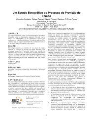
Figure 1: Teapot rendered with different relief textures using per-pixel lighting and self-shadowing.<br />
This paper presents a technique for mapping relief textures <strong>on</strong>to<br />
arbitrary polyg<strong>on</strong>al models in real time. In this approach, the mapping<br />
of the relief data is d<strong>on</strong>e in tangent space. As a result, it<br />
can be applied to polyg<strong>on</strong>al representati<strong>on</strong>s of curved surfaces producing<br />
correct self-occlusi<strong>on</strong>s, interpenetrati<strong>on</strong>s, shadows and perpixel<br />
lighting effects. The approach can be used to c<strong>on</strong>sistently add<br />
surface details to geometric models undergoing deformati<strong>on</strong>s, such<br />
as in the case of animated characters comm<strong>on</strong>ly found in games.<br />
The technique uses an inverse formulati<strong>on</strong> (i.e., pixel driven) based<br />
<strong>on</strong> an efficient ray-height-field intersecti<strong>on</strong> algorithm implemented<br />
<strong>on</strong> the GPU. It supports extreme close-up views of the surfaces,<br />
mip mapping and anisotropic texture filtering. Also, c<strong>on</strong>trary to<br />
high-dimensi<strong>on</strong>al representati<strong>on</strong>s of surface details, the low memory<br />
requirements of the proposed technique do not restrict its use to<br />
tiled textures.<br />
CR Categories: I.3.7 [Computer Graphics]: Three-Dimensi<strong>on</strong>al<br />
Graphics and <str<strong>on</strong>g>Real</str<strong>on</strong>g>ism<br />
Keywords: image-based rendering, relief mapping, moti<strong>on</strong> parallax,<br />
real-time rendering, surface details.<br />
1 Introducti<strong>on</strong><br />
Texture mapping [Catmull 1974] is a fundamental comp<strong>on</strong>ent of<br />
modern image synthesis systems, playing a major role in enhancing<br />
the realism of scenes. It adds significant amount of details to<br />
surfaces by simulating the appearance of different materials, the<br />
∗ e-mail:fabio@paralelo.com.br<br />
† e-mail:oliveira@inf.ufrgs.br<br />
‡ e-mail:comba@inf.ufrgs.br<br />
existence of surface wrinkles [Blinn 1978] or even by modifying<br />
the underlying geometric model [Cook 1984]. In recent years, a<br />
few texture mapping extensi<strong>on</strong>s have been introduced, for instance,<br />
for rendering texture appearance under different lighting orientati<strong>on</strong><br />
[Malzbender et al. 2001] and 3D surface details [Oliveira et al.<br />
2000]. <str<strong>on</strong>g>Relief</str<strong>on</strong>g> texture mapping [Oliveira et al. 2000] simulates the<br />
existence of 3D surface details using image warping techniques.<br />
Thus, correct views of geometrically rich objects can be obtained<br />
by rendering just a few textured polyg<strong>on</strong>s.<br />
Figure 2: Br<strong>on</strong>to’s tea hour. The surface details for the character,<br />
the teapot and the walls were rendered using relief mapping.<br />
In this paper, we show how relief textures can be mapped <strong>on</strong>to arbitrary<br />
polyg<strong>on</strong>al models by performing the mapping in tangent<br />
space [Peercy et al. 1997]. Figures 1 and 2 show several objects<br />
rendered with different surface details. These images also include<br />
per-pixel lighting and shadows cast by the surface relief. Compared<br />
to other recently proposed techniques to represent surface de-
tails [Wang et al. 2003; Wang et al. 2004], our approach presents<br />
several desirable features. In particular, it uses a much more compact<br />
representati<strong>on</strong>, is easy to implement, supports arbitrary closeup<br />
views without introducing noticeable texture distorti<strong>on</strong>s, and<br />
supports mip mapping and anisotropic texture filtering.<br />
The c<strong>on</strong>tributi<strong>on</strong>s of this paper include:<br />
• A technique for mapping relief textures <strong>on</strong>to arbitrary polyg<strong>on</strong>al<br />
models in real time (Secti<strong>on</strong> 3). The resulting renderings<br />
present correct self-occlusi<strong>on</strong>s, interpenetrati<strong>on</strong>s, shadows<br />
and per-pixel lighting. Moreover, it supports extreme<br />
close-up views of the added surface details;<br />
• An efficient algorithm for computing ray-height-field intersecti<strong>on</strong>s<br />
using programmable graphics hardware (Secti<strong>on</strong> 3);<br />
• A new relief texture representati<strong>on</strong> based <strong>on</strong> two depth layers<br />
(Secti<strong>on</strong> 4). Such a representati<strong>on</strong> significantly improves the<br />
rendering quality of single-depth-layer relief textures when<br />
mapped <strong>on</strong>to single polyg<strong>on</strong>s. This is achieved with no extra<br />
storage cost and small additi<strong>on</strong>al computati<strong>on</strong>al cost.<br />
2 Related Work<br />
Bump mapping [Blinn 1978] simulates the existence of surface details<br />
using normal perturbati<strong>on</strong>. Since the actual surface is not modified,<br />
self-occlusi<strong>on</strong>s, shadows and silhouettes are not accounted<br />
for. Horiz<strong>on</strong> maps [Max 1988] provide a soluti<strong>on</strong> for shadowing<br />
bump-mapped surfaces and can be implemented using the graphics<br />
hardware [Sloan and Cohen 2000]. An alternative soluti<strong>on</strong> that can<br />
also be implemented using hardware accelerati<strong>on</strong> was presented by<br />
Heidrich et al. [Heidrich et al. 2000].<br />
Displacement mapping [Cook 1984] changes the actual geometry<br />
of the underlying surface and as a result produces correct selfocclusi<strong>on</strong>s,<br />
shadows and silhouettes. Unfortunately, the use of<br />
displacement maps requires rendering a large number of micropolyg<strong>on</strong>s,<br />
which is undesirable for interactive applicati<strong>on</strong>s. In recent<br />
years, several approaches have been devised to accelerate the<br />
rendering of displacement maps and to avoid explicit rendering of<br />
micro-polyg<strong>on</strong>s. These approaches are based <strong>on</strong> ray tracing [Patters<strong>on</strong><br />
et al. 1991; Pharr and Hanrahan 1996; Heidrich and Seidel<br />
1998; Smits et al. 2000], 3D inverse image warping [Schaufler and<br />
Priglinger 1999] and 3D texture mapping [Meyer and Neyret 1998;<br />
Kautz and Seidel 2001]. The dem<strong>on</strong>strated ray-tracing and inversewarping-based<br />
approaches are computati<strong>on</strong>ally expensive and not<br />
appropriate for real-time applicati<strong>on</strong>s. The 3D-texture approaches<br />
render displacement maps as stacks of 2D texture-mapped polyg<strong>on</strong>s.<br />
This may introduce objecti<strong>on</strong>able artifacts depending <strong>on</strong> the<br />
viewing directi<strong>on</strong>. Hirche et al. [Hirche et al. 2004] use graphics<br />
hardware to ray cast displaced surfaces inside extruded tetrahedra<br />
and Gumhold [Gumhold 2003] implemented a pixel shader<br />
ray-caster to render ellipsoids.<br />
More recently, Wang et al. [Wang et al. 2003] presented a technique<br />
that pre-computes the distances from each displaced point to a reference<br />
surface. These distances are computed al<strong>on</strong>g many sampling<br />
viewing directi<strong>on</strong>s. The result is a five-dimensi<strong>on</strong>al functi<strong>on</strong> called<br />
a view-dependent displacement map (VDM) that can be queried at<br />
rendering time. Due to the large sizes of these datasets, VDMs<br />
need to be compressed before they can be stored in the graphics<br />
card memory. The compressi<strong>on</strong> is d<strong>on</strong>e using principal comp<strong>on</strong>ent<br />
analysis techniques. This approach works in real time and can produce<br />
nice results, but has some drawbacks: it introduces significant<br />
texture distorti<strong>on</strong>s and can <strong>on</strong>ly be applied to closed surfaces. Due<br />
to the large sizes of these representati<strong>on</strong>s, usually a single patch<br />
is created and tiled over the entire surface. Also, due to the precomputed<br />
resoluti<strong>on</strong> of these representati<strong>on</strong>s, they are intended for<br />
rendering from a certain distance and should not be used for closeup<br />
renderings.<br />
In order to reduce texture distorti<strong>on</strong>s and handle surfaces with<br />
boundaries, Wang et al. [Wang et al. 2004] introduced another fivedimensi<strong>on</strong>al<br />
representati<strong>on</strong> called GDM for rendering n<strong>on</strong>-heightfield<br />
structures. GDM also produces large sampling databases that<br />
need to be compressed. Likewise, GDMs are more appropriate for<br />
tiling and renderings from a certain distance.<br />
Parallax mapping [Kaneko et al. 2001] uses textures augmented<br />
with per-texel depth. In this approach, the texture coordinates al<strong>on</strong>g<br />
the view directi<strong>on</strong> are shifted based <strong>on</strong> the depth values using an<br />
approximate soluti<strong>on</strong>. While this technique can produce interesting<br />
results at very low cost, it is <strong>on</strong>ly appropriate for noisy irregular<br />
bumps, as the surfaces are inaccurately and dynamically deformed<br />
as the viewing positi<strong>on</strong> changes. No support for shadows has been<br />
dem<strong>on</strong>strated for parallax mapping.<br />
2.1 Review of <str<strong>on</strong>g>Relief</str<strong>on</strong>g> Texture <str<strong>on</strong>g>Mapping</str<strong>on</strong>g><br />
<str<strong>on</strong>g>Relief</str<strong>on</strong>g> texture mapping [Oliveira et al. 2000] uses image warping<br />
techniques and textures enhanced with per-texel depth to create the<br />
illusi<strong>on</strong> of complex geometric details when mapped <strong>on</strong>to flat polyg<strong>on</strong>s.<br />
The depth informati<strong>on</strong> is computed as the distance from a<br />
reference plane to the sampled surface. Figure 3 shows an example<br />
of a relief texture. On the left, <strong>on</strong>e sees a diffuse pre-shaded color<br />
texture with its corresp<strong>on</strong>ding depth data <strong>on</strong> the right.<br />
Figure 3: A relief texture: diffuse pre-shaded color (left) and depth<br />
map (right). In the depth map, dark means closer.<br />
Ideally, porti<strong>on</strong>s of a relief texture should <strong>on</strong>ly be warped <strong>on</strong> demand.<br />
However, the rendering of a height field is not as simple<br />
as c<strong>on</strong>venti<strong>on</strong>al texture mapping, requiring a search for the closest<br />
surface al<strong>on</strong>g any given viewing ray. In order to avoid this search,<br />
which tends to be computati<strong>on</strong>ally expensive, Oliveira et al. factored<br />
the mapping into a two-step process [Oliveira et al. 2000].<br />
First, the height field is c<strong>on</strong>verted into a regular 2D texture using a<br />
forward transformati<strong>on</strong>. Then, the resulting texture is mapped <strong>on</strong>to<br />
the polyg<strong>on</strong> in the c<strong>on</strong>venti<strong>on</strong>al way. Figure 4 compares the renderings<br />
produced by different techniques from the same viewpoint.<br />
In (a), the image was c<strong>on</strong>venti<strong>on</strong>ally texture-mapped <strong>on</strong>to a quadrilateral.<br />
Figure 4 (b) shows the result obtained when applying relief<br />
texture mapping to the same polyg<strong>on</strong>. For comparis<strong>on</strong>, Figure 4 (c)<br />
shows the color and depth data presented in Figure 3 rendered as a<br />
mesh of micro-polyg<strong>on</strong>s. Essentially, the results in (b) and (c) are<br />
indistinguishable from each other.<br />
Oliveira et al. [Oliveira et al. 2000] represented 3D objects by relief<br />
texture-mapping the visible faces of parallelepipeds. This situati<strong>on</strong><br />
is illustrated in Figure 5, where <strong>on</strong>e sees an object rendered as two
(a) (b) (c)<br />
Figure 4: Rendering comparis<strong>on</strong> from the same viewpoint. (a)<br />
Color image rendered as a c<strong>on</strong>venti<strong>on</strong>al texture. (b) <str<strong>on</strong>g>Relief</str<strong>on</strong>g> texture<br />
mapping rendering. (c) Rendering of the color and depth data in<br />
Figure 3 as a mesh of micro-polyg<strong>on</strong>s.<br />
relief texture-mapped polyg<strong>on</strong>s. The borders of the two polyg<strong>on</strong>s<br />
are shown <strong>on</strong> the left. This method, however, has not been extended<br />
to arbitrary surfaces. ElHew and Yang [ElHelw and Yang 2003]<br />
used cylindrical versi<strong>on</strong>s of relief textures (i.e., cylindrical images<br />
with depth measured al<strong>on</strong>g the normal directi<strong>on</strong>s to the cylinder)<br />
to render images of endoscopic simulati<strong>on</strong>s. They create insidelooking-outside<br />
renditi<strong>on</strong>s by warping the cylindrical textures according<br />
the the viewer’s positi<strong>on</strong> and by texture-mapping the result<br />
<strong>on</strong>to a reference cylinder. Their technique cannot be generalized to<br />
arbitrary surfaces.<br />
Figure 5: 3D objects are rendered by relief texture-mapping the visible<br />
faces of a parallelepiped. Object rendered showing the borders<br />
of the quads (left) and without borders (right).<br />
3 <str<strong>on</strong>g>Relief</str<strong>on</strong>g> <str<strong>on</strong>g>Mapping</str<strong>on</strong>g> <strong>on</strong> Polyg<strong>on</strong>al <strong>Surfaces</strong><br />
We exploit the programmability of modern graphics hardware to<br />
effectively render surface details <strong>on</strong>to arbitrary polyg<strong>on</strong>al surfaces.<br />
Since the rendering is performed using fragment shaders, we can<br />
also perform per-pixel shading and compute shadows. Thus, the<br />
color texture originally used to store pre-computed diffuse shading<br />
can be discarded and replaced by a normal map. Any 2D texture can<br />
be mapped <strong>on</strong>to the resulting representati<strong>on</strong>. Figure 6 shows a relief<br />
texture represented by its corresp<strong>on</strong>ding depth and normal maps.<br />
The depth map is quantized and represented using the alpha channel<br />
of the RGBα texture used to store the normal map. This way, a<br />
single 32-bit per texel texture suffices to represent the structure of a<br />
relief texture.<br />
We normalize the height values to the [0,1] range. Figure 7 shows<br />
the representati<strong>on</strong> (cross-secti<strong>on</strong>) of such a height-field surface.<br />
Figure 6: A relief texture represented by a depth (left) and a normal<br />
map (right). The normals are mapped to the [0,1] range and stored<br />
as an RGB image.<br />
From top to bottom, the depth values vary from 0.0 to 1.0.<br />
The process of mapping relief data to a polyg<strong>on</strong>al surface can be<br />
c<strong>on</strong>ceptually understood as following. For each fragment to be rendered:<br />
• compute the viewing directi<strong>on</strong> (VD) as the vector from the<br />
viewer to the 3D positi<strong>on</strong> of the point <strong>on</strong> the polyg<strong>on</strong>al surface;<br />
• transform VD to the tangent space (defined by the tangent,<br />
normal and bi-normal vectors) associated with the current<br />
fragment;<br />
• use VD’ (the transformed VD) and A, the (s,t) texture coordinates<br />
of the fragment, to compute B, the (u,v) texture coordinates<br />
where the ray reaches the depth value 1.0 (see Figure 7);<br />
• compute the intersecti<strong>on</strong> between VD’ and the height-field<br />
surface using a binary search starting with A and B;<br />
• perform the shading of the fragment using the attributes (e.g.,<br />
normal, depth, color, etc.) associated with the texture coordinates<br />
of the computed intersecti<strong>on</strong> point.<br />
This process is illustrated in Figure 7. Point A has an associated<br />
depth equal to zero, while B has depth equal to 1.0. At each step,<br />
<strong>on</strong>e computes the midpoint of the current interval and assigns it<br />
the average depth and texture coordinates of the endpoints. In the<br />
example shown in Figure 7, the circle marked ”1” represents the<br />
first midpoint. The averaged texture coordinates are used to access<br />
the depth map. If the stored depth is smaller than the computed<br />
<strong>on</strong>e, the point al<strong>on</strong>g the ray is inside the height field surface, as in<br />
the case of point 1 in Figure 7. The binary search proceeds with<br />
<strong>on</strong>e endpoint inside and other outside the surface. In the example<br />
shown in Figure 7, the numbers indicate the order in which the midpoints<br />
are obtained. In practice, we have found that eight steps of<br />
binary subdivisi<strong>on</strong> is sufficient to produce very satisfactory results.<br />
This is equivalent to subdivide the depth range of the height field<br />
in 2 8 = 256 equally spaced intervals. Other researchers have used<br />
64 axis-aligned equally-spaced 2D texture slices to render displacement<br />
maps using 3D textures [Meyer and Neyret 1998; Kautz and<br />
Seidel 2001]. The reader should also notice that our approach takes<br />
advantage of texture interpolati<strong>on</strong>. Thus, while in techniques based<br />
<strong>on</strong> 3D texture mapping <strong>on</strong>e may see in between slices, our technique<br />
does not suffer from this problem. As the depth map is treated<br />
and accessed as a texture, texture filtering (e.g., bilinear) guarantees<br />
that the height-field surface will be c<strong>on</strong>tinuous. As a result, the proposed<br />
technique can be used to produce extreme close-up views of<br />
the surface without noticeable artifacts (see Figures 16 and 17).<br />
The binary search procedure just described may lead to incorrect<br />
results if the viewing ray intersects the height field surfaces in more<br />
than <strong>on</strong>e point, as illustrated in Figure 8. In this example, the depth<br />
value associated with the first midpoint has a depth value smaller
Figure 7: Ray intersecti<strong>on</strong> with a height-field surface using binary<br />
search. Starting with A and B, the numbers indicate the sequence<br />
of computed midpoints.<br />
than the <strong>on</strong>e retrieved from the depth map. Since the point is above<br />
the height field surface, the binary search would c<strong>on</strong>tinue its way<br />
going deeper into the bounding box and find point 3 as the intersecti<strong>on</strong>,<br />
which is clearly incorrect. In order to avoid missing the first<br />
intersecti<strong>on</strong>, we start the process with a linear search. Beginning<br />
at point A, we step al<strong>on</strong>g the AB line at increments of δ times the<br />
length of AB looking for the first point inside the surface (Figure 9).<br />
If the graphics card supports shading model 3.0, δ varies from fragment<br />
to fragment as functi<strong>on</strong> of the angle between VD’ and the<br />
interpolated surface normal at the fragment. As this angle grows,<br />
the value of δ decreases. In our current implementati<strong>on</strong>, no more<br />
than 32 steps are taken al<strong>on</strong>g the segment AB. Notice that since<br />
the linear search does not involve any dependent texture accesses,<br />
this process is very fast as we can make several texture fetches in<br />
parallel.<br />
Figure 8: Problem with binary search. The midpoint between A and<br />
B is outside the height-field surface but the viewing ray has already<br />
pierced the surface.<br />
Once the first point under the height field surface has been identified,<br />
the binary search starts using the last point outside the surface<br />
and current <strong>on</strong>e. In this case, a smaller number of binary subdivisi<strong>on</strong>s<br />
is needed. For example, if the depth interval between two linearly<br />
searched points is 1/8, a six-step binary search will be equivalent<br />
to subdividing the interval into 512 (2 3 × 2 6 ) equally spaced<br />
intervals.<br />
3.1 Surface Self-Shadowing<br />
Rendering shadows is a visibility problem [Williams 1978]. Therefore,<br />
a similar procedure can be used to determine whether a frag-<br />
Figure 9: Linear search, from A to B, for the first point inside the<br />
height-field surface.<br />
ment is lit or in shade. In this case, we check if the light ray intersects<br />
the height-field surface between point C and the actual point<br />
being shaded (Figure 10). In case an intersecti<strong>on</strong> exists, the point<br />
must be in shade. Notice that there is no need to find the actual intersecti<strong>on</strong><br />
point, but simply decide whether such an intersecti<strong>on</strong> exists,<br />
which can also be d<strong>on</strong>e using a similar strategy. Figure 14 and 19(c)<br />
show examples of relief renderings c<strong>on</strong>taining self-shadowing.<br />
Figure 10: Shadow computati<strong>on</strong>. One needs to decide if the light<br />
ray intersects the height-field surface between point C and the point<br />
where the viewing ray first hits the surface.<br />
4 Dual-Depth <str<strong>on</strong>g>Relief</str<strong>on</strong>g> Textures<br />
This secti<strong>on</strong> introduces an extensi<strong>on</strong> to relief textures that uses two<br />
layers of depth informati<strong>on</strong>. Such an extensi<strong>on</strong>, called dual-depth<br />
relief textures, can be used to produce approximate representati<strong>on</strong>s<br />
for opaque, closed-surface objects using <strong>on</strong>ly <strong>on</strong>e relief-mapped<br />
polyg<strong>on</strong>.<br />
Figure 11: Dual-depth relief textures. The combined use of fr<strong>on</strong>t<br />
and back depth layers produces tight bounds for an object representati<strong>on</strong>.
As <strong>on</strong>e tries to sample an object using a single relief texture, not<br />
enough informati<strong>on</strong> will be available to produce a proper rec<strong>on</strong>structi<strong>on</strong>.<br />
In particular, no informati<strong>on</strong> will exist about what lays<br />
behind the object (Figure 11 left). In these cases, inverse rendering<br />
techniques may extend the ends of these surfaces forming<br />
“skins” [McMillan 1997]. The occurrence of skins can be eliminated<br />
with the use of <strong>on</strong>e extra layer of depth that represents the<br />
back of the object (Figure 11 (center)). The combined effect of the<br />
two depth layers produces a much tighter boundary for the object<br />
(Figure 11 (right)) and leads to better quality renderings.<br />
Notice that this representati<strong>on</strong> is not exactly a layered-depth image<br />
(LDI) [Shade et al. 1998]: the two layers of depth are computed<br />
as orthographic distances measured with respect to <strong>on</strong>e of the<br />
faces of the depth bounding box and it does not store color informati<strong>on</strong>.<br />
Moreover, the sec<strong>on</strong>d depth layer is not used directly for<br />
rendering, but for c<strong>on</strong>straining the search for ray-height-field intersecti<strong>on</strong>s.<br />
Like other impostor techniques, this representati<strong>on</strong> is not<br />
intended to be seen from arbitrary viewpoints. However, we show<br />
that they can be used for quite large range of angles.<br />
The two depth maps and the normals can be stored in a single texture.<br />
Since all normals are unit length, we can store <strong>on</strong>ly the x and<br />
y comp<strong>on</strong>ents in the normal map, using the other two channels to<br />
represent the two depth layers. The z comp<strong>on</strong>ent of the normal can<br />
be recovered in the shader as z = 1 − (x 2 + y 2 ). Figure 12 shows<br />
dual-depth maps for two models: angel (top) and Christ (bottom).<br />
The depth values of both layers are defined with respect to the same<br />
reference plane. In Figure 12, the maps <strong>on</strong> the left represent the<br />
fr<strong>on</strong>t of the object, while the <strong>on</strong>es <strong>on</strong> the right represent the back<br />
surface. The rendering process using two depth layers is similar to<br />
what was described in Secti<strong>on</strong> 3. In this case, however, a point is<br />
c<strong>on</strong>sidered inside the represented object if fr<strong>on</strong>t depth ≤ point depth<br />
≤ back depth.<br />
(a) (b)<br />
(c) (d)<br />
Figure 12: Dual-depth maps. Fr<strong>on</strong>t (left) and back (right) layers.<br />
The top row samples an angel model. The bottom row is the sampling<br />
of a Christ model.<br />
Figure 13 compares the renderings of the sampled objects shown in<br />
Figure 12 using single and dual-depth relief textures. In the case<br />
of single, <strong>on</strong>ly the fr<strong>on</strong>t depth was used. In all cases, the images<br />
were created by rendering a single texture-mapped polyg<strong>on</strong>. On<br />
the left, <strong>on</strong>e sees the renderings produced with the use of a single<br />
depth layer. Notice the existence of skins <strong>on</strong> the angel’s hair and<br />
over its right wing, and <strong>on</strong> Christ’s hair and silhouettes. The Christ<br />
image was cropped to focus <strong>on</strong> some details.<br />
(a) (b)<br />
(c) (d)<br />
Figure 13: Renderings produced using single (left) and dual-depth<br />
(right) relief textures. Notice the existence of skins <strong>on</strong> the left images,<br />
which are not present in the right <strong>on</strong>es. A 2D wooden texture<br />
was added to the models.<br />
5 Results<br />
We have implemented the techniques described in the paper as fragment<br />
programs written in Cg and used them to map surface details<br />
to several polyg<strong>on</strong>al objects. The mapping process is straightforward,<br />
using the texture coordinates and the tangent, normal and<br />
binormal vectors associated to the vertices of the model. Except for<br />
the rock relief texture used to render Br<strong>on</strong>to, the character shown<br />
in Figures 2 and 15, and the teapots in Figures 1 (right) and 17, all<br />
textures used in the paper were 512x512 RGBα textures. This includes<br />
the dual-depth relief representati<strong>on</strong>s. The st<strong>on</strong>e texture used<br />
for Br<strong>on</strong>to was a 256x256 texture. The depth maps were quantized<br />
using 8 bits per texel. The quantized values represent evenly spaced<br />
depths, which can be scaled during the rendering using a parameter<br />
of the shader. All scenes were rendered at a resoluti<strong>on</strong> of 800x600<br />
pixels at 85 frames per sec<strong>on</strong>d, which is the refresh rate of our m<strong>on</strong>itor.<br />
These measurements were made <strong>on</strong> a 3 GHz PC with 512 MB<br />
of memory using a GeForce FX6800 GT with 256 MB of memory.<br />
Figure 1 shows the Utah teapot rendered using three different relief<br />
textures with per-pixel shading and shadows. Figure 2 shows a<br />
scene where all surfaces details for the character, the teapot and the<br />
brick walls were produced using relief mapping. The relief mapped<br />
objects naturally integrate themselves with the other elements of the<br />
scene. Notice the shadows <strong>on</strong> the teapot, which are cast by its own<br />
relief. Figure 14 shows a closer view of the same teapot, where all<br />
the surface details can be appreciated. Notice the correct shadows<br />
and occlusi<strong>on</strong>s due to parallax. The relief used for the teapot was<br />
obtained from the depth map shown in Figure 3.<br />
Figure 15 shows another view of Br<strong>on</strong>to with its st<strong>on</strong>e texture. Note<br />
how the texture correctly adjusts itself to the polyg<strong>on</strong>al surface, producing<br />
a very realistic look. The relief details are emphasized by<br />
the per-pixel lighting.<br />
Figure 19 compares the renderings of a single polyg<strong>on</strong> with the data<br />
shown in Figure 6 using three different techniques. This height field<br />
c<strong>on</strong>tains both smooth and sharp features and tests the ability of the
Figure 14: A close view of the same teapot from the scene shown<br />
in Figure 2. Note the shadows. The relief used for the teapot was<br />
obtained from the depth map shown in Figure 3.<br />
Figure 15: Br<strong>on</strong>to, a game character rendered using relief mapping.<br />
techniques to correctly represent surface details. The images were<br />
created from the same viewpoint using: (a) bump mapping, (b) parallax<br />
mapping and (c) relief mapping with self-shadowing. Notice<br />
how relief mapping succeeds in producing a correct image for this<br />
object, while both bump and parallax mapping fail. The images<br />
produced by these techniques present some flatening. In Figure 19<br />
(c) <strong>on</strong>e can also observe the shadows properly cast by the surface<br />
relief. The accompanying videos provide some more examples of<br />
scenes c<strong>on</strong>taining shadows and per-pixel lighting recorded in real<br />
time.<br />
Figure 16 and 17 show two extreme close-ups of relief mapped<br />
surfaces. The resoluti<strong>on</strong>s of the textures used to produce these<br />
renderings are 512x512 and 256x256, respectively. Notice how<br />
sharp these close-up images are. Correct interpenetrati<strong>on</strong> of reliefmapped<br />
surfaces (e.g., involving multiple relief-textured objects)<br />
can be achieved by appropriately modulating the Z-buffer. The 3D<br />
coordinates associated with a fragment corresp<strong>on</strong>ding to the polyg<strong>on</strong>al<br />
surface are available to the fragment program. From this, we<br />
can compute the 3D positi<strong>on</strong> of the intersected point at the surface<br />
height field. We then compute its corresp<strong>on</strong>ding depth value to test<br />
and/or update the Z-buffer. Figure 18 shows a relief mapped surface<br />
interpenetrated by three textured spheres. Notice the correct<br />
interpenetrati<strong>on</strong> boundaries.<br />
Figure 16: <str<strong>on</strong>g>Relief</str<strong>on</strong>g> texture-mapped teapot (top). Close-up view produced<br />
with a 512x512 st<strong>on</strong>e relief texture (bottom).<br />
If a feature represented by a height field is too thin, it might be<br />
possible that the linear search misses it. This is an aliasing problem<br />
for which there is no perfect soluti<strong>on</strong>. In practice, although we have<br />
modeled and rendered sharp features, we have not encountered such<br />
artifacts.<br />
Since we use mip mapping [Williams 1983], texture minificati<strong>on</strong><br />
causes the resampling of the height-field surface to be d<strong>on</strong>e <strong>on</strong> a<br />
filtered versi<strong>on</strong> of the depth map. While this is not strictly correct,<br />
it saves us the need to create a separate versi<strong>on</strong> of the depth map<br />
for each level of the mip map (which would then have to be interpolated<br />
anyway) and helps to reduce animati<strong>on</strong> aliasing artifacts. It<br />
also improves rendering performance, as the use of smaller textures<br />
tends to increase cache coherence.<br />
6 C<strong>on</strong>clusi<strong>on</strong><br />
We have presented a technique for mapping relief textures <strong>on</strong>to arbitrary<br />
polyg<strong>on</strong>al models in real time. The mapping is d<strong>on</strong>e in tangent<br />
space [Peercy et al. 1997], guaranteeing its generality and applicability<br />
to deforming surfaces. The technique produces correct<br />
self-occlusi<strong>on</strong>s, interpenetrati<strong>on</strong>s, shadows and all standard perpixel<br />
lighting and filtering effects. We also described an efficient<br />
algorithm for finding the intersecti<strong>on</strong> between a ray and a height<br />
field based <strong>on</strong> binary search. Since the depth maps representing the<br />
heights undergo texture filtering, the resampled height-field surface<br />
is c<strong>on</strong>tinuous, allowing the user to obtain extreme close-up views of<br />
the surface details. The compactness and ease of implementati<strong>on</strong> of<br />
the presented technique make it an attractive alternative for games.<br />
We have also extended relief textures with dual-depth maps. This<br />
new representati<strong>on</strong> allows for approximate representati<strong>on</strong>s of 3D<br />
objects using a single texture. Renderings of these objects can be
(a) (b) (c)<br />
Figure 19: One polyg<strong>on</strong> rendered from the same viewpoint using three different techniques: (a) Bump mapping, (b) Parallax mapping and (c)<br />
<str<strong>on</strong>g>Relief</str<strong>on</strong>g> mapping with self-shadowing. A 2D wooden texture was mapped to the surface.<br />
Figure 17: <str<strong>on</strong>g>Relief</str<strong>on</strong>g> texture-mapped teapot (top). Close-up view produced<br />
with a 256x256 rock relief texture (bottom).<br />
generated rendering a single polyg<strong>on</strong>, while producing dynamic impostors<br />
that can be used for a c<strong>on</strong>siderable angular range.<br />
Our current implementati<strong>on</strong> still does not add details to the underlying<br />
object’s silhouette. This is a valuable feature to enhance realism<br />
and we are exploring ways of changing the silhouettes to correctly<br />
represent these details.<br />
References<br />
BLINN, J. F. 1978. Simulati<strong>on</strong> of wrinkled surfaces. In Proceedings<br />
of the 5th annual c<strong>on</strong>ference <strong>on</strong> Computer graphics and interactive<br />
techniques, ACM Press, 286–292.<br />
CATMULL, E. 1974. A Subdivisi<strong>on</strong> Algorithm for Computer Display<br />
of Curved <strong>Surfaces</strong>. PhD thesis, University of Utah, Salt<br />
Lake City, Utah.<br />
COOK, R. L. 1984. Shade trees. In Proceedings of the 11th<br />
annual c<strong>on</strong>ference <strong>on</strong> Computer graphics and interactive techniques,<br />
ACM Press, 223–231.<br />
ELHELW, M. A., AND YANG, G.-Z. 2003. Cylindrical relief<br />
texture mapping. Journal of WSCG 11 (feb).<br />
Figure 18: Interpenetrati<strong>on</strong> am<strong>on</strong>g a relief mapped surface and<br />
some textured spheres. Notice the correct boundaries.<br />
GUMHOLD, S. 2003. Splatting illuminated ellipsoids with depth<br />
correcti<strong>on</strong>. In 8th Internati<strong>on</strong>al Fall Workshop <strong>on</strong> Visi<strong>on</strong>, Modelling<br />
and Visualizati<strong>on</strong>, 245–252.<br />
HEIDRICH, W., AND SEIDEL, H.-P. 1998. Ray-tracing procedural<br />
displacement shaders. In Graphics Interface, 8–16.<br />
HEIDRICH, W., DAUBERT, K., KAUTZ, J., AND SEIDEL, H.-P.<br />
2000. Illuminating micro geometry based <strong>on</strong> precomputed visibility.<br />
In Siggraph 2000, Computer Graphics Proc., 455–464.<br />
HIRCHE, J., EHLERT, A., GUTHE, S., AND DOGGETT, M.<br />
2004. Hardware accelerated per-pixel displacement mapping.<br />
In Graphics Interface, 153 – 158.<br />
KANEKO, T., TAKAHEI, T., INAMI, M., KAWAKAMI, N.,<br />
YANAGIDA, Y., MAEDA, T., AND TACHI:, S. 2001. Detailed<br />
shape representati<strong>on</strong> with parallax mapping. In Proceedings of<br />
the ICAT 2001, 205–208.<br />
KAUTZ, J., AND SEIDEL, H.-P. 2001. Hardware accelerated displacement<br />
mapping for image based rendering. In Proceedings<br />
of Graphics Interface 2001, 61–70.<br />
MALZBENDER, T., GELB, D., AND WOLTERS, H. 2001. Polynomial<br />
texture maps. In Siggraph 2001, Computer Graphics Proceedings,<br />
519–528.<br />
MAX, N. 1988. Horiz<strong>on</strong> mapping: shadows for bump-mapped<br />
surfaces. The Visual Computer 4, 2, 109–117.<br />
MCMILLAN, L. 1997. An Image-Based Approach to Three-<br />
Dimensi<strong>on</strong>al Computer Graphics. PhD thesis, University of<br />
North Carolina at Chapel Hill, Chapel Hill, NC.<br />
MEYER, A., AND NEYRET, F. 1998. Interactive volumetric textures.<br />
In Eurographics Rendering Workshop 1998, 157–168.
OLIVEIRA, M. M., BISHOP, G., AND MCALLISTER, D. 2000.<br />
<str<strong>on</strong>g>Relief</str<strong>on</strong>g> texture mapping. In Siggraph 2000, Computer Graphics<br />
Proceedings, 359–368.<br />
PATTERSON, J., HOGGAR, S., AND LOGIE, J. 1991. Inverse<br />
displacement mapping. Comp. Graphics Forum 10, 2, 129–139.<br />
PEERCY, M., AIREY, J., AND CABRAL, B. 1997. Efficient bump<br />
mapping hardware. In SIGGRAPH ’97, 303–306.<br />
PHARR, M., AND HANRAHAN, P. 1996. Geometry caching<br />
for ray-tracing displacement maps. In Eurographics Rendering<br />
Workshop 1996, Springer Wien, 31–40.<br />
SCHAUFLER, G., AND PRIGLINGER, M. 1999. Efficient displacement<br />
mapping by image warping. In Eurographics Rendering<br />
Workshop 1998, Springer Wein, 175–186.<br />
SHADE, J. W., GORTLER, S. J., HE, L.-W., AND SZELISKI, R.<br />
1998. Layered depth images. In Siggraph 1998, Computer<br />
Graphics Proceedings, 231–242.<br />
SLOAN, P.-P. J., AND COHEN, M. F. 2000. Interactive horiz<strong>on</strong><br />
mapping. In Proceedings of the Eurographics Workshop <strong>on</strong> Rendering<br />
Techniques 2000, Springer-Verlag, 281–286.<br />
SMITS, B. E., SHIRLEY, P., AND STARK, M. M. 2000. Direct<br />
ray tracing of displacement mapped triangles. In Proceedings<br />
of the Eurographics Workshop <strong>on</strong> Rendering Techniques 2000,<br />
Springer-Verlag, 307–318.<br />
WANG, L., WANG, X., TONG, X., LIN, S., HU, S., GUO, B.,<br />
AND SHUM, H.-Y. 2003. View-dependent displacement mapping.<br />
ACM Trans. Graph. 22, 3, 334–339.<br />
WANG, X., TONG, X., LIN, S., HU, S., GUO, B., AND SHUM,<br />
H.-Y. 2004. Generalized displacement maps. In Eurographics<br />
Symposium <strong>on</strong> Rendering 2004, EUROGRAPHICS, 227–233.<br />
WILLIAMS, L. 1978. Casting curved shadows <strong>on</strong> curved surfaces.<br />
In Siggraph 1978, Computer Graphics Proceedings, 270–274.<br />
WILLIAMS, L. 1983. Pyramidal parametrics. In SIGGRAPH ’83:<br />
Proceedings of the 10th annual c<strong>on</strong>ference <strong>on</strong> Computer graphics<br />
and interactive techniques, ACM Press, 1–11.<br />
Appendix: Fragment Shaders in Cg<br />
f2s main frag relief( v2f IN,<br />
uniform sampler2D rmtex:TEXUNIT0, // rm texture map<br />
uniform sampler2D colortex:TEXUNIT1, // color texture map<br />
uniform float4 lightpos, // light positi<strong>on</strong> in view space<br />
uniform float4 ambient, // ambient color<br />
uniform float4 diffuse, // diffuse color<br />
uniform float4 specular, // specular color<br />
uniform float2 planes, // near and far planes info<br />
uniform float tile, // tile factor<br />
uniform float depth) // scale factor for height-field depth<br />
{<br />
f2s OUT;<br />
float4 t,c; float3 p,v,l,s; float2 dp,ds,uv; float d;<br />
// ray intersect in view directi<strong>on</strong><br />
p = IN.vpos; // pixel positi<strong>on</strong> in eye space<br />
v = normalize(p); // view vector in eye space<br />
// view vector in tangent space<br />
s = normalize(float3(dot(v,IN.tangent.xyz),<br />
dot(v,IN.binormal.xyz),dot(IN.normal,-v)));<br />
// size and start positi<strong>on</strong> of search in texture space<br />
ds = s.xy*depth/s.z;<br />
dp = IN.texcoord*tile;<br />
// get intersecti<strong>on</strong> distance<br />
d = ray intersect rm(rmtex,dp,ds);<br />
// get normal and color at intersecti<strong>on</strong> point<br />
uv=dp+ds*d;<br />
t=tex2D(rmtex,uv);<br />
c=tex2D(colortex,uv);<br />
t.xyz=t.xyz*2.0-1.0; // expand normal to eye space<br />
t.xyz=normalize(t.x*IN.tangent.xyz+<br />
t.y*IN.binormal.xyz+t.z*IN.normal);<br />
// compute light directi<strong>on</strong><br />
p += v*d*s.z;<br />
l=normalize(p-lightpos.xyz);<br />
#ifdef RM DEPTHCORRECT<br />
// planes.x=-far/(far-near); planes.y =-far*near/(far-near);<br />
OUT.depth=((planes.x*p.z+planes.y)/-p.z);<br />
#endif<br />
// compute diffuse and specular terms<br />
float att=saturate(dot(-l,IN.normal));<br />
float diff=saturate(dot(-l,t.xyz));<br />
float spec=saturate(dot(normalize(-l-v),t.xyz));<br />
float4 finalcolor=ambient*c;<br />
#ifdef RM SHADOWS<br />
// ray intersect in light directi<strong>on</strong><br />
dp+= ds*d; // update positi<strong>on</strong> in texture space<br />
// light directi<strong>on</strong> in texture space<br />
s = normalize(float3(dot(l,IN.tangent.xyz),<br />
dot(l,IN.binormal.xyz),dot(IN.normal,-l)));<br />
ds = s.xy*depth/s.z;<br />
dp-= ds*d; // entry point for light ray in texture space<br />
// get intresecti<strong>on</strong> distance from light ray<br />
float dl = ray intersect rm(rmtex,dp,ds.xy);<br />
if (dl0.996) // if no depth found yet<br />
if (depth ≥ t.w)<br />
best depth=depth; // store best depth<br />
}<br />
depth=best depth;<br />
// search around first point (depth) for closest match<br />
for ( int i=0; i