Catalog V11 Automotive-03:V10-englisch.qxd - Ludwig Hunger
Catalog V11 Automotive-03:V10-englisch.qxd - Ludwig Hunger
Catalog V11 Automotive-03:V10-englisch.qxd - Ludwig Hunger

You also want an ePaper? Increase the reach of your titles
YUMPU automatically turns print PDFs into web optimized ePapers that Google loves.
<strong>Catalog</strong> <strong>V11</strong><br />
Tools and Equipment<br />
for <strong>Automotive</strong> Workshops<br />
<strong>Ludwig</strong> <strong>Hunger</strong> GmbH<br />
Mailing address: Office address:<br />
Postfach 70 09 60 Gräfelfinger Str. 146 Fax +49 89 7091 26<br />
81309 München 81375 München Tel. +49 89 7091 0<br />
Germany Germany<br />
E-mail: info@ludwig-hunger de<br />
www.ludwig-hunger.de
- 2 -<br />
Experience<br />
Performance<br />
Quality<br />
HUNGER - a company with experience - specializing in the<br />
manufacture of precision tools and valve service equipment<br />
for many years - and with the most comprehensive range of<br />
valve service equipment.<br />
Years ago, HUNGER pioneered precision valve and valve<br />
seat refacing systems which have been further developed<br />
and refined until we have the present high performance<br />
equipment.<br />
The qualities of HUNGER equipment are derived from working<br />
in very close cooperation with leading engine manufacturers<br />
and the research and experience gained by HUN-<br />
GER in over 60 years of precision equipment manufacture.<br />
HUNGER equipment has been tested and approved by leading<br />
engine manufacturers and is being used for high performance<br />
work throughout the world. Today´s exacting tolerances<br />
and finishes call for HUNGER equipment.<br />
You can rely on HUNGER.<br />
HUNGER manufactures also a comprehensive range of<br />
valve and valve seat refacing machines for servicing the<br />
valves and valve seats of large marine and stationary diesel<br />
engines.<br />
Please feel free to ask for further information
<strong>Catalog</strong> <strong>V11</strong> - 3 -<br />
Contents<br />
Page<br />
<strong>Hunger</strong> Valve Seat Refacing 4<br />
Valve Seat Refacing Tools:<br />
Type VDS1A for Seats from 14 to 60 mm diam. 5 - 18<br />
Parts - Accessories 6 - 7<br />
Sets 8<br />
Pilots Series VD1 9 - 10<br />
Cutters 11 - 18<br />
Type VDS2 for Seats from 30 to 90 mm diam. 19 - 21<br />
Parts - Accessories - Sets 18<br />
Pilots Series VD2 20<br />
Cuttersl 21 - 22<br />
Type VD2 for Seats from 30 to 90 mm diam. 23 - 25<br />
Parts - Accessories - Sets 24 - 25<br />
Steady<br />
Counterboring Tool:<br />
26<br />
Type RDS1 29 - 32<br />
Parts - Accessories 30 - 31<br />
Cutters for RDS1<br />
Seating Refacing Tool<br />
32<br />
BDW Refacing Tool for the cylinder liner seating<br />
Cylinder Head Stand<br />
33<br />
K2000 Cylinder Head Stand<br />
Valve Refacing Machines<br />
34 - 35<br />
VKS 16 Valve Grinding Machine 36 - 37<br />
VKM 1A Valve Grinding Machine 38 - 39<br />
Valve Guide Tool Kit 40 - 41<br />
Checking Equipment<br />
Valve Guide Reamers<br />
42<br />
Expanding Valve Guide Reamers Type V 43 - 44<br />
Solid Valve Guide Reamers Type VR 45<br />
Expanding Reamers for Workshops<br />
Expanding Reamers Type D 46<br />
Expanding Reamers Type E 47<br />
Expanding Reamers Type Typ K 48<br />
Expanding Reamers Type Typ U 49-50<br />
Expanding Shell Reamers Type Type H 51<br />
Tool Bars and Tool Bar Guides 52<br />
Align Reaming and Boring 53<br />
Supporting Fixture for Tool Bars 54<br />
Boring Heads - Feed Devices 55
- 4 - <strong>Hunger</strong> Valve Seat Refacing<br />
Details<br />
The <strong>Hunger</strong> Valve Seat Refacing Method,<br />
the superior alternative to grinding and form cutting.<br />
Working Principle:<br />
The <strong>Hunger</strong> VD refaces the valve seat in<br />
a lathe-type facing action.<br />
The valve seat is refaced to the preset<br />
depth by the simultaneous application of<br />
both a rotary and a transverse feed motion<br />
to the single point carbide cutter.<br />
While the single point carbide cutter rotates<br />
in a circle around the valve seat, a<br />
feed gear mechanism ensures a continuous<br />
outward transverse feed motion<br />
under the proper seat angle.<br />
This angle is defined by an inclined slideway<br />
in the exchangeable adapter head.<br />
<strong>Hunger</strong> machining eliminates the high<br />
and low spots normal to surface grinding<br />
or form cutting.<br />
Handling:<br />
Operation is straightforward.<br />
No setting gauges, no time consuming<br />
measurements or guesswork when mounting<br />
the cutter and setting up the VD on<br />
pilot.<br />
First, lock the pilot in the valve guide.<br />
Then lower VD over the pilot and position<br />
the cutter in front of the inner edge of the<br />
valve seat.<br />
Turn micrometer infeed to set the desired<br />
depth of cut.<br />
Rotate VD with handle to reface the valve<br />
seat in a lathe-type refacing action.<br />
Advantages:<br />
The <strong>Hunger</strong> VD refaces the valve seat in<br />
flawless concentric patterns, providing the<br />
best surface texture for a complete valve<br />
seal.<br />
The <strong>Hunger</strong> VD refaces all types of seats<br />
within a very broad diameter range.<br />
Carbide tipped cutters or cutters with<br />
indexable carbide insert handle seat materials<br />
from cast iron to stellite.<br />
Cutters are availabe for both seat refacing<br />
and seat narrowing by machining an outer<br />
and/ or inner correction with the primary<br />
and/or secondary cutting edge.<br />
All carbide tipped cutters can be resharpened<br />
on standard tool sharpeners.<br />
Roundness, concentricity and surface finish<br />
of the refaced seat are within manufacturers´<br />
secifications.
Capacity:<br />
Valve seat diameter range 14 - 60mm<br />
Valve seat angles 45°, 35°. 30°,<br />
25°, 20°, 15° & 0°<br />
VDS1A - 5 -<br />
Valve Seat Refacing Tool<br />
The universal tool system<br />
for refacing valve seats<br />
from 14 to 60mm diam.<br />
Application:<br />
Motorcycles<br />
Cars<br />
Light commercial vehicles
- 6 - VDS1A<br />
Parts and Accessories<br />
Item. Description Part No.<br />
1. VDS1A Basic Unit<br />
The gear head of the basic unit is designed to receive an<br />
adapter head for the respective seat angle.<br />
2. Adapter Heads<br />
Each adapter head includes a tool slide which is guided under<br />
an angle corresponding to the valve seat angle.<br />
234 11 002<br />
D1/45 Adapter Head for 45° seat angle 234 11 120<br />
D1/35 Adapter Head for 35° seat angle 234 14 120<br />
D1/30 Adapter Head for 30° seat angle 234 12 120<br />
D1/25 Adapter Head for 25° seat angle 234 15 120<br />
D1/20 Adapter Head for 20° seat angle 234 17 120<br />
D1/15 Adapter Head for 15° seat angle 234 13 120<br />
D1/0 Adapter Head for 0° angle<br />
Complete Refacing Units:<br />
consisting of basic unit and mounted adapter head<br />
234 19 120<br />
VDS 1A/45 Refacing Unit for 45° seat angle 236 21 000<br />
VDS 1A/35 Refacing Unit for 35° seat angle 236 24 000<br />
VDS 1A/30 Refacing Unit for 30° seat angle 236 22 000<br />
VDS 1A/20 Refacing Unit for 25° seat angle 236 25 000<br />
VDS 1A/20 Refacing Unit for 20° seat angle 236 27 000<br />
VDS 1A/15 Refacing Unit for 15° seat angle 236 23 000<br />
VDS 1A/0 Refacing Unit for 0° angle 236 29 000<br />
3. Pilots<br />
VD1 Pilots to be locked in the valve guide are required<br />
to align the refacing unit in centerline with the valve guide.<br />
4. Cutters<br />
pages 9 - 10<br />
4.1 Cutters for 45°, 35°, 30°, 25° & 20° adapter heads pages 12 - 17<br />
4.2 Cutters for 15° adapter head page 17<br />
4.3 Cutters for 0° adapter head page 32<br />
5. Steady (page 26)<br />
The steady stabilizes the refacing unit just<br />
below the crank handle.<br />
6. Service Tools<br />
216 55 500<br />
Srewdriver hex 3mm for mounting adapter head 863 19 315<br />
Srewdriver hex 4mm for mounting cutter 863 20 045<br />
Srewdriver hex 6mm for setting up steady 863 20 068<br />
Brush for cleaning valve guide 865 01 001<br />
Tommy bars for mounting pilots<br />
7. Storage cases<br />
page 10<br />
Storage case type 1A<br />
including insert for one refacing unit, adapter head,<br />
pilots, cutters and service tools.<br />
236 90 001<br />
Storage case type 1B<br />
including insert for two refacing units, adapter head,<br />
pilots, cutters and service tools.<br />
236 90 002
1. Basic Tool<br />
2. Adapter<br />
Heads<br />
3. Pilots<br />
VDS1A - 5 -<br />
Parts and Accessories<br />
45° 35°<br />
30°<br />
25°<br />
6. Service Tools<br />
x<br />
4.1 Cutters<br />
5. Steady<br />
0°<br />
BR<br />
4.3 Cutters<br />
7. Storage Case<br />
20°<br />
15°<br />
A<br />
15<br />
4.2 Cutters
- 8 - VDS1A<br />
Valve Seat Refacing Kits<br />
VDS1A Kits are available to match the various requirements.<br />
Each kit contains all the items needed in a storage case.<br />
The storage case has space for additional pilots and cutters so that the kit can be<br />
updated, if new or additional engines are to be serviced.<br />
<strong>Hunger</strong> uses information supplied by various sources to keep the contents of the kits<br />
up to date. As specifications are liable to change without prior notice <strong>Hunger</strong> cannot<br />
be held responsible for inaccuracies which may occur from time to time.<br />
In addition to the kits listed below <strong>Hunger</strong> supplies also kits as specified by the<br />
customer.<br />
Description Part No. Seat angle Remarks<br />
Basic Kit I 236 <strong>03</strong> 137 45° The low cost starting kit for 45° seats<br />
Basic Kit II 236 <strong>03</strong> 296 45°&30° The low cost starting kit for 45° & 30° seats<br />
Standard Kit 236 <strong>03</strong> 100 45° The complete kit for 45° seats<br />
Master Kit 236 <strong>03</strong> 300 45°&30° The complete kit for 45° & 30° seats<br />
Motorcycle Kit 236 <strong>03</strong> 193 45° The complete kit for motorcycles<br />
Tractor Kit 236 <strong>03</strong> 117 45° The complete kit for tractors<br />
Description Part No. Seat Angle<br />
lfa Romeo 236 <strong>03</strong> 343 45°&30°<br />
BMW PKW 236 <strong>03</strong> 184 45°<br />
BMW Motorrad 236 04 172 45°<br />
BMW PKW+Mot. 236 <strong>03</strong> 102 45°<br />
Citroen 236 <strong>03</strong> 3<strong>03</strong> 45°&30°<br />
Daihatsu 236 <strong>03</strong> 186 45°<br />
Datsun 236 <strong>03</strong> 158 45°&30°<br />
Fiat / Lancia 236 <strong>03</strong> 104 45°&30°<br />
Ford PKW 236 <strong>03</strong> 105 45°<br />
Harley Davidson 236 <strong>03</strong> 130 45°<br />
Hatz 236 <strong>03</strong> 131 45°<br />
Honda Motorrad 236 <strong>03</strong> 162 45°<br />
IHC 236 <strong>03</strong> 133 45°<br />
Kawasaki 236 <strong>03</strong> 194 45°<br />
Lada 236 <strong>03</strong> 179 45°<br />
Massey-Ferg. 236 <strong>03</strong> 136 45°<br />
Mazda 236 <strong>03</strong> 161 45°<br />
Universal VDS1A Kits<br />
Special VDS1A Kits<br />
Description Part No. Seat Angle<br />
Mercedes PKW 236 <strong>03</strong> 308 45°&30°<br />
Mitsubishi 236 <strong>03</strong> 187 45°<br />
MWM 236 <strong>03</strong> 185 45°<br />
Opel 236 <strong>03</strong> 112 45°<br />
Perkins 236 <strong>03</strong> 588 45°,35°&30°<br />
Peugeot 236 <strong>03</strong> 314 45°&30°<br />
Porsche 236 <strong>03</strong> 713 45°&30°<br />
Renault PKW 236 <strong>03</strong> 315 45°&30°<br />
Saab 236 <strong>03</strong> 181 45°<br />
Skoda 236 <strong>03</strong> 144 45°<br />
Subaru 236 <strong>03</strong> 199 45°<br />
Suzuki PKW 236 <strong>03</strong> 134 45°<br />
Suzuki Motorrad 236 <strong>03</strong> 129 45°<br />
Toyota 236 <strong>03</strong> 160 45°<br />
VW-Audi 236 <strong>03</strong> 373 45°<br />
Volvo PKW 236 <strong>03</strong> 318 45°&30°<br />
Yamaha 236 <strong>03</strong> 183 45°
Expanding pilots are available to fit valve guides<br />
from 5,9 to 12,9 mm in diameter.<br />
Two or more collets are available for each pilot<br />
size.<br />
Collets of different length L are available for<br />
pilot sizes 7/1 - 12/1 to achieve perfect centering<br />
in case of very short valve guides.<br />
Hole diameter:<br />
4,5mm<br />
Pilot shaft<br />
diameter:<br />
9,5mm<br />
Ø<br />
Collet<br />
Nut<br />
Hole diameter:<br />
3 or<br />
4,5mm<br />
L<br />
VDS1A - 9 -<br />
Expanding Pilots Series VD1<br />
Important:<br />
When selecting a<br />
pilot make sure<br />
that the length L<br />
is shorter than<br />
the length of the<br />
valve guide.<br />
Correct Too long<br />
Expanding Collet Pilot Pilot incl. Spare & add.<br />
diameter Ø lengt L size Collet collets<br />
mm mm Part No. Part No.<br />
5,4 - 5,65 35 5/1 216 71 101 216 71 501<br />
5,65 - 5,9 35 ↓ 216 71 506<br />
5,9 - 6,2 35 6/1 216 71 102 216 71 502<br />
6,2 - 6,5 35 ↓ 216 71 5<strong>03</strong><br />
6,4 - 6,65 35 ↓ 216 71 504<br />
6,65 - 6,9 35 ↓ 216 71 505<br />
6,9 - 7,2 35 7/1 216 75 112 216 75 512<br />
↓ 42 ↓ 216 71 112 216 71 512<br />
7,2 - 7,5 35 ↓ 216 75 513<br />
↓ 42 ↓ 216 71 513<br />
7,4 - 7,65 35 ↓ 216 75 514<br />
↓ 42 ↓ 216 71 514<br />
7,65 - 7,9 35 ↓ 216 75 515<br />
↓ 42 ↓ 216 71 515<br />
7,9 - 8,4 38 8/1 216 75 122 216 75 522<br />
↓ 52 ↓ 216 71 122 216 71 522<br />
8,4 - 8,9 38 ↓ 216 75 523<br />
↓ 52 ↓ 216 71 523<br />
8,9 - 9,4 44 9/1 216 75 132 216 75 532<br />
↓ 59 ↓ 216 71 132 216 71 532<br />
9,4 - 9,9 44 ↓ 216 75 533<br />
↓ 59 ↓ 216 71 533<br />
9,9 - 10,4 48 10/1 216 75 142 216 75 542<br />
↓ 68 ↓ 216 71 142 216 71 542<br />
10,4 - 10,9 48 ↓ 216 75 543<br />
↓ 68 ↓ 216 71 543<br />
10,9 - 11,4 48 11/1 216 75 147 216 75 547<br />
↓ 76 ↓ 216 71 147 216 71 547<br />
11,4 - 11,9 48 ↓ 216 75 548<br />
↓ 76 ↓ 216 71 548<br />
11,9 - 12,4 56 12/1 216 75 152 216 75 552<br />
↓ 84 ↓ 216 71 152 216 71 552<br />
12,4 - 12,9 56 ↓ 216 75 553<br />
↓ 84 ↓ 216 71 553
- 10 - VDS1A<br />
Solid Pilots<br />
Solid pilots are available especially for small valve guide diameters.<br />
A solid pilot has a slow taper to fit exactly the respective valve guide.<br />
The following solid pilots are normally available ex stock:<br />
Valve guide diam. Solid Pilot<br />
mm Part No.<br />
4,000 216 72 516<br />
4,490 216 72 512<br />
4,500 216 72 513<br />
4,990 216 72 499<br />
5,000 216 72 511<br />
5,020 216 72 500<br />
5,470 216 72 507<br />
5,480 216 72 508<br />
5,490 216 72 006<br />
5,500 216 72 502<br />
5,510 216 72 005<br />
5,520 216 72 509<br />
5,530 216 72 0<strong>03</strong><br />
6,000 216 72 001<br />
7,000 216 72 011<br />
8,000 216 72 021<br />
Tommy Bars<br />
Tommy bars are required for mounting and demounting expanding<br />
pilots and for withdrawing solid pilots from the valve guides.<br />
Description Part No. Fitting in<br />
Tommy Bar Ø 3 mm 216 91 300 Pilot nut sizes 5 - 8<br />
Tommy Bar Ø 4,5 mm 216 91 450 Pilot shaft VD1 and<br />
pilot nut sizes 9 - 16<br />
Tommy Bar Ø 6 mm 217 91 600 Pilot shaft VD2 and<br />
pilot nut sizes 17 - 18
VDS1A - 9 -<br />
Cutters<br />
Cutters of differnt length, width and cutting geometry are available to cut valve seats of<br />
differnt size, shape and location.<br />
1. Cutters for seat refacing and correction<br />
1<br />
In addition to single point refacing of the valve seat the primary and/or secondary cutting<br />
edges of this cutter type are designed for machining the top and/or bottom edges<br />
of the valve seat under the proper angle.<br />
2. Cutters for seat refacing only<br />
A<br />
3. Cutters for correction only<br />
4. Cutters for cutting grooves<br />
C 6<br />
Seat refacing Top correction Bottom correction<br />
Seat refacing<br />
Cutting a groove<br />
a b g<br />
a<br />
Top correction Bottom correction<br />
E G<br />
b<br />
g<br />
This type is designed for cutting only the<br />
valve seat surface.<br />
The cutting edge geometry of this cutter<br />
type is optimized to cut hard-to-face seat<br />
materials properly.<br />
This type of cutter is designed for correcting<br />
only.<br />
The angle of correction is defined by the<br />
proper inclination of the cutting edge.<br />
Cutters 24, 24M, 30, C42, C82, E, E2, F,<br />
F1, F4, F5, F10, G and H belong to this<br />
type of cutters.<br />
This type of cutter is designed for cutting<br />
a groove into the valve seat ring so that a<br />
suitable tool can be applied to remove the<br />
valve seat ring.<br />
Cutters C6 und C6.1 belong to this type of<br />
cutters.
- 12 - VDS1A<br />
Type<br />
Order-No.<br />
for seat diam. mm<br />
Refacing seats<br />
Top correction<br />
Bottom correcton<br />
Seat location<br />
Application<br />
Drawn to scale<br />
Type<br />
Order-No.<br />
for seat diam. mm<br />
Refacing seats<br />
Top correction<br />
Bottom correcton<br />
Seat location<br />
Application<br />
Drawn to scale<br />
Cutters<br />
Cutters for 45°, 30°, 35°, 25° and 20° adapter heads<br />
1<br />
216 64 110<br />
22 - 38<br />
yes<br />
15°<br />
75°<br />
surface<br />
universal<br />
1<br />
6<br />
216 64 610<br />
26 - 42<br />
yes<br />
15°<br />
75°<br />
recessed<br />
Fiat<br />
Lancia<br />
6 7<br />
1M<br />
216 64 112<br />
20 - 36<br />
yes<br />
15°<br />
75°<br />
surface<br />
universal<br />
Mercedes<br />
1<br />
M<br />
7<br />
216 64 211<br />
20 - 36<br />
yes<br />
15°<br />
75°<br />
recessed<br />
Fiat<br />
Lancia<br />
Citroen<br />
Mot.cycle<br />
2<br />
216 64 130<br />
32 - 48<br />
yes<br />
15°<br />
75°<br />
surface<br />
universal<br />
2<br />
8<br />
216 64 212<br />
22 - 38<br />
yes<br />
25°<br />
75°<br />
recessed<br />
Harley<br />
Opel<br />
3<br />
216 64 210<br />
22 - 38<br />
yes<br />
15°<br />
75°<br />
recessed<br />
universal<br />
3<br />
8 9<br />
9<br />
216 64 231<br />
28 - 44<br />
yes<br />
30°<br />
75°<br />
recessed<br />
universal<br />
4<br />
216 64 230<br />
32 - 48<br />
yes<br />
15°<br />
75°<br />
recessed<br />
universal<br />
4<br />
10<br />
216 64 620<br />
28 - 44<br />
yes<br />
35°<br />
75°<br />
surface<br />
universal<br />
10<br />
5<br />
216 64 460<br />
32 - 48<br />
yes<br />
15°<br />
75°<br />
recessed<br />
universal<br />
5<br />
11<br />
216 64 621<br />
48 - 60<br />
yes<br />
15°<br />
75°<br />
universal<br />
universal<br />
11
Type<br />
Order-No.<br />
for seat diam. mm<br />
Refacing seats<br />
Top correction<br />
Bottom correcton<br />
Seat location<br />
Application<br />
Drawn to scale<br />
Type<br />
Order-No.<br />
for seat diam. mm<br />
Refacing seats<br />
Top correction<br />
Bottom correcton<br />
Seat location<br />
Application<br />
Drawn to scale<br />
VDS1A - 13 -<br />
Cutters<br />
Cutters for 45°, 30°, 35°, 25° and 20° adapter heads<br />
12<br />
216 64 622<br />
22 - 38<br />
yes<br />
30°<br />
75°<br />
recessed<br />
Mazda<br />
Opel<br />
Perkins<br />
Toyota<br />
17<br />
216 64 626<br />
24 - 40<br />
yes<br />
15°<br />
80°<br />
recessed<br />
Ford<br />
Renault<br />
13<br />
216 64 623<br />
32 - 48<br />
yes<br />
15°<br />
60°<br />
recessed<br />
BMW<br />
Mercedes<br />
Peugeot<br />
18<br />
216 64 611<br />
26 - 42<br />
yes<br />
11°<br />
75°<br />
recessed<br />
Saab<br />
14<br />
216 64 624<br />
20 - 36<br />
yes<br />
0°<br />
60°<br />
recessed<br />
23M<br />
216 64 235<br />
22 - 38<br />
yes<br />
35°<br />
60°<br />
recessed<br />
Mercedes<br />
15<br />
216 64 625<br />
20 - 36<br />
yes<br />
15°<br />
75°<br />
recessed<br />
Audi<br />
VW<br />
12 13 14 15 15<br />
M<br />
17<br />
18 23<br />
M<br />
24<br />
216 64 233<br />
30 - 60<br />
no<br />
r=7,5mm<br />
recessed<br />
24<br />
15M<br />
216 64 208<br />
20 - 36<br />
yes<br />
15°<br />
65°<br />
recessed<br />
Mercedes<br />
24M<br />
216 62 170<br />
20 - 40<br />
no<br />
35°<br />
recessed<br />
Mercedes<br />
23<br />
M<br />
16<br />
216 64 631<br />
22 - 38<br />
yes<br />
30°<br />
65°<br />
recessed<br />
Mitsubishi<br />
Toyota<br />
16<br />
25<br />
216 64 132<br />
15 - 31<br />
yes<br />
0°<br />
58°<br />
recessed<br />
Mazda<br />
Suzuki<br />
25
- 14 - VDS1A<br />
Type<br />
Order-No.<br />
for seat dia. mm<br />
Refacing seats<br />
Top correction<br />
Bottom correcton<br />
Seat location<br />
Application<br />
Drawn to scale<br />
Type<br />
Order-No.<br />
for seat dia. mm<br />
Refacing seats<br />
Top correction<br />
Bottom correcton<br />
Seat location<br />
Application<br />
Drawn to scale<br />
Cutters<br />
Cutters for 45°, 30°, 35°, 25° und 20° adapter heads<br />
26<br />
216 64 627<br />
22 - 38<br />
yes<br />
20°<br />
60°<br />
recessed<br />
Yamaha<br />
32<br />
216 64 215<br />
23 - 41<br />
yes<br />
15°<br />
-<br />
recessed<br />
Mercedes<br />
Porsche<br />
27<br />
216 64 214<br />
20 - 36<br />
yes<br />
30°<br />
60°<br />
recessed<br />
Datsun<br />
Mazda<br />
Kawasaki<br />
33<br />
216 64 216<br />
16 - 32<br />
yes<br />
30°<br />
60°<br />
recessed<br />
Porsche<br />
28<br />
216 64 234<br />
25 - 42<br />
yes<br />
30°<br />
60°<br />
recessed<br />
Daihatsu<br />
Datsun<br />
Mazda<br />
Kawasaki<br />
34<br />
216 64 217<br />
18 - 34<br />
yes<br />
30°<br />
60°<br />
recessed<br />
Porsche<br />
29<br />
216 64 113<br />
22 - 38<br />
yes<br />
0°<br />
65°<br />
surface<br />
BMW<br />
35<br />
216 64 218<br />
20 - 36<br />
yes<br />
25°<br />
60°<br />
recessed<br />
Porsche<br />
30<br />
216 64 133<br />
16 - 40<br />
no<br />
-<br />
60°<br />
recessed<br />
BMW<br />
Kawasaki<br />
Subaru<br />
26 27 28 29 30<br />
32<br />
33<br />
34 35<br />
36<br />
216 64 636<br />
20 - 36<br />
yes<br />
15°<br />
60°<br />
recessed<br />
BMW<br />
36<br />
31<br />
216 64 134<br />
28 - 44<br />
yes<br />
35°<br />
-<br />
recessed<br />
BMW<br />
Kawasaki<br />
Subaru<br />
31
Type<br />
Order-No.<br />
for seat dia. mm<br />
Refacing seats<br />
Top correction<br />
Bottom correcton<br />
Seat location<br />
Application<br />
Drawn to scale<br />
Type<br />
Order-No.<br />
for seat dia. mm<br />
Refacing seats<br />
Top correction<br />
Bottom correcton<br />
Seat location<br />
Application<br />
Drawn to scale<br />
VDS1A - 15 -<br />
Cutters<br />
Cutters for 45°, 30°, 35°, 25° und 20° adapter heads<br />
A<br />
216 61 110<br />
20 - 40<br />
yes<br />
-<br />
-<br />
surface<br />
universal<br />
C4<br />
216 69 310<br />
20 - 38<br />
yes<br />
15°<br />
-<br />
recessed<br />
Opel<br />
Renault<br />
Volvo<br />
A1<br />
216 61 112<br />
25 - 42<br />
yes<br />
-<br />
-<br />
surface<br />
universal<br />
A A1<br />
C<br />
4<br />
C4-1<br />
216 69 311<br />
20 - 38<br />
yes<br />
30°<br />
-<br />
recessed<br />
universal<br />
C 41<br />
B<br />
216 61 130<br />
34 - 54<br />
yes<br />
-<br />
-<br />
surface<br />
universal<br />
C4-2<br />
216 69 312<br />
15 - 30<br />
no<br />
-<br />
60°<br />
recessed<br />
universal<br />
C 42<br />
B<br />
B1<br />
216 61 131<br />
48 - 60<br />
yes<br />
-<br />
-<br />
surface<br />
universal<br />
B1<br />
C6<br />
216 69 210<br />
27 - 48<br />
no<br />
-<br />
-<br />
universal<br />
cutting<br />
grooves<br />
C 6<br />
C<br />
216 61 210<br />
20 - 40<br />
yes<br />
-<br />
-<br />
recessed<br />
universal<br />
C<br />
C6-1<br />
216 69 215<br />
24 - 43<br />
no<br />
-<br />
-<br />
universal<br />
cutting<br />
grooves<br />
C 6.1<br />
C1<br />
216 61 560<br />
17 - 37<br />
yes<br />
-<br />
-<br />
recessed<br />
universal<br />
C1<br />
C7<br />
216 69 211<br />
15 - 34<br />
yes<br />
-<br />
-<br />
recessed<br />
Mot.cycles<br />
C7
- 16 - VDS1A<br />
Type<br />
Order-No.<br />
for seat dia. mm<br />
Refacing seats<br />
Top correction<br />
Bottom correcton<br />
Seat location<br />
Application<br />
Drawn to scale<br />
Type<br />
Order-No.<br />
for seat dia. mm<br />
Refacing seats<br />
Top correction<br />
Bottom correcton<br />
Seat location<br />
Application<br />
Drawn to scale<br />
Cutters<br />
Cutters for 45°, 30°, 35°, 25° und 20° adapter heads<br />
C8<br />
216 69 212<br />
17 - 37<br />
Ja<br />
15°<br />
-<br />
recessed<br />
Mazda<br />
Toyota<br />
Mot.cycles<br />
C<br />
8<br />
D7<br />
216 61 232<br />
38 - 58<br />
Ja<br />
-<br />
-<br />
recessed<br />
universal<br />
D7<br />
C8-1<br />
216 69 213<br />
17 - 37<br />
Ja<br />
30°<br />
-<br />
recessed<br />
universal<br />
C8<br />
1<br />
E<br />
216 62 150<br />
20 - 52<br />
no<br />
15<br />
-<br />
recessed<br />
universal<br />
E<br />
C8-2<br />
216 69 214<br />
12 - 30<br />
no<br />
-<br />
60°<br />
recessed<br />
universal<br />
C8<br />
2<br />
E2<br />
216 62 160<br />
35 - 52<br />
no<br />
0° e 30°<br />
-<br />
recessed<br />
universal<br />
E2<br />
C9<br />
216 69 413<br />
14 - 34<br />
Ja<br />
-<br />
-<br />
recessed<br />
universal<br />
C9<br />
F<br />
216 62 210<br />
20 - 37<br />
no<br />
15°<br />
-<br />
recessed<br />
universal<br />
Ford<br />
Lada<br />
D<br />
216 61 230<br />
34 - 54<br />
Ja<br />
-<br />
-<br />
recessed<br />
universal<br />
D<br />
F1<br />
216 62 230<br />
35 - 52<br />
no<br />
15°<br />
-<br />
recessed<br />
universal<br />
F F1<br />
D2<br />
216 61 431<br />
24 - 44<br />
Ja<br />
-<br />
-<br />
recessed<br />
universal<br />
D2<br />
F4<br />
216 62 610<br />
20 - 37<br />
no<br />
30°<br />
-<br />
surface<br />
universal<br />
F 4
Type<br />
Order-No.<br />
for seat dia. mm<br />
Refacing seats<br />
Top correction<br />
Bottom correcton<br />
Seat location<br />
Application<br />
Drawn to scale<br />
Type<br />
Order-No.<br />
for seat dia. mm<br />
Seat location<br />
Application<br />
Drawn to scale<br />
VDS1A - 17 -<br />
Cutters<br />
Cutters for 45°, 30°, 35°, 25° und 20° adapter heads<br />
F5<br />
216 62 231<br />
20 - 37<br />
no<br />
25°<br />
-<br />
recessed<br />
universal<br />
F 5<br />
A/15<br />
216 61 120<br />
20 - 40<br />
surface<br />
universal<br />
A<br />
15<br />
F10<br />
216 62 235<br />
35 - 52<br />
no<br />
30°<br />
-<br />
recessed<br />
Harley<br />
Porsche<br />
F10<br />
Cutters for 15° adapter head<br />
B/15<br />
216 61 140<br />
38 - 58<br />
surface<br />
universal<br />
B<br />
15<br />
G<br />
216 62 310<br />
20 - 37<br />
no<br />
-<br />
75°<br />
universal<br />
universal<br />
G<br />
C/15<br />
216 61 220<br />
20 - 40<br />
recessed<br />
universal<br />
C<br />
15<br />
G0<br />
216 62 310.1<br />
20 - 37<br />
yes<br />
0°<br />
75°<br />
universal<br />
universal<br />
G 0<br />
D/15<br />
216 69 211<br />
38 - 58<br />
recessed<br />
universal<br />
D<br />
15<br />
H<br />
216 62 330<br />
35 - 52<br />
no<br />
-<br />
75°<br />
universal<br />
universal<br />
H<br />
D1/15<br />
216 69 212<br />
28 - 48<br />
recessed<br />
universal<br />
D1<br />
15<br />
H1<br />
216 62 331<br />
22 - 52<br />
no<br />
15°<br />
60°<br />
universal<br />
Harley<br />
H1
- 18 - VDS1A<br />
Type<br />
Part No.<br />
For seat dia. mm<br />
Seat refacing<br />
Top correction<br />
Bottom correction<br />
Seat location<br />
Application<br />
Drawn to scale<br />
Scope of supply:<br />
Cutter<br />
consisting of<br />
Toolholder<br />
Cutting insert<br />
Clamping screw<br />
Torx screwdriver<br />
SC1<br />
216 65 110<br />
23 - 43<br />
yes<br />
-<br />
-<br />
surface & recessed<br />
universal<br />
Part No.<br />
216 65 110<br />
216 65 001<br />
862 20 004<br />
809 71 026<br />
863 22 002<br />
Cutters<br />
Cutters for 45°, 30°, 35°, 25° and 20° adapter heads<br />
SC Cutters with indexable inserts<br />
for hard seats<br />
The SC type cutters are furnished with indexable carbide inserts.<br />
The indexable inserts are coated with TiN and are specifically provided for cutting the<br />
hard seat materials as used in modern engines.<br />
If the insert is too dull or chipped, index insert or install a new insert.<br />
SC1<br />
SC2<br />
216 65 100<br />
28 - 48<br />
yes<br />
-<br />
-<br />
surface & recessed<br />
universal<br />
SC2<br />
Part No.<br />
216 65 100<br />
216 65 002<br />
862 20 0<strong>03</strong><br />
809 71 025<br />
863 22 001<br />
SC5<br />
216 65 120<br />
40 - 60<br />
yes<br />
-<br />
-<br />
surface & recessed<br />
universal<br />
Harley<br />
SC5<br />
Part No.<br />
216 65 120<br />
216 65 0<strong>03</strong><br />
862 20 0<strong>03</strong><br />
809 71 025<br />
863 22 001
Capacity:<br />
Valve seat diameter range 30 - 90mm<br />
Valve seat angles 45°, 35°. 30°,<br />
25°, 20°, 15° & 0°<br />
VDS2 - 19 -<br />
Valve Seat Refacing Tool<br />
The universal tool system<br />
for refacing valve seats<br />
from 30 to 90mm diam.<br />
Application:<br />
Commercial vehicles<br />
Locomotives<br />
Marine and stationary diesels
- 20 - VDS2<br />
Parts - Accessories - Kits<br />
Item Decription Part No.<br />
1. VDS2 Basic Tool<br />
The gear head of the basic unit is designed to receive an<br />
adapter head for the respective seat angle.<br />
2. Adapter Heads<br />
The adapter head includes a tool slide which is guided under<br />
an angle corresponding to the valve seat angle.<br />
237 10 002<br />
D2/45 Adapter Head for 45° seat angle 237 11 145<br />
D2/35 Adapter Head for 35° seat angle 237 14 135<br />
D2/30 Adapter Head for 30° seat angle 237 12 130<br />
D2/25 Adapter Head for 25° seat angle 237 15 125<br />
D2/20 Adapter Head for 20° seat angle 237 17 120<br />
D2/15 Adapter Head for 15° seat angle 237 13 115<br />
D2/0 Adapter Head for 0° angle<br />
Complete Refacing Units:<br />
consisting of basic unit and mounted adapter head<br />
234 19 100<br />
VDS 2/45 Refacing Unit for 45° seat angle 237 21 000<br />
VDS 2/35 Refacing Unit for 35° seat angle 237 24 000<br />
VDS 2/30 Refacing Unit for 30° seat angle 237 22 000<br />
VDS 2/20 Refacing Unit for 25° seat angle 237 25 000<br />
VDS 2/20 Refacing Unit for 20° seat angle 237 27 000<br />
VDS 2/15 Refacing Unit for 15° seat angle 237 23 000<br />
VDS 2/0 Refacing Unit for 0° angle 237 29 000<br />
3. Pilots<br />
A pilot series VD2 is required for aligning the refacing unit<br />
4. Cutters<br />
page 22<br />
4.1 Cutters for 45°, 35°, 30°, 25° & 20° adapter heads pages 23 - 24<br />
4.2 Cutters for 15° adapter head page 17<br />
4.3 Cutters for 0° adapter head page 32<br />
5. Steady (page 26)<br />
6. Service Tools<br />
216 55 500<br />
Wrench SW 10 for setting up the refacing unit 863 01 010<br />
Screwdriver hex 4mm for mounting cutter 863 20 045<br />
Screwdriver hex 6mm for setting up steady 863 20 068<br />
Brush for cleaning valve guide 865 01 001<br />
Tommy bars for mounting pilots page 10<br />
7. Storage case type 2A<br />
8. Kits<br />
Each kit comprises all items for the particular engine<br />
make to be serviced.<br />
217 90 041<br />
VDS2 Kit Iveco Seat angle 25°, 30° & 45° 237 <strong>03</strong> 156<br />
VDS2 Kit Mercedes Trucks Seat angle 20°, 30° & 45° 217 <strong>03</strong> 127<br />
VDS2 Kit Scania Seat angle 20°, 30° & 45° 237 <strong>03</strong> 150<br />
VDS2 Kit Steyr Seat angle 35° & 45° 237 <strong>03</strong> 001<br />
VDS2 Standards Kit Seat angle 20°, 30° & 45° 237 <strong>03</strong> 800
2. Adapter<br />
Heads<br />
1. Basic Tool<br />
3. Pilot<br />
VDS2 - 21 -<br />
Parts and Accessories<br />
45° 35° 30° 25°<br />
20°<br />
6. Service<br />
Tools<br />
x<br />
4.1 Cutter<br />
5. Steady<br />
0°<br />
7. Storage Case<br />
BR<br />
4.3 Cutter<br />
15°<br />
A<br />
15<br />
4.2 Cutter
- 22 - VDS2<br />
Expanding pilots are available to fit valve guides<br />
from 7,9 to 18,9 mm in diameter.<br />
Two or more collets are available for each pilot<br />
size.<br />
Collets of different length L are available for<br />
pilot sizes 8/2 - 12/2 to achieve perfect centering<br />
in case of very short valve guides.<br />
Hole diameter:<br />
6 mm<br />
Pilot shaft<br />
diameter:<br />
14,5 mm<br />
Ø<br />
Collet<br />
Pilot<br />
nut<br />
Hole diameter:<br />
Ø 3, 4,5<br />
or 6 mm<br />
L<br />
Expanding Pilots Series VD2<br />
mportant:<br />
When selecting a<br />
pilot make sure<br />
that the length L<br />
is shorter than<br />
the length of the<br />
valve guide.<br />
Correct Too long<br />
Expanding Collet Pilot Pilot incl. Spare & add.<br />
diameter Ø lengt L size Collet collets<br />
mm mm Part No. Part No.<br />
7,9 - 8,4 38 8/2 217 75 122 216 75 522<br />
↓ 52 ↓ 217 71 122 216 71 522<br />
8,4 - 8,9 38 ↓ 216 75 523<br />
↓ 52 ↓ 216 71 523<br />
8,9 - 9,4 44 9/2 217 75 132 216 75 532<br />
↓ 59 ↓ 217 71 132 216 71 532<br />
9,4 - 9,9 44 ↓ 216 75 533<br />
↓ 59 ↓ 216 71 533<br />
9,9 - 10,4 48 10/2 217 75 142 216 75 542<br />
↓ 68 ↓ 217 71 142 216 71 542<br />
10,4 - 10,9 48 ↓ 216 75 543<br />
↓ 68 ↓ 216 71 543<br />
10,9 - 11,4 48 11/2 217 75 147 216 75 547<br />
↓ 76 ↓ 217 71 147 216 71 547<br />
11,4 - 11,9 48 ↓ 216 75 548<br />
↓ 76 ↓ 216 71 548<br />
11,9 - 12,4 56 12/2 217 75 152 216 75 552<br />
↓ 84 ↓ 217 71 152 216 71 552<br />
12,4 - 12,9 56 ↓ 216 75 553<br />
↓ 84 ↓ 216 71 553<br />
12,9 - 13,4 92 13/2 217 71 157 217 71 557<br />
13,4 - 13,9 92 ↓ 217 71 558<br />
13,9 - 14,4 100 14/2 217 71 162 217 71 562<br />
14,4 - 14,9 100 ↓ 217 71 563<br />
14,9 - 15,4 108 15/2 217 71 167 217 71 567<br />
15,4 - 15,9 108 ↓ 217 71 568<br />
15,9 - 16,4 108 16/2 217 71 172 217 71 572<br />
16,4 - 16,9 108 ↓ 217 71 573<br />
16,9 - 17,9 116 17/2 217 71 076 217 71 576<br />
17,9 - 18,9 116 18/2 217 71 078 217 71 578
Type<br />
Part No.<br />
for seat dia. mm<br />
Refacing seats<br />
Top correction<br />
Bottom correcton<br />
Seat location<br />
Application<br />
Drawn to scale<br />
Type<br />
Part No.<br />
for seat dia. mm<br />
Refacing seats<br />
Top correction<br />
Bottom correcton<br />
Seat location<br />
Application<br />
Drawn to scale<br />
VDS2 / VD2 - 23 -<br />
Cutters<br />
Cutters for 45°, 35°, 30°, 25° and 20° adapter heads<br />
for seat refacing and correction<br />
1<br />
216 64 110<br />
35 - 60<br />
yes<br />
15°<br />
75°<br />
surface<br />
universal<br />
1<br />
13<br />
216 64 623<br />
45 - 90<br />
yes<br />
15°<br />
58°<br />
recessed<br />
Mercedes<br />
1M<br />
216 64 112<br />
30 - 60<br />
yes<br />
15°<br />
75°<br />
surface<br />
universal<br />
Mercedes<br />
1<br />
M<br />
25<br />
216 64 132<br />
28 - 60<br />
yes<br />
0°<br />
58°<br />
recessed<br />
MAN<br />
13 25<br />
2<br />
216 64 130<br />
45 - 90<br />
yes<br />
15°<br />
75°<br />
surface<br />
universal<br />
2<br />
32<br />
216 64 215<br />
35 - 80<br />
yes<br />
15°<br />
-<br />
recessed<br />
universal<br />
Mercedes<br />
32<br />
3<br />
216 64 210<br />
35 - 60<br />
yes<br />
15°<br />
75°<br />
recessed<br />
universal<br />
3<br />
C8<br />
216 64 212<br />
28 - 70<br />
yes<br />
15°<br />
-<br />
recessed<br />
universal<br />
Mercedes<br />
C<br />
8<br />
4<br />
216 64 230<br />
45 - 90<br />
yes<br />
15°<br />
75°<br />
recessed<br />
universal<br />
4<br />
5<br />
216 64 460<br />
45 - 90<br />
yes<br />
15°<br />
75°<br />
recessed<br />
universal<br />
5
- 24 - VDS2 / VD2<br />
Cutters<br />
Typ A B C D SC1 SC2<br />
Part No. 216 61 110 216 61 130 216 61 210 216 61 230 216 65 110 216 65 100<br />
for seat dia. mm 35 - 60 45 - 90 35 - 60 45 - 90 35 - 75 40 - 85<br />
Refacing seats yes yes yes yes yes yes<br />
Top correction - - - - - -<br />
Bottom correction - - - - - -<br />
Seat location surface surface recessed recessed universal universal<br />
Application universal universal universal universal universal universal<br />
Drawn to scale<br />
Cutters 45°, 35°, 30°, 25° and 20° adapter heads<br />
for seat refacing only<br />
Cutters for 45°, 35°, 30°, 25° and 20° adapter heads<br />
for cutting a groove into the valve seat ring<br />
Type C6 C6.1<br />
Part No. 216 69 210 216 69 215<br />
for seat dia. mm 36 - 80 29 - 70 *<br />
Seat location universal Mercedes<br />
Drawn to scale<br />
A B<br />
C 6<br />
C 6.1<br />
C<br />
D<br />
SC1<br />
* from 29 mm with 30° adapter head<br />
SC2
Capacity:<br />
Valve seat diameter range 30 - 90mm<br />
Valve seat angels 45° and 30°<br />
VD2 - 25 -<br />
Valve Seat Refacing Tool<br />
The competive tool for refacing<br />
30° and 45° valve seats<br />
from 30 to 90mm diameter<br />
Application:<br />
Commercial vehicles<br />
Locomotives<br />
Marine and stationary diesels
- 26 - VD2<br />
Parts - Accessories - Kits<br />
The VD 2 features a head including a 45° tool slide and a 30° tool slide guided in<br />
dovetailed slideways which are inclined under an angle of 45° and 30°, respectively.<br />
Item. Description Part No.<br />
1. VD2 Refacing Tool for 45° & 30° Seats 217 21 000<br />
2. Pilots page 22<br />
A pilot series VD2 is requirded for aligning the refacing<br />
unit in centerline with the valve guide.<br />
3. Cutters pages 23 - 24<br />
A wide range of cutters are availablte to match<br />
every requirement<br />
4. Steady (page 26) 216 55 500<br />
The steady supports the refacing unit just<br />
below the crank handle.<br />
5. Service Tools<br />
Wrench SW 10 for setting up the refacing unit 863 01 010<br />
Screwdriver hex 4mm for mounting cutter 863 20 045<br />
Screwdriver hex 6mm for setting up steady 863 20 068<br />
Brush for cleaning valve guide 865 01 001<br />
Tommy bars for mounting pilots page 10<br />
6. Storage case type 2A 217 90 041<br />
7. Kits<br />
Each kit comprises all items for the particular engine<br />
make to be serviced.<br />
VD2 Kit DAF LKW 217 <strong>03</strong> 107<br />
VD2 Kit Ford LKW 217 <strong>03</strong> 126<br />
VD2 Kit MAN 217 <strong>03</strong> 105<br />
VD2 Standard Kit 217 <strong>03</strong> 100<br />
Further special kits are available for Deutz, MTU - and Pielstick engines.
2. Pilot<br />
x<br />
VD2 - 27 -<br />
Parts and Accessories<br />
1. VD2 Valve Seat Refacing Tool<br />
3. Cutter<br />
4. Steady<br />
5. Service Tools<br />
6. Storage Case
- 28 - VDS1A-VDS2-VD2-RDS1<br />
2<br />
1.1<br />
1.2<br />
Steady<br />
The swivelling guide arm (2) of a refacing unit can be locked in place by means of the<br />
steady which prevents lateral displacement of the refacing unit.<br />
The older types VD1 and VD2 refacing units have ball-type guide arms.<br />
The ball-type guide arm can be replaced by the more convenient swivelling guide arm.<br />
Conversion kits are availabe for the VD 1 and VD 2 models.<br />
A new steady clamp (1.1) is required when replacing the ball-type guide arm.<br />
We suggest to procure the complete new steady (1) shown above which is more versatile<br />
than the old steady<br />
A rapid clamp (3) is available to clamp the base member of the steady to the cylinder<br />
head. The rapid clamp includes an adjustable clamping lever.<br />
Item Description Part No.<br />
1. Steady<br />
consisting of<br />
216 55 500<br />
1.1 Steady Clamp 216 55 220<br />
1.2 Base Member with universal joint and post 216 55 510<br />
2. Conversion Kit for VD1 216 21 700<br />
Conversion Kit for VD2 217 21 700<br />
3. Rapid Clamp 216 55 520<br />
1<br />
3
RDS1 - 29 -<br />
Counterboring Tool<br />
The precision tool<br />
for counterboring and refacing<br />
the seat ring bores<br />
in cylinder heads<br />
Type RDS 1<br />
Capacity: Application:<br />
Bore diameter range: 20 - 60mm Motorcycles<br />
Cars<br />
Light commercial vehicles
- 30 - RDS1<br />
Information - Parts - Accessories<br />
The <strong>Hunger</strong> RDS1 is designed to precision machine the seat ring counterbores in cylinder<br />
heads to produce smooth and closely fitting contact surfaces for new seat inserts.<br />
The RDS1 is equipped for turning inside diameter as well as facing bottom of the seat<br />
ring counterbores in a lathe-type action with a single point carbide cutter.<br />
The RDS1 is aligned in centerline with the valve guide by means of a pilot which is<br />
locked in the valve guide. An universal steady stabilizes the RDS1 against lateral displacement.<br />
Pilots and steady for the <strong>Hunger</strong> VDS1A Valve Seat Refacing Tool also suit for the<br />
RDS1 Counterboring Tool.<br />
The built-in feed gear mechanism for automatic axial and cross feed of the single point<br />
cutter eliminates the need for multiple cutter sets and other accessories.<br />
The feed rate per revolution of the cutter is 0,06 mm ensuring perfect surface finish.<br />
An adjustable stop for the tool slide permits quick selection of the proper sized counterbore<br />
diameter.<br />
<strong>Hunger</strong> RDS 1 - Order Information<br />
Item Description Part No.<br />
1. RDS1 Counterboring Tool 219 20 000<br />
2. Pilots Series VD1 See pages 9 - 10<br />
3. Cutters See page 32<br />
4. Universal Steady See page 28<br />
5. Service Tools<br />
Wrench (7mm) for setting up RDS 1 863 01 007<br />
Hex Key (4mm) for mounting cutter 863 20 045<br />
Tommy bars for installing pilots See page 10<br />
6. Storage Case for RDS 1 219 90 044<br />
- RDS1 Kit<br />
including RDS1 tool, cutter types AR, BR, CR, DR<br />
and service tools packed in the sturdy storage case<br />
219 00 100
2. Pilot<br />
1. Counterboring Tool<br />
RDS1 - 31 -<br />
Parts - Accessories<br />
3. Cutter<br />
5. Service Tools<br />
4. Steady<br />
6. Storage Case
- 32 - RDS1, VDS1A & VDS2<br />
Cutters<br />
Cutters for Counterboring and Refacing<br />
These cutters are also required for the adapter heads D1/0° und D2/0° of the<br />
VDS1A und VDS2 refacing flat surfaces.<br />
Type AR BR CR DR<br />
Part No. 219 61 110 219 61 130 219 61 210 219 61 230<br />
for bore dia. mm:<br />
with RDS 1 20 - 37 35 - 60 20 - 37 35 - 60<br />
with RDS 2 35 - 60 45 - 90 35 - 60 45 - 90<br />
Seat location surface surface recessed recessed<br />
Drawn to scale<br />
Cutters for cutting grooves<br />
These cutters are designed for cutting a groove into a valve seat ring so that a suitable<br />
tool can be applied for removing the seat ring.<br />
Type ARN BRN CRN DRN<br />
Part No. 219 61 120 219 61 132 219 61 213 219 61 232<br />
for bore dia. mm:<br />
with RDS 1 20 - 37 35 - 60 20 - 37 35 - 60<br />
with RDS 2 35 - 60 45 - 90 35 - 60 45 - 90<br />
Seat location surface surface recessed recessed<br />
Drawn to scale<br />
AR BR CR DR<br />
ARN BRN CRN DRN
Type BDW MAN (Standard Kit)<br />
including mounting<br />
Capacity:<br />
Refacing diam. range: 90 - 180 mm<br />
Application:<br />
MAN and other engines<br />
Order Information:<br />
Part No. 222 60 501<br />
BDW - 33 -<br />
Liner Seatings Refacing Tool<br />
<strong>Hunger</strong> BDW<br />
for refacing cylinder liner seatings<br />
from 90 to 180mm<br />
Automatic centering<br />
by the mere turn<br />
of the centering spindle.<br />
Rigid mechanical mounting<br />
of the refacing tool<br />
by using the studs at the<br />
cylinder block.<br />
Automatic cross feed<br />
at each turn of the<br />
crank handle.<br />
Adjustable depth stop<br />
for refacing all seatings<br />
to the preset depth.<br />
Type BDW Deutz<br />
including mounting cross<br />
Capacity:<br />
Refacing diam. range: 90 - 180 mm<br />
Application:<br />
Deutz engines<br />
Order Information:<br />
Part No. 222 50 000
- 34 - K2000<br />
Cylinder Head Stand<br />
Removing valves,<br />
Servicing valve seats and valve guides,<br />
Installing valves.<br />
An unique support for all jobs.<br />
Including accessories for compressing<br />
the valve springs<br />
Dimensions and Weight<br />
Length 1170 mm<br />
Width 530 mm<br />
Height 440 - 580 mm<br />
Net weight approx. 60 kg<br />
K2000 Cylinder Head Stand<br />
The universal support for cylinder heads<br />
up to 820mm length.<br />
Application:<br />
Motorcyle engine service<br />
Car engine service<br />
Truck engine service<br />
Recommended<br />
by leading engine manufacturers
K2000 - 35 -<br />
Cylinder Head Stand<br />
Item Description Part No. Picture<br />
1. K2000 Cylinder Head Stand 221 00 100<br />
including a clamp for locking<br />
the swivelling guide arm of<br />
a VD valve refacing unit, valve<br />
spring lifting attachment and<br />
valve stop attachment for keeping<br />
the valves in place when<br />
compressing the valve springs.<br />
2. Electromagnetic Support 221 40 100<br />
for locking the swivelling guide arm<br />
of a VD valve seat refacing unit.<br />
Includes a 24 V power supply unit<br />
for connection to 220 - 240 V AC.<br />
3. Work Light 221 90 100<br />
including clamping attachment<br />
for mounting to the head stand.<br />
The work light is equipped with<br />
a halogen lamp (12V, 20W).<br />
Includes a safety transformer for<br />
connection to 220 V AC.<br />
4. Plunger Ø 22mm 221 20 058<br />
for compressing valve springs<br />
located in narrow recesses<br />
sind.<br />
5. Plunger Ø 30 mm 221 20 054<br />
for compressing very large<br />
valve springs<br />
6. Items for updating cylinder head stands<br />
supplied before 1996:<br />
Swivelling holder 221 20 052<br />
Plunger Ø 26 mm 221 20 056
- 36 - VKS16<br />
<strong>Hunger</strong> VKS16<br />
the compact machine<br />
for workshops<br />
Specifications:<br />
Grinding Spindle:<br />
Wheel diameter 175 mm<br />
Wheel speed at 50Hz 2790 min -1<br />
Drive motor 370 W<br />
Work Spindle:<br />
Speed at 50Hz 120 min -1<br />
Drive motor 42 W<br />
Wet Grinding<br />
Coolant capacity 5 l<br />
Coolant pump motor 50 W<br />
Dimensions & Weight:<br />
Overall width 600 mm<br />
Overall depth 650 mm<br />
Overall height 480 mm<br />
Net weight 98 kg<br />
Valve Grinding Machine<br />
Capacity:<br />
Valve stem diameter 3 - 16 mm<br />
Max. valve head diameter 120 mm<br />
Application:<br />
Motorcycles<br />
Cars and Commercial Vehicles<br />
Marine and Stationary Diesels
Machine Base:<br />
Heavily ribbed cast iron structure for<br />
vibration-free performance. Integrated slideways<br />
for wheelhead traverse and<br />
workhead infeed .<br />
Wheelhead:<br />
The precision motor grinding spindle is<br />
permanently sealed and lubricated.<br />
Workhead:<br />
Single precision chuck for perfect valve<br />
alignment throughout the large chucking<br />
range. No collets! The workhead is located<br />
on a swivel plate which can be set to<br />
the required angular position by means of<br />
a widespaced scale.<br />
VKS16 - 37 -<br />
Valve Grinding Machine<br />
Dressing Attachment:<br />
The dressing attachment is permanently<br />
mounted on the worktable for rapid wheel<br />
dressing.<br />
Wet Grinding:<br />
The baffled coolant tank is easily removed<br />
from the machine base for cleaning.<br />
Coolant is delivered by an industrial type<br />
flood pump. Coolant flow is regulated by a<br />
valve.<br />
Electric System:<br />
Individual grinding spindle motor, work<br />
spindle motor and coolant pump motor all<br />
controlled by switsches grouped in a control<br />
box for ease of operation.<br />
Order Information<br />
Item Description Part No.<br />
VKS16 Valve Grinding Machine<br />
1.1 400V±10%, 3 phase, 50/60 cycles 235 00 380<br />
1.2 230V±10%, 3 phase, 50/60 cycles 235 00 230<br />
Standard equipment including grinding wheel, dressing<br />
diamond, wet grinding attachment and service tools.<br />
2.<br />
Option:<br />
Work Light<br />
including low voltage halogen lamp.<br />
235 90 100<br />
3.1<br />
Accessories:<br />
Valve Stem End Grinding Attachment 235 91 100<br />
3.2 Adjustable Valve Stop 231 40 120<br />
for fixing the chucking length of the valve stem.<br />
3.3 Cabinet Stand 231 15 100<br />
including shelf and lockable door<br />
Replacement Parts:<br />
4.1 Grinding Wheel 861 51 260<br />
4.2 Dressing Diamond 861 80 025<br />
4.3 Concentrated Coolant 838 80 500<br />
5 Litre Bottle
- 38 - VKM1A<br />
Specifications:<br />
Wheelhead:<br />
Wheel diameter 175 mm<br />
Wheel speed 2790 rpm<br />
Drive motor 250 W<br />
Workhead:<br />
Work speed 120 rpm<br />
Drive motor 50 W<br />
Wet Grinding:<br />
Coolant capacity 5 Liters<br />
Coolant pump motor 70 W<br />
Dimensions and Weight:<br />
Overall length 650 mm<br />
Overall width 550 mm<br />
Overall height 420 mm<br />
Net weight approx. 100 kg<br />
Valve Grinding Machine<br />
<strong>Hunger</strong> VKM1A<br />
the rigid and robust precision<br />
machine for the professional<br />
Capacity:<br />
Valve stem diameter 3 - 16 mm<br />
Max. valve head diameter 120 mm<br />
Application:<br />
Motorcycles<br />
Cars and Commercial Vehicles<br />
Marine and Stationary Diesels
Machine Base:<br />
Heavily ribbed cast iron structure for<br />
vibration-free performance. Integrated slideways<br />
for wheelhead infeed and<br />
workhead traverse.<br />
Wheelhead:<br />
Box type monobloc noted for its excellent<br />
vibration dampening characteristics. The<br />
precision motor grinding spindle is permanently<br />
sealed and lubricated.<br />
Workhead:<br />
Single precision chuck for perfect valve<br />
alignment throughout the large chucking<br />
range. No collets! The workhead is located<br />
on a swivel plate which can be set to<br />
the required angular position by means of<br />
a wide-spaced scale.<br />
VKM1A - 39 -<br />
Valve Grinding Machine<br />
Dressing Attachment:<br />
The dressing attachment is permanently<br />
mounted on the worktable for rapid wheel<br />
dressing.<br />
Wet Grinding:<br />
The baffled coolant tank is easily removed<br />
from the machine base for cleaning.<br />
Coolant is delivered by an industrial type<br />
flood pump. Coolant flow is regulated by a<br />
valve.<br />
Electric System:<br />
Individual grinding spindle motor, work<br />
spindle motor and coolant pump motor all<br />
controlled by switsches grouped in front of<br />
the wheelhead for ease of operation.<br />
Item Description Part No.<br />
VKM1A Valve Grinding Machine<br />
1.1 400V±10% 3 phase 50/60 cycles 231 00 001<br />
1.2 230V±10% 3 phase 50/60 cycles 231 00 002<br />
Standard equipment including grinding wheel, dressing<br />
diamond, wet grinding attachment and service tools.<br />
Options:<br />
2.1 Speed Control 231 40 200<br />
for infinitely adjusting the workspindle speed in the<br />
range from 10 to 170 rpm.<br />
2.2 Work Light 231 90 100<br />
including low voltage halogen lamp.<br />
2.3 24 V Control Voltage 231 60 100<br />
including transformer, contactors, push-buttons<br />
and emergency stop.<br />
Accessories:<br />
3.1 Valve Stem End Grinding Attachment 231 91 100<br />
3.2 Rocker Arm Grinding Attachment 231 91 200<br />
3.3 Adjustable Valve Stop 231 40 120<br />
for fixing the chucking length of the valve stem.<br />
Replacement Parts:<br />
4.1 Grinding Wheel 861 51 260<br />
4.2 Dressing Diamond 861 80 025<br />
4.3 Concentrated Coolant 838 80 500<br />
5 Litre bottle
- 40 - PVM1<br />
Valve Guide Tool Kit<br />
Removing valve guides from cylinder head<br />
Installing new valve guides in cylinder head<br />
Removing seat ring inserts from cylinder head<br />
The PVM 1 is designed to remove<br />
and install valve guides in just a few<br />
minutes.<br />
The PVM 1 is recommended for<br />
motorcycle and automotive repair<br />
shops.<br />
Operation is as easy as one two<br />
three.<br />
With the proper valve guide driver<br />
fitted in air hammer, insert driver<br />
into valve guide.<br />
Switch on air supply by the mere<br />
actuation of supply valve lever.<br />
The valve guide is removed or<br />
installted with ease by the rapid<br />
series of air hammer strokes<br />
A soft expendable washer placed<br />
onto the driver protects the valve<br />
guide from damage<br />
The PVM 1 can be also used for<br />
removing valve seat rings.<br />
First a groove is cut into the valve<br />
seat ring with a <strong>Hunger</strong> Valve Seat<br />
Refacer.<br />
Then the expanding jaws of an<br />
adapter are forced into the groove.<br />
Thereafter the seat ring is driven out<br />
of the cylinder head by applying<br />
strokes of the air hammer to the<br />
adapter.
PVM1 - 41 -<br />
Valve Guide Tool Kit<br />
Item Description Article No. Picture<br />
1. PVM1 Tool Kit 250 10 500<br />
for removing and installing<br />
valve guides.<br />
Contents:<br />
Air hammer<br />
3 pcs drivers with nominal diam. 7, 8 & 9 mm,<br />
5pcs each washers for drivers with nominal diam. 7, 8 & 9 mm<br />
and storage case.<br />
2. Drivers<br />
for removing and installing valve guide bushes<br />
Nominal diam: for valve guide diam.:<br />
5 mm 4,9 - 5,4 mm 250 20 050<br />
5,5 mm 5,4 - 5,9 mm 250 20 055<br />
6 mm 5,9 - 6,4 mm 250 20 060<br />
6,5 mm 6,4 - 6,9 mm 250 20 065<br />
7 mm 6,9 - 7,9 mm 250 20 070<br />
8 mm 7,9 - 8,9 mm 250 20 080<br />
9 mm 8,9 - 9,9 mm 250 20 090<br />
10 mm 9,9 - 10,9 mm 250 20 100<br />
11 mm 10,9 - 11,9 mm 250 20 110<br />
12 mm 11,9 - 12,9 mm 250 20 120<br />
3. Expendable Washers<br />
for the drivers to protect the valve guide bushings.<br />
(5 pieces each) for driver with nominal diam.:<br />
5 mm 250 22 050<br />
5,5 mm 250 22 055<br />
6 mm 250 22 060<br />
6,5 mm 250 22 065<br />
7 mm 250 22 070<br />
8 mm 250 22 080<br />
9 mm 250 22 090<br />
10 mm 250 22 100<br />
11 mm 250 22 110<br />
12 mm 250 22 120<br />
4. Expanding Adapters<br />
for removing valve seat rings<br />
Expanding adapter A for ring diam. 25 - 35 mm 250 15 250<br />
Expanding adapter ljB for ring diam 35 - 45 mm 250 15 350<br />
5. Drivers<br />
for Expanding Adapters<br />
Driver 11,8 mm diam. 250 15 118<br />
Driver 12,8 mm diam. 250 15 128<br />
Driver 13,8 mm diam. 250 15 138
- 42 - Checking Devices<br />
Checking the valves<br />
for leakage Operation:<br />
Connect vacuum tester to an air pressure<br />
of about 6 bar and use suitable adapter<br />
plate to connect the suction inlet of the<br />
tester to the respective valve port.<br />
Actuate air pressure supply switch and<br />
observe the reading of the vacuum gauge.<br />
If the reading is in the green range, there<br />
is no leak in the entire valve train (valve,<br />
seat, stem and guide).<br />
Application:<br />
Motorcycles<br />
Cars<br />
Commercial vehicles<br />
Checking the eccentricity<br />
of valve seats<br />
Application:<br />
Motorcycles<br />
Cars<br />
Commercial vehicles<br />
Order Information:<br />
Description Part No.<br />
DP1 Vacuum Test Kit 865 50 100<br />
consisting of vacuum tester,<br />
seven different adapter plates,<br />
hose and storage case.<br />
Operation:<br />
Place the valve seat indicator on the pilot<br />
locked in the valve guide. Adjust indicator<br />
so that the measuring lever contacts the<br />
seat.<br />
When rotating the indicator slowly around<br />
the pilot, the eccentricity of the valve seat<br />
may be observed at the dial.<br />
Order Information:<br />
Description Part No.<br />
VP1 Valve Seat Indicator 217 93 601<br />
consisting of indicator head,<br />
dial gauge with spare lever<br />
clamping ring, adapter sleeve<br />
and wooden storage case.
Type<br />
V<br />
Type<br />
VR<br />
Optional<br />
Seat Bushings<br />
Valve Guide Reamers - 43 -<br />
Type V & VR<br />
<strong>Hunger</strong> Reamer Types V and VR<br />
for reaming valve guides<br />
Type V adjustable<br />
Type VR solid<br />
Application:<br />
Motorcycles<br />
Cars<br />
Trucks and other commercial vehicles<br />
Recommended<br />
by leading engine manufacturers
- 44 - Valve Guide Reamers<br />
Expanding Type V<br />
Right hand cutting reamers with adjustable blades and extra long shanks.<br />
Specially precision ground cutting edges with gradually increasing clearance angle eliminate<br />
chattering and permit easy and smooth chip formation.<br />
The reamers are also available with hard chromium coated blades (Series HC) to further<br />
improve the cutting performance.<br />
An optional seat bushing is available for each reamer size. The seat bushing centers<br />
firmly in the valve seat so that the reamer aligns perfectly with the bore.<br />
Order Information<br />
Reamers Seat Bushing<br />
Type Range Overall Lenght of Number Weight Conicity Weight<br />
Lenght Cutting Edge of kg mm kg<br />
mm mm mm Blades<br />
V 5,9 5,9 - 6,5 160 28 3 0,<strong>03</strong>0 17 - 28 0,050<br />
V 6,4 6,4 - 7 160 28 3 0,<strong>03</strong>5 17 - 28 0,050<br />
V 6,9 6,9 - 7,5 160 28 3 0,040 21 - 38 0,070<br />
V 7,4 7,4 - 8 165 28 3 0,045 21 - 38 0,065<br />
V 7,9 7,9 - 8,5 170 28 3 0,055 23 - 47 0,150<br />
V 8,4 8,4 - 9 175 28 3 0,065 23 - 47 0,155<br />
V 8,9 8,9 - 9,5 180 32 4 0,075 25 - 53 0,190<br />
V 9,4 9,4 - 10 190 32 4 0,085 25 - 53 0,180<br />
V 9,9 9,9 - 11 200 36 5 0,100 25 - 53 0,190<br />
<strong>V10</strong>,9 10,9 - 12 220 36 5 0,130 33 - 60 0,270<br />
Type Reamer Seat Spare Blades Spare<br />
Standard HC Bushing Standard HC Nut<br />
Part No. Part No. Part No. Set No. Set No. Part No.<br />
V 5,9 140 02 000 141 02 000 140 02 600 140 02 400 141 02 400 140 02 510<br />
V 6,4 140 <strong>03</strong> 000 141 <strong>03</strong> 000 140 <strong>03</strong> 600 140 <strong>03</strong> 400 141 <strong>03</strong> 400 140 <strong>03</strong> 510<br />
V 6,9 140 04 000 141 04 000 140 04 600 140 04 400 141 04 400 140 04 510<br />
V 7,4 140 05 000 141 05 000 140 05 600 140 05 400 141 05 400 140 05 510<br />
V 7,9 140 06 000 141 06 000 140 06 600 140 06 400 141 06 400 100 08 510<br />
V 8,4 140 07 000 141 07 000 140 07 600 140 07 400 141 07 400 140 07 510<br />
V 8,9 140 08 000 141 08 000 140 08 600 140 08 400 141 08 400 140 08 510<br />
V 9,4 140 09 000 141 09 000 140 09 600 140 09 400 141 09 400 140 09 510<br />
V 9,9 140 10 000 141 10 000 140 10 600 140 10 400 141 10 400 140 10 510<br />
<strong>V10</strong>,9 140 11 000 141 11 000 140 11 600 140 11 400 141 11 400 140 11 510<br />
Sets of Reamers Type V in Wooden Storage Case<br />
Reamer Set Range Number Weight<br />
Standard HC mm Reamers Seat Bushings kg<br />
Part No. Part No.<br />
140 00 100 141 00 100 5,9 - 12 10 - 1,140<br />
140 00 200 141 00 200 5,9 - 12 10 10 3,500
Valve Guide Reamers - 45 -<br />
Solid Type VR<br />
Right hand cutting solid reamers with extra long shanks.<br />
The front end of these reamers is ground to act as pilot. The cutting edges are precision<br />
ground with a gradually increasing clearance angle to eliminate chattering and to<br />
permit easy and smooth chip formation.<br />
The reamers are provided with a hard chromium coating. The very hard chromium<br />
coating reduces friction, giving improved chip flow and reducing the tendency for builtup<br />
edges. TiN coating is available on request.<br />
Standard Sizes:<br />
Size Part<br />
Ø mm No.<br />
4 172 04 000<br />
4,5 172 05 0<strong>03</strong><br />
5 172 05 000<br />
5,49 172 06 016<br />
5,5 172 06 002<br />
5,51 172 06 015<br />
5,99 172 06 020<br />
6 172 06 000<br />
6,6 172 07 022<br />
6,61 172 07 043<br />
6,99 172 07 <strong>03</strong>8<br />
7 172 07 000<br />
7,075 172 07 006<br />
7,15 172 07 007<br />
7,30 172 07 008<br />
Size Part<br />
Ø mm No.<br />
7,99 172 08 <strong>03</strong>00<br />
8 172 08 000<br />
8,73 172 09 020<br />
8,99 172 00 004<br />
9 172 09 000<br />
9,075 172 09 006<br />
9,15 172 09 011<br />
9,30 172 09 022<br />
9,53 172 10 017<br />
9,99 172 10 002<br />
10 172 10 000<br />
10,99 172 11 001<br />
11 172 11 000<br />
11,99 172 12 001<br />
12 172 12 000<br />
These reamers are designed to provide a hole tolerance<br />
of H7.<br />
Special Sizes:<br />
Reamers for special valve guides will be furnished within<br />
a short time. State valve guide diameter when ordering.<br />
Dimensions of Valve Guide Reamers Type VR<br />
Overall length 234 mm<br />
Length of cutting portion 70 mm
L2<br />
- 46 - Expanding Reamers<br />
a<br />
L1<br />
Type D<br />
Description:<br />
Rigth-hand cutting reamer with expanding blades.<br />
Due to the unique <strong>Hunger</strong> relief grinding operation the blades have a progressively<br />
increasing clearance angle giving a softer cutting action.<br />
Starting with size D 12 the adjusting nut is marked with a circular scale.<br />
One graduation of the scale corresponds to an alteration of the reamer diameter<br />
by 0,01 mm.<br />
Application:<br />
The standard reamer for repair and assembly jobs.<br />
Size Size Length Length Size of No.of Weight<br />
Range Overall Blades Square Blades<br />
mm Inches L1 mm L2 mm a mm kg<br />
D 6,4 6,4 - 7,2 1 /4 - 9 / 32 111 32 3 4 0,015<br />
D 7,2 7,2 - 8 9 /32 - 5 / 16 111 32 3,5 4 0,015<br />
D 8 8 - 9 5 /16 - 23 / 64 111 32 4,3 5 0,025<br />
D 9 9 - 10 23 /64 - 25 / 64 115 32 4,3 5 0,<strong>03</strong>5<br />
D 10 10 - 11 25 /64 - 7 / 16 120 35 4,9 5 0,040<br />
D 11 11 - 12 7 /16 - 15 / 32 125 35 6,2 5 0,045<br />
D 12 12 - 13,5 15 /32 - 17 / 32 130 42 6,2 5 0,075<br />
D 13,5 13,5 - 15,5 17 /32 - 39 / 64 145 50 7 5 0,100<br />
D 15,5 15,5 - 18 39 /64 - 45 / 64 165 60 8 5 0,155<br />
D 18 18 - 21 45 /64 - 53 64 180 65 9 5 0,225<br />
D 21 21 - 24 53 /64 - 15 / 16 190 70 10 5 0,320<br />
D 24 24 - 27,5 15 /16 -1 5 / 64 205 75 11 5 0,430<br />
D 27,5 27,5 - 31,5 1 5 / 64 -1 15 / 64 225 80 12 6 0,600<br />
D 31,5 31,5 - 37 1 15 / 64 -1 29 / 64 240 90 14,5 6 0,870<br />
D 37 37 - 45 1 29 /64 -1 49 /64 285 100 16 6 1,410<br />
D 45 45 - 55 1 49 / 64 -2 5 / 32 320 109 20 6 2,320<br />
D 55 55 - 65 2 5 / 32 -2 9 / 16 350 120 24 8 3,830<br />
D 65 65 - 80 2 9 / 16 -3 5 / 32 460 145 29 10 6,800<br />
D 80 80 - 95 3 5 / 32 -3 47 / 64 490 150 32 10 10,250<br />
D 95 95 - 110 347 / 64 -4 21 / 64 490 150 36 10 13,700<br />
Packing of the reamers:<br />
From size D 6,4 to D 45 individually in clear plastic tube containers.<br />
Size D 55 in a plastic net.<br />
From size D 65 to D 95 individually in wooden boxes.<br />
Sets of Reamers Type D in Wooden Cases<br />
Symbol Size Range No. of Weight<br />
mm Inches Reamers kg<br />
DAN 8 - 31,5 21 /64 - 1 15 / 64 11 3,100<br />
DEN 8 - 45 21 /64 - 1 49 /64 13 5,700
L2<br />
a<br />
L1<br />
Expanding Reamers - 47 -<br />
Type E<br />
Description:<br />
Rigth-hand cutting reamer with expanding blades.<br />
Extra long blades!<br />
The blades are approximately 2/3 longer than the blades of reamer type D.<br />
Due to the unique <strong>Hunger</strong> relief grinding operation the blades have a progressively<br />
increasing clearance angle giving a softer cutting action.<br />
Application:<br />
The reamer for reaming longer holes and adjacent inline holes.<br />
Size Size Length Length Size of No.of Weight<br />
Range Overall Blades Square Blades<br />
mm Inche L1 mm L2 mm a mm kg<br />
E 10,5 10,5 - 12 27 /64 - 15 / 32 160 65 5,5 5 0,070<br />
E 12 12 - 13,5 15 /32 - 17 / 32 170 70 6,2 5 0,100<br />
E 13,5 13,5 - 15,5 17 /32 - 39 / 64 195 80 7 5 0,140<br />
E 15,5 15,5 - 17,5 39 /64 - 11 / 16 215 90 8 5 0,210<br />
E 17,5 17,5 - 19,5 11 /16 - 49 / 64 230 100 9 5 0,280<br />
E 19,5 19,5 - 21,5 49 /64 - 27 / 32 240 110 10 5 0,370<br />
E 21,5 21,5 - 24,5 27 /32 - 31 / 32 260 120 10 5 0,470<br />
E 24,5 24,5 - 27,5 31 /32 -1 5 /64 280 130 11 5 0,640<br />
E 27,5 27,5 - 31,5 1 5 /64 -1 15 /64 310 140 12 6 0,880<br />
E 31,5 31,5 - 37 1 15 / 64 -1 29 / 64 320 150 14,5 6 1,240<br />
E 37 37 - 45 1 29 / 64 -1 49 / 64 370 165 16 6 1,970<br />
E 45 45 - 55 1 49 / 64 -2 5 / 32 425 180 20 6 3,240<br />
Packing of the reamers:<br />
Individually in clear plastic tube containers.<br />
Sets of Reamers Type E in Wooden Cases<br />
Symbol Size Range No. of Weight<br />
mm Inches Reamers kg<br />
EA 10,5 - 31,5 27 /64 - 1 15 / 64 9 3,100<br />
ESO 10,5 - 45 27 /64 - 1 49 /64 11 5,700
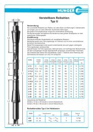
L2<br />
L3<br />
- 48 - Expanding Reamers<br />
a<br />
L1<br />
Type K<br />
Description:<br />
Rigth-hand cutting reamer with expanding blades.<br />
Parallel shank with square at the back and integral pilot with sliding cone<br />
bush at the front of the reamer.<br />
Due to the unique <strong>Hunger</strong> relief grinding operation the blades have a progressively<br />
increasing clearance angle giving a softer cutting action.<br />
Starting with size K 12 the adjusting nut is marked with a circular scale.<br />
One graduation of the scale corresponds to an alteration of the reamer diameter<br />
by 0,01 mm.<br />
Application:<br />
The precision reamer for inline reaming of holes.<br />
The cone bush holds the reamer in exact alignment when reaming two holes.<br />
Size Size Length Length Length Size of No. of Weight<br />
Range Overall Blades Pilot Square Blades<br />
mm Inches L1 mm L2 mm L3 mm a mm kg<br />
K 7 7 - 8 9 /32 - 5 / 16 175 32 65 3,5 4 0,<strong>03</strong>0<br />
K 8 8 - 9 5 /16 - 23 / 64 175 32 65 4,3 5 0,055<br />
K 9 9 - 10 23 /64 - 25 / 64 175 32 65 4,3 5 0,065<br />
K 10 10 - 11 25 /64 - 7 / 16 185 35 68 4,9 5 0,085<br />
K 11 11 - 12 7 /16 - 15 / 32 195 35 72 6,2 5 0,100<br />
K 12 12 - 13,5 15 /32 - 17 / 32 215 42 84 6,2 5 0,130<br />
K 13,5 13,5 - 15,5 17 /32 - 39 / 64 235 50 89 7 5 0,180<br />
K 15,5 15,5 - 18 39 /64 - 45 / 64 265 60 98 8 5 0,280<br />
K 18 18 - 21 45 /64 - 53 / 64 290 65 109 9 5 0,410<br />
K 21 21 - 24 53 /64 - 15 / 16 310 70 119 10 5 0,570<br />
K 24 24 - 27,5 15 /16 -1 5 / 64 335 75 129 11 5 0,770<br />
K 27,5 27,5 - 31,5 1 5 / 64 -1 15 / 64 365 80 137 12 6 1,040<br />
K 31,5 31,5 - 37 1 15 / 64 -1 29 / 64 400 90 159 14,5 6 1,550<br />
K 37 37 - 45 1 29 / 64 -1 49 / 64 465 100 180 16 6 2,550<br />
K 45 45 - 55 1 49 / 64 -2 5 / 32 530 109 198 20 6 5,000<br />
K 55 55 - 65 2 5 / 32 -2 9 / 16 570 120 213 24 8 6,450<br />
K 65 65 - 80 2 9 /16 -3 5 /32 670 145 250 29 10 11,900<br />
K 80 80 - 95 3 5 /32 -3 47 /64 700 150 250 32 10 13,700<br />
K 95 95 - 110 347 / 64 -4 21 / 64 700 150 250 36 10 23,900<br />
Packing of the reamers:<br />
From size K 7 to K 37 individually in clear plastic tube containers.<br />
From size K 45 to K 55 individually in plastic nets.<br />
From size K 65 to K 95 individually in wooden boxes.<br />
Sets of Reamers Type K in Wooden Cases<br />
Symbol Size Range No. of Weight<br />
mm Inches Reamers kg<br />
KAN 8 - 31,5 21 /64 - 1 15 / 64 11 5,200<br />
KEN 8 - 45 21 /64 - 1 49 /64 13 10,700
L4<br />
L2<br />
L3<br />
a<br />
a<br />
L1<br />
Expanding Reamers - 49 -<br />
Type U<br />
Description:<br />
Rigth-hand cutting reamer with expanding blades.<br />
Exchangeable pilots at the front as well as at the back of the reamer.<br />
Each pilot is provided with square and sliding cone bush.<br />
A special bayonet coupling with mating cones between each pilot and the<br />
reamer body ensures correct alignment. For extension pilots see page 9.<br />
The blades are ground for taking a rough cut followed by finish reaming.<br />
Due to the unique <strong>Hunger</strong> relief grinding operation the blades have a progressively<br />
increasing clearance angle giving a softer cutting action.<br />
The adjusting nut is marked with a circular scale.<br />
One graduation of the scale corresponds to an alteration of the reamer diameter<br />
by 0,02 mm.<br />
Application:<br />
The universal reamer for all types of holes, particularly for inline reaming of<br />
two or more holes.<br />
The cone bushes provide for exact alignment between the hole being reamed<br />
and the other mating holes.<br />
Size Size Length Length Length Length Size of No. of Weight<br />
Range Overall Blades Pilot Pilot Square Blades<br />
mm L1 mm L2 mm L 3 mm L 4 mm a mm kg<br />
U 12 12 - 13,5 250 30 110 82 8 5 0,170<br />
U 13,5 13,5 - 15,5 270 33 116 84 9 5 0,245<br />
U 15,5 15,5 - 18 295 36 127 88 10 5 0,360<br />
U 18 18 - 21 330 40 140 100 12 5 0,545<br />
U 19,5 19,5 - 22,5 352 44 150 110 13 5 0,700<br />
U 21 21 - 24,5 352 44 150 110 13 5 0,800<br />
U 24,5 24,5 - 29 385 48 157 118 13 6 1,140<br />
U 29 29 - 34 418 52 170 130 16 6 1,670<br />
U 34 34 - 39 440 54 180 140 18 6 2,430<br />
U 39 39 - 45 475 60 190 150 18 6 3,310<br />
U 45 45 - 52 500 60 200 162 18 6 4,700<br />
U 52 52 - 59 500 60 200 162 18 6 5,700<br />
U 59 59 - 66 500 60 200 162 18 6 6,700<br />
Packing of the reamers:<br />
From Size U 12 to U 39 individually in clear plastic tube containers.<br />
From Size U 45 to U 59 individually in plastic nets.<br />
Sets of Reamers Type U in Wooden Cases<br />
Symbol Size Range No. of Weight<br />
mm Inches Reamers kg<br />
USI 12 - 34 15 /32 - 1 11 / 32 7 6,700<br />
USE 12 - 45 15 /32 - 1 49 /64 9 13,100
L4<br />
L3<br />
- 50 - Expanding Reamers<br />
Type U Pilots<br />
Design:<br />
Each pilot has a square at the one end and a female cone at the other end.<br />
The female cone in the pilot is designed to receive the mating male cone at<br />
the reamer body.<br />
Pilot and reamer body are interlocked by a bayonet type coupling.<br />
As the mating cones usually stick firmly together, the use of a plastic hammer<br />
is recommended to loosen the firm contact before removing the pilot<br />
from the reamer body. Apply ligth taps onto the pilot around the female cone.<br />
With the contact thus loosened, turn the pilot clockwise with respect to the<br />
reamer body until the triangular projection provided at the male cone is in<br />
the middle of the recess provided in the female cone. Then withdraw pilot<br />
from reamer body.<br />
Size of Standard Front Pilots Standard Back Pilots Extension Pilots Size I<br />
Reamer Length Length Length<br />
L3 mm Part No. L4 mm Part No. mm Part No.<br />
U 12 110 130 12 701 82 130 12 702 210 132 12 711<br />
U 13,5 116 130 13 701 84 130 13 702 220 132 13 712<br />
U 15,5 127 130 15 701 88 130 15 702 230 132 15 713<br />
U 18 140 130 18 701 100 130 18 702 240 132 18 714<br />
U 19,5 150 130 19 701 110 130 19 702 250 132 19 715<br />
U 21 150 130 21 701 110 130 21 702 250 132 21 715<br />
U 24,5 157 130 24 701 118 130 24 702 260 132 24 716<br />
U 29 170 130 29 701 130 130 29 702 270 132 29 717<br />
U 34 180 130 34 701 140 130 34 702 280 132 34 718<br />
U 39 190 130 39 701 150 130 39 702 290 132 39 719<br />
U 45 200 130 45 701 162 130 45702 400 132 45 730<br />
U 52 200 130 52 701 162 130 52 702 400 132 52 730<br />
U 59 200 130 52 701 162 130 59 702 400 132 52 730<br />
Size of Extension Pilots Size II Extension Pilots Size III Extension Pilots Size IV<br />
Reamer Length Length Length<br />
mm Part No. mm Part No. mm Part No.<br />
U 12 410 132 12 731 610 132 12 751 810 132 12 771<br />
U 13,5 420 132 13 732 620 132 13 752 820 132 13 772<br />
U 15,5 430 132 15 733 630 132 15 753 830 132 15 773<br />
U 18 440 132 18 734 640 132 18 754 840 132 18 774<br />
U 19,5 450 132 19 735 650 132 19 755 - -<br />
U 21 450 132 21 735 650 132 21 755 850 132 21 775<br />
U 24,5 460 132 24 736 660 132 24 756 860 132 24 776<br />
U 29 470 132 29 737 670 132 29 757 870 132 29 777<br />
U 34 480 132 34 738 680 132 34 758 880 132 34 778<br />
U 39 490 132 39 739 690 132 39 759 890 132 39 779<br />
U 45 600 132 45 750 800 132 45 770 900 132 45 780<br />
U 52 600 132 52 750 800 132 52 770 900 132 52 780<br />
U 59 600 132 52 750 800 132 59 770 900 132 52 780<br />
Special length extension pilots available on request.
L2<br />
d<br />
SW<br />
L1<br />
Expanding Reamers - 51 -<br />
Type H<br />
Design:<br />
Right-hand cutting shell reamer with expanding blades.<br />
The reamer fits on a tool bar and may be positioned along the tool bar at<br />
any desired position.<br />
The reamer is automatically locked in place on the tool bar by an ex-panding<br />
spring coupling as soon as the reamer blades are brought into<br />
engagement with the bore.<br />
Expanding tool bar guides and supporting fixtures for the tool bar are<br />
available to ensure excact alignment of the tool bar when reaming a<br />
series of aligned holes.<br />
The adjusting nut is marked with a circular scale. One graduation of the<br />
scale corresponds to an alteration of the reamer diameter by 0,02 mm.<br />
Application:<br />
The reamer for inline reaming of a series of holes, particularly the holes<br />
of crankshaft and camshaft bearings.<br />
Size Size Takes Length Length Nut No. of Weight<br />
Range Tool Bar Overall Blades SW Blades<br />
mm d mm L1 mm L2 mm mm kg<br />
H 36 36 - 38 20 96 44 32 6 0,370<br />
H 38 38 - 41 20 99 44 34 6 0,450<br />
H 41 41 - 44 20 104 48 38 6 0,590<br />
H 44 44 - 47 25 104 48 40 6 0,590<br />
H 47 47 - 51 25 108 48 43 6 0,760<br />
H 51 51 - 54 30 108 52 47 5 0,830<br />
H 54 54 - 58 30 113 52 47 6 0,930<br />
H 58 58 - 62 30 113 52 53 6 1,180<br />
H 62 62 - 65 35 114 52 58 8 1,290<br />
H 65 65 - 69 35 118 57 58 8 1,490<br />
H 69 69 - 73 40 118 57 64 8 1,790<br />
H 73 73 - 78 40 123 57 68 8 1,990<br />
H 78 78 - 83 45 124 57 70 8 2,110<br />
H 83 83 - 88 45 124 60 78 8 2,750<br />
H 88 88 - 93 50 124 60 83 8 3,000<br />
H 93 93 - 99 50 127 60 83 10 3,490<br />
H 99 99 - 105 50 127 60 * 10 4,200<br />
H 105 105 - 111 50 127 60 * 10 5,040<br />
Reamers type H with size range over<br />
111 mm on application.<br />
* Adjustment of the nut<br />
with hook wrench.
L<br />
- 52 - Expanding Reamers<br />
D<br />
SW<br />
d<br />
Type H Tool Bars and Guides<br />
Tool Bars for Reamers Type H<br />
Description:<br />
Precision ground bars with squares at both ends.<br />
Standard types are listed below.<br />
Special length guide bars on application.<br />
Order Information:<br />
Tool Bar<br />
for Diameter Length Square Weight<br />
Part No. Reamer Size D mm L mm SW mm kg<br />
152 20 101 H 36 - H 41 20 1000 13 2,420<br />
152 25 101 H 44 - H 47 25 1000 13 3,740<br />
152 30 121 H 51 - H 58 30 1200 16 6,540<br />
152 30 151 H 51 - H 58 30 1500 16 12,000<br />
152 35 121 H 62 - H 65 35 1200 18 8,750<br />
152 40 151 H 69 - H 73 40 1500 18 14,400<br />
152 45 151 H 78 - H 83 45 1500 22 18,110<br />
152 50 171 H 88 - H 105 50 1700 22 25,200<br />
Expanding Tool Bar Guides<br />
Description:<br />
The tool bar guides are provided with wedges which can be forced<br />
outward against the hole to lock the tool bar guide in the hole.<br />
The wedges are actuated by an adjusting nut.<br />
Order Information:<br />
Tool Bar Guides<br />
for Bore Expansion Range Weight<br />
Part No. Reamer Size d mm mm kg<br />
153 20 000 H 36 - H 41 20 35,5 - 54 0,200<br />
153 25 000 H 44 - H 47 25 43,5 - 62 0,300<br />
153 30 000 H 51 - H 58 30 49,5 - 74 0,410<br />
153 35 000 H 62 - H 65 35 61,5 - 83 0,620<br />
153 40 000 H 69 - H 73 40 68,5 - 93 0,800<br />
153 45 000 H 78 - H 83 45 77,5 - 105 1,100<br />
153 50 000 H 88 - H 105 50 87,5 - 127 1,550
3<br />
6 7<br />
Align Reaming and Boring - 53 -<br />
Example<br />
1<br />
Machining of bearing tunnels<br />
from 36 to 110mm diameter<br />
The individual parts:<br />
1<br />
2<br />
3<br />
4<br />
5<br />
6<br />
7<br />
4<br />
Expanding reamer type H<br />
Tool bar<br />
Expanding tool bar guide<br />
Supporting fixture<br />
Guide bush<br />
Boring head<br />
Feed unit<br />
5<br />
2
- 54 - Align Reaming and Boring<br />
Supporting Fixture for Tool Bars<br />
Supporting Fixture<br />
Description:<br />
The universal supporting fixture is designed to locate a tool bar guide bush in front of an end<br />
bearing hole for perfect alignment of the tool bar in centerline with the hole.<br />
The guide bush is locked in a clamping arm which is connected by a ball joint to a mounting<br />
base which is attached to the cylinder block or cylinder head.<br />
Both the clamping arm and the ball joint are adjustable to ensure proper alignment.<br />
Mounting Base<br />
Order Information:<br />
L1<br />
Ball Joint<br />
Clamping Arm<br />
Tool Bar<br />
Supportin Fixture Individual Components of the Supporting Fixture<br />
Size Part No. Weight Mounting Base Clamping Arm Ball Joint<br />
kg Size Part No. L1 mm Size Part No. L2 mm Part No.<br />
IA 156 11 100 3,140 IA 156 11 110 330 IA 156 11 120 210 156 11 130<br />
IIA 156 12 100 5,100 IIA 156 12 110 400 IIA 156 12 120 270 156 11 130<br />
IIA1 156 12 102 5,100 IIA 156 12 110 400 IA 156 11 120 210 156 11 130<br />
Guide Bushes for Clamping Arm Size IA<br />
Size Part No. Bore Dia. Weight<br />
for Bar kg<br />
IA/20 156 21 200 20 mm 0,920<br />
IA/25 156 21 250 25 mm 0,880<br />
IA/30 156 21 300 30 mm 0,820<br />
IA/35 156 21 350 35 mm 0,750<br />
IA/40 156 21 400 40 mm 0,650<br />
IA/45 156 21 450 45 mm 0,600<br />
IA/50 156 21 500 50 mm 0,550<br />
Guide Bush<br />
L2<br />
Guide Bushes for Clamping Arm Size IIA<br />
Size Part No. Bore Dia. Weight<br />
for Bar kg<br />
IIA/40 156 22 400 40 mm 1,940<br />
IIA/45 156 22 450 45 mm 1,890<br />
IIA/50 156 22 500 50 mm 1,800
D<br />
d<br />
Align Reaming and Boring - 55 -<br />
Boring Heads & Feed Devices<br />
Boring Heads<br />
Description:<br />
Then.boring heads are designed to counterbore the hole<br />
befor finish reaming<br />
The boring heads are fitted with an adjustable single point<br />
cutting tool..<br />
A set screw is provided to adjust the cutting tool.<br />
Boring Dimensions Weight<br />
head Diameter of hole Range of ad- kg<br />
Part for tool bar justing tool bar<br />
No. d mm D mm<br />
154 30 000 30 50 - 58 0,340<br />
154 31 000 30 53 - 62 0,420<br />
154 35 000 35 61 - 69 0,520<br />
154 40 000 40 68 - 78 0,660<br />
154 45 000 45 77 - 88 0,870<br />
154 50 000 50 87 - 99 1,230<br />
154 52 000 50 92 - 105 1,440<br />
154 54 000 50 98 - 111 1,670<br />
Boring heads and tool bars for 20 & 25 mm on request.<br />
Feed Devices<br />
Description:<br />
The feed devices provide automated feed of the tool bar in<br />
axial direction when the tool bar is rotated.<br />
The feed device must be located just behind the guide<br />
bush.<br />
A knurled screw is provided for engaging and disengaging<br />
the automated feed.<br />
Feed<br />
device Diameter of hole Weight<br />
Part for tool bar kg<br />
No. mm<br />
155 20 000 20 0,330<br />
155 25 000 25 0,360<br />
155 30 000 30 0,730<br />
155 35 000 35 0,760<br />
155 40 000 40 0,830<br />
155 45 000 45 0,840<br />
155 50 000 50 0,850