KR 5 scara R350, R550 - KUKA Roboter
KR 5 scara R350, R550 - KUKA Roboter
KR 5 scara R350, R550 - KUKA Roboter

Create successful ePaper yourself
Turn your PDF publications into a flip-book with our unique Google optimized e-Paper software.
Robots<br />
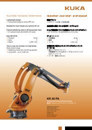
<strong>KR</strong> 5 <strong>scara</strong> <strong>R350</strong>, <strong>R550</strong><br />
Specification<br />
Issued: 23.08.2011<br />
Version: Spez <strong>KR</strong> 5 <strong>scara</strong> V6 en<br />
<strong>KUKA</strong> <strong>Roboter</strong> GmbH
<strong>KR</strong> 5 <strong>scara</strong> <strong>R350</strong>, <strong>R550</strong><br />
© Copyright 2011<br />
<strong>KUKA</strong> <strong>Roboter</strong> GmbH<br />
Zugspitzstraße 140<br />
D-86165 Augsburg<br />
Germany<br />
This documentation or excerpts therefrom may not be reproduced or disclosed to third parties without<br />
the express permission of <strong>KUKA</strong> <strong>Roboter</strong> GmbH.<br />
Other functions not described in this documentation may be operable in the controller. The user has<br />
no claims to these functions, however, in the case of a replacement or service work.<br />
We have checked the content of this documentation for conformity with the hardware and software<br />
described. Nevertheless, discrepancies cannot be precluded, for which reason we are not able to<br />
guarantee total conformity. The information in this documentation is checked on a regular basis, however,<br />
and necessary corrections will be incorporated in the subsequent edition.<br />
Subject to technical alterations without an effect on the function.<br />
Translation of the original documentation<br />
KIM-PS5-DOC<br />
Publication: Pub Spez <strong>KR</strong> 5 <strong>scara</strong> en<br />
Bookstructure: Spez <strong>KR</strong> 5 <strong>scara</strong> V7.1<br />
Version: Spez <strong>KR</strong> 5 <strong>scara</strong> V6 en<br />
2 / 57 Issued: 23.08.2011 Version: Spez <strong>KR</strong> 5 <strong>scara</strong> V6 en
Contents<br />
Issued: 23.08.2011 Version: Spez <strong>KR</strong> 5 <strong>scara</strong> V6 en<br />
Contents<br />
1 Product description ..................................................................................... 5<br />
1.1 Overview of the robot system .................................................................................... 5<br />
1.2 Description of the <strong>KR</strong> 5 <strong>scara</strong> robot ........................................................................... 5<br />
2 Technical data .............................................................................................. 7<br />
2.1 Basic data .................................................................................................................. 7<br />
2.2 Axis data .................................................................................................................... 8<br />
2.3 Payloads .................................................................................................................... 13<br />
2.3.1 Mounting flange (optional) .................................................................................... 15<br />
2.4 Loads acting on the foundation .................................................................................. 15<br />
2.5 Additional data ........................................................................................................... 16<br />
2.6 Plates and labels ........................................................................................................ 17<br />
3 Safety ............................................................................................................ 19<br />
3.1 General ...................................................................................................................... 19<br />
3.1.1 Liability .................................................................................................................. 19<br />
3.1.2 Intended use of the industrial robot ...................................................................... 19<br />
3.1.3 EC declaration of conformity and declaration of incorporation ............................. 20<br />
3.1.4 Terms used ........................................................................................................... 21<br />
3.2 Personnel ................................................................................................................... 21<br />
3.3 Workspace, safety zone and danger zone ................................................................. 23<br />
3.4 Triggers for stop reactions ......................................................................................... 23<br />
3.5 Safety functions ......................................................................................................... 24<br />
3.5.1 Overview of safety functions ................................................................................. 24<br />
3.5.2 ESC safety logic ................................................................................................... 24<br />
3.5.3 Mode selector switch ............................................................................................ 25<br />
3.5.4 Operator safety ..................................................................................................... 26<br />
3.5.5 EMERGENCY STOP device ................................................................................ 26<br />
3.5.6 External EMERGENCY STOP device .................................................................. 27<br />
3.5.7 Enabling device .................................................................................................... 27<br />
3.6 Additional protective equipment ................................................................................. 28<br />
3.6.1 Jog mode .............................................................................................................. 28<br />
3.6.2 Software limit switches ......................................................................................... 28<br />
3.6.3 Labeling on the industrial robot ............................................................................. 29<br />
3.6.4 External safeguards .............................................................................................. 29<br />
3.7 Overview of operating modes and safety functions ................................................... 30<br />
3.8 Safety measures ........................................................................................................ 30<br />
3.8.1 General safety measures ...................................................................................... 30<br />
3.8.2 Transportation ....................................................................................................... 31<br />
3.8.3 Start-up and recommissioning .............................................................................. 32<br />
3.8.4 Virus protection and network security ................................................................... 33<br />
3.8.5 Manual mode ........................................................................................................ 33<br />
3.8.6 Simulation ............................................................................................................. 34<br />
3.8.7 Automatic mode .................................................................................................... 34<br />
3.8.8 Maintenance and repair ........................................................................................ 35<br />
3.8.9 Decommissioning, storage and disposal .............................................................. 36<br />
3.8.10 Safety measures for “single point of control” ........................................................ 36<br />
3 / 57
<strong>KR</strong> 5 <strong>scara</strong> <strong>R350</strong>, <strong>R550</strong><br />
3.9 Applied norms and regulations .................................................................................. 37<br />
4 Planning ........................................................................................................ 39<br />
4.1 Mounting base ........................................................................................................... 39<br />
4.2 Instructions for mechanical axis range limitation ....................................................... 39<br />
4.2.1 Instructions for mechanical axis range limitation on axis 1 ................................... 40<br />
4.2.2 Instructions for mechanical axis range limitation on axis 2 ................................... 41<br />
4.2.3 Instructions for mechanical axis range limitation on axis 3 ................................... 41<br />
5 Transportation ............................................................................................. 43<br />
5.1 Transporting the robot ............................................................................................... 43<br />
6 <strong>KUKA</strong> Service ............................................................................................... 47<br />
6.1 Requesting support ................................................................................................... 47<br />
6.2 <strong>KUKA</strong> Customer Support ........................................................................................... 47<br />
Index ............................................................................................................. 55<br />
4 / 57 Issued: 23.08.2011 Version: Spez <strong>KR</strong> 5 <strong>scara</strong> V6 en
1 Product description<br />
1.1 Overview of the robot system<br />
Issued: 23.08.2011 Version: Spez <strong>KR</strong> 5 <strong>scara</strong> V6 en<br />
The robot system consists of the following components:<br />
Manipulator<br />
Robot controller<br />
KCP teach pendant<br />
Connecting cables<br />
Software<br />
Options, accessories<br />
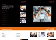
Fig. 1-1: Example of a robot system<br />
1.2 Description of the <strong>KR</strong> 5 <strong>scara</strong> robot<br />
1 Product description<br />
1 Robot 3 Teach pendant (KCP)<br />
2 Robot controller 4 Connecting cable<br />
Overview The robot is a 4-axis jointed-arm robot made of cast light alloy. All motor units<br />
and current-carrying cables are protected against dirt and moisture beneath<br />
screwed-on cover plates.<br />
The robot consists of the following principal components:<br />
Arm<br />
Link arm<br />
Base frame<br />
Electrical installations<br />
Spindle<br />
5 / 57
<strong>KR</strong> 5 <strong>scara</strong> <strong>R350</strong>, <strong>R550</strong><br />
Fig. 1-2: Principal components<br />
1 Arm 4 Base frame<br />
2 Spindle 5 Electrical installations<br />
3 Link arm<br />
Arm The arm incorporates axes 2, 3 and 4. Axes 2 and 4 are rotational axes,<br />
whereas axis 3 is a translational axis. All motors for these axes are contained<br />
in the arm. Axis 2 is driven directly via a gear unit, while axes 3 and 4 are driven<br />
via an upstream toothed belt stage. The motors of these two axes are each<br />
equipped with a brake.<br />
The mounting flange can be attached to the interface of axis 4.<br />
Depending on the travel of the translational axis 3, the robot type is specified<br />
as Z200 or Z320. Z200 stands for a travel of 200 mm, and Z320 for a travel of<br />
320 mm.<br />
The arm also accommodates the 10-contact circular connector of the wrist I/O<br />
cable.<br />
Link arm The link arm is a hollow structural element which is mounted on the base<br />
frame and screwed to the drive elements of the arm. The supply lines and signal<br />
cables for the drives of axes 2 and 4, and the lines of the energy supply<br />
system (wrist I/O cable and compressed air lines) are routed through the link<br />
arm.<br />
Base frame The base frame is the base of the robot. It houses the motor for axis 1. It constitutes<br />
the interface for the connecting cables between the robot, the robot<br />
controller and the energy supply system. All connecting cables are accommodated<br />
at the rear of the base frame. The base frame houses the backup batteries<br />
for backing up the axis data of the position sensing system.<br />
6 / 57 Issued: 23.08.2011 Version: Spez <strong>KR</strong> 5 <strong>scara</strong> V6 en
2 Technical data<br />
2.1 Basic data<br />
Basic data<br />
Pneumatic<br />
interface<br />
Vibration stress<br />
Ambient temperature<br />
Issued: 23.08.2011 Version: Spez <strong>KR</strong> 5 <strong>scara</strong> V6 en<br />
Type <strong>KR</strong> 5 <strong>scara</strong> <strong>R350</strong><br />
<strong>KR</strong> 5 <strong>scara</strong> <strong>R550</strong><br />
Number of axes 4<br />
Volume of working<br />
envelope<br />
<strong>KR</strong> 5 <strong>scara</strong> <strong>R350</strong>-Z200: 0.064 m 3<br />
<strong>KR</strong> 5 <strong>scara</strong> <strong>R350</strong>-Z320: 0.102 m 3<br />
Repeatability<br />
(ISO 9283)<br />
Working envelope reference<br />
point<br />
Weight approx. 20 kg<br />
Principal dynamic<br />
loads<br />
Protection classification<br />
of the robot<br />
<strong>KR</strong> 5 <strong>scara</strong> <strong>R550</strong>-Z200: 0.165 m 3<br />
<strong>KR</strong> 5 <strong>scara</strong> <strong>R550</strong>-Z320: 0.264 m 3<br />
<strong>KR</strong> 5 <strong>scara</strong> <strong>R350</strong>: ±0.015 mm<br />
<strong>KR</strong> 5 <strong>scara</strong> <strong>R550</strong>: ±0.020 mm<br />
Intersection of axes 3 and 4<br />
See “Loads acting on the mounting base”<br />
2 Technical data<br />
IP 40, ready for operation, with connecting<br />
cables plugged in (according to EN 60529)<br />
Sound level < 75 dB (A) outside the working envelope<br />
Mounting position Floor<br />
Surface finish, paint- Plastic: white, paintwork: white, base frame:<br />
work<br />
black<br />
Operating pressure,<br />
infeed<br />
0.05 to 0.35 MPa<br />
Max. pressure 0.59 MPa<br />
Operation No permanent vibration stress permissible<br />
Brief, one-off: 0.5 g<br />
Storage and transpor- Brief, one-off: 3 g<br />
tation<br />
Operation 0 °C to +40 °C (273 K to 313 K)<br />
Relative air humidity ≤ 90%<br />
No condensation permissible.<br />
Storage and transpor- -10 °C to +60 °C (263 K to 333 K)<br />
tation<br />
Relative air humidity ≤ 75%<br />
No condensation permissible.<br />
7 / 57
<strong>KR</strong> 5 <strong>scara</strong> <strong>R350</strong>, <strong>R550</strong><br />
Ambient conditions<br />
Connecting<br />
cables<br />
2.2 Axis data<br />
Axis data<br />
Operation Free from inflammable dust, gases and liquids<br />
Free from aggressive and corrosive gases<br />
and liquids<br />
Free from flying parts<br />
Free from spraying liquids<br />
Free from electromagnetic loads, e.g. from<br />
welding equipment or high-frequency converters<br />
Cable lengths: 4 m, 6 m, 12 m<br />
The connecting cables consist of the motor/data cable and the wrist I/O cable.<br />
The following connector designations and connections are used:<br />
Cable designation Connector<br />
designation<br />
Robot controller - Robot<br />
Motor/data cable X20 - CN22 Harting circular connector<br />
Wrist I/O cable X32 - CN20 D-Sub circular connector<br />
Ground conductor PE M5 cable lug at each end<br />
For detailed specifications of the connecting cables, see<br />
The data are valid for the floor-mounted <strong>KR</strong> 5 <strong>scara</strong> <strong>R350</strong> and <strong>KR</strong> 5 <strong>scara</strong><br />
<strong>R550</strong> robots.<br />
Axis Range of motion, softwarelimited<br />
Speed with rated payload 5 kg<br />
1 +/-155° 525°/s with <strong>R350</strong><br />
450°/s with <strong>R550</strong><br />
2 +/-145° 525°/s with <strong>R350</strong><br />
720°/s with <strong>R550</strong><br />
3 with Z200:<br />
+246 mm / +46 mm<br />
with Z320:<br />
+246 mm / -74 mm<br />
2,000 mm/s<br />
4 +/-358° 2,400°/s<br />
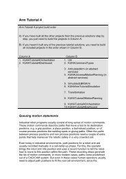
The direction of motion and the arrangement of the individual axes may be noted<br />
from the following diagram.<br />
8 / 57 Issued: 23.08.2011 Version: Spez <strong>KR</strong> 5 <strong>scara</strong> V6 en
Working<br />
envelope<br />
Fig. 2-1: Robot axes<br />
Issued: 23.08.2011 Version: Spez <strong>KR</strong> 5 <strong>scara</strong> V6 en<br />
2 Technical data<br />
The following diagrams show the shape and size of the working envelopes.<br />
9 / 57
<strong>KR</strong> 5 <strong>scara</strong> <strong>R350</strong>, <strong>R550</strong><br />
Fig. 2-2: Working envelope <strong>KR</strong> 5 <strong>scara</strong> <strong>R350</strong> Z200<br />
10 / 57 Issued: 23.08.2011 Version: Spez <strong>KR</strong> 5 <strong>scara</strong> V6 en
Fig. 2-3: Working envelope <strong>KR</strong> 5 <strong>scara</strong> <strong>R350</strong> Z320<br />
Issued: 23.08.2011 Version: Spez <strong>KR</strong> 5 <strong>scara</strong> V6 en<br />
2 Technical data<br />
11 / 57
<strong>KR</strong> 5 <strong>scara</strong> <strong>R350</strong>, <strong>R550</strong><br />
Fig. 2-4: Working envelope <strong>KR</strong> 5 <strong>scara</strong> <strong>R550</strong> Z200<br />
12 / 57 Issued: 23.08.2011 Version: Spez <strong>KR</strong> 5 <strong>scara</strong> V6 en
2.3 Payloads<br />
Payloads<br />
Issued: 23.08.2011 Version: Spez <strong>KR</strong> 5 <strong>scara</strong> V6 en<br />
Fig. 2-5: Working envelope <strong>KR</strong> 5 <strong>scara</strong> <strong>R550</strong> Z320<br />
2 Technical data<br />
Robot <strong>KR</strong> 5 <strong>scara</strong><br />
Rated payload 5 kg<br />
Distance of the load center of gravity Lx 100 mm<br />
Distance of the load center of gravity Ly 0 mm<br />
Distance of the load center of gravity Lz 80 mm<br />
Max. total load 5 kg<br />
13 / 57
<strong>KR</strong> 5 <strong>scara</strong> <strong>R350</strong>, <strong>R550</strong><br />
Load center of<br />
gravity P<br />
For all payloads, the load center of gravity refers to the distance from the face<br />
of the mounting flange on axis 4.<br />
Payload diagram Permissible mass inertia at the design point (L x , L y , L z ) is 0.1 kgm².<br />
Supplementary<br />
load<br />
Fig. 2-6: Payload on the robot<br />
1 FLANGE coordinate system<br />
2 Load center of gravity<br />
3 Robot<br />
4 Distances LX , LY , LZ of the load center of gravity<br />
Fig. 2-7: Payload diagram<br />
This loading curve corresponds to the maximum load capacity.<br />
Both values (payload and mass moment of inertia)<br />
must be checked in all cases. Exceeding this capacity will reduce the<br />
service life of the robot and overload the motors and the gears; in any such<br />
case the <strong>KUKA</strong> <strong>Roboter</strong> GmbH must be consulted beforehand.<br />
The values determined here are necessary for planning the robot application.<br />
For commissioning the robot, additional input data are required in accordance<br />
with operating and programming instructions of the <strong>KUKA</strong> System<br />
Software.<br />
The mass inertia must be verified using <strong>KUKA</strong>.Load. It is imperative for the<br />
load data to be entered in the robot controller!<br />
The robot cannot carry supplementary loads.<br />
14 / 57 Issued: 23.08.2011 Version: Spez <strong>KR</strong> 5 <strong>scara</strong> V6 en
2.3.1 Mounting flange (optional)<br />
Issued: 23.08.2011 Version: Spez <strong>KR</strong> 5 <strong>scara</strong> V6 en<br />
2 Technical data<br />
The mounting flange can be made by the user. For this, the following dimensions<br />
must be taken into consideration.<br />
2.4 Loads acting on the foundation<br />
Loads acting on<br />
the foundation<br />
The mounting flange is not included in the scope of supply of the robot.<br />
Mounting flange DIN/ISO 9409-1-A31,5<br />
Strength class 10.9<br />
Screw size M5.5<br />
Grip length 1.5 x nominal diameter<br />
Depth of engagement 6 mm<br />
Locating element 5 H7<br />
Fig. 2-8: Mounting flange (optional)<br />
Fig. 2-9: Connection A4<br />
The specified forces and moments already include the payload and the inertia<br />
force (weight) of the robot.<br />
15 / 57
<strong>KR</strong> 5 <strong>scara</strong> <strong>R350</strong>, <strong>R550</strong><br />
2.5 Additional data<br />
Accessories Only accessories authorized and offered by <strong>KUKA</strong> may be used for this robot.<br />
All items of equipment must possess the appropriate certification and declarations<br />
of conformity.<br />
Fastening<br />
threads<br />
Fig. 2-10: Loads acting on the mounting base<br />
Type of load Force/torque/mass<br />
Fv = vertical force Fvmax = 200 N<br />
Fh = horizontal force Fhmax = 3,600 N with <strong>R350</strong><br />
Fhmax = 3,900 N with <strong>R550</strong><br />
Mr = torque Mrmax = 1,300 Nm<br />
Total mass for load acting on the 25 kg<br />
mounting base<br />
Robot 20 kg<br />
Total load (suppl. load on arm + 5 kg<br />
rated payload)<br />
The fastening holes serve for fastening the covers, axis range limitations or cable<br />
harnesses.<br />
Fig. 2-11: Fastening threads<br />
16 / 57 Issued: 23.08.2011 Version: Spez <strong>KR</strong> 5 <strong>scara</strong> V6 en
2.6 Plates and labels<br />
1 4 holes, M3, 6 mm deep<br />
2 Arm<br />
3 Link arm<br />
Issued: 23.08.2011 Version: Spez <strong>KR</strong> 5 <strong>scara</strong> V6 en<br />
2 Technical data<br />
Plates and labels The following plates, labels and signs are attached to the robot. They must not<br />
be removed or rendered illegible. Illegible plates, labels and signs must be replaced.<br />
Fig. 2-12: Plates and labels<br />
17 / 57
<strong>KR</strong> 5 <strong>scara</strong> <strong>R350</strong>, <strong>R550</strong><br />
18 / 57 Issued: 23.08.2011 Version: Spez <strong>KR</strong> 5 <strong>scara</strong> V6 en
3 Safety<br />
3.1 General<br />
3.1.1 Liability<br />
Safety information<br />
Issued: 23.08.2011 Version: Spez <strong>KR</strong> 5 <strong>scara</strong> V6 en<br />
3 Safety<br />
The device described in this document is either an industrial robot or a component<br />
thereof.<br />
Components of the industrial robot:<br />
Manipulator<br />
Robot controller<br />
Teach pendant<br />
Connecting cables<br />
External axes (optional)<br />
e.g. linear unit, turn-tilt table, positioner<br />
Software<br />
Options, accessories<br />
The industrial robot is built using state-of-the-art technology and in accordance<br />
with the recognized safety rules. Nevertheless, misuse of the industrial<br />
robot may constitute a risk to life and limb or cause damage to the industrial<br />
robot and to other material property.<br />
The industrial robot may only be used in perfect technical condition in accordance<br />
with its intended use and only by safety-conscious persons who are fully<br />
aware of the risks involved in its operation. Use of the industrial robot is<br />
subject to compliance with this document and with the declaration of incorporation<br />
supplied together with the industrial robot. Any functional disorders affecting<br />
the safety of the industrial robot must be rectified immediately.<br />
Safety information cannot be held against <strong>KUKA</strong> <strong>Roboter</strong> GmbH. Even if all<br />
safety instructions are followed, this is not a guarantee that the industrial robot<br />
will not cause personal injuries or material damage.<br />
No modifications may be carried out to the industrial robot without the authorization<br />
of <strong>KUKA</strong> <strong>Roboter</strong> GmbH. Additional components (tools, software,<br />
etc.), not supplied by <strong>KUKA</strong> <strong>Roboter</strong> GmbH, may be integrated into the industrial<br />
robot. The user is liable for any damage these components may cause to<br />
the industrial robot or to other material property.<br />
In addition to the Safety chapter, this document contains further safety instructions.<br />
These must also be observed.<br />
3.1.2 Intended use of the industrial robot<br />
The industrial robot is intended exclusively for the use designated in the “Purpose”<br />
chapter of the operating instructions or assembly instructions.<br />
Further information is contained in the “Purpose” chapter of the operating<br />
instructions or assembly instructions of the industrial robot.<br />
Using the industrial robot for any other or additional purpose is considered impermissible<br />
misuse. The manufacturer cannot be held liable for any damage<br />
resulting from such use. The risk lies entirely with the user.<br />
Operating the industrial robot and its options within the limits of its intended<br />
use also involves observance of the operating and assembly instructions for<br />
19 / 57
<strong>KR</strong> 5 <strong>scara</strong> <strong>R350</strong>, <strong>R550</strong><br />
the individual components, with particular reference to the maintenance specifications.<br />
Misuse Any use or application deviating from the intended use is deemed to be impermissible<br />
misuse. This includes e.g.:<br />
Transportation of persons and animals<br />
Use as a climbing aid<br />
Operation outside the permissible operating parameters<br />
Use in potentially explosive environments<br />
Operation without additional safeguards<br />
Outdoor operation<br />
3.1.3 EC declaration of conformity and declaration of incorporation<br />
Declaration of<br />
conformity<br />
Declaration of<br />
incorporation<br />
This industrial robot constitutes partly completed machinery as defined by the<br />
EC Machinery Directive. The industrial robot may only be put into operation if<br />
the following preconditions are met:<br />
The industrial robot is integrated into a complete system.<br />
Or: The industrial robot, together with other machinery, constitutes a complete<br />
system.<br />
Or: All safety functions and safeguards required for operation in the complete<br />
machine as defined by the EC Machinery Directive have been added<br />
to the industrial robot.<br />
The complete system complies with the EC Machinery Directive. This has<br />
been confirmed by means of an assessment of conformity.<br />
The system integrator must issue a declaration of conformity for the complete<br />
system in accordance with the Machinery Directive. The declaration of conformity<br />
forms the basis for the CE mark for the system. The industrial robot must<br />
be operated in accordance with the applicable national laws, regulations and<br />
standards.<br />
The robot controller is CE certified under the EMC Directive and the Low Voltage<br />
Directive.<br />
The industrial robot as partly completed machinery is supplied with a declaration<br />
of incorporation in accordance with Annex II B of the EC Machinery Directive<br />
2006/42/EC. The assembly instructions and a list of essential<br />
requirements complied with in accordance with Annex I are integral parts of<br />
this declaration of incorporation.<br />
The declaration of incorporation declares that the start-up of the partly completed<br />
machinery remains impermissible until the partly completed machinery<br />
has been incorporated into machinery, or has been assembled with other parts<br />
to form machinery, and this machinery complies with the terms of the EC Machinery<br />
Directive, and the EC declaration of conformity is present in accordance<br />
with Annex II A.<br />
The declaration of incorporation, together with its annexes, remains with the<br />
system integrator as an integral part of the technical documentation of the<br />
complete machinery.<br />
20 / 57 Issued: 23.08.2011 Version: Spez <strong>KR</strong> 5 <strong>scara</strong> V6 en
3.1.4 Terms used<br />
3.2 Personnel<br />
Issued: 23.08.2011 Version: Spez <strong>KR</strong> 5 <strong>scara</strong> V6 en<br />
3 Safety<br />
Term Description<br />
Axis range Range of each axis, in degrees or millimeters, within which it may move.<br />
The axis range must be defined for each axis.<br />
Stopping distance Stopping distance = reaction distance + braking distance<br />
The stopping distance is part of the danger zone.<br />
Workspace The manipulator is allowed to move within its workspace. The workspace<br />
is derived from the individual axis ranges.<br />
Operator<br />
The user of the industrial robot can be the management, employer or<br />
(User)<br />
delegated person responsible for use of the industrial robot.<br />
Danger zone The danger zone consists of the workspace and the stopping distances.<br />
KCP The KCP (<strong>KUKA</strong> Control Panel) teach pendant has all the operator control<br />
and display functions required for operating and programming the<br />
industrial robot.<br />
Manipulator The robot arm and the associated electrical installations<br />
Safety zone The safety zone is situated outside the danger zone.<br />
Stop category 0 The drives are deactivated immediately and the brakes are applied. The<br />
manipulator and any external axes (optional) perform path-oriented<br />
braking.<br />
Note: This stop category is called STOP 0 in this document.<br />
Stop category 1 The manipulator and any external axes (optional) perform path-maintaining<br />
braking. The drives are deactivated after 1 s and the brakes are<br />
applied.<br />
Note: This stop category is called STOP 1 in this document.<br />
Stop category 2 The drives are not deactivated and the brakes are not applied. The<br />
manipulator and any external axes (optional) are braked with a normal<br />
braking ramp.<br />
Note: This stop category is called STOP 2 in this document.<br />
System integrator System integrators are people who safely integrate the industrial robot<br />
(plant integrator) into a complete system and commission it.<br />
T1 Test mode, Manual Reduced Velocity ( 250 mm/s permissible)<br />
External axis Motion axis which is not part of the manipulator but which is controlled<br />
using the robot controller, e.g. <strong>KUKA</strong> linear unit, turn-tilt table, Posiflex.<br />
The following persons or groups of persons are defined for the industrial robot:<br />
User<br />
Personnel<br />
All persons working with the industrial robot must have read and understood<br />
the industrial robot documentation, including the safety<br />
chapter.<br />
User The user must observe the labor laws and regulations. This includes e.g.:<br />
The user must comply with his monitoring obligations.<br />
The user must carry out instructions at defined intervals.<br />
Personnel Personnel must be instructed, before any work is commenced, in the type of<br />
work involved and what exactly it entails as well as any hazards which may ex-<br />
21 / 57
<strong>KR</strong> 5 <strong>scara</strong> <strong>R350</strong>, <strong>R550</strong><br />
ist. Instruction must be carried out regularly. Instruction is also required after<br />
particular incidents or technical modifications.<br />
Personnel includes:<br />
System integrator<br />
Operators, subdivided into:<br />
Start-up, maintenance and service personnel<br />
Operating personnel<br />
Cleaning personnel<br />
Installation, exchange, adjustment, operation, maintenance and repair<br />
must be performed only as specified in the operating or assembly<br />
instructions for the relevant component of the industrial robot and only<br />
by personnel specially trained for this purpose.<br />
System integrator The industrial robot is safely integrated into a complete system by the system<br />
integrator.<br />
The system integrator is responsible for the following tasks:<br />
Installing the industrial robot<br />
Connecting the industrial robot<br />
Performing risk assessment<br />
Implementing the required safety functions and safeguards<br />
Issuing the declaration of conformity<br />
Attaching the CE mark<br />
Creating the operating instructions for the complete system<br />
Operator The operator must meet the following preconditions:<br />
The operator must be trained for the work to be carried out.<br />
Work on the industrial robot must only be carried out by qualified personnel.<br />
These are people who, due to their specialist training, knowledge and<br />
experience, and their familiarization with the relevant standards, are able<br />
to assess the work to be carried out and detect any potential hazards.<br />
Example The tasks can be distributed as shown in the following table.<br />
Tasks Operator Programmer<br />
Switch robot controller<br />
on/off<br />
System integrator<br />
x x x<br />
Start program x x x<br />
Select program x x x<br />
Select operating mode x x x<br />
Calibration<br />
(tool, base)<br />
x x<br />
Master the manipulator x x<br />
Configuration x x<br />
Programming x x<br />
Start-up x<br />
Maintenance x<br />
Repair x<br />
Decommissioning x<br />
Transportation x<br />
22 / 57 Issued: 23.08.2011 Version: Spez <strong>KR</strong> 5 <strong>scara</strong> V6 en
3.3 Workspace, safety zone and danger zone<br />
3.4 Triggers for stop reactions<br />
Triggers for stop<br />
reactions<br />
Issued: 23.08.2011 Version: Spez <strong>KR</strong> 5 <strong>scara</strong> V6 en<br />
3 Safety<br />
Work on the electrical and mechanical equipment of the industrial robot<br />
may only be carried out by specially trained personnel.<br />
Workspaces are to be restricted to the necessary minimum size. A workspace<br />
must be safeguarded using appropriate safeguards.<br />
The safeguards (e.g. safety gate) must be situated inside the safety zone. In<br />
the case of a stop, the manipulator and external axes (optional) are braked<br />
and come to a stop within the danger zone.<br />
The danger zone consists of the workspace and the stopping distances of the<br />
manipulator and external axes (optional). It must be safeguarded by means of<br />
physical safeguards to prevent danger to persons or the risk of material damage.<br />
Fig. 3-1: Example of axis range A1<br />
1 Workspace 3 Stopping distance<br />
2 Manipulator 4 Safety zone<br />
Stop reactions of the industrial robot are triggered in response to operator actions<br />
or as a reaction to monitoring functions and error messages. The following<br />
table shows the different stop reactions according to the operating mode<br />
that has been set.<br />
STOP 0, STOP 1 and STOP 2 are the stop definitions according to DIN EN<br />
60204-1:2006.<br />
Trigger T1, T2 AUT, AUT<br />
EXT<br />
Safety gate opened - STOP 1<br />
EMERGENCY STOP pressed STOP 0 STOP 1<br />
23 / 57
<strong>KR</strong> 5 <strong>scara</strong> <strong>R350</strong>, <strong>R550</strong><br />
3.5 Safety functions<br />
3.5.1 Overview of safety functions<br />
3.5.2 ESC safety logic<br />
Trigger T1, T2 AUT, AUT<br />
EXT<br />
Enabling withdrawn STOP 0 -<br />
Start key released STOP 2 -<br />
“Drives OFF” key pressed STOP 0<br />
STOP key pressed STOP 2<br />
Operating mode changed STOP 0<br />
Encoder error<br />
(DSE-RDC connection broken)<br />
STOP 0<br />
Motion enable canceled STOP 2<br />
Robot controller switched off<br />
Power failure<br />
STOP 0<br />
Safety functions:<br />
Mode selection<br />
Operator safety (= connection for the guard interlock)<br />
Local EMERGENCY STOP device (= EMERGENCY STOP button on the<br />
KCP)<br />
External EMERGENCY STOP device<br />
Enabling device<br />
These circuits conform to the requirements of category 3 according to EN 954-<br />
1.<br />
In the absence of operational safety functions and safeguards,<br />
the industrial robot can cause personal injury or<br />
material damage. If safety functions or safeguards are dismantled or deactivated,<br />
the industrial robot may not be operated.<br />
The function and triggering of the electronic safety functions are monitored by<br />
the ESC safety logic.<br />
The ESC (Electronic Safety Circuit) safety logic is a dual-channel computeraided<br />
safety system. It permanently monitors all connected safety-relevant<br />
components. In the event of a fault or interruption in the safety circuit, the power<br />
supply to the drives is shut off, thus bringing the industrial robot to a standstill.<br />
The ESC safety logic triggers different stop reactions, depending on the operating<br />
mode of the industrial robot.<br />
The ESC safety logic monitors the following inputs:<br />
Operator safety<br />
Local EMERGENCY STOP (= EMERGENCY STOP button on the KCP)<br />
External EMERGENCY STOP<br />
Enabling device<br />
Operating modes<br />
Qualifying inputs<br />
24 / 57 Issued: 23.08.2011 Version: Spez <strong>KR</strong> 5 <strong>scara</strong> V6 en
3.5.3 Mode selector switch<br />
Issued: 23.08.2011 Version: Spez <strong>KR</strong> 5 <strong>scara</strong> V6 en<br />
3 Safety<br />
The industrial robot can be operated in the following modes:<br />
Manual Reduced Velocity (T1)<br />
Manual High Velocity (T2)<br />
Automatic (AUT)<br />
Automatic External (AUT EXT)<br />
The operating mode is selected using the mode selector switch on the KCP.<br />
The switch is activated by means of a key which can be removed. If the key is<br />
removed, the switch is locked and the operating mode can no longer be<br />
changed.<br />
If the operating mode is changed during operation, the drives are immediately<br />
switched off. The manipulator and any external axes (optional) are stopped<br />
with a STOP 0.<br />
Fig. 3-2: Mode selector switch<br />
1 T2 (Manual High Velocity)<br />
2 AUT (Automatic)<br />
3 AUT EXT (Automatic External)<br />
4 T1 (Manual Reduced Velocity)<br />
Operating<br />
mode<br />
T1<br />
Use Velocities<br />
For test operation, programming<br />
and teaching<br />
T2 For test operation<br />
Program verification:<br />
Programmed velocity, maximum<br />
250 mm/s<br />
Jog mode:<br />
Jog velocity, maximum 250 mm/<br />
s<br />
Program verification:<br />
Programmed velocity<br />
25 / 57
<strong>KR</strong> 5 <strong>scara</strong> <strong>R350</strong>, <strong>R550</strong><br />
3.5.4 Operator safety<br />
Operating<br />
mode<br />
AUT<br />
AUT EXT<br />
3.5.5 EMERGENCY STOP device<br />
Use Velocities<br />
For industrial robots<br />
without higher-level<br />
controllers<br />
Only possible with a<br />
connected safety circuit<br />
For industrial robots<br />
with higher-level controllers,<br />
e.g. PLC<br />
Only possible with a<br />
connected safety circuit<br />
Program mode:<br />
Programmed velocity<br />
Jog mode: Not possible<br />
Program mode:<br />
Programmed velocity<br />
Jog mode: Not possible<br />
The operator safety input is used for interlocking physical safeguards. Safety<br />
equipment, such as safety gates, can be connected to the dual-channel input.<br />
If nothing is connected to this input, operation in Automatic mode is not possible.<br />
Operator safety is not active in the test modes T1 (Manual Reduced Velocity)<br />
and T2 (Manual High Velocity).<br />
In the event of a loss of signal during Automatic operation (e.g. safety gate is<br />
opened), the manipulator and the external axes (optional) stop with a STOP 1.<br />
Once the signal is active at the input again, automatic operation can be resumed.<br />
Operator safety can be connected via the peripheral interface on the robot<br />
controller.<br />
It must be ensured that the operator safety signal is not<br />
automatically reset when the safeguard (e.g. safety gate)<br />
is closed, but only after an additional manual acknowledgement signal has<br />
been given. Only in this way can it be ensured that automatic operation is not<br />
resumed inadvertently while there are still persons in the danger zone, e.g.<br />
due to the safety gate closing accidentally.<br />
Failure to observe this precaution may result in death, severe physical injuries<br />
or considerable damage to property.<br />
The EMERGENCY STOP device for the industrial robot is the EMERGENCY<br />
STOP button on the KCP. The button must be pressed in the event of a hazardous<br />
situation or emergency.<br />
Reactions of the industrial robot if the EMERGENCY STOP button is pressed:<br />
Manual Reduced Velocity (T1) and Manual High Velocity (T2) modes:<br />
The drives are switched off immediately. The manipulator and any external<br />
axes (optional) are stopped with a STOP 0.<br />
Automatic modes (AUT and AUT EXT):<br />
The drives are switched off after 1 second. The manipulator and any external<br />
axes (optional) are stopped with a STOP 1.<br />
Before operation can be resumed, the EMERGENCY STOP button must be<br />
turned to release it and the stop message must be acknowledged.<br />
26 / 57 Issued: 23.08.2011 Version: Spez <strong>KR</strong> 5 <strong>scara</strong> V6 en
3.5.6 External EMERGENCY STOP device<br />
3.5.7 Enabling device<br />
Issued: 23.08.2011 Version: Spez <strong>KR</strong> 5 <strong>scara</strong> V6 en<br />
Fig. 3-3: EMERGENCY STOP button on the KCP<br />
1 EMERGENCY STOP button<br />
3 Safety<br />
Tools and other equipment connected to the manipulator<br />
must be integrated into the EMERGENCY STOP circuit<br />
on the system side if they could constitute a potential hazard.<br />
Failure to observe this precaution may result in death, severe physical injuries<br />
or considerable damage to property.<br />
There must be EMERGENCY STOP devices available at every operator station<br />
that can initiate a robot motion or other potentially hazardous situation.<br />
The system integrator is responsible for ensuring this.<br />
There must always be at least one external EMERGENCY STOP device installed.<br />
This ensures that an EMERGENCY STOP device is available even<br />
when the KCP is disconnected.<br />
External EMERGENCY STOP devices are connected via the customer interface.<br />
External EMERGENCY STOP devices are not included in the scope of<br />
supply of the industrial robot.<br />
The enabling devices of the industrial robot are the enabling switches on the<br />
KCP.<br />
There are 3 enabling switches installed on the KCP. The enabling switches<br />
have 3 positions:<br />
Not pressed<br />
Center position<br />
Panic position<br />
In the test modes, the manipulator can only be moved if one of the enabling<br />
switches is held in the central position. If the enabling switch is released or<br />
pressed fully down (panic position), the drives are deactivated immediately<br />
and the manipulator stops with a STOP 0.<br />
27 / 57
<strong>KR</strong> 5 <strong>scara</strong> <strong>R350</strong>, <strong>R550</strong><br />
3.6 Additional protective equipment<br />
3.6.1 Jog mode<br />
3.6.2 Software limit switches<br />
The enabling switches must not be held down by adhesive<br />
tape or other means or manipulated in any other<br />
way.<br />
Death, serious physical injuries or major damage to property may result.<br />
Fig. 3-4: Enabling switches on the KCP<br />
1 - 3 Enabling switches<br />
In the operating modes T1 (Manual Reduced Velocity) and T2 (Manual High<br />
Velocity), the robot controller can only execute programs in jog mode. This<br />
means that it is necessary to hold down an enabling switch and the Start key<br />
in order to execute a program.<br />
If the enabling switch is released or pressed fully down (panic position), the<br />
drives are deactivated immediately and the manipulator and any external axes<br />
(optional) stop with a STOP 0.<br />
Releasing only the Start key causes the industrial robot to be stopped with a<br />
STOP 2.<br />
The axis ranges of all manipulator and positioner axes are limited by means of<br />
adjustable software limit switches. These software limit switches only serve as<br />
machine protection and must be adjusted in such a way that the manipulator/<br />
positioner cannot hit the mechanical end stops.<br />
The software limit switches are set during commissioning of an industrial robot.<br />
28 / 57 Issued: 23.08.2011 Version: Spez <strong>KR</strong> 5 <strong>scara</strong> V6 en
3.6.3 Labeling on the industrial robot<br />
3.6.4 External safeguards<br />
Issued: 23.08.2011 Version: Spez <strong>KR</strong> 5 <strong>scara</strong> V6 en<br />
3 Safety<br />
All plates, labels, symbols and marks constitute safety-relevant parts of the industrial<br />
robot. They must not be modified or removed.<br />
Labeling on the industrial robot consists of:<br />
Identification plates<br />
Warning labels<br />
Safety symbols<br />
Designation labels<br />
Cable markings<br />
Rating plates<br />
Safeguards The access of persons to the danger zone of the manipulator must be prevented<br />
by means of safeguards.<br />
Physical safeguards must meet the following requirements:<br />
They meet the requirements of EN 953.<br />
They prevent access of persons to the danger zone and cannot be easily<br />
circumvented.<br />
They are sufficiently fastened and can withstand all forces that are likely<br />
to occur in the course of operation, whether from inside or outside the enclosure.<br />
They do not, themselves, represent a hazard or potential hazard.<br />
The prescribed minimum clearance from the danger zone is maintained.<br />
Safety gates (maintenance gates) must meet the following requirements:<br />
They are reduced to an absolute minimum.<br />
The interlocks (e.g. safety gate switches) are linked to the operator safety<br />
input of the robot controller via safety gate switching devices or safety<br />
PLC.<br />
Switching devices, switches and the type of switching conform to the requirements<br />
of category 3 according to EN 954-1.<br />
Depending on the risk situation: the safety gate is additionally safeguarded<br />
by means of a locking mechanism that only allows the gate to be opened<br />
if the manipulator is safely at a standstill.<br />
The button for acknowledging the safety gate is located outside the space<br />
limited by the safeguards.<br />
Other safety<br />
equipment<br />
Further information is contained in the operating and programming instructions.<br />
Further information is contained in the technical data of the operating<br />
instructions or assembly instructions of the components of the industrial<br />
robot.<br />
Further information is contained in the corresponding standards and<br />
regulations. These also include EN 953.<br />
Other safety equipment must be integrated into the system in accordance with<br />
the corresponding standards and regulations.<br />
29 / 57
<strong>KR</strong> 5 <strong>scara</strong> <strong>R350</strong>, <strong>R550</strong><br />
3.7 Overview of operating modes and safety functions<br />
3.8 Safety measures<br />
3.8.1 General safety measures<br />
The following table indicates the operating modes in which the safety functions<br />
are active.<br />
Safety functions T1 T2 AUT AUT EXT<br />
Operator safety - - active active<br />
EMERGENCY STOP device active active active active<br />
Enabling device active active - -<br />
Reduced velocity during program<br />
verification<br />
active - - -<br />
Jog mode active active - -<br />
Software limit switches active active active active<br />
The industrial robot may only be used in perfect technical condition in accordance<br />
with its intended use and only by safety-conscious persons. Operator<br />
errors can result in personal injury and damage to property.<br />
It is important to be prepared for possible movements of the industrial robot<br />
even after the robot controller has been switched off and locked. Incorrect installation<br />
(e.g. overload) or mechanical defects (e.g. brake defect) can cause<br />
the manipulator or external axes to sag. If work is to be carried out on a<br />
switched-off industrial robot, the manipulator and external axes must first be<br />
moved into a position in which they are unable to move on their own, whether<br />
the payload is mounted or not. If this is not possible, the manipulator and external<br />
axes must be secured by appropriate means.<br />
In the absence of operational safety functions and safeguards,<br />
the industrial robot can cause personal injury or<br />
material damage. If safety functions or safeguards are dismantled or deactivated,<br />
the industrial robot may not be operated.<br />
Standing underneath the robot arm can cause death or<br />
serious physical injuries. For this reason, standing underneath<br />
the robot arm is prohibited!<br />
The motors reach temperatures during operation which<br />
can cause burns to the skin. Contact must be avoided.<br />
Appropriate safety precautions must be taken, e.g. protective gloves must be<br />
worn.<br />
KCP The user must ensure that the industrial robot is only operated with the KCP<br />
by authorized persons.<br />
If more than one KCP is used in the overall system, it must be ensured that<br />
each KCP is unambiguously assigned to the corresponding industrial robot.<br />
They must not be interchanged.<br />
30 / 57 Issued: 23.08.2011 Version: Spez <strong>KR</strong> 5 <strong>scara</strong> V6 en
External<br />
keyboard,<br />
external mouse<br />
Issued: 23.08.2011 Version: Spez <strong>KR</strong> 5 <strong>scara</strong> V6 en<br />
3 Safety<br />
An external keyboard and/or external mouse may only be used if the following<br />
conditions are met:<br />
Start-up or maintenance work is being carried out.<br />
The drives are switched off.<br />
There are no persons in the danger zone.<br />
The KCP must not be used as long as an external keyboard and/or external<br />
mouse are connected.<br />
The external keyboard and/or external mouse must be removed as soon as<br />
the start-up or maintenance work is completed or the KCP is connected.<br />
Faults The following tasks must be carried out in the case of faults in the industrial<br />
robot:<br />
Switch off the robot controller and secure it (e.g. with a padlock) to prevent<br />
unauthorized persons from switching it on again.<br />
Indicate the fault by means of a label with a corresponding warning (tagout).<br />
Keep a record of the faults.<br />
Eliminate the fault and carry out a function test.<br />
Modifications After modifications to the industrial robot, checks must be carried out to ensure<br />
the required safety level. The valid national or regional work safety regulations<br />
must be observed for this check. The correct functioning of all safety circuits<br />
must also be tested.<br />
New or modified programs must always be tested first in Manual Reduced Velocity<br />
mode (T1).<br />
After modifications to the industrial robot, existing programs must always be<br />
tested first in Manual Reduced Velocity mode (T1). This applies to all components<br />
of the industrial robot and includes modifications to the software and<br />
configuration settings.<br />
3.8.2 Transportation<br />
Manipulator The prescribed transport position of the manipulator must be observed. Transportation<br />
must be carried out in accordance with the operating instructions or<br />
assembly instructions of the manipulator.<br />
Robot controller The robot controller must be transported and installed in an upright position.<br />
Avoid vibrations and impacts during transportation in order to prevent damage<br />
to the robot controller.<br />
Transportation must be carried out in accordance with the operating instructions<br />
or assembly instructions of the robot controller.<br />
External axis<br />
(optional)<br />
The operator must ensure that decoupled KCPs are immediately<br />
removed from the system and stored out of<br />
sight and reach of personnel working on the industrial robot. This serves to<br />
prevent operational and non-operational EMERGENCY STOP facilities from<br />
becoming interchanged.<br />
Failure to observe this precaution may result in death, severe physical injuries<br />
or considerable damage to property.<br />
The prescribed transport position of the external axis (e.g. <strong>KUKA</strong> linear unit,<br />
turn-tilt table, etc.) must be observed. Transportation must be carried out in accordance<br />
with the operating instructions or assembly instructions of the external<br />
axis.<br />
31 / 57
<strong>KR</strong> 5 <strong>scara</strong> <strong>R350</strong>, <strong>R550</strong><br />
3.8.3 Start-up and recommissioning<br />
Before starting up systems and devices for the first time, a check must be carried<br />
out to ensure that the systems and devices are complete and operational,<br />
that they can be operated safely and that any damage is detected.<br />
The valid national or regional work safety regulations must be observed for this<br />
check. The correct functioning of all safety circuits must also be tested.<br />
The passwords for logging onto the <strong>KUKA</strong> System Software as “Expert”<br />
and “Administrator” must be changed before start-up and must<br />
only be communicated to authorized personnel.<br />
The robot controller is preconfigured for the specific industrial<br />
robot. If cables are interchanged, the manipulator<br />
and the external axes (optional) may receive incorrect data and can thus<br />
cause personal injury or material damage. If a system consists of more than<br />
one manipulator, always connect the connecting cables to the manipulators<br />
and their corresponding robot controllers.<br />
If additional components (e.g. cables), which are not part of the scope<br />
of supply of <strong>KUKA</strong> <strong>Roboter</strong> GmbH, are integrated into the industrial<br />
robot, the user is responsible for ensuring that these components do<br />
not adversely affect or disable safety functions.<br />
If the internal cabinet temperature of the robot controller<br />
differs greatly from the ambient temperature, condensation<br />
can form, which may cause damage to the electrical components. Do not<br />
put the robot controller into operation until the internal temperature of the<br />
cabinet has adjusted to the ambient temperature.<br />
Function test The following tests must be carried out before start-up and recommissioning:<br />
General test:<br />
It must be ensured that:<br />
The industrial robot is correctly installed and fastened in accordance with<br />
the specifications in the documentation.<br />
There are no foreign bodies or loose parts on the industrial robot.<br />
All required safety equipment is correctly installed and operational.<br />
The power supply ratings of the industrial robot correspond to the local<br />
supply voltage and mains type.<br />
The ground conductor and the equipotential bonding cable are sufficiently<br />
rated and correctly connected.<br />
The connecting cables are correctly connected and the connectors are<br />
locked.<br />
Test of safety-oriented circuits:<br />
A function test must be carried out for the following safety-oriented circuits to<br />
ensure that they are functioning correctly:<br />
Local EMERGENCY STOP device (= EMERGENCY STOP button on the<br />
KCP)<br />
External EMERGENCY STOP device (input and output)<br />
Enabling device (in the test modes)<br />
Operator safety (in the automatic modes)<br />
Qualifying inputs (if connected)<br />
All other safety-relevant inputs and outputs used<br />
32 / 57 Issued: 23.08.2011 Version: Spez <strong>KR</strong> 5 <strong>scara</strong> V6 en
Issued: 23.08.2011 Version: Spez <strong>KR</strong> 5 <strong>scara</strong> V6 en<br />
3 Safety<br />
Test of reduced velocity control:<br />
This test is to be carried out as follows:<br />
1. Program a straight path with the maximum possible velocity.<br />
2. Calculate the length of the path.<br />
3. Execute the path in T1 mode with the override set to 100% and time the<br />
motion with a stopwatch.<br />
4. Calculate the velocity from the length of the path and the time measured<br />
for execution of the motion.<br />
Control of reduced velocity is functioning correctly if the following results are<br />
achieved:<br />
The calculated velocity does not exceed 250 mm/s.<br />
The robot executes the path as programmed (i.e. in a straight line, without<br />
deviations).<br />
Machine data It must be ensured that the rating plate on the robot controller has the same<br />
machine data as those entered in the declaration of incorporation. The machine<br />
data on the rating plate of the manipulator and the external axes (optional)<br />
must be entered during start-up.<br />
3.8.4 Virus protection and network security<br />
3.8.5 Manual mode<br />
It must be ensured that no persons are present within the<br />
danger zone during path execution. Death or severe<br />
physical injuries may result.<br />
The industrial robot must not be moved if incorrect machine<br />
data are loaded. Death, severe physical injuries or<br />
considerable damage to property may otherwise result. The correct machine<br />
data must be loaded.<br />
The user of the industrial robot is responsible for ensuring that the software is<br />
always safeguarded with the latest virus protection. If the robot controller is integrated<br />
into a network that is connected to the company network or to the Internet,<br />
it is advisable to protect this robot network against external risks by<br />
means of a firewall.<br />
For optimal use of our products, we recommend that our customers<br />
carry out a regular virus scan. Information about security updates can<br />
be found at www.kuka.com.<br />
Manual mode is the mode for setup work. Setup work is all the tasks that have<br />
to be carried out on the industrial robot to enable automatic operation. Setup<br />
work includes:<br />
Jog mode<br />
Teach<br />
Programming<br />
Program verification<br />
33 / 57
<strong>KR</strong> 5 <strong>scara</strong> <strong>R350</strong>, <strong>R550</strong><br />
3.8.6 Simulation<br />
3.8.7 Automatic mode<br />
The following must be taken into consideration in manual mode:<br />
If the drives are not required, they must be switched off to prevent the manipulator<br />
or the external axes (optional) from being moved unintentionally.<br />
New or modified programs must always be tested first in Manual Reduced<br />
Velocity mode (T1).<br />
The manipulator, tooling or external axes (optional) must never touch or<br />
project beyond the safety fence.<br />
Workpieces, tooling and other objects must not become jammed as a result<br />
of the industrial robot motion, nor must they lead to short-circuits or be<br />
liable to fall off.<br />
All setup work must be carried out, where possible, from outside the safeguarded<br />
area.<br />
If the setup work has to be carried out inside the safeguarded area, the following<br />
must be taken into consideration:<br />
In Manual Reduced Velocity mode (T1):<br />
If it can be avoided, there must be no other persons inside the safeguarded<br />
area.<br />
If it is necessary for there to be several persons inside the safeguarded area,<br />
the following must be observed:<br />
Each person must have an enabling device.<br />
All persons must have an unimpeded view of the industrial robot.<br />
Eye-contact between all persons must be possible at all times.<br />
The operator must be so positioned that he can see into the danger area<br />
and get out of harm’s way.<br />
In Manual High Velocity mode (T2):<br />
This mode may only be used if the application requires a test at a velocity<br />
higher than Manual Reduced Velocity.<br />
Teaching and programming are not permissible in this operating mode.<br />
Before commencing the test, the operator must ensure that the enabling<br />
devices are operational.<br />
The operator must be positioned outside the danger zone.<br />
There must be no other persons inside the safeguarded area. It is the responsibility<br />
of the operator to ensure this.<br />
Simulation programs do not correspond exactly to reality. Robot programs created<br />
in simulation programs must be tested in the system in Manual Reduced<br />
Velocity mode (T1). It may be necessary to modify the program.<br />
Automatic mode is only permissible in compliance with the following safety<br />
measures:<br />
All safety equipment and safeguards are present and operational.<br />
There are no persons in the system.<br />
The defined working procedures are adhered to.<br />
If the manipulator or an external axis (optional) comes to a standstill for no apparent<br />
reason, the danger zone must not be entered until an EMERGENCY<br />
STOP has been triggered.<br />
34 / 57 Issued: 23.08.2011 Version: Spez <strong>KR</strong> 5 <strong>scara</strong> V6 en
3.8.8 Maintenance and repair<br />
Issued: 23.08.2011 Version: Spez <strong>KR</strong> 5 <strong>scara</strong> V6 en<br />
3 Safety<br />
After maintenance and repair work, checks must be carried out to ensure the<br />
required safety level. The valid national or regional work safety regulations<br />
must be observed for this check. The correct functioning of all safety circuits<br />
must also be tested.<br />
The purpose of maintenance and repair work is to ensure that the system is<br />
kept operational or, in the event of a fault, to return the system to an operational<br />
state. Repair work includes troubleshooting in addition to the actual repair<br />
itself.<br />
The following safety measures must be carried out when working on the industrial<br />
robot:<br />
Carry out work outside the danger zone. If work inside the danger zone is<br />
necessary, the user must define additional safety measures to ensure the<br />
safe protection of personnel.<br />
Switch off the industrial robot and secure it (e.g. with a padlock) to prevent<br />
it from being switched on again. If it is necessary to carry out work with the<br />
robot controller switched on, the user must define additional safety measures<br />
to ensure the safe protection of personnel.<br />
If it is necessary to carry out work with the robot controller switched on, this<br />
may only be done in operating mode T1.<br />
Label the system with a sign indicating that work is in progress. This sign<br />
must remain in place, even during temporary interruptions to the work.<br />
The EMERGENCY STOP systems must remain active. If safety functions<br />
or safeguards are deactivated during maintenance or repair work, they<br />
must be reactivated immediately after the work is completed.<br />
Faulty components must be replaced using new components with the same<br />
article numbers or equivalent components approved by <strong>KUKA</strong> <strong>Roboter</strong> GmbH<br />
for this purpose.<br />
Cleaning and preventive maintenance work is to be carried out in accordance<br />
with the operating instructions.<br />
Robot controller Even when the robot controller is switched off, parts connected to peripheral<br />
devices may still carry voltage. The external power sources must therefore be<br />
switched off if work is to be carried out on the robot controller.<br />
The ESD regulations must be adhered to when working on components in the<br />
robot controller.<br />
Voltages in excess of 50 V (up to 600 V) can be present in various components<br />
for several minutes after the robot controller has been switched off! To prevent<br />
life-threatening injuries, no work may be carried out on the industrial robot in<br />
this time.<br />
Water and dust must be prevented from entering the robot controller.<br />
Hazardous<br />
substances<br />
The following safety measures must be carried out when handling hazardous<br />
substances:<br />
Avoid prolonged and repeated intensive contact with the skin.<br />
Avoid breathing in oil spray or vapors.<br />
Clean skin and apply skin cream.<br />
To ensure safe use of our products, we recommend that our customers<br />
regularly request up-to-date safety data sheets from the manufacturers<br />
of hazardous substances.<br />
35 / 57
<strong>KR</strong> 5 <strong>scara</strong> <strong>R350</strong>, <strong>R550</strong><br />
3.8.9 Decommissioning, storage and disposal<br />
The industrial robot must be decommissioned, stored and disposed of in accordance<br />
with the applicable national laws, regulations and standards.<br />
3.8.10 Safety measures for “single point of control”<br />
Overview If certain components in the industrial robot are operated, safety measures<br />
must be taken to ensure complete implementation of the principle of “single<br />
point of control”.<br />
Components:<br />
Submit interpreter<br />
PLC<br />
OPC Server<br />
Remote control tools<br />
External keyboard/mouse<br />
External<br />
keyboard/mouse<br />
OPC server,<br />
remote control<br />
tools<br />
Submit interpreter,<br />
PLC<br />
The implementation of additional safety measures may be required.<br />
This must be clarified for each specific application; this is the responsibility<br />
of the system integrator, programmer or user of the system.<br />
Since only the system integrator knows the safe states of actuators in the periphery<br />
of the robot controller, it is his task to set these actuators to a safe<br />
state, e.g. in the event of an EMERGENCY STOP.<br />
These components can be used to modify programs, outputs or other parameters<br />
of the robot controller, without this being noticed by any persons located<br />
inside the system.<br />
Safety measures:<br />
Only use one operator console at each robot controller.<br />
If the KCP is being used for work inside the system, remove any keyboard<br />
and mouse from the robot controller beforehand.<br />
These components can be used with write access to modify programs, outputs<br />
or other parameters of the robot controller, without this being noticed by any<br />
persons located inside the system.<br />
Safety measures:<br />
<strong>KUKA</strong> stipulates that these components are to be used exclusively for diagnosis<br />
and visualization.<br />
Programs, outputs or other parameters of the robot controller must not be<br />
modified using these components.<br />
If motions, (e.g. drives or grippers) are controlled with the Submit interpreter<br />
or the PLC via the I/O system, and if they are not safeguarded by other means,<br />
then this control will take effect even in T1 and T2 modes or while an EMER-<br />
GENCY STOP is active.<br />
If variables that affect the robot motion (e.g. override) are modified with the<br />
Submit interpreter or the PLC, this takes effect even in T1 and T2 modes or<br />
while an EMERGENCY STOP is active.<br />
Safety measures:<br />
Do not modify safety-relevant signals and variables (e.g. operating mode,<br />
EMERGENCY STOP, safety gate contact) via the Submit interpreter or<br />
PLC.<br />
36 / 57 Issued: 23.08.2011 Version: Spez <strong>KR</strong> 5 <strong>scara</strong> V6 en
Issued: 23.08.2011 Version: Spez <strong>KR</strong> 5 <strong>scara</strong> V6 en<br />
3 Safety<br />
If modifications are nonetheless required, all safety-relevant signals and<br />
variables must be linked in such a way that they cannot be set to a dangerous<br />
state by the Submit interpreter or PLC.<br />
3.9 Applied norms and regulations<br />
Name Definition Edition<br />
2006/42/EC Machinery Directive:<br />
Directive 2006/42/EC of the European Parliament and of<br />
the Council of 17 May 2006 on machinery, and amending<br />
Directive 95/16/EC (recast)<br />
2006<br />
2004/108/EC EMC Directive:<br />
Directive 2004/108/EC of the European Parliament and of<br />
the Council of 15 December 2004 on the approximation of<br />
the laws of the Member States relating to electromagnetic<br />
compatibility and repealing Directive 89/336/EEC<br />
EN ISO 13850 Safety of machinery:<br />
Emergency stop - Principles for design<br />
EN ISO 12100-1 Safety of machinery:<br />
Basic concepts, general principles for design - Part 1:<br />
Basic terminology, methodology<br />
EN ISO 12100-2 Safety of machinery:<br />
Basic concepts, general principles for design - Part 2:<br />
Technical principles<br />
EN ISO 10218-1 Industrial robots:<br />
Safety<br />
EN 954-1 Safety of machinery:<br />
Safety-related parts of control systems - Part 1: General<br />
principles of design<br />
EN 614-1 Safety of machinery:<br />
Ergonomic design principles - Part 1: Terms and general<br />
principles<br />
EN 61000-6-2 Electromagnetic compatibility (EMC):<br />
Part 6-2: Generic standards; Immunity for industrial environments<br />
EN 61000-6-4 Electromagnetic compatibility (EMC):<br />
Part 6-4: Generic standards; Emission standard for industrial<br />
environments<br />
EN 60204-1 Safety of machinery:<br />
Electrical equipment of machines - Part 1: General<br />
requirements<br />
2004<br />
2008<br />
2003<br />
2003<br />
2008<br />
1997<br />
2006<br />
2005<br />
2007<br />
2006<br />
37 / 57
<strong>KR</strong> 5 <strong>scara</strong> <strong>R350</strong>, <strong>R550</strong><br />
38 / 57 Issued: 23.08.2011 Version: Spez <strong>KR</strong> 5 <strong>scara</strong> V6 en
4 Planning<br />
4.1 Mounting base<br />
Issued: 23.08.2011 Version: Spez <strong>KR</strong> 5 <strong>scara</strong> V6 en<br />
4 Planning<br />
Description The robot is fastened to the mounting base with 4 bolts. A suitable steel construction<br />
can be used as the mounting base. The mounting surface must be at<br />
least 20 mm thick. It must be ensured that the steel structure is able to withstand<br />
safely and permanently the dynamic loads (>>> 2.4 "Loads acting on<br />
the foundation" Page 15) to which it is subjected.<br />
In order to fasten the robot to a concrete foundation, a suitable steel plate must<br />
be prepared and fastened to the concrete foundation.<br />
The connecting cables to the robot controller must be installed in a cable duct.<br />
If required, additional measures must be taken to ensure electromagnetic<br />
compatibility (EMC).<br />
Installation, connection and start-up of the robot must be carried out<br />
in accordance with the applicable national laws and regulations.<br />
The robot may only be started up if the applicable regulations have<br />
been observed.<br />
Hole pattern The following holes must be used for mounting the robot.<br />
Fig. 4-1: Hole pattern for <strong>KR</strong> 5 <strong>scara</strong><br />
4.2 Instructions for mechanical axis range limitation<br />
Description The robot’s working envelope can be reduced to the required minimum in axes<br />
1 to 3 using mechanical axis range limitation systems.<br />
If the mechanical axis range limits are changed, the robot<br />
could collide with its end stops, resulting in damage to<br />
the robot and its tooling. The software limit switches must be set to a position<br />
at least 2 to 3° in front of the axis range limits.<br />
In order to be able to use the mechanical axis range limitations, it is necessary<br />
to construct it. Instructions are supplied.<br />
39 / 57
<strong>KR</strong> 5 <strong>scara</strong> <strong>R350</strong>, <strong>R550</strong><br />
Axis Mechanical axis range limitation<br />
1 2 screws<br />
(>>> 4.2.1 "Instructions for mechanical axis range limitation<br />
on axis 1" Page 40)<br />
2 1 plate<br />
(>>> 4.2.2 "Instructions for mechanical axis range limitation<br />
on axis 2" Page 41)<br />
3 Stop collar and 2 screws<br />
(>>> 4.2.3 "Instructions for mechanical axis range limitation<br />
on axis 3" Page 41)<br />
4.2.1 Instructions for mechanical axis range limitation on axis 1<br />
Description Two screws are used to limit the axis range for axis 1.<br />
Axis range limitation Description<br />
2 screws M8x12-10.9 Allen screws<br />
Tightening torque MA = 19.6 ±3.9 Nm<br />
Fig. 4-2: Stop positions for axis 1<br />
Item Axis limit + Axis limit - Item Axis limit + Axis limit -<br />
A 158° - A´ - -158°<br />
B 128° - B´ - -128°<br />
C 98° 142° C´ -142° -98°<br />
D 68° 112° D´ -112° -68°<br />
E 38° 82° E´ -82° -38°<br />
F 8° 52° F´ -52° -8°<br />
The numbers 1-11 stand for the positions of the limit stops.<br />
40 / 57 Issued: 23.08.2011 Version: Spez <strong>KR</strong> 5 <strong>scara</strong> V6 en
4.2.2 Instructions for mechanical axis range limitation on axis 2<br />
Description A plate is used to limit the axis range for axis 2.<br />
4.2.3 Instructions for mechanical axis range limitation on axis 3<br />
Description A stop collar and 2 screws are used to limit the axis range for axis 3.<br />
Issued: 23.08.2011 Version: Spez <strong>KR</strong> 5 <strong>scara</strong> V6 en<br />
4 Planning<br />
Axis 1 must not be moved between positions A and A´ to<br />
avoid damage to the energy supply system. Do not remove<br />
the screw at position 1.<br />
Axis range limitation Description<br />
Plate Material: S45C<br />
Tightening torque MA = 9.8 ±1.9 Nm<br />
Fig. 4-3: Axis range limitation, axis 2<br />
1 Link arm<br />
2 Mechanical axis range limitation, axis 2<br />
3 Arm<br />
Axis range limitation Description<br />
Stop collar Material: S45C<br />
Surface treatment: currentless nickel plating<br />
2 screws M5x18-10.9 Allen screws<br />
Tightening torque MA = 8.8 ±1.7 Nm<br />
41 / 57
<strong>KR</strong> 5 <strong>scara</strong> <strong>R350</strong>, <strong>R550</strong><br />
Fig. 4-4: Mechanical axis range limitation, axis 3<br />
1 Mechanical axis range limitation, axis 3<br />
Robot A [mm] B [mm] C [mm] D [mm]<br />
<strong>KR</strong> 5 <strong>scara</strong> 14 7 20 40<br />
42 / 57 Issued: 23.08.2011 Version: Spez <strong>KR</strong> 5 <strong>scara</strong> V6 en
5 Transportation<br />
5.1 Transporting the robot<br />
Transport<br />
position<br />
Transport dimensions<br />
Issued: 23.08.2011 Version: Spez <strong>KR</strong> 5 <strong>scara</strong> V6 en<br />
5 Transportation<br />
It must be ensured that the robot is stable while it is being transported. The<br />
robot must remain in its transport position until it has been fastened in position.<br />
Before the robot is lifted it must be ensured that it is free from obstructions. Remove<br />
all transport safeguards, such as nails and screws, in advance. First remove<br />
any rust or glue on contact surfaces.<br />
The robot must be in the transport position (>>> Fig. 5-1 ) before it can be<br />
transported. The robot is in the transport position when the axes are in the following<br />
positions:<br />
Type A1 [°] A2 [°] A3 [mm] A4 [°]<br />
<strong>KR</strong> 5 <strong>scara</strong> <strong>R350</strong> Z200<br />
<strong>KR</strong> 5 <strong>scara</strong> <strong>R550</strong> Z200<br />
0 -145 +200 0<br />
<strong>KR</strong> 5 <strong>scara</strong> <strong>R350</strong> Z320<br />
<strong>KR</strong> 5 <strong>scara</strong> <strong>R550</strong> Z320<br />
0 -145 +246 0<br />
Fig. 5-1: Transport position<br />
The dimensions for the robot transport can be noted from the following figure.<br />
The position of the center of mass and the weight vary according to the specific<br />
configuration. The specified dimensions refer to the robot without equipment.<br />
43 / 57
<strong>KR</strong> 5 <strong>scara</strong> <strong>R350</strong>, <strong>R550</strong><br />
Transportation The robot can be transported by 2 people (>>> Fig. 5-3 ) or by fork lift truck.<br />
Transportation by<br />
fork lift truck<br />
Fig. 5-2: Transport dimensions<br />
Type A [mm] B [mm] C [mm]<br />
<strong>KR</strong> 5 <strong>scara</strong> <strong>R350</strong> Z200 566 335 266<br />
<strong>KR</strong> 5 <strong>scara</strong> <strong>R350</strong> Z320 571 335 266<br />
<strong>KR</strong> 5 <strong>scara</strong> <strong>R550</strong> Z200 566 535 266<br />
<strong>KR</strong> 5 <strong>scara</strong> <strong>R550</strong> Z320 571 535 266<br />
Use of unsuitable handling equipment may result in damage<br />
to the robot or injury to persons. Only use authorized<br />
handling equipment with a sufficient load-bearing capacity. Only transport<br />
the robot in the manner specified here.<br />
Fig. 5-3: Transporting the robot<br />
1 Person 1<br />
2 Person 2<br />
For transport by fork lift truck, the robot must be screwed to a pallet using 4<br />
bolts. A Euro pallet or the pallet used for delivery is suitable for this purpose.<br />
44 / 57 Issued: 23.08.2011 Version: Spez <strong>KR</strong> 5 <strong>scara</strong> V6 en
Fig. 5-4: Transport by fork lift truck<br />
Issued: 23.08.2011 Version: Spez <strong>KR</strong> 5 <strong>scara</strong> V6 en<br />
5 Transportation<br />
45 / 57
<strong>KR</strong> 5 <strong>scara</strong> <strong>R350</strong>, <strong>R550</strong><br />
46 / 57 Issued: 23.08.2011 Version: Spez <strong>KR</strong> 5 <strong>scara</strong> V6 en
6 <strong>KUKA</strong> Service<br />
6.1 Requesting support<br />
Issued: 23.08.2011 Version: Spez <strong>KR</strong> 5 <strong>scara</strong> V6 en<br />
6 <strong>KUKA</strong> Service<br />
Introduction The <strong>KUKA</strong> <strong>Roboter</strong> GmbH documentation offers information on operation and<br />
provides assistance with troubleshooting. For further assistance, please contact<br />
your local <strong>KUKA</strong> subsidiary.<br />
Information The following information is required for processing a support request:<br />
Model and serial number of the robot<br />
Model and serial number of the controller<br />
Model and serial number of the linear unit (if applicable)<br />
Version of the <strong>KUKA</strong> System Software<br />
Optional software or modifications<br />
Archive of the software<br />
For <strong>KUKA</strong> System Software V8: instead of a conventional archive, generate<br />
the special data package for fault analysis (via KrcDiag).<br />
Application used<br />
Any external axes used<br />
6.2 <strong>KUKA</strong> Customer Support<br />
Description of the problem, duration and frequency of the fault<br />
Availability <strong>KUKA</strong> Customer Support is available in many countries. Please do not hesitate<br />
to contact us if you have any questions.<br />
Argentina Ruben Costantini S.A. (Agency)<br />
Luis Angel Huergo 13 20<br />
Parque Industrial<br />
2400 San Francisco (CBA)<br />
Argentina<br />
Tel. +54 3564 421033<br />
Fax +54 3564 428877<br />
ventas@costantini-sa.com<br />
Australia Headland Machinery Pty. Ltd.<br />
Victoria (Head Office & Showroom)<br />
95 Highbury Road<br />
Burwood<br />
Victoria 31 25<br />
Australia<br />
Tel. +61 3 9244-3500<br />
Fax +61 3 9244-3501<br />
vic@headland.com.au<br />
www.headland.com.au<br />
47 / 57
<strong>KR</strong> 5 <strong>scara</strong> <strong>R350</strong>, <strong>R550</strong><br />
Belgium <strong>KUKA</strong> Automatisering + Robots N.V.<br />
Centrum Zuid 1031<br />
3530 Houthalen<br />
Belgium<br />
Tel. +32 11 516160<br />
Fax +32 11 526794<br />
info@kuka.be<br />
www.kuka.be<br />
Brazil <strong>KUKA</strong> <strong>Roboter</strong> do Brasil Ltda.<br />
Avenida Franz Liszt, 80<br />
Parque Novo Mundo<br />
Jd. Guançã<br />
CEP 02151 900 São Paulo<br />
SP Brazil<br />
Tel. +55 11 69844900<br />
Fax +55 11 62017883<br />
info@kuka-roboter.com.br<br />
Chile Robotec S.A. (Agency)<br />
Santiago de Chile<br />
Chile<br />
Tel. +56 2 331-5951<br />
Fax +56 2 331-5952<br />
robotec@robotec.cl<br />
www.robotec.cl<br />
China <strong>KUKA</strong> Automation Equipment (Shanghai) Co., Ltd.<br />
Songjiang Industrial Zone<br />
No. 388 Minshen Road<br />
201612 Shanghai<br />
China<br />
Tel. +86 21 6787-1808<br />
Fax +86 21 6787-1805<br />
info@kuka-sha.com.cn<br />
www.kuka.cn<br />
Germany <strong>KUKA</strong> <strong>Roboter</strong> GmbH<br />
Zugspitzstr. 140<br />
86165 Augsburg<br />
Germany<br />
Tel. +49 821 797-4000<br />
Fax +49 821 797-1616<br />
info@kuka-roboter.de<br />
www.kuka-roboter.de<br />
48 / 57 Issued: 23.08.2011 Version: Spez <strong>KR</strong> 5 <strong>scara</strong> V6 en
France <strong>KUKA</strong> Automatisme + Robotique SAS<br />
Techvallée<br />
6, Avenue du Parc<br />
91140 Villebon S/Yvette<br />
France<br />
Tel. +33 1 6931660-0<br />
Fax +33 1 6931660-1<br />
commercial@kuka.fr<br />
www.kuka.fr<br />
India <strong>KUKA</strong> Robotics India Pvt. Ltd.<br />
Office Number-7, German Centre,<br />
Level 12, Building No. - 9B<br />
DLF Cyber City Phase III<br />
122 002 Gurgaon<br />
Haryana<br />
India<br />
Tel. +91 124 4635774<br />
Fax +91 124 4635773<br />
info@kuka.in<br />
www.kuka.in<br />
Italy <strong>KUKA</strong> <strong>Roboter</strong> Italia S.p.A.<br />
Via Pavia 9/a - int.6<br />
10098 Rivoli (TO)<br />
Italy<br />
Tel. +39 011 959-5013<br />
Fax +39 011 959-5141<br />
kuka@kuka.it<br />
www.kuka.it<br />
Japan <strong>KUKA</strong> Robotics Japan K.K.<br />
Daiba Garden City Building 1F<br />
2-3-5 Daiba, Minato-ku<br />
Tokyo<br />
135-0091<br />
Japan<br />
Tel. +81 3 6380-7311<br />
Fax +81 3 6380-7312<br />
info@kuka.co.jp<br />
Korea <strong>KUKA</strong> Robotics Korea Co. Ltd.<br />
RIT Center 306, Gyeonggi Technopark<br />
1271-11 Sa 3-dong, Sangnok-gu<br />
Ansan City, Gyeonggi Do<br />
426-901<br />
Korea<br />
Tel. +82 31 501-1451<br />
Fax +82 31 501-1461<br />
info@kukakorea.com<br />
Issued: 23.08.2011 Version: Spez <strong>KR</strong> 5 <strong>scara</strong> V6 en<br />
6 <strong>KUKA</strong> Service<br />
49 / 57
<strong>KR</strong> 5 <strong>scara</strong> <strong>R350</strong>, <strong>R550</strong><br />
Malaysia <strong>KUKA</strong> Robot Automation Sdn Bhd<br />
South East Asia Regional Office<br />
No. 24, Jalan TPP 1/10<br />
Taman Industri Puchong<br />
47100 Puchong<br />
Selangor<br />
Malaysia<br />
Tel. +60 3 8061-0613 or -0614<br />
Fax +60 3 8061-7386<br />
info@kuka.com.my<br />
Mexico <strong>KUKA</strong> de Mexico S. de R.L. de C.V.<br />
Rio San Joaquin #339, Local 5<br />
Colonia Pensil Sur<br />
C.P. 11490 Mexico D.F.<br />
Mexico<br />
Tel. +52 55 5203-8407<br />
Fax +52 55 5203-8148<br />
info@kuka.com.mx<br />
Norway <strong>KUKA</strong> Sveiseanlegg + <strong>Roboter</strong><br />
Bryggeveien 9<br />
2821 Gjövik<br />
Norway<br />
Tel. +47 61 133422<br />
Fax +47 61 186200<br />
geir.ulsrud@kuka.no<br />
Austria <strong>KUKA</strong> <strong>Roboter</strong> Austria GmbH<br />
Vertriebsbüro Österreich<br />
Regensburger Strasse 9/1<br />
4020 Linz<br />
Austria<br />
Tel. +43 732 784752<br />
Fax +43 732 793880<br />
office@kuka-roboter.at<br />
www.kuka-roboter.at<br />
Poland <strong>KUKA</strong> <strong>Roboter</strong> Austria GmbH<br />
Spółka z ograniczoną odpowiedzialnością<br />
Oddział w Polsce<br />
Ul. Porcelanowa 10<br />
40-246 Katowice<br />
Poland<br />
Tel. +48 327 30 32 13 or -14<br />
Fax +48 327 30 32 26<br />
ServicePL@kuka-roboter.de<br />
50 / 57 Issued: 23.08.2011 Version: Spez <strong>KR</strong> 5 <strong>scara</strong> V6 en
Portugal <strong>KUKA</strong> Sistemas de Automatización S.A.<br />
Rua do Alto da Guerra n° 50<br />
Armazém 04<br />
2910 011 Setúbal<br />
Portugal<br />
Tel. +351 265 729780<br />
Fax +351 265 729782<br />
kuka@mail.telepac.pt<br />
Russia OOO <strong>KUKA</strong> Robotics Rus<br />
Webnaja ul. 8A<br />
107143 Moskau<br />
Russia<br />
Tel. +7 495 781-31-20<br />
Fax +7 495 781-31-19<br />
kuka-robotics.ru<br />
Sweden <strong>KUKA</strong> Svetsanläggningar + Robotar AB<br />
A. Odhners gata 15<br />
421 30 Västra Frölunda<br />
Sweden<br />
Tel. +46 31 7266-200<br />
Fax +46 31 7266-201<br />
info@kuka.se<br />
Switzerland <strong>KUKA</strong> <strong>Roboter</strong> Schweiz AG<br />
Industriestr. 9<br />
5432 Neuenhof<br />
Switzerland<br />
Tel. +41 44 74490-90<br />
Fax +41 44 74490-91<br />
info@kuka-roboter.ch<br />
www.kuka-roboter.ch<br />
Spain <strong>KUKA</strong> Robots IBÉRICA, S.A.<br />
Pol. Industrial<br />
Torrent de la Pastera<br />
Carrer del Bages s/n<br />
08800 Vilanova i la Geltrú (Barcelona)<br />
Spain<br />
Tel. +34 93 8142-353<br />
Fax +34 93 8142-950<br />
Comercial@kuka-e.com<br />
www.kuka-e.com<br />
Issued: 23.08.2011 Version: Spez <strong>KR</strong> 5 <strong>scara</strong> V6 en<br />
6 <strong>KUKA</strong> Service<br />
51 / 57
<strong>KR</strong> 5 <strong>scara</strong> <strong>R350</strong>, <strong>R550</strong><br />
South Africa Jendamark Automation LTD (Agency)<br />
76a York Road<br />
North End<br />
6000 Port Elizabeth<br />
South Africa<br />
Tel. +27 41 391 4700<br />
Fax +27 41 373 3869<br />
www.jendamark.co.za<br />
Taiwan <strong>KUKA</strong> Robot Automation Taiwan Co., Ltd.<br />
No. 249 Pujong Road<br />
Jungli City, Taoyuan County 320<br />
Taiwan, R. O. C.<br />
Tel. +886 3 4331988<br />
Fax +886 3 4331948<br />
info@kuka.com.tw<br />
www.kuka.com.tw<br />
Thailand <strong>KUKA</strong> Robot Automation (M)SdnBhd<br />
Thailand Office<br />
c/o Maccall System Co. Ltd.<br />
49/9-10 Soi Kingkaew 30 Kingkaew Road<br />
Tt. Rachatheva, A. Bangpli<br />
Samutprakarn<br />
10540 Thailand<br />
Tel. +66 2 7502737<br />
Fax +66 2 6612355<br />
atika@ji-net.com<br />
www.kuka-roboter.de<br />
Czech Republic <strong>KUKA</strong> <strong>Roboter</strong> Austria GmbH<br />
Organisation Tschechien und Slowakei<br />
Sezemická 2757/2<br />
193 00 Praha<br />
Horní Počernice<br />
Czech Republic<br />
Tel. +420 22 62 12 27 2<br />
Fax +420 22 62 12 27 0<br />
support@kuka.cz<br />
Hungary <strong>KUKA</strong> Robotics Hungaria Kft.<br />
Fö út 140<br />
2335 Taksony<br />
Hungary<br />
Tel. +36 24 501609<br />
Fax +36 24 477031<br />
info@kuka-robotics.hu<br />
52 / 57 Issued: 23.08.2011 Version: Spez <strong>KR</strong> 5 <strong>scara</strong> V6 en
USA <strong>KUKA</strong> Robotics Corp.<br />
22500 Key Drive<br />
Clinton Township<br />
48036<br />
Michigan<br />
USA<br />
Tel. +1 866 8735852<br />
Fax +1 586 5692087<br />
info@kukarobotics.com<br />
www.kukarobotics.com<br />
UK <strong>KUKA</strong> Automation + Robotics<br />
Hereward Rise<br />
Halesowen<br />
B62 8AN<br />
UK<br />
Tel. +44 121 585-0800<br />
Fax +44 121 585-0900<br />
sales@kuka.co.uk<br />
Issued: 23.08.2011 Version: Spez <strong>KR</strong> 5 <strong>scara</strong> V6 en<br />
6 <strong>KUKA</strong> Service<br />
53 / 57
<strong>KR</strong> 5 <strong>scara</strong> <strong>R350</strong>, <strong>R550</strong><br />
54 / 57 Issued: 23.08.2011 Version: Spez <strong>KR</strong> 5 <strong>scara</strong> V6 en
Index<br />
Numbers<br />
2004/108/EC 37<br />
2006/42/EC 37<br />
89/336/EEC 37<br />
95/16/EC 37<br />
A<br />
Accessories 5, 16, 19<br />
Additional data 16<br />
Ambient conditions 8<br />
Ambient temperature 7<br />
Applied norms and regulations 37<br />
Arm 6<br />
AUT 25<br />
AUT EXT 25<br />
Automatic 25<br />
Automatic External 25<br />
Automatic mode 34<br />
Axis data 8<br />
Axis range 21<br />
B<br />
Base frame 6<br />
Basic data 7<br />
Brake defect 30<br />
Braking distance 21<br />
C<br />
CE mark 20<br />
Cleaning work 35<br />
Connecting cables 5, 8, 19<br />
D<br />
Danger zone 21<br />
Declaration of conformity 20<br />
Declaration of incorporation 19, 20<br />
Decommissioning 36<br />
Description, <strong>KR</strong> 5 <strong>scara</strong> 5<br />
Dimensions, transport 43<br />
Disposal 36<br />
E<br />
EC declaration of conformity 20<br />
EMC Directive 20, 37<br />
EMERGENCY STOP 23<br />
EMERGENCY STOP button 24, 26, 27, 32<br />
EMERGENCY STOP device 26, 27, 30<br />
EMERGENCY STOP, external 24, 27, 32<br />
EMERGENCY STOP, local 24, 32<br />
EN 60204-1 37<br />
EN 61000-6-2 37<br />
EN 61000-6-4 37<br />
EN 614-1 37<br />
EN 954-1 37<br />
EN ISO 10218-1 37<br />
EN ISO 12100-1 37<br />
EN ISO 12100-2 37<br />
EN ISO 13850 37<br />
Issued: 23.08.2011 Version: Spez <strong>KR</strong> 5 <strong>scara</strong> V6 en<br />
Enabling device 24, 27, 30<br />
Enabling switches 27, 28<br />
ESC 24<br />
External axes 19, 21<br />
F<br />
Fastening threads 16<br />
Faults 31<br />
Firewall 33<br />
Fork lift truck 44<br />
Function test 32<br />
G<br />
General safety measures 30<br />
Guard interlock 26<br />
H<br />
Handling equipment 44<br />
Hazardous substances 35<br />
Index<br />
I<br />
Industrial robot 19<br />
Instructions for mechanical axis range limitation<br />
39<br />
Instructions for mechanical axis range limitation,<br />
axis 1 40<br />
Instructions for mechanical axis range limitation,<br />
axis 2 41<br />
Instructions for mechanical axis range limitation,<br />
axis 3 41<br />
Intended use 19<br />
J<br />
Jog mode 28, 30<br />
K<br />
KCP 5, 21, 30<br />
Keyboard, external 31<br />
<strong>KUKA</strong> Customer Support 47<br />
L<br />
Labeling 29<br />
Liability 19<br />
Linear unit 19<br />
Link arm 6<br />
Load center of gravity 14<br />
Loads acting on the foundation 15<br />
Low Voltage Directive 20<br />
M<br />
Machine data 33<br />
Machinery Directive 20, 37<br />
Maintenance 35<br />
Manipulator 5, 19, 21, 23<br />
Manual High Velocity 25<br />
Manual mode 33<br />
Manual Reduced Velocity 25<br />
Mode selector switch 25<br />
55 / 57
<strong>KR</strong> 5 <strong>scara</strong> <strong>R350</strong>, <strong>R550</strong><br />
Mounting base 39<br />
Mounting flange 15<br />
Mouse, external 31<br />
N<br />
Network security 33<br />
O<br />
Operating modes 24<br />
Operator 21, 22<br />
Operator safety 24, 26, 30<br />
Options 5, 19<br />
Overload 30<br />
Overview of the robot system 5<br />
P<br />
Panic position 27<br />
Payload diagram 14<br />
Payloads 13<br />
Personnel 21<br />
Plant integrator 21<br />
Plates and labels 17<br />
Positioner 19<br />
Preventive maintenance work 35<br />
Principal components 5<br />
Product description 5<br />
Protective equipment 28<br />
Q<br />
Qualifying inputs 24, 32<br />
R<br />
Reaction distance 21<br />
Recommissioning 32<br />
Repair 35<br />
Robot controller 5, 19, 33<br />
Robot system 5<br />
S<br />
Safeguards, external 29<br />
Safety 19<br />
Safety functions 30<br />
Safety logic 24<br />
Safety zone 21, 23<br />
Safety, general 19<br />
Service, <strong>KUKA</strong> <strong>Roboter</strong> 47<br />
Simulation 34<br />
Single point of control 36<br />
Software 5, 19<br />
Software limit switches 28, 30<br />
Start-up 32<br />
STOP 0 21, 23<br />
STOP 1 21, 23<br />
STOP 2 21, 23<br />
Stop category 0 21<br />
Stop category 1 21<br />
Stop category 2 21<br />
Stop reactions 23<br />
Stopping distance 21, 23<br />
Storage 36<br />
Supplementary load 14<br />
Support request 47<br />
System integrator 20, 21, 22<br />
T<br />
T1 21, 25<br />
T2 21, 25<br />
Teach pendant 5, 19<br />
Technical data 7<br />
Terms used, safety 21<br />
Transport dimensions 43<br />
Transport position 31, 43<br />
Transportation 31, 43<br />
Turn-tilt table 19<br />
U<br />
Use, contrary to intended use 19<br />
Use, improper 19<br />
User 21<br />
V<br />
Vibration stress 7<br />
Virus protection 33<br />
W<br />
Working envelope 9<br />
Workspace 21, 23<br />
56 / 57 Issued: 23.08.2011 Version: Spez <strong>KR</strong> 5 <strong>scara</strong> V6 en
Issued: 23.08.2011 Version: Spez <strong>KR</strong> 5 <strong>scara</strong> V6 en<br />
<strong>KR</strong> 5 <strong>scara</strong> <strong>R350</strong>, <strong>R550</strong><br />
57 / 57