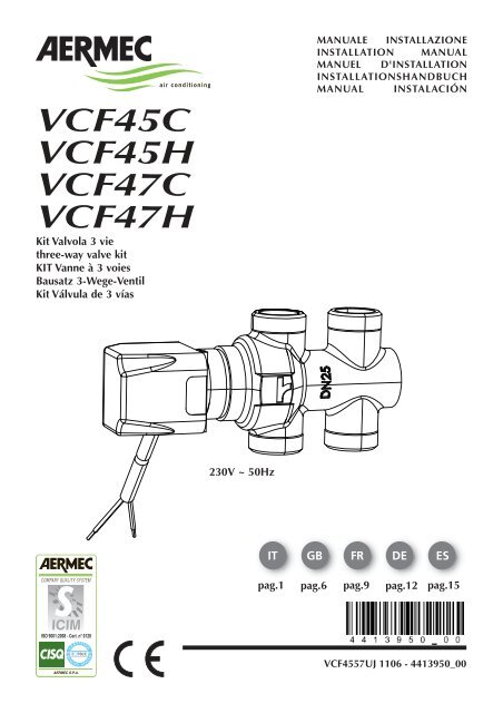
Three-way valve kit Aermec VCF 45C-45H 47C-47H Installation ...
Three-way valve kit Aermec VCF 45C-45H 47C-47H Installation ...
Three-way valve kit Aermec VCF 45C-45H 47C-47H Installation ...

Create successful ePaper yourself
Turn your PDF publications into a flip-book with our unique Google optimized e-Paper software.
<strong>VCF</strong><strong>45C</strong><br />
<strong>VCF</strong><strong>45H</strong><br />
<strong>VCF</strong><strong>47C</strong><br />
<strong>VCF</strong><strong>47H</strong><br />
Kit Valvola 3 vie<br />
three-<strong>way</strong> <strong>valve</strong> <strong>kit</strong><br />
KIT Vanne à 3 voies<br />
Bausatz 3-Wege-Ventil<br />
Kit Válvula de 3 vías<br />
230V ~ 50Hz<br />
MANUALE INSTALLAZIONE<br />
INSTALLATION MANUAL<br />
MANUEL D'INSTALLATION<br />
INSTALLATIONSHANDBUCH<br />
MANUAL INSTALACIÓN<br />
IT GB FR DE ES<br />
pag.1 pag.6 pag.9 pag.12 pag.15<br />
<strong>VCF</strong>4557UJ 1106 - 4413950_00
DESCRIPTION<br />
<strong>VCF</strong><strong>45C</strong> / <strong>VCF</strong><strong>47C</strong> are <strong>kit</strong>s made up of an insulated 3-<strong>way</strong> <strong>valve</strong> with 4<br />
connections, an electrothermal actuator and related fittings. They are<br />
suitable for installation on VED fan coils with both right and left connections.These<br />
are three-<strong>way</strong> <strong>valve</strong>s and 4 all or nothing type connections,<br />
normally closed, with by-pass flow control fitted as a mixer with G 3/4"<br />
Male flat fittings, powered at 230V ~50Hz The <strong>valve</strong>s can be controlled<br />
by the control panels (accessory) which are enabled for the <strong>valve</strong> checking<br />
function. Consult the control panel characteristics before selecting<br />
a panel. The <strong>VCF</strong><strong>45C</strong> / <strong>VCF</strong><strong>47C</strong> <strong>kit</strong>s must be installed on the main coil<br />
and are compatible with VED sizes:<br />
<strong>VCF</strong><strong>45C</strong>: VED430, VED432, VED440, VED441, VED530, VED532,<br />
VED540, VED541<br />
<strong>VCF</strong><strong>47C</strong>: VED630, VED632, VED640, VED641, VED730, VED732,<br />
VED740, VED741<br />
<strong>VCF</strong><strong>45H</strong> / <strong>VCF</strong><strong>47H</strong> are <strong>kit</strong>s made up of a three-<strong>way</strong> <strong>valve</strong> with 4 connections,<br />
an electrothermal actuator and related fittings. They are suitable<br />
for installation on VED fan coils with both right and left connections.<br />
These are three-<strong>way</strong> <strong>valve</strong>s and 4 all or nothing type connections, normally<br />
closed, with by-pass flow control fitted as a mixer with G 3/4<br />
"Male flat fittings, powered at 230V ~50Hz.The <strong>valve</strong>s can be controlled<br />
by the control panels (accessory) which are enabled for the <strong>valve</strong> checking<br />
function. Consult the control panel characteristics before selecting<br />
a panel. The <strong>VCF</strong><strong>45H</strong> / <strong>VCF</strong><strong>47H</strong> <strong>kit</strong>s must be installed on the secondary<br />
heating only coil and are compatible with VED sizes:<br />
<strong>VCF</strong><strong>45H</strong>:VED432, VED441, VED532, VED541<br />
<strong>VCF</strong><strong>47H</strong>:VED632, VED641, VED732, VED741<br />
<strong>VCF</strong><strong>45C</strong>/ <strong>VCF</strong><strong>47C</strong> KIT COMPONENTS:<br />
1 three-<strong>way</strong> <strong>valve</strong> and 4 connections<br />
1 Electrothermal actuator<br />
3 Connection pipes<br />
3 Flat seals<br />
2 O-Ring seals<br />
1 Insulating shell<br />
4 Self-locking clamps<br />
1 Probe holder clip<br />
<strong>VCF</strong><strong>45H</strong>/ <strong>VCF</strong><strong>47H</strong> KIT COMPONENTS:<br />
1 three-<strong>way</strong> <strong>valve</strong> and 4 connections<br />
1 Electrothermal actuator<br />
3 Connection pipes<br />
2 O-Ring seals<br />
3 Flat seals<br />
2 Self-locking clamps<br />
1 Probe holder clip<br />
DECLARATION OF CONFORMITY<br />
See the Declaration of Conformity of the VED unit<br />
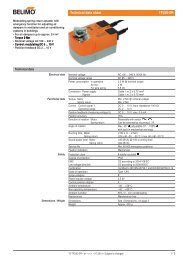
TECHNICAL SPECIFICATIONS<br />
Power supply: 230V (±10%) ~ 50Hz<br />
Initial peak current: 0.25A x 0.5s<br />
Input operating power: 2.5W<br />
Water temperature range: 4°C ÷ 80°C<br />
Usable liquids: water (with glycol 50%)<br />
Initial opening time: 90s<br />
Final opening time: 180s<br />
Maximum working pressure applied<br />
to the fan coils: 800kPa<br />
Environmental operating conditions<br />
Temperature: 0°C ÷ 40°C<br />
Environmental storage conditions<br />
Temperature: -25°C ÷ 60°C<br />
Protection level<br />
of the electrothermal actuator: IP44<br />
6<br />
A<strong>VCF</strong>4547UJ _ 1106 - 4413950_00<br />
Protection class<br />
of the electrothermal actuator: Type II<br />
Electrothermal actuator with threaded ring nut: M30 x 1.5<br />
Power cable: <strong>VCF</strong><strong>47C</strong> / <strong>VCF</strong><strong>47H</strong> L=2200mm 2 x 0.75mm 2<br />
<strong>VCF</strong><strong>45C</strong> / <strong>VCF</strong><strong>45C</strong> L=2000mm 2 x 0.75mm 2<br />
Model<br />
Valve body<br />
<strong>VCF</strong><strong>45C</strong> / <strong>VCF</strong><strong>47C</strong> <strong>VCF</strong><strong>45H</strong> / <strong>VCF</strong><strong>47H</strong><br />
Connectors G 3/4" male G 3/4" male<br />
Seal<br />
Connection pipes<br />
Valve side<br />
Flat Flat<br />
Coil inlet connections G 3/4" Female G 3/4" Female<br />
Seal<br />
Unit side<br />
Flat Flat<br />
Connectors G 3/4" male G 1/2" male<br />
Seal<br />
Pressure drop<br />
O-Ring O-Ring<br />
Kvs AB-A 4 4<br />
B - AB (By-pass) 1.7 1.7<br />
Dp =<br />
CALCULATION OF THE PRESSURE DROP<br />
((<br />
10 q<br />
Kvs<br />
2 p [kPa] = Pressure drop<br />
q [m 3 /h] = Water flow rate<br />
VALVE ASSEMBLY DIAGRAM (MIXER)<br />
AB<br />
A<br />
B<br />
OUT<br />
IN<br />
A-AB <strong>way</strong> of the <strong>valve</strong> is closed, while the by-pass <strong>way</strong> (B-AB) is<br />
open. With the electrothermal actuator powered, the actuator indicator<br />
is red.<br />
A-AB <strong>way</strong> of the <strong>valve</strong> is open, while the by-pass <strong>way</strong> (B-AB) is closed.<br />
With the electrothermal actuator powered, the actuator indicator is<br />
black.<br />
MAIN<br />
COIL<br />
SW<br />
SYSTEM EXAMPLE<br />
2-PIPE SYSTEM<br />
<strong>VCF</strong><strong>45C</strong><br />
<strong>VCF</strong><strong>47C</strong><br />
MAIN<br />
COIL<br />
<strong>VCF</strong><strong>45C</strong><br />
<strong>VCF</strong><strong>47C</strong><br />
With water sensor in the coil With water sensor upstream of the <strong>valve</strong><br />
SW
SECONDARY<br />
COIL<br />
ONLY<br />
HEATING<br />
MAIN<br />
COIL<br />
MAIN<br />
COIL<br />
SW<br />
<strong>VCF</strong><strong>45H</strong><br />
<strong>VCF</strong><strong>47H</strong><br />
Without water sensor<br />
<strong>VCF</strong><strong>45C</strong><br />
<strong>VCF</strong><strong>47C</strong><br />
SECONDARY<br />
COIL<br />
ONLY<br />
HEATING<br />
MAIN<br />
COIL<br />
<strong>VCF</strong><strong>45C</strong><br />
<strong>VCF</strong><strong>47C</strong><br />
<strong>VCF</strong><strong>45H</strong><br />
<strong>VCF</strong><strong>47H</strong><br />
<strong>VCF</strong><strong>45C</strong><br />
<strong>VCF</strong><strong>47C</strong><br />
With water sensor in the coil With water sensor upstream of the <strong>valve</strong><br />
SECONDARY<br />
COIL<br />
ONLY<br />
HEATING<br />
MAIN<br />
COIL<br />
4-PIPE SYSTEM<br />
<strong>VCF</strong><strong>45H</strong><br />
<strong>VCF</strong><strong>47H</strong><br />
Without water sensor<br />
<strong>VCF</strong><strong>45C</strong><br />
<strong>VCF</strong><strong>47C</strong><br />
Key:<br />
SW Water temperature sensor (ACCESSORY)<br />
<strong>VCF</strong><strong>45C</strong> / <strong>VCF</strong><strong>47C</strong> Main coil three-<strong>way</strong> <strong>valve</strong><br />
<strong>VCF</strong><strong>45H</strong> / <strong>VCF</strong><strong>47H</strong> Secondary heating only coil three-<strong>way</strong> <strong>valve</strong><br />
CAUTION:check that the power supply is disconnected before<br />
performing operations on the unit.<br />
WARNING:electrical connections, the installation of the fan coils<br />
and their accessories must only be carried out by people with the proper<br />
technical and professional qualifications for the installation, conversion,<br />
expansion and maintenance of the machinery and able to check that it<br />
is working properly and safe.<br />
In the specific case of electrical wirings, the following must be checked:<br />
- Measurement of the electrical system insulation strength.<br />
- continuity test of the protection wires.<br />
Before carrying out any intervention, use the necessary Personal<br />
Protective Equipment.<br />
Before installing the <strong>valve</strong> accessory <strong>kit</strong> consult the VED fan coil installation<br />
manual; it is the installer's job to prepare the water and electrical<br />
systems and to make the proper connections with the unit.<br />
The installation must be carried out in accordance with what is shown in<br />
the figure.<br />
WARNING! During installation, pay attention to the flow direction,<br />
before fitting the <strong>valve</strong>, check the installation direction referring to the<br />
embossed symbol on the <strong>valve</strong> body.<br />
SW<br />
Supplied O-Ring<br />
VED<br />
Cable grommet<br />
<strong>VCF</strong><strong>45C</strong>:<br />
<strong>VCF</strong><strong>47C</strong>:<br />
probe holder<br />
Supplied fl at seal 3/4<br />
<strong>VCF</strong><strong>45H</strong><br />
<strong>VCF</strong><strong>47H</strong><br />
Supplied 3/4 fl at seals<br />
<strong>VCF</strong><strong>45C</strong>:<br />
<strong>VCF</strong><strong>47C</strong>:<br />
Indicator: Red = Actuator not powered<br />
Black = Actuator powered<br />
A<br />
A-B<br />
Insulating shell<br />
Supplied self-locking clamps<br />
A<strong>VCF</strong>4547UJ _ 1106 - 4413950_00<br />
B<br />
A<br />
7
INSTALLATION<br />
Fit the connection pipes supplied with the <strong>valve</strong> body. The seal is guaranteed<br />
by the supplied 3/4" fl at seals (Tightening torque 25÷50Nm)<br />
Fit the two outlet pipes from the fan coil together. The seal is guaranteed<br />
by the supplied 3/4" flat seal<br />
Fit the <strong>valve</strong> body with the connection pipes to the fan coil, the seal is<br />
guaranteed by the supplied O-Ring<br />
Remove any protective cap or handwheel from the <strong>valve</strong> body<br />
Tighten manually the ring nut of the electrothermal actuator on the<br />
<strong>valve</strong> body, so that the actuator indicator is pointing outwards<br />
On the <strong>VCF</strong><strong>45C</strong> / <strong>VCF</strong><strong>47C</strong> models, fix the insulating shell to the <strong>valve</strong><br />
body with the two supplied clamps. Complete the insulation of the<br />
<strong>valve</strong>, any joints and pipes that may be uncovered. The isolation is<br />
especially important in circuits with cold water to avoid the formation<br />
of condensation and any drips.<br />
Insert the power cable into the electrothermal actuator through the<br />
cable gland on the side of the fan coil. Pass through the ventilation<br />
compartment fixing the cable on the appropriate cable clips of the<br />
shrouds. Exit the opposite side through the appropriate cable gland.<br />
Electrical wirings<br />
Connect the <strong>valve</strong> electrical cable to the unit control board or control<br />
panel as indicated in the wiring diagrams attached to the fan coil or the<br />
control panel manuals.<br />
System side water connections<br />
Perform the water connections (system side) on the <strong>valve</strong> with 3/4" flat<br />
seals (not supplied).<br />
8<br />
A<strong>VCF</strong>4547UJ _ 1106 - 4413950_00
<strong>VCF</strong><strong>45C</strong> <strong>VCF</strong><strong>45H</strong><br />
VED 4 5<br />
478<br />
436<br />
18<br />
G3/4”<br />
<strong>VCF</strong><strong>45H</strong><br />
G3/4”<br />
103<br />
<strong>VCF</strong><strong>45C</strong><br />
29<br />
VED<br />
A<strong>VCF</strong>4547UJ _ 1106 - 4413950_00<br />
VED<br />
<strong>VCF</strong><strong>45H</strong><br />
<strong>VCF</strong><strong>45C</strong><br />
158 40<br />
158 40
<strong>VCF</strong><strong>47C</strong> <strong>VCF</strong><strong>47H</strong><br />
VED 6 7<br />
513<br />
498<br />
G3/4”<br />
<strong>VCF</strong><strong>47H</strong><br />
G3/4”<br />
26<br />
100<br />
<strong>VCF</strong><strong>47C</strong><br />
VED VED<br />
<strong>VCF</strong><strong>47C</strong><br />
247 40<br />
<strong>VCF</strong><strong>47H</strong><br />
207 40<br />
A<strong>VCF</strong>4547UJ _ 1106 - 4413950_00<br />
19
Los datos técnicos contenidos en este documento no son vinculantes.<br />
AERMEC se reserva la facultad de aportar, en cualquier momento, todas las modificaciones consideradas necesarias para la mejora del producto.<br />
Les données mentionnées dans ce manuel ne constituent aucun engagement de notre part. <strong>Aermec</strong> S.p.A. se réserve le droit de modifier à tous moments les<br />
données considérées nécessaires à l’amelioration du produit.<br />
Technical data shown in this booklet are not binding.<br />
<strong>Aermec</strong> S.p.A. shall have the right to introduce at any time whatever modifications deemed necessary to the improvement of the product.<br />
Im Sinne des technischen Fortsschrittes behält sich <strong>Aermec</strong> S.p.A. vor, in der Produktion Änderungen und Verbesserungen ohne Ankündigung durchzuführen.<br />
Los datos técnicos incluidos en el presente documento no son vinculantes.<br />
<strong>Aermec</strong> S.p.A. se reserva el derecho de realizar en cualquier momento las modificaciones que considere oportunas para la mejora del producto.<br />
AERMEC S.p.A.<br />
I-37040 Bevilacqua (VR) - Italia<br />
Via Roma, 996 - Tel. (+39) 0442 633111<br />
Telefax (+39) 0442 93730 - (+39) 0442 93566<br />
www .aermec. com