Pronomic PMX-1804FX Users manual - Musikhaus Kirstein
Pronomic PMX-1804FX Users manual - Musikhaus Kirstein
Pronomic PMX-1804FX Users manual - Musikhaus Kirstein

You also want an ePaper? Increase the reach of your titles
YUMPU automatically turns print PDFs into web optimized ePapers that Google loves.
<strong>PMX</strong> Series Mixer<br />
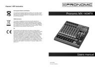
2.4 Rear view of <strong>PMX</strong>1204FX/<strong>PMX</strong>1404FX/<strong>PMX</strong>1604FX/<strong>PMX</strong><strong>1804FX</strong><br />
2.4.1 main mix outputs, Alt 3-4 outputs and control room outputs<br />
MAIN OUTPUTS ALT 3-4<br />
PIN 2 = HOT / PIN 3 = COLD OUTPUTS<br />
R L<br />
4<br />
12<br />
R L<br />
CONTROL ROOM OUT<br />
Fig. 2.14 Main mix outputs, Alt 3-4 outputs and control room outputs<br />
MAIN OUTPUTS<br />
The MAIN outputs carry the MAIN MIX signal and are on balanced XLR connectors with a nominal<br />
level of +4dBu.<br />
ALT 3-4 OUTPUTS<br />
The ALT 3-4 output are unbalanced and carry the signals of the channels that you have assigned to<br />
this group using the MUTE switch. This can be used to route a subgroup to a further mixing console for<br />
example, or it could be used as a recording output working in tandem with the main output. This means<br />
you could record to four tracks simultaneously. The icing on the cake, so to speak, is that you could<br />
connect Y-cables to these four outputs and then connect your 8-track recorder in such a way that you<br />
have 2 x 4 tracks. (E.g. Channel 1 feeds track 1and track 2, etc.). In the first recording pass, you record<br />
on track 1, 3.5 and 7 and in the second pass, on tracks 2, 4, 6 and 8.<br />
CONTROL ROOM OUTPUT<br />
The control room output is normally connected to the monitor system in the control room and provides<br />
the stereo mix or, when required, the solo signal.<br />
POWER<br />
PHANTOM<br />
ON<br />
ON<br />
AC 100-120V ~ 60Hz<br />
T10AH<br />
AC 200-240V ~ 50HZ<br />
T5AH<br />
Fig. 2.15: Voltage supply and fuse<br />
3<br />
<strong>PMX</strong>1404FX/<br />
<strong>PMX</strong>1604FX/<br />
<strong>PMX</strong><strong>1804FX</strong><br />
MAIN OUTPUTS ALT 3-4 OUTPUTS CONTROL ROOM OUT<br />
R L 4 3 R L<br />
PIN 2 = HOT / PIN 3 = COLD<br />
<strong>PMX</strong>1204FX<br />
2.4.2 Voltage supply, phantom power and fuse<br />
FUSE HOLDER<br />
The console is connect to the mains via the cable supplied<br />
which meets the required safety standards. blown fuses must<br />
only be replaced by fuses of the same type and rating.<br />
IEC MAINS RECEPTACLE<br />
The mains connection is via a cable with IEC mains connector.<br />
An appropriate mains cable is supplied with equipment.<br />
POWER<br />
Use the POWER switch to power up the mixing the console.<br />
PHANTOM<br />
The PHANTOM switch activates the phantom power supply for the XLR connectors of the mono channels<br />
which is required to operate condenser microphones. The red +48 VLED lights up when phantom<br />
power is on. As a rule, dynamic microphones can still be used with phantom power switched on, provided<br />
that they are wired in a balanced configuration. In case of doubt, contact the microphone manufacturer!<br />
1<br />
2<br />
- 8<br />
0<br />
- +15<br />
8<br />
0<br />
+15<br />
AUX<br />
POST<br />
PRE<br />
FX<br />
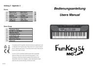
Fig. 2.3: The AUX SEND<br />
controls in the channel strips<br />
<strong>PMX</strong> Series Mixer<br />
2.1.3 Aux sends<br />
Aux sends take signals via a control from one or more<br />
channels and sum these signals to a so-called bus. This<br />
bus signal is sent to an aux send connector and then<br />
routed, for example, to an active monitor speaker or an<br />
external effects device. The return from an external effect<br />
device can then be brought back into the console via the<br />
aux return connectors.<br />
For situations which require effects processing, the aux<br />
sends are usually switched post-fader so that the effects<br />
volume in a channel corresponds to the position of the<br />
channel fader. if this were not the channel would remain<br />
audible even when the fader is turned to zero. When setting<br />
up a monitor mix, the aux sends are generally switched<br />
to pre-fader, i.e. they operate independently of the position<br />
of the channel fader.<br />
Both aux sends are mono, are sourced after the equalizer and offer up to +15dB gain.<br />
If you press the MUTE/ALT 3-4 switch, aux send 1 is muted, provided that it is switched postfader.<br />
However, this does not affect the aux send 2<br />
AUX 1 (MON)<br />
Aux send 1 can be switched pre-fader and is thus particularly suitable for setting up monitor mixes.<br />
PRE<br />
When the PRE switch is pressed, aux send 1 is sourced pre-fader.<br />
Aux 2 (FX)<br />
The aux send labeled FX is for sending to effects devices and is thus set up to be post-fader.<br />
If you wish to use the internal effects processor, the STEREO AUX RETURN 2 connectors<br />
should not be is use.<br />
You can also connect an external effects processor to aux send 2, however the internal<br />
effects module will be muted.<br />
L R<br />
1<br />
MUTE<br />
ALT 3-4<br />
dB<br />
10<br />
0<br />
10<br />
15<br />
20<br />
25<br />
30<br />
40<br />
60<br />
8<br />
PAN<br />
Fig. 2.4: Panorama and<br />
routing controls<br />
1<br />
MUTE<br />
CLIP<br />
SOLO<br />
2.1.4 Routing switch, solo and channel fader<br />
PAN<br />
The PAN control determines the position of the channel<br />
signal within the stereo image. This control features a<br />
constant-power characteristic, which means the signal is<br />
always maintained at a constant level, irrespective o position<br />
in the stereo panorama.<br />
MUTE/ALT 3-4<br />
You can use the MUTE/ALT 3-4 switch to driver the<br />
channel from the main mix bus to the Alt 3-4 bus. This<br />
mutes the channel from the main mix.<br />
MUTE-LED<br />
The MUTE LED indicates that the relevant channel is<br />
diverted to the submix (Alt 3-4 bus).<br />
5