Pronomic PMX-1804FX Users manual - Musikhaus Kirstein
Pronomic PMX-1804FX Users manual - Musikhaus Kirstein
Pronomic PMX-1804FX Users manual - Musikhaus Kirstein

You also want an ePaper? Increase the reach of your titles
YUMPU automatically turns print PDFs into web optimized ePapers that Google loves.
<strong>PMX</strong> Series Mixer<br />
8<br />
LEFT/MONO RIGHT<br />
1<br />
STEREO AUX RETURNS<br />
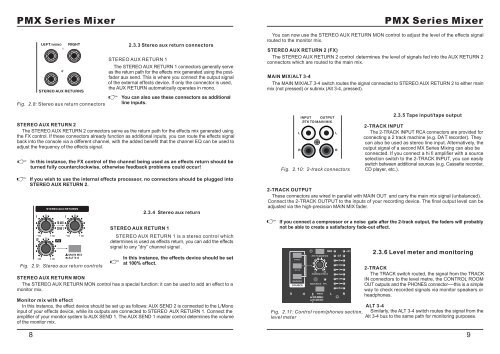
Fig. 2.8: Stereo aux return connectors<br />
2<br />
2.3.3 Stereo aux return connectors<br />
STEREO AUX RETURN 1<br />
The STEREO AUX RETURN 1 connectors generally serve<br />
as the return path for the effects mix generated using the postfader<br />
aux send. This is where you connect the output signal<br />
of the external effects device. If only the connector is used,<br />
the AUX RETURN automatically operates in mono.<br />
You can also use these connectors as additional<br />
line inputs.<br />
STEREO AUX RETURN 2<br />
The STEREO AUX RETURN 2 connectors serve as the return path for the effects mix generated using<br />
the FX control. If these connectors already function as additional inputs, you can route the effects signal<br />
back into the console via a different channel, with the added benefit that the channel EQ can be used to<br />
adjust the frequency of the effects signal.<br />
In this instance, the FX control of the channel being used as an effects return should be<br />
turned fully counterclockwise, otherwise feedback problems could occur!<br />
If you wish to use the internal effects processor, no connectors should be plugged into<br />
STEREO AUX RETURN 2.<br />
1<br />
8<br />
2<br />
8<br />
0<br />
0<br />
STEREO AUX RETURNS<br />
8<br />
8<br />
TO AUX<br />
SEND 1<br />
FX<br />
8<br />
Fig. 2.9: Stereo aux return controls<br />
1<br />
0<br />
8<br />
MAIN MIX<br />
ALT 3-4<br />
STEREO AUX RETURN 1<br />
2.3.4 Stereo aux return<br />
STEREO AUX RETURN 1 is a stereo control which<br />
determines is used as effects return, you can add the effects<br />
signal to any ”dry” channel signal .<br />
In this instance, the effects device should be set<br />
at 100% effect.<br />
STEREO AUX RETURN MON<br />
The STEREO AUX RETURN MON control has a special function: it can be used to add an effect to a<br />
monitor mix.<br />
Monitor mix with effect<br />
In this instance, the effect device should be set up as follows: AUX SEND 2 is connected to the L/Mono<br />
input of your effects device, while its outputs are connected to STEREO AUX RETURN 1. Connect the<br />
amplifier of your monitor system to AUX SEND 1. The AUX SEND 1 master control determines the volume<br />
of the monitor mix.<br />
<strong>PMX</strong> Series Mixer<br />
You can now use the STEREO AUX RETURN MON control to adjust the level of the effects signal<br />
routed to the monitor mix.<br />
STEREO AUX RETURN 2 (FX)<br />
The STEREO AUX RETURN 2 control determines the level of signals fed into the AUX RETURN 2<br />
connectors which are routed to the main mix.<br />
MAIN MIX/ALT 3-4<br />
The MAIN MIX/ALT 3-4 switch routes the signal connected to STEREO AUX RETURN 2 to either main<br />
mix (not pressed) or submix (Alt 3-4, pressed).<br />
L<br />
INPUT OUTPUT<br />
2TK TO MAIN MIX<br />
R<br />
Fig. 2.10: 2-track connectors<br />
L<br />
R<br />
2.3.5 Tape input/tape output<br />
2-TRACK INPUT<br />
The 2-TRACK INPUT RCA connectors are provided for<br />
connecting a 2 track machine (e.g. DAT recorder). They<br />
can also be used as stereo line input. Alternatively, the<br />
output signal of a second MX Series Mixing can also be<br />
connected. If you connect a hi fi amplifier with a source<br />
selection switch to the 2-TRACK INPUT, you can easily<br />
switch between additional sources (e.g. Cassette recorder,<br />
CD player, etc.).<br />
2-TRACK OUTPUT<br />
These connectors are wired in parallel with MAIN OUT and carry the main mix signal (unbalanced).<br />
Connect the 2-TRACK OUTPUT to the inputs of your recording device. The final output level can be<br />
adjusted via the high-precision MAIN MIX fader.<br />
If you connect a compressor or a noise gate after the 2-track output, the faders will probably<br />
not be able to create a satisfactory fade-out effect.<br />
2-TRACK<br />
ALT 3-4<br />
MAIN MIX<br />
SOURCE<br />
2TK TO MAIN MIX<br />
- +15<br />
PHONES/CTRL R<br />
8<br />
MAIN SOLO PFL<br />
3 4 MODE<br />
SOLO (NORMAL)<br />
PFL (LEVEL SET)<br />
POWER +48 V<br />
L R<br />
Fig. 2.11: Control room/phones section,<br />
level meter<br />
CLIP<br />
10<br />
5<br />
2<br />
0<br />
2<br />
5<br />
20<br />
2.3.6 Level meter and monitoring<br />
2-TRACK<br />
The TRACK switch routed, the signal from the TRACK<br />
IN connectors to the level metre, the CONTROL ROOM<br />
OUT outputs and the PHONES connector----this is a simple<br />
way to check recorded signals via monitor speakers or<br />
headphones.<br />
ALT 3-4<br />
Similarly, the ALT 3-4 switch routes the signal from the<br />
Alt 3-4 bus to the same path for monitoring purposes.<br />
9