Cover plate gaskets - Kempchen Dichtungstechnik GmbH
Cover plate gaskets - Kempchen Dichtungstechnik GmbH
Cover plate gaskets - Kempchen Dichtungstechnik GmbH

You also want an ePaper? Increase the reach of your titles
YUMPU automatically turns print PDFs into web optimized ePapers that Google loves.
07<br />
100<br />
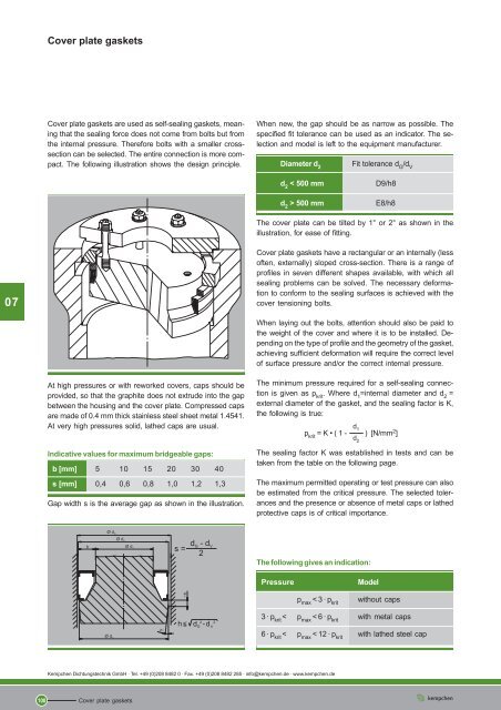
<strong>Cover</strong> <strong>plate</strong> <strong>gaskets</strong><br />
<strong>Cover</strong> <strong>plate</strong> <strong>gaskets</strong> are used as self-sealing <strong>gaskets</strong>, meaning<br />
that the sealing force does not come from bolts but from<br />
the internal pressure. Therefore bolts with a smaller crosssection<br />
can be selected. The entire connection is more compact.<br />
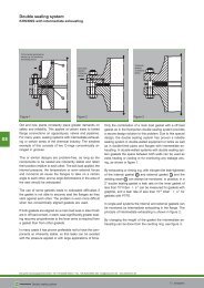
The following illustration shows the design principle.<br />
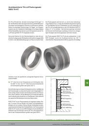
At high pressures or with reworked covers, caps should be<br />
provided, so that the graphite does not extrude into the gap<br />
between the housing and the cover <strong>plate</strong>. Compressed caps<br />
are made of 0.4 mm thick stainless steel sheet metal 1.4541.<br />
At very high pressures solid, lathed caps are usual.<br />
Indicative values for maximum bridgeable gaps:<br />
b [mm] 5 10 15 20 30 40<br />
s [mm] 0,4 0,6 0,8 1,0 1,2 1,3<br />
Gap width s is the average gap as shown in the illustration.<br />
<strong>Kempchen</strong> <strong>Dichtungstechnik</strong> <strong>GmbH</strong> · Tel. +49 (0)208 8482 0 · Fax. +49 (0)208 8482 285 · info@kempchen.de · www.kempchen.de<br />
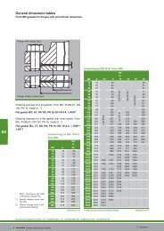
<strong>Cover</strong> <strong>plate</strong> <strong>gaskets</strong><br />
When new, the gap should be as narrow as possible. The<br />
specified fit tolerance can be used as an indicator. The selection<br />
and model is left to the equipment manufacturer.<br />
Diameter d 2<br />
Fit tolerance d G /d V<br />
d 2 < 500 mm D9/h8<br />
d 2 > 500 mm E8/h8<br />
The cover <strong>plate</strong> can be tilted by 1° or 2° as shown in the<br />
illustration, for ease of fitting.<br />
<strong>Cover</strong> <strong>plate</strong> <strong>gaskets</strong> have a rectangular or an internally (less<br />
often, externally) sloped cross-section. There is a range of<br />
profiles in seven different shapes available, with which all<br />
sealing problems can be solved. The necessary deformation<br />
to conform to the sealing surfaces is achieved with the<br />
cover tensioning bolts.<br />
When laying out the bolts, attention should also be paid to<br />
the weight of the cover and where it is to be installed. Depending<br />
on the type of profile and the geometry of the gasket,<br />
achieving sufficient deformation will require the correct level<br />
of surface pressure and/or the correct internal pressure.<br />
The minimum pressure required for a self-sealing connection<br />
is given as p krit . Where d 1 =internal diameter and d 2 =<br />
external diameter of the gasket, and the sealing factor is K,<br />
the following is true:<br />
d 1<br />
p krit = K • ( 1 - ) [N/mm 2 ]<br />
d 2<br />
The sealing factor K was established in tests and can be<br />
taken from the table on the following page.<br />
The maximum permitted operating or test pressure can also<br />
be estimated from the critical pressure. The selected tolerances<br />
and the presence or absence of metal caps or lathed<br />
protective caps is of critical importance.<br />
The following gives an indication:<br />
Pressure Model<br />
p max < 3 · p krit<br />
without caps<br />
3 · p krit < p max < 6 · p krit with metal caps<br />
6 · p krit < p max < 12 · p krit with lathed steel cap
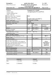
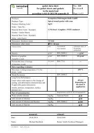
<strong>Cover</strong> <strong>plate</strong> <strong>gaskets</strong><br />
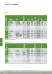
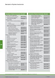
Construction and material of the gasket<br />
Graphite ring, Profile series P70<br />
made from chemically pure graphite, “RivaTherm”<br />
Factor K (N/mm2 )<br />
Material for the caps: Stainless steel sheet metal 1.4541 and/or<br />
by arrangement<br />
* Recommended maximum roughness depth of the flange<br />
surfaces<br />
Profile P71KL<br />
condition as received:<br />
condition under load:<br />
P71 P71K P71KL P74 P74K P75 P75K<br />
100 110 90 70 80 70 80<br />
<strong>Kempchen</strong> <strong>Dichtungstechnik</strong> <strong>GmbH</strong> · Tel. +49 (0)208 8482 0 · Fax. +49 (0)208 8482 285 · info@kempchen.de · www.kempchen.de<br />
<strong>Cover</strong> <strong>plate</strong> <strong>gaskets</strong><br />
R z*<br />
[µm]<br />
12,5<br />
to<br />
25<br />
1) In packing sets of two or more rings, the intermediate caps<br />
can be done away with, please specify when ordering.<br />
The pretensioning force FSV , which produces sufficient<br />
sealing surface pressure, can generally be represented as:<br />
2 d2 π pkrit FSV = •<br />
4 2<br />
Depending on the mode of operation, smaller or greater<br />
pretensioning forces can be indicated.<br />
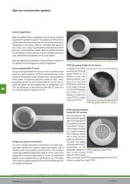
The P71KL model with U-shaped and L-shaped sheet metal<br />
cap or lathed steel cap has proven to be particularly good for<br />
sealing at high pressures. The cover has a slant of 26.5°,<br />
which extends to half of the sealing height. When fitted, the<br />
sealing ring is shaped into the slanted shape of the sealing<br />
space, generally giving approx. 12% radial compression.<br />
The advantage is that all sealing gaps required by the design,<br />
into which the graphite could be extruded, are closed off by<br />
the caps.<br />
The P71KL sealing ring combines the advantages of a<br />
sloped ring, i.e. low pre-deformative forces with the<br />
advantages of a plain compression ring, being easy to<br />
remove, particularly at high pressures and with large<br />
diameters.<br />
Equipment with d 2 = 720 mm diameter and 770 bar test<br />
pressure will run perfectly satisfactorily. Larger diameters of<br />
more than 1000 mm are used at approx. 500 bar and are<br />
just one further example of thousands of safely installed<br />
cover <strong>gaskets</strong>. To achieve an optimal seal h G should be =<br />
2 • b G .<br />
All rings are compressed in moulds. Our extensive range<br />
includes tools from a few millimetres to more than 1000 mm<br />
in diameter. As the moulds and tools are constantly being<br />
updated, an up-to-date list cannot be given here. We would<br />
be happy to advise whether a tool is available for the required<br />
measurement or whether it would cost extra.<br />
101<br />
07