Create successful ePaper yourself
Turn your PDF publications into a flip-book with our unique Google optimized e-Paper software.
H Y D R A U L I K<br />
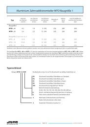
Planetary Gearboxes<br />
JPL and JPW<br />
April 2009<br />
<strong>Jahns</strong>-<strong>Regulatoren</strong> GmbH<br />
D 63069 Offenbach Sprendlinger Landstraße 150 Telefon +49 (0)69 848477-0<br />
D 63009 Offenbach Postfach 10 09 52 Telefax +49 (0)69 84847725<br />
http://www.jahns-<strong>hydraulik</strong>.de info@jahns-<strong>hydraulik</strong>.de
Index<br />
H Y D R A U L I K<br />
General information ..............................................................................................................................B. 3<br />
Construction options ........................................................................................................................B. 4-5<br />
Ordering code ..................................................................................................................................B. 12-13<br />
Symbols and units of measurement ........................................................................................... B. 17<br />
1. Technical defi nitions ......................................................................................................................B. 6<br />
1.1 Service factor ..........................................................................................................................B. 6<br />
1.2 Reduction ratio ......................................................................................................................B. 6<br />
1.3 Correction factor kf ..............................................................................................................B. 6<br />
1.4 Torque arm length ................................................................................................................B. 6<br />
1.5 Shrink disk torque .................................................................................................................B. 6<br />
1.6 Speed ........................................................................................................................................B. 6<br />
1.7 Lifetime .....................................................................................................................................B. 6<br />
Indicative values of the duration required for different applications.................B. 7<br />
1.8 Power ........................................................................................................................................B. 7<br />
Thermal factors ......................................................................................................................B. 7<br />
1.9 Torque .......................................................................................................................................B. 8<br />
1.10 Effi ciency ..................................................................................................................................B. 8<br />
2. Gearbox selection method ..........................................................................................................B. 8<br />
2.1 Selection ..................................................................................................................................B. 8<br />
Duration required by the FEM classes ...........................................................................B. 9<br />
2.2 Verifi cations ............................................................................................................................B. 9<br />
3. Motor selection method ............................................................................................................ B. 10<br />
3.1 Hydraulic drives .................................................................................................................. B. 10<br />
Average effi ciencies of hydraulic motors .................................................................. B. 10<br />
3.2 Electric drives ...................................................................................................................... B. 10<br />
4. Negative brakes ............................................................................................................................. B. 11<br />
4.1 Negative brakes .................................................................................................................. B. 11<br />
4.2 Brake selection .................................................................................................................... B. 11<br />
5. Assembly positions ...................................................................................................................... B. 11<br />
6. Ordering code ...........................................................................................................................B. 12-13<br />
7. Mounting instruction .................................................................................................................. B. 14<br />
7.1 Installation ............................................................................................................................ B. 14<br />
Tightening torques and clamping forces .................................................................. B. 14<br />
7.2 Lubrication ........................................................................................................................... B. 15<br />
7.3 Paint ........................................................................................................................................ B. 15<br />
7.4 Installation of fl ange motors ......................................................................................... B. 15<br />
7.5 Installation of motors with connection couplings ................................................ B. 15<br />
7.6 Weights .................................................................................................................................. B. 15<br />
8. Storage ................................................................................................................................................. B. 15<br />
9. Lubrifi cation ...................................................................................................................................... B. 16<br />
9.1 Type of lubricant ................................................................................................................ B. 16<br />
9.2 Choice of oil ......................................................................................................................... B. 16<br />
9.3 Oil changes .......................................................................................................................... B. 16<br />
9.4 Oil quantity .......................................................................................................................... B. 16<br />
Viscosity ................................................................................................................................. B. 16<br />
Recommended lubricants .............................................................................................. B. 16<br />
9.5 Temperature ........................................................................................................................ B. 16<br />
Symbols and units of measurement ........................................................................................... B. 17<br />
Page B. 2<br />
www.jahns-<strong>hydraulik</strong>.de
General information<br />
The new range of JPL planetary gearboxes, completed by the JPW line, enables<br />
<strong>Jahns</strong> to satisfy the needs of the modern market: more demanding and selective,<br />
dynamic, in constant evolution, requiring organization, simplicity, fl exibility, and<br />
technology. These are market qualities that our company is able to guarantee<br />
because the planetary line was designed around them by <strong>Jahns</strong> engineers; the<br />
life force of our company.<br />
The planetary gearbox presented in this catalogue, from 450 Nm to 1.205.000 Nm<br />
ISO torque and offer a wide range of reduction ratios from 3,5 to over 15000.<br />
Our gearboxes have been designed for the most selective applications; the large<br />
overloads in mobile applications as well as the long duration and reliability in<br />
industrial applications.<br />
In this catalogue we have increased the amount of support options, to satisfy the<br />
most extreme requirements.<br />
We introduced: foot mounted supports, shaft mounted outputs to complete the<br />
existing female splined output, keyed and cylindrical female, cylindrical male<br />
shafts, splined and hexagonal male shafts, and the integral shaft pinion which<br />
made us leaders in the small slewing drive market.<br />
The output accessories, coupling fl anges, splined or hexagonal bushes, splined<br />
bars, complete the output supports and enable easier adapting.<br />
The range of input accessories has also been enriched with supports, bevel<br />
gears, and new concept brakes. Our products work been successfully on mobile<br />
machines in transport and lifting markets, building, building yards, agricultural,<br />
and marine market sectors, as well as concrete pumps, crane trucks, cranes and<br />
aerial platforms.<br />
The planetary gearboxes are widely used in the following sectors: sheet metal<br />
working, iron and steel, plastic material, water purifi cation, chemical, energy,<br />
mineral and many other sectors.<br />
www.jahns-<strong>hydraulik</strong>.de<br />
Page B. 3<br />
H Y D R A U L I K
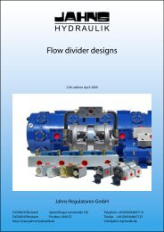
Construction options<br />
Motors<br />
1 - Electric motor<br />
2 - Orbital motor<br />
3 - Axial piston motor<br />
4 - Radial piston motor<br />
5 - Motor orbital "MGL"<br />
6 - Orbital motor "MGLR"<br />
7 - Orbital motor "MLG"<br />
8 - Orbital motor "MLR"<br />
Inputs<br />
9 - Motor fl ange adapter<br />
10 - Input shaft<br />
11 - Direct electric motor adapter<br />
12 - Direct orbital motor adapter<br />
13 - Negative brake "F1../F2.."<br />
14 - Negative brake "F5../F6.."<br />
15 - Standard input<br />
16 - Adaptor "MR"<br />
17 - Adaptor "MD"<br />
Reduction stages<br />
18 - Direct mount bevel gear<br />
19 - Input bevel gear<br />
20 - Single stage reduction<br />
21 - Double stage reduction<br />
22 - Triple stage reduction<br />
23 - Four stage reduction<br />
24 - Five stage reduction<br />
Output shaft and supports<br />
25 - Output support "N"<br />
26 - Output support "P"<br />
27 - Output support "T"<br />
28 - Output support "TR"<br />
29 - Output support "TL"<br />
30 - Output support "H"<br />
31 - Output support "F"<br />
32 - Output support "NQ"<br />
33 - Cylindrical output shaft<br />
34 - Splined output shaft<br />
35 - Hexagonal output shaft<br />
Reduction stages<br />
36 - Pinion "P"<br />
37 - Flange "FL"<br />
38 - Cylindrical bushing"BS"<br />
39 - Hexagonal bushing "ES"<br />
40 - Splined bar "BF"<br />
41 - Shrink disk "GA"<br />
42 - End plate "EP"<br />
43 - Oil expanxion tank<br />
H Y D R A U L I K<br />
Page B. 4<br />
www.jahns-<strong>hydraulik</strong>.de
www.jahns-<strong>hydraulik</strong>.de<br />
Page B. 5<br />
H Y D R A U L I K
1. Technical defi nitions<br />
1.1 Service factor<br />
fS = service factor:<br />
takes into account the gravity of the application; it depends on the:<br />
working conditions and type,<br />
type of operation,<br />
start-up frequency.<br />
fs • T2 < Tcont<br />
Service factor<br />
Type of load fs<br />
Uniform U Moderate M Heavy H<br />
Number of start- ups per hour 50 50 50<br />
Hydraulic motors 1,0 1,0 1,2 1,0 1,2 1,4 1,2 1,4 1,6<br />
Electric motors 1,1 1,2 1,4 1,2 1,4 1,6 1,4 1,6 1,8<br />
1.2 Reduction ratio<br />
ie = effective reduction ratio:<br />
ratio between the input and output velocity of the gearbox;<br />
ie = n1/n2 .<br />
1.3 Correction factor kf<br />
kf = output support lifetime correction factor:<br />
used to obtain the theoretic duration of the support for values of n2 h different from those found in the<br />
catalogue. For all gearboxes the external load curves are calculated for:<br />
- n2 h = 100.000 for the output supports<br />
- n1 h = 1.500.000 for the input supports<br />
1.4 Torque arm length<br />
Lmin= minimum advised torque arm length for shaft mounted applications.<br />
1.5 Shrink disk torque<br />
1.6 Speed<br />
Mtmax= maximum torque transmittable by the shrink disk when supplied by <strong>Jahns</strong>.<br />
Transmittable torque by the gearbox and the shrink disk must always be checked for compatibility.<br />
n1 = input velocity<br />
is the input velocity of the gearbox.<br />
n2max = maximum output velocity<br />
maximum output velocity of the gearbox for continuous operation; values of velocity near the maximum<br />
can be achieved in compatibility with the work cycle; for further information please contact thetechnical<br />
services.<br />
1.7 Lifetime<br />
n2 • h = output duration index:<br />
product of the output velocity and the duration in hours.It represents a number proportional to the<br />
stress applied to the element which limits the life of the gearbox. To correlate the velocity and the<br />
duration, the torque Tcont is expressed as a function of the product n2 • h.<br />
With the speed n2 and the torque Tcont required, the duration in hours can be calculated;or alternatively, if<br />
the speed and the duration in hours required are known then the Tcont that the gearbox can transmit<br />
can be calculated:<br />
H Y D R A U L I K<br />
Page B. 6<br />
www.jahns-<strong>hydraulik</strong>.de
Example:<br />
duration necessary in hours = 20.000<br />
output speed of the gearbox = 25 rpm<br />
20.000 [h] 25 [n2] = 500.000 [n2 • h]<br />
therefore a gearbox with a torque of 500.000 n2 • h corresponding to the torque required by the application<br />
will be selected. The same procedure is applied to diagrams of external loads, whilst knowing the application<br />
point of the load and its entity.<br />
n1 • h = input duration index:<br />
is the product of the input speed and the duration expressed in hours.<br />
It is used to calculate the duration of the bearings of the input supports.<br />
If you know velocity n1, the loads applied and the application point,<br />
the duration in hours can be obtained.<br />
Indicative values of the durations required for different applications<br />
Application Hours of life required<br />
Agricultural machines 300-3.000<br />
Machines which operate intermittently or forbrief periods (building machinerie) 3.000-8.000<br />
Machines which operate intermittently or forbrief periods with a high operative reliability (hoists) 8.000-12.000<br />
Machines which operate for 8 hours per day, but not fully utilised (various industrial machines, rotating crusher) 10.000-25.000<br />
Machines which operate for 8 hours per day, fully utilised (various industrial machines, conveyor belts) 20.000-30.000<br />
Machines operating continually (rolling mills, textile machines) 40.000-50.000<br />
1.8 Power<br />
Pt = thermal power:<br />
maximum mechanical power that the gearbox can transmit while operating continuously, with plash<br />
lubrication, without exceeding the thermal limit (oil temperature not greater than 90°C). Greater powers<br />
can be transmitted by using an appropriate cooling system. The value refers to a continual operation<br />
with mechanical effi ciency of 0,97 for each reduction stage, input velocity of 1500 rpm, ambient<br />
temperature of 20°C, altitude 0 / 500 m, application to the cover.<br />
For different conditions, the thermal power value must be multiplied by the thermal factors shown<br />
in the following table. For limited operating periods, followed by rest periods that are suffi ciently long to<br />
guarantee an adequate cooling of the gearbox, the thermal power loses its signifi cance and can be<br />
disregarded.<br />
Room temperature<br />
Thermal factors<br />
working time<br />
100% 80% 60% 40% 20%<br />
www.jahns-<strong>hydraulik</strong>.de<br />
10°C 1,2 1,3 1,4 1,6 1,8<br />
20°C 1,0 1,1 1,3 1,4 1,6<br />
30°C 0,8 1,0 1,1 1,3 1,4<br />
40°C 0,7 0,8 1,0 1,1 1,3<br />
50°C 0,5 0,7 0,8 1,0 1,1<br />
altitude input speed<br />
400 800 1000 1500 2000<br />
0 1,2 1,1 1,1 1,0 0,7<br />
500 1,2 1,1 1,1 1,0 0,7<br />
1.000 1,1 1,0 1,0 0,9 0,6<br />
1.500 1,1 1,0 1,0 0,9 0,6<br />
2.000 1,1 1,0 1,0 0,9 0,6<br />
Page B. 7<br />
H Y D R A U L I K
1.9 Torque<br />
Tiso = limit torque<br />
Transmittable torque of the gearbox, with continuous operation, calculated in accordance to ISO DP6336 for<br />
gears and safety factor of 1. This torque corresponds to a life duration equal to 50.106 cycles of the most stressed<br />
element (theoretically considered unlimited by the ISO DP6336; horizontal curve in the Wöhler fatigue diagram).<br />
This torque does not represent a duration, but it is useful for a quick selection of the maximum size of the<br />
gearbox.<br />
Tcont = continuous torque<br />
Transmittable torque of the gearbox, with continuous operation, that guarantees a duration of ‘h’ hours, with a<br />
gearbox output rotation velocity of ‘n2’ RPM. Tcont is expressed as a function of the product n2 h.<br />
Teq = equivalent torque<br />
Teq represents the value of a constant torque which determines the same duration in hours of the torque<br />
induced by the work cycle. Known as T21 … T2n the torque transmitted by the gearbox at the output velocity n2i<br />
for a time duration in hours of hi, the equivalent torque is:<br />
where<br />
Timp = impulsive torque<br />
value of the static torque or an istantaneous peak load that the gearbox can withstand.<br />
1.10 Effi ciency<br />
ηm = mechanical effi ciency:<br />
ratio between the output power and input power; normally it is considered to be equal to 0,97 – 0,98 per<br />
reduction stage that makes up the gearbox; it depends upon various factors, of which velocity, torque, ratio,<br />
working position and lubrication.<br />
2. Gearbox selection method<br />
2.1 Selection<br />
Once established the selection criteria, which can be defi ned using an ISO or AGMA safety factor, based upon the<br />
class according to the F.E.M. standard or by expressing a minimum life duration, the equivalent output torque Teq is<br />
determined as well as the required duration and the reduction ratio. Using these criteria the gearbox is selected.<br />
- safety factor ISO/AGMA:<br />
the gearbox must garantee the requested theoretical lifetime;<br />
- F.E.M. class:<br />
the gearbox must garanteee that the requested theoretical lifetime correspond to that indicated by the F.E.M.<br />
class as a function of the max and Teq;<br />
- life duration:<br />
the gearbox must have a life duration greater than that required as a function of Teq.<br />
For example, table... on page F.2 / F.9 shows the continuous torques as a function of gearbox size and the reduction<br />
ratio. Please note that when an electric motor is used, the start up torque can be 2.5 times greater than its nominal<br />
value.<br />
H Y D R A U L I K<br />
Page B. 8<br />
www.jahns-<strong>hydraulik</strong>.de
For the correct value please refer to the electric motor supplier’s catalogue (classes CEI 2–3/IEC34-1). The start<br />
up torque must not exceed the gearboxes maximum torque. The number of start-up per hour and the hours of<br />
operation per day must be carefully considered. If the output velocity is constantly less than 1 rpm, there may be<br />
problems with the lubrication of the output stage, which could reduce the calculated theoretical life. In this case it<br />
is advised that you contact the <strong>Jahns</strong> personnel for a proper selection.<br />
class<br />
<strong>Jahns</strong> waives all responsability of improper use of the selection criteria mentioned above, in particular for all<br />
applications subject to special rules and regulations (for example when personal safety is involved) and places this<br />
responsability on the application constructor. It is recommended that the constructor contact <strong>Jahns</strong> technical<br />
department for all such technical support.<br />
2.2 Verifi cations<br />
Gearbox output support:<br />
For each gearbox the dynamic radial loads according to ISO 281 for a duration of L10 corresponding to n2 h =<br />
100.000 are shown in the diagrams.<br />
For different durations, applicable radial loads can be obtained by multiplying the values in the diagrams by the<br />
correction factor kf.<br />
With regards to eventual axial loads, one must ensure that they do not exceed the maximum allowed values.<br />
www.jahns-<strong>hydraulik</strong>.de<br />
duration with<br />
Teq
Output torque:<br />
the output torque must never exceed Tmax. In the event that brakess are mounted on the gearbox or the motor,<br />
one must ensure that the braking torque does not exceed the maximum torque of the gearbox, itself multiplied<br />
by 1,1; with regards to the real braking torque, it is also necessary to consider the Effi ciency of the gearbox; see<br />
part 8.<br />
Input velocity:<br />
must not exceed the maximum gearbox input speed.<br />
Thermal power:<br />
in the event that the installed power is greater than the thermal power of the gearbox, it is necessary to provide a<br />
cooling circuit or to select a larger gearbox. The power to dissipate is:<br />
where P2 is the power transmitted by the gearbox. In the event that thermal power is not exceeded, but the<br />
application is particularly onerous, it may be necessary to install an oil circulation and fi ltering system.<br />
3. Motor selection method<br />
3.1 Hydraulic drives<br />
Knowing the hydraulic circuit pressure, from which the Dp of the motor can be obtained, the torque T1, the velocity<br />
n1 required at the input of the gearbox, the hydraulic motor capacity must be greater or equal to:<br />
where ηm is the mechanical effi ciency of the motor. The necessary supply fl ow rate is:<br />
where ηv is the volumetric effi ciency of the motor. Please use the following table as a guide for hydraulic motor<br />
selections.<br />
Hydraulic motors<br />
Use light medium heavy<br />
Pressure [bar]
4. Negative brakes<br />
4.1 Negative brakes<br />
The gearboxes can be supplied with a hydraulic negative brake:<br />
- The brakes from model F01 to model F26 are for the direct mounting of orbit motors with SAE A fl anges.<br />
- The brakes from model F501 to model F 612 reach greater braking torques and are mounted with a ST entrance<br />
for the mounting of fl anges and connecting couplings for a vast range of commercially available motors.<br />
- The brake models F813 to F830 achieve braking torques up to 3.050 Nm and come with the same direct input<br />
assembly as the JPL 310/510.<br />
- The MD brake is mounted directly into a connecting fl ange for the MLG - MLR motors on the JPL 110/JPL 240<br />
gearbox.<br />
Braking is generated by springs, which compress fi xed alternating tempered steel discs against bronze mobile<br />
discs; this thrust is transformed by friction into a braking torque. Brake releasing is achieved by the injection of<br />
hydraulic pressure into the brake; the pressure acts upon a piston, which compresses the springs, thus enabling the<br />
disc to rotate freely.<br />
The brakes are therefore static and closed when hydraulic pressure is zero and they open when the hydraulic<br />
pressure reaches the opening values for release. The brakes are not lubrifi cated by the oil from the gearbox. It is<br />
necessary to carry out the fi lling (approximately 0,1 l) with mineral oil of a viscosity ISO VG32; or as an alternative it<br />
is possible to use hydraulic oils.<br />
4.2 Brake selection<br />
The following parameters must be taken into consideration:<br />
- Braking torques are calculated with the pilot pressure = 0 bar; in the case of counter-pressures in the hydraulic<br />
circuit, the effective torque values are reduced as follows:<br />
Eff. Torque = Static Torque x (Opening pressure – Counter-pressure) / Opening pressure<br />
- The brake torque must be greater or equal to that of the motor:<br />
www.jahns-<strong>hydraulik</strong>.de<br />
Tf T 1<br />
- The brake torque multiplied by the reduction ratio and divided by the output of the gearbox, must be greater or<br />
equal to output torque:<br />
Tf • ie / ηm T 2<br />
- The brake torque multiplied by the reduction ratio and divided by the gearbox effi ciency must not exceed 90% of<br />
the impulse output torque of the gearbox.:<br />
Tf • ie / ηm 0,9 T 2imp<br />
5. Assemblypositions<br />
In order to provide a complete defi nition of the constructive form of the gearbox, the assembly position must be<br />
defi ned.<br />
Based upon the position it is also possible to identify the oil fi lling, level and drain plugs. See page G.236 - G.238.<br />
Page B. 11<br />
H Y D R A U L I K
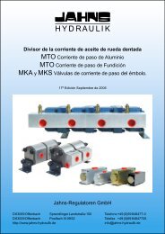
6. Ordering code<br />
JPW 21 3 P<br />
H Y D R A U L I K<br />
Output version<br />
Gearbox frame size<br />
Execution<br />
JPL = Linear JPW = Angular<br />
Number of stages<br />
1 - 2 - 3 - 4 - 5 - 6<br />
S 78<br />
Page B. 12<br />
Output shaft<br />
S = Male spline<br />
C = Cylindrical<br />
K = Extented cylindrical<br />
E = Hexagonal shaft<br />
Q = Hollow female shaft<br />
FS = Female spline<br />
BF = Female cylindrical<br />
Reduction ratio<br />
Please write the ratio as shown on the selection tables<br />
www.jahns-<strong>hydraulik</strong>.de
ST BB B3 0 BS<br />
www.jahns-<strong>hydraulik</strong>.de<br />
Output accessories<br />
Right angle positioning<br />
Mounting position<br />
Motor adapter confi guration<br />
Direct inputs<br />
Electric motor<br />
Orbit motor<br />
Axial-piston motor<br />
Radial-piston motor<br />
Page B. 13<br />
P = Pinion<br />
FL = Flange<br />
BS = Parallel bushing<br />
EP = End plate<br />
ES = Hexagonal bushing<br />
GA = Shrink disc<br />
VE = Oil expansion tank<br />
BF = Splined bar<br />
BR = Torque arm<br />
PH = Foot support<br />
The example shows the ordering code for a riht angle planetary gearbox, Frame 210 with 3 reductions stages, a foot mounted<br />
output support and a mal splined shaft, and 78.7 reductio ratio, with a "ST" input and "SAE B", 16/32 15 teeth motor adapter<br />
fl ange, horizontal mounting position and standad rigth angle positioning, and a paralell bushing output accessory.<br />
H Y D R A U L I K
7. Mounting instruction<br />
7.1. Installation<br />
Gearbox with fl ange and male shaft::<br />
The connecting surface should be fl at unpainted, machine tooled and at 90 degrees to the rotation axis. The<br />
following table shows the required spigots with their representative tolerances.<br />
Sizes up to JPL 6510: the spigots will have an H8 tolerance.<br />
H Y D R A U L I K<br />
Diameter mm 80-120 120-180 180-250<br />
Tolerance mm 0<br />
+0,054<br />
Diameter mm 500-630 630-800 800-1.000<br />
Tolerance mm +0,076<br />
+0,186<br />
Tightening torques and clamping forces<br />
Class 8.8 Class 10.9 Class 12.9<br />
Torque [Nm] Force [N] Torque [Nm] Force [N] Torque [Nm] Force [N]<br />
M10 50 27.000 70 39.000 85 46.000<br />
M12 85 39.500 120 57.000 145 67.000<br />
M14 136 54.500 195 78.000 230 92.000<br />
M16 213 75.000 310 105.000 360 127.000<br />
M18 300 93.500 420 130.000 495 153.000<br />
M20 430 120.000 600 165.000 700 195.000<br />
M22 580 148.000 810 210.000 965 245.000<br />
M24 730 170.000 1.000 240.000 1.200 285.000<br />
M27 1.080 225.000 1.500 315.000 1.800 370.000<br />
M30 1.470 270.000 2.050 385.000 2.450 455.000<br />
M33 2.000 335.000 2.750 460.000 3.300 550.000<br />
M36 2.550 390.000 3.500 535.000 4.500 645.000<br />
Page B. 14<br />
0<br />
+0,063<br />
+0,080<br />
+0,205<br />
0<br />
+0,072<br />
Diameter mm 250-315 315-400 400-500<br />
Tolerance mm 0<br />
+0,081<br />
Sizes from JPL 1520 version H to JPL 6020:<br />
These gearboxes are provided with two spigot diameters. It is suffi cient to create a single spigot on the structure<br />
when the radial loads on the output shaft are not present or when they are less than 50% of the maximum load<br />
permitted.<br />
0<br />
+0,089<br />
Size JPL 11000 and greater: the spigots will have an F8 tolerance.<br />
Gearboxes with female splined shaft:<br />
The female version gearboxes are not suitable for supporting output radial loads; it is therefore extremely<br />
important to properly align between the gearbox and the driven shaft. It is also necessary to check that the driven<br />
shaft does not undergo bending during the work phases.<br />
Foot mounted:<br />
The support surfaces must be level, and in axis with the machine being driven, to obtain this it is extremely<br />
important that the levelling and alignment operation is carried out carefully. An improper setting of the support<br />
base or an incorrect alignment can adversely affect the life of the gearbox.<br />
Shaft mounted gearbox with shrink disc:<br />
It is necessary to carry out an anchorage of the torque arm that is not constrained to the axis of the gearbox. The<br />
anchorage must also be suitable shock proof. In the dimensional tables of each gearbox one can fi nd the minimum<br />
torque arm lengths needed to carry out the application correctly.<br />
0<br />
+0,097<br />
+0,086<br />
+0,226<br />
www.jahns-<strong>hydraulik</strong>.de
7.2 Lubrication<br />
The gearboxes are supplied without oil.<br />
Before use, the gearbox must be fi lled with oil up to the level indicated using one of the lubricating oils advised.<br />
The choice and the quantity of oil will be referred to the installer/user based upon the type of application.<br />
7.3 Paint<br />
The supplied gearboxes are not painted. A few parts are treated with a base layer of water soluble epoxy ester red<br />
oxide. It is the responsibility of the customer to carry out the surface treatment using a paint that is compatible<br />
with the base layer. O-rings must be protected during the painting.<br />
7.4 Installation of fl ange motors<br />
The installation of the motors to the coupling fl ange supplied by <strong>Jahns</strong> is a particularly simple operation, but it<br />
must be carried out following the following important suggestions:<br />
-Lubricate the coupling with a light fi lm of grease or anti-seizure lubricant;<br />
-Ensure that the motor rests freely on the gearbox fi xing fl ange without forcing on either the shaft or the spigot;<br />
-Tighten screws.<br />
For further information refer to the maintenance and operation manual.<br />
7.5 Installation of motors with connection couplings<br />
When a connection coupling between motor and gearbox is used, one must verify that the alignment between<br />
the motor and the gearbox is compatible with the type of coupling. Couplings are widely used in industrial<br />
applications for the various functions that they can perform such as:<br />
- limit the input torque,<br />
- dampen vibrations coming from the motor,<br />
- compensate small misalignments.<br />
For the application of couplings, reference must be made to the component’s supplier operating manual.<br />
7.6 Weights<br />
For the gearboxes aproximative weights see page G.241.<br />
8. Storage<br />
The gearboxes must not be stored in the open or in direct contact with the ground. For long time periods they just<br />
be stored full of oil, with the external worked parts covered with grease and the coupling surfaces protected with<br />
anti-oxidant agents and operated under vacuum (a complete rotation of the output shaft is suffi cient) at least once<br />
every two months.<br />
For further information regarding storage, please refer to the maintenance and operating manual.<br />
www.jahns-<strong>hydraulik</strong>.de<br />
Page B. 15<br />
H Y D R A U L I K
9 . Lubrication<br />
9.1 Type of lubricant<br />
The gearbox lubrication is carried out by an oil bath; before the start-up of the gearbox it is necessary to fi ll it with<br />
oil, whilst ensuring visually using the level plug that the correct level is reached; this operation requires particular<br />
attention and the level must be re-checked after a few minutes of operation to ensure it has been carried out<br />
correctly. The quantities of oil shown in the catalogue are purely indicative and vary in function of the reduction<br />
ratio and the type of gearbox input.<br />
9.2 Choice of oil<br />
Any type of oil for mechanical transmissions can be use with EP additives that satisfy the VG68 and VG220 viscosity<br />
classes according to one following standards ISO 3448/SAE 80 - 90W/ SAE J 306-81; in particular cases, oils with<br />
different viscosities can be used, in this event please contact the technical services of <strong>Jahns</strong>. The oil viscosity must<br />
be chosen as a function of the ambient and working temperature of the gearbox. For gearboxes that have to<br />
operate at high ambient temperatures or where there are strong thermal fl uctuations, the use of synthetic based<br />
oils is recommended.<br />
In gearboxes with vertical assembly and continuous operation, the oil can undergo excessive overheating; in this<br />
event an external expansion tank is necessary (this can be supplied by <strong>Jahns</strong>) to enable the oil to expand due to<br />
thermal dilation.<br />
9.3 Oil changes<br />
The oil change must be carried out after the fi rst 150 hours of work, and then after the following 2000 or 4000<br />
hours of operation, depending on how the gearbox is used and at least once a year. To facilitate the emptying of<br />
the gearbox, we advise that the oil change is carried out while the gearbox is warm, the internal parts must be<br />
washed with suitable liquid before the introduction of new oil. Different oils must not be mixed together; this is<br />
particularly true of mineral and synthetic oils. After the gearbox has been operated, the lubricant level must be<br />
checked periodically and topping off arried out when necessary.<br />
9.4 Oil quantity<br />
The oil quantities required for proper lubrifi cation can be found in page G.239.<br />
SAE<br />
J-306-81<br />
H Y D R A U L I K<br />
VG<br />
ISO<br />
3448<br />
SAE 80W 68<br />
85WSAE90W 150<br />
SAE 220<br />
Viscosity<br />
Operating temperature<br />
Ambient temperature<br />
-20° -10° 0° 10° 20° 30° 40° 50° 60° 70° 80° 90° 100°<br />
Recommended lubricants<br />
producer mineral oil synthetik oil producer mineral oil synthetik oil<br />
AGIP Blasia Blasia S FINA Giran<br />
ARAL Degol BG Degol GS IP Mellana Telesia Oil<br />
BP Energol GR XP Enersyn HTX KLUBER Kluberoil GEM 1 Klubersynt GH6<br />
CASTROL Alpha SP Alpha SN MOBIL Mobilgear SHC<br />
CHEVRON NL Gear OPTIMOL Ultra<br />
DEA Falcon CLP Q8 Goya El Greco<br />
ELF Reductelf SP Elf Syntherma P SHELL Omala EP Tivela Oil<br />
ESSO Spartan Ep Glycolube TOTAL Carter EP<br />
9.5 Temperature<br />
The advised operating temperature of standard gearboxes should be between -15 deg.C. and + 40 deg. C.<br />
Page B. 16<br />
www.jahns-<strong>hydraulik</strong>.de
Symbol Unit Description<br />
Fr 2 N Output shaft radial loads<br />
Fa 2 N Outpur shaft axial loads<br />
Fr 1 N Input shaft radial loads<br />
Fa 1 N Input shaft axial loads<br />
fs - Service factor<br />
ie - Effective reduction ratio<br />
kf - Output support life correction factor<br />
L min mm Torque arm length<br />
Mt max Nm Shrink disk torque<br />
n 1 rpm Input speed<br />
n 1 • h rpm h Input duration index<br />
n 2 max rpm Maximum output speed<br />
n 2 rpm Output speed<br />
n 2 • h rpm h Output duration inex<br />
h h Hours<br />
hi - Percentage of time<br />
p bar Pressure<br />
P 1 kW Input power<br />
P 2 kW Output power<br />
P d kW Dissipated power<br />
Pt kW Thermal power<br />
Q l/min Oil fl ow<br />
Tf Nm Static braking torque<br />
T1 Nm Input torque<br />
T2 Nm Output torque<br />
Teq Nm Equivalent torque<br />
TISO Nm ISO limit torque<br />
T cont Nm Continuous torque<br />
Tmax Nm Maximum torque<br />
Timp Nm Impulse torque<br />
TM Nm Maximum load torque<br />
V cm³ Displacement<br />
X mm reaction distance<br />
ηm - Mechanical effi ciency<br />
ηv - Volumetric effi ciency<br />
ηt - Total yield<br />
Tb Nm Static breaking torque<br />
pb bar Total release pressure<br />
p max bar Maximum pressure<br />
n1 max rpm Maximimum speed<br />
www.jahns-<strong>hydraulik</strong>.de<br />
Symbols and units of measurement<br />
Page B. 17<br />
Symbol Description<br />
Output support<br />
Input<br />
Input support<br />
Tightening torque<br />
Oil quantity<br />
Weight<br />
Oil fi lling<br />
Oil level<br />
Oil draining<br />
Hydraulic motors<br />
Electric motors<br />
Recommend srews<br />
H Y D R A U L I K
Components for hydraulics and chemical engineering<br />
<strong>Jahns</strong>-<strong>Regulatoren</strong> GmbH Hausanschrift:<br />
Postfach 10 09 52 Sprendlinger Landstraße 150 http://www.jahns-<strong>hydraulik</strong>.de<br />
D 63009 Offenbach D 63069 Offenbach info@jahns-<strong>hydraulik</strong>.de<br />
Telefon +49/(0)69/84 84 77-0 Telefax +49/(0)69/84 84 77 25