Flow divider designs - Jahns-Regulatoren GmbH
Flow divider designs - Jahns-Regulatoren GmbH
Flow divider designs - Jahns-Regulatoren GmbH

You also want an ePaper? Increase the reach of your titles
YUMPU automatically turns print PDFs into web optimized ePapers that Google loves.
H Y D R A U L I K<br />
<strong>Flow</strong> <strong>divider</strong> <strong>designs</strong><br />
21th edition April 2009<br />
<strong>Jahns</strong>-<strong>Regulatoren</strong> <strong>GmbH</strong><br />
D 63069 Offenbach Sprendlinger Landstraße 150 Telephon +49 (0)69 848477-0<br />
D 63009 Offenbach Postbox 10 09 52 Telefax +49 (0)69 84847725<br />
http://www.jahns-hydraulik.de info@jahns-hydraulik.de
H Y D R A U L I K<br />
Contents<br />
<strong>Flow</strong>-<strong>divider</strong> applications<br />
Synchronised running ....................................................................................................................... 3<br />
Pressure multipliers ............................................................................................................................ 3<br />
Lubricating-oil fl ow <strong>divider</strong> ............................................................................................................. 3<br />
Synchronisation differences............................................................................................................ 4<br />
Internal pressure-drop....................................................................................................................... 4<br />
Means of overcoming the pressure-drop................................................................................... 4<br />
Using a “driver”...................................................................................................................................... 5<br />
Compensating synchronisation-errors........................................................................................ 5<br />
Minimum fl ows .................................................................................................................................... 5<br />
<strong>Flow</strong>-<strong>divider</strong> start-up ......................................................................................................................... 6<br />
Use fl ow <strong>divider</strong>s in special conditions ....................................................................................... 6<br />
Synchronisation ratios....................................................................................................................... 6<br />
Synchronisation errors due to differnt oil-compression ....................................................... 6<br />
Noise-levels ........................................................................................................................................... 6<br />
Inlet/outlet-blocks ............................................................................................................................. 6<br />
Use of other fl uids than mineraloil................................................................................................ 6<br />
How to install the fl ow <strong>divider</strong>, start-up ...................................................................................... 7<br />
Gear-fl ow-<strong>divider</strong>, high-pressure version ................................................................................... 7<br />
Volume-synchronisation-cylinder ................................................................................................. 7<br />
Technical datas, dimensions<br />
Series MK, valves for 2 sections<br />
Divider-valves MK size 1.................................................................................................................... 9<br />
Divider-valves MK size 2.................................................................................................................... 9<br />
Series MTO, for 2 up to 12 sections<br />
Gear fl ow-<strong>divider</strong> MTO-..-4 and MTO-..-5 ...........................................................................10, 11<br />
Gear fl ow-<strong>divider</strong> MTO-..-8 and MTO-..-31.........................................................................12, 13<br />
Gear fl ow-<strong>divider</strong> MTO-..-35 and MTO-..-80 ......................................................................14, 15<br />
Gear fl ow-<strong>divider</strong> MTO-..-110 bis MTO-..-150 ...................................................................16, 17<br />
Series MT-GM, only 2 sections ......................................................................................................24, 26<br />
Series MT-GM, only 2 sections, with EA valve block...........................................................27, 29<br />
Series MTL .............................................................................................................................................30, 31<br />
Series MTL, with EA valve block...................................................................................................32, 33<br />
Series STL, with EA valve block ....................................................................................................34, 35<br />
© <strong>Jahns</strong> <strong>Regulatoren</strong> <strong>GmbH</strong> 2004, 2005, 2006, 2007, 2009<br />
Reprinting, even partially, not permitted.<br />
No responsibility for possible errors in catalogues or other printed material is accepted.<br />
Former catalogues lost their validity.<br />
Catalogues are subject to be changed.<br />
Page 2<br />
www.jahns-hydraulik.de
Synchronised running<br />
If several motors or cylinders are operate from a single<br />
pump without any means of controlling their individual<br />
fl ows only the motor or cylinder with the lowest pressure<br />
requirement would start its work cycle. The motor<br />
or cylinder with the next lowest pressure requirement<br />
would only start when the fi rst unit has completed its<br />
work cycle. This mode of operation is generally undesirable<br />
and it is therefore necessary for the total pump<br />
fl ow to be divided into a series of partia fl ows.This can<br />
be achieved in the following ways:<br />
Throttles or fl ow regulation valves in each of the<br />
motor or cylinders connections.<br />
Oprerating the units in a series circuit.<br />
With fl ow <strong>divider</strong> valves for 2 sections.<br />
With fl ow <strong>divider</strong>s of various <strong>designs</strong>.<br />
<strong>Jahns</strong> fl ow <strong>divider</strong>s are of the rotating motor type and<br />
offer, indipendently of their design, the following synchronisation<br />
advantages:<br />
High degree of synchronisation even with the simpler<br />
gear-motor fl ow-<strong>divider</strong>s.<br />
High degree of synchronisation is maintained over<br />
a wide range of fl ows.<br />
Due to low leakage rates in the individual section<br />
the high degree of synchronisation is main-tained<br />
with differing load conditions.<br />
The use of fl ow <strong>divider</strong>s is not complicated if applied<br />
withan appropriate hydraulic circuit design. Ad di ti o nal<br />
installation alterations are not necessary.<br />
For applications, where only a lower degree of syn-chronisation<br />
is necessary, <strong>Jahns</strong> offers fl ow <strong>divider</strong> valves,<br />
too. These valves are a very economic al ter na ti ve. See<br />
page 8.<br />
Pressure multipliers<br />
As mentioned earlier as well as operating as a synchronising<br />
instrument the fl ow <strong>divider</strong> can be utilised as<br />
a pressure multiplier. The entire range of gear-motor<br />
fl ow <strong>divider</strong>s can be used for this type of application<br />
and due their low internal pressure losses and low cost<br />
they often represent the op ti mal solution.<br />
The cast-iron MTO range should be used when it is<br />
necessary to increase the output pressure to values<br />
around 280 bar. There is the option of requesting special<br />
versions with individual sections having varying absorption<br />
volumes. This enables pressures to be increased<br />
by a factor of three, four and more.<br />
www.jahns-hydraulik.de<br />
<strong>Flow</strong>-<strong>divider</strong> application<br />
Page 3<br />
The pressure values in the example diagramm below<br />
are indicative of an MT. The theoretical out-put pressure<br />
value of approx. 400 bar will be lower due to effi ency<br />
losses. It should be noted that the pressure gain achievedis<br />
made possible through an increase in system fl ow.<br />
This type of hydraulic circuit can be used where a low<br />
pressure circuit is already in use and where there is only<br />
need of small high pressure fl ow.<br />
The installation of a supplementary high pressure circuit<br />
with pump, electric motor, pressure relief valve and<br />
manometer would not be convient in this case as it<br />
would be possible to utilise the existing low pressure<br />
circuit.<br />
Q HD = 20 l/min<br />
V 1 = 115 cm³/rev<br />
Q E = 82 l/min<br />
p E = 100 bar<br />
p HD = 265 bar<br />
Lubricating-oil fl ow-<strong>divider</strong><br />
Q ND = 60 l/min<br />
V 2 = 350 cm³/rev<br />
Shafts with multiple sets of friction bearings require<br />
a sure supply of lubrifi cating oil in equal quantities to<br />
each of the bearings. With the gear-motor fl ow <strong>divider</strong>s,<br />
that do not have any external leakages, if the gear of<br />
one of the sections are turning then a synchronised<br />
fl ow in all the other sections is ensured. It is therefore<br />
only necessary to check the speed of on of the shafts<br />
with anelectronic sensor and <strong>Jahns</strong> can be supply the<br />
component required for this solution.<br />
H Y D R A U L I K
Synchronisation differences<br />
With particular reference to the gear-motor fl ow <strong>divider</strong>s<br />
MTO but also for the radial-motor fl ow <strong>divider</strong>s<br />
MT-GM and MTL synchronisation differences depend<br />
on the following parameters:<br />
Oil viscosity and temperature<br />
Pressure load varability<br />
System pressure levels<br />
Total fl ow rate to be divided<br />
Precise indications of synchronisation levels are only<br />
possible if the details of all the above parameters are<br />
known.<br />
A general indication may be obtained from the following<br />
values:<br />
MK under maximum oil-fl ow-values in the catalogue<br />
synchronisation tollerances ± 4,0 up to ± 5,0 %<br />
MTO Size 1 and 2 (aluminium housing)<br />
running more than 1200 rpm<br />
synchronisation tollerances ± 1,5 up to ± 2,0 %<br />
MTO Size 3 and 4 (cast iron housing)<br />
synchronisation tollerances ± 3 up to ± 4 %<br />
MT-GM synchronisation tollerances ± 0,5 up to ± 0,8 %<br />
MTL synchronisation tollerances ± 0,5 up to ± 0,8 %<br />
<strong>Jahns</strong> is able to carry out test-bench simulations of<br />
specifi ed working conditions in order to determine<br />
the synchronisation levels of a customer's particular<br />
application. In this way it is possible for the customer<br />
to avoid incorporating large “safety margins” in the<br />
design.<br />
Internal pressure drop in<br />
fl ow-<strong>divider</strong> valve.<br />
You fi nd the datas in the diagrams on page 8.<br />
Internal pressure drop in<br />
gear-motor fl ow-<strong>divider</strong>s<br />
The MTO geared fl ow <strong>divider</strong>s have an approximate<br />
pressure loss of 11-12 bar. Whilst the oil fl ow rate is a<br />
determining factor, it is possible that particular units<br />
will actually achieve values greater than those stated<br />
above.<br />
If it is important for you to know the actual value, please<br />
enquire providing details as regards the respective<br />
pressure, oil fl ow-rate and oil viscosity.<br />
H Y D R A U L I K<br />
<strong>Flow</strong>-<strong>divider</strong> application<br />
Page 4<br />
Internal pressure drop in<br />
radial-piston fl ow-<strong>divider</strong>s<br />
The radial piston motor design has larger pressure drops<br />
than the gear motor design and the pressure drop also<br />
depend on the outlet pressure. The following of the<br />
outlet pressure for all MT-GM an MTL models:<br />
Required Input Pressure<br />
output pressure pressure drop<br />
(bar) (bar) (bar)<br />
50 60 10<br />
100 120 20<br />
140 175 35<br />
150 190 40<br />
180 225 45<br />
190 240 50<br />
210 265 55<br />
230 285 55<br />
Pressure drop in radial-piston fl ow-<strong>divider</strong>s MT-GM and MTL<br />
Means of overcoming the<br />
disadvantage of pressure drop<br />
Often for cylinders the high pressure is only required<br />
in one fl ow direction. The fl ow <strong>divider</strong> can be built<br />
into the return line were the pressure is much lower.<br />
In several applications synchronisation is not required<br />
during the high pressure phase of the work<br />
cycle, for example, in a 2 cylinder press synchronisation<br />
is only needed when the cylinders are working<br />
at low pressure. During the high pressure phase of<br />
the work cycle the fl ow <strong>divider</strong> can be by-passed<br />
using check valves.<br />
Using a “driver”<br />
This is achieved by adding an extra section of equal or<br />
greater displacement to the fl ow <strong>divider</strong>. The return line<br />
of this section is connected directly to tank so that it<br />
in effect works as a motor for the other sections in the<br />
fl ow <strong>divider</strong> thereby increasing their outlet pressures.<br />
This is useful, for example, in lifting platforms that<br />
should lower under action of their own weight, but<br />
where the weight of the empty platform is insuffi cient<br />
for this to occur.<br />
www.jahns-hydraulik.de
Compensating synchronisation<br />
errors - installation of the fl ow<br />
<strong>divider</strong> in the hydraulic circuit<br />
As the low <strong>divider</strong> is an independent fl ow control<br />
mechanism without any direct means of measuring<br />
the synchronisations errors that will always occur, any<br />
corrections have to take place as the cylinders reach<br />
the end of their stroke.<br />
The diagramm below shows an example of such a<br />
circuit.<br />
The valves in the circuit have the following functions:<br />
The pressure relief valves 1 serve as protection against<br />
excess pressure in the cylinder outlet lines as may be<br />
caused by the pressure multiplier effect. In this way<br />
all cylinders are able to complete their strokes even<br />
if one of them has reached the stroke-end. Valves 2<br />
and 3 maintain a minimum pressure of approx. 4 bar<br />
in each of the fl ow <strong>divider</strong> sections. The difference of<br />
1 bar from the opening tension of valve 3 is due to the<br />
opening tension of valves 2 of 1 bar.<br />
The minimum pressure feed is important, for example,<br />
when one of the cylinder has reached its end stroke,<br />
but the fl ow <strong>divider</strong> continues running due to the slower<br />
cylinders. The pressure feed then prevents suction<br />
www.jahns-hydraulik.de<br />
<strong>Flow</strong>-<strong>divider</strong> application<br />
Page 5<br />
occuring in the line connecting the fastest cylinder.<br />
Valve 4 has an important function which is often ignored<br />
on fl ow <strong>divider</strong>s: If the oil fl ow from the pump<br />
reaches the cylinders and the fl ow <strong>divider</strong> has the task<br />
of collection the returnline oil in order to perform an<br />
equalisation of the fl ows, valve 4 ensures that the fl ow<br />
<strong>divider</strong> is not made to run at the speed of the fastest<br />
cylinder then the other cylinders do not follow due<br />
to friction, loading, pinching etc.: the fl ow <strong>divider</strong> can<br />
only operate as a collector if all the cylinders operate<br />
at the same speed.<br />
A pressure relief valve or an over-centre valve could be<br />
used instead of the throttle valve 4.<br />
The use of such a valve in the circuit becomes particularly<br />
important when the cylinder return strokes occur<br />
whitout a controlling pump fl ow, eg. under action of<br />
their own weight.<br />
Minimum fl ows<br />
The gear fl ow-<strong>divider</strong>s in particular are not low speed<br />
components. Generally the minimum fl ows per section<br />
are as follows:<br />
MTO : Qmin (l/min) = VKammer (cm3 /U) x 0.5<br />
Bei den Radialstromteilern gilt:<br />
MT-GM : Qmin = 0.15 x Qmax MTL : Qmin = 0.25 x Qmax <strong>Flow</strong> <strong>divider</strong> start-up<br />
The smallest fl ow <strong>divider</strong>s in particular do not start if<br />
there is already a high outlet pressure at the beginning<br />
of the cycle.<br />
This situation occurs, for example, with the fl ow <strong>divider</strong><br />
installed between the pump and cylinders, when the<br />
lifting of a load is stopped and held by pressure in the<br />
fl ow <strong>divider</strong> outlet.<br />
In this case it is possible to use check valves to hold the<br />
load while the fl ow <strong>divider</strong> outlets are relieved of pressure.<br />
Depending on the type of application a variety of<br />
solutions are possible; it is merely a question of taking<br />
this into consideration when designing the circuit.<br />
H Y D R A U L I K
Use of fl ow <strong>divider</strong>s in<br />
special conditions<br />
If the use of a fl ow <strong>divider</strong> is beeing considered, but it is<br />
not clear whether it will be suitable for the application,<br />
we recommend that you contact us and if possible send<br />
us the diagram of the proposed hydraulic circuit.<br />
The many years of experience of working together with<br />
our cliensts in the fi eld of fl ow <strong>divider</strong> applications enables<br />
us to expertly evalate any application.<br />
Use of other fl uids than mineraloil<br />
Specially the radial-piston fl ow <strong>divider</strong>s, but the fl ow<strong>divider</strong><br />
valves, too, accept other fl uids than mineraloil,<br />
such as HFC, HFD, non-contaminating fl uids. Please<br />
contact <strong>Jahns</strong> in those cases.<br />
Synchronisation ratios<br />
In general, the synchronisation ratio required is 1:1.<br />
Different ratios are possible on request. If so, please<br />
contact <strong>Jahns</strong> technical staff. Obtaining different ratios<br />
is made easier if it is possible to obtain the required<br />
section dis plac e ment difference in the same section<br />
housing.<br />
Synchronisation errors due to<br />
differing oil compression<br />
The fl ow <strong>divider</strong> is not able to compensate for errors<br />
due to differing oil compression caused by differing<br />
cylinder loads. It is advisable to minimise oil volumes<br />
between the fl ow <strong>divider</strong> and the cylinder by using<br />
short tubes of equal length for all cylinders. If the<br />
difference in load in the cylinders is unchanging then<br />
it is possible to correect or eliminate oil compression<br />
synchronisaton errors with the appropriate use of<br />
pressure relief valves.<br />
Noise-levels<br />
Specially the gear-motor fl ow <strong>divider</strong>s cause a noiselevel<br />
running over 1800 rpm that can not always be<br />
accepted. Please choice the displacement according<br />
to this fact.<br />
H Y D R A U L I K<br />
<strong>Flow</strong>-<strong>divider</strong> application<br />
Page 6<br />
Inlet / outlet-blocks<br />
To achieve a minimum of piping and fi ttings and to<br />
guarantee the proved quality of important valves for<br />
the hydraulic circuit, you can get from <strong>Jahns</strong> so called<br />
inlet/outlet blocks for MTZ, MT and MTL fl ow <strong>divider</strong>.<br />
They have to be ordered directly together with the fl ow<br />
<strong>divider</strong>s, because a later assembly is generally impossible<br />
or causes problems. The blocks for the MT series<br />
are not separated into inlet/outlet ports, but integrated<br />
in one block only.<br />
The present outlet-blocks have a relief-valve for each<br />
section and a separate port to measure the pressure.<br />
The pressure a setting should be done, when the cylinder<br />
are in the external stroke-end. The pressure-setting<br />
should be 20 bar over the pressure to lift the cylinder<br />
with their charge. The port NS, T should be coneccted<br />
with the return-line. This return-line should have a<br />
pretension of 3-5 bar.<br />
www.jahns-hydraulik.de
How to install the fl ow <strong>divider</strong>,<br />
start-up<br />
The use of MK-valves afford a horizontal assembly<br />
only. There are no further details to look for.<br />
Gear-motor fl ow-<strong>divider</strong>s MTO have no drain-line<br />
connection and, consequently, are not subject of<br />
prefi lling.<br />
The MT-GM-series require a drain-line connection<br />
to both sides. Max. drain-pressure is 1,5 bar.<br />
Radial-piston fl ow-<strong>divider</strong>s series MTL have a drainline<br />
connection on both end-sides. It's suffi cient to<br />
connect only one drain-line, because the drains of<br />
the sections are connected internally. Max. drainpressure<br />
is 10 bar (1,5 bar only for items with external<br />
shaft f. e. to measure the fl ow by the speed).<br />
Drain-line piping is to be installed in a way that it<br />
cannot get empty. Due to the low quantity of drain<br />
it is necessary to fi ll the radial-piston fl ow-<strong>divider</strong>s<br />
complete before the fi rst start. Otherwise the fl ow<strong>divider</strong><br />
has to run a long time with dry shaft and<br />
bearings. Specially this important detail is often<br />
forgoten even by skilled per so nal.<br />
Periods to change oil and fi lter: according to the<br />
recommendation of their suppliers.<br />
www.jahns-hydraulik.de<br />
<strong>Flow</strong>-<strong>divider</strong> application<br />
Further parts to synchronize oil-fl ows / oil-volumes<br />
Page 7<br />
H Y D R A U L I K
H Y D R A U L I K<br />
Divider-valves<br />
The valve produces 2 fl ows or riunifi es 2 fl ows. The total fl ow should lie between the<br />
minimum and maximum limits below. Within the fl ow-limits, the fl ow are nearly independant<br />
of oil-pressure and viscosity.<br />
Using this valve it's important to know that a stop of the fi rst fl ow causes a throttling<br />
of the second-one. This produces heat. Please take care of this fact.<br />
Generally we recommead the alloy-version, last not least due to the lower costs. Only<br />
a pressure of over 210 bar leads to the steel-version.<br />
Type<br />
Order-code<br />
Example: MKA-1/24<br />
Total fl ow<br />
minimal<br />
(l/min)<br />
Internal pressure-drop in fl ow-<strong>divider</strong>-valves<br />
Total fl ow<br />
maximal<br />
(l/min)<br />
Page 8<br />
Peak-pressure<br />
Type MKA<br />
(bar)<br />
24 max. total fl ow (l/min)<br />
1 Size<br />
MKA <strong>Flow</strong>-<strong>divider</strong> valve in alloy<br />
MKS <strong>Flow</strong>-<strong>divider</strong> valve in steel<br />
Circuit according DIN ISO 1219<br />
Peak-pressure<br />
Type MKS<br />
(bar)<br />
MKS-0 / 6 2 6 - 315<br />
MKA-1/12<br />
MKS-1/12<br />
4 12 210 350<br />
MKA-1/24<br />
MKS-1/24<br />
12 24 210 350<br />
MKA-1/40<br />
MKS-1/40<br />
24 40 210 350<br />
MKA-2/90<br />
MKS-2/90<br />
40 90 210 350<br />
MKA-2/150<br />
MKS-2/150<br />
90 150 210 350<br />
www.jahns-hydraulik.de
www.jahns-hydraulik.de<br />
Divider-valves<br />
Page 9<br />
Size 1<br />
Type E A Weight MKA Weight MKS<br />
MKA / MKS -1/12 G3/8" G3/8" 0,80 kg 1,85 kg<br />
MKA / MKS-1/24 G3/8" G3/8" 0,85 kg 1,90 kg<br />
MKA / MKS-1/40 G1/2" G3/8" 0,85 kg 1,90 kg<br />
Size 2<br />
Type E A Weight MKA Weight MKS<br />
MKA / MKS -2/90 G3/4" G1/2" 2,1 kg 4,4 kg<br />
MKA / MKS-2/150 G1" G3/4" 2,2 kg 4,5 kg<br />
H Y D R A U L I K
H Y D R A U L I K<br />
Aluminium MTO gear fl ow-<strong>divider</strong>s<br />
Cylinder fl ow-<strong>divider</strong>s are designed to bring about<br />
cylinder synchronisation. <strong>Jahns</strong> has been supplying a<br />
range of fl ow-<strong>divider</strong>s since 1980. For the last few years,<br />
in addition to the extremely precise but relatively<br />
expensive radial fl ow-<strong>divider</strong>s, the company has promoted<br />
a range of geared fl ow-<strong>divider</strong>s that have gained a<br />
reputation for their wide-ranging versatility.<br />
First the MTZ model made a name for itself. However, a<br />
few years ago it had to be withdrawn from sale abruptly,<br />
for reasons that require no further clarifi cation here. It<br />
was only when it was no longer available that it become<br />
clear how widely this model had been used.<br />
As the performance requirements of the <strong>divider</strong>s<br />
increased and surpassed the capabilities of the MTZ<br />
model, it resulted in the parallel development of the<br />
MTO model that is now available.<br />
In the meantime, we have developed our MTC devices<br />
to bridge the gap. The MTC already had many new features<br />
to distinguish it from the MTZ. However, it is only<br />
now with the advent of the MTO series that numerous<br />
technical features have been optimised.<br />
The new MTO series combines both aluminium devices<br />
for small absorption volumes with cast-iron fl ow-<strong>divider</strong>s<br />
for larger absorption volumes.<br />
A limited number of the former MHD and MTC devices<br />
will continue to be available for some time. The old<br />
catalogues referencing these products are still valid<br />
and continue to be available.<br />
The specifi c quality features of the MTO series (aluminium<br />
construction) are as follows:<br />
. Achieves a very high level of synchronisation. Whilst<br />
in our documentation we do indicate a greater degree<br />
of error, there are in fact applications where<br />
synchronisation errors of less than ± I % occur.<br />
Even when the individual cylinders have varying<br />
load pressures, the level of synchronisation achieved<br />
– ignoring the oil compression error – is still<br />
outstanding.<br />
. It is easy to extend the MTO unit up to 12 sections.<br />
This was not the case for example, for the MTC series<br />
that is still currently available and was regarded as<br />
a major disadvantage.<br />
. Facility of accommodating considerable differences<br />
in pressure between the individual sections. There<br />
are other construction types on the market that are<br />
less capable in this respect.<br />
. They incorporate the ‘EA7’ auxiliary valve blocks.<br />
These tried and tested blocks evolved from the MTZ<br />
Page 10<br />
series and are incorporated directly in the section<br />
housing. They offer the benefi ts of a much more<br />
competitive price and fewer points for po ten ti al oil<br />
leakage. These auxiliary valves are designed to protect<br />
the section between fl ow-<strong>divider</strong> and operating<br />
cylinder, which is otherwise not pressure-protected.<br />
An increase in pressure, particularly in the case of<br />
multi-<strong>divider</strong>s, can even become dangerous. In addition,<br />
it prevents the suction of air between two<br />
non-synchronised cylinders the non synchronised<br />
cylinders impel the fl ow-<strong>divider</strong> and suck oil from<br />
the oil sections of the cylinders that have already<br />
been synchronised.<br />
. For reasons of safety we still test each and every unit<br />
by means of load simulation and syn-chronisation<br />
measurement.<br />
. In some cases the permitted oil pressures have<br />
been considerably increased as compared to the<br />
MTZ series.<br />
. The inlets to each of the sections are co-joined internally;<br />
this was already the case with the MTC. Every<br />
second section has an inlet con-nector. This creates<br />
the option of larger oil fl ows, especially in the case of<br />
more than 5 sections, since it is possible to connect<br />
up more inlets. It is not necessary to have a separate<br />
inlet section (only a connection with no fl ow-<strong>divider</strong><br />
function), as was the case with the MTC.<br />
We have accommodated the considerable application<br />
scope of the old MTZ by introducing special sizes for<br />
absorption volumes of 4.8 and 11 cm3/rev to the new<br />
MTO. These sizes can be fi tted directly with the ‘EA7’ of<br />
the MTZ-..48 and MTZ-..M11 and are, therefore, interchangeable<br />
with the corres-ponding MTZ.<br />
In order to fi t these blocks to our MTO units, it is essential<br />
to mill down the lateral surfaces of the fl ow-<strong>divider</strong>s.<br />
This should be requested at time of order and is subject<br />
to a surcharge.<br />
www.jahns-hydraulik.de
The pressure valves were a key issue in the past. In the<br />
MTZ we had adjustable devices. This did not meet with<br />
the approval of a lot of customers, since the valves had<br />
to be adjusted on-site when installed on machines and<br />
often it was something that customers could have done<br />
without (”make it adjustable and it needs adjusting!“).<br />
Consequently, the subsequent MTC was fi tted with pressure<br />
valves, which were permanently set. This proved an<br />
ele gant and simple solution, particularly as we offered<br />
12 different fi xed values between 50 and 260 bar.<br />
The new pressure valves for the MTO represent a healthy<br />
compromise between the easily adjustable valves of<br />
the MTZ series and the non-adjustable valves of the<br />
MTC range.<br />
The drilled seating for the pressure valves in the MTC<br />
is the same as that for the new MTO valves. As a consequence<br />
it is still possible to pay extra in order to obtain<br />
devices with a fi xed value setting.<br />
The pressure control valves are set to these values.<br />
The fact that the pressure valves are counter-sunk<br />
means that it is not possible to adjust them, whilst at the<br />
same time looking at the pressure manometer. In order<br />
to set the valves it is necessary to remove the pressure<br />
cartridge from the block. Since the safety valves need<br />
not be set to a great degree of precision and can easily<br />
accommodate a tolerance of 3 bar, it is possible to set<br />
the valve by simply measuring the distance ‘L’ using a<br />
calliper rule. In the diagrams (left) you can read off the<br />
values for pressure = f(L) for the different springs. These<br />
tables indicate the pressure levels and the corresponding<br />
spring lengths. After installing the pressure control<br />
valves again, the adjustment is completed.<br />
www.jahns-hydraulik.de<br />
Integral pressure valves in the MTO<br />
Length L<br />
Page 11<br />
Standardspring, colour red, standard,<br />
preset to approx. 180 bar<br />
pressure<br />
(bar)<br />
Length L<br />
(mm)<br />
pressure<br />
(bar)<br />
Length L<br />
(mm)<br />
130 27,50 220 26,15<br />
140 27,35 230 26,05<br />
150 27,20 240 25,90<br />
160 27,05 250 25,80<br />
170 26,90 260 25,65<br />
180 26,75 270 25,55<br />
190 26,60 280 25,40<br />
200 26,45 290 25,25<br />
210 26,30 300 25,15<br />
Specialspring, colour green, preset to approx. 120 bar<br />
pressure<br />
(bar)<br />
Length L<br />
(mm)<br />
pressure<br />
(bar)<br />
Length L<br />
(mm)<br />
90 26,80 150 25,70<br />
100 26,60 160 25,55<br />
110 26,40 170 25,35<br />
120 26,25 180 25,20<br />
130 26,05 190 25,00<br />
140 25,90 200 24,80<br />
Specialspring, colour blue, preset to approx. 100 bar<br />
pressure<br />
(bar)<br />
Length L<br />
(mm)<br />
pressure<br />
(bar)<br />
Length L<br />
(mm)<br />
60 26,6 120 25,0<br />
70 26,3 130 24,8<br />
80 26,0 140 24,5<br />
90 25,8 150 24,2<br />
100 25,6 160 24,0<br />
110 25,3<br />
Specialspring, colour black, preset to approx. 50 bar<br />
pressure<br />
(bar)<br />
Length L<br />
(mm)<br />
pressure<br />
(bar)<br />
Length L<br />
(mm)<br />
30 26,2 60 25,3<br />
40 25,9 70 25,0<br />
50 25,6 80 24,7<br />
H Y D R A U L I K
Two different sizes of housing. Within each specifi c size<br />
the only difference between devices of varying absorption<br />
volumes is the width of the housing. It is possible<br />
to combine fl ow-<strong>divider</strong>s with all absorption volumes<br />
indicated below for each respective series. This is important<br />
when the cylinders have varying pressure loads<br />
and when the system is used as pressure booster.<br />
Following absorption volumes are available:<br />
Size 1<br />
4,2 cm3 /rev<br />
4,8 cm3 /rev (only special construction)<br />
5,5 cm3 /rev<br />
Size 2<br />
8,5 cm3 /rev<br />
11 cm3/rev (only special construction)<br />
14 cm3/rev 31,4 cm3 /rev<br />
Both series enable through-fl ows of between 2 l/min<br />
and 70 l/min per chamber. MTO cast-iron housings are<br />
used for larger through-fl ows. Specially constructed<br />
fl ow-<strong>divider</strong>s are only available with integral valves.<br />
They are designed to fi t the old ’EA7’ blocks from the<br />
MTZ range, in order to guarantee inter-changeability<br />
with the old model.<br />
The MTO series is designed for use with mineral oil<br />
according to DIN 51524. Please contact us in the case<br />
of other pressurised fl uids.<br />
The prescribed operating temperature range for normal<br />
seals is -25°C to +80°C and -25° C to +100° C when<br />
using viton seals.<br />
The recommended oil viscosity is between 12 and<br />
100 cSt, but maximum values up to 600 cSt are permitted.<br />
The system of fi ltration is a key factor, particularly in<br />
order to achieve a high level of synchronisation. Ultimately<br />
it is necessary to achieve the crucial metallic<br />
seal between the external surfaces of the gears and the<br />
internal bore of the housing. In any case, over the last<br />
few years the subject of fi ltration has no longer been<br />
an issue. The aim is understood as being not to reduce<br />
the level of fi ltration, but to emphasise the benefi ts of<br />
good fi ltration to the whole system. We recommend a<br />
nominal fi ltration fi neness of 10 µm, and an absolute<br />
value of 25 µm.<br />
In the version ‘A’ a pressure-limit and pre-fi ll valve per<br />
section are incorporated directly in the housing. The<br />
H Y D R A U L I K<br />
MTO Gear fl ow-<strong>divider</strong> (aluminium housing)<br />
Page 12<br />
pressure limit valves are adjustable. However, their<br />
incorporation as concealed devices is designed to<br />
prevent uncontrolled contortion during operation,<br />
whilst at the same time enabling adjustment, should<br />
this be necessary.<br />
Assembly-position of inputs and<br />
outputs MTO Size 1 and 2<br />
2<br />
3<br />
4<br />
5<br />
6<br />
7<br />
8<br />
9<br />
10<br />
11<br />
12<br />
www.jahns-hydraulik.de
www.jahns-hydraulik.de<br />
MTO Gear fl ow-<strong>divider</strong> (cast iron housing)<br />
Our MTO range of cast-iron fl ow-<strong>divider</strong>s has been<br />
available for a number of years and replaces our preceding<br />
MHD devices. The MHD series will continue to be<br />
available for the foreseeable future. However, it will be<br />
more expensive due to the smaller production runs. As<br />
a consequence, it is recommended to switch as soon as<br />
possible to the MTO cast-iron fl ow-<strong>divider</strong>. In addition<br />
to the more competitive price, the cast-iron MTO offers<br />
signifi cantly superior synchronisation values. Whilst it<br />
does not achieve the same synchronisation values as<br />
the aluminium <strong>divider</strong>s, it varies less from these ideal<br />
values than the previous MHD.<br />
Aluminium is in itself the ideal material for geared<br />
fl ow-<strong>divider</strong>s. In the process of running the devices in,<br />
the gears cut a little into the aluminium housing and<br />
create the so-called run-in groove. This optimises the<br />
crucial sealing between the gears and the housing: the<br />
internal leak oil transfer from chamber to chamber is<br />
invariably less than is the case, for example, with a castiron<br />
housing, for which such a process of running-in<br />
has much less of an effect.<br />
However, the properties of aluminium are such that:<br />
. There is less resistance to abrasive wear by particles<br />
in the oil = shortened life span.<br />
. In many industries (e.g. steel, shipbuilding) cast<br />
iron is most often either the preferred material or<br />
is mandatorily specifi ed.<br />
. There is a greater option of using operating fl uids<br />
other than mineral oil with cast-iron housings than<br />
is the case with aluminium housings.<br />
. Particularly in the case of large absorption volumes,<br />
the resistance of the cast-iron housing to pressure<br />
peaks can be better controlled.<br />
In the case of the cast-iron MTO series 3 the distances<br />
between the individual chambers is the same for all<br />
absorption volumes and identical to the dimensions of<br />
the previous MTZ-..51. This enables the use of the ‘EA7’ in<br />
and out block of the previous MTZ range. These blocks<br />
are made from aluminium. For series 3 and series 4 the<br />
„EA8“ steel inlet and outlet block is also available.<br />
Series 4 provides a nominal absorption volume of<br />
between 110 and 150 cm3 /rev and represents an upwards<br />
expansion of our range. A special device with an<br />
absorption value of 190 cm3 /rev is available on request,<br />
although it does have reduced pressure values.<br />
For the series 4 devices a special solution is provided<br />
by the incorporation of smaller sae ports in 6000 psi.<br />
Regrettably, the 3000 psi ports dominate the market<br />
Page 13<br />
for geared machines to such an extent that these are<br />
supplied as standard.<br />
At the intended lower speeds the robust housing<br />
construction can serve to reduce the noise level by<br />
several db(A).<br />
The sections of each unit of the cast-iron MTO are screw<br />
fi xed. The trans-sectional tie rods used in the MHD range<br />
are no longer required. The unavoidable consequence<br />
of this is a ‘tightening up’ of the cross-sectional area of<br />
each section. Whilst this may not look as elegant, the<br />
high stress resistance of the tie rods did result in higher<br />
strain loading. In the case of multi-<strong>divider</strong>s this necessitated<br />
either a reduction in pressure or the strengthening<br />
of both end sections by a ‘vice-like’, auxiliary structure<br />
in the machine.<br />
H Y D R A U L I K
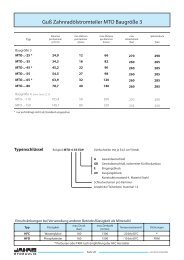
Type<br />
Order codes<br />
Example: MTO-4-5-AVR 4-section fl ow-<strong>divider</strong> with all section of 5,5 cm³/rev, pressure valve adjustable<br />
H Y D R A U L I K<br />
MTO Gear fl ow-<strong>divider</strong> (aluminium housing) Size 1<br />
Displacement<br />
per section<br />
(cm 3 /rev)<br />
min. fl ow<br />
per section<br />
(l/min)<br />
max. fl ow<br />
per section<br />
(l/min)<br />
Providing that the fl ow-noise is not an issue, it is possible to increase the pressure values in the chambers.<br />
AVR Pressure control valves adjustable from 130 to 300 bar, standard<br />
Spring colour red, preset to approx. 180 bar<br />
AVG Pressure control valves adjustable from 90 to 210 bar,<br />
Spring colour green, preset to approx. 120 bar<br />
AVB Pressure control valves adjustable from 60 to 120 bar,<br />
Spring colour blue, preset to approx. 100 bar<br />
AVS Pressure control valves adjustable from 30 to 80 bar,<br />
Spring colour black, preset to approx. 50 bar<br />
G Divider without additional valves, threaded connector<br />
5 Nominal displacement per chamber,<br />
actual displacement see above<br />
4 Number of part fl ows, maximum 12<br />
Page 14<br />
Continue<br />
pressure<br />
(bar)<br />
Peak<br />
pressure<br />
(bar)<br />
max. pressure difference<br />
between the<br />
sections outputs<br />
(bar)<br />
Size 1<br />
MTO-..-4 4,2 1,6 9 (10) 250 280 200<br />
MTO-..-5 5,5 2,2 12 (14) 230 250 200<br />
Size 2 Page16, 17<br />
MTO-..-8 8,16 3,5 19 (22) 250 280 200<br />
MTO-..-14 14,45 5,0 32 (39) 250 280 200<br />
MTO-..-31 31,4 12,5 62 (70) 210 240 200<br />
www.jahns-hydraulik.de
www.jahns-hydraulik.de<br />
MTO Gear fl ow-<strong>divider</strong> (aluminium housing) Size 1<br />
The drawing shows a 4-section fl ow-<strong>divider</strong>. Using more or less sections, you have to calculate the<br />
total length with a difference of B each section.<br />
Connections<br />
E1 to E2 G1/2" Input<br />
A1 to A4 G3/8" Output, divided fl ows<br />
T, NS G3/8" Tank and low-pressure-feeding<br />
Page 15<br />
MTO-..-..-G<br />
Weight: MTO-..-4-G 1,1 kg/section<br />
MTO-..-5-G 1,2 kg/section<br />
MTO-..-..-A...<br />
Weight: MTO-..-4-A 1,6 kg/section<br />
MTO-..-5-A 1,8 kg/section<br />
Circuit according DIN ISO 1219<br />
Type A1-4 E1-2 T/NS B C D F G H<br />
MTO-..-4<br />
MTO-..-5<br />
G3/8" G1/2" G3/8"<br />
80,4<br />
85,5<br />
50,7<br />
55,8<br />
342,2<br />
362,5<br />
50,5<br />
53,0<br />
410,2<br />
430,5<br />
84,5<br />
87,0<br />
H Y D R A U L I K
Type<br />
Size 1Page 14, 15<br />
Order codes<br />
H Y D R A U L I K<br />
MTO Gear fl ow-<strong>divider</strong> (aluminium housing) Size 2<br />
Displacement<br />
per section<br />
(cm 3 /rev)<br />
min. fl ow<br />
per section<br />
(l/min)<br />
max. fl ow<br />
per section<br />
(l/min)<br />
Providing that the fl ow-noise is not an issue, it is possible to increase the pressure values in the chambers.<br />
Example: MTO-4-8-AVR 4-section fl ow-<strong>divider</strong> with all section of 8,16 cm³/rev, pressure valve adjustable<br />
AVR Pressure control valves adjustable from 130 to 300 bar, standard<br />
Spring colour red, preset to approx. 180 bar<br />
AVG Pressure control valves adjustable from 90 to 210 bar,<br />
Spring colour green, preset to approx. 120 bar<br />
AVB Pressure control valves adjustable from 60 to 120 bar,<br />
Spring colour blue, preset to approx. 100 bar<br />
AVS Pressure control valves adjustable from 30 to 80 bar,<br />
Spring colour black, preset to approx. 50 bar<br />
G Divider without additional valves, threaded connector<br />
5 Nominal displacement per chamber,<br />
actual displacement see above<br />
4 Number of part fl ows, maximum 12<br />
Page 16<br />
Continue<br />
pressure<br />
(bar)<br />
Peak<br />
pressure<br />
(bar)<br />
max. pressure difference<br />
between the<br />
sections outputs<br />
(bar)<br />
MTO-..-4 4,2 1,6 9 (10) 250 280 200<br />
MTO-..-5 5,5 2,2 12 (14) 230 250 200<br />
Size 2<br />
MTO-..-8 8,16 3,5 19 (22) 250 280 200<br />
MTO-..-14 14,45 5,0 32 (39) 250 280 200<br />
MTO-..-31 31,4 12,5 62 (70) 210 240 200<br />
www.jahns-hydraulik.de
www.jahns-hydraulik.de<br />
MTO Gear fl ow-<strong>divider</strong> (aluminium housing) Size 2<br />
The drawing shows a 4-section fl ow-<strong>divider</strong>. Using more or less sections, you have to calculate the<br />
total length with a difference of B each section.<br />
Connections<br />
E1 to E2 Input<br />
A1 to A4 Output, divided fl ow<br />
T, NS Tank and low-pressure-feeding<br />
Page 17<br />
MTO-..-..-G<br />
Weight: MTO-..-8-G 2,1 kg/section<br />
MTO-..-14-G 2,6 kg/section<br />
MTO-..-31-G 3,5 kg/section<br />
MTO-..-..-A..<br />
Weight: MTO-..-8-A 2,7 kg/section<br />
MTO-..-14-A 3,4 kg/section<br />
MTO-..-31-A 4,5 kg/section<br />
Circuit according DIN ISO 1219<br />
Type A1-4 E1-2 T/NS B C D F G H<br />
MTO-..-8<br />
MTO-..-14<br />
G1/2" G3/4"<br />
G1/2"<br />
69,95<br />
87,95<br />
57,1<br />
75,1<br />
302,8<br />
374,8<br />
46,5<br />
55,5<br />
378,8<br />
450,8<br />
84,5<br />
93,5<br />
MTO-..-31 G3/4" G1" 114,95 102,1 482,8 69,0 558,8 107,0<br />
H Y D R A U L I K
Type<br />
Order codes Example: MTO-4-55-EA7 4-section fl ow-<strong>divider</strong> with all sections of 54,5 cm³/rev.<br />
H Y D R A U L I K<br />
MTO Gear fl ow-<strong>divider</strong> (cast iron housing) Size 3<br />
Displacement<br />
per section<br />
(cm 3 /U)<br />
Page 18<br />
G Threated connection<br />
GB Threated connection, for valve block assembly<br />
E Inlet block<br />
Restrictions in the use of other operating fl uids than mineral oil<br />
Type Fluid<br />
min. fl ow<br />
per section<br />
(l/min)<br />
max. pressure<br />
(bar)<br />
max. fl ow<br />
per section<br />
(l/min)<br />
A7 Outlet block, design series 7<br />
Displacement per section<br />
Number of section, maximum 8<br />
max. revs<br />
(rev/min)<br />
Continue<br />
pressure<br />
(bar)<br />
Peak<br />
pressure<br />
(bar)<br />
Size 3<br />
MTO-..-25 24,9 12 66 270 290<br />
MTO-..-35 34,3 16 82 260 285<br />
MTO-..-55 54,5 27 98 260 285<br />
MTO-..-80 78,7 40 140 260 285<br />
Size 4. Page 22, 23<br />
MTO-..-110 105,4 50 200 270 290<br />
MTO-..-150 149,7 80 220 235 250<br />
temperatur range seals<br />
HFC water glycol 160 1300 -20 bis 60°C *<br />
HFD phosphate esther 160 1500 -10 bis 60°C FKM<br />
* Perbunan oder FKM according to the HFC manufacturer's recommendation<br />
www.jahns-hydraulik.de
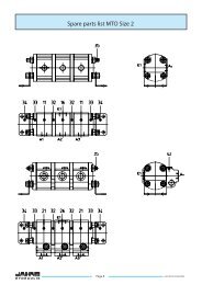
The drawing shows a 4-section fl ow-<strong>divider</strong>. Using more or less sections, you have to calculate the<br />
total length with a difference of 167,5 mm each section.<br />
Connections<br />
Connections<br />
E G1 1/4" Input<br />
A1 to A4 G1 1/4" Output, divided fl ows<br />
T, NS G1/2" Tank and low-pressure-feeding<br />
M1 to M4 G3/4" Measuring port for each section<br />
www.jahns-hydraulik.de<br />
MTO Gear fl ow-<strong>divider</strong> (cast iron housing) Size 3 EA7<br />
E G1 1/4" Input<br />
A1 to A4 G1 1/4" Output, divided fl ows<br />
Page 19<br />
MTO-..-..-G<br />
Weight: 30 kg/section<br />
MTO-..-..-EA7<br />
Weight: 34 kg/section<br />
Circuit according DIN ISO 1219<br />
Type A B C D<br />
MTO-..-35 130,0 37,5 110,0 471,5<br />
MTO-..-55 124,5 43,0 104,5 488,5<br />
MTO-..-80 109,0 58,5 89,0 504,0<br />
H Y D R A U L I K
Type<br />
Order codes Example: MTO-4-55-EA9 4-section fl ow-<strong>divider</strong> with all sections of 54,5 cm³/rev.<br />
H Y D R A U L I K<br />
MTO Gear fl ow-<strong>divider</strong> (cast iron housing) Size 3<br />
Displacement<br />
per section<br />
(cm 3 /U)<br />
Page 20<br />
G Threated connection<br />
GB Threated connection, for valve block assembly<br />
E Inlet block<br />
Restrictions in the use of other operating fl uids than mineral oil<br />
Type Fluid<br />
min. fl ow<br />
per section<br />
(l/min)<br />
max. pressure<br />
(bar)<br />
max. fl ow<br />
per section<br />
(l/min)<br />
A9 Outlet block, design series 9<br />
Displacement per section<br />
Number of section, maximum 8<br />
max. revs<br />
(rev/min)<br />
Continue<br />
pressure<br />
(bar)<br />
Peak<br />
pressure<br />
(bar)<br />
Size 3<br />
MTO-..-25 24,9 12 66 270 290<br />
MTO-..-35 34,3 16 82 260 285<br />
MTO-..-55 54,5 27 98 260 285<br />
MTO-..-80 78,7 40 140 260 285<br />
Size 4. Page 22, 23<br />
MTO-..-110 105,4 50 200 270 290<br />
MTO-..-150 149,7 80 220 235 250<br />
temperatur range seals<br />
HFC water glycol 160 1300 -20 bis 60°C *<br />
HFD phosphate esther 160 1500 -10 bis 60°C FKM<br />
* Perbunan oder FKM according to the HFC manufacturer's recommendation<br />
www.jahns-hydraulik.de
The drawing shows a 4-section fl ow-<strong>divider</strong>. Using more or less sections, you have to calculate the<br />
total length with a difference of 167,5 mm each section.<br />
Connections<br />
Connections<br />
E G1 1/4" Input<br />
A1 to A4 G1 1/4" Output, divided fl ows<br />
T, NS G1 1/4" Tank and low-pressure-feeding<br />
M1 to M4 G1/4" Measuring port for each section<br />
www.jahns-hydraulik.de<br />
MTO Gear fl ow-<strong>divider</strong> (cast iron housing) Size 3 EA9<br />
E G1 1/4" Input<br />
A1 to A4 G1 1/4" Output, divided fl ows<br />
Page 21<br />
MTO-..-..-G<br />
Weight: 30 kg/section<br />
MTO-..-..-EA9<br />
Type A B C D<br />
MTO-..-35 126,0 41,5 104,5 492,5<br />
MTO-..-55 124,5 43,0 104,5 505,5<br />
MTO-..-80 109,0 58,5 89,0 521,0<br />
Weight: 36 kg/section<br />
Circuit according DIN ISO 1219<br />
H Y D R A U L I K
Type<br />
Order codes<br />
H Y D R A U L I K<br />
MTO Gear fl ow-<strong>divider</strong> (cast iron housing) Size 4<br />
Displacement<br />
per section<br />
(cm 3 /U)<br />
Example: MTO-4-110-EA8 4-section fl ow-<strong>divider</strong> with all sections of 105,4 cm³/rev.<br />
Page 22<br />
S SAE 1 1/2" 3000 psi<br />
SB SAE 1 1/2" 3000 psi, for valve block assembly<br />
E Inlet block<br />
Restrictions in the use of other operating fl uids than mineral oil<br />
Type Fluid<br />
min. fl ow<br />
per section<br />
(l/min)<br />
max. pressure<br />
(bar)<br />
max. fl ow<br />
per section<br />
(l/min)<br />
A8 Outlet block, design series 8<br />
Displacement per section<br />
Number of section, maximum 8<br />
max. revs<br />
(rev/min)<br />
Cotinue<br />
pressure<br />
(bar)<br />
Peak<br />
pressure<br />
(bar)<br />
Size 3. Page 18, 21<br />
MTO-..-25 24,9 12 66 270 290<br />
MTO-..-35 34,3 16 82 260 285<br />
MTO-..-55 54,5 27 98 260 285<br />
MTO-..-80 78,7 40 140 260 285<br />
Size 4<br />
MTO-..-110 105,4 50 200 270 290<br />
MTO-..-150 149,7 80 220 235 250<br />
temperatur range seals<br />
HFC water glycol 160 1300 -20 bis 60°C *<br />
HFD phosphate esther 160 1500 -10 bis 60°C FKM<br />
* Perbunan oder FKM according to the HFC manufacturer's recommendation<br />
www.jahns-hydraulik.de
The drawing shows a 4-section fl ow-<strong>divider</strong>. Using more or less sections, you have to calculate the<br />
total length with a difference of B each section.<br />
Connections<br />
E1 to E2 SAE1 1/2" 6000 psi Input<br />
A1 to A4 SAE1 1/2" 6000 psi Output, divided fl ows<br />
T, NS G3/4" Tank and low-pressure-feeding<br />
M1 to M4 G3/8" Measuring port for each section<br />
www.jahns-hydraulik.de<br />
MTO Gear fl ow-<strong>divider</strong> (cast iron housing) Size 4<br />
Connections<br />
E1 to E4 SAE1 1/2" 3000 psi Input<br />
A1 to A4 SAE1 1/2" 3000 psi Output, divided fl ows<br />
Page 23<br />
MTO-..-...-S<br />
Circuit according DIN ISO 1219<br />
Weight: 45 kg/section<br />
MTO-..-...-EA8<br />
Weight: 65 kg/section<br />
Typ B C D F G H<br />
MTO-..-110 171 117 683,5 99,5 419 92<br />
MTO-..-150 187 133 747,5 102,5 387 95<br />
H Y D R A U L I K
Complete drawings of the assembled units of different sizes to be used as pressure-multipliers or fl ow-<strong>divider</strong>s are available<br />
upon request.<br />
Order Codes Example: MT-GM1-100/100-FG<br />
MT-GM1... / ...-FG<br />
Weight: 66 kg<br />
Type<br />
H Y D R A U L I K<br />
Radial piston fl ow <strong>divider</strong> MT-GM<br />
Displacement <strong>Flow</strong> per section Pressure Max poiwer<br />
per section continuous maximum continuous intermittend per section<br />
cm 3 /rev l/min l/min bar bar kW<br />
MT-GM1 100/100 99 35 50 240 300 24<br />
MT-GM1 175/175 172 70 100 240 300 30<br />
MT-GM2 350/350 347 120 175 240 300 45<br />
MT-GM2 500/500 493 145 210 240 300 45<br />
MT-GM3 800/800 792 235 280 240 300 60<br />
MT-GM5 1800/1800 1816 340 430 240 300 90<br />
MT-GM6 3000/3000 3041 430 550 240 300 120<br />
Page 24<br />
G Threated connection, see page 8<br />
F Feet, standard-supply without feet<br />
EA Inlet and outletblock<br />
Displacement of each section,see page 11<br />
GM1 Size<br />
Connections<br />
E1 - E2 G1" Input, to be connected together<br />
A1 - A2 G1" Output, section-flows<br />
L1 - L2 G1/4" Drain-ports, drain pressure max. 2 bar<br />
Important: both ports have to be connected to the tank !<br />
www.jahns-hydraulik.de
www.jahns-hydraulik.de<br />
Radial piston fl ow <strong>divider</strong> MT-GM<br />
Page 25<br />
MT-GM2... / ...-FG<br />
Connections<br />
E1 - E2 G1" Input, to be connected together<br />
A1 - A2 G1" Output, section-fl ows<br />
L1 - L2 G1/2" Drain-ports, drain pressure max. 2 bar<br />
Important: both ports have to be connected to the tank !<br />
MT-GM3... / ...-FG<br />
Connections<br />
E1 - E2 G1" Input, to be connected together<br />
A1 - A2 G1" Output, section-fl ows<br />
L1 - L2 G1/2" Drain-ports, drain pressure max. 2 bar<br />
Important: both ports have to be connected to the tank !<br />
Weight: 107 kg<br />
Weight: 145 kg<br />
H Y D R A U L I K
MT-GM5... / ...-FS<br />
Weight: 441 kg<br />
MT-GM6... / ...-FS<br />
Weight: 550 kg<br />
H Y D R A U L I K<br />
Radial piston fl ow <strong>divider</strong> MT-GM<br />
Page 26<br />
Connections<br />
E1 - E2 SAE 1 1/2" Input, to be connected together<br />
A1 - A2 SAE 1 1/2" Output, section-fl ows<br />
L1 - L2 G1/2" Drain-ports<br />
Important: both ports have to be connected to the tank !<br />
Connection<br />
E1 - E2 SAE 1 1/2" Input, to be connected together<br />
A1 - A2 SAE 1 1/2" Output, section-fl ows<br />
L1 - L2 G1/2" Drain-ports, drain pressure max. 2 bar<br />
Important: both ports have to be connected to the tank !<br />
www.jahns-hydraulik.de
Typ<br />
Complete drawings of the assembled units of different sizes to be used as pressure-multipliers or fl ow-<strong>divider</strong>s are available<br />
upon request.<br />
Order Codes Example: MT-GM1-100/100-FEA<br />
www.jahns-hydraulik.de<br />
Radial piston fl ow <strong>divider</strong> MT-GM<br />
Displacement <strong>Flow</strong> per section Betriebsdruck Max poiwer<br />
per section continuous maximum continuous intermittend per section<br />
cm 3 /rev. l/min l/min bar bar kW<br />
MT-GM1 100/100 99 35 50 240 300 24<br />
MT-GM1 175/175 172 70 100 240 300 30<br />
MT-GM2 350/350 347 120 175 240 300 45<br />
MT-GM2 500/500 493 145 210 240 300 45<br />
MT-GM3 800/800 792 235 280 240 300 60<br />
MT-GM5 1800/1800 1816 340 430 240 300 90<br />
MT-GM6 3000/3000 3041 430 550 240 300 120<br />
Connection<br />
E1 - E2 G1 1/4" Input, alternatively<br />
A1 - A2 G1" Output, section-fl ows<br />
L1 - L2 G1/4" Drain-ports, drain pressure max. 2 bar<br />
Important: both ports have to be connected to the tank !<br />
T, NS G3/8" Tank- and low-pressure-feeding<br />
M1 - M2 G3/8" Measuringport for each sections<br />
Page 27<br />
G Threated connection, see page 8<br />
F Feet, standard-supply without feet<br />
EA Inlet and outletblock<br />
Displacement of each section<br />
GM1 Size<br />
MT-GM1... / ...-FEA<br />
Weight: 82 kg<br />
Circuit according DIN ISO 1219<br />
H Y D R A U L I K
MT-GM2... / ...-FEA<br />
Weight: 133 kg<br />
MT-GM3-... / ...-FEA<br />
Weight: 190 kg<br />
H Y D R A U L I K<br />
Radial piston fl ow <strong>divider</strong> MT-GM<br />
Connections<br />
E1, E2 G1 1/4" Input, alternatively<br />
A1, A2 G1" Output, section-fl ows<br />
L1, L2 G1/2" Drain-ports, drain pressure max. 2 bar<br />
Important: both ports have to be connected to the tank !<br />
T, NS G3/8" Tank- and low-pressure-feeding<br />
M1, M2 G3/8" Measuringport for each sections<br />
Connections<br />
E1, E2 NW 40 / G1 1/4" Input, alternatively<br />
A1, A2 G1 1/4" Output, section-fl ows<br />
L1, L2 G1/2" Drain-ports, drain pressure max. 2 bar<br />
Important: both ports have to be connected to the tank !<br />
T, NS G3/4" Tank- and low-pressure-feeding<br />
M1, M2 G1/2" Measuringport for each sections<br />
Page 28<br />
Circuit according DIN ISO 1219<br />
Circuit according DIN ISO 1219<br />
www.jahns-hydraulik.de
www.jahns-hydraulik.de<br />
Radial piston fl ow <strong>divider</strong> MT-GM<br />
Connections<br />
E1 - E2 SAE 1 1/2" Input, to be connected together<br />
A1 - A2 SAE 1 1/2" Output, section-fl ows<br />
L1 - L2 G1/2" Drain-ports, drain pressure max. 2 bar<br />
Important: both ports have to be connected to the tank !<br />
T, NS G1 1/2" Tank- and low-pressure-feeding,to be connected together<br />
M1, M2 G1/4" Measuringport<br />
Connections<br />
E1 - E2 SAE 1 1/2" Input, to be connected together<br />
A1 - A2 SAE 1 1/2" Output, section-fl ows<br />
L1 - L2 G1/2" Drain-ports, drain pressure max. 2 bar<br />
Important: both ports have to be connected to the tank !<br />
T, NS G1 1/2" Tank- and low-pressure-feeding, to be connected together<br />
M1, M2 G1/4" Measuringport<br />
Page 29<br />
MT-GM5... / ...-FEA<br />
Weight: 427 kg<br />
Circuit according DIN ISO 1219<br />
MT-GM6... / ...-FEA<br />
Weight: 817 kg<br />
Circuit according DIN ISO 1219<br />
H Y D R A U L I K
Displacement <strong>Flow</strong> per section Pressure Max. power<br />
per section continuous intermittend continuous intermittend per section<br />
Type (cm³/rev) (l/min) (l/min) (bar) (bar) (kW)<br />
MTL../ 29 30,2 28 40 240 300 14<br />
MTL../ 42 42,7 45 65 240 300 20<br />
MTL../ 70 69,9 63 90 240 300 30<br />
MTL../ 108 108,4 95 135 240 300 45<br />
MTL../ 170 170,9 110 160 240 300 55<br />
MTL../ 270 271,4 175 250 240 300 75<br />
Complete drawings of the series MTL-2/29 to MTL-12/270 of different sizes are available upon request.<br />
Order codes Examle: MTL-4/29-EA<br />
MTL ../ 29-G<br />
MTL ../ 42-G<br />
H Y D R A U L I K<br />
Radial piston fl ow <strong>divider</strong> MTL<br />
Connections<br />
A1 to A4 or B1 to B4 G3/4" Input, to be connected together<br />
B1 to B4 or A1 to A4 G3/4" Output, section-fl ows<br />
L G1/2" Drain-ports, drain pressure max. 10 bar<br />
The drawing shows a 4-section fl ow-<strong>divider</strong>. Using more or less sections, you have to calculate the total length with a<br />
difference of 130 mm each section.<br />
Page 30<br />
G Threated connection<br />
E Inlet block, see pages10,11<br />
A Outlet block, see pages 10,11<br />
29 Displacement of each section<br />
4 Number of sections<br />
Feet can be placed from 130 mm<br />
Weight: MTL-../29-G and MTL-../42-G 30 kg/section<br />
www.jahns-hydraulik.de
www.jahns-hydraulik.de<br />
Radial piston fl ow <strong>divider</strong> MTL<br />
Connections<br />
A1 to A4 or B1 to B4 G1/4" Input, to be connected together<br />
B1 to B4 or A1 to A4 G1/4" Output, section-fl ows<br />
L G3/4" Drain-ports, drain pressure max. 10 bar<br />
Connections<br />
A1 to A4 or B1 to B4 G1/4" Input, to be connected together<br />
B1 to B4 or A1 to A4 G1/4" Output, section-fl ows<br />
L G3/4" Drain-ports, drain pressure max. 10 bar<br />
Page 31<br />
Feet can be placed from 155 mm<br />
MTL../ 70-G<br />
MTL../ 108-G<br />
The drawing shows a 4-section fl ow-<strong>divider</strong>. Using more or less sections, you have to calculate the total length with a<br />
difference of 155 mm each section.<br />
Weight: MTL-../70-G and MTL-../108-G 48 kg/section<br />
Feet can be placed from 255 mm<br />
MTL../ 170-G<br />
MTL../ 270-G<br />
The drawing shows a 4-section fl ow-<strong>divider</strong>. Using more or less sections, you have to calculate the total length with a<br />
difference of 255 mm each section.<br />
Weight: MTL-../170-G and MTL-../270-G 120 kg/section<br />
H Y D R A U L I K
Displacement <strong>Flow</strong> per section Pressure Max. power<br />
per section continuous intermittend continuous intermittend per section<br />
Type (cm³/rev) (l/min) (l/min) (bar) (bar) (kW)<br />
MTL../ 29 30,2 28 40 240 300 14<br />
MTL../ 42 42,7 45 65 240 300 20<br />
MTL../ 70 69,9 63 90 240 300 30<br />
MTL../ 108 108,4 95 135 240 300 45<br />
MTL../ 170 170,9 110 160 240 300 55<br />
Complete drawings of the series MTL-2/29 to MTL-12/270 of different sizes are available upon request.<br />
Order codes Examle: MTL-4/29-EA<br />
MTL../29-EA<br />
MTL../42-EA<br />
H Y D R A U L I K<br />
Radial piston fl ow <strong>divider</strong> MTL<br />
Connections<br />
E G1 1/4" Input<br />
A1 to A4 G1 3/4" Output, divided fl ows<br />
L G3/4" Drain port,<br />
drain-pressure max. 10 bar<br />
T, NS G3/8" Tank and low-pressure-feeding<br />
M1 to M4 G1/4" Measuring port for each section<br />
The drawing shows a 4-section fl ow-<strong>divider</strong>. Using more or less sections, you have to calculate the total length with a<br />
difference of 130 mm each section.<br />
Page 32<br />
G Threated connection<br />
E Inlet block, see pages 8,9<br />
A Outlet block, see pages 8,9<br />
29 Displacement of each section<br />
4 Number of sections<br />
circuit according DIN ISO 1219<br />
Feet can be placed from 130 mm<br />
Weight: MTL-../29-EA and MTL-../42-EA 36 kg/section<br />
www.jahns-hydraulik.de
Connections<br />
E G1 1/2" Input<br />
A1 to A4 G1 1/4" Output, divided fl ows<br />
L G3/4" Drain port,<br />
drain-pressure max. 10 bar<br />
T, NS G1 1/4" Tank and low-pressure-feeding<br />
M1 to M4 G1/4" Measuring port for each section<br />
Connections<br />
E G2" Input<br />
A1 to A4 G1 1/2" Output, divided fl ows<br />
L G3/4" Drain port,<br />
drain-pressure max. 10 bar<br />
T, NS G3/4" Tank and low-pressure-feeding<br />
M1 to M4 G1/4" Measuring port for each section<br />
www.jahns-hydraulik.de<br />
Radial piston fl ow <strong>divider</strong> MTL<br />
Page 33<br />
circuit according DIN ISO 1219 MTL../ 70-EA<br />
MTL../ 108-EA<br />
Feet can be placed from 155 mm<br />
The drawing shows a 4-section fl ow-<strong>divider</strong>. Using more or less sections, you have to calculate the total length with a<br />
difference of 155 mm each section.<br />
Weight: MTL-../70-EA and MTL-../108-EA 74 kg/section<br />
circuit according DIN ISO 1219<br />
Feet can be placed from 225 mm<br />
MTL../ 170-EA<br />
MTL../ 270-EA<br />
The drawing shows a 4-section fl ow-<strong>divider</strong>. Using more or less sections, you have to calculate the total length with a<br />
difference of 255 mm each section.<br />
Weight: MTL-../170-EA and MTL-../270-EA 167 kg/section<br />
H Y D R A U L I K
Displacement <strong>Flow</strong> per section Pressure Max. power<br />
per section continuous intermittend continuous intermittend per section<br />
Type (cm³/rev) (l/min) (l/min) (bar) (bar) (kW)<br />
STL..- 220 494,1 220 280 240 300 100<br />
STL..- 320 722,2 320 400 240 300 125<br />
Complete drawings of the series STL-2-220 to STL-12-320 of different sizes are available upon request.<br />
Order codes Examle: STL-4-320-EA<br />
H Y D R A U L I K<br />
Radial piston fl ow <strong>divider</strong> STL<br />
Page 34<br />
S Flange connection, SAE<br />
E Inlet block<br />
A Outlet block<br />
320 Displacement of each section<br />
4 Number of sections<br />
www.jahns-hydraulik.de
Connections<br />
E1 to E4 SAE NW50, 6000 psi Input<br />
A1 to A4 SAE NW50, 6000 psi Output, divided fl ows<br />
L G1" Drain port,<br />
drain-pressure max. 10 bar<br />
The drawing shows a 4-section fl ow-<strong>divider</strong>. Using more or less sections, you have to calculate the total length with a<br />
difference of 280 mm each section.<br />
Connections<br />
E1 to E2 SAE NW80, 6000 psi Input<br />
A1 to A4 SAE NW50, 6000 psi Output, divided fl ows<br />
L G1" Drain port,<br />
drain-pressure max. 10 bar<br />
T, NS SAE NW50, 3000 psi Tank and low-pressure-feeding<br />
M1to M4 G1/4" Measuring port for each section<br />
The drawing shows a 4-section fl ow-<strong>divider</strong>. Using more or less sections, you have to calculate the total length with a<br />
difference of 280 mm each section.<br />
www.jahns-hydraulik.de<br />
Radial piston fl ow <strong>divider</strong> STL<br />
Page 35<br />
Weight: STL-..-220-S and STL-..-320-S 240 kg/section<br />
circuit according DIN ISO 1219<br />
STL..- 220-S<br />
STL..- 320-S<br />
STL..- 220-EA<br />
STL..- 320-EA<br />
Weight: STL-..-220-EA and STL-..-320-EA 296 kg/section<br />
H Y D R A U L I K
Components for hydraulics and process technology<br />
<strong>Jahns</strong>-<strong>Regulatoren</strong> <strong>GmbH</strong> home adress<br />
Postbox 10 09 52 Sprendlinger Landstraße 150 http://www.jahns-hydraulik.de<br />
D 63009 Offenbach D 63069 Offenbach info@jahns-hydraulik.de<br />
telephon +49/(0)69/84 84 77-0 telefax +49/(0)69/84 84 77 25