ZUMWALT Class Destroyer Systems Engineering Foundations for CG
ZUMWALT Class Destroyer Systems Engineering Foundations for CG
ZUMWALT Class Destroyer Systems Engineering Foundations for CG

You also want an ePaper? Increase the reach of your titles
YUMPU automatically turns print PDFs into web optimized ePapers that Google loves.
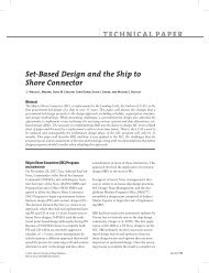
ABSTRACT<br />
Richard A. Dumas and Anthony Montano<br />
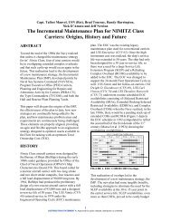
<strong>ZUMWALT</strong> <strong>Class</strong> <strong>Destroyer</strong> <strong>Systems</strong> <strong>Engineering</strong><br />
<strong>Foundations</strong> <strong>for</strong> <strong>CG</strong>(X)<br />
As the prime Mission <strong>Systems</strong> Integrator <strong>for</strong> the<br />
Navy's next generation destroyer, the Zumwalt<br />
<strong>Class</strong> <strong>Destroyer</strong>, Raytheon is responsible <strong>for</strong><br />
development and delivery of the ship’s mision<br />
system design. This includes the Mission<br />
System Equipment (such as Dual Band Radar,<br />
MK 57 Vertical Launcher System), Software<br />
(over 20M lines of delivered source code),<br />
Mission System Per<strong>for</strong>mance, and Life Cycle<br />
Sustainment. The program introduces new<br />
technologies into the Fleet to provide the Navy<br />
with a ship that fulfills requirements well into<br />
the 21 st century. The sheer size of the ef<strong>for</strong>t is<br />
also complicated by having numerous<br />
geographically and organizationally diverse<br />
companies involved in the development ef<strong>for</strong>t.<br />
In an environment of fiscal scrutiny, cost and<br />
schedule per<strong>for</strong>mance are the keys to<br />
maintaining program viability.<br />
<strong>CG</strong>(X) will face similar large-scale system-of<br />
systems integration challenges, not to mention<br />
fiscal challenges, which can benefit from the<br />
approach used by the Zumwalt team. <strong>CG</strong>(X) can<br />
benefit from a number of Total Ship <strong>Systems</strong><br />
<strong>Engineering</strong> initiatives and processes to ensure<br />
its success as well.<br />
The Zumwalt <strong>Class</strong> <strong>Destroyer</strong>'s mission is to<br />
dominate the littoral, multi-threat battlespace in<br />
all warfare areas, operating seamlessly as an<br />
integral member of the Expeditionary Strike<br />
Force, predominantly the Sea Base. The<br />
primary offensive mission <strong>for</strong> Zumwalt is to<br />
provide deep strike, precision and volume fires<br />
in support of distributed Joint and coalition<br />
<strong>for</strong>ces ashore. In addition, the Zumwalt <strong>Class</strong><br />
provides its own Air Defense (AD), Surface<br />
Warfare (SUW) and Undersea Warfare (USW)<br />
self-defense, and can effectively provide some<br />
local area protection to the Group or Force.<br />
Within each of these primary mission areas, as<br />
well as other missions such as In<strong>for</strong>mation<br />
Operations (IO), the Total Ship <strong>Systems</strong><br />
<strong>Engineering</strong> (TSSE) team develops a collection<br />
of "Mission Threads" (use case descriptions) to<br />
demonstrate an end-to-end view of each of the<br />
ship’s misions. This mission thread<br />
methodology was introduced <strong>for</strong> Zumwalt <strong>Class</strong><br />
to provide an integrated view across the Flight 1<br />
design and served to assess completeness of<br />
requirements by providing operational context<br />
<strong>for</strong> evaluating the total system. The mission<br />
thread development allows a process of<br />
“discovery” of derived capabilities to fulfill the<br />
overall mission <strong>for</strong> a ship and sailor perspective.<br />
The threads tied together CONOPS,<br />
Architecture, Manning, and Requirements and<br />
were the springboard to the larger Integrated<br />
<strong>Engineering</strong> Model (IEM) used across the<br />
geographically distributed team to provide a<br />
common development environment. This is<br />
critical to providing the Navy with a common<br />
model and language to describe the ship’s<br />
missions. All TSSE contributors (across the<br />
National team) develop their artifacts in a<br />
common model. Expanding on the groundwork<br />
laid by Zumwalt to include new missions such as<br />
Maritime Missile Defense provides a clear and<br />
proven method <strong>for</strong> <strong>CG</strong>(X) design development.<br />
This system approach will align the <strong>CG</strong>(X)<br />
teams and lead to consistency of artifacts as well<br />
as improved efficiency in the integration,<br />
management and control of products.<br />
INTRODUCTION<br />
Central to any large scale system-of-systems<br />
development is an underlying systems<br />
engineering foundation to relate the various subsystems<br />
to both the architecture and the<br />
operators. Tying this together in an operational<br />
context provides a clear vision to not only the<br />
Copyright © 2008 Raytheon Company
development teams, but also to the end-users<br />
who can view the end-to-end design within a<br />
mission context. This provides a clear<br />
advantage –it allows the end users a way to<br />
evaluate the design completeness early in the<br />
design process. The Zumwalt TSSE team<br />
developed and then matured such a foundation<br />
that is directly applicable, and more importantly<br />
re-usable, to the <strong>CG</strong>(X) design team as the next<br />
beneficiary in the "Family of Ships" strategy set<br />
<strong>for</strong>th by the Navy. The “Family of Ships”<br />
strategy allows the Navy to maximize re-use<br />
from current investments and minimize new<br />
development time and costs, and there<strong>for</strong>e<br />
minimize any disruptions while transitioning<br />
from production of Zumwalt <strong>Class</strong> <strong>Destroyer</strong>s to<br />
the <strong>CG</strong>(X). The TSSE process is a<br />
recommended contributor to support the “Family<br />
of Ships” development paradigm. The lessons<br />
learned during this maturation period are now<br />
incorporated into a team wide process resulting<br />
in a product known as the Integrated<br />
<strong>Engineering</strong> Model (IEM).<br />
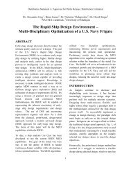
The need <strong>for</strong> an IEM was realized early in the<br />
TSSE development and was a key enabler to<br />
provide the team with a common tool to create a<br />
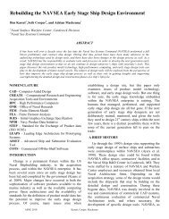
Figure 1 - The Zumwalt Mission <strong>Systems</strong> Design Process<br />
System Release Vision<br />
- Joint Doctrine, ORD, CONOPs<br />
-Drives Mission Threads and SRSs<br />
•“MSLDA ”Mission<br />
Threads<br />
•Element Level<br />
•Requirement Mapping<br />
•Algorithm<br />
Characterization<br />
DOORS<br />
Requirements<br />
Object/Activity Links<br />
DDG 1000 Rose<br />
IEM<br />
Element and<br />
Component Level<br />
Modeling<br />
In<strong>for</strong>mation Flow<br />
Traceability<br />
singular artifact that relates architecture,<br />
requirements, design and crew to each other in<br />
order to understand the allocation of functions<br />
and capabilities cross the system. The dominant<br />
factor in this challenge was showing how the<br />
Zumwalt design operates with increased<br />
automation and a significantly reduced crew size<br />
(120 ship's company vs. 348 in a DDG 51 Flight<br />
IIA destroyer). The resulting IEM Process<br />
integrated the ef<strong>for</strong>ts of a distributed team,<br />
focusing on tying the critical pieces of the<br />
design, as prioritized by the set of specified<br />
per<strong>for</strong>mance parameters in the Operational<br />
Requirements Document (ORD), into a cohesive<br />
product. This resultant product is known as<br />
Mission System Design (Figure 1) and has as its<br />
core the IEM. The IEM allows the TSSE team to<br />
decompose capabilities from a mission thread<br />
perspective to detailed software requirement<br />
specifications. The goals of a Mission System<br />
Design include:<br />
•Use a mission perspective to ensure<br />
completeness and correctness of a design<br />
that articulates what the system needs to<br />
provide to support the naval warfighter<br />
Integrated Task<br />
Repository<br />
•Sequence Diagrams<br />
•Components/Ensembles<br />
as Lifelines<br />
ADDs<br />
WSM<br />
Watchstander<br />
Model<br />
Watchstander Loading<br />
Preliminary Screen Design<br />
DDG 1000 RoseRT<br />
•Ensemble State<br />
Machines<br />
•Algorithms<br />
Per<strong>for</strong>mance<br />
Assessments<br />
SRSs
•Establish the completeness of requirements<br />
and interfaces while driving sub-system<br />
product team designs consistent with the<br />
overall Mission System Design<br />
•Define all operational manning crew tasks<br />
consistent with mission objectives<br />
• Identify common capabilities and services<br />
across mission areas, crew tasks, and subsystems<br />
• Provide a Flight 1 vision <strong>for</strong> spiral software<br />
development process<br />
Zumwalt's TSSE team took the challenge of<br />
reduced manning head on by including the crew<br />
in the IEM. Thousands of tasks were identified<br />
<strong>for</strong> crewmembers in the mission thread activity<br />
diagrams, and each of the identified tasks<br />
underwent a “task analysis” whereby numerous<br />
attributes of each and every task were identified.<br />
Results of the task analysis were documented in<br />
the Human System Integration (HSI) Task<br />
Repository, and includes in<strong>for</strong>mation such as<br />
which crewmember per<strong>for</strong>ms the task, the<br />
knowledge, skills, abilities, and tools needed to<br />
per<strong>for</strong>m the task, task priority and criticality,<br />
task duration, attributes associated with visual,<br />
cognitive, auditory, and psychomotor workloads.<br />
This modeling within the IEM provides a means<br />
to verify crew size and workloads by<br />
watchstation. It also provides a method to<br />
define areas where automation can provide<br />
potential alleviation in workloads.<br />
Another Zumwalt <strong>Systems</strong> <strong>Engineering</strong> tool that<br />
has provided ship level analysis (Key<br />
Per<strong>for</strong>mance Parameter (KPP) and Measure of<br />
Effectiveness (MOE)) capability is the Multi-<br />
Mission Analysis Tool (MMAT). Based on the<br />
IEM artifacts, MMAT is a simulation of the<br />
Zumwalt Total Ship Computing Environment<br />
(TSCE) core applications needed to evaluate<br />
system per<strong>for</strong>mance, as well as models of the<br />
mission systems equipment such as the Dual<br />
Band Radar (DBR) and Advanced Gun System<br />
(AGS). <strong>CG</strong>(X) will also have a need <strong>for</strong> this<br />
level of simulation to support trade studies,<br />
per<strong>for</strong>mance analysis, requirements analysis,<br />
and design analysis. The modular design of the<br />
model allows <strong>for</strong> easy integration of <strong>CG</strong>(X)<br />
design, threats, and tactics.<br />
APPROACH<br />
Integrated <strong>Engineering</strong> Model<br />
Modification or re-use of the Zumwalt IEM<br />
artifacts <strong>for</strong> expanded or new <strong>CG</strong>(X) operational<br />
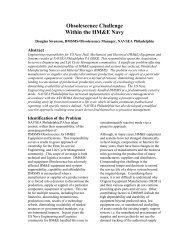
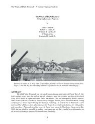
capabilities begins with the Mission Thread Use<br />
Case Descriptions. The mission thread use case<br />
descriptions (Figure 2) are developed using<br />
Universal Modeling Language (UML) activity<br />
diagrams by which functionality is allocated to<br />
system elements based on the capabilities called<br />
out to support an end-to-end mission. All<br />
"swimlanes" in the activity diagram are system<br />
elements (i.e. sub-systems within the system<br />
architecture), crew members, or external actors<br />
(i.e. actors outside the system). In Zumwalt,<br />
elements are developed within Integrated<br />
Product Teams and are comprised of both<br />
hardware and software configuration items. The<br />
diagrams depict a logical behavioral flow as well<br />
as necessary decision logic to execute a mission.<br />
The diagrams call out any necessary preconditions,<br />
as well as state and mode changes<br />
using the notes or comment feature of the UML<br />
tool. In addition to behavioral flow depictions,<br />
the diagrams contain time and other<br />
per<strong>for</strong>mance budget allocations, data flow, and<br />
watchstander task in<strong>for</strong>mation. The activity<br />
diagrams are linked to system requirements and<br />
interfaces to provide rationale and assess<br />
completeness of the design.<br />
Actor Element<br />
Activity<br />
Mission Thread Use Case Description<br />
(For System)<br />
Element<br />
Activity<br />
Element<br />
Element<br />
Activity<br />
Element<br />
Element<br />
Activity<br />
Figure 2 –Mission Thread Use Case Description<br />
The "logical behavioral flow" in these Mission<br />
Thread Use Case Description diagrams is in fact<br />
the system Concept of Operations (CONOPS)<br />
<strong>for</strong> that particular mission expressed as a UML<br />
artifact.
Expansion to <strong>CG</strong>(X) missions, such as Maritime<br />
Missile Defense (MMD), would involve<br />
extending the existing Zumwalt diagrams as<br />
shown in Figure 3. Swimlanes in the <strong>CG</strong>(X)<br />
architecture represent reuse of Non-<br />
Development Item (NDI) sub-systems including<br />
the Zumwalt Total Ship Computing<br />
Environment (TSCE) core software comprised<br />
of Command and Control, Weapons Control,<br />
Communications Control, Sensor and Vehicle<br />
Control, and <strong>Engineering</strong> Control. Re-use of<br />
Zumwalt TSCE Core also provides significant<br />
risk reduction to meeting <strong>CG</strong>(X) manning goals<br />
since the Human Computer Interface (HCI),<br />
based on the crew tasks resulting from the levels<br />
of automation delivered by TSCE software,<br />
resides within the TSCE Infrastructure. New<br />
sub-system capabilities identified in these<br />
system-level use case diagrams can then be<br />
further decomposed following the IEM process.<br />
Key external systems that would be incorporated<br />
in these diagrams would include, <strong>for</strong> example,<br />
sea based tracking systems that provide targeting<br />
data to <strong>CG</strong>(X) or other FORCEnet enablers of<br />
the warfighting capability in <strong>CG</strong>(X). The<br />
Figure 3 –Tailoring a Zumwalt IEM Artifact <strong>for</strong> <strong>CG</strong>(X)<br />
resulting work products are UML artifacts that<br />
are linked to requirements and describe the<br />
<strong>CG</strong>(X) functional baseline and new (or<br />
modified) software requirement specifications<br />
(SRS) and Architecture Description Documents<br />
(ADD) meeting the new and legacy interfaces<br />
and logically integrated into the overall system<br />
design.<br />
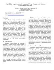
Multi-Mission Analysis<br />
As stated previously, another Zumwalt systems<br />
engineering tool <strong>for</strong> <strong>CG</strong>(X) reuse builds upon<br />
the <strong>CG</strong>(X) IEM foundation and that is the Multi-<br />
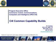
Mission Analysis Tool (MMAT). MMAT is<br />
comprised of two major simulation components<br />
–the Mission <strong>Systems</strong> Logical Design<br />
Simulation (MSLDS) and the System Effective<br />
Simulation (SES). Figure 4 shows a high level<br />
representation of MMAT.<br />
The MSLDS is based upon IEM artifacts that<br />
characterize the Total Ship Computing<br />
Environment (TSCE) system design while SES<br />
contains all the non-core system and ship<br />
models, threats, environments, geography, and<br />
simulation control. Because the core of MMAT
DD(X)-SES (FLAMES)<br />
Threats<br />
Cooperating<br />
Forces<br />
Sim Control: Time, Start/Stop/Step & Logging<br />
is developed from the Zumwalt IEM, there is a<br />
strong correlation and confidence between the<br />
model and the tactical design. The modular<br />
nature of MMAT facilitates growth <strong>for</strong> new<br />
threats encountered by <strong>CG</strong>(X), as well as<br />
incorporation of any new sub-systems needed to<br />
meet the ship's required operational capabilities.<br />
MMAT supports significant trade studies to<br />
include the sizing of the radar suite to meet the<br />
MMD mission as well as establishing the right<br />
Radar Cross Section requirements <strong>for</strong> the ship.<br />
By incorporating the full breadth "system of<br />
systems" capabilities brought to bear in<br />
completing an MMD engagement within the<br />
simulation, the <strong>CG</strong>(X) team can establish the<br />
minimum per<strong>for</strong>mance needed within <strong>CG</strong>(X)<br />
sub-systems to meet the overall MMD mission<br />
requirements.<br />
CONCLUSION<br />
Scenario<br />
Environments<br />
DD(X)<br />
Ship and<br />
Combat<br />
<strong>Systems</strong><br />
Geography / Terrain<br />
Figure 4 –Multi Mission Analysis Tool (MMAT)<br />
Seventeen years after the Navy began to develop<br />
the ship’s operational requirements<strong>for</strong> DD(X),<br />
the U.S. Navy’s Zumwalt <strong>Class</strong> <strong>Destroyer</strong> is<br />
entering production as the centerpiece of the<br />
“Family of Ships” plan and is on-track <strong>for</strong><br />
delivery to the fleet in 2013. Reuse of existing<br />
Zumwalt systems engineering products such as<br />
MMAT and the Integrated <strong>Engineering</strong> Model<br />
would provide a solid foundation <strong>for</strong> <strong>CG</strong>(X)<br />
I/F<br />
G/W<br />
MMAT<br />
Interface<br />
Gateway<br />
MSLDS (RTRose)<br />
development and should significantly shorten<br />
the time needed to define a functional and<br />
allocated baseline <strong>for</strong> <strong>CG</strong>(X). Investment in<br />
Zumwalt TSSE processes and lessons learned<br />
will be critical to <strong>CG</strong>(X) success.<br />
REFERENCES<br />
DD(X)<br />
C2, SVC,WCE<br />
& Ship Control<br />
(w/ Crew<br />
allocations)<br />
Start/Stop/Step<br />
& Logging<br />
Integrated <strong>Engineering</strong> Model (IEM) Process<br />
Work Instruction, DDG 1000 Program, June 13<br />
2006<br />
Joint Defense Capabilities Study, Final Report.<br />
Joint Defense Capabilities Study Team, January<br />
2004<br />
<strong>Systems</strong> <strong>Engineering</strong> Management Plan -<br />
Revision E, DDG 1000 Program, June 2 2006<br />
ACKNOWLEDGMENT<br />
The authors wish to thank Stuart Karon, CDR<br />
Mike Smith, USN and Daniel Gurry <strong>for</strong> their<br />
contributions in identifying source material and<br />
reviewing the draft.<br />
____________________________________<br />
Richard Dumas is the principal author and is<br />
an employee of Raytheon Company, Integrated<br />
Defense <strong>Systems</strong>. He retired from the Navy in<br />
2003 as a Commander in the <strong>Engineering</strong> Duty<br />
community after serving 21 years. His sea<br />
assignments include Auxiliaries Officer and<br />
ASW Officer in USS Harry W. Hill (DD 986),
Engineer Officer in USS Gary (FFG 51) and<br />
Engineer Officer USS Philippine Sea (<strong>CG</strong> 58).<br />
His significant shore duties include Air<br />
Dominance Officer in PMS 500 and Air<br />
Dominance Department Officer at Naval<br />
Surface Warfare Center, Pt. Hueneme Division.<br />
He obtained his bachelor's degree in physics at<br />
the University of Utah and his master's degree<br />
in physics at the U.S. Naval Postgraduate<br />
School.<br />
Anthony Montano is a Senior <strong>Systems</strong><br />
Engineer who has worked exclusively on the<br />
Zumwalt <strong>Class</strong> <strong>Destroyer</strong> Program since joining<br />
Raytheon in 2003. Anthony is currently the<br />
Sense Segment Software Requirements Lead<br />
responsible <strong>for</strong> development of the Sensor and<br />
Vehicle Control software requirements<br />
specification. His role has recently expanded to<br />
guide the Unified Modeling Language modeling<br />
ef<strong>for</strong>ts of the large and geographically diverse<br />
Zumwalt <strong>Systems</strong> <strong>Engineering</strong> Team. Anthony<br />
joined Raytheon with a bachelor's degree in<br />
Electrical and Computer <strong>Engineering</strong> from<br />
Worcester Polytechnic Institute.