the coking properties of coal at elevated pressures. - Argonne ...
the coking properties of coal at elevated pressures. - Argonne ...
the coking properties of coal at elevated pressures. - Argonne ...

You also want an ePaper? Increase the reach of your titles
YUMPU automatically turns print PDFs into web optimized ePapers that Google loves.
I<br />
/<br />
The Coking Properties <strong>of</strong> Coal <strong>at</strong> Elev<strong>at</strong>ed Pressures<br />
Michael 5. Lancet<br />
Frank A. Sim<br />
George P. Curran<br />
Conoco Coal Development Company<br />
Research Division<br />
Library, PA 15129<br />
I NTKODUCTION<br />
Conoco‘s experience with <strong>the</strong> gasific<strong>at</strong>ion <strong>of</strong> Pittsburgh No. 8 and Ohio<br />
No. 9 <strong>coal</strong>s in Westfield, Scotland has suggested th<strong>at</strong> <strong>the</strong> <strong>coking</strong> <strong>properties</strong> <strong>of</strong><br />
<strong>the</strong>se <strong>coal</strong>s, and o<strong>the</strong>r Eastern U.S. <strong>coal</strong>s by inference, under increased pressure<br />
are different from those normally measured <strong>at</strong> one <strong>at</strong>mosphere.<br />
Convinced th<strong>at</strong> <strong>the</strong> initial <strong>coal</strong>-based commercial synfuels plants in<br />
<strong>the</strong> U.S. will be gasific<strong>at</strong>ion plants, Conoco has invested in <strong>the</strong> equipment<br />
necessary to carry out this study.<br />
The work reported herein involves thc oper<strong>at</strong>ion <strong>of</strong> a pressurized coker,<br />
a pressurized Gieseler Plastometer and a device for measuring <strong>the</strong> Pressurized<br />
Swelling Index (PSI). The results <strong>of</strong> testing various <strong>coal</strong>s by <strong>the</strong>se methods are<br />
particularly useful in <strong>the</strong> evalu<strong>at</strong>ion <strong>of</strong> said <strong>coal</strong>s for use in both dry and wet<br />
bottomed Lurgi gasifiers.<br />
Seven <strong>coal</strong>s, covering a fairly wide range <strong>of</strong> ranks and characteristics,<br />
were included in this work. These included thrce Eastern U.S. bituminous<br />
<strong>coal</strong>s, EPHI-Champion and Westland from <strong>the</strong> Pittsburgh No. 8 seam and Noble County<br />
from <strong>the</strong> Ohio No. 9 seam. Also included were an Illinois No. 6 bituminous <strong>coal</strong>,<br />
Burning Star, a Western U.S. subbituminous <strong>coal</strong>, Upper Hiaw<strong>at</strong>ha, from Utah, and<br />
two bituminous <strong>coal</strong>s, Frances and Rossington from <strong>the</strong> U.K. Four <strong>of</strong> <strong>the</strong>se <strong>coal</strong>s,<br />
EPRI-Champion, Noble County, Frances and Rossington were actually run in <strong>the</strong><br />
BGC/Lurgi slagging gasifier during various programs in Westfield, Scotland.<br />
EXPERIMENTAL<br />
Drum sized samples <strong>of</strong> each <strong>coal</strong> were prepared for testing by <strong>the</strong> flow<br />
sheet shown in Figure 1. All samples were stored in sealed plastic bags until<br />
ground finer than 1/4” after which time <strong>the</strong>y were saved in a COO <strong>at</strong>mosphere in a<br />
dry ice chest.<br />
The parting m<strong>at</strong>erial or gob from each <strong>coal</strong> sample was saved and sized<br />
as needed for each test where gob addition was called for. Several <strong>of</strong> <strong>the</strong><br />
samples, as received, contained no gob, hence waste m<strong>at</strong>erial from ano<strong>the</strong>r mine<br />
in <strong>the</strong> same seam or, if th<strong>at</strong> was not available, parting m<strong>at</strong>erial from a similar<br />
<strong>coal</strong> sample was used. The following gob was used with each <strong>coal</strong> as listed<br />
below:<br />
-<br />
Coal<br />
EPRI<br />
Westland<br />
Noble County<br />
Burning Star<br />
Frances<br />
Rossington<br />
Upper Hiaw<strong>at</strong>ha,<br />
1<br />
-<br />
Gob<br />
We st land<br />
West land<br />
Egypt Valley - Ohio No. 9<br />
Hillsboro - Illinois No. 6<br />
None<br />
Hill sboro<br />
Upper Hiaw<strong>at</strong>ha
The proxitn<strong>at</strong>e and ultim<strong>at</strong>e analyses <strong>of</strong> <strong>the</strong>se Coals are given in Table 1.<br />
Also shown in this table are <strong>the</strong> he<strong>at</strong>ing values, ASTM Gieseler fluidity and Free<br />
Swelling Index (FSI), <strong>the</strong> Hardgrove grindability and a strength index for each<br />
<strong>coal</strong>. These represent <strong>the</strong> normally measured physical and chemical <strong>properties</strong> <strong>of</strong><br />
<strong>coal</strong>.<br />
The Gieseler fluidity in DDPhl and <strong>the</strong> Free Swelling Index (FSI)<br />
reported in Table 1 are <strong>the</strong> standard ASl'hl test values for each <strong>coal</strong>.<br />
The rel<strong>at</strong>ive strength <strong>of</strong> eacli <strong>coal</strong> was determined by <strong>the</strong> CCDC mini<br />
drum method which consists <strong>of</strong> tumbling 3 10 g sample in a specially designed 8"<br />
diameter tumbler with two lYOo opposed internal vanes. A composite mini drum<br />
index was calcul<strong>at</strong>ed for each <strong>coal</strong> which can be used to compare <strong>the</strong> rel<strong>at</strong>ive<br />
strengths or <strong>coal</strong>s and/or cokes. The higher <strong>the</strong> number <strong>the</strong> stronger <strong>the</strong> m<strong>at</strong>erial.<br />
The same test was used to measure <strong>the</strong> strengths <strong>of</strong> all cokes produced in <strong>the</strong><br />
pressure coker runs described l<strong>at</strong>er.<br />
The <strong>coal</strong> strengths, ranging from a low <strong>of</strong> 0.81 for <strong>the</strong> Noble County<br />
<strong>coal</strong> to 0.94 for <strong>the</strong> Frances, are quite high. In almost every case <strong>the</strong> strength<br />
<strong>of</strong> each <strong>coal</strong> is gre<strong>at</strong>er than th<strong>at</strong> <strong>of</strong> <strong>the</strong> cokes derived from <strong>the</strong>m.<br />
The grindability numbers are consistent with <strong>the</strong> strength indices with<br />
Frances <strong>at</strong> 38.6 beiJlg thc hardest to grind and <strong>the</strong> strongest from a strength indcx<br />
standpoint. Based on <strong>the</strong> grindability all Lhe <strong>coal</strong>s are physically rugged and<br />
should pose no problems upon feeding to a Lurgi gasifier.<br />
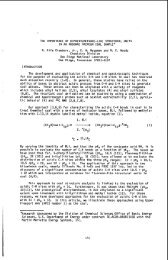
Pressurized Coal Fluidity Studies<br />
The measurcment <strong>of</strong> <strong>the</strong> fluidity or <strong>coal</strong>s as <strong>the</strong>y are he<strong>at</strong>ed through<br />
350 to 500"~ has bcen uf signiiicant benciit to <strong>the</strong> steel industry in predicting<br />
<strong>the</strong> performance <strong>of</strong> various <strong>coal</strong>s in slot ovcns. The standard method <strong>of</strong> determin-<br />
I ng <strong>coal</strong> fluidity is via <strong>the</strong> Gieseler plastomcLcr. This tesl, normally carried<br />
out <strong>at</strong> 1 <strong>at</strong>ni total pressure in air, consists <strong>of</strong> applying a constant torque to a<br />
rabble arm stirrer, packed in a sample <strong>of</strong> finely ground <strong>coal</strong>, and measuring <strong>the</strong><br />
r<strong>at</strong>e ol' rot<strong>at</strong>ion <strong>of</strong> <strong>the</strong> stirrer as <strong>the</strong> sample is he<strong>at</strong>ed <strong>at</strong> a constant r<strong>at</strong>e<br />
(usually 3°C/tnin) through <strong>the</strong> plastic zone.<br />
In general, <strong>coal</strong>s <strong>of</strong> higher rank (except anthracite) are found to be<br />
more fluid by this test than those <strong>of</strong> lower rank. Little is known, however,<br />
about <strong>the</strong> fluidity <strong>of</strong> <strong>coal</strong>s <strong>at</strong> elev<strong>at</strong>ed <strong>pressures</strong> and in gas <strong>at</strong>mospheres o<strong>the</strong>r<br />
than air. ( ' 1 ') This becomes <strong>of</strong> particular interest for moving bed <strong>coal</strong> gasifiers<br />
where raw <strong>coal</strong> is introduced <strong>at</strong> ra<strong>the</strong>r high temper<strong>at</strong>ures and <strong>at</strong> elev<strong>at</strong>ed <strong>pressures</strong><br />
<strong>of</strong> reducing gas. Hence, <strong>the</strong> work described herein was aimed <strong>at</strong> determining <strong>the</strong><br />
effect <strong>of</strong> <strong>the</strong>se varlables, as well as higher he<strong>at</strong>ing r<strong>at</strong>es, on <strong>the</strong> fluidities <strong>of</strong><br />
different <strong>coal</strong>s. Table 2 lists <strong>the</strong> parameters tested in this work.<br />
Appar<strong>at</strong>us:<br />
The basic equipment used in this work has been described previously.(')<br />
Uoth <strong>the</strong> he<strong>at</strong>ing r<strong>at</strong>e and <strong>the</strong> torque are continuously variable on this machine<br />
between <strong>the</strong> values <strong>of</strong> 0 and 6°C/minute and 0 and 720 g.cm, respectively. The<br />
variable he<strong>at</strong>ing r<strong>at</strong>e permits examin<strong>at</strong>ion 01 <strong>the</strong> effect <strong>of</strong> this parameter on<br />
<strong>coal</strong> fluidity whereas normal Gieseler oper<strong>at</strong>ion is <strong>at</strong> a fixed he<strong>at</strong>ing r<strong>at</strong>e <strong>of</strong><br />
3'C/minute. The capability <strong>of</strong> lowering <strong>the</strong> torque below <strong>the</strong> standard value <strong>of</strong><br />
100 g.cm permits measurement <strong>of</strong> fluidities far in excess <strong>of</strong> <strong>the</strong> normal 30,000<br />
DDPhl maximum.<br />
2
Procedure :<br />
Hand picked lunips <strong>of</strong> <strong>coal</strong> were ground in air Lo -35 mesh and ei<strong>the</strong>r<br />
tested inmedi<strong>at</strong>ely or stored in a C02 <strong>at</strong>mosphere in a dry-ice chest. Coal<br />
samples Of this kind are identified in this report as "clean <strong>coal</strong>". When<br />
specified by <strong>the</strong> program, "clean" <strong>coal</strong> samples were doped with gob ground to -35<br />
mesh. Frances <strong>coal</strong> was not doped due to <strong>the</strong> clean n<strong>at</strong>ure <strong>of</strong> this seam. Tar was<br />
added to <strong>the</strong> <strong>coal</strong> and gob mixture as a solution in toluene. The <strong>coal</strong>-gob-tar<br />
slurry was <strong>the</strong>n placed in a vacuum oven and <strong>the</strong> toluene was evapor<strong>at</strong>ed <strong>at</strong> about 5OOC.<br />
i\ modified ASThl D-2639-71. "Standard hlethod <strong>of</strong> Test for Plastic<br />
Properties <strong>of</strong> Coal by <strong>the</strong> Constant-Torquc Giescler Plastometer" was employed.<br />
As opposed to <strong>the</strong> ASThl standard method, thc inajority <strong>of</strong> <strong>the</strong> runs in this study<br />
were done <strong>at</strong> a he<strong>at</strong>ing r<strong>at</strong>e <strong>of</strong> G°C/minute and only one for each <strong>coal</strong> was made <strong>at</strong><br />
<strong>the</strong> standard r<strong>at</strong>c <strong>of</strong> 3VC/niinute. Also, thc standard torque <strong>of</strong> 1.40 oz-in<br />
(100 gm-cm) was used only when <strong>the</strong> ~naximum fluidity <strong>of</strong> <strong>the</strong> <strong>coal</strong> in question was<br />
within <strong>the</strong> rangc <strong>of</strong> Llie appar<strong>at</strong>us, i.e., 0-28,000 DDmI. In <strong>the</strong> cases where <strong>the</strong><br />
<strong>coal</strong> fluidity exceeded <strong>the</strong> oper<strong>at</strong>ing range <strong>of</strong> t tic instrument, "low" torques, i.e.,<br />
0.45 oz-inch (32.4 g-cm) or 0.26 oz-inch (18.7 g-end, were employed and <strong>the</strong><br />
results were corrected by factors <strong>of</strong> 3.1 or 5.4, which are <strong>the</strong> r<strong>at</strong>ios <strong>of</strong> <strong>the</strong><br />
standard torque and Lhe lower torques, (1.4/0.45 and 1.4/0.26), respectively. A<br />
considerable degree <strong>of</strong> uncertainty may be associ<strong>at</strong>ed with <strong>the</strong> numerical value <strong>of</strong><br />
<strong>the</strong> high torque/low torque correction factor. The actual r<strong>at</strong>io <strong>of</strong> <strong>the</strong> torques<br />
is <strong>the</strong>oretically correct for Newtonian fluids. llowever, since each <strong>coal</strong> in its<br />
plastic st<strong>at</strong>e limy devi<strong>at</strong>e from Newtonian behavior to a different degree, <strong>the</strong><br />
values <strong>of</strong> 3.1. or 5.4 may only be considered to be approxim<strong>at</strong>ions to <strong>the</strong> true<br />
values.<br />
When <strong>the</strong> Lest was to be performed in a gas mixture containing 18 or<br />
31.5 vol 4 H2 <strong>at</strong> a total pressure <strong>of</strong> 350 psig, <strong>the</strong> pressure vessel containing <strong>the</strong><br />
plastometer was evacu<strong>at</strong>ed and <strong>the</strong>n pressurlzed with hydrogen to 51 psig and 100<br />
~psig, respectively. The hydrogen was <strong>the</strong>n diluted to <strong>the</strong> desired degree by<br />
pressurizing <strong>the</strong> vessel up to 350 psig with prepurificd nitrogen. The remainder<br />
<strong>of</strong> <strong>the</strong> runs were carried out in a prepurified nitrogen <strong>at</strong>mosphere or in air.<br />
Results aiid Discussion:<br />
Tables 3 through (; show <strong>the</strong> cflccts OC <strong>the</strong> studied variables, i.e.,<br />
<strong>of</strong> <strong>the</strong> lienling r<strong>at</strong>e, cas composition, gob content, tar content, and nitrogen<br />
pressure, on <strong>the</strong> fluidity 01 <strong>the</strong> <strong>coal</strong>s studied. Figures 2 through 6 are<br />
grnphical represent<strong>at</strong>ions <strong>of</strong> <strong>the</strong> d<strong>at</strong>a obtained 011 <strong>the</strong> fluidities <strong>of</strong> <strong>the</strong> seven<br />
<strong>coal</strong>s iti this program.<br />
The following conclusions may be drawn from <strong>the</strong>se d<strong>at</strong>a:<br />
1. In all cases, an increase in <strong>the</strong> he<strong>at</strong>ing r<strong>at</strong>e resulted in<br />
substantially increased fluidity (Figures 2 and 3). This effect<br />
is directly comparable to and in complete agreement with th<strong>at</strong><br />
observed by Van Krevelen, et.al. (3)<br />
2. In all cases, except th<strong>at</strong> <strong>of</strong> Frances and Upper Hiaw<strong>at</strong>ha <strong>coal</strong>s, <strong>the</strong><br />
fluidity <strong>of</strong> <strong>the</strong> <strong>coal</strong> is moder<strong>at</strong>ely sensitive to hydrogen partial<br />
3
pressure <strong>at</strong> 350 psig total pressure (Figure I). The effects <strong>of</strong> all<br />
<strong>the</strong> variables - except <strong>the</strong> he<strong>at</strong>ing r<strong>at</strong>e - on <strong>the</strong> fluidity <strong>of</strong> Frances<br />
and Upper Hiaw<strong>at</strong>ha <strong>coal</strong> is so small th<strong>at</strong> <strong>the</strong>se <strong>coal</strong>s may be considered<br />
non- fluid.<br />
3. The observed effect <strong>of</strong> an increase i.n fluidity with an increase in<br />
total, or nitrogen pressure, Table 6, is consistent with work done<br />
previously on o<strong>the</strong>r <strong>coal</strong>s("2) in this pressure range.<br />
4, Increasing <strong>the</strong> gob content in all <strong>coal</strong>s reduced <strong>the</strong> fluidity in all<br />
cases. Frances <strong>coal</strong> was not subject to this type <strong>of</strong> test.<br />
5. The addition <strong>of</strong> 4 wt % <strong>of</strong> Pittsburgh No. 8 derived tar significantly<br />
increased <strong>the</strong> fluidity <strong>of</strong> all <strong>coal</strong>s except <strong>the</strong> Frances and Upper<br />
Hiaw<strong>at</strong>ha.<br />
The results <strong>of</strong> this work on <strong>the</strong> effect <strong>of</strong> both tot.al pressure and<br />
liydrogen partial pressure, qualit<strong>at</strong>ively support <strong>the</strong> conclusion <strong>of</strong> Lewellen, (I)<br />
however, <strong>the</strong> available d<strong>at</strong>a are insufficient to quantit<strong>at</strong>ively test this model.<br />
To fully test this model would require a much wider range <strong>of</strong> both <strong>pressures</strong><br />
(10-2-10t3 <strong>at</strong>m) and he<strong>at</strong>ing r<strong>at</strong>es (up to 104'C/min) than is currently possible.<br />
The qualit<strong>at</strong>ive correl<strong>at</strong>ions <strong>of</strong> <strong>the</strong> fluidity with <strong>the</strong> experimental<br />
parameters, as discussed above, suggest th<strong>at</strong> with additional d<strong>at</strong>a, especially<br />
from work on o<strong>the</strong>r <strong>coal</strong>s, a meaningful predictive correl<strong>at</strong>ion <strong>of</strong> <strong>the</strong>se d<strong>at</strong>a may<br />
eventually be possible. Initial <strong>at</strong>tempts to correl<strong>at</strong>e <strong>the</strong> observed fluidity<br />
d<strong>at</strong>a with various physical and chemical <strong>properties</strong> have been encouraging. There<br />
is strong evidence which suggests th<strong>at</strong> with d<strong>at</strong>a from several additional <strong>coal</strong>s a<br />
correl<strong>at</strong>ion <strong>of</strong> fluidity with various petrographic fe<strong>at</strong>ures may be obtained.<br />
Pressurized Swelling Index<br />
'The free swelling index, FSI, <strong>of</strong> <strong>coal</strong> as defined by <strong>the</strong> AS'I'h!(5) is<br />
ano<strong>the</strong>r valunble tool <strong>of</strong> <strong>the</strong> steel industry. 'I'Iiis Lest consists <strong>of</strong> rapidly<br />
he<strong>at</strong>ing a finely ground <strong>coal</strong> sample to about 800'C and observing <strong>the</strong> degree to<br />
which <strong>the</strong> <strong>coal</strong> cakes and swells. This test, as in <strong>the</strong> case <strong>of</strong> standard Gieseler<br />
work, is carried out <strong>at</strong> one <strong>at</strong>mosphere in air. The values for <strong>the</strong> ASTM FS1.s<br />
for each <strong>coal</strong> are given in Table 1. For <strong>the</strong> present work it was believed th<strong>at</strong> a<br />
similar test under simul<strong>at</strong>ed gasifier conditions might be <strong>of</strong> value in predicting<br />
<strong>the</strong> behavior <strong>of</strong> <strong>coal</strong>s as fed to a moving bed gasifier.<br />
While <strong>the</strong> pressurized swelling tests carried out in this work are as<br />
close to <strong>the</strong> ASThl standard method as possible, one major difference was unavoidable.<br />
Due to <strong>the</strong> use <strong>of</strong> elev<strong>at</strong>ed <strong>pressures</strong> <strong>the</strong> healing r<strong>at</strong>e <strong>of</strong> this test is not <strong>the</strong><br />
same as ch<strong>at</strong> prescribed by <strong>the</strong> ASTM standard Fur<strong>the</strong>rmore, <strong>the</strong> he<strong>at</strong>ing<br />
r<strong>at</strong>e <strong>at</strong> each test condition was slightly different due to <strong>the</strong> difference in<br />
pressure and <strong>the</strong>rmal conductivity <strong>of</strong> <strong>the</strong> gases used. The he<strong>at</strong>ing r<strong>at</strong>e was,<br />
however. <strong>the</strong> same for each <strong>coal</strong> <strong>at</strong> <strong>the</strong> same tesL condition and conclusions drawn<br />
from such comparisons should be valid. 111 general <strong>the</strong> coke buttons produced in<br />
<strong>the</strong> CCDC pressurized swelling index (PSI) test are significantly less voluminous<br />
than those <strong>of</strong> <strong>the</strong> ASTM test.
Appar<strong>at</strong>us:<br />
The equipment for this test, as shown schem<strong>at</strong>ically in Figure 7,<br />
consists <strong>of</strong> an electrically he<strong>at</strong>ed steel core enclosed in a pressure shell. A<br />
sample crucible holder assembly is <strong>at</strong>tached to a 1/4" lifting rod which passes<br />
through a packing gland <strong>at</strong> <strong>the</strong> top <strong>of</strong> <strong>the</strong> vessel. Str<strong>at</strong>egically loc<strong>at</strong>ed<br />
<strong>the</strong>rmocouples permit continuous monitoring <strong>of</strong> <strong>the</strong> core and crucible t.emper<strong>at</strong>urc.<br />
Procedure:<br />
A 1.00 gm sample <strong>of</strong> <strong>coal</strong>, ground to -60 mesh, was placed in <strong>the</strong> test<br />
crucible, covered with a lid and positioned in <strong>the</strong> holder. The vessel was <strong>the</strong>n<br />
closed, sealed and evacu<strong>at</strong>ed in order to displace air and <strong>the</strong>n flooded or<br />
pressurized with <strong>the</strong> desired gas. After <strong>the</strong> required pressure was <strong>at</strong>tained, <strong>the</strong><br />
lifting rod with <strong>the</strong> holder and <strong>the</strong> crucible was pushed down onto <strong>the</strong> core<br />
surface which had previously bccn equilibr<strong>at</strong>ed <strong>at</strong> 1500° 5OF. Temper<strong>at</strong>ures <strong>of</strong><br />
<strong>the</strong> Corc were recorded every 20 seconds beginning with <strong>the</strong> time when <strong>the</strong> crucible<br />
reached <strong>the</strong> core. The crucible was lifted after 5 minutes, <strong>the</strong> appar<strong>at</strong>us was<br />
depressurized, purged with nitrogen and <strong>the</strong> crucible was removed. The coke<br />
hutton was carefully taken from Ihe crucible and weighed. The pores in <strong>the</strong><br />
button were plugged by dipping i n molten paraffin and <strong>the</strong> volume was measured by<br />
w<strong>at</strong>er displacement. The swelling index was defined as <strong>the</strong> button volume in<br />
milliliters. For comparison purposes, <strong>the</strong> ASTM FSI pr<strong>of</strong>ile number is very nearly<br />
<strong>the</strong> button volume in ml. Each experiment was repe<strong>at</strong>ed 4 to 5 times due to <strong>the</strong><br />
variability in <strong>the</strong> hutton volume, and <strong>the</strong> value reported for each is <strong>the</strong> average<br />
<strong>of</strong> all runs. Normally <strong>the</strong> standard devi<strong>at</strong>ion <strong>of</strong> this average was less than f lo$.<br />
Temper<strong>at</strong>ure pr<strong>of</strong>iles were measured in order to ascertain th<strong>at</strong> <strong>the</strong><br />
samples were subJect to comparable he<strong>at</strong>ing r<strong>at</strong>es. The initial he<strong>at</strong>ing r<strong>at</strong>es are<br />
quite high (1000-1200°F/min) and <strong>the</strong> temper<strong>at</strong>ure stabilizes after 3 minutes. The<br />
he<strong>at</strong>ing r<strong>at</strong>e in both hydrogen and nitrogen is nearly <strong>the</strong> same.<br />
Expe r iment a 1 Re su 1 t s :<br />
Each <strong>of</strong> <strong>the</strong> seven <strong>coal</strong>s in <strong>the</strong> program was tested by this method. Tar<br />
obtained during oper<strong>at</strong>ion <strong>of</strong> <strong>the</strong> Westfield gasifier with Pittsburgh No. 8 <strong>coal</strong><br />
was used for <strong>the</strong> tar addition experiments with all tested <strong>coal</strong>s.<br />
The <strong>coal</strong>s and <strong>the</strong>ir mixtures with gob and tar were tested <strong>at</strong> <strong>the</strong><br />
conditions shown in Table 7.<br />
Table 8 shows <strong>the</strong> effects <strong>of</strong> <strong>the</strong> sample composition on <strong>the</strong> swelling <strong>of</strong><br />
different <strong>coal</strong>s <strong>at</strong> 365 psia total and 115 psia hydrogen partial pressure.<br />
Figure 8 is a graphical represent<strong>at</strong>ion <strong>of</strong> <strong>the</strong>se results.<br />
The experimental results lead to <strong>the</strong> following conclusions:<br />
1. There is little difference between <strong>the</strong> swelling <strong>properties</strong> <strong>of</strong> <strong>the</strong><br />
Noble County, Ohio NO. 9 <strong>coal</strong> and <strong>the</strong> two Pittsburgh seam <strong>coal</strong>s,<br />
EPRI-Champion and \Vestland, <strong>at</strong> <strong>the</strong> test conditions, i.e., <strong>at</strong><br />
1500' j: 5"F, 350 psig total pressure and 115 psia hydrogen partial<br />
pressure. 'This is in marlicd ContrasL to <strong>the</strong> 1 <strong>at</strong>m ASTU FSI d<strong>at</strong>a<br />
(Table 1) where <strong>the</strong> two Pittsburgh Seam <strong>coal</strong>s have FSI values <strong>of</strong> 7<br />
5
while <strong>the</strong> Ohio No. 9 has an FSI <strong>of</strong> only 4! The Burning Star-<br />
Illinois No. F coke buttons and those made <strong>of</strong> Rossington <strong>coal</strong> wcre<br />
considerably less voluminous lhan those ol <strong>the</strong> EPitI <strong>coal</strong>. Frances<br />
and Upper Hiaw<strong>at</strong>ha <strong>coal</strong>s are virtually non swelling.<br />
With <strong>the</strong> exception <strong>of</strong> <strong>the</strong> Noble County <strong>coal</strong>, thc order <strong>of</strong> tlle<br />
pressurized swelling index values is <strong>the</strong> same as th<strong>at</strong> <strong>of</strong> <strong>the</strong> AS111<br />
FSI values. Thc apparent gre<strong>at</strong>er effect 01 gasifier condi1.ions on<br />
<strong>the</strong> Ohio No. 9 <strong>coal</strong> than on <strong>the</strong> Pittshurgh No. E <strong>coal</strong>s may help<br />
explain some <strong>of</strong> <strong>the</strong> unexpected oper<strong>at</strong>ing difficulties which occurred<br />
when thc Noble County <strong>coal</strong> was fed to <strong>the</strong> I3GC/Lurgi Slagging gasifier<br />
in <strong>the</strong> DOE sponsorcd Westfield trials. The observed differcnccs in<br />
<strong>the</strong> caking and swelling <strong>of</strong> <strong>the</strong> Ohio No. 9 <strong>coal</strong> <strong>at</strong> Westfield versus<br />
those predicted by standard ASThl tests was one key factor which<br />
eventually led to <strong>the</strong> present CCDC feedstock evalu<strong>at</strong>ion program.<br />
It is interesting th<strong>at</strong> increased hydrogen pressurc and 1.oL:il<br />
pressure has a larger rel<strong>at</strong>ive effect on Lhc swelling <strong>of</strong> thc Noblc<br />
County <strong>coal</strong> than on its fluidity. The increase in <strong>the</strong> fluidity <strong>of</strong><br />
this <strong>coal</strong> is increased by gasifier conditions by about <strong>the</strong> sanic<br />
factor as are <strong>the</strong> two Pittsburgh seam <strong>coal</strong>s.<br />
2. Doping with gob significantly reduces <strong>the</strong> swclling <strong>of</strong> all <strong>the</strong> <strong>coal</strong>s<br />
tested except <strong>the</strong> inactive Uppcr Hiaw<strong>at</strong>hn <strong>coal</strong> where <strong>the</strong> gob<br />
addition had no effect. This observcd effect is essentially th<strong>at</strong><br />
expected from <strong>the</strong> dilrtcnl clfcct <strong>of</strong> <strong>the</strong> inert gob.<br />
3. The addition <strong>of</strong> tar to <strong>the</strong> bituminous <strong>coal</strong>s when <strong>the</strong>y have been<br />
doped with 10 wt $ gob, considerably increascs <strong>the</strong> volume <strong>of</strong> coke<br />
buttons made <strong>of</strong> <strong>the</strong>se <strong>coal</strong>s (Table 9). Tar addition to <strong>the</strong> Utah<br />
subbituminous <strong>coal</strong> does not have any effect, while <strong>the</strong> same tar<br />
addition to Frances <strong>coal</strong> increases its very low swelling activity<br />
by about 10%.<br />
4.<br />
The addition <strong>of</strong> even 4% tar has little effect on <strong>the</strong> Noble County<br />
<strong>coal</strong> (Table 9). This, coupled with <strong>the</strong> much larger observed effect<br />
<strong>of</strong> oper<strong>at</strong>ing <strong>at</strong> gasifier conditions discussed above, sugges1.s th<strong>at</strong><br />
<strong>the</strong> <strong>coal</strong>-derived tar content <strong>of</strong> this <strong>coal</strong> may be significantly<br />
higher than th<strong>at</strong> <strong>of</strong> thc o<strong>the</strong>r <strong>coal</strong>s. This, however, is not confirmed<br />
by <strong>the</strong> coker yield d<strong>at</strong>a to be discusscd l<strong>at</strong>er. It is possible th<strong>at</strong><br />
such differences in <strong>the</strong> yicld structure would he masked by reactions<br />
between <strong>the</strong> <strong>coal</strong>-derived tar and added hydrogen or even pyrolysisderived<br />
gases. hlorc <strong>coal</strong>-derived tar from <strong>the</strong> Noble County <strong>coal</strong><br />
Could also explain <strong>the</strong> observ<strong>at</strong>ion th3L this <strong>coal</strong> has Lhe highest<br />
AS'TM Gieseler fluidity 01' any <strong>coal</strong> testea (Table 1).<br />
The effect <strong>of</strong> hydrogen partial pressure on <strong>the</strong> swelling <strong>of</strong> <strong>the</strong><br />
tested, doped with 10% gob, is negligible. There was little<br />
difference between <strong>the</strong> buttons produced in 1005 N~ <strong>at</strong> 350 psig and<br />
those in 31.5% H2-68.5$ N, <strong>at</strong> 350 psig total pressure. The<br />
use <strong>of</strong> a gas containing 18 V O ~<br />
<strong>of</strong> <strong>the</strong> coke buttons <strong>of</strong> EPRI cool containing 10% gob. effect <strong>of</strong><br />
6<br />
% H~ also did not affect <strong>the</strong> volumes
<strong>the</strong> total pressure on <strong>the</strong> swelling <strong>properties</strong> was studied only with<br />
EPRI <strong>coal</strong> doped with 10% gob. Prepurified nitrogen was used and<br />
<strong>the</strong> results suggest <strong>the</strong>re is little or no effect <strong>of</strong> <strong>the</strong> total<br />
pressure on <strong>the</strong> swelling <strong>properties</strong> <strong>of</strong> this <strong>coal</strong>.<br />
While <strong>the</strong> effect <strong>of</strong> both hydrogcn prcssurc and total pressure on <strong>the</strong><br />
button Volume is small <strong>the</strong>y have a marked effcct on <strong>the</strong> shape <strong>of</strong> <strong>the</strong> coke<br />
buttons. Coking a highly caking Eastern U.S. <strong>coal</strong> in <strong>the</strong> pressurized FSI<br />
appar<strong>at</strong>us produces, <strong>at</strong> low pressure, a button with a smooth rounded top surface.<br />
At <strong>pressures</strong> above about 150 psig, however, one or more appendages which resemble<br />
stalagmites begin to appear on thc top surface <strong>of</strong> <strong>the</strong> button.<br />
This effect is not observed when lower rank <strong>coal</strong>s are processed in <strong>the</strong><br />
dcvice. Figure 9 shows a comparison <strong>of</strong> <strong>the</strong> cffcct <strong>of</strong> prcssure on <strong>the</strong> shape <strong>of</strong><br />
<strong>the</strong> buttons produced from a typical Pittshurgh No. 8 seam <strong>coal</strong> with those<br />
produccd from a less ncl.ive, Illinois Basin, <strong>coal</strong>.<br />
Apparently thc pressure tends to prcvent <strong>the</strong> whole top surface from<br />
rising as seems to be <strong>the</strong> case <strong>at</strong> <strong>at</strong>mospheric pressure, but internal <strong>pressures</strong><br />
are built up which are eventually releascd through <strong>the</strong> observed stalagmite<br />
growth.<br />
A s discussed earlicr, <strong>the</strong>re is encouraging evidence th<strong>at</strong> more d<strong>at</strong>a on<br />
<strong>the</strong>se <strong>properties</strong>, to be obtained by running more <strong>coal</strong>s through <strong>the</strong> program, will<br />
lead to a predictive correl<strong>at</strong>ion <strong>of</strong> <strong>the</strong> swelling <strong>properties</strong> based upon petrographic<br />
parameters.<br />
Pressurized Coker Studies<br />
Thc CCDC pressurized coker is a uscful tool for testing several<br />
parameters which are associ<strong>at</strong>ed with coke form<strong>at</strong>ion in <strong>the</strong> upper part <strong>of</strong> a Lurgi<br />
gasifier. Especially important in this respect is <strong>the</strong> friability which may be a<br />
key to successful stirrer design in future plants. This property is studied via<br />
<strong>the</strong> mini drum tumbler test described earlier. O<strong>the</strong>r <strong>coking</strong> <strong>properties</strong> which are<br />
studied are <strong>the</strong> effect <strong>of</strong> washing, i.e., thc effect <strong>of</strong> non-<strong>coal</strong> impurities, on<br />
<strong>the</strong> coke formed undcr pressure and <strong>the</strong> effcct <strong>of</strong> recycle tar addition on coke<br />
form<strong>at</strong>ion. An understanding <strong>of</strong> <strong>the</strong>se cffects will be important for gasifier and<br />
<strong>coal</strong> prcpar<strong>at</strong>ion facilities design requirements.<br />
All <strong>coal</strong>s included in this program were subjected to testing in <strong>the</strong><br />
pressurizcd coker systcm to ascertain tlic cffects <strong>of</strong> <strong>the</strong> total oper<strong>at</strong>ing pressure,<br />
<strong>the</strong> hydrogen partial prcssure, gob addition and tar addition on <strong>the</strong> coke strength<br />
and coke density. Product yields were determined for <strong>the</strong> runs made with clean<br />
<strong>coal</strong>. Also, chemical analysis <strong>of</strong> gases, tars and cokes were obtained for <strong>the</strong><br />
clean <strong>coal</strong> runs and <strong>the</strong> effects <strong>of</strong> <strong>the</strong> above mentioned independent variables on<br />
<strong>the</strong> methane, carbon monoxide and hydrogen contents <strong>of</strong> <strong>the</strong> product gas was<br />
i live 5t ig<strong>at</strong>ed.<br />
Appar<strong>at</strong>us:<br />
The pressurized coker is a 48” long, 2” diameter, double x wall pipe<br />
made <strong>of</strong> Alonized 316 SS. The coker tube is capable <strong>of</strong> being rot<strong>at</strong>ed about an<br />
axis loc<strong>at</strong>ed <strong>at</strong> <strong>the</strong> tube center as Shown in Figure 10. The outlet half <strong>of</strong> <strong>the</strong>
coker tube is electrically he<strong>at</strong>ed with G, 520 w<strong>at</strong>t, resistance he<strong>at</strong>ers. Skin<br />
and internal temper<strong>at</strong>urcs are continuously monitored and recorded on a strip<br />
chart. The, tar trap is a small w<strong>at</strong>er-cooled pressure vessel. A dip tube<br />
connected to <strong>the</strong> detachable lid reaches to <strong>the</strong> bottom <strong>of</strong> a teflon bottle tightly<br />
fitted into <strong>the</strong> tar trap body. Glass Wool, placed in <strong>the</strong> annular space between<br />
<strong>the</strong> dip tube and <strong>the</strong> bottle neck acts as a demister. An opening is provided in<br />
<strong>the</strong> tar trap lid for gas withdrawal.<br />
A pressure control valve is loc<strong>at</strong>ed downstream <strong>of</strong> <strong>the</strong> tar trap and is<br />
oper<strong>at</strong>ed by a recording pressure controller 3nd a pressure transmitter which is<br />
connected to <strong>the</strong> gas inlet piping <strong>of</strong> <strong>the</strong> coker.<br />
A dry ice temper<strong>at</strong>ure cold trap is loc<strong>at</strong>ed downstream <strong>of</strong> <strong>the</strong> pressure<br />
control valve. Gas sampling bags and gas meters are provided on <strong>the</strong> tail end <strong>of</strong><br />
<strong>the</strong> system.<br />
Procedure :<br />
A 100 gram sample <strong>of</strong> sized <strong>coal</strong> or <strong>of</strong> a <strong>coal</strong> and gob mixture is<br />
inserted inlo <strong>the</strong> cool inlet. side <strong>of</strong> <strong>the</strong> coker while <strong>the</strong> body is kept in <strong>the</strong><br />
horizontal position. When tar was to be added to <strong>the</strong> sample a solution <strong>of</strong> <strong>the</strong><br />
desired weight <strong>of</strong> tar in 5 ml <strong>of</strong> toluene was prepared. The solids were immersed<br />
in this solution, <strong>the</strong> toluene was evapor<strong>at</strong>ed in a vacuum oven <strong>at</strong> 5OoC and <strong>the</strong><br />
sample was chilled in an ice chest prior to loading into <strong>the</strong> coker.<br />
After <strong>the</strong> sample was charged into <strong>the</strong> coker, <strong>the</strong> inlet flange was<br />
<strong>at</strong>tached and <strong>the</strong> whole system purged with nitrogen <strong>at</strong> <strong>at</strong>mospheric pressure.<br />
He<strong>at</strong>-up was begun and when thc coker <strong>the</strong>rmowell temper<strong>at</strong>ure approached 1.300°F,<br />
<strong>the</strong> nitrogen purge was switched to <strong>the</strong> desired gas mixture and <strong>the</strong> gas flow r<strong>at</strong>e<br />
and oper<strong>at</strong>ing <strong>pressures</strong> were set as specified for <strong>the</strong> desired run.<br />
When <strong>the</strong> coker bed temper<strong>at</strong>ure reached 1472'F (800°C) an inlet gas<br />
sample was taken by opening and closing previously evacu<strong>at</strong>ed gas sample bomb. A<br />
split stream <strong>of</strong> <strong>the</strong> <strong>of</strong>f gas was diverted into a gas sample bag and <strong>the</strong> coker<br />
body was tilted into <strong>the</strong> vertical position. The sample dropped into <strong>the</strong> hot<br />
zone <strong>of</strong> <strong>the</strong> coker and <strong>the</strong> <strong>coking</strong> process was begun. This shock he<strong>at</strong>ing under<br />
pressurc <strong>at</strong>tempts to simul<strong>at</strong>e <strong>coal</strong> falling into <strong>the</strong> top <strong>of</strong> a moving bed gasifier.<br />
The power was turned <strong>of</strong>f after 15 minutes running time and <strong>the</strong> <strong>of</strong>f gas<br />
sample was collected for a total <strong>of</strong> one hour. The system was <strong>the</strong>n depressurized,<br />
<strong>the</strong> cold trap closed, and <strong>the</strong> coker was vented and kept under a small nitrogen<br />
purge until <strong>the</strong> appar<strong>at</strong>us cooled down. The tar trap was <strong>the</strong>n disconnected and<br />
<strong>the</strong> tar removed, separ<strong>at</strong>ed from <strong>the</strong> w<strong>at</strong>er phase and weighed. The coke was<br />
removed and weighed after <strong>the</strong> coker internal temper<strong>at</strong>ure had dropped below 200'F.<br />
Results and Discussion:<br />
A total <strong>of</strong> ten different tests were devised to investig<strong>at</strong>e <strong>the</strong> effects<br />
<strong>of</strong> <strong>the</strong> total oper<strong>at</strong>ing pressure, <strong>the</strong> hydrogen partial pressure and <strong>of</strong> <strong>the</strong> sample<br />
composition on coke strength, coke density, <strong>coking</strong> yields and on <strong>the</strong> composition<br />
<strong>of</strong> <strong>the</strong> products. Table 9 is a list <strong>of</strong> test conditions. All <strong>the</strong> tests were made<br />
on <strong>coal</strong> sized 314" x 114" except test 10. Experiments were performed in<br />
<strong>at</strong>mospheres <strong>of</strong> ei<strong>the</strong>r 100qb prepurified nitrogen or mixtures <strong>of</strong> prepurified<br />
nitrogen with hydrogen. It should be mentioned th<strong>at</strong> <strong>the</strong> tests identified as<br />
No. 2 and No. 7 were done for EFRI-Champion <strong>coal</strong> only.<br />
1
A comparison <strong>of</strong> <strong>the</strong> results obtained from tests Nos. 3, 4 and 5 shows<br />
<strong>the</strong> effect <strong>of</strong> total pressure, namely, <strong>at</strong>mospheric, 215 psig and 365 psig on coke<br />
strength and mercury density <strong>of</strong> <strong>the</strong> coke. Similarly, a comparison <strong>of</strong> tests<br />
Nos. 2, 3 and 6 shows <strong>the</strong> effects <strong>of</strong> 0, 65 and 115 psia hydrogen partial pressure<br />
(<strong>the</strong> balance being nitrogen) on <strong>the</strong> same variables. Tests Nos. 1, 6 and 9<br />
compare <strong>the</strong>'effects <strong>of</strong> gob addition to <strong>the</strong> <strong>coal</strong>, with test No. 1 investig<strong>at</strong>ing<br />
"clean" <strong>coal</strong>, No. 6, <strong>coal</strong> doped with 10% gob and No. 9, <strong>coal</strong> doped with 20%<br />
gob. Tests Nos. 7 and 8 study <strong>the</strong> effect on <strong>the</strong> above mentioned <strong>properties</strong> <strong>of</strong><br />
adding 5 and 10 wt $ tar to a <strong>coal</strong> sample doped with 10% gob. Test No. 10 was<br />
run on a "clean <strong>coal</strong>" sample sized 1/4" x 12 mesh <strong>at</strong> 365 psia total pressure and<br />
115 psia <strong>of</strong> hydrogen partial pressure. The finer size <strong>of</strong> <strong>the</strong> feed <strong>coal</strong> for this<br />
test allowed for :i more homogeneous sample than was possible when 3/4" x 1/4"<br />
<strong>coal</strong> Was used which, in turn, permitted better d<strong>at</strong>a on yield and coke composition<br />
to be obtained.<br />
The inherent variability <strong>of</strong> <strong>the</strong> <strong>coal</strong> and particularly th<strong>at</strong> <strong>of</strong> <strong>the</strong> gob<br />
samples used rendered any yield calcul<strong>at</strong>ions based on <strong>the</strong>se feed mixtures useless.<br />
Hence, only those runs made with undoped clean <strong>coal</strong> wcre used for yield<br />
de t e r mi na t ions .<br />
Figure 11 is a plot <strong>of</strong> <strong>the</strong> effect <strong>of</strong> various parameters on <strong>the</strong> coke<br />
strength. The plotted d<strong>at</strong>a are averages <strong>of</strong> all runs made <strong>at</strong> each set <strong>of</strong><br />
conditions. Thc following conclusions may be drawn from this figure:<br />
1. The strength <strong>of</strong> <strong>the</strong> coke made from <strong>the</strong> low fluidity <strong>coal</strong>s (Frances<br />
and Upper Hiaw<strong>at</strong>ha) and from <strong>the</strong> medlum fluidity <strong>coal</strong>s (Rossington<br />
and Burning Star) is inversely proportional to total pressure.<br />
The effect <strong>of</strong> increasing pressure on <strong>the</strong> strength <strong>of</strong> coke made<br />
from thc high fluidity <strong>coal</strong>s (EPRI, Westland and Noble County) is<br />
negligible.<br />
2. The effcct <strong>of</strong> hydrogen partial pressure on <strong>the</strong> coke strength is<br />
small and variable (Figure 11).<br />
3. The results rel<strong>at</strong>ed to <strong>the</strong> effect on <strong>the</strong> coke strength <strong>of</strong> doping<br />
clean <strong>coal</strong> with 10% and 204 gob are inconclusive. The coke strength<br />
decreases or remains basically unchanged in six <strong>of</strong> seven cases, <strong>the</strong><br />
exccption being Lhe Burning Star <strong>coal</strong>.<br />
4.<br />
The addition <strong>of</strong> 10 wt $ tar to <strong>coal</strong> previously doped with 10 wt $<br />
gob caused a slight increase in <strong>the</strong> strength <strong>of</strong> <strong>the</strong> coke produced<br />
in most cases with <strong>the</strong> exception <strong>of</strong> <strong>the</strong> Upper Hiaw<strong>at</strong>ha and Burning<br />
Star <strong>coal</strong>s,<br />
Figure 12 is a plot <strong>of</strong> <strong>the</strong> effects <strong>of</strong> pressure, gas composition and<br />
gob and tar addition on <strong>the</strong> coke density. These are particle densities as<br />
determined by mercury displacement <strong>at</strong> one <strong>at</strong>mosphere. The d<strong>at</strong>a shown in this<br />
figure suggest th<strong>at</strong>:<br />
1. The coke density remains <strong>the</strong> same or decreases very slightly when<br />
<strong>the</strong> total pressure is increased from <strong>at</strong>mospheric to 350 psig.<br />
9
2. 'The density 01' <strong>the</strong> coke produced I'roln thc studied <strong>coal</strong>s depends<br />
little on <strong>the</strong> hydrogen partial pressure. IiOWeVer, a slight increase<br />
in density with increased hydrogen pressure is seen for <strong>the</strong> high<br />
fluidity <strong>coal</strong>s.<br />
3. As cx1,ected increased gob contents lead to increased particle<br />
densi ties.<br />
4.<br />
The <strong>at</strong>idition <strong>of</strong> 10 WC % tar to low fluidity <strong>coal</strong>s did not have<br />
any effect on <strong>the</strong> density <strong>of</strong> Lhe c.oke. IloWeVCr, <strong>the</strong> Same addition<br />
to medium fluidity <strong>coal</strong>s doped with 10% gob caused <strong>the</strong> coke density<br />
to increase significant,ly. A slight increase is observed for two<br />
<strong>of</strong> <strong>the</strong> three high fluidity <strong>coal</strong>s (EPI11 and Westland) while a decrease<br />
was found for <strong>the</strong> Noblc County <strong>coal</strong>.<br />
Interestingly, his ra<strong>the</strong>r complex picture <strong>of</strong> coke strength and density<br />
may, as appears to be <strong>the</strong> case for <strong>the</strong> fluidity and swclling d<strong>at</strong>a, be<br />
explainable in terms <strong>of</strong> a few petrographic parameters. More d<strong>at</strong>a on different<br />
<strong>coal</strong>s will show just how good a correl<strong>at</strong>ion can be obtained.<br />
Yield d<strong>at</strong>a were collected for cach 01 <strong>the</strong> over 100 coker runs in this<br />
program, llowever, as mentioned earlier thc majority 01 <strong>the</strong>se d<strong>at</strong>a arc <strong>of</strong> little<br />
value. Only <strong>the</strong> d<strong>at</strong>a obtained with clean <strong>coal</strong> samples give useful yield d<strong>at</strong>a.<br />
A summary <strong>of</strong> <strong>the</strong> yield d<strong>at</strong>a lrom <strong>the</strong> runs made <strong>at</strong> simul<strong>at</strong>ed gasifier conditions<br />
(i.e., 365 psia total pressure and 115 psia hydrogen pressure) on 1/4" x 12 mesh<br />
<strong>coal</strong> is g~ven in Table 10. These d<strong>at</strong>a arc based on <strong>the</strong> average measured coke,<br />
tal- and liquid yields for all runs <strong>at</strong> thcse COIldi~ionS for each <strong>coal</strong> (On a<br />
moisture and ash free basis), with <strong>the</strong> gas yield calcul<strong>at</strong>ed by difference.<br />
In all eases <strong>the</strong> coke yield <strong>at</strong> simul<strong>at</strong>ed gasifier c.onditions <strong>of</strong> 365<br />
psia total pressure and 115 psia hydrogen partial pressure is gre<strong>at</strong>er than <strong>the</strong><br />
fixed carbon content determined for each <strong>coal</strong> <strong>at</strong> 1 <strong>at</strong>m (Table 1). This is not<br />
surprising since <strong>at</strong> elev<strong>at</strong>ed pressure <strong>the</strong> release <strong>of</strong> vol<strong>at</strong>ile components is<br />
retarded. ( 1 3 2 9 3 ) The slowing <strong>of</strong> vol<strong>at</strong>ile release allows more <strong>of</strong> this m<strong>at</strong>erial<br />
to be converted 1.0 colic <strong>at</strong> <strong>the</strong> expense <strong>of</strong> liquid and/or gas yield.<br />
The yield d<strong>at</strong>a lor Frances <strong>coal</strong>, 'Table 11, where only clean <strong>coal</strong> was<br />
used, shows th<strong>at</strong> both coke and gas yields are increased <strong>at</strong> <strong>the</strong> expense <strong>of</strong> <strong>the</strong><br />
liquid yield in going from 1 <strong>at</strong>m N2 pressure to 365 psia <strong>of</strong> NZ. Here <strong>the</strong> coke<br />
yield increases from - GS$ to - 67.5% and <strong>the</strong> gas yield increases from - 25% to<br />
29yo while <strong>the</strong> liquid yield decreases from - 10% to - 4%. Possibly liquid<br />
evolution repression can account for both <strong>the</strong> increased coke <strong>at</strong>id gas yields. If<br />
<strong>the</strong> liquid is held in <strong>the</strong> <strong>coal</strong> m<strong>at</strong>rix some <strong>of</strong> it is coked and some is fur<strong>the</strong>r<br />
converted to gas by <strong>the</strong> longer residence time <strong>at</strong> elev<strong>at</strong>ed temper<strong>at</strong>ures thus<br />
rcdtrcing thc overnll liquid yicld and increasing 1.hc cokc and gas yields. A1<br />
elev<strong>at</strong>ed hydrogen <strong>pressures</strong> (115 psia and 365 psia total pressure) <strong>the</strong> coke<br />
yield is about <strong>the</strong> same as when 365 psia <strong>of</strong> nitrogen is used, however, <strong>the</strong><br />
liquid yield is gre<strong>at</strong>ly enhanced <strong>at</strong> <strong>the</strong> expense <strong>of</strong> <strong>the</strong> gas yield. Undoubtedly<br />
react.ion between <strong>the</strong> added hydrogen and <strong>the</strong> <strong>coal</strong> are responsible for <strong>the</strong> higher<br />
liquid yield.<br />
Figure 13 shows a comparison <strong>of</strong> produced gas composition with respect<br />
to CH4, co and & <strong>at</strong> various conditions. Since most <strong>of</strong> <strong>the</strong>se d<strong>at</strong>a were obtained<br />
with <strong>coal</strong> doped with gob <strong>the</strong> results may not bc as 1.eliable as if only clean <strong>coal</strong><br />
10
was used, however, general trends are not expected to differ from those observed<br />
here. The methane content <strong>of</strong> <strong>the</strong> product gas is SO-lOO% higher than for <strong>the</strong><br />
case with no added hydrogen while <strong>the</strong> hydrogen content <strong>of</strong> <strong>the</strong> product is<br />
considerably lower.<br />
Qualit<strong>at</strong>ively this suggests th<strong>at</strong> hydrogen evolved irom <strong>the</strong> <strong>coal</strong> escapes<br />
before it has time to react fur<strong>the</strong>r wit.h 1.hc remaining <strong>coal</strong> m<strong>at</strong>rix. The CO<br />
content <strong>of</strong> <strong>the</strong> product appears virtually unaCf‘ected by pressure and <strong>the</strong> addition<br />
01 gob and/or tar has little or no cffect 011 <strong>the</strong> gas composition.<br />
CONCLUSIONS<br />
Thc experimental d<strong>at</strong>a presented herein should provide a start 011 <strong>the</strong><br />
required d<strong>at</strong>a base which will ultim<strong>at</strong>ely permit <strong>the</strong> prediction <strong>of</strong> <strong>the</strong> <strong>coking</strong><br />
<strong>properties</strong> <strong>of</strong> <strong>coal</strong>s being considered as potential gasifier feedstocks. The<br />
limited d<strong>at</strong>a obtained pertaining to pyrolysis yields and gas composition are<br />
encouraging and suggest h<strong>at</strong> accur<strong>at</strong>e gas yield predictions may also he possible<br />
<strong>at</strong> <strong>the</strong> conclusion <strong>of</strong> his program. The cffccts or process variables on <strong>coal</strong><br />
swelling and fluidity has been fairly well established, but more work is needed<br />
to get predictive ma<strong>the</strong>m<strong>at</strong>ical correl<strong>at</strong>ions <strong>of</strong> <strong>the</strong>se as well as <strong>coking</strong> and<br />
pyrolysis <strong>properties</strong> or Coals.<br />
Acknowledgement<br />
This work was supported in part by <strong>the</strong> Electric Power ‘Research Institute<br />
(EPRI). Contract. ?io. 1tP 1267-7.<br />
REFERENCES<br />
1. Kaiho, M. and ‘l’oda, Y., Changes in Thermoplastic Properties <strong>of</strong> Coal<br />
Under Pressure 01 Various Gases. Fuel 5X, 397 (hlay, 1979).<br />
-<br />
2. Lancet, !VI. S. and Sim, F. A., The ECfect <strong>of</strong> Pressure and Gas Composition<br />
on <strong>the</strong> Fluidity <strong>of</strong> Pittsburgh No. 8 Coal, Preprints <strong>of</strong> Fuel Chemistry<br />
Div. ACS, Vol 26, No. 3 (August, 1981).<br />
-<br />
3. Van Krevelen. U. W., Ilitntjcns, F. S. and Dormans, H. N. hl., Chemical<br />
SLructurcs and Propcrties <strong>of</strong> Coal XVI - - Plastic Behavior on He<strong>at</strong>ing,<br />
Fuel 35, 462 (1955).<br />
-<br />
4. Lewellen, P. C., Product Decomposition Effects in Coal Pyrolysis, hlasters<br />
Thesis, Department <strong>of</strong> Chemical Engineering, MIT, (1975).<br />
5. ASTN Standard hlethod D720-67, Free Swelling Index <strong>of</strong> Coal (1977).<br />
11
- Coal<br />
0 ri 6 i 1<br />
hloisture<br />
As Atinlyzed<br />
Proxim<strong>at</strong>e, Dry<br />
\'olarilc hl:il.ter, Q<br />
Fixed Carbon<br />
A SI1<br />
Ultim<strong>at</strong>e, Dry<br />
Hydrogen,<br />
c 3 1.b011<br />
S 1 L rogen<br />
Oxygen (Diff.)<br />
Sulfur<br />
Ash<br />
HIN, Dry<br />
Btu/lb<br />
Ultim<strong>at</strong>e, hV\F<br />
Hydrogen, $<br />
C a rlmn<br />
Nitrogen<br />
Oxygen (Diff.)<br />
Sulfur<br />
Gie scler Flu id i t y ,<br />
(DD Phl)<br />
Free Swelling<br />
Index (FSI)<br />
Hard grove<br />
Grindability<br />
S t rengt h Index<br />
I'g 11.<br />
No. 8<br />
Scaiii<br />
Table 1<br />
Coniposition <strong>of</strong> Fccd Coals<br />
2. 23<br />
37.93<br />
.I 9. 9.1<br />
12.13<br />
.I. 93<br />
72.52<br />
1. .I5<br />
li.80<br />
2.17<br />
12.13<br />
12,955<br />
5.til<br />
b2.53<br />
1.6s<br />
7.74<br />
2.47<br />
5,100<br />
7<br />
52.9<br />
0.849<br />
I'g 11 .<br />
No. 8<br />
Scam<br />
2.02<br />
3G.28<br />
52.21<br />
11.51<br />
4.84<br />
73.13<br />
1.51<br />
7.16<br />
1.65<br />
11.51<br />
12,99C<br />
5:17<br />
82.64<br />
1.71<br />
8.09<br />
2.09<br />
15,300<br />
7<br />
62.9<br />
0.886<br />
12<br />
U<br />
Ohio<br />
No. 3<br />
ScJm<br />
2.tix<br />
.1-I . 3(i<br />
46.10<br />
9.54<br />
5.lG<br />
72.70<br />
1.05<br />
8.12<br />
3.43<br />
9.54<br />
13,370<br />
5.70<br />
80.37<br />
l.lG<br />
n. 98<br />
3.79<br />
27,000<br />
4<br />
49.7<br />
0.806<br />
Ill.<br />
No. G<br />
Scnm<br />
9.99<br />
42.94<br />
43.52<br />
13.5.1<br />
'I . 6.2<br />
(;3.00<br />
1 . 31<br />
$).?ti<br />
3.21<br />
13.5.1<br />
12,165<br />
5.3x<br />
78.65<br />
1.52<br />
10.71<br />
3.75<br />
4 . 7<br />
3.5<br />
.?X. 7<br />
0.831<br />
Scotlnnd England Utah<br />
6. 62<br />
38.84<br />
56.93<br />
4.23<br />
5.07<br />
78.73<br />
1. 60<br />
9.93<br />
0.44<br />
4.23<br />
13,790<br />
5.29<br />
82.21<br />
1.67<br />
10.37<br />
0.46<br />
1 .o<br />
1.5<br />
38. 6<br />
0.942<br />
5.81<br />
38.01<br />
59.04<br />
2.95<br />
5 .06<br />
79.13<br />
1.66<br />
9. G 8<br />
1.52<br />
2.95<br />
1'1,195<br />
5.21<br />
81.54<br />
1.71<br />
9.97<br />
1.57<br />
5.3<br />
3.5<br />
48.3<br />
0.847<br />
7.39<br />
41.74<br />
50.36<br />
7.90<br />
4. 9'1<br />
72.08<br />
1.25<br />
13.35<br />
0.48<br />
7.90<br />
12,688<br />
5.36<br />
78.26<br />
1.36<br />
14.50<br />
0.52<br />
0<br />
1<br />
45. 6<br />
0.884
1<br />
D<br />
13<br />
3<br />
G
14<br />
7<br />
..<br />
..<br />
11
Table 8<br />
L_<br />
Effect os FaeO Compo.lrl""<br />
on <strong>the</strong> Swelling 01 Diflercni Coals<br />
Zl'lll<br />
coa 1<br />
/I" rn, "E<br />
Cha.-;rior. hcsilznd Soblc Stor upper<br />
PII~SCYIE~ Pittsburgh<br />
so. n So. 6<br />
CounTy<br />
Ohio Xo. 9<br />
Illinois<br />
So. 6<br />
FrnnCe~<br />
Sc<strong>of</strong>iniid<br />
RO55ingIDn<br />
EnClsnrl<br />
H1aYalha<br />
Utah<br />
-------<br />
3.0<br />
a,.:<br />
2.2<br />
2.6<br />
2.8<br />
1.9<br />
a.1<br />
__<br />
3.0<br />
2.3<br />
2.1<br />
-.<br />
2.0<br />
1.8<br />
1.6<br />
--<br />
1.0<br />
.-<br />
_ _<br />
__<br />
1.8<br />
1.8<br />
1.7<br />
._<br />
0.9<br />
0.9<br />
0.9<br />
-_<br />
2.9 3.8 2.3 1.9 1.1 2.0 0.9<br />
16
I<br />
0<br />
0<br />
0<br />
17<br />
2.1. A<br />
22.0<br />
..<br />
I "<br />
2-.7<br />
20.8<br />
21.8<br />
25.2<br />
..<br />
..
i-l SPARE SAblPLE<br />
Plortlc 209<br />
Figure I<br />
Sample Prepar<strong>at</strong>ion Scheme<br />
LATER USE<br />
114 Sample Plastic Bag<br />
RIFFLE<br />
I PROGRklA TESTS I k Sample '14 Sample<br />
'12 Sample<br />
I--<br />
>-<br />
c<br />
0<br />
3<br />
ti. 3<br />
TO ANliLYTlCAL LAB TO PETROGRAPHY LAB SAVE<br />
200,00(<br />
100,00(<br />
50.00(<br />
10,000<br />
5POO<br />
Figure 2<br />
EFFECT OF HEATING RATE CN THE FLUIDITY OF<br />
PITTSBURGH NO 8 ANU OHIO NO 9 SEA:.! COALS<br />
/+<br />
/<br />
TOTL F2ESSU;E<br />
365 PSlP<br />
HYC8OGEW PRESSEE:<br />
115 ?SIB<br />
+ E?i?I.C2X!?IC>I<br />
o WESTLCi3<br />
/ O NOELE CO<br />
3 G<br />
HEATING RATE ('C/:.ll:Il<br />
18
100,000 -<br />
50,000 -<br />
- 10,000 -<br />
b<br />
- a<br />
D 5,000 .<br />
r<br />
c_<br />
e<br />
3<br />
J u_<br />
Figure 3<br />
EFFECT OF HEATING RATE ONTHE FLUIDITY OF<br />
BURNING STAR AND ROSSINGTON COALS<br />
lDOO<br />
100 -<br />
50 -<br />
I I I<br />
3 6<br />
HEATING RATE I"CIMIN.1<br />
--o<br />
.+-<br />
--c -,----o--<br />
/e-.-<br />
+-t-<br />
/A'<br />
18VOL.% H2 31 5 VOL.% H1<br />
100%N2 ~~VOL.~I~NI 685VOL%N?<br />
0-<br />
0-<br />
IOTbl PRESSURE:<br />
365 KIA<br />
HYDROGEN PRESSURE<br />
115 PSlP<br />
a BURNING STAROAL<br />
0 ROSSINGTON COAL<br />
Figure 4<br />
EFFECT OF GAS COMPOSITION ON THE FLUIDITY OF<br />
VARIOUS COALS<br />
TOTAL PRESSURE 350 B IG<br />
HEATING RATE. 67C MIN<br />
SAMPLE: 9OWT %-35Y COAL+1OWTS-lOOHG00<br />
+ EPRI-CHAYPION<br />
OWESTLANO<br />
o NOBLE co<br />
0 ROSSINGTON<br />
A BURNING STAR<br />
.NOTE'<br />
SCALE CHANGE<br />
a'<br />
I<br />
19
-<br />
z<br />
c<br />
100,000<br />
50,000<br />
10,000<br />
0<br />
n 5,000<br />
I<br />
y<br />
Y<br />
e<br />
1,000<br />
500<br />
100,000 -<br />
Figure 5<br />
EFFECT OF GOB ADOITION ON THE FLUIDITY OF<br />
VARICUS COALS<br />
TOTAL PRESSURE: 365 PSlP<br />
HYDROGEN PRESSURE: 115 PSlA<br />
HEATING RATE: 6'Cl YIN<br />
-<br />
O\<br />
: t.<br />
-<br />
-=-<br />
-<br />
-<br />
-<br />
-<br />
50,000 - +-<br />
e .<br />
a-<br />
1m:o<br />
COAL: Goa RATIO<br />
B 0'<br />
2 10,000 -<br />
-<br />
* 5,000 -<br />
n<br />
3<br />
Y<br />
1,000 -<br />
500 -<br />
9O:K):O<br />
0 /<br />
t EPRI-CWYWN<br />
0 WESTLAND<br />
0 NOBLE CO.<br />
Figure 6<br />
EFFECT OF TAR ADDITION ON THE FLUIDITY OF<br />
VARIOUS COALS DOPE0 WITH 10% GOB<br />
__-. ,-<br />
t'<br />
/$<br />
09:10:1<br />
COAL: GOB: TAR RATIO<br />
RESINGTON<br />
A B UllNG STAR<br />
TOTAL PRESSURE : 365 PSlA<br />
HYDROGEN PRESSURE: 115 PSU<br />
HEATING RATE: 6'WMlN<br />
t EPRI-CWUPION<br />
0 WESTLAND<br />
0 NOBLE CO<br />
0 ROSSINGTON<br />
A BURNING STAR<br />
I<br />
1
4 0<br />
Figure 7<br />
Pressurized Swelling Index Appar<strong>at</strong>us'<br />
Figure 8<br />
EFFECT OF SAMPLE COMPOSITION ON THE SWELLING<br />
OF VARIOUS COALS<br />
3 0-<br />
2.0 -.<br />
LOT<br />
TI0<br />
t EPRI-CHAYPION<br />
0 WESTLANO<br />
0 NOBLE CO.<br />
BURNING STLR<br />
* FRANCES<br />
ROSSINGTON<br />
A UPPER HIPWATHA<br />
T= 1500t 5.F<br />
Plot = 365 Pilo<br />
PHI : 115 Ria
Flnure 9<br />
SWELLltlG PROPERTIES OF PITTSBURGH NO. 8 8 ILLllOlS NO, t COPLS<br />
PITTSBURGH No. 8<br />
7<br />
+ 1<br />
1 ATMOSPHERE - NITROGEN 1 ATMOSPHERE - NITROGEN<br />
1 350<br />
PSIG - NITROGEN<br />
L<br />
350 PSIG - HYDWGEN<br />
ILLINOIS No. 6<br />
BURNING STAR<br />
I<br />
350 PSIG - NITROGEN 1<br />
I<br />
3% PSIG - -1<br />
Figure IO<br />
Pressurized Coker<br />
22<br />
HYDROGEN
Figure 11<br />
EFFECT OF SAMPLE COMPOSITION, TOTAL PRESSURE AND<br />
HYDROGEN PRESSURE ON THE COKE STRENGTH<br />
T : BOO*C<br />
Plol 365 Psi0<br />
PHz. 115 Psi0<br />
11055-<br />
TOTAL<br />
PRESSURE<br />
(PrlOi<br />
T EOO'C<br />
Fi ure 12<br />
EFFECT OF SAMPLE CdMPOSITION, TOTAL PRESSURE AND<br />
HYDROGEN PRESSURE ON COKE DENSITY<br />
I SAHRE COHWSITION<br />
23<br />
101.365 Prii<br />
-1Cd:Gob<br />
+%/ 3-t-<br />
t EPRI-CHAMPION<br />
DWESnANO<br />
ONOBLE CO.<br />
AByRNlNG STAR<br />
+FRANCES<br />
oROSSlNGTON<br />
.UPPER HIAW&THA<br />
VALUES SHOWN ARE<br />
AVERAGES OF ALL<br />
DATA AT<br />
GIVEN CONOITIONS<br />
-1.<br />
VALUES SHOWN<br />
.---*<br />
___<br />
' I 65 I<br />
HYDROGEN<br />
PRESSURE<br />
IPriol<br />
EPRI-CHAMPION<br />
WESTLAND<br />
'NOBE CO<br />
.BURNING STAR<br />
-FRANCES<br />
I RWSSINGTON<br />
,UPPER<br />
HI AWPTHA<br />
&?E AVEPdGB<br />
Of AU OATA AT<br />
GlMN aYlDTlONS
Fi ure 13<br />
EFFECT OF TOTAL PRESSQRE, HYDROGEN PRESSURE AND<br />
SAMPLE COMPOSITION ON Hz, CO AND CH, CONTENT IN<br />
PRODUCT GAS<br />
'tot (PSI01<br />
': 800OC<br />
'Hi0 Prio<br />
:ICool :Gob<br />
(I<br />
a<br />
PHz( Ria)<br />
T : 800' C<br />
Ptot: 365 Psi1<br />
9:ICwl:Gob<br />
.800°C, Ptol:365 Psi0<br />
PHz. 115 Psi0<br />
24<br />
tEPRI-CHAMPION<br />
OWESTLAND<br />
o NOBLE CO.<br />
A BURNING STAR<br />
* FRANCES<br />
0 AOSSINGTON<br />
A UPPER<br />
HIAWATHA<br />
VUES SHOWN<br />
ARE AVERAGES OF<br />
AU DATA AT<br />
GIVEN CONDITIONS
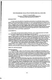
EFFECTS OF PREOXIDATION ON PYROLYSIS BEHAVIOR<br />
AND RESULTANT CHAR STRUCTURE OF CAKING COALS<br />
P D. J. Maloney and R. G. Jenkins<br />
The Fuels and Combustion Labor<strong>at</strong>ory<br />
The Pennsylvania St<strong>at</strong>e University, University Park, PA 16802<br />
INTRODUCTION<br />
l Coal gasific<strong>at</strong>ion processes may be divided into two stages. They are, <strong>the</strong><br />
initial rapid release <strong>of</strong> vol<strong>at</strong>ile m<strong>at</strong>ter and <strong>the</strong> rel<strong>at</strong>ively slow gasific<strong>at</strong>ion <strong>of</strong><br />
<strong>the</strong> residual char. These two processes are not, however, totally independent be-<br />
1, cause <strong>the</strong> he<strong>at</strong> tre<strong>at</strong>ment conditions under which <strong>coal</strong> pyrolysis occurs determine,<br />
( to a large extent, <strong>the</strong> structure and reactivity <strong>of</strong> <strong>the</strong> remaining char (1). The<br />
' importance <strong>of</strong> understanding devol<strong>at</strong>iliz<strong>at</strong>ion kinetics has long been recognized<br />
(2-6). However, it is surprising to note th<strong>at</strong> very little inform<strong>at</strong>ion is available<br />
in <strong>the</strong> liter<strong>at</strong>ure regarding <strong>the</strong> structure and reactivity <strong>of</strong> <strong>the</strong> chars produced<br />
1 in <strong>the</strong>se studies.<br />
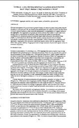
The work described here is concerned with <strong>the</strong> utiliz<strong>at</strong>ion <strong>of</strong> bituminous (caking)<br />
<strong>coal</strong>s in dilute phase, rapid he<strong>at</strong>ing gasific<strong>at</strong>ion and combustion systems. Two<br />
highly caking <strong>coal</strong>s were pyrolyzed in an entrained flow tube furnace system and<br />
devol<strong>at</strong>iliz<strong>at</strong>ion kinetics determined for each <strong>coal</strong> <strong>at</strong> temper<strong>at</strong>ures <strong>of</strong> 900 and 1000°C.<br />
Structural <strong>properties</strong> <strong>of</strong> <strong>the</strong> chars collected in this work were <strong>the</strong>n analyzed. In<br />
addition, <strong>the</strong> effects <strong>of</strong> mild preoxid<strong>at</strong>ion <strong>of</strong> <strong>the</strong>se <strong>coal</strong>s upon <strong>the</strong>ir subsequent<br />
pyrolysis behavior were examined. Samples <strong>of</strong> each <strong>coal</strong> were oxidized to various<br />
levels prior to he<strong>at</strong> tre<strong>at</strong>ment. Devol<strong>at</strong>iliz<strong>at</strong>ion kinetics and structural <strong>properties</strong><br />
<strong>of</strong> <strong>the</strong> chars produced were <strong>the</strong>n analyzed. Results reported here follow <strong>the</strong> develop-<br />
ment <strong>of</strong> char structure with varying he<strong>at</strong>, tre<strong>at</strong>ment conditions and examine changes<br />
in char morphology which occur on preoxid<strong>at</strong>ion <strong>of</strong> <strong>the</strong>se <strong>coal</strong>s. This work is <strong>of</strong><br />
practical importance in future design consider<strong>at</strong>ions for dilute phase gasifiers<br />
and <strong>of</strong> particular interest in gasific<strong>at</strong>ion schemes where agglomer<strong>at</strong>ion <strong>of</strong> caking<br />
<strong>coal</strong>s can cause serious problems.<br />
EXPERIMENTAL<br />
Pyrolysis experiments were conducted in an entrained flow tube furnace somewh<strong>at</strong><br />
similar to th<strong>at</strong> described by Scaroni et al. (7,8) and Nsakala and coworkers (9).<br />
Briefly, a dilute-phase <strong>coal</strong> stream is entrained in a primary carrier gas, passed<br />
through a w<strong>at</strong>er cooled probe and <strong>the</strong>n injected into <strong>the</strong> center <strong>of</strong> a prehe<strong>at</strong>ed secondary<br />
gas stream. The secondary gas stream enters <strong>the</strong> reaction zone <strong>at</strong> a temper<strong>at</strong>ure<br />
slightly above <strong>the</strong> furnace wall temper<strong>at</strong>ure so th<strong>at</strong> upon mixing <strong>the</strong> combined<br />
gas stream <strong>at</strong>tains <strong>the</strong> desired reaction temper<strong>at</strong>ure (? 10OC). The primary modes<br />
<strong>of</strong> <strong>coal</strong> particle he<strong>at</strong>ing are conduction from <strong>the</strong> gas and radi<strong>at</strong>ion from <strong>the</strong> furnace<br />
walls. He<strong>at</strong>ing r<strong>at</strong>es in excess <strong>of</strong> 10,OOO°C/s are estim<strong>at</strong>ed. Coal particles travel<br />
in a pencil stream down <strong>the</strong> axis <strong>of</strong> <strong>the</strong> furnace tube. Samples are collected and<br />
rapidly quenched (> 10,OOO°C/s quench r<strong>at</strong>e) using a w<strong>at</strong>er cooled probe which is<br />
inserted up <strong>the</strong> axis <strong>of</strong> <strong>the</strong> furnace. Reaction times are varied by changing <strong>the</strong><br />
position <strong>of</strong> <strong>the</strong> sampling probe rel<strong>at</strong>ive to <strong>the</strong> injector. The oper<strong>at</strong>ing conditions<br />
<strong>at</strong> each temper<strong>at</strong>ure studied are given in Table 1.<br />
Helium is used as <strong>the</strong> primary<br />
The secondary<br />
carrier gas and is adjusted to maintain isokinetic sample injection.<br />
gas is nitrogen.<br />
Weight loss due to pyrolysis was determined using ash as a tracer. The proxi-<br />
m<strong>at</strong>e analyses <strong>of</strong> <strong>the</strong> samples used in this work are presented in Table 2. The <strong>coal</strong>s<br />
examined were PSOC-1133 a LV <strong>coal</strong> from <strong>the</strong> Lower Kittaning seam in Pennsylvania<br />
25
TABLE 1. OPERATING CONDITIONS<br />
Oper<strong>at</strong>ing Temper<strong>at</strong>ure "C 900 1000<br />
Coal Feed R<strong>at</strong>e g/min 0.5 0.5<br />
Mean Gas Velocity cm/s<br />
Secondary N2/Primary He (Mole Basis)<br />
97<br />
26.4<br />
TABLE 2. PROXIMATE ANALYSES OF SAMPLES (200x270 mesh fractions)<br />
Sample Moisture, % Ash, % Vol<strong>at</strong>ile M<strong>at</strong>ter, % Fixed Carbon, %<br />
PSOC-1099 (Raw Coal) 1.6 9.0 33.7 56.7<br />
PSOC-1099 (1% O2 added) 0.9 12.6 32.5 64.0<br />
PSOC-1133 (Raw Coal) 0.4 16.4 18.5 64.7<br />
PSOC-1133 (0.5% O2 added) 1.1 19.3 17.6 62.0<br />
PSOC-1133 (1% O2 added) 1.1 19.5 18.2 62.2<br />
and PSOC-1099 a HVA <strong>coal</strong> from <strong>the</strong> Pittsburgh seam in Pennsylvania. All work was con-<br />
ducted on 200x270 mesh size fractions with mean particle diameter <strong>of</strong> 63 um.<br />
Preoxidized samples were prepared in a fluidized bed furnace. Samples <strong>of</strong> sized<br />
<strong>coal</strong> (200x270 mesh) were fluidized in nitrogen and brought to reaction temper<strong>at</strong>ure<br />
(175OC). The fluidizing gas was <strong>the</strong>n switched to air and <strong>the</strong> samples were oxidized<br />
for various predetermined times. Oxid<strong>at</strong>ion times were determined based upon <strong>the</strong>rmo-<br />
gravimetric studies <strong>of</strong> <strong>the</strong> air oxid<strong>at</strong>ion <strong>of</strong> each <strong>coal</strong>. It is assumed th<strong>at</strong> oxid<strong>at</strong>ion<br />
r<strong>at</strong>es in <strong>the</strong> <strong>the</strong>rmobalance and fluidized bed systems are equivalent. This assumption<br />
is valid if one insures th<strong>at</strong> <strong>the</strong> O2 partial pressure in each system is <strong>the</strong> same<br />
and th<strong>at</strong> <strong>the</strong>re are no bed diffusion effects in <strong>the</strong> <strong>the</strong>rmobalance system. Oper<strong>at</strong>ing<br />
conditions were selected to meet <strong>the</strong>se requirements. Oxid<strong>at</strong>ion levels reported<br />
here are given as % weight gain on oxid<strong>at</strong>ion (dry <strong>coal</strong> basis).<br />
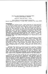
RESULTS AND DISCUSSION<br />
Typical weight loss versus time curves for devol<strong>at</strong>iliz<strong>at</strong>ion <strong>of</strong> PSOC-1133 (LV<br />
<strong>coal</strong>) are presented in Figure 1. This plot shows weight loss is essentially complete<br />
within <strong>the</strong> first 100 msec <strong>of</strong> residence time. The same behavior was observed for<br />
<strong>the</strong> HVA <strong>coal</strong> examined in this study. These results are in good agreement with th<strong>at</strong><br />
<strong>of</strong> Badzioch and Hawksley (10). In similar experimental systems it is <strong>of</strong>ten assumed<br />
th<strong>at</strong> pyrolysis occurs iso<strong>the</strong>rmally (7-10), however, this assumption cannot be made<br />
for <strong>the</strong> <strong>coal</strong>s analyzed here.<br />
Figure 1 also shows <strong>the</strong> maximum weight loss for devol<strong>at</strong>iliz<strong>at</strong>ion <strong>at</strong> 900°C is<br />
gre<strong>at</strong>er than <strong>at</strong> 1000°C. Similar observ<strong>at</strong>ions have been reported by Menster et al.<br />
(11,lZ). These authors suggest a possible explan<strong>at</strong>ion for this behavior which involves<br />
a competition between bond breaking reactions (which result in vol<strong>at</strong>ile form<strong>at</strong>ion)<br />
and secondary recombin<strong>at</strong>ion or polymeriz<strong>at</strong>ion (char forming) reactions,<br />
Figures 2 and 3 demonstr<strong>at</strong>e <strong>the</strong> effects <strong>of</strong> preoxid<strong>at</strong>ion on devol<strong>at</strong>iliz<strong>at</strong>ion<br />
behavior. Oxid<strong>at</strong>ion appears to have little effect on <strong>the</strong> r<strong>at</strong>e <strong>of</strong> pyrolysis, how-<br />
ever, devol<strong>at</strong>iliz<strong>at</strong>ion occurs so rapidly th<strong>at</strong> <strong>the</strong> time resolution <strong>of</strong> this system<br />
may be inadequ<strong>at</strong>e to distinguish such effects. Preoxid<strong>at</strong>ion reduces <strong>the</strong> yield <strong>of</strong><br />
vol<strong>at</strong>ile m<strong>at</strong>erial in all cases examined. This corresponds with a sharp decrease<br />
26<br />
105<br />
24.2
I<br />
'<br />
in <strong>the</strong> amount <strong>of</strong> condensible products (tars) collected." Increases in <strong>the</strong> level<br />
<strong>of</strong> oxid<strong>at</strong>ion prior to pyrolysis result in a progressive reduction in <strong>the</strong> yield <strong>of</strong><br />
vol<strong>at</strong>ile m<strong>at</strong>erial. Devol<strong>at</strong>iliz<strong>at</strong>ion curves for preoxidized <strong>coal</strong>s all have <strong>the</strong> same<br />
I characteristic shape. Weight loss passes through a shallow minimum with residence<br />
time. Fur<strong>the</strong>r study <strong>of</strong> this behavior is in progress.<br />
Figure 4 shows an electron micrograph <strong>of</strong> PSOC-1133 char collected after 330<br />
msec residence time <strong>at</strong> 1000"~. Coal structure has undergone extensive physical<br />
changes during <strong>the</strong> pyrolysis process. These chars are thin walled transparent<br />
structures commonly called cenospheres (13), <strong>the</strong> average diameter <strong>of</strong> which is three<br />
times th<strong>at</strong> <strong>of</strong> <strong>the</strong> starting <strong>coal</strong>. This represents a > 20 fold increase in volume.<br />
Similar results are obtained <strong>at</strong> 900°C and for PSOC-1099 <strong>at</strong> each temper<strong>at</strong>ure studied.<br />
Under <strong>the</strong> pyrolysis conditions employed in this work cenospheres are fully developed<br />
during <strong>the</strong> early stages <strong>of</strong> pyrolysis (< 40 msec) after which no detectable changes<br />
in macroscopic <strong>properties</strong> are observed.<br />
Figure 5 is a micrograph <strong>of</strong> a preoxidized <strong>coal</strong> char (PSOC-1133, 1% oxygen added)<br />
collected after 330 msec residence time <strong>at</strong> 1000°C. These chars do not form <strong>the</strong><br />
cenosphere structures exhibited by <strong>the</strong> unoxidized <strong>coal</strong>s. Char particles are rounded<br />
in shape indic<strong>at</strong>ing th<strong>at</strong> <strong>the</strong> <strong>coal</strong> passes through a plastic transition during carboniz<strong>at</strong>ion<br />
but no significant swelling is observed.<br />
SUPIMARY<br />
The sharp contrast in macroscopic <strong>properties</strong> <strong>of</strong> <strong>the</strong> chars collected in this<br />
study give rise to several important questions regarding char gasific<strong>at</strong>ion. Varying<br />
he<strong>at</strong> tre<strong>at</strong>ment conditions and <strong>coal</strong>. feed stocks give rise to chars <strong>of</strong> widely varying<br />
structure. In order to understand <strong>the</strong> behavior <strong>of</strong> <strong>the</strong>se m<strong>at</strong>erials in subsequent<br />
gasific<strong>at</strong>ion steps a more detailed analysis <strong>of</strong> char structure is required. At present<br />
microstructural <strong>properties</strong> (surface areas, porosities) <strong>of</strong> <strong>the</strong> chars gener<strong>at</strong>ed in<br />
this study are being examined in an effort to better understand <strong>the</strong> rel<strong>at</strong>ionship<br />
between char structure and he<strong>at</strong> tre<strong>at</strong>ment conditions. Results <strong>of</strong> this work will<br />
be available shortly.<br />
ACKNOWLEDGEMENTS<br />
Financial support for this work was provided by <strong>the</strong> Cooper<strong>at</strong>ive Program in<br />
Coal Research <strong>at</strong> The Pennsylvania St<strong>at</strong>e University. Coal samples were obtained<br />
from <strong>the</strong> Penn St<strong>at</strong>e/DOE <strong>coal</strong> sample bank.<br />
*Tar yields were not measured quantit<strong>at</strong>ively in this work, however, <strong>the</strong> differences<br />
in <strong>the</strong> amounts <strong>of</strong> condensible m<strong>at</strong>erials collected in <strong>the</strong> filtering systems were<br />
substantial enough to warrant <strong>the</strong> above comment.<br />
27
1. .<br />
2.<br />
3.<br />
4.<br />
5.<br />
6.<br />
7.<br />
8.<br />
9.<br />
REFERENCES<br />
Mahajan, 0. P. and Walker, P. L., Jr., "Analytical Methods for Coal and Coal<br />
Products," Vol. 2, (C. Karr, Editor), Academic Press, New York, 1978, pp. 465-<br />
494.<br />
Badzioch, S., B.C.U.R.A. Monthly Bull., 25, 285, 1961.<br />
Jones, W. Idris, J. Inst. Ful., 37, 3, 1964.<br />
Yellow, P. C., B.C.U.R.A. Monthly Bull., 9, 285, 1965.<br />
Badzioch, S., Field, M. A., Gill, D. W., Morgan, B. B., and Hawksley, P. G. W.,<br />
B.C.U.R.A. Month1.y Bull., 2, 193, 1967.<br />
Anthony, D. B. and Howard, J. B., A.1.Ch.E. Journal, 22, 625, 1976.<br />
Scaroni, A. W., Walker, P. L., Jr., and Essenhigh, R. H., ACS Div. Fuel Chem.,<br />
Preprints, E, No. 2, 123, Sept. 1979.<br />
Scaroni, A. W., Walker, P. L., Jr., and Essenhigh, R. H., Fuel., 9, 71, 1981.<br />
Nsakala, N., Essenhigh, R. H., and Walker, P. L., Jr., Comb. Sci. and Tech.,<br />
- 16, 153, 1977.<br />
10. Badzioch, S. and Hawksley, P.<br />
- 9, 521, 1970.<br />
11. Menster, M., O'Donnell, H. J.,<br />
Advances in Chemistry Series<br />
12. Menster, M., O'Donnell, H. J.<br />
- 14, No. 5, 94, 1970.<br />
13. Newall, H. E. and Sinn<strong>at</strong>t, F.<br />
G. W., Ind. Eng. Chem. Process Des. Develop.,<br />
Ergun, S., and Friedel, R. A., "Coal Gasific<strong>at</strong>ion,"<br />
31, Am. Chem. SOC., Washington, D. C., 1974.<br />
and Ergun, S., ACS Div. Fuel Chem., Preprints,<br />
S., Fuel, 2, 424, 1924.<br />
28
\<br />
I I<br />
0<br />
Residence Tim, SCC<br />
- 900.C . - 1000-C<br />
Figure I. WEICIiT LOSS AS A FUNCTION OF RESIUESCE TIM€ FOR PSOC-I131<br />
0.1 0.2 0.3<br />
mesldence ~ine.<br />
+ - R.1" COAI<br />
0 - 0.5% oxygen nddm<br />
A - 1% Oxygen addcd<br />
Flwre 2. WEICBT LOSS VERSUS RESIDENCE TIHE AS A FUNCTION OF PREOXIOATIOB LEVEL<br />
FOR PSoc-1133<br />
50<br />
.. 40<br />
x 30<br />
a 20<br />
10<br />
0.1 0.2 0.3<br />
Reridcncc Tim. sec<br />
Figure 3. WEIGHT LOSS VERSUS RESIDENCE TlHE AS A FUNCTION OF PRUIXIDATTON LEVEL<br />
FOR P%X-LO99<br />
29
Figure 4. SCANNING ELECTRON MICROGRAPH OF PSOC-1133 CHAR<br />
330 msec Residence Time <strong>at</strong> 1000°C<br />
Figure 5. SCANNING ELECTRON MICROGRAPH OF A PREOXIDIZED COAL CHAR<br />
(PSOC-1133 1% Oxygen Added) 330 msec Residence Time <strong>at</strong><br />
looooc<br />
30
Introduction<br />
INFLUENCE OF PARTICLE STRUCTURE CHANGES ON THE<br />
RATE OF COAL CHAR REACTION WITH C02<br />
K. A. Debelak, M. A. Clark and J. T. Malito<br />
Department <strong>of</strong> Chemical Engineering<br />
Vanderbi 1 t University<br />
Nashville, TN 37235<br />
A coiiunon fe<strong>at</strong>ure <strong>of</strong> gas-solid reactions is th<strong>at</strong> <strong>the</strong> overall process involves<br />
several steps: (1) mass transfer <strong>of</strong> reactants and products from bulk gas phase<br />
to <strong>the</strong> internal surface <strong>of</strong> <strong>the</strong> reacting solid particle; (2) diffusion <strong>of</strong> gaseous<br />
reactants or products through <strong>the</strong> pores <strong>of</strong> a solid reactant; (3) adsorption<br />
<strong>of</strong> gaseous reactants on sol id reactant sites and desorption <strong>of</strong> reaction products<br />
from solid surfaces; (4) <strong>the</strong> actual chemical reaction between <strong>the</strong> adsorbed<br />
gas and solid.<br />
In studying gas-solid reactants, we are concerned with <strong>the</strong>se four phenomena<br />
and o<strong>the</strong>r phenomena which affect <strong>the</strong> overall r<strong>at</strong>e <strong>of</strong> reaction and performance<br />
<strong>of</strong> industrial equipment in which <strong>the</strong>se gas-solid reactions are carried out.<br />
These o<strong>the</strong>r phenomena include:<br />
he<strong>at</strong> transfer, flow <strong>of</strong> gases and solids through<br />
reactors, and changes in <strong>the</strong> solid structure, all <strong>of</strong> which affect <strong>the</strong> r<strong>at</strong>e <strong>of</strong><br />
diffusion and surface area available for reaction. The reaction to be studied<br />
is <strong>the</strong> reaction between carbon and carbon dioxide to form carbon monoxide.<br />
This reaction is <strong>of</strong> importance for it is one o f <strong>the</strong> prime reactions occurring<br />
in <strong>coal</strong> gasifiers, and also it is a reaction on which <strong>the</strong>re is d<strong>at</strong>a from o<strong>the</strong>r<br />
investig<strong>at</strong>ions (1-17). Considerable discrepancy has been found for activ<strong>at</strong>ion<br />
energies which ranges from 48-86 kcal/mol and for reaction r<strong>at</strong>e constants.<br />
This can be explained by <strong>the</strong> somewh<strong>at</strong> oversimplified view <strong>of</strong> <strong>the</strong> mechanism which<br />
was thought to be r<strong>at</strong>e-controlling, and <strong>the</strong> simplific<strong>at</strong>ion made in <strong>the</strong> corres-<br />
ponding reaction r<strong>at</strong>e models.<br />
Gulbransen and Andrew (2) showed th<strong>at</strong> <strong>the</strong> internal surface area <strong>of</strong> graphite<br />
increased during reaction with carbon dioxide and oxygen, Walker et al. (3)<br />
studied graphite rods for <strong>the</strong> possible correl<strong>at</strong>ions existing between reaction<br />
r<strong>at</strong>es and changes in surface area during reaction. They concluded th<strong>at</strong> <strong>the</strong><br />
reaction develops new surface, to some extent, by enlarging <strong>the</strong> micropores<br />
<strong>of</strong> <strong>the</strong> solid but principally by opening up pore volume not previously available<br />
to reactant gas ei<strong>the</strong>r because <strong>the</strong> capillaries were too small or because existing<br />
pores were unconnected. Surface area increased up to a point where r<strong>at</strong>e <strong>of</strong><br />
production <strong>of</strong> new surface equalled <strong>the</strong> destruction <strong>of</strong> old surface, after which<br />
surface area <strong>the</strong>n continued to decrease. For <strong>the</strong> graphite-carbon dioxide<br />
reaction, Petersen (4) found th<strong>at</strong> observed r<strong>at</strong>es were not simple functions <strong>of</strong><br />
<strong>the</strong> total available surface area as determined by low-temper<strong>at</strong>ure adsorptions<br />
prior to reaction, as might be expected if <strong>the</strong> reaction was chemical-reaction<br />
control 1 ed.<br />
31
Turkgodan et al. (18) studied <strong>the</strong> pore characteristics <strong>of</strong> several carbons,<br />
graphite, coke and char<strong>coal</strong>. They concluded thdt about 1/2 <strong>of</strong> <strong>the</strong> volume is<br />
loc<strong>at</strong>ed in micropores and <strong>the</strong>refore not avdilable for reaction, Most <strong>of</strong> <strong>the</strong><br />
internal surface area was loc<strong>at</strong>ed in pores in <strong>the</strong> micropore range. The pore<br />
vol unie, pore surface area, and effective di ffusi vi ty increased with conversion<br />
during internal oxid<strong>at</strong>ion,<br />
Dutta and Wen (16, 17) studied <strong>the</strong> reactivities <strong>of</strong> several raw <strong>coal</strong>s and<br />
chars. They noted a change in <strong>the</strong> actual pore structures <strong>of</strong> a few samples <strong>at</strong><br />
di Fferent conversions from scanning electron micrographs. A r<strong>at</strong>e equ<strong>at</strong>ion<br />
was proposed th<strong>at</strong> incorpor<strong>at</strong>ed <strong>the</strong> change <strong>of</strong> <strong>the</strong> rel<strong>at</strong>ive available surface<br />
area during reaction. No measurements <strong>of</strong> this change were made. A r<strong>at</strong>e<br />
expression, which includes <strong>the</strong> influence <strong>of</strong> a chemical and diffusion reaction<br />
controlling niechanisnis, is expressed<br />
where:<br />
c=<br />
dX<br />
dt rl s k c<br />
c02<br />
(l-xc)<br />
Xc is <strong>the</strong> conversion <strong>of</strong> <strong>the</strong> solid<br />
S is <strong>the</strong> surface area available for reaction<br />
k is <strong>the</strong> reaction r<strong>at</strong>e constant<br />
rl is <strong>the</strong> effectiveness factor<br />
is <strong>the</strong> concentr<strong>at</strong>ion <strong>of</strong> C02 in gas phase<br />
cco2<br />
t is time<br />
The effectiveness factor n is equal to <strong>the</strong> r<strong>at</strong>io <strong>of</strong> <strong>the</strong> reaction r<strong>at</strong>e under<br />
diffusion-controlled conditions to th<strong>at</strong> which would occur if <strong>the</strong> concentr<strong>at</strong>ion<br />
<strong>of</strong> reactants were equal to <strong>the</strong> surface concentr<strong>at</strong>ion. For a first order diffu-<br />
sion-controlled reaction <strong>the</strong> influence <strong>of</strong> pore-diffusion is given by equ<strong>at</strong>ion 2)<br />
where :<br />
S is <strong>the</strong> specific surface<br />
k is <strong>the</strong> reaction r<strong>at</strong>e constant<br />
rc is <strong>the</strong> radius <strong>of</strong> <strong>the</strong> particle<br />
De is <strong>the</strong> effective diffusivity<br />
The effectiveness factor n is a function <strong>of</strong> <strong>the</strong> effective modulus, $, which<br />
is dependent upon <strong>the</strong> effective diffusivity, D . The effective diffusivity<br />
and <strong>the</strong> surface area available for reaction chgnge during <strong>the</strong> reaction,<br />
32<br />
1)
I<br />
1<br />
This itidy be expressed as<br />
s = so f iXC)<br />
De = D h (X,)<br />
en<br />
5)<br />
where So and De are <strong>the</strong> available surface area and effective diffusivity<br />
<strong>at</strong> zero convers?on, and f(Xc) and h(Xc) are functions <strong>of</strong> conversion, Xc.<br />
deterillin<strong>at</strong>ion <strong>of</strong> <strong>the</strong>se changing parameters and <strong>the</strong>ir influence on <strong>the</strong><br />
overall reaction r<strong>at</strong>e is <strong>the</strong> objective <strong>of</strong> this research.<br />
Effective Diffusi vi ty<br />
I. Theoretical Development <strong>of</strong> Model<br />
Experiinental determin<strong>at</strong>ion <strong>of</strong> <strong>the</strong> effective diffusivity in <strong>coal</strong> is performed<br />
in a packed bed <strong>of</strong> <strong>coal</strong> particles with a carrier gas flowing through <strong>the</strong><br />
bed. A pulse in <strong>the</strong> concentr<strong>at</strong>ion <strong>of</strong> <strong>the</strong> adsorb<strong>at</strong>e gas is introduced<br />
<strong>at</strong> <strong>the</strong> inlet <strong>of</strong> <strong>the</strong> packed bed. The mass transfer characteristics <strong>of</strong><br />
<strong>the</strong> bed change <strong>the</strong> shape <strong>of</strong> <strong>the</strong> pulse as it passes through <strong>the</strong> bed.<br />
<strong>the</strong>oretical model describing <strong>the</strong> mass transfer in <strong>the</strong> bed is used to<br />
rel<strong>at</strong>e <strong>the</strong> unsteady st<strong>at</strong>e concentr<strong>at</strong>ion response in <strong>the</strong> bed effluent to<br />
<strong>the</strong> original pulse input. By applying <strong>the</strong> model to <strong>the</strong> experimental d<strong>at</strong>a,<br />
<strong>the</strong> parameters <strong>of</strong> <strong>the</strong> model are determined. The model describing <strong>the</strong> mass<br />
transfer in <strong>the</strong> packed bed consists <strong>of</strong> unsteady st<strong>at</strong>e m<strong>at</strong>erial balances<br />
in <strong>the</strong> packed bed and <strong>the</strong> <strong>coal</strong> particles. Equ<strong>at</strong>ions (6-14) describe <strong>the</strong><br />
mass transfer in <strong>the</strong> packed bed <strong>of</strong> particles and <strong>the</strong> boundary conditions.<br />
M<strong>at</strong>erial balance on <strong>coal</strong> particle<br />
Rel<strong>at</strong>i.on between adsorbed concentr<strong>at</strong>ion and concentr<strong>at</strong>ion <strong>of</strong> surface<br />
Boundary condi t<br />
ons<br />
q(rc, t) = KcC (rc. t)<br />
3 (0, t) = 0<br />
33<br />
4)<br />
A<br />
The
M<strong>at</strong>eridl balance on packed bed<br />
Boundary conditions<br />
11. Solution <strong>of</strong> <strong>the</strong> Model<br />
r)<br />
Three altern<strong>at</strong>ive techniques for solution and subsequent parameter<br />
estim<strong>at</strong>ion from <strong>the</strong> model are curve fitting in <strong>the</strong> time domain, curve<br />
fitting in <strong>the</strong> Laplace or Fourier domain, and <strong>the</strong> method <strong>of</strong> moments.<br />
Moments <strong>of</strong> <strong>the</strong> response curve resulting from a pulse input can be solved<br />
analytically for <strong>the</strong> solution to <strong>the</strong> model in <strong>the</strong> Laplace domain. Parameter<br />
estim<strong>at</strong>ion is achieved by m<strong>at</strong>ching <strong>the</strong> measured moments with <strong>the</strong><br />
analytical expression for <strong>the</strong> moments. The method <strong>of</strong> moments was used in<br />
this work because it does not require a numerical solution to <strong>the</strong> model and<br />
because parameters estim<strong>at</strong>ion can be performed in <strong>the</strong> time domain. The<br />
Laplace transform is applied to <strong>the</strong> time variable in <strong>the</strong> equ<strong>at</strong>ions and<br />
boundary conditions <strong>of</strong> <strong>the</strong> model.<br />
A system <strong>of</strong> coupled ordinary differential<br />
equ<strong>at</strong>ions is obtained after applying this transform. A <strong>the</strong>orem rel<strong>at</strong>ing<br />
<strong>the</strong> transformed solution to <strong>the</strong> absolute and central moments <strong>of</strong> time<br />
domain solution is<br />
The nth absolute moment<br />
dn -<br />
M, = (-1)” lim - c (s, z)<br />
SO dsn<br />
is defined as:<br />
lq - -<br />
8 - Mn<br />
M =<br />
n<br />
0”<br />
The nth central moment is defined by:<br />
MO<br />
Applying equ<strong>at</strong>ion 15) to <strong>the</strong> transformed solution <strong>of</strong> <strong>the</strong> model results<br />
in <strong>the</strong> following equ<strong>at</strong>ions for <strong>the</strong> first absolute and second central moments:<br />
34
I<br />
These two equ<strong>at</strong>ions rel<strong>at</strong>e <strong>the</strong> model parameters to <strong>the</strong> moments which can<br />
be calcul<strong>at</strong>ed from experimental d<strong>at</strong>a.<br />
Experi!!iental<br />
WYODAK subbituminous <strong>coal</strong>, particle size 35 x 60, was used in <strong>the</strong><br />
experimental study. The experimental system consisted <strong>of</strong> a pulse reactor,<br />
Figure 1, a flow type BET appar<strong>at</strong>us, Figure 2, and <strong>the</strong> chrom<strong>at</strong>ographic<br />
appar<strong>at</strong>us, Figure 3. This allowed determin<strong>at</strong>ions <strong>of</strong> surface area and<br />
effective diffusivity to be made in conjunction with reaction studies<br />
without removing <strong>the</strong> sample.<br />
Measurements <strong>of</strong> surface area and effective diffusivi ty were made on raw<br />
<strong>coal</strong>s. Surface area measurements were made by adsorbing carbon dioxide<br />
<strong>at</strong> 195 K for 30 minutes. The single point BET method was used for evalu<strong>at</strong>ion<br />
<strong>of</strong> <strong>the</strong> surface area. The raw <strong>coal</strong>s were devol<strong>at</strong>ilized by he<strong>at</strong>ing <strong>at</strong><br />
SoC/min to a temper<strong>at</strong>ure <strong>of</strong> 8OO0C to produce a <strong>coal</strong> char. Changes in surface<br />
area and effective diffusivity were again detprmined. The <strong>coal</strong> char<br />
was <strong>the</strong>n partially reacted <strong>at</strong> a temper<strong>at</strong>ure <strong>of</strong> 800 C by injecting a known<br />
volume <strong>of</strong> carbon dioxide. Changes in surface area and effective diffusivity<br />
were again determined. This procedure was repe<strong>at</strong>ed until <strong>the</strong> conversion<br />
<strong>of</strong> <strong>the</strong> carbon in <strong>the</strong> <strong>coal</strong> approached 1.0.<br />
Results and Discussion<br />
The devol<strong>at</strong>iliz<strong>at</strong>ion caused structural changes which are reflected in an<br />
average weight loss <strong>of</strong> 41% <strong>of</strong> <strong>the</strong> initial weight, a decrease in <strong>the</strong> diffusion<br />
coefficient, and an increase in total surface area. Table 1 gives<br />
<strong>the</strong>se changes for three WYOOAK samples. The increase in surface area represents<br />
<strong>the</strong> opening <strong>of</strong> pores which were not accessible before devol<strong>at</strong>iliz<strong>at</strong>ion.<br />
Walls closing <strong>of</strong>f pores are devol<strong>at</strong>ilized and small pores inaccessible to<br />
<strong>the</strong> initial CO adsorption are enlarged because <strong>of</strong> <strong>the</strong> evolution <strong>of</strong> vol<strong>at</strong>ile<br />
m<strong>at</strong>erial durin5 <strong>the</strong> he<strong>at</strong>ing, This new pore structure has a gre<strong>at</strong>er resistance<br />
to diffusion, seen as a decrease in <strong>the</strong> diffusion coefficient. The<br />
small pores and enlarged pore form a more complex network <strong>of</strong> voids within<br />
<strong>the</strong> particles.<br />
increase in total available surface area and a decrease in <strong>the</strong> diffusion<br />
coef f i ci ent .<br />
The heterogeneous chemical reaction causes continuous changes in <strong>the</strong> pore<br />
structure due to <strong>the</strong> consumption <strong>of</strong> carbon. Pore walls are being gasified<br />
slowly as <strong>the</strong> reaction continues toward completton. The continually<br />
changing internal structure affects <strong>the</strong> diffusion <strong>of</strong> gaseous reactants<br />
and products to and from <strong>the</strong> active carbon sites within <strong>the</strong> particle.<br />
19)<br />
The production <strong>of</strong> char by devol<strong>at</strong>iliz<strong>at</strong>ion causes an<br />
35
These phenomena iiiay be described by examining Figure 4 which is a plot<br />
<strong>of</strong> <strong>the</strong> diffusion coefficient d<strong>at</strong>a for <strong>the</strong> three WYODAK samples measured<br />
<strong>at</strong> various carbon conversions, The diffusion coefficient increases slowly<br />
<strong>at</strong> low conversion and is soinewhdt stable during <strong>the</strong> mid-range <strong>of</strong> conversion,<br />
but increases very quickly as <strong>the</strong> reaction nears completion. Overall <strong>the</strong><br />
diffusion coefficient increases as carbon conversion inreases.<br />
can be correl<strong>at</strong>ed by<br />
These d<strong>at</strong>a (<br />
- DC = (0.06) exp (1.7 . Xc)<br />
r C<br />
which gave an index <strong>of</strong> determin<strong>at</strong>ion <strong>of</strong> 0.88. Physically, <strong>the</strong> pore<br />
structure after devol<strong>at</strong>iliz<strong>at</strong>ion consists <strong>of</strong> a small amount <strong>of</strong> void, charac-<br />
teristic <strong>of</strong> <strong>the</strong> low diffusion coefficient which means th<strong>at</strong> <strong>the</strong> resistance to<br />
diffusion is substantial. During reaction <strong>the</strong>se pores gradually enlarge due<br />
to gasific<strong>at</strong>ion <strong>of</strong> <strong>the</strong> carbon. Therefore as conversion increases <strong>the</strong> pore<br />
volume or void increases resulting in less resistance to diffusion, which<br />
is reflected by <strong>the</strong> increase in <strong>the</strong> diffusion coefficient.<br />
The CD2-char reaction occurs <strong>at</strong> active carbon sites upon <strong>the</strong> <strong>coal</strong> char<br />
surface. Thus <strong>the</strong> consumption <strong>of</strong> <strong>the</strong> reactant carbon will affect <strong>the</strong> total<br />
surface area. The total surface area decreases for <strong>the</strong>se WYODAK samples<br />
as <strong>the</strong> carbon conversion increases, Figure 5. As conversion goes toward<br />
completion, pore walls which are measured as surface area are gasified<br />
or consumed by <strong>the</strong> reaction causing a decrease in total surface area.<br />
Figure 5 shows <strong>the</strong> specific surface area versus <strong>the</strong> carbon conversion.<br />
The specific surface area first goes through a minimum <strong>at</strong> low carbon con-<br />
versions and <strong>the</strong>n a maximum as carbon conversion goes toward completion.<br />
Mahajan and Walker (19) predicted <strong>the</strong> maximum in <strong>the</strong>ir qualit<strong>at</strong>ive descrip-<br />
tion <strong>of</strong> <strong>the</strong> reaction process. Dutta and Wen (16) found th<strong>at</strong> <strong>the</strong> reaction<br />
r<strong>at</strong>e reaches amaximum <strong>at</strong> a carbon conversion <strong>of</strong> approxim<strong>at</strong>ely 0.2 for reac-<br />
tions carried out <strong>at</strong> low temper<strong>at</strong>ures. In an <strong>at</strong>tempt to correl<strong>at</strong>e this d<strong>at</strong>a<br />
<strong>the</strong>y assumed a reaction r<strong>at</strong>e model, Equ<strong>at</strong>ion 1). for <strong>the</strong> chemical controlled<br />
regime. They incorpor<strong>at</strong>ed into <strong>the</strong> model a proposed function <strong>of</strong> conversion<br />
which describes changes in surface area.<br />
a = 1 2 100 x"," exp (-Bx,-)<br />
where a equals <strong>the</strong> specific surface area divided by <strong>the</strong> initial specific<br />
surface area. Fitting <strong>the</strong> model to <strong>the</strong> reaction r<strong>at</strong>e versus conversion<br />
d<strong>at</strong>a <strong>the</strong> parameters <strong>of</strong> <strong>the</strong> proposed function were estim<strong>at</strong>ed by Dutta and<br />
Wen (16). This function describing changes in specific surface area<br />
exhibits a maximum <strong>at</strong> approxim<strong>at</strong>ely <strong>the</strong> same conversion as our d<strong>at</strong>a.<br />
At low temper<strong>at</strong>ures where reaction r<strong>at</strong>e is predominantly chemically<br />
controlled, <strong>the</strong> maximum in <strong>the</strong> reaction r<strong>at</strong>e vs. conversion d<strong>at</strong>a can be<br />
36<br />
21 1<br />
!
explained by <strong>the</strong> fact th<strong>at</strong> <strong>the</strong> specific surface for chemical reaction<br />
also goes through a maximum and this behavior <strong>of</strong> <strong>the</strong> specific area has<br />
been experimentally confirmed. The problem with equ<strong>at</strong>ion 22) is th<strong>at</strong> it<br />
predicts ei<strong>the</strong>r a maximum or minimum for <strong>the</strong> value <strong>of</strong> a, but not both.<br />
In a recent paper Bh<strong>at</strong>ia and Perlmuter (20), using a random pore model<br />
have derived an expression for surface area as a function <strong>of</strong> converslon<br />
where L , S and E are <strong>the</strong> initial total pore length, surface area<br />
to volu8e rstio, a8d porosity respectively. This equ<strong>at</strong>ion correl<strong>at</strong>es<br />
our d<strong>at</strong>a predicting both a minimum and maximum in values <strong>of</strong> specific<br />
surface area, Figure 6.<br />
Acknowledgements<br />
This work was supported by a N<strong>at</strong>ional Science Found<strong>at</strong>ion Research<br />
Institution Grant, Eng. 7907988.<br />
References<br />
Gadsby, J., Long, F. J.. Sleighthom, P., and Sykes, K. W.,<br />
"The Mechanism <strong>of</strong> <strong>the</strong> Carbon Dioxide Reaction," Proc. Roy.<br />
SOC, London, Ser. A, 193, 377 (1948).<br />
Gulbransen, E. A., and Andrew, K. F., "Reaction <strong>of</strong> Carbon Dioxide<br />
with Pure Artificial Graphite <strong>at</strong> Temper<strong>at</strong>ures <strong>of</strong> 5OO0C," Ind. Eng.<br />
-- Chem., 44, 1039 (1952).\<br />
Walker, P. L., Foresti, R. J. and Wright, C. C., "Surface Area<br />
Studies <strong>of</strong> Carbon-Carbon Dioxide Reaction," Ind. Eng. Chem.,<br />
- 45, 8, 1703 (1953).<br />
Petersen, E. E., Walker, P. L. and Wright, C. C., "Surface Area<br />
Development Within Artificial Graphite Rods Reacted with Carbon<br />
Dioxide from 900°C to 1300oC," Ind. Eng. Chem., 47, 1629 (1955).<br />
Wicke. E., "Fifth Symposium on Combustion," p. 245, Reinhold,<br />
New York, New York (1955).<br />
Rossberg, V. M., and Wicke, E., "Transportvogage and Oberflachem-<br />
reaktionen bei der Verbrennung Graphi ti schen Kohlenst<strong>of</strong>f ,I' Chem. Ing.<br />
Tech., 28, 191 (1956).<br />
Ergun, S., "Kinetics <strong>of</strong> <strong>the</strong> Reaction <strong>of</strong> Carbon Dioxide with Carbon,"<br />
J. Phys. Chem., 60, 480 (1956).<br />
37
Walker, P. L., Rusinko, F., and Austin, L. G., "Gas Reactions<br />
Carbon," Advances in C<strong>at</strong>alysis, Vol. XI, 133-221 (1959).<br />
Austin, L. G. and Walker, P. L., "Effect <strong>of</strong> Carbon Monoxide in<br />
Causing Nonuniforni Gasific<strong>at</strong>ion <strong>of</strong> Graphite by Carbon Dioxide,"<br />
AIChE Journal, 9, 303 (1963).<br />
Turkdogan, E. T., Kaoump, V., Vinters, J. V., "R<strong>at</strong>e <strong>of</strong> Oxid<strong>at</strong>ion<br />
<strong>of</strong> Graphite in Carbon Dioxide," Carbon, 5, 467 (1968).<br />
Turkdogan, E. T., Vinters, J. V., "Kinetics <strong>of</strong> Oxid<strong>at</strong>ion <strong>of</strong><br />
Graphite and Char<strong>coal</strong> in C02," Carbon, 7, 101 (1969).<br />
Yoshida, K., and Kinii, D., "Gasific<strong>at</strong>ion <strong>of</strong> Porous Carbon by<br />
Carbon Dioxides," J. Chem. Engr., Japan, 2, 170 (1969).<br />
Wen, C. Y., and Wy, N. T., "An Analysis <strong>of</strong> Slow Reactions in a<br />
Porous Particle," AIChE Journal, 20, 5, 833-840 (1974).<br />
Walker, P. L, and Hippo, E., "Reactivity <strong>of</strong> He<strong>at</strong>-Tre<strong>at</strong>ed Coals<br />
in Carbon Dioxide <strong>at</strong> 900°C," m, 54, 245 (1975).<br />
Fuchs, W., Yavarsky, P. M., "Am. Chem. SOC., Div. Fuel Chem. ,"<br />
20 (3), 115, (1975).<br />
Dutta, S., Wen, C. Y., "Reactivity <strong>of</strong> Coal and Char. 2. In<br />
Oxygen-Nitrogen Atmosphere," Ind. Eng. Chem.,<br />
- 16, No. 1, 20 (1977).<br />
Process Des. Dev.,<br />
Dutta, S., Wen, C. Y., "Reactivity <strong>of</strong> Coal and Char, 2. In<br />
Oxygen-Ni trogen Atmosphere ," Ind. Eng , Chem., Process Des. Dev.,<br />
- 16, No. 1, 31 (1977).<br />
Turkdogan, E. T., Olsson, R. G., and Vinters, J, V,, "Pore<br />
Characteristics <strong>of</strong> Carbon ," Carbon, 8, 545-564 (1970).<br />
Mahajan, A. P., Yarzab, R., and Walker, P. L., Jr,, "Unific<strong>at</strong>ion<br />
<strong>of</strong> Coal-Char Gasific<strong>at</strong>ion Reaction Mechanisms,'' w, Vol. 57,<br />
pp. 643-646, October 1978.<br />
Bh<strong>at</strong>ia, S. K. and Perlmutter, D. D,, "A Randoni Pore Model for Fluid<br />
Solid Reactions: I. Iso<strong>the</strong>rnal, Kinetic Control", AIChE J.,<br />
- 26, NO. 3, 379-385 (1980).<br />
38<br />
I
TI<br />
39
-""I-<br />
*I,".. I Dlrf".,on Co.1flcl.n. ....<br />
". Car.r.9""<br />
40
AN ENTRAINED FLOW REACTOR WITH IN SITU FTIR ANALYSIS*<br />
Peter R. Solomon and David G. Hamblen<br />
Advanced Fuel Research, Inc. 87 Church St., East Hartford, CT 06108<br />
I<br />
\ INTRODUCTION<br />
\<br />
I<br />
A key element in predicting <strong>coal</strong> gasific<strong>at</strong>ion behavior is pyrolysis. This is <strong>the</strong><br />
initial step in gasific<strong>at</strong>ion, <strong>the</strong> step which controls <strong>the</strong> amount and physical<br />
Structure <strong>of</strong> <strong>the</strong> char and <strong>the</strong> step which is most dependent on <strong>the</strong> <strong>properties</strong> <strong>of</strong> <strong>the</strong><br />
<strong>coal</strong>. Recent reviews <strong>of</strong> <strong>coal</strong> pyrolysis (1,2,3) conclude th<strong>at</strong> <strong>the</strong> pyrolysis product<br />
distribution and apparent kinetic r<strong>at</strong>es vary widely with <strong>the</strong> experimental<br />
measurement. It is clear th<strong>at</strong> to establish a true predictive capability additional<br />
work is needed to understand pyrolysis reactions and define usable r<strong>at</strong>es.<br />
Among <strong>the</strong> experiments which have been useful in investig<strong>at</strong>ing pyrolysis have been<br />
<strong>the</strong> captive sample he<strong>at</strong>ed grid devices which have achieved good mass and elemental<br />
balances and have provided d<strong>at</strong>a on individual species evolution (4-16). However,<br />
<strong>the</strong> he<strong>at</strong>ing <strong>of</strong> <strong>the</strong> <strong>coal</strong> is slower than in practical devices so th<strong>at</strong> <strong>the</strong> kinetic d<strong>at</strong>a<br />
is <strong>of</strong> limited value.<br />
Entrained flow reactors which provide more realistic particle he<strong>at</strong>ing have been<br />
employed to study pyrolysis weight loss but have not provided much species evolution<br />
d<strong>at</strong>a (17-23). New visual d<strong>at</strong>a on pyrolysis behavior have been obtained in reactors<br />
with optical access (24, 25). These reactors employ fl<strong>at</strong> flame burners into which<br />
<strong>coal</strong> may be injected.<br />
This paper reports on a new appar<strong>at</strong>us which has been designed to combine <strong>the</strong><br />
advantages <strong>of</strong> <strong>the</strong> reactors described above. The new reactor: 1) injects <strong>coal</strong> into a<br />
prehe<strong>at</strong>ed gas stream in a hot furnace to provide rapid particle he<strong>at</strong>ing, 2) provides<br />
for optical access, 3) employs an FTIR for species concentr<strong>at</strong>ion measurements, both<br />
in-situ and in an external cell and 4 ) has provisions for obtaining mass balances.<br />
The reactor will be used in a program to study pyrolysis and secondary reactions <strong>of</strong><br />
interest in gasific<strong>at</strong>ion. The results will be used to test <strong>the</strong> conclusions <strong>of</strong> a<br />
previously developed pyrolysis model (11-15, 26-29) and fill in needed kinetic d<strong>at</strong>a.<br />
The paper describes <strong>the</strong> reactor, reports preliminary results obtained with four<br />
<strong>coal</strong>s <strong>at</strong> furnace temper<strong>at</strong>ures from 700°C to 1200°C and assesses how <strong>the</strong>se results<br />
compare to d<strong>at</strong>a obtained in o<strong>the</strong>r experiments.<br />
EXPERIMENTAL<br />
The reactor has been designed to study <strong>coal</strong> behavior under conditions <strong>of</strong> temper<strong>at</strong>ure<br />
and he<strong>at</strong>ing r<strong>at</strong>e encountered in an entrained flow gasifier. The schem<strong>at</strong>ic <strong>of</strong> <strong>the</strong><br />
experiment is presented in Fig. 1. A gas stream <strong>of</strong> predetermined composition is<br />
he<strong>at</strong>ed during transit through a bed <strong>of</strong> alumina chips maintained <strong>at</strong> furnace<br />
temper<strong>at</strong>ure. (Prior to he<strong>at</strong>ing, <strong>the</strong> gas composition can be analyzed by routing <strong>the</strong><br />
stream through an infrared cell). The gas stream <strong>the</strong>n enters a test section,<br />
maintained <strong>at</strong> <strong>the</strong> furnace temper<strong>at</strong>ure, where <strong>coal</strong> is introduced through a w<strong>at</strong>er<br />
cooled injector. The <strong>coal</strong> is fed using a modific<strong>at</strong>ion <strong>of</strong> a MIT entrainment system<br />
(30). In <strong>the</strong> modified system, <strong>the</strong> feeder tube, which extends up through <strong>the</strong> <strong>coal</strong><br />
bed, is slowly lowered as <strong>the</strong> entrainment gas (injected above <strong>the</strong> bed) exits through<br />
<strong>the</strong> tube. When <strong>the</strong> tube feeder entrance is <strong>at</strong> <strong>the</strong> level <strong>of</strong> <strong>the</strong> bed, <strong>coal</strong> is<br />
entrained in <strong>the</strong> gas and enters <strong>the</strong> tube. The r<strong>at</strong>e for <strong>coal</strong> feeding is controlled<br />
by <strong>the</strong> r<strong>at</strong>e <strong>at</strong> which <strong>the</strong> tube is lowered.<br />
* This program was initi<strong>at</strong>ed under EPRI contract #RP 1654-8. The program<br />
scope is currently being expanded under contract #DE AC01-81FE05122 from <strong>the</strong><br />
US Department <strong>of</strong> Energy.<br />
41
After a variable residence time, <strong>the</strong> reacting stream passes optical access ports and<br />
immedi<strong>at</strong>ely downstream is quenched in a w<strong>at</strong>er cooled collector. There are five ?<br />
optical access ports, two <strong>of</strong> which are presently employed for <strong>the</strong> FTIR beam. The<br />
o<strong>the</strong>r three ports are available for additional diagnostics. The quenched stream <strong>of</strong> I<br />
char, tar and gases enters a cyclone designed to separ<strong>at</strong>e particles larger than 4<br />
microns (31) and <strong>the</strong>n enters a series <strong>of</strong> filters to remove and sample <strong>the</strong> tar and (<br />
soot. The clean gas stream <strong>the</strong>n enters <strong>the</strong> room temper<strong>at</strong>ure FTIR cell which<br />
/<br />
provides a longer p<strong>at</strong>h length for higher sensitivity analysis. The particle<br />
residence time can be varied from 0 to 700 msec and <strong>the</strong> furnace has been designed to<br />
oper<strong>at</strong>e up to 1650’C.<br />
The FTIR can quantit<strong>at</strong>ively determine many gas species observed in <strong>coal</strong> pyrolysis<br />
including CO, CO , H20, CH4, CZH2, C H4, C2H6, C4H8s C6H6, NH3, HCN,<br />
SO2, COS, CS ani heavy paraffins an% olefins. C$Et’i:ikment can take spectra<br />
2<br />
every 80 msec to follow rapid changes in <strong>the</strong> reactor or co-add spectra for long<br />
periods <strong>of</strong> steady st<strong>at</strong>e flow to increase signal to noise. FTIR is well suited to<br />
in-situ furnace experiments since <strong>the</strong> FTIR system oper<strong>at</strong>es by coding <strong>the</strong> infrared<br />
source with an amplitude modul<strong>at</strong>ion which is unique to each infrared frequency. The<br />
detector is sensitive to <strong>the</strong> modul<strong>at</strong>ed radi<strong>at</strong>ion so th<strong>at</strong> unmodul<strong>at</strong>ed stray radi<strong>at</strong>ion<br />
is elimin<strong>at</strong>ed from <strong>the</strong> experiment.<br />
In <strong>the</strong> work described below, experiments were run for <strong>the</strong> four <strong>coal</strong>s listed in<br />
Table 1. The <strong>coal</strong>s were sieved to produce a -200, +325 mesh size cut. The <strong>coal</strong> was<br />
fed <strong>at</strong> 2.4 grams/min. Helium was used for both <strong>the</strong> prehe<strong>at</strong>ed gas and <strong>the</strong><br />
entrainment gas.<br />
The prehe<strong>at</strong>ed gas was fed <strong>at</strong> r<strong>at</strong>es between 40 and 25 l/min<br />
depending on temper<strong>at</strong>ure to provide a gas velocity <strong>of</strong> 1 m/sec within <strong>the</strong> furnace.<br />
The entrainment gas was fed <strong>at</strong> 1.2 l/min. Infrared spectra were obtained with a<br />
Nicolet model 7199 FTIR using a globar source and a mercury-cadmium telluride<br />
detector. For obtaining <strong>the</strong> spectra within <strong>the</strong> furnace and within <strong>the</strong> cell, 100<br />
scans <strong>at</strong> 0.5 wavenumber resolutions were accumul<strong>at</strong>ed in 140 seconds and transformed<br />
in under 2 minutes.<br />
TABLE I<br />
COALS USED IN THE ENTRAINED FLOW REACTOR STUDY<br />
COAL TYPE UT% (DAF)<br />
c H N S 0 ASH (Dry)<br />
Savage Montana Lignite 71.2 4.6 1.1 1.3 21.8 10.6<br />
Jacobs Ranch Wyom. Scbbituminous 74.3 5.2 1.1 .6 18.8 7.8<br />
Illinois P6 Bituminous 73.9 5.1 1.4 4.2 15.4 11.0<br />
Pittsburgh 18 Bituminous 83.5 5.5 1.6 3.3 6.1 9.2<br />
Gas Analysis in <strong>the</strong> Furnace<br />
Figure 2 shows <strong>the</strong> in-situ gas analysis. There is an acceptable noise level and no<br />
drastic effects from <strong>the</strong> particle sc<strong>at</strong>tering. The analyses are for <strong>the</strong> <strong>coal</strong><br />
injector <strong>at</strong> positions from 5 to 66 cm above <strong>the</strong> optical port. The species which can<br />
easily be seen are CO, C02, H20, CH , C2H2, C H and heavy paraffins. Additional<br />
species could be observed through tke use <strong>of</strong> to4;ware signal enhancement techniques<br />
which can be used to detect species whose absorption lines are smaller than <strong>the</strong><br />
noise (32). These techniques consider all <strong>of</strong> <strong>the</strong> absorption lines for a species,<br />
ra<strong>the</strong>r than a single line.<br />
42<br />
1<br />
I
m<br />
'<br />
'<br />
\<br />
FTIR spectra obtained directly within <strong>the</strong> hot furnace allows <strong>the</strong> observ<strong>at</strong>ion <strong>of</strong><br />
heavy products such as tar which don't appear in <strong>the</strong> gas phase <strong>at</strong> room temper<strong>at</strong>ure<br />
and provide a means to determine whe<strong>the</strong>r reactions occur during <strong>the</strong> quenching and<br />
sampling <strong>of</strong> <strong>the</strong> gas stream. The in-situ observ<strong>at</strong>ion also permits gas temper<strong>at</strong>ures<br />
to be measured as described below.<br />
' Temper<strong>at</strong>ure Measurements by FTIR<br />
It appears possible to use <strong>the</strong> r<strong>at</strong>ios <strong>of</strong> lines from a given species to determine gas<br />
temper<strong>at</strong>ures in <strong>the</strong> furnace. As <strong>the</strong> temper<strong>at</strong>ure <strong>of</strong> a gas changes, <strong>the</strong> popul<strong>at</strong>ions<br />
in its higher energy levels increases. In terms <strong>of</strong> its absorption spectrum, this<br />
generally means th<strong>at</strong> more absorption lines are visible. The effect is illustr<strong>at</strong>ed<br />
in Fig. 3 which compares CO spectra <strong>at</strong> a number <strong>of</strong> temper<strong>at</strong>ures. The energy is<br />
clearly shifted from <strong>the</strong> central lines toward <strong>the</strong> wings as <strong>the</strong> temper<strong>at</strong>ure<br />
increases. Lines <strong>at</strong> 2250 and 2000 cm-l which are too small to be observed <strong>at</strong> room<br />
temper<strong>at</strong>ure are clearly visible <strong>at</strong> <strong>the</strong> higher temper<strong>at</strong>ures. The r<strong>at</strong>io <strong>of</strong> <strong>the</strong>se<br />
lines to <strong>the</strong> lines <strong>at</strong> <strong>the</strong> center <strong>of</strong> <strong>the</strong> distribution can be used to determine<br />
temper<strong>at</strong>ure.<br />
Gas Analysis in a Cell<br />
Figure 4 shows <strong>the</strong> gas analysis from <strong>the</strong> room temper<strong>at</strong>ure cell. This cell was<br />
filled with <strong>the</strong> effluent gas stream from <strong>the</strong> furnace after passing through <strong>the</strong><br />
cyclone and filter. The cell provides higher sensitivity detection because <strong>the</strong> p<strong>at</strong>h<br />
length is about 12 times longer than in <strong>the</strong> furnace. The spectra compare <strong>the</strong><br />
pyrolysis gases from Jacobs Ranch <strong>coal</strong> injected <strong>at</strong> 66 cm above <strong>the</strong> optical port <strong>at</strong><br />
furnace temper<strong>at</strong>ures <strong>of</strong> 800 and 1200°C. Important differences in <strong>the</strong> product mix <strong>at</strong><br />
<strong>the</strong>se two temper<strong>at</strong>ures cap be observed. The top pair <strong>of</strong> spectra show <strong>the</strong> region<br />
between 3500 and 2800 cm- . At 1200°C <strong>the</strong>re is HCN, C2H2 and CH . At 800°C <strong>the</strong>re<br />
is less methane and little HCN or C H but significant amounts 04 ethane and heavy<br />
paraffins (indic<strong>at</strong>ed by <strong>the</strong> broad bzczground). This observ<strong>at</strong>ion is consistent with<br />
<strong>the</strong> cracking <strong>of</strong> paraffins to form olefins, acetylene and soot which has been<br />
discussed previously (12,14). The region between 2600 and 1900 cm-' shows <strong>the</strong> CO<br />
2<br />
and CO. The CO increases by 50% but <strong>the</strong> CO increases by a factor <strong>of</strong> 3 in going from<br />
800'C to 1200"6. This is consistent with previous observ<strong>at</strong>ions <strong>of</strong> low temper<strong>at</strong>ure<br />
production <strong>of</strong> C02 and high temper<strong>at</strong>ure production <strong>of</strong> CO (11-15). The evolution <strong>of</strong><br />
CO and CO may be rel<strong>at</strong>ed to <strong>the</strong> early disappearance <strong>of</strong> carboxyl groups and <strong>the</strong><br />
regention <strong>of</strong> e<strong>the</strong>r lingages observed in <strong>the</strong> infrared spectra <strong>of</strong> chars discussed<br />
below. The region betwe n 1800 and 1200 cm- shows w<strong>at</strong>er and methane. The region<br />
between 1200 and 500 cm-e shows olefins, acetylene, HCN and C02. The ethylene and<br />
heavier olefins are lower and acetylene is higher <strong>at</strong> <strong>the</strong> higher temper<strong>at</strong>ure<br />
(consistent with cracking <strong>of</strong> olefins to form acetylene and soot).<br />
A comparison <strong>of</strong> <strong>the</strong> pyrolysis gas composition from different <strong>coal</strong>s is presented in<br />
Fig. 5. The <strong>coal</strong>s were all injected <strong>at</strong> 66 cm above <strong>the</strong> optical window <strong>at</strong> a furnace<br />
temper<strong>at</strong>ure <strong>of</strong> 800'C. The spectra show <strong>the</strong> kind <strong>of</strong> vari<strong>at</strong>ion with rank which has<br />
been discussed previously (11-15). The low rank <strong>coal</strong>s, which are high in <strong>the</strong> oxygen<br />
functional groups, produce pyrolysis gases which are high in <strong>the</strong> oxygen containing<br />
species, CO, C02 and H 0. The higher rank <strong>coal</strong>s, which are higher in aliph<strong>at</strong>ic<br />
functional groups, yiefd higher concentr<strong>at</strong>ions <strong>of</strong> hydrocarbons.<br />
D<strong>at</strong>a <strong>of</strong> <strong>the</strong> kind illustr<strong>at</strong>ed above were collected <strong>at</strong> several reaction distances <strong>at</strong><br />
Curves <strong>of</strong> concentr<strong>at</strong>ion vs reaction distance differed among <strong>the</strong> species.<br />
On a normalized basis, however, <strong>the</strong>se curves were similar for <strong>the</strong> various <strong>coal</strong>s even<br />
though <strong>the</strong> concentr<strong>at</strong>ion varied from <strong>coal</strong> to <strong>coal</strong>. This result is also in agreement<br />
with earlier work (11-15).<br />
800'C .<br />
43
Changes in Char Chemistry<br />
The infrared spectra <strong>of</strong> chars provide a convenient means <strong>of</strong> monitoring <strong>the</strong> chemical<br />
changes occurring during <strong>the</strong> pyrolysis process. The changes in functional group<br />
concentr<strong>at</strong>ion can be correl<strong>at</strong>ed with <strong>the</strong> appearance <strong>of</strong> gas species to determine <strong>the</strong><br />
sources for <strong>the</strong> species. FTIR spectra <strong>of</strong> chars from pyrolyzing Jacobs Ranch Coal <strong>at</strong><br />
800°C are shown in Fig. 6. The techniques for preparing, drying and making<br />
sc<strong>at</strong>tering corrections hav been discussed previously (13, 33). The ali h<strong>at</strong>ic<br />
groups (peak near 2900 and carboxyl groups (shoulder near 1650 cm *) are<br />
observed to decrease with reaction distance. The hydroxyl groups (broad peak<br />
between 3500 and 2500 cm-1) also decrease although not as rapidly. As <strong>the</strong> residence<br />
dis ance (and time) is increased, <strong>the</strong> char arom<strong>at</strong>ic hydrogen peaks near 800 an? 3100<br />
cm-' are observed to increase. The 0-C bond concentr<strong>at</strong>ion (peak near 1200 cm- )<br />
shows little change. These changes in <strong>the</strong> functional group concentr<strong>at</strong>ions during<br />
pyrolysis are in agreement with results from earlier experiments (14, 15, 21). The<br />
changes in char chemistry will be correl<strong>at</strong>ed with evolution <strong>of</strong> gas species and<br />
compared with <strong>the</strong> pyrolysis model predictions.<br />
Conclusions<br />
Preliminary results have been obtained in a newly constructed Entrained Flow reactor<br />
with on-line in-situ analysis by FTIR. These results indic<strong>at</strong>e th<strong>at</strong>:<br />
1. Gas concentr<strong>at</strong>ion measurements for CO, C02, w<strong>at</strong>er, methane, acetylene, ethylene<br />
and heavy paraffins can be routinely made in a hot furnace with an FTIR.<br />
2. Gas temper<strong>at</strong>ure measurements appear feasible using r<strong>at</strong>ios <strong>of</strong> CO lines.<br />
3. On-line gas analysis in an external gas cell is also extremely effective,<br />
Several observ<strong>at</strong>ions which have previously been reported for o<strong>the</strong>r pyrolysis<br />
experiments appear to be supported by <strong>the</strong> preliminary d<strong>at</strong>a. These are:<br />
1. Gas kinetics appear to be rel<strong>at</strong>ively insensitive to <strong>coal</strong> rank.<br />
2. The gas composition varies sytem<strong>at</strong>ically with <strong>the</strong> functional group composition<br />
<strong>of</strong> <strong>the</strong> <strong>coal</strong>.<br />
3. There is temper<strong>at</strong>ure dependent cracking <strong>of</strong> paraffins to form olefins and<br />
acetylene and olefins to form acetylene.<br />
4. Functional groups in <strong>the</strong> chars disappear in <strong>the</strong> following order: First<br />
aliph<strong>at</strong>ics, <strong>the</strong>n hydroxyl, and <strong>the</strong>n arom<strong>at</strong>ic hydrogen and e<strong>the</strong>r linkages. The<br />
present results show th<strong>at</strong> carboxyl groups also disappear quickly.<br />
ACKNOWLEDGEMENT<br />
The authors would like to thank N. Y. Nsakala, G. J. Goetz, R. W. Seeker and R. C.<br />
Flagan for <strong>the</strong>ir advice on various details <strong>of</strong> <strong>the</strong> reactor and acknowledge <strong>the</strong> able<br />
technical assistance <strong>of</strong> R. M. Carangelo in running <strong>the</strong> experiments. The authors<br />
also express <strong>the</strong>ir appreci<strong>at</strong>ion for <strong>the</strong> encouragement given to this program by J.<br />
Yerushalmi, George Quentin and Leonard Naphtali.<br />
44
!I<br />
I<br />
)<br />
I<br />
REFERENCES<br />
1. Howard, J. B., Fundamentals <strong>of</strong> Coal Pyrolysis and Hydropyrolysis, in Chemistry<br />
Of Coal Utiliz<strong>at</strong>ion. Second supplementary volume. Martin A. Elliot, Editor,<br />
Wiley, pg. 665 (1981).<br />
2. Howard, J. B., Peters, W. A. and Serio, M. A., Coal Devol<strong>at</strong>iliz<strong>at</strong>ion<br />
Inform<strong>at</strong>ion for Reactor Modeling. EPRI report AP-1803, April, (1981).<br />
3.<br />
Anthony, D. B. and Howard, J. B., Am. Inst. Chern. Eng. J. 22. 625 (1976).<br />
4. Anthony, D. B., Howard, J. B., Meissner, H. P. and Hottel, H. G.. Rev. Sci.<br />
Instrum., 41, Pg. 992 (1974).<br />
5. Anthony, D. B., Howard, J. B., Meissner, H. P. and Hottel, H. G., Fifteenth<br />
Symposium (Intern<strong>at</strong>ional) on Combustion, p. 1303, The Combustion Institute,<br />
Pittsburgh, PA (1975).<br />
6. Suuberg, E. M., Rapid Pyrolysis and Hydropyrolysis <strong>of</strong> Coal, Ph.D Thesis. MIT<br />
(1977).<br />
7. Suuberg, E. M., Peters, W. A. and Howard, J. B., Ind. Eng. Process Des. Dev.,<br />
- 17, #l, p. 37 (1978).<br />
8. Suuberg, E. M., Peters, W. A. and Howard, J. B., Seventeenth Symposium<br />
(Intern<strong>at</strong>ional) on Combustion, p. 117, The Combustion Institute, Pittsburgh,<br />
PA, (1979).<br />
9. Juntgen, H. and van Heek, K. H., Fuel Processing Technology, 2, 26 (1979.<br />
10. Gavalas, G. R. and Oka, M., Fuel 2, 285 (1972).<br />
11. Solomon, P. R. and Colket, M. B., 17th Symposium (Intern<strong>at</strong>ional) on Combustion,<br />
p. 131, The Combustion Institute, Pittsburgh, PA (1979).<br />
12. Solomon, P. R., ACS Div. Of Fuel Chemistry Preprints, 14, #3, 154 (1979).<br />
13. Solomon, P. R., In Coal Structure, Advances in Chemistry Series, 192, page 95<br />
(1981).<br />
14. Solomon, P. R. and Hamblen, D. G., Understanding Coal Using Thermal<br />
Decomposition and Fourier Transform Infrared Spectroscopy, Proceedings <strong>of</strong> <strong>the</strong><br />
Conference on <strong>the</strong> Chemistry and Physics <strong>of</strong> Coal Utiliz<strong>at</strong>ion, Morgantown, WV,<br />
June 2-4 (1980).<br />
15. Solomon, P. R., Hamblen, D. G. and Carangelo, R. M., Coal Pyrolysis, AIChE,<br />
Symposium on Coal Pyrolysis (Nov., 1981).<br />
16.<br />
Solomon, P. R. and Colket, M. B., Fuel, 7, 749 (1978).<br />
17. Badzioch, S. and Hawksley, P. G. W., Ind. Eng. Chem. Process Des. Dev., 9, 521<br />
(1970).<br />
18. Nsakala, N. Y., Essenhigh, R. H. and Walker, P. L., Jr., Combustion Science<br />
Technol., 16, 153 (1977).<br />
19. Kobayashi, H., Devol<strong>at</strong>iliz<strong>at</strong>ion <strong>of</strong> Pulverized Coal <strong>at</strong> High Temper<strong>at</strong>ures,<br />
Ph.D. <strong>the</strong>sis, Dept. <strong>of</strong> Mechanical Eng., Mass. Institute <strong>of</strong> Technology,<br />
Cambridge, MA (1976).<br />
45
20.<br />
21.<br />
22.<br />
23.<br />
24.<br />
25.<br />
26.<br />
27.<br />
28.<br />
29.<br />
30.<br />
31.<br />
32.<br />
33.<br />
Kobayashi, H., Howard, J. B. and Sar<strong>of</strong>im, A. F., Sixteenth Symposium<br />
(Intern<strong>at</strong>ional) on Combustion, The Combustion Institute, Pittsburgh, PA, 411,<br />
(1977).<br />
Solomon, P. R., Hamblen, D. G., Goetz. G. J. and Nsakala, N. Y., ACS Div. <strong>of</strong><br />
Fuel Chemistry Preprints, 2, 83 (1981).<br />
Ubhayaker, S. K., Stickler, D. B., von Rosenberg, Jr., C. W. and Gannon, R. E.,<br />
16th Symposium (Intern<strong>at</strong>ional) Combustion, Combustion Inst., Pittsburgh, PA<br />
p. 427, (1977).<br />
Scaroni, A. W., Walker, Jr., P. L. and Essenhigh, R. H., Fuel, 60 71 (1981)<br />
McLean, W. J., Hardesty, D. R. and Pohl, J. H., 18th Symposium (Intern<strong>at</strong>ional),<br />
on Combustion, The Combustion Institute, Pittsburgh, PA p. 1239 (1981).<br />
Samuelson, G. S., Trolinger, J. D., Heap, M. P. and Seeker, W. R., Combust.<br />
Flame 2, 13 (1980).<br />
Solomon, P. R., Fuel, 60, 3 (1981).<br />
Solomon, P. R., Hobbs. R. H., Hamblen, D. G., Chen, W. Y., La Cava, A. and<br />
Graff, R. S., Fuel, 60, 342 (1981).<br />
Solomon, P. R., Coal Structure and Thermal Decomposition, ACS Symposium Series,<br />
(In Press).<br />
Solomon, P. R., Characteriz<strong>at</strong>ion <strong>of</strong> Coal and Coal Thermal Decomposition,<br />
Chapter 111 <strong>of</strong> EPA Monograph on Coal Combustion, (In Press).<br />
Mims, C. A., Neville, M., Quann, R. and Sar<strong>of</strong>im, A., Labor<strong>at</strong>ory Study <strong>of</strong> Trace<br />
Element Transform<strong>at</strong>ion During Coal Combustion, presented <strong>at</strong> <strong>the</strong> N<strong>at</strong>ional 87th<br />
AIChE Meeting, Boston, MA, Aug. 19-22 (1979).<br />
John, W. and Reischl, G., A Cyclone for Size-Selective Sampling <strong>of</strong> Ambient Air,<br />
Journal <strong>of</strong> <strong>the</strong> Air Pollution Control Assoc., 872 (1980).<br />
Haaland, D. M., Easterling. R. G., Applied Spectroscopy, 2, P5, 539 (1980)<br />
Solomon, P. R. and Carangelo, R. M., FTIR Analysis <strong>of</strong> Coal: I. Techniques and<br />
Determin<strong>at</strong>ion <strong>of</strong> Hydroxyl Concentr<strong>at</strong>ions, submitted to Fuel (1981).<br />
46
M, "0 "W w<br />
I1<br />
Figure 1. Entrained Flow Reactor.<br />
47
0s-a 00-a OS'S 00-E os-2 00-2 02.1<br />
33NtJEItlUSBtl<br />
..I<br />
00'1 os- 00' N<br />
i<br />
I
OS'I 00'<br />
0<br />
13<br />
ID<br />
N<br />
13 0<br />
N<br />
m<br />
0<br />
D<br />
0<br />
m<br />
0<br />
E<br />
m<br />
0<br />
0<br />
m<br />
0<br />
0<br />
3<br />
m<br />
u<br />
0<br />
2<br />
0<br />
0<br />
0<br />
a<br />
l---k--<br />
OO'E 00'<br />
0<br />
0<br />
0<br />
: i<br />
0<br />
D,<br />
N<br />
0<br />
0<br />
N<br />
N ~i<br />
0<br />
0<br />
m<br />
N<br />
3<br />
9<br />
N<br />
0 0<br />
-.<br />
OS'I 00' OS'I 00' -<br />
33NYBtlOSBtl<br />
49
COAL PYROLYSIS AT HIGH TEMPERATURES AND PRESSURES<br />
S. S. Tamhankar, J. T. Sears and C. Y. Wen<br />
Dept. <strong>of</strong> Chemical Engineering, West Virginia University, Morgantown, W.Va. 26506<br />
INTRODUCTION<br />
In <strong>coal</strong> conversion processes, such as combustion or high-temper<strong>at</strong>ure gasifica-<br />
tion, <strong>the</strong> extent <strong>of</strong> pyrolysis is an important parameter which is affected by tem-<br />
per<strong>at</strong>ure. Increasing amounts <strong>of</strong> <strong>coal</strong> converted directly to gaseous species would<br />
reduce <strong>the</strong> remaining m<strong>at</strong>erial which must be converted by <strong>the</strong> rel<strong>at</strong>ively slow char-<br />
gas reactions. Studies on this aspect, particularly <strong>at</strong> pressure and high tempera-<br />
tures, are scarce.<br />
ASTM standard methods obtain <strong>the</strong> amount <strong>of</strong> <strong>coal</strong> converted to vol<strong>at</strong>ile m<strong>at</strong>ter<br />
<strong>at</strong> low temper<strong>at</strong>ures, slow he<strong>at</strong>ing r<strong>at</strong>es and long exposure times. O<strong>the</strong>r procedures<br />
have generally used ei<strong>the</strong>r direct electric-resistance he<strong>at</strong>ing (1, 2) or a laminar-<br />
flow furnace (3, 4, 5, 6) to obtain high he<strong>at</strong>ing r<strong>at</strong>es and high temper<strong>at</strong>ures.<br />
Menster et al. (1) and Kobayashi et <strong>at</strong>. (6) have indic<strong>at</strong>ed th<strong>at</strong> <strong>the</strong> maximum<br />
temper<strong>at</strong>ure affects <strong>the</strong> extent <strong>of</strong> pyrolysis, with an apparent pl<strong>at</strong>eau or a peak in<br />
<strong>the</strong> weight loss curve <strong>at</strong> 900-llOO°C, followed by an increase in <strong>the</strong> extent <strong>of</strong><br />
pyrolysis. Scaroni, et al. (7) suggest th<strong>at</strong> <strong>the</strong>re is no direct he<strong>at</strong>ing r<strong>at</strong>e effect<br />
on <strong>the</strong> L.- o-nt <strong>of</strong> pyrolysis, but ra<strong>the</strong>r <strong>the</strong> preponderance <strong>of</strong> secondary char-forming<br />
reactions <strong>of</strong> <strong>the</strong> primaryvol<strong>at</strong>iles may yield an apparent he<strong>at</strong>ing r<strong>at</strong>e effect as well<br />
as a sample-weight effect. There is evidence th<strong>at</strong> <strong>the</strong> char formed by rapid he<strong>at</strong>ing<br />
<strong>at</strong> high temper<strong>at</strong>ure: is very reactive (3, 8). The previous work on pyrolysis <strong>at</strong><br />
temper<strong>at</strong>ures > 1000 C has been <strong>at</strong> 1 <strong>at</strong>m pressure.<br />
To help fill in <strong>the</strong> d<strong>at</strong>a gaps, <strong>the</strong> present work has <strong>the</strong>refore been focused on<br />
<strong>the</strong> examin<strong>at</strong>ion <strong>of</strong> pyrolysis <strong>at</strong> high temper<strong>at</strong>ures (800-16OO0C), <strong>pressures</strong> (1-15 <strong>at</strong>m)<br />
and in various reacting and nonreacting gases.<br />
EXPERIMENTAL<br />
A new design <strong>of</strong> a HPHT (high pressure, high temper<strong>at</strong>ure) TGA was utilized in<br />
this research. The details <strong>of</strong> <strong>the</strong> design and its performance have been discussed<br />
elsewhere (9). The system is depicted in Figure 1, which mainly consists <strong>of</strong> two<br />
chambers. The chambers are designed for 1200 psi, although supporting inlet lines<br />
limited <strong>the</strong> oper<strong>at</strong>ing pressure to 450 psi. The small Grayloc flange was used as a<br />
port to introduce samples into <strong>the</strong> TGA. By raising <strong>the</strong> top chamber, <strong>at</strong>taching <strong>the</strong><br />
sample, <strong>the</strong>n lowering <strong>the</strong> chamber and securing <strong>the</strong> flange, a cumbersome, leaky port<br />
is avoided. A rugged electrobalance with a continuous weighing system, driven by an<br />
electric motor, is employed to lower <strong>the</strong> samples into <strong>the</strong> hot zone for weight-loss<br />
d<strong>at</strong>a. The he<strong>at</strong>ing system is a yttrium-stabilized ceramic "Kanthal" he<strong>at</strong>ing element.<br />
These elements are capable <strong>of</strong> 18OO0C surface temper<strong>at</strong>ure, and work best in oxidizing<br />
gases. Temper<strong>at</strong>ures were monitored throughout by Pt-Rh/Pt <strong>the</strong>rmocouples. Steam can<br />
be introduced via a separ<strong>at</strong>e stainless steel flow system from gas lines, and condens<strong>at</strong>ion<br />
was avoided by maintaining <strong>the</strong> entire lower chamber <strong>at</strong> elev<strong>at</strong>ed temper<strong>at</strong>ures.<br />
This design has capability for quickly bringing <strong>the</strong> sample from a cold zone<br />
into <strong>the</strong> hot zone in less than 5 seconds, taking subsequent weight-loss d<strong>at</strong>a, and<br />
<strong>the</strong>n removing <strong>the</strong> sample as quickly. The temper<strong>at</strong>ures <strong>at</strong> various points in <strong>the</strong><br />
system were calibr<strong>at</strong>ed <strong>at</strong> each reactor temper<strong>at</strong>ure and pressure. The temper<strong>at</strong>ure<br />
pr<strong>of</strong>ile is such th<strong>at</strong> <strong>the</strong> he<strong>at</strong>ing <strong>of</strong> <strong>the</strong> sample in <strong>the</strong> pyrolyzing-temper<strong>at</strong>ure region<br />
was achieved <strong>at</strong> a r<strong>at</strong>e <strong>of</strong> 500-1500°K/sec depending on <strong>the</strong> reaction zone temper<strong>at</strong>ure.<br />
There is provision for several ports for gas input. Pyrolysis, external gas-<br />
50<br />
I
diffusion limit<strong>at</strong>ions, and char kinetic reactivity were analyzed from <strong>the</strong> weight-<br />
loss d<strong>at</strong>a by both varying time in <strong>the</strong> reaction zone and gas flow r<strong>at</strong>e.<br />
The <strong>coal</strong>s studied included lignite (PSOC-246), bituminous (PSOC-309) and<br />
subbituminous (PSOC-240) samples. Samples <strong>of</strong> 50-100 mg were weighed, loaded and<br />
lowered in <strong>the</strong> sample holder into <strong>the</strong> he<strong>at</strong>ed chamber as described. Most runs used a<br />
pl<strong>at</strong>inum-mesh folded screen (52 mesh) as <strong>the</strong> sample holder. For some studies on<br />
particle size, <strong>the</strong> sample holder was a disked pl<strong>at</strong>inum foil. The results obtained<br />
on pyrolysis and gasific<strong>at</strong>ion using <strong>the</strong> two different sample holders m<strong>at</strong>ched very<br />
well, indic<strong>at</strong>ing no effect <strong>of</strong> sample holder geometry.<br />
The <strong>coal</strong> particle sizes used were 35-48,,48-60, 60-80, and 80-100 mesh<br />
(2 = 358, 273, 213 and 163 pm, respectively). The gaseous environments were nitrog&,<br />
carbon dioxide, nitrogen-steam. Pyrolysis and subsequent in-situ reaction with<br />
gas following pyrolysis were run <strong>at</strong> 800-16OO0C, 1-15 <strong>at</strong>m.<br />
RESULTS AND DISCUSSION<br />
Typical weight-loss d<strong>at</strong>a obtained <strong>at</strong> 1200°C in both nitrogen and nitrogensteam<br />
for <strong>the</strong> lignite <strong>coal</strong> are shown in Figure 2. Note th<strong>at</strong> <strong>the</strong> determin<strong>at</strong>ion <strong>of</strong><br />
percent pyrolysis in <strong>the</strong> inert nitrogen is straightforward, while in a reacting<br />
environment it is obscured by <strong>the</strong> rapid chemical reactions <strong>of</strong> <strong>the</strong> vol<strong>at</strong>iles and char.<br />
If <strong>the</strong> break in <strong>the</strong> curve is identified by extrapol<strong>at</strong>ing <strong>the</strong> primary pyrolysis and<br />
reaction curve portions, respectively (p) and (r), this weight-loss can be called<br />
<strong>the</strong> apparent pyrolysis; and <strong>the</strong> apparent percent pyrolysis determined. The values<br />
thus obtained for <strong>the</strong> apparent percent pyrolysis as well as <strong>the</strong> pyrolysis time were<br />
found consistent and reproducible under a given set <strong>of</strong> conditions, as confirmed by<br />
repe<strong>at</strong>ed runs. It may be noticed from Figure 2 th<strong>at</strong> <strong>the</strong> ultim<strong>at</strong>e pyrolysis in<br />
nitrogen is gre<strong>at</strong>er than <strong>the</strong> apparent pyrolysis in <strong>the</strong> reacting gas, while in <strong>the</strong><br />
same time period <strong>the</strong> awunt pyrolyzed is more or less <strong>the</strong> same in <strong>the</strong> two cases.<br />
In Figure 3 are presented <strong>the</strong> apparent percent pyrolysis <strong>of</strong> lignite as a<br />
function <strong>of</strong> temper<strong>at</strong>ure for different gases. Note th<strong>at</strong> <strong>the</strong> apparent percent<br />
pyrolysis in C02 and N2-H20 is less than th<strong>at</strong> in nitrogen, in agreement with <strong>the</strong><br />
above discussion.<br />
There is a pl<strong>at</strong>eau in <strong>the</strong> curve <strong>of</strong> percent apparent pyrolysis (devol<strong>at</strong>iliz<strong>at</strong>ion)<br />
versus temper<strong>at</strong>ure in <strong>the</strong> region 1200-1400°C. This type <strong>of</strong> phenomena can be<br />
found in <strong>the</strong> d<strong>at</strong>a <strong>of</strong> Menster et al. (1) and Kobayashi et al. (6). Suuberg et al.<br />
(10) observed two stages (or pl<strong>at</strong>eaus) in <strong>coal</strong> pyrolysis up to a temper<strong>at</strong>ure near<br />
llOO°C, and a third stage was envisaged above th<strong>at</strong> temper<strong>at</strong>ure. This third stage<br />
was assumed to remove primarily CO and C02. The d<strong>at</strong>a <strong>of</strong> Kobayashi et al. (6)<br />
indic<strong>at</strong>e percent weight-loss near 60 percent <strong>at</strong> temper<strong>at</strong>ures above 15OOOC. The<br />
present results are consistent with <strong>the</strong> results reported by <strong>the</strong>se authors and confirm<br />
a third pl<strong>at</strong>eau stage.<br />
Figure 4 presents devol<strong>at</strong>iliz<strong>at</strong>ion results <strong>at</strong> various temper<strong>at</strong>ures for predried<br />
<strong>coal</strong> and for various particle sizes in a CO gas. There appear to be sig-<br />
2<br />
nificant effects <strong>of</strong> <strong>the</strong> moisture content in <strong>coal</strong> and various particle sizes. Although<br />
<strong>the</strong>se results are inconclusive, <strong>the</strong>y can be explained by ei<strong>the</strong>r an effect <strong>of</strong><br />
he<strong>at</strong>ing r<strong>at</strong>e on pyrolysis or by secondary pyrolysis reactions which are influenced<br />
by available surface area, moisture and o<strong>the</strong>r gases which could result in internal<br />
vol<strong>at</strong>ile decomposition and coke form<strong>at</strong>ion.<br />
Figure 5 presents <strong>the</strong> effect <strong>of</strong> pressur$ on <strong>the</strong> apparent pyrolysis in a steam<br />
environment. At lower temper<strong>at</strong>ures (800-1100 C) <strong>the</strong> apparent pgrolysis increases<br />
slightly with pressure, while <strong>at</strong> higher temper<strong>at</strong>ures (1200-1400 C) <strong>the</strong>re is a de-<br />
crease in apparent pyrolysis with pressure. One possible explain<strong>at</strong>ion is th<strong>at</strong> <strong>at</strong><br />
lower temper<strong>at</strong>ures <strong>the</strong> increased gas concentr<strong>at</strong>ion increases <strong>the</strong> gasvol<strong>at</strong>ile re-<br />
51
actions, decreasing <strong>the</strong> secondary char form<strong>at</strong>ion reactions ; <strong>at</strong> higher temper<strong>at</strong>ures<br />
<strong>the</strong> increased pressure prevents some vol<strong>at</strong>iles from escaping <strong>the</strong> solid and thus<br />
particip<strong>at</strong>ing in secondary char-form<strong>at</strong>ion reactions. Similar results have been reported<br />
earlier (8) in a hydrogen <strong>at</strong>mosphere, wherein <strong>the</strong> amount <strong>of</strong> pyrolysis was<br />
found to increase only beyond about 20 <strong>at</strong>m pressure. Notably, in steam this effect<br />
is observed <strong>at</strong> lower <strong>pressures</strong>. The present studies also bring out <strong>the</strong> effect <strong>of</strong><br />
temper<strong>at</strong>ure on this behavior. Fur<strong>the</strong>r work in this area is necessary to confirm<br />
<strong>the</strong> anomalous results.<br />
Table 1 presents results <strong>of</strong> subsequent reactivity <strong>of</strong> chars formed by <strong>coal</strong><br />
devol<strong>at</strong>iliz<strong>at</strong>ion. A comparison is shown <strong>of</strong> chars formed in-situ, as in <strong>the</strong> present<br />
mentod with chars formed separ<strong>at</strong>ely and <strong>the</strong>n reacted. Note th<strong>at</strong> in-situ-formed char<br />
is a faccor two to ten times more reactive than chars formed separ<strong>at</strong>ely. Thus,<br />
keeping <strong>the</strong> char <strong>at</strong> high temper<strong>at</strong>ures for longer times before reaction apparently<br />
renders <strong>the</strong> char less reactive, and can be interpreted as a morphological rearrangemmt.<br />
These results are in agreement with previous results <strong>at</strong> this labor<strong>at</strong>ory (U),<br />
and extend <strong>the</strong>se results to higher temper<strong>at</strong>ure regimes. It is suggested th<strong>at</strong> <strong>the</strong><br />
char prepar<strong>at</strong>ion method dram<strong>at</strong>ically affects subsequent char reactivity.<br />
These<br />
effects must be considered in models <strong>of</strong> char reactivity and in <strong>the</strong> use <strong>of</strong> char re-<br />
activity d<strong>at</strong>a in <strong>coal</strong>-conversion reactor models and in <strong>the</strong> interpret<strong>at</strong>ion <strong>of</strong> pilot-<br />
unit d<strong>at</strong>a.<br />
CONCLUSIONS<br />
Devol<strong>at</strong>iliz<strong>at</strong>ion generally increases with temper<strong>at</strong>ure in a manner consis tent<br />
with <strong>the</strong> proposed three-stage mechanism for <strong>the</strong> evolution <strong>of</strong> vol<strong>at</strong>iles. Results<br />
here show a pl<strong>at</strong>eau <strong>at</strong> 1200-14OO0C and a maximum devol<strong>at</strong>iliz<strong>at</strong>ion above 15OO0c.<br />
Reactive gases can interact with <strong>the</strong> freshly formed vol<strong>at</strong>iles and affect <strong>the</strong> secondary<br />
char-forming reactions which can cause changes in <strong>the</strong> apparent percent pyrolysis.<br />
This was evident from <strong>the</strong> effects <strong>of</strong> moisture content, particle size, pressure and<br />
gaseous environment on <strong>the</strong> extent <strong>of</strong> pyrolysis. Reactivity <strong>of</strong> char formed in-situ<br />
and immedi<strong>at</strong>ely reacted was found to be higher than reactivlty <strong>of</strong> chars formed<br />
separ<strong>at</strong>ely and <strong>the</strong>n brought into <strong>the</strong> reactive environment.<br />
It is suggested th<strong>at</strong><br />
morphological rearrangements may be important in pyrolysis and subsequent char re-<br />
actions.<br />
ACKNOWLEDGlIENT<br />
This work was made possible by a grant from <strong>the</strong> Department <strong>of</strong> Energy, Contract<br />
NO. ET-78-S-01-3253.<br />
REFERENCES<br />
1. Menster, M., O'Donnell, H. J. and Ergun, S., "Rapid Thermal Decomposition <strong>of</strong><br />
Bituminous Coals," Am. &em. SOC., Div. <strong>of</strong> Fuel Chem. Preprints 2 (5) 94<br />
(1970).<br />
2.<br />
3.<br />
Menster, M., O'Donnell, J. J., Ergun, S. and Friedel, R. A., "Devol<strong>at</strong>iliz<strong>at</strong>ion<br />
<strong>of</strong> Coal by Rapid He<strong>at</strong>ing, " i n Coal Gasific<strong>at</strong>ion, p. 1, Advances in Chemistry<br />
Series No. 131, Am. &em. SOC., Washington, D.C. (1974).<br />
Nsakala, N.Y., Essenhigh, R. H. and Walker, P. L., Jr., Fuel57 605 (1978).<br />
4. Nsakala, N.Y., Essenhigh, R. H. and Walker, P. L., Jr., Comb. Sci. & Technol.8<br />
- 16 -153 (1977).<br />
5.<br />
Badzioch, S. and Hawksley, P. G. W., Ind. Eng. &em. Process Des. & Dev. 9 (4)<br />
521 (1970).<br />
52
6.<br />
7.<br />
1 a.<br />
i 9.<br />
1<br />
10.<br />
11.<br />
12.<br />
Kobayashi, H., Howard, J. B. and Sar<strong>of</strong>im, A. F., "Coal Devol<strong>at</strong>iliz<strong>at</strong>ion <strong>at</strong><br />
High Temper<strong>at</strong>ures, " 16th Intern. Symp. on Combustion, p. 411, The Combustion<br />
Institute, Pittsburgh, Pa. (1977).<br />
Scaroni, A. W., Walker, P. I,., Jr. and Essenhigh, R. H., Fuel 60 71 (1981).<br />
Anthony, D. B., Howard, J. B., Hottel, H. C. and Meissner, H. P., Fuel 2<br />
121 (1976).<br />
Sears, J. T., Maxfield, E. A. and Tamhankar, S. S., "A Pressurized Themo-<br />
balance Appartus for Use in Oxidizing Atmospheres <strong>at</strong> High Temper<strong>at</strong>ures,''<br />
Ind. Eng. Chem. Fundamentals (submitted 1981).<br />
Suubert, E. M., Peters, W. A. and Howard, J. B., Ind. Eng. Chem. Process Des.<br />
& kv. 17 37 (1978).<br />
Agarwal, A. K. and Sears, J. T., Ind. Eng. Chem. Process Des. 6 Dev. 19 364<br />
(1980).<br />
Linares-Solano, A., Mahajan, 0. P. and Walker, P. L., Jr., Fuel 58 327 (1979).<br />
Pl<strong>at</strong>inum Mrih Sample Hnldrr
01<br />
40 60<br />
TI MEISeC)<br />
80 100 120 140 160<br />
FIG. 2. ~PRE~ENTATIM K1o-t~ bss CURES ~TAINED AT ~KPC WITH PSOC-246 LIWITE.<br />
J 700 800 900 lo00 1100 1200 UOO 1400 1503 1600<br />
FIG, 3.<br />
TEMPERATURE ( ‘C )<br />
h N T OF kRoLYSlS AS A FINCTION OF TCtVmATURE FOR mC-246 LIWITE.<br />
54
-7<br />
34'<br />
Average<br />
Parlicle size<br />
(pm)<br />
358<br />
21 3<br />
163<br />
Moisture<br />
contenl<br />
i%)<br />
21.7<br />
X 358 &dried<br />
<strong>at</strong> 1roOc<br />
> 800 900 1000 1100 1MO 1300 1400 1500 1600<br />
TEMPERATURE ( "C )<br />
FIG. 4. EFFECTS OF PPRTIU SIZE PND FblSTuRE h TENT ON ME &TENT OF kULYSlS IN ATMISPHERE.<br />
O<br />
D<br />
I,<br />
0,<br />
800 .C<br />
900 'c<br />
1ooo'c<br />
1100 c<br />
1200. c<br />
1400.C<br />
2 4 6 8 lo 12 14 16 18<br />
PRESSURE ( ATM )<br />
FIG. 5. VARIATIW OF RRCENT F'YRXYSIS WITH TEFPEWTLRE AND PRESSURE IN t$-l$O.<br />
55
Reaction Temper<strong>at</strong>ure OC<br />
In-situ<br />
Initial<br />
Reactivity<br />
mg/ng !.lin. Preformed<br />
Char*<br />
Reaction Temper<strong>at</strong>ure OC<br />
Table 1<br />
REACTIVITY OF CfiARS AS A FUNCTION OF PREPARATION CONDITIONS<br />
900 950 1000 1050 1200 1250 1300<br />
0.30 0.40 0.69 0.80 2.14 2.15 2.15<br />
0.26 0.32 0.57 0.62 0.88 0.89 1.02<br />
1250 1300 1350 1400<br />
Initial I In-situ I 0.54 0.67 1.13 1.30<br />
iteactivity I I<br />
mg/mg Min. Preformed<br />
1 Char* 1 0.50 0.60 0.76 0.79<br />
(C) Comparison <strong>of</strong> In-situ Reactivities with O<strong>the</strong>r Reported Results<br />
:*laximum<br />
Reaction Reactivity<br />
Coal Type Method/Tre<strong>at</strong>ment Temp. OC Gas rng/mg !.:in. Ref.<br />
~<br />
~ ~<br />
N.D. lignite In-situ 9 10 N2-HzO 0.48 Present<br />
(PSOC-246) (excess H20) study<br />
N.D. lignite Coal he<strong>at</strong>ed in N2 <strong>at</strong> 910 N2-ti23 0.0467 12<br />
(PSOC- 87) lOOC/min to lOOOOC, (excess H20)<br />
kept for 2 lirs,<br />
cooled. Rehe<strong>at</strong>ed in<br />
N2 <strong>at</strong> ZOoC/nin to<br />
IOOOOC, cooled to<br />
91OOC, !ield for 20<br />
inin, reacted.<br />
HVC bituminous<br />
In-situ 9 20 CO2 0.20 Present<br />
(PSOC- 309) <strong>at</strong> 6000C/sec<br />
study<br />
HVC bituminous In-situ 9 20 CO2 0.088 11<br />
(I’SOC-309) <strong>at</strong> - 2o0°C/min.<br />
*Char prepared by pyrolyzing <strong>coal</strong> in N2 <strong>at</strong> llOO°C for 2 min.<br />
56
SIMULATION OF ENTRAINED FLOW HYDROPYROLYSIS REACTORS<br />
A. Goyal<br />
Institute <strong>of</strong> Gas Technology<br />
Chicago, Illinois 60616<br />
D. Gidaspow<br />
Chemical Engineering Department<br />
Illinois Institute <strong>of</strong> Technology<br />
Chicago, Illinois 60616<br />
The phenomena <strong>of</strong> <strong>coal</strong> pyrolysis and hydropyrolysis have become <strong>of</strong> considerable<br />
interest in recent years because <strong>of</strong> <strong>the</strong>ir significance in <strong>the</strong> efficient<br />
conversion <strong>of</strong> <strong>coal</strong>s to clean fuels. The proposed hydropyrolysis commercial<br />
reactors are usually based on <strong>the</strong> entrained flow concept in which <strong>coal</strong> particles<br />
are rapidly he<strong>at</strong>ed in a dilute phase by mixing with hot hydrogen (or a gas<br />
mixture rich in hydrogen).<br />
A wide vari<strong>at</strong>ion in <strong>the</strong> product distribution can<br />
be obtained in such reactors by manipul<strong>at</strong>ing temper<strong>at</strong>ure, residence time, and<br />
o<strong>the</strong>r oper<strong>at</strong>ing parameters. Ma<strong>the</strong>m<strong>at</strong>ical models incorpor<strong>at</strong>ing hydrodynamics,<br />
<strong>coal</strong> kinetics, he<strong>at</strong> transfer characteristics, etc. are needed for understanding<br />
<strong>the</strong> influence <strong>of</strong> design variables, feed m<strong>at</strong>erials, and process conditions on<br />
<strong>the</strong> reactor performance. The liter<strong>at</strong>ure is lacking in <strong>coal</strong> hydropyrolysis<br />
entrained flow reactor models. Such a model has been developed in this study.<br />
Ma<strong>the</strong>m<strong>at</strong>ical Formul<strong>at</strong>ion<br />
A one-dimensional ma<strong>the</strong>m<strong>at</strong>ical model has been formul<strong>at</strong>ed here. The physical<br />
system considered is an entrained flow hydropyrolysis reactor. Pulverized <strong>coal</strong><br />
mixes with <strong>the</strong> hot gas feed <strong>at</strong> <strong>the</strong> reactor entrance. As <strong>coal</strong> particles are<br />
carried by <strong>the</strong> gas, <strong>the</strong>ir temper<strong>at</strong>ure increases and hydropyrolysis takes place.<br />
The single <strong>coal</strong> particle hydropyrolysis kinetic model used in this study<br />
is described by Goyal (1). The model is primarily based on Johnson's kinetic<br />
model (2, 3, 4) supplemented by Suuberg's kinetic model (5) for rapid reactions.<br />
In this model, <strong>the</strong> <strong>coal</strong> is assumed to consist <strong>of</strong> eleven solid species while <strong>the</strong><br />
gas <strong>of</strong> nine species (Table 1). Gaseous species (CH,), represents gaseous heavy<br />
hydrocarbons while (cHM)b represents vaporized oils and tars.<br />
The kinetic model has been combined here with reactor flow model and he<strong>at</strong><br />
and mass transfer characteristics <strong>of</strong> <strong>the</strong> multiparticle system to derive a reactor<br />
model. Because <strong>of</strong> <strong>the</strong> significant amount <strong>of</strong> <strong>coal</strong> weight loss and gas gener<strong>at</strong>ion<br />
in such systems, hydrodynamics may also be very important.<br />
The equ<strong>at</strong>ions<br />
describing <strong>the</strong> system are given in Table 2. In this formul<strong>at</strong>ion, it is assumed<br />
th<strong>at</strong> <strong>the</strong> he<strong>at</strong> <strong>of</strong> reaction <strong>of</strong> <strong>the</strong> solid-gas phase reaction affects <strong>the</strong> solid<br />
temper<strong>at</strong>ure only while th<strong>at</strong> <strong>of</strong> occurring solely in <strong>the</strong> gas phase affects <strong>the</strong><br />
gas phase temper<strong>at</strong>ure only. Also, <strong>the</strong> extent <strong>of</strong> swelling <strong>of</strong> <strong>the</strong> <strong>coal</strong> particles<br />
is directly proportional to <strong>the</strong> extent <strong>of</strong> devol<strong>at</strong>iliz<strong>at</strong>ion. Fur<strong>the</strong>rmore, <strong>the</strong><br />
expression giving <strong>the</strong> gasific<strong>at</strong>ion r<strong>at</strong>e <strong>of</strong> <strong>the</strong> solid species CHx (semichar) is<br />
somewh<strong>at</strong> complex. This r<strong>at</strong>e is dependent on <strong>the</strong> time-temper<strong>at</strong>ure history <strong>of</strong> <strong>the</strong><br />
particle and involves a double integr<strong>at</strong>ion. The ma<strong>the</strong>m<strong>at</strong>ical manipul<strong>at</strong>ion<br />
performed to simplify <strong>the</strong> complexity resulted into several additional differential<br />
equ<strong>at</strong>ions, <strong>the</strong> details <strong>of</strong> which are given by Goyal (1).<br />
The solid species production r<strong>at</strong>e (Si) is given by equ<strong>at</strong>ion (18). The gas<br />
species production r<strong>at</strong>es can be rel<strong>at</strong>ed to <strong>the</strong> solid species production r<strong>at</strong>es (1).<br />
Fur<strong>the</strong>rmore, <strong>coal</strong> hydrogen<strong>at</strong>ion experiments in <strong>the</strong> labor<strong>at</strong>ory are <strong>of</strong>ten<br />
carried out in helical reactors (4, 6). The rel<strong>at</strong>ionship between <strong>the</strong> particle<br />
57
and <strong>the</strong> gas velocity is <strong>of</strong>ten represented in terms <strong>of</strong> a slip velocity factor ($s).<br />
In such reactor, <strong>the</strong> centrifugal forces are <strong>of</strong>ten more important than gravit<strong>at</strong>ional<br />
force. This slip velocity factor depends on <strong>the</strong> tube diameter, helix diameter,<br />
solids to gas r<strong>at</strong>io, particle size, gas velocity, etc. Thus for helical reactors:<br />
D(vs) = 9,D(vg)<br />
This equ<strong>at</strong>ion replaces equ<strong>at</strong>ion (5) in Table 2.<br />
This set <strong>of</strong> equ<strong>at</strong>ions (Table 2) also requires a large number <strong>of</strong> auxiliary,<br />
algebric equ<strong>at</strong>ions as component model parts; for example rel<strong>at</strong>ionships for fs, fw,<br />
hgp, hgw, E~~!, etc. These rel<strong>at</strong>ionships are taken from <strong>the</strong> liter<strong>at</strong>ure and <strong>the</strong><br />
details are given by Goyal (1).<br />
Fur<strong>the</strong>rmore, <strong>the</strong> model has been developed here for <strong>coal</strong> hydropyrolysis.<br />
Never<strong>the</strong>less, <strong>the</strong> formul<strong>at</strong>ions and <strong>the</strong> method <strong>of</strong> solution are flexible and can<br />
be easily manipul<strong>at</strong>ed for o<strong>the</strong>r entrained flow gasifiers, for example, pe<strong>at</strong><br />
gasific<strong>at</strong>ion.<br />
Solution Methodology<br />
The entrained flow hydropyrolysis reactor has been modeled in <strong>the</strong> preceding<br />
section by a set <strong>of</strong> fifty three simultaneous nonlinear first order ordinary<br />
differential equ<strong>at</strong>ions. The solutions to <strong>the</strong> formul<strong>at</strong>ions are sought in <strong>the</strong> form<br />
<strong>of</strong> time histories <strong>of</strong> quantities such as particle and gas temper<strong>at</strong>ure, <strong>the</strong>ir<br />
compositions, velocities, densities, and o<strong>the</strong>r derived quantities such as<br />
conversion etc. This system <strong>of</strong> equ<strong>at</strong>ions is very stiff primarily due to <strong>the</strong><br />
high temper<strong>at</strong>ure dependence <strong>of</strong> various hydropyrolysis reactor r<strong>at</strong>es (1). A<br />
computer program based on implicit backward differenti<strong>at</strong>ion formulas <strong>of</strong> orders<br />
one through five (Gear's method) has successfully been used here in solving<br />
this set <strong>of</strong> stiff equ<strong>at</strong>ions.<br />
Comparison With Experimental D<strong>at</strong>a<br />
Cities Service Research and Development Company has performed studies on <strong>the</strong><br />
hydropyrolysis <strong>of</strong> Montana Rosebud subbituminous <strong>coal</strong>, Western Kentucky No. 9/14<br />
bituminous <strong>coal</strong>, and North Dakota lignite. Experiments were conducted in a<br />
bench-scale system <strong>of</strong> 2-4 lb/hr nominal capacity entrained-downflow tubular<br />
reactor. Different types <strong>of</strong> reactors (free fall, vertically-entrained,<br />
helically-entrained) were used in this study. The reactor was mounted inside<br />
an electric furnace designed for iso<strong>the</strong>rmal oper<strong>at</strong>ion. Prehe<strong>at</strong>ed hydrogen and<br />
<strong>coal</strong> were mixed inside a high-velocity coaxial injector nozzle loc<strong>at</strong>ed near<br />
<strong>the</strong> entrance to produce very high he<strong>at</strong>ing r<strong>at</strong>es. The <strong>coal</strong>-hydrogen mixture<br />
moved to <strong>the</strong> reactor outlet where it was quenched to below 1000°F directly by<br />
a stream <strong>of</strong> cryogenically-cooled hydrogen, which termin<strong>at</strong>ed reactions. A more<br />
detailed description <strong>of</strong> <strong>the</strong> reactor system has been given by Hamshar et al. (7).<br />
The reactor and <strong>coal</strong> types, flow r<strong>at</strong>es, and oper<strong>at</strong>ing conditions used in<br />
different test runs have been summarized along with experimental results by<br />
Cities Service Research and Development Co. (6). Oper<strong>at</strong>ing conditions were<br />
varied in <strong>the</strong> nominal ranges <strong>of</strong> 1400°-17000F reactor temper<strong>at</strong>ure, 34-170 <strong>at</strong>m<br />
reactor pressure, 0.18-1.3 hydrogen/<strong>coal</strong> weight r<strong>at</strong>io, and 0.3-25 sec vapor<br />
residence time. A few runs utilized a 78/22 (vol.) mixture <strong>of</strong> hydrogen/<br />
methane feed gas; <strong>the</strong> remainder used high purity hydrogen. The reactor<br />
temper<strong>at</strong>ure was measured by a series <strong>of</strong> removable skin <strong>the</strong>rmocouples tacked along<br />
<strong>the</strong> wall <strong>of</strong> <strong>the</strong> reactor. However, <strong>the</strong>se measured temper<strong>at</strong>ure pr<strong>of</strong>iles have not<br />
been reported. Instead, <strong>the</strong> mix temper<strong>at</strong>ure, maximum gas temper<strong>at</strong>ure and<br />
equivalent iso<strong>the</strong>rmal temper<strong>at</strong>ure for each run have been reported.<br />
58
A total <strong>of</strong> twenty-one runs having good carbon and ash balance closures have<br />
been simul<strong>at</strong>ed in this study. The oper<strong>at</strong>ing conditions for <strong>the</strong>se runs are given<br />
by Goyal (1). The <strong>coal</strong> feed in <strong>the</strong>se runs was dry. Also, several <strong>of</strong> <strong>the</strong>ir tests<br />
were conducted in helical coil reactors. Oko et al. (8) from Cities Service<br />
have recently reported <strong>the</strong> results <strong>of</strong> a helical glass cold-flow study. In this<br />
appar<strong>at</strong>us, average particle velocities were measured in <strong>the</strong> same flow regimes<br />
th<strong>at</strong> were experienced in <strong>the</strong> bench-scale hydropyrolysis appar<strong>at</strong>us. The following<br />
empirical equ<strong>at</strong>ion was derived to estim<strong>at</strong>e <strong>the</strong> slip velocity factor:<br />
- --<br />
$s = vs/v = 1 - ko RegPRcq (DH/Dt)r<br />
g<br />
where ko, p, q, and r are empirical constants.<br />
Several important reactor performance parameters have been compared here in<br />
Figures 1 through 4. Figure 1 shows a comparison <strong>of</strong> calcul<strong>at</strong>ed and experimental<br />
carbon conversion for different types <strong>of</strong> <strong>coal</strong>s. As seen from this figure, <strong>the</strong><br />
computer model calcul<strong>at</strong>ions agreed quite closely with <strong>the</strong> actual experimental<br />
results. Figure 2 compares <strong>the</strong> predicted moisture-ash-free (MAF) <strong>coal</strong> conversions<br />
with <strong>the</strong> experimental values <strong>of</strong> <strong>the</strong>se conversions. The comparison is quite good;<br />
however, <strong>the</strong> model somewh<strong>at</strong> underpredicts this <strong>coal</strong> conversion. This is<br />
primarily due to <strong>the</strong> fact th<strong>at</strong> Johnson's model allows for only 89% <strong>of</strong> <strong>coal</strong> oxygen<br />
evolution whereas <strong>the</strong> experimental oxygen evolution is approxim<strong>at</strong>ely 97%. If<br />
this additional oxygen were allowed to evolve, <strong>the</strong>n <strong>the</strong> predicted <strong>coal</strong> conversion<br />
would increase by approxim<strong>at</strong>ely 1.5%. This would result in an excellent<br />
comparison.<br />
Figure 3 compares <strong>the</strong> predicted carbon conversion to light hydrocarbons<br />
methane + ethane with experimental values. The predicted methane + ethane yield<br />
is somewh<strong>at</strong> higher. The comparison <strong>of</strong> carbon oxides yield is shown in Figure 4.<br />
The model underpredicts thls yield. Again, it is probably because Johnson's<br />
model allows for only 89% <strong>coal</strong> oxygen removal while reported <strong>coal</strong> oxygen removal<br />
is in <strong>the</strong> range <strong>of</strong> 95% to 100%.<br />
As mentioned earlier, <strong>the</strong> model is capable <strong>of</strong> predicting time histories <strong>of</strong><br />
quantities such as conversions, particle and gas temper<strong>at</strong>ures, <strong>the</strong>ir flow r<strong>at</strong>es,<br />
compositions, velocities, etc. As an example, some <strong>of</strong> <strong>the</strong> important reactor<br />
variables have been summarized (as a function <strong>of</strong> reactor length) in Figures 5 to<br />
7 for Run No. KB-5 with Western Kentucky bituminous <strong>coal</strong> feed. In this test,<br />
a 17.7 ft long and 0.26 inch ID reactor was oper<strong>at</strong>ed <strong>at</strong> 1557OF (EIT) and 1500<br />
psia hydrogen pressure. The superficial gas velocity, vapor residence time<br />
and hydrogen/<strong>coal</strong> weight r<strong>at</strong>io were 12.3 ft/sec, 1.44 sec, and 1.17 respectively.<br />
The wall temper<strong>at</strong>ure was assumed to be 1581°F which is <strong>the</strong> average <strong>of</strong> reported<br />
maximum reactor temper<strong>at</strong>ure and EIT. The d<strong>at</strong>a points shown in <strong>the</strong>se figures are<br />
<strong>the</strong> actual experimental results <strong>at</strong> <strong>the</strong> reactor's exit.<br />
Figure 5 shows carbon and MAF <strong>coal</strong> conversions as a function <strong>of</strong> reactor<br />
length. As seen from <strong>the</strong> figure, a significant conversion (12% to 14%) takes<br />
place within 0.1 ft reactor length. Note th<strong>at</strong> <strong>the</strong> reactor length has been<br />
shown on a log scale, which allows to show <strong>the</strong> significant conversions occurring<br />
in <strong>the</strong> extremely short distance near <strong>the</strong> entrance. The particle residence time<br />
is also calcul<strong>at</strong>ed by <strong>the</strong> model and is shown <strong>at</strong> <strong>the</strong> top <strong>of</strong> <strong>the</strong> graph.<br />
Figure 6 shows <strong>the</strong> carbon conversion to different species over <strong>the</strong> length <strong>of</strong><br />
<strong>the</strong> reactor. It shows th<strong>at</strong> oil is evolved first and very rapidly. Again, log<br />
scale has been used to represent <strong>the</strong> reactor length. The change in <strong>the</strong> gas<br />
composition over <strong>the</strong> reactor length is shown in Figure 7. Pure hydrogen feed<br />
gas was used in this test and 96% <strong>of</strong> <strong>the</strong> exit product gas was hydrogen. This is<br />
SO because excess amount <strong>of</strong> hydrogen was used in this run.<br />
59
The ma<strong>the</strong>m<strong>at</strong>ical model developed here has been used successfully to<br />
describe <strong>the</strong>se hydropyrolysis reactors. Reasons for small discrepancies in<br />
experimental and predicted reactor performances are <strong>at</strong>tributable to inadequacies<br />
in model formul<strong>at</strong>ion, unavailability <strong>of</strong> experimental d<strong>at</strong>a particularly reactor<br />
wall temper<strong>at</strong>ure pr<strong>of</strong>iles, and uncertainties in <strong>the</strong> experimental d<strong>at</strong>a. /<br />
A detailed parametric study has been performed using this model to identify<br />
important reactor parameters for <strong>the</strong> design <strong>of</strong> commercial entrained flow<br />
hydropyrolysis reactors. The results are given elsewhere (1).<br />
Acknowledgement<br />
The authors are gr<strong>at</strong>eful to Dr. S. Weil for providing many helpful suggestions<br />
and criticisms throughout this entire study.<br />
Nomencl<strong>at</strong>ure<br />
Contact area between solids and gas per unit reactor volume<br />
Number <strong>of</strong> carbon <strong>at</strong>oms per mole <strong>of</strong> gas species (CHzIa<br />
Reactor cross-sectional area<br />
Number <strong>of</strong> carbon <strong>at</strong>oms per mole <strong>of</strong> gas species (CHpf)b<br />
R<strong>at</strong>e <strong>of</strong> gas species j going from solid phase to gas phase (i.e. crossing<br />
boundary) per unit reactor volume<br />
Fractional <strong>coal</strong> conversion (moisture-free)<br />
Fractional <strong>coal</strong> conversion (moisture-ash-free)<br />
He<strong>at</strong> capacity <strong>of</strong> gas species j<br />
He<strong>at</strong> capacity <strong>of</strong> solid species i<br />
Deriv<strong>at</strong>ive with respect to distance along reactor (x)<br />
Helix diameter<br />
Particle diameter<br />
Reactor diameter<br />
Drag force exerted by fluid on <strong>the</strong> particles per unit volume <strong>of</strong> particles<br />
Frictional force between <strong>the</strong> gas and <strong>the</strong> wall <strong>of</strong> <strong>the</strong> reactor<br />
Solids flow r<strong>at</strong>e per unit reactor cross-sectional area<br />
Gravit<strong>at</strong>ional acceler<strong>at</strong>ion<br />
Conversion factor (32.2 lbm-ft/sec2/lbf)<br />
Gas flow r<strong>at</strong>e per unit reactor cross-sectional area<br />
Total enthalpy <strong>of</strong> gas species j<br />
Overall he<strong>at</strong> transfer coefficient between gas and solid particle<br />
Overall he<strong>at</strong> transfer coefficient between gas and wall<br />
Total enthalpy <strong>of</strong> solid species i<br />
R<strong>at</strong>e <strong>of</strong> gaseous hydrogen reacting with solid phase per unit reactor volume<br />
Wall he<strong>at</strong> losses fron reactor per unit reactor length (due to convection<br />
between gas and wall)<br />
60
1:<br />
I<br />
!.<br />
Hlsa<br />
M<br />
Total wall he<strong>at</strong> losses from reactor per unit reactor length per unit<br />
reactor cross-sectional area<br />
Atomic r<strong>at</strong>io <strong>of</strong> hydrogen to carbon in oils and tars (also in species CHK)<br />
\ Mj Molecular weight <strong>of</strong> gas species j<br />
p Total reactor pressure<br />
Qash<br />
R Universal gas constant<br />
R,<br />
Reg Gas Reynolds number<br />
Ri<br />
Ash flow r<strong>at</strong>e per unit reactor cross-sectional area<br />
Char to gas weight r<strong>at</strong>io<br />
Reaction r<strong>at</strong>e (d
si<br />
sio<br />
Fraction <strong>of</strong> solid species i not yet gasified (i # CHy)<br />
= 1 for i # CH,,<br />
wC$ Maximum lbs <strong>of</strong> CHy th<strong>at</strong> can be formed per lb <strong>of</strong> ash (equ<strong>at</strong>ion 21)<br />
wio Lbs <strong>of</strong> solid species i in raw <strong>coal</strong> per lb <strong>of</strong> ash (i # CHy)<br />
Slip velocity factor defined as <strong>the</strong> r<strong>at</strong>io <strong>of</strong> solids velocity to gas velocity<br />
@s<br />
Subscript<br />
i Refers to solid species<br />
j Refers to gas species<br />
References<br />
Goyal, A., Ma<strong>the</strong>m<strong>at</strong>ical Modeling <strong>of</strong> Entrained-Flow Coal Gasific<strong>at</strong>ion<br />
Reactors, Ph.D. Thesis, Illinois Institute <strong>of</strong> Technology, Chicago, IL,<br />
May (1980).<br />
Johnson, J. L., ACS, Div. <strong>of</strong> Fuel Chem. Preprints, 0, No. 3, 61 (1975).<br />
Johnson, J. L., ACS, Div. <strong>of</strong> Fuel Chem. Preprints, 2, No. 1, 17 (1977).<br />
Johnson, J. L. and D. Q. Tran, "Kinetics <strong>of</strong> Devol<strong>at</strong>iliz<strong>at</strong>ion and Rapid-R<strong>at</strong>e<br />
Methane Form<strong>at</strong>ion," Final Report, AGA Project IU-4-11, GRI Contract<br />
No. 5010-322-0025, Report No. GRI-78/0049, Institute <strong>of</strong> Gas Technology,<br />
Chicago, IL, Nov. (1980).<br />
Suuberg, E. M., W. A. Peters and J. B. Howard, Ind. Eng. Chem. Process<br />
Design Develop., 17. No. 1, 37 (1978).<br />
Cities Service Research and Development Company, "Hydrogasifier Development<br />
for <strong>the</strong> Hydrane Process," Final Technical Progress Report, Feb. 1977 to<br />
July 1978, Subcontract to Rocketdyne Division <strong>of</strong> Rockwell Intern<strong>at</strong>ional<br />
Corpor<strong>at</strong>ion <strong>of</strong> DOE Contract No. EX-77-C-01-2518, Cranbury, NJ, July<br />
31 (1978).<br />
Hamshar, J. A., S. J. Bivacca and M. I. Greene, Paper presented <strong>at</strong> 71st<br />
Annual AIChE Meeting, Miami Beach, FL, Nov. (1978).<br />
Oko, U. M., J. A. Harnshar, G. Cuneo and S. Kim, ACS, Div. <strong>of</strong> Fuel Chem.<br />
Preprints, g, No. 3, 82 (1979).<br />
Gidaspow , D. , "Hyperbolic 'Compressible Two-Phase Flow Equ<strong>at</strong>ions Based on<br />
St<strong>at</strong>ionary Principles and <strong>the</strong> Fick's Law," in Two Phase Transport and<br />
Reactor Safety, edited by S. Kakac and T. N. Veziroglu, 1, p. 283,<br />
Hemisphere Publishing Corp., Washington, D. C. (1978).<br />
62
Table 1. Solid and Gas Species<br />
Solid Species Gas Species<br />
1. HOH 1. co<br />
2. 0.0 2. co2<br />
3. OH 3. H2<br />
4. co 4. H20<br />
5. coo 5. CH4<br />
6. CHH 6. C2H6<br />
7. CHZ 7. (CHZ)a<br />
8. C s 8. (Cs)b<br />
9. CHx 9. Inert gas<br />
10. CH Y<br />
11. Ash<br />
Table 2. Differential Equ<strong>at</strong>ions Model<br />
Total Solids Mass Balance: D[(l-E)psvsl = E(Si)s = D(F) 1)<br />
Total Gas Mass Balance: D(E p v ) = Z(S.) = D(G) 2)<br />
g g 1 g<br />
Solids Species Balance: D(Qashwi"Si) = (Si)s 3)<br />
Gas Species Balance: D(E p v y.) = (S.) 4)<br />
g g 1 1 g<br />
Constitutive Equ<strong>at</strong>ion for <strong>the</strong> Mixture: (Ref. 9)<br />
- vS)l = fs/ps - g sin e 5)<br />
Mixture Momentum Balance: gcD(P) = (v - V ~)Z(S~)~ - ( l-~)p~v~D(v~)<br />
g<br />
-E P v D(v ) - f - [~,(l-s)+p<br />
g g g w<br />
EI g sin e<br />
g<br />
Solids Density: D(ps) = DIZ(wio~i)pa~h/VRl 7)<br />
Gas Density: D(pg) = D[(P/RT g )(Zy./M.)-'] 1 1 8)<br />
63<br />
6)
Table 2. Differential Equ<strong>at</strong>ions Model (cant.)<br />
Solids Phase Energy Balance: D(T ) = - (-HZgs) (hgH )T + L(B.)(hgj)Ts +<br />
3<br />
2 g<br />
4 4<br />
h a(Ts - T ) - 4aBcapp(Tw - TS )/Dt)/Qash +<br />
gP g<br />
X(wio (hsi)T D(S,)]/[Z(W~"S~C~~~)]<br />
s<br />
Gas Phase Energy Balance: D(T ) = [(-H 2gs)(hgH2)~s + UBj)(hgj)TS +<br />
g<br />
h a(Ts - T )-Hls/A -L(h ) (S.) l/[Z(Gy.C )I<br />
gP g gj Tg 3 g J pgj<br />
Fractional Coal Conversion: D(C) = D~l-Z(wio~i)/Z(wioSio)~<br />
Particle Rel<strong>at</strong>ive Volume:<br />
Average Particle Diameter:<br />
Gas Residence Time:<br />
Particle Residence Time:<br />
Total He<strong>at</strong> Loss:<br />
Useful Algebric Equ<strong>at</strong>ions:<br />
= -L(S.)<br />
3 g .<br />
(si)s = (l-E)PashWiOKi<br />
= D[-Z(Si)S/{ QashC(wioSio)<br />
3<br />
D(VR) = DC(1 + ySCaf) 1<br />
D(e ) = l/vg<br />
g<br />
D(D ) = (D /3VR)D(VR)<br />
P P<br />
D(es) = l/vs<br />
4 4<br />
D(Hlsa) = Hls/A - 40 E<br />
B app(Tw - Ts )/Dt<br />
Qash = ( 1 - c ) ~ ~ ~ ~ ~ ~<br />
G = E P V<br />
gg<br />
CH " Y ('CHy'%Hp)WCHx<br />
Hls = nDthgw(Tg - T,)<br />
Caf = CCX(Wi"Ci")/C I (w,"~,")-l}I<br />
64<br />
K
8 0 SUBBITUMINOUS<br />
i A BITUMINOUS<br />
g50 - 0 LIGNITE<br />
LL w<br />
> z<br />
0 V<br />
20 30 40 50 60<br />
EXPERIMENTAL CARBON CONVERSION, %<br />
Figure 1. Comparison <strong>of</strong> Experimental<br />
and Predicted Carbon Conversion<br />
!40u<br />
30<br />
30 40 50 60 70<br />
002 004 006 008 010<br />
EXPERIMENTAL MAF COAL CONVERSION, %<br />
MOLES CARBON OXIDE / MOLES OF<br />
FEED CARBON, EXPERIMENTAL<br />
Figure 2. Comparison <strong>of</strong> Experimental<br />
and Predicted Moisture-Ash-Free Coal<br />
Conv er s ion<br />
65<br />
00 01 02 03 04<br />
MOLES CARBON IN METHANE+ETHANE/<br />
MOLES OF FEED CARBON. EXPERIMENTAL<br />
Figure 3. Comparison <strong>of</strong> Experimental<br />
and Predicted Methane + Ethane Yields<br />
lL 0 SUBBiTUMINOUS<br />
0<br />
Y)<br />
D BITUMINOUS<br />
oo8 - 0 LIGNITE<br />
Figure 4. Comparison <strong>of</strong> Experimental<br />
and Predicted Carbon Oxides (CO + C02)<br />
Yields
1<br />
60 I I<br />
RUN KE-5<br />
50 T.1121K(1557'F)<br />
PARTICLE RESIDENCE TIME, rnr<br />
5 IO 50 100 200<br />
1 1 I l l<br />
500<br />
I<br />
IO00 1650<br />
I I<br />
P. IO 3 i 1o6Po~150OPr~o)<br />
40<br />
s<br />
i<br />
2 30<br />
U<br />
><br />
0<br />
" 20<br />
IO<br />
'<br />
.<br />
.<br />
.<br />
01 I I I<br />
0001 0 01 01 10 I<br />
REACTOR LENGTH. rn<br />
Figure 5. Carbon and Moisture-Ash-Free Coal<br />
Conversions along Reactor Length<br />
30<br />
Z RUN KE-5<br />
w<br />
5<br />
REACTOR LENGTH, 11<br />
0 01 01 I 10 20<br />
I I I I I<br />
T.1121 K (1557'Fl<br />
P = IO 3% IO~PO (1500 pria~<br />
..<br />
REACTOR LENGTH. m<br />
Figure 6. Distribution <strong>of</strong> Total Carbon Conversion<br />
to Different Species along Reactor Length<br />
REACTOR LENGTH, 11<br />
0<br />
40-<br />
4<br />
I<br />
a<br />
I<br />
12 16<br />
I I<br />
(100.1. - HZ' * -<br />
P. IO 3" l06PO (1500prtol -<br />
I 2 3 4 5 6<br />
REACTOR LENGTH, rn<br />
Figure 7. Gas Composition along Reactor Length<br />
66<br />
to
The Effect <strong>of</strong> Potassium Carbon<strong>at</strong>e on<br />
<strong>the</strong> Gasific<strong>at</strong>ion <strong>of</strong> Illinois No. 6 Coal<br />
A.H. Pulsifer and J.F. McGehee, Department <strong>of</strong> Chemical Engineering and Engineering<br />
Research Institute, Iowa St<strong>at</strong>e University, Ames, Iowa 50011.<br />
L. SarOff, U.S. Department <strong>of</strong> Energy, Pittsburgh Energy Technology Center, Pitts-<br />
burgh, Pennsylvania 15213.<br />
C<strong>at</strong>alyzed <strong>coal</strong> gasific<strong>at</strong>ion can lead to reduced gasifier size and lower gas-<br />
ific<strong>at</strong>ion temper<strong>at</strong>ures which give gre<strong>at</strong>er <strong>the</strong>rmal efficiencies. Therefore, an in-<br />
vestig<strong>at</strong>ion <strong>of</strong> <strong>the</strong> steam gasific<strong>at</strong>ion <strong>of</strong> a bituminous <strong>coal</strong> under moder<strong>at</strong>ely high<br />
Pressures was conducted. The primary objective <strong>of</strong> <strong>the</strong> study was to determine <strong>the</strong><br />
influence <strong>of</strong> an alkali metal carbon<strong>at</strong>e c<strong>at</strong>alyst on <strong>the</strong> kinetic parameters <strong>of</strong> <strong>the</strong><br />
gasific<strong>at</strong>ion reaction.<br />
The <strong>coal</strong> chosen for <strong>the</strong> study was an Illinois No. 6 <strong>coal</strong> and this m<strong>at</strong>erial<br />
was gasified both with and without <strong>the</strong> addition <strong>of</strong> potassium carbon<strong>at</strong>e. Experiments<br />
were carried out <strong>at</strong> temper<strong>at</strong>ures between 700 and 900°C and <strong>at</strong> a pressure <strong>of</strong><br />
2.17 MPa (21.4 <strong>at</strong>m). The partial <strong>pressures</strong> <strong>of</strong> steam, carbon dioxide and hydr0g.c:.<br />
were also varied during <strong>the</strong> investig<strong>at</strong>ion. The carbon gasific<strong>at</strong>ion r<strong>at</strong>e was<br />
modeled using an unreacted, shrinking-core model and kinetic constants and activ<strong>at</strong>ion<br />
energies were determined.<br />
Experiment a 1 Met hods<br />
The appar<strong>at</strong>us used to gasify <strong>the</strong> <strong>coal</strong> was a high-pressure, tubular, fixed<br />
bed reactor with an external he<strong>at</strong> supply. One <strong>of</strong> <strong>the</strong> unique fe<strong>at</strong>ures <strong>of</strong> this<br />
appar<strong>at</strong>us was its charging system. A 10 g sample <strong>of</strong> <strong>coal</strong> was held <strong>at</strong> a tempera-<br />
ture near ambient in a pressurized vessel loc<strong>at</strong>ed above <strong>the</strong> reactor. Actu<strong>at</strong>ioq<br />
<strong>of</strong> a ball valve allowed <strong>the</strong> sample to fall into <strong>the</strong> reactor, commencing <strong>the</strong> ex-<br />
perimental run.<br />
The appar<strong>at</strong>us was able to gasify a sample <strong>of</strong> <strong>coal</strong> with steam, or mixtures <strong>of</strong><br />
steam and H2,N2, or C02. Carbon gasific<strong>at</strong>ion r<strong>at</strong>es were determined from <strong>the</strong> product<br />
gas flowr<strong>at</strong>e and composition.<br />
shown in Fig. 1.<br />
The essential fe<strong>at</strong>ures <strong>of</strong> <strong>the</strong> appar<strong>at</strong>us are<br />
The reactor and <strong>coal</strong> charging vessel were constructed from type 316 stainless<br />
steel. The reactor body was a 21-inch (53.3 cm) long, 3/4-inch schedule 150 tube<br />
with an outside diameter <strong>of</strong> 1.050 in. (26.7 mm) and an inside diameter <strong>of</strong> 0.514<br />
in. (15.6 mm). A 0.125-in. (3.2 mm) thick porous stainless steel disc was loc<strong>at</strong>ed<br />
inside <strong>the</strong> tube, 6.5 in. (16.5 cm) from <strong>the</strong> bottom. This disc supported <strong>the</strong> bed<br />
<strong>of</strong> <strong>coal</strong> inside <strong>the</strong> reactor.<br />
The <strong>coal</strong> charging vessel, a cylindrical funnel-shaped container with a volume<br />
<strong>of</strong> approxim<strong>at</strong>ely 50 cm3, was connected to <strong>the</strong> top <strong>of</strong> <strong>the</strong> reactor by a vertical<br />
3/4-inch schedule 160 tube with an inside diameter <strong>of</strong> 0.464 in. (11.8 mm). A t<br />
<strong>the</strong> bottom <strong>of</strong> this vessel was a ball valve. Charging <strong>the</strong> reactor was accomplished<br />
by opening <strong>the</strong> valve by means <strong>of</strong> a pneum<strong>at</strong>ic actu<strong>at</strong>or. The <strong>coal</strong> <strong>the</strong>n fell a distance<br />
<strong>of</strong> 11 in. (27.9 cm) into <strong>the</strong> reactor.<br />
The he<strong>at</strong> necessary to gener<strong>at</strong>e steam and gasify <strong>the</strong> <strong>coal</strong> was supplied externally<br />
through electric resistance he<strong>at</strong>ers. There were three separ<strong>at</strong>e electrical he<strong>at</strong>ing<br />
circuits. These supplied <strong>the</strong> gas prehe<strong>at</strong>er and steam vaporizer, <strong>the</strong> reactor<br />
furnace, and <strong>the</strong> bottom flange he<strong>at</strong>er.<br />
W<strong>at</strong>er for steam gener<strong>at</strong>ion was delivered to <strong>the</strong> system by a high-precision<br />
57
to condense excess steam, <strong>the</strong> pressure <strong>of</strong> <strong>the</strong> cooled gases was reduced to <strong>at</strong>mos-<br />
pheric, and <strong>the</strong>y were <strong>the</strong>n analyzed. A quadrapole mass spectrometer was used to<br />
determine <strong>the</strong> product gas compositions. The flowr<strong>at</strong>e <strong>of</strong> product gas was determined<br />
An experimental run was carried out in <strong>the</strong> following manner. Appropri<strong>at</strong>e conditions<br />
<strong>of</strong> reaction temper<strong>at</strong>ure and reactant gas partial pressure were selected. The<br />
flowr<strong>at</strong>es <strong>of</strong> nitrogen and carbon dioxide or hydrogen were adjusted to meet <strong>the</strong>se<br />
specific<strong>at</strong>ions as measured by timed readings <strong>of</strong> <strong>the</strong> wet test meter. Steam flow was<br />
commenced by adjusting <strong>the</strong> w<strong>at</strong>er metering pump.<br />
and <strong>the</strong> <strong>coal</strong> entered <strong>the</strong> reaction zone.<br />
Finally <strong>the</strong> ball valve was opened<br />
During <strong>the</strong> first five minutes <strong>of</strong> <strong>the</strong> run, <strong>the</strong> flow <strong>of</strong> products was rapid due<br />
Table 1. Analyses <strong>of</strong> Illinois No. 6 <strong>coal</strong>.<br />
Proxim<strong>at</strong>e analysis (wt. %)<br />
Vol<strong>at</strong>ile m<strong>at</strong>ter<br />
Fixed carbon<br />
Ash<br />
Ultim<strong>at</strong>e analysis (wt.%)<br />
Hydrogen<br />
Carbon<br />
Nitrogen<br />
Sulf ur<br />
Oxygen<br />
Ash<br />
He<strong>at</strong>ing Value<br />
Moisture free Moisture an(l<br />
<strong>coal</strong> ash free <strong>coal</strong><br />
40.5<br />
46.5<br />
13.0<br />
4.7<br />
67.7<br />
1.1<br />
3.8<br />
9.8<br />
13.0<br />
12307 Btu/lb<br />
(28619 kJ/kg)<br />
46.5<br />
53.5<br />
--<br />
5.4<br />
77.8<br />
1.3<br />
4.3<br />
11.2<br />
--<br />
14148 Btu/lll<br />
(32900 kJ/l..P)<br />
Free swelling index 3.5 3.5<br />
. . ----<br />
68
I<br />
I<br />
to <strong>the</strong> devol<strong>at</strong>iliz<strong>at</strong>ion <strong>of</strong> <strong>the</strong> <strong>coal</strong> and <strong>the</strong> time <strong>at</strong> every one-quarter revolution <strong>of</strong><br />
<strong>the</strong> wet test meter (0.0125 cu ft, 354 cm3) was recorded. After five minutes, <strong>the</strong><br />
volume reading <strong>of</strong> <strong>the</strong> wet test meter was recorded <strong>at</strong> 3-minute intervals. Discrete<br />
values <strong>of</strong> <strong>the</strong> concentr<strong>at</strong>ion <strong>of</strong> each gas were also read from a digital display and<br />
recorded by <strong>the</strong> oper<strong>at</strong>or <strong>at</strong> intervals <strong>of</strong> 2.5 minutes, beginning <strong>at</strong> 5 minutes.<br />
The length <strong>of</strong> time <strong>of</strong> each experiment varied. In <strong>the</strong> experiments conducted<br />
<strong>at</strong> 800°C and 900°C, <strong>the</strong> 10 g <strong>coal</strong> sample was usually allowed to react until 80-<br />
90% conversion <strong>of</strong> carbon had been achieved. At 7OO0C, <strong>the</strong> experiments were termi-<br />
n<strong>at</strong>ed after approxim<strong>at</strong>ely two hours.<br />
At <strong>the</strong> end <strong>of</strong> <strong>the</strong> experiment, flow <strong>of</strong> w<strong>at</strong>er to <strong>the</strong> steam vaporizer and flow<br />
<strong>of</strong> gases were termin<strong>at</strong>ed. All he<strong>at</strong>ers were shut down, and <strong>the</strong> reactor furnace was<br />
opened. When <strong>the</strong> appar<strong>at</strong>us was cool, <strong>the</strong> reactor was depressurized and opened.<br />
The char and ash were withdrawn and weighed. All condens<strong>at</strong>e was drained from <strong>the</strong><br />
trap and <strong>the</strong> volume <strong>of</strong> w<strong>at</strong>er recorded.<br />
medi<strong>at</strong>ely.<br />
The tar filter was removed and weighed im-<br />
Results<br />
In this study, <strong>the</strong> influence <strong>of</strong> <strong>the</strong> following parameters on <strong>the</strong> steam gasific<strong>at</strong>ion<br />
r<strong>at</strong>e <strong>of</strong> Illinois No. 6 <strong>coal</strong> was investig<strong>at</strong>ed: <strong>the</strong> presence <strong>of</strong> K2CO3 as a c<strong>at</strong>alyst;<br />
<strong>the</strong> partial <strong>pressures</strong> <strong>of</strong> steam, CO and H2; and reaction temper<strong>at</strong>ure.<br />
2<br />
The<br />
total pressure <strong>of</strong> <strong>the</strong> system was held <strong>at</strong> a constant value <strong>of</strong> 2.17 MPa (21.4 <strong>at</strong>m)<br />
throughout <strong>the</strong> study. The total flowr<strong>at</strong>e <strong>of</strong> gases into <strong>the</strong> reaction zone was also<br />
kept fixed in each experiment <strong>at</strong> some value between 980 and 1020 sccm. Vari<strong>at</strong>ion<br />
<strong>of</strong> <strong>the</strong> reactant gas composition was accomplished by increasing <strong>the</strong> mass flowr<strong>at</strong>e<br />
<strong>of</strong> steam, C02 or H2 and simultaneously decreasing <strong>the</strong> mass flowr<strong>at</strong>e <strong>of</strong> <strong>the</strong> inert<br />
carrier gas, nitrogen. Nitrogen was both a diluent and a carrier gas for product<br />
removal.<br />
Runs were made <strong>at</strong> 700, 800 and 9OO0C with <strong>the</strong> pretre<strong>at</strong>ed <strong>coal</strong> and <strong>coal</strong> imp--*m<strong>at</strong>ed<br />
with 10 wt.% K2CO3. The effect <strong>of</strong> C02 concentr<strong>at</strong>ion on <strong>the</strong> gasific<strong>at</strong>ion r<strong>at</strong>e <strong>of</strong><br />
K2C03-impregn<strong>at</strong>ed <strong>coal</strong> was studied <strong>at</strong> a constant steam partial pressure in a series<br />
<strong>of</strong> 6 runs. An additional 6 runs were made with a mixture <strong>of</strong> steam, N2, and H2 <strong>of</strong><br />
constant composition to evalu<strong>at</strong>e <strong>the</strong> magnitude <strong>of</strong> hydrogen inhibition <strong>of</strong> <strong>the</strong> steam<br />
gasific<strong>at</strong>ion r<strong>at</strong>es. Runs were made <strong>at</strong> each <strong>of</strong> <strong>the</strong> three temper<strong>at</strong>ures, 700, 800 and<br />
9OO0C, with both <strong>the</strong> pretre<strong>at</strong>ed <strong>coal</strong> and <strong>coal</strong> impregn<strong>at</strong>ed with 10 wt.% K2CO3.<br />
Using <strong>the</strong> d<strong>at</strong>a <strong>of</strong> each experiment, a number <strong>of</strong> calcul<strong>at</strong>ions were performed.<br />
The gasific<strong>at</strong>ion r<strong>at</strong>e and carbon conversion were calcul<strong>at</strong>ed from a balance <strong>of</strong><br />
carbon-containing reaction products. The extent <strong>of</strong> reaction <strong>of</strong> <strong>the</strong> steam was<br />
determined from a balance <strong>of</strong> hydrogen-containing or oxygen-containing products.<br />
Reactant and product gas partial <strong>pressures</strong> were computed <strong>at</strong> <strong>the</strong> reactor inlet<br />
and outlet. From <strong>the</strong>se partial <strong>pressures</strong>, <strong>the</strong> apparent equilibrium constants <strong>of</strong><br />
<strong>the</strong> w<strong>at</strong>er-gas shift, carbon-steam, and carbon-HZ reactions were calcul<strong>at</strong>ed. Finnllv.<br />
product gas sums and overall m<strong>at</strong>erial balances were determined for each experiment.<br />
Gasific<strong>at</strong>ion r<strong>at</strong>e<br />
The carbon gasific<strong>at</strong>ion r<strong>at</strong>e was generally high initially, decreased rapidly<br />
and <strong>the</strong>n slowly decreased throughout <strong>the</strong> remainder <strong>of</strong> <strong>the</strong> run. Fig. 2 shows<br />
typical results obtained <strong>at</strong> 70OoC with a c<strong>at</strong>alyzed <strong>coal</strong> sample. The initial peal:<br />
in <strong>the</strong> curve seemed to be caused by devol<strong>at</strong>iliz<strong>at</strong>ion <strong>of</strong> <strong>the</strong> <strong>coal</strong>, which was €01.-<br />
lowed by gasific<strong>at</strong>ion <strong>of</strong> <strong>the</strong> base carbon in <strong>the</strong> sample.<br />
TO obtain a quantit<strong>at</strong>ive measure <strong>of</strong> <strong>the</strong> reaction r<strong>at</strong>e, <strong>the</strong> shrinking, unreacted-<br />
core model for <strong>the</strong> case <strong>of</strong> complete gasific<strong>at</strong>ion <strong>of</strong> a spherical, solid particle<br />
under conditions <strong>of</strong> chemical reaction r<strong>at</strong>e control was used to describe <strong>the</strong> carbon<br />
69
conversion-time d<strong>at</strong>a.* The integr<strong>at</strong>ed form <strong>of</strong> <strong>the</strong> equ<strong>at</strong>ion based on this model is<br />
where Xc = carbon conversion<br />
k = reaction r<strong>at</strong>e constant<br />
Cs = concentr<strong>at</strong>ion <strong>of</strong> gaseous reactant <strong>at</strong> particle surface<br />
n = reaction order<br />
pp = molar density <strong>of</strong> particle<br />
R = initial radius <strong>of</strong> particle<br />
t = time<br />
In general, <strong>the</strong> model did not fit <strong>the</strong> initial d<strong>at</strong>a where devol<strong>at</strong>iliz<strong>at</strong>ion was<br />
occurring, but a good fit was obtained over <strong>the</strong> range <strong>of</strong> carbon conversions from<br />
0.3 to 0.8. Applying <strong>the</strong> model to d<strong>at</strong>a from all <strong>the</strong> runs over <strong>the</strong> range <strong>of</strong> con-<br />
versions from 0.3 to 0.7 using linear regression analysis gave correl<strong>at</strong>ion coeffi-<br />
cients <strong>of</strong> 0.98 or larger except for two runs where <strong>the</strong> coefficients were 0.95 and<br />
0.91.<br />
To determine <strong>the</strong> reaction order with respect to steam concentr<strong>at</strong>ion, n, a multi-<br />
ple linear regression analysis was performed on <strong>the</strong> d<strong>at</strong>a from <strong>the</strong> gasific<strong>at</strong>ion ex-<br />
periments where only steam and nitrogen were used. Within <strong>the</strong> standard error <strong>of</strong> <strong>the</strong><br />
estim<strong>at</strong>e, <strong>the</strong> overall reaction order was one for both K2C03-c<strong>at</strong>alyzed and unc<strong>at</strong>alyzed<br />
steam gasific<strong>at</strong>ion.<br />
Assuming first order kinetics and using <strong>the</strong> Arrhenius expression, <strong>the</strong> frequency<br />
factor and activ<strong>at</strong>ion energy were calcul<strong>at</strong>ed for both c<strong>at</strong>alyzed and unc<strong>at</strong>alyzed<br />
steam gasific<strong>at</strong>ion <strong>of</strong> Illinois No. 6 <strong>coal</strong>. The derived reaction r<strong>at</strong>e parameters<br />
are summarized in Table 2. As expected, <strong>the</strong> overall activ<strong>at</strong>ion energy was some-<br />
wh<strong>at</strong> lower for c<strong>at</strong>alyzed gasific<strong>at</strong>ion.<br />
Apparent Equilibrium Constant s<br />
The value <strong>of</strong> <strong>the</strong> apparent w<strong>at</strong>er-gas shift equilibrium constant, KS = (pC02)<br />
(pE2)/(pH20)(pCO), tended to decrease from <strong>the</strong> time <strong>of</strong> peak gasific<strong>at</strong>ion r<strong>at</strong>e until<br />
devol<strong>at</strong>iliz<strong>at</strong>ion was complete. From <strong>the</strong> time devol<strong>at</strong>iliz<strong>at</strong>ion was complete until<br />
<strong>the</strong> carbon had completely gasified, <strong>the</strong> value observed was approxim<strong>at</strong>ely constant.<br />
The value <strong>of</strong> KS for each experiment,over <strong>the</strong> time for which it was approxim<strong>at</strong>ely con-<br />
stant, is compared in Fig. 3 with a liter<strong>at</strong>ure value <strong>of</strong> KS over <strong>the</strong> range <strong>of</strong><br />
temper<strong>at</strong>ures from 7OO0C to 900°C.<br />
Table 2. P.rrhenius parameters for steam gasific<strong>at</strong>ion <strong>of</strong> Illinois No. 6 <strong>coal</strong>.<br />
M<strong>at</strong>erial Standard error Correl<strong>at</strong>ion<br />
Gasified Parameter Estim<strong>at</strong>e <strong>of</strong> estim<strong>at</strong>e Coefficient<br />
10% K2CO3- Activ<strong>at</strong>ion 133.7 kJ/mol 13.8 kJ/mol 0.931<br />
impregn<strong>at</strong>ed <strong>coal</strong> energy (31.7 kcal/mol) (3.3 kcal/mol)<br />
Frequency 1.32 x lo8 4.5<br />
factor, min-l<br />
Oxygen-pretre<strong>at</strong>ed Activ<strong>at</strong>ion 151.5 kJ/mol 6.3 kJ/mol 0.986<br />
<strong>coal</strong> (unc<strong>at</strong>alyzed) energy (36.2 kcal/mol) (1.5 kcal/mol)<br />
Frequency<br />
-1<br />
factor, min<br />
2.94 x lo8 2.1<br />
*For a deriv<strong>at</strong>ion <strong>of</strong> <strong>the</strong> model, see Levenspiel, 0. 1972. Chemical Reaction Engineering.<br />
2nd ed. Wiley, New York.<br />
70
The values <strong>of</strong> KS fall both above and below <strong>the</strong> <strong>the</strong>oretical curve. Some devia-<br />
tion is due to <strong>the</strong> sensitivity <strong>of</strong> KS to errors in calcul<strong>at</strong>ion <strong>of</strong> product gas partial<br />
<strong>pressures</strong>. At 700°C, <strong>the</strong> gasific<strong>at</strong>ion r<strong>at</strong>e was slow and steam conversion was slight.<br />
Therefore, equilibrium <strong>of</strong> <strong>the</strong> w<strong>at</strong>er-gas shift reaction may not have been reached.<br />
At 800°C and 9OOOC apparent values <strong>of</strong> KS for both c<strong>at</strong>alyzed and unc<strong>at</strong>alyzed gasifica-<br />
tion are closer to <strong>the</strong> <strong>the</strong>oretical curve than were <strong>the</strong> values <strong>at</strong> 7OO0C. If a 20%<br />
margin <strong>of</strong> uncertainty is assumed, <strong>the</strong> KS values <strong>of</strong> most experiments <strong>at</strong> 9oo°C indi-<br />
c<strong>at</strong>e <strong>the</strong> <strong>at</strong>tainment <strong>of</strong> w<strong>at</strong>er-gas shift equilibrium.<br />
In contrast, <strong>the</strong> carbon-steam and carbon-H2 reactions did not appear to be in<br />
<strong>the</strong>rmodynamic equilibrium. Nei<strong>the</strong>r equilibrium constants reached a consistent value<br />
<strong>at</strong> any time during <strong>the</strong> burn<strong>of</strong>f <strong>of</strong> <strong>the</strong> carbon and both values were <strong>at</strong> least an order<br />
<strong>of</strong> magnitude smaller than <strong>the</strong>ir <strong>the</strong>oretical value during <strong>the</strong> char gasific<strong>at</strong>ion<br />
period.<br />
Influence <strong>of</strong> C02 on <strong>the</strong> gasific<strong>at</strong>ion r<strong>at</strong>e<br />
To determine <strong>the</strong> effect <strong>of</strong> Cog partial pressure, a series <strong>of</strong> 5 runs was made<br />
<strong>at</strong> constant steam flowr<strong>at</strong>e while varying <strong>the</strong> C02 concentr<strong>at</strong>ion. These runs were<br />
carried out with 10 wt.% K2C03-impregn<strong>at</strong>ed <strong>coal</strong> <strong>at</strong> 800°C and <strong>the</strong> C02 partial pressure<br />
was varied from 97 kF’a (0.96 am) to 576 kPa (5.68 <strong>at</strong>m) using a constant steam<br />
pressure <strong>of</strong> 1.35 MPa (13.3 <strong>at</strong>m).<br />
The calcul<strong>at</strong>ed kinetic constants for <strong>the</strong>se runs were generally somewh<strong>at</strong> lower<br />
than <strong>the</strong> value determined with pure steam. However, <strong>the</strong> devi<strong>at</strong>ion was within <strong>the</strong><br />
expected range introduced by experimental errors. Therefore, <strong>the</strong> only conclusion<br />
th<strong>at</strong> may be drawn from this set <strong>of</strong> experiments is th<strong>at</strong> C02 concentr<strong>at</strong>ion, over <strong>the</strong><br />
range used, exerted a rel<strong>at</strong>ively small effect on <strong>the</strong> steam gasific<strong>at</strong>ion r<strong>at</strong>e <strong>of</strong><br />
KzCOg-impregn<strong>at</strong>ed <strong>coal</strong> when compared with <strong>the</strong> effects <strong>of</strong> steam concentr<strong>at</strong>ion and<br />
temper<strong>at</strong>ure.<br />
Influence <strong>of</strong> H2 on <strong>the</strong> reaction r<strong>at</strong>e<br />
Runs were made <strong>at</strong> 700, 800 and 900°C with both 10 wt.% K2COg-impregn<strong>at</strong>ed <strong>coal</strong><br />
and untre<strong>at</strong>ed <strong>coal</strong>. All 6 runs were done with <strong>the</strong> same hydrogen and steam partial<br />
<strong>pressures</strong>, namely 428 kPa (4.22 <strong>at</strong>m) and 1.69 MPa (16.7 <strong>at</strong>m), respectively.<br />
Hydrogen inhibited <strong>the</strong> steam gasific<strong>at</strong>ion r<strong>at</strong>e <strong>of</strong> both <strong>coal</strong> samples. The results<br />
<strong>of</strong> <strong>the</strong> experiments with <strong>the</strong> K2COj-impregn<strong>at</strong>ed <strong>coal</strong> showed th<strong>at</strong> <strong>the</strong> magnitude<br />
<strong>of</strong> this inhibition decreased with increasing temper<strong>at</strong>ure for <strong>the</strong> c<strong>at</strong>alyzed reaction.<br />
Comparison <strong>of</strong> <strong>the</strong> k values obtained with and without H2 present show th<strong>at</strong> <strong>the</strong> r<strong>at</strong>io<br />
<strong>of</strong> $201H2/~20 increased from 0.13 <strong>at</strong> 7OO0C to 0.38 <strong>at</strong> 900°C. The r<strong>at</strong>io <strong>of</strong> <strong>the</strong> k<br />
values was higher for unc<strong>at</strong>alyzed <strong>coal</strong> and did not change system<strong>at</strong>ically. This r<strong>at</strong>io<br />
was 0.51 <strong>at</strong> 7OO0C, 0.27 <strong>at</strong> 8OOOC and 0.47 <strong>at</strong> 90OoC. At <strong>at</strong>mospheric pressure, <strong>the</strong><br />
inhibition <strong>of</strong> <strong>the</strong> carbon-steam reaction by hydrogen is expected to decrease with increasing<br />
temper<strong>at</strong>ure because <strong>of</strong> <strong>the</strong> rel<strong>at</strong>ive magnitudes <strong>of</strong> <strong>the</strong> elementary activ<strong>at</strong>ion<br />
energies. At higher <strong>pressures</strong>, <strong>the</strong> trend is probably more complic<strong>at</strong>ed, since <strong>the</strong><br />
reaction steps leading to CH4 production are significant. CHq gener<strong>at</strong>ion r<strong>at</strong>es were<br />
approxim<strong>at</strong>ely <strong>the</strong> same in <strong>the</strong> char gasific<strong>at</strong>ion periods for reactions both in pure<br />
steam and in <strong>the</strong> steam/H2 mixture. CH4 represented a gre<strong>at</strong>er percentage <strong>of</strong> <strong>the</strong> total<br />
product gas in <strong>the</strong> experiments with <strong>the</strong> steam/H2 mixture than in those with pure steam.<br />
Conclusions<br />
The overall gasific<strong>at</strong>ion reaction was found to be first order with respect to<br />
steam concentr<strong>at</strong>ion, with <strong>the</strong> r<strong>at</strong>e being unaffected by C02 and inhibited by hydrogen.<br />
The vari<strong>at</strong>ion <strong>of</strong> gasific<strong>at</strong>ion r<strong>at</strong>e with carbon conversion was described by <strong>the</strong> un-<br />
reacted, shrinking-core model, with <strong>the</strong> r<strong>at</strong>e constants for runs c<strong>at</strong>alyzed by K2C03<br />
being about four times those for unc<strong>at</strong>alyzed runs. The activ<strong>at</strong>ion energies for <strong>the</strong>
c<strong>at</strong>alyzed and unc<strong>at</strong>alyzed runs were 134 and 152 W/mol, respectively. The principal<br />
products <strong>of</strong> both c<strong>at</strong>alyzed and unc<strong>at</strong>alyzed steam gasific<strong>at</strong>ion were H2 and Cog. The<br />
w<strong>at</strong>er-gas shift reaction reached equilibrium for most experiments <strong>at</strong> 900°C and some<br />
<strong>at</strong> 8OO0C, with <strong>the</strong> presence <strong>of</strong> K2CO3 having little effect on <strong>the</strong> approach to equilibrium.<br />
Acknowledgement<br />
The experimental portion <strong>of</strong> <strong>the</strong> study was carried out with <strong>the</strong> cooper<strong>at</strong>ion and<br />
financial support <strong>of</strong> <strong>the</strong> United St<strong>at</strong>es Department <strong>of</strong> Energy, using <strong>the</strong> facilities <strong>of</strong><br />
<strong>the</strong> Pittsburgh Energy Technology Center in Bruceton, Pa. Mr. John W. Courts assisted<br />
in <strong>the</strong> oper<strong>at</strong>ion <strong>of</strong> <strong>the</strong> experimental appar<strong>at</strong>us.<br />
MIXING MEIER<br />
FILTER<br />
PRECISION<br />
METERING<br />
WATER<br />
RESERVOIR<br />
U<br />
1 REACTOR<br />
IFURNACE TAR<br />
FILIER<br />
‘EXIT<br />
IGAS I 1<br />
-HEATERJ __ I<br />
I<br />
J<br />
OTTOM FLANGE HEATER<br />
I<br />
CONDENSATE<br />
- FLOW OF REACTANIS AND PRODUCTS<br />
CARBON DIOXIDE __ HEATING ZONE<br />
OR OIHER GAS PI PRESSURE INOICAIDR<br />
FLO~ CONTROLLERS<br />
SOURCE W SIIUIOFF VALVE<br />
f CONTROL (NEEOLE) VALVE<br />
Figure 1. Flow diagram for experimental appar<strong>at</strong>us<br />
72<br />
WASTE
I<br />
!<br />
R<br />
a<br />
+<br />
.r.<br />
N N<br />
m<br />
-<br />
0<br />
N 0<br />
7<br />
9<br />
Ln<br />
0<br />
7<br />
0<br />
0<br />
m-<br />
??<br />
2s<br />
W<br />
95<br />
0<br />
w w<br />
e+<br />
Ln<br />
d<br />
9<br />
0 m<br />
0<br />
Ln<br />
7<br />
9<br />
3
CATALYTIC EFFECTS OF ALKALI METAL SALTS IN THE GASIFICATION OF COAL CHAR<br />
INTRODUCTION<br />
D. W. McKee, C. L. Spiro, P. G. Kosky and E. J. Lamby<br />
General Electric Corpor<strong>at</strong>e Research & Development<br />
Schenectady, NY 12301<br />
Coal is a complex and variable carbonaceous rock which is composed basically <strong>of</strong> two<br />
types <strong>of</strong> m<strong>at</strong>erials. The macerals or carbonaceous remains <strong>of</strong> plants constitute <strong>the</strong> organic<br />
fraction <strong>of</strong> <strong>coal</strong>, with <strong>the</strong> remainder comprising minerals or inorganic impurities present in <strong>the</strong><br />
parent veget<strong>at</strong>ion or deposited subsequently. The major mineral components <strong>of</strong> <strong>coal</strong> include<br />
clays, alkaline carbon<strong>at</strong>es, metallic sulfides, oxides and quarttl) but <strong>the</strong> minor and trace<br />
impurities may include most <strong>of</strong> <strong>the</strong> elements <strong>of</strong> <strong>the</strong> Periodic Table.<br />
The [f!@ivity and <strong>properties</strong> <strong>of</strong> <strong>coal</strong> can be pr<strong>of</strong>oundly influenced by <strong>the</strong>se inorganic<br />
impurities. Currently, <strong>the</strong>re is interest not only in <strong>the</strong> effects <strong>of</strong> mineral m<strong>at</strong>ter on <strong>the</strong><br />
chemical behavior <strong>of</strong> <strong>coal</strong> but also in <strong>the</strong> possibility <strong>of</strong> adding c<strong>at</strong>alysts to <strong>coal</strong> in order to lower<br />
<strong>the</strong> temper<strong>at</strong>ure required for gasific<strong>at</strong>ion processes. For example, it has been known for over<br />
one hundred years th<strong>at</strong> <strong>the</strong> reactivity <strong>of</strong> <strong>coal</strong> afi char towards steam is promoted by <strong>the</strong><br />
addition <strong>of</strong> alkalis, such as caustic soda or lime. There are a number <strong>of</strong> processes under<br />
development today which utilize(& c<strong>at</strong>alytic <strong>properties</strong> <strong>of</strong> alkali carbon<strong>at</strong>es to improve <strong>the</strong><br />
reactivity <strong>of</strong> <strong>coal</strong> in <strong>the</strong> gasifier. Earlier work has shown th<strong>at</strong> <strong>the</strong> carbon<strong>at</strong>es and oxides <strong>of</strong><br />
<strong>the</strong> alkali and alkaline earth metals are among <strong>the</strong> mCtF'_flfFtive c<strong>at</strong>alysts for <strong>the</strong> gasific<strong>at</strong>ion <strong>of</strong><br />
carbonaceous m<strong>at</strong>erials in steam and carbon dio<br />
However, <strong>the</strong>re is still no generally<br />
accepted explan<strong>at</strong>ion for <strong>the</strong>se c<strong>at</strong>alytic effects. Ti9<br />
This paper describes <strong>the</strong> results <strong>of</strong> a continuing study <strong>of</strong> <strong>the</strong> c<strong>at</strong>alytic behavior <strong>of</strong> salts <strong>of</strong><br />
<strong>the</strong> alkali metals in <strong>the</strong> gasific<strong>at</strong>ion <strong>of</strong> <strong>coal</strong> char by steam and C02. The main purpose <strong>of</strong> this<br />
work is to investig<strong>at</strong>e possible mechanisms <strong>of</strong> <strong>the</strong> c<strong>at</strong>alysis and to elucid<strong>at</strong>e <strong>the</strong> effects <strong>of</strong><br />
mineral impurities on <strong>the</strong> reactivity <strong>of</strong> <strong>coal</strong> char. For this purpose <strong>the</strong> behavior <strong>of</strong> a typical<br />
char and a pure graphite powder have been compared in <strong>the</strong> presence and absence <strong>of</strong> added<br />
alkali c<strong>at</strong>alysts. In a companion paper (13), <strong>the</strong> effects <strong>of</strong> char pyrolysis temper<strong>at</strong>ure, surface<br />
area and mode <strong>of</strong> c<strong>at</strong>alyst addition are described.<br />
EXPERIMENTAL<br />
M<strong>at</strong>erials<br />
The char used in this work was prepared from a large sample <strong>of</strong> Illinois i/6 HVB bituminous<br />
<strong>coal</strong> from Inland Mine #I, Sessor, Illinois. Proxim<strong>at</strong>e and ultim<strong>at</strong>e analyses <strong>of</strong> this <strong>coal</strong> sample<br />
are given in Table 1. The results <strong>of</strong> x-ray diffraction on ash residues after low temper<strong>at</strong>ure<br />
ashing (LTA) showed major amounts <strong>of</strong> kaolinite and minor amounts <strong>of</strong> quartz and pyrite.<br />
Initially <strong>the</strong> <strong>coal</strong> was coarse ground, homogenized, vacuum dried <strong>at</strong> lOS0C and <strong>the</strong>n stored<br />
in a vacuum desicc<strong>at</strong>or. In some cases salt c<strong>at</strong>alysts were added to <strong>coal</strong> samples before<br />
pyrolysis. Thus, about 15 g. <strong>of</strong> <strong>the</strong> dried <strong>coal</strong> was micronized in a nitrogen-driven fluid grinding<br />
mill to give a particle size <strong>of</strong> <strong>the</strong> order <strong>of</strong> several microns. A known amount, generally 5<br />
percent, <strong>of</strong> <strong>the</strong> dried powder salt, e.g., K CO , CH3COOK, was <strong>the</strong>n added to <strong>the</strong> <strong>coal</strong> and <strong>the</strong><br />
mixture rolled for four hours in a rolling%ill! The doped samples were <strong>the</strong>n placed in alumina<br />
crucibles and pyrolyzed in nitrogen <strong>at</strong> 7OO0C for 2 hours. Observed weight losses <strong>of</strong> <strong>the</strong> <strong>coal</strong><br />
74
samples during this pyrolysis were <strong>of</strong> <strong>the</strong> order <strong>of</strong> 30 percent. In o<strong>the</strong>r cases <strong>the</strong> c<strong>at</strong>alysts were<br />
added after charring <strong>at</strong> 7OO0C by mixing weighed amounts <strong>of</strong> salts and chgr toge<strong>the</strong>r in a Fisher<br />
Minimill. The char samples had surface areas <strong>of</strong> approxim<strong>at</strong>ely 280 m /g., as determined by<br />
C02 adsorption <strong>at</strong> 195'K.<br />
Spectroscopic grade graphite powder (-325 mesh, Type UCP-ZR, highest 9urity) was obtained<br />
from Ultra Carbon Corp. This m<strong>at</strong>erial had an initial surface area <strong>of</strong> 7.5 m /g., as determined<br />
by nitrogen adsorption <strong>at</strong> -195OC.<br />
The salt additives were Analytical Reagent or Certified ACS Grade m<strong>at</strong>erials and were<br />
used without fur<strong>the</strong>r tre<strong>at</strong>ment. The gaseous <strong>at</strong>mospheres used included Linde Instrument<br />
Grade carbon dioxide and Linde Ultra-High Purity Grade helium. For experiments in steam<br />
(w<strong>at</strong>er vapor), <strong>the</strong> helium was passed through a distilled w<strong>at</strong>er bubbler <strong>at</strong> 25OC to give a w<strong>at</strong>er<br />
vapor pressure <strong>of</strong> 23 mm. (3.1 kPa) in <strong>the</strong> gas stream.<br />
Procedure<br />
Proxim<strong>at</strong>e Analysis<br />
% Moisture % Vol<strong>at</strong>iles % Fixed C BTU/lb<br />
As Received 0.72 9.68 39.45 50.15 12979<br />
Dry Basis 9.75 39.74 50.51 13073<br />
Ultim<strong>at</strong>e Analysis<br />
Free Swelling Index = 5<br />
% Moisture %c 'j%J % 0 (diff.)<br />
As Received 0.72 73.06 5.04 1.68 0.39 1.20 8.23<br />
Dry Basis 73.59 5.08 1.69 0.39 1.21 8.29<br />
Table I: Analyses <strong>of</strong> Illinois #6 Coal Sample<br />
Thermogravimetric studies and measurements <strong>of</strong> <strong>the</strong> iso<strong>the</strong>rmal kinetics <strong>of</strong> <strong>the</strong> c<strong>at</strong>alyzed<br />
gasific<strong>at</strong>ion <strong>of</strong> char and graphite in CO and w<strong>at</strong>er vapor were carried in <strong>the</strong> Mettler<br />
Thermoanalyzer-2 autom<strong>at</strong>ically recordin% balance as previously described?Y') Kinetic measurements<br />
<strong>at</strong> a series <strong>of</strong> constant temper<strong>at</strong>ures between 600 and 1000°$ were made on 200 rng.<br />
samples <strong>of</strong>-re doped carbons, using flowing C02 <strong>at</strong> 1 <strong>at</strong>m. (1.02 x 10 kPa) and a flow r<strong>at</strong>e <strong>of</strong><br />
200 ml.min . Gasific<strong>at</strong>ion in w<strong>at</strong>er vapor was accomplished in p w<strong>at</strong>er vapor-s<strong>at</strong>ur<strong>at</strong>ed helium<br />
stream (23 mm. H20, 3.1 kPa) <strong>at</strong> a flow r<strong>at</strong>e <strong>of</strong> 300 ml.min- . Kinetic d<strong>at</strong>a were generally<br />
plotted in <strong>the</strong> form <strong>of</strong> Arrhenius plots (r<strong>at</strong>es vs. I/T°K), <strong>the</strong> gasific<strong>at</strong>ion r<strong>at</strong>es <strong>at</strong> each<br />
temper<strong>at</strong>ure being derived experimentally from <strong>the</strong> rel<strong>at</strong>ion,<br />
R<strong>at</strong>e (min-l) = dW/dt<br />
wO<br />
where w is <strong>the</strong> initial weight <strong>of</strong> <strong>the</strong> sample. In all cases, in order to minimize <strong>the</strong> effects <strong>of</strong><br />
changing'surface area and c<strong>at</strong>alyst concentr<strong>at</strong>ion, <strong>the</strong> total wight loss during gasific<strong>at</strong>ion <strong>of</strong><br />
each sample was kept below 15 percent.<br />
75
%me <strong>the</strong>rmogravimetric measurements <strong>of</strong> <strong>the</strong> reactions between <strong>the</strong> salts and <strong>the</strong><br />
carbons and between <strong>the</strong> salts and selected minerals were carried out b4; he<strong>at</strong>ipg appropri<strong>at</strong>e<br />
mixtures in <strong>the</strong> <strong>the</strong>rmobalance <strong>at</strong> a linearly increasing temper<strong>at</strong>ure <strong>of</strong> 10 Cmin- using flowing<br />
<strong>at</strong>mospheres <strong>of</strong> pure dry helium or carbon dioxide.<br />
RESULTS<br />
C<strong>at</strong>alyzed Gasific<strong>at</strong>ion in Steam<br />
As expected, <strong>the</strong> carbon<strong>at</strong>es <strong>of</strong> <strong>the</strong> alkali metals proved to be effective c<strong>at</strong>alysts for <strong>the</strong><br />
gasific<strong>at</strong>ion <strong>of</strong> both char and graphite in steam. In <strong>the</strong> case <strong>of</strong> <strong>the</strong> char, <strong>the</strong> addition <strong>of</strong> 5<br />
percent by weight <strong>of</strong> <strong>the</strong> salts resulted in slightly more active chars when <strong>the</strong> c<strong>at</strong>alysts were<br />
introduced prior to charring <strong>at</strong> 7OO0C ra<strong>the</strong>r than physically mixed with <strong>the</strong> char after charring<br />
(13). In general, <strong>the</strong> reactivity <strong>of</strong> <strong>the</strong> doped chars in steam decreased on successive <strong>the</strong>rmal<br />
cycles and with time <strong>at</strong> a constant gasific<strong>at</strong>ion temper<strong>at</strong>ure. This effect will be discussed in<br />
more detail below. Figure 1 shows Arrhenius plots (gasific<strong>at</strong>ion r<strong>at</strong>es vs. I/T°K) for <strong>the</strong> 70OoC<br />
char doped with 5 percent by weight <strong>of</strong> alkali carbon<strong>at</strong>es after charring. These d<strong>at</strong>a were<br />
obtained during <strong>the</strong> second <strong>the</strong>rmal ciygij, in each case. A similar order <strong>of</strong> c<strong>at</strong>alytic activity<br />
was observed previously for graphite, although in this case Na CO was slightly less active<br />
3<br />
than K CO . Pure graphite was considerably less reactive than &e unc<strong>at</strong>alyzed char sample,<br />
howevz thz c<strong>at</strong>alytic effects <strong>of</strong> <strong>the</strong> added salts were more marked in <strong>the</strong> former case, so th<strong>at</strong><br />
<strong>the</strong> c<strong>at</strong>alyzed gasific<strong>at</strong>ion r<strong>at</strong>es in steam were quite similar for both graphite and char over <strong>the</strong><br />
600-9OO0C temper<strong>at</strong>ure range. Gasific<strong>at</strong>ion r<strong>at</strong>es for graphite doped with I and 5 wt. percent<br />
<strong>of</strong> <strong>the</strong> alkali salts were about <strong>the</strong> same, whereas with <strong>the</strong> char a progressive increase in r<strong>at</strong>e<br />
was observed with increasing carbon<strong>at</strong>e concentr<strong>at</strong>ion up to 20 weight percent, as shown in<br />
Figure 2. This marked difference in behavior between graphite and char was probably rel<strong>at</strong>ed<br />
to <strong>the</strong> large difference in surface area between <strong>the</strong> two m<strong>at</strong>erials although <strong>the</strong> active site area<br />
was not known in ei<strong>the</strong>r case. However, with a series <strong>of</strong> chars, prepared in <strong>the</strong> presence and<br />
absence <strong>of</strong> added c<strong>at</strong>alysts, <strong>the</strong>re was no significant correl<strong>at</strong>ion between reactivity and surface<br />
area. In fact, surface areas were generally somewh<strong>at</strong> smaller for c<strong>at</strong>alyst-doped samples than<br />
for unc<strong>at</strong>alyzed chars. Also <strong>the</strong>re was little differenff3jn gasific<strong>at</strong>ion r<strong>at</strong>es when <strong>the</strong> char<br />
particles were ground from ca. 1 mm. size to ca. I pm. These results indic<strong>at</strong>e th<strong>at</strong> surface<br />
areas and particle size are not important parameters in determining char reactivity, <strong>at</strong> least for<br />
chars <strong>of</strong> <strong>the</strong> same type and <strong>the</strong> same he<strong>at</strong> tre<strong>at</strong>ment history. In <strong>the</strong> steam environment,<br />
Li CO was clearly <strong>the</strong> most active c<strong>at</strong>alyst, with Na CO and K CO exhibiting somewh<strong>at</strong><br />
IoJer activity. O<strong>the</strong>r additives, such as KN03 and K$O: also st?owea substantial c<strong>at</strong>alytic<br />
activity, whereas KCI was somewh<strong>at</strong> less active.<br />
As noted above, <strong>the</strong> c<strong>at</strong>alyzed char samples showed a progressive loss in reactivity<br />
towards steam during <strong>the</strong> experiments. This phenomenon, which was not observed with<br />
graphite, was studied in some detail. Figure 3 shows kinetic d<strong>at</strong>a obtained with a char sample<br />
doped with 5 weight percent K CO during three successive <strong>the</strong>rmal cycles. The initially high<br />
gasific<strong>at</strong>ion r<strong>at</strong>es in steam fell%y 2 factor <strong>of</strong> about two on <strong>the</strong> second cycle with progressively<br />
smaller deactiv<strong>at</strong>ion effects on subsequent cycles. Figure 4 shows <strong>the</strong> results <strong>of</strong> iso<strong>the</strong>rmal<br />
r<strong>at</strong>e measurements obtained <strong>at</strong> 800°C for char samples initially doped with 2, 5 and 10 percent<br />
K2C03. In all three cases a rapid drop in gasific<strong>at</strong>ion r<strong>at</strong>e occurred during <strong>the</strong> first hour with<br />
more gradual decreases during <strong>the</strong> subsequent four hours <strong>of</strong> <strong>the</strong> experiments. In <strong>the</strong> case <strong>of</strong> <strong>the</strong><br />
sample containing 10% KZCO , <strong>the</strong> gasific<strong>at</strong>ion r<strong>at</strong>e was so high th<strong>at</strong> <strong>the</strong> r<strong>at</strong>e began to<br />
decrease after about 3 hours decause <strong>of</strong> loss <strong>of</strong> contact between <strong>the</strong> c<strong>at</strong>alyst phase and <strong>the</strong><br />
residual char substr<strong>at</strong>e.<br />
In steam (w<strong>at</strong>er vapor) c<strong>at</strong>alyst deactiv<strong>at</strong>ion was observed for every c<strong>at</strong>alyst additive<br />
tested, regardless <strong>of</strong> whe<strong>the</strong>r <strong>the</strong> salt was added before or after charring. Figure 5 shows d<strong>at</strong>a<br />
obtained from a char sample to which 5 wt. % potassium acet<strong>at</strong>e had been added before<br />
76
charring <strong>at</strong> 70OoC. Again a marked progressive loss in activity was found on successive <strong>the</strong>rmal<br />
cycles, accompanied by an increase in <strong>the</strong> apparent activ<strong>at</strong>ion energy from 18 to 51 Kcal/mole<br />
during <strong>the</strong> four cycles shown.<br />
AS it was found th<strong>at</strong> this progressive deactiv<strong>at</strong>ion did not occur during <strong>the</strong> c<strong>at</strong>alyzed<br />
steam gasific<strong>at</strong>ion <strong>of</strong> graphite, it appeared unlikely th<strong>at</strong> <strong>the</strong> effect was due to sintering,<br />
agglomer<strong>at</strong>ion or vaporiz<strong>at</strong>ion <strong>of</strong> <strong>the</strong> salt c<strong>at</strong>alyst. It seemed more probable th<strong>at</strong> c<strong>at</strong>alyst<br />
deactiv<strong>at</strong>ion was rel<strong>at</strong>ed to reaction <strong>of</strong> <strong>the</strong> alkali salts with minerals such as quartz, clay,<br />
kaolin, and pyrite present in <strong>the</strong> char samples. Some experiments were <strong>the</strong>refore carried out in<br />
<strong>the</strong> <strong>the</strong>rmobalance, using mixtures <strong>of</strong> K co with <strong>the</strong>se mineral species, to determine if solid<br />
St<strong>at</strong>e reactions might occur <strong>at</strong> temper<strong>at</strong>ures<br />
2 3<br />
in <strong>the</strong> gasific<strong>at</strong>ion range (600-10OO0C).<br />
Figure 6 shows <strong>the</strong>rmograms (weight change vs. temper<strong>at</strong>ure) for 200 mg. pure K2C0<br />
(dashed curve) and for a mixture <strong>of</strong> 200 mg. K COj and 200 mg. powderedguartz (solid curvej<br />
on he<strong>at</strong>ing in a stream <strong>of</strong> dry helium during a hear temper<strong>at</strong>ure rise <strong>of</strong> 10 C/min. Following<br />
an initial dehydr<strong>at</strong>ion <strong>at</strong> 10O-15O0C, <strong>the</strong> pure salt showed no fur<strong>the</strong>r weight loss on he<strong>at</strong>ing to<br />
98OoC and a slight loss <strong>at</strong> higher temper<strong>at</strong>ures due to vaporiz<strong>at</strong>ion above <strong>the</strong> melting point. On<br />
<strong>the</strong> o<strong>the</strong>r hand, <strong>the</strong> mixture <strong>of</strong> salt and quartz lost weight rapidly <strong>at</strong> temper<strong>at</strong>ures above 75OoC,<br />
probably as a result <strong>of</strong> evolution <strong>of</strong> C02 by reactions <strong>of</strong> <strong>the</strong> type<br />
K2C03 + Si02 = K2Si03 + C02<br />
A variety <strong>of</strong> silic<strong>at</strong>e-forming reactions are in fact possible. The extent <strong>of</strong> <strong>the</strong>se reactions <strong>at</strong> a<br />
given temper<strong>at</strong>ure and <strong>the</strong> temper<strong>at</strong>ure <strong>of</strong> inception <strong>of</strong> <strong>the</strong> solid st<strong>at</strong>e reactions would be<br />
expected to depend on <strong>the</strong> particle size and interfacial contact area between <strong>the</strong> solid phases.<br />
Also <strong>the</strong> presence <strong>of</strong> CO in <strong>the</strong> gas phase would tend to suppress <strong>the</strong>se reactions. Similar<br />
<strong>the</strong>rmogravimetric d<strong>at</strong>a f& (A) 200 mg. pure K2C0 , (8) 200 mg. <strong>of</strong> powdered illite clay, and a<br />
mixture <strong>of</strong> 200 mg. K CO and 200 mg. illite, are saown in Figure 7. The curve labelled (A+B)<br />
is <strong>the</strong> sum <strong>of</strong> curves ?A) 2nd (B) and represents <strong>the</strong> weight changes expected for a salt-illite<br />
mixture if no reaction occurred between <strong>the</strong> two phases. It is evident from <strong>the</strong> lower solid<br />
curve in Figure 7 th<strong>at</strong> a reaction between <strong>the</strong> clay and <strong>the</strong> salt took place above 7OO0C with a<br />
continuous loss in weight <strong>of</strong> <strong>the</strong> sample, probably as a result <strong>of</strong> liber<strong>at</strong>ion <strong>of</strong> C02. The<br />
composition <strong>of</strong> <strong>the</strong> mineral illite, a complex aluminosilic<strong>at</strong>e, is, however, indefinite, so no<br />
equ<strong>at</strong>ion can be written for this reaction. Illite, however, is an important major mineral<br />
constituent in many <strong>coal</strong>s. Similar d<strong>at</strong>a for kaolin-K CO mixtures are shown in Figure 8. A<br />
comparison <strong>of</strong> curve (A+B) for kaolin t K CO with ni redction and curve C, <strong>the</strong> experimental<br />
<strong>the</strong>rmogram for <strong>the</strong> mixture, indic<strong>at</strong>es tz<strong>at</strong> 2 reaction between <strong>the</strong> mineral and <strong>the</strong> salt took<br />
place <strong>at</strong> temper<strong>at</strong>ures above 7OO0C with <strong>the</strong> loss <strong>of</strong> a vol<strong>at</strong>ile product, most likely C02. In a<br />
CO <strong>at</strong>mosphere, this reaction was inhibited (curve D), but even in this case a marked loss in<br />
2<br />
weight occurred above 90OoC. A possible reaction between <strong>the</strong> salt and <strong>the</strong> kaolin is<br />
A12Si205(0H)4 + K2C03 = 2KAISi04 + 2H20 + C02<br />
The expected weight loss for <strong>the</strong> completion <strong>of</strong> this reaction is 60 mg, which corresponds<br />
closely to <strong>the</strong> experimental loss in weight <strong>of</strong> <strong>the</strong> kaolin-salt mixture between 650 and llOOoc.<br />
The reaction <strong>of</strong> potassium salts with <strong>the</strong> mineral constituents <strong>of</strong> fly ash to Droduce <strong>the</strong> w<strong>at</strong>erinsoluble<br />
minerai k~ijlite (KAISi04) has been reported by Karr et. al. to occur in <strong>the</strong> presence<br />
<strong>of</strong> steam <strong>at</strong> 85OoC.<br />
C<strong>at</strong>alyzed Gasific<strong>at</strong>ion in C02<br />
As expected, <strong>the</strong> alkali metal carbon<strong>at</strong>es were found to be active c<strong>at</strong>alysts for<br />
gasific<strong>at</strong>ion <strong>of</strong> <strong>coal</strong> r in CO . Results for <strong>the</strong> c<strong>at</strong>alyzed gasific<strong>at</strong>ion <strong>of</strong> graphite have been<br />
reported previously.flfi) With zoal char <strong>the</strong> kinetic d<strong>at</strong>a were much more reproducible in CO<br />
2<br />
77
than in steam. Figure 9 shows d<strong>at</strong>a obtained for a char-5% K CO Qhe same sample as th<strong>at</strong><br />
used in Figure 3) on gasific<strong>at</strong>ion in 1 <strong>at</strong>m. C02 between 600 a8d 980 C. In this case, during<br />
four successive <strong>the</strong>rmal cycles <strong>the</strong> kinetic d<strong>at</strong>a were remarkably constant, with only a slight<br />
decrease in r<strong>at</strong>es between <strong>the</strong> first and second cycles. The apparent activ<strong>at</strong>ion energy for this<br />
series <strong>of</strong> experiments was 49.3 Kcal/mole. Similar d<strong>at</strong>a for a char sample to which 5 % K co<br />
had been added before <strong>the</strong> 700°C charring step are shown in Figure 10. Again, following a {mad<br />
reduction in gasific<strong>at</strong>ion r<strong>at</strong>es between <strong>the</strong> first and second cycles, <strong>the</strong> reactivity ota fur<strong>the</strong>r<br />
cycling was reproducible, with an apparent activ<strong>at</strong>ion energy <strong>of</strong> 53.8 Kcal/mole. Comparison<br />
with Figure 9 indic<strong>at</strong>es th<strong>at</strong> <strong>the</strong> c<strong>at</strong>alytic effect <strong>of</strong> <strong>the</strong> K CO was similar regardless <strong>of</strong><br />
whe<strong>the</strong>r <strong>the</strong> salt was added before or after charring. Similar J<strong>at</strong>alor a CH3COOK-doped char<br />
sample are shown in Figure 11. In this case also, following a slight reduction in reactivity<br />
between cycles I and 2, subsequent kinetic d<strong>at</strong>a were quite reproducible. Comparison with<br />
Figure 5 shows <strong>the</strong> marked difference in behavior <strong>of</strong> this doped char sample in <strong>the</strong> two gaseous<br />
environments.<br />
Gasific<strong>at</strong>ion d<strong>at</strong>a in C02 for char doped with 5% Li CO Na CO and K CO (added<br />
prior to charring) are shown in Figure 12. In this envi?onrr?&t dierd was nb si2nificant<br />
difference in activity between <strong>the</strong> three salts when compared on a weight % basis. The effect<br />
<strong>of</strong> increasing concentr<strong>at</strong>ion <strong>of</strong> K CO (added prior to charring) on <strong>the</strong> C02 gasific<strong>at</strong>ion kinetics<br />
is illustr<strong>at</strong>ed in Figure 13. ReagtivAy generally increased with K CO concentr<strong>at</strong>ion, <strong>at</strong> least<br />
up to <strong>the</strong> 20% level, however, <strong>the</strong> effect on apparent activ<strong>at</strong>ion eneqgy<br />
3<br />
was small.<br />
Reaction between Alkali Carbon<strong>at</strong>es and Carbon<br />
When K CO is he<strong>at</strong>ed with carbon in an inert <strong>at</strong>mosphere, a solid st<strong>at</strong>e reaction takes<br />
place between2 60d and 9OO0C, depending on <strong>the</strong> particle size and extent <strong>of</strong> physical contact<br />
between <strong>the</strong> two phases. The products <strong>of</strong> this r tion are CO and potassium vapor which<br />
sublimes into <strong>the</strong> cooler parts <strong>of</strong> <strong>the</strong> appar<strong>at</strong>usfB Figure 14 shows <strong>the</strong>rmograms (weight<br />
changes vs. temper<strong>at</strong>ure) for K2CO3_char and K2C03-graphite mixtures on he<strong>at</strong>ing in dry<br />
helium in <strong>the</strong> <strong>the</strong>rmobalance <strong>at</strong> an increasing temper<strong>at</strong>ure <strong>of</strong> 10°C/min. In <strong>the</strong> case <strong>of</strong><br />
graphite, loss in weight became marked above 800°C and <strong>the</strong> reaction was essentially<br />
completed <strong>at</strong> 1000°C. The char had a much larger surface area than <strong>the</strong> graphite and reaction<br />
with <strong>the</strong> salt began <strong>at</strong> about 600OC. This solid st<strong>at</strong>e reaction, which takes place in <strong>the</strong><br />
gasific<strong>at</strong>ion range, is believed to play tyoiwortant role in <strong>the</strong> gasific<strong>at</strong>ion <strong>of</strong> carbon with C02<br />
as discussed in <strong>the</strong> next section.<br />
or steam in <strong>the</strong> presence <strong>of</strong> <strong>the</strong> K2C0 '<br />
3<br />
DISCUSSION<br />
The reactivities <strong>of</strong> <strong>coal</strong> chars are obviously strongly influenced by a number <strong>of</strong> factors<br />
such as charring temper<strong>at</strong>ure and <strong>the</strong>rmal history, pore size distribution and <strong>the</strong> presence <strong>of</strong><br />
ubiquitous mineral impurities. However, <strong>the</strong> c<strong>at</strong>alytic behavior <strong>of</strong> additives such as <strong>the</strong> alkali<br />
metal carbon<strong>at</strong>es is similar for char and graphite and <strong>the</strong> same mechanisms probably oper<strong>at</strong>e in<br />
both cases.<br />
The main effect <strong>of</strong> <strong>the</strong> salt c<strong>at</strong>alysts (Figures 1,2,12,13) in both gasific<strong>at</strong>ion reactions is<br />
to increase <strong>the</strong> pre-exponential factor <strong>of</strong> <strong>the</strong> r<strong>at</strong>e equ<strong>at</strong>ion. Changes in <strong>the</strong> apparent activ<strong>at</strong>ion<br />
energy are small from c<strong>at</strong>alyst to c<strong>at</strong>alyst and on increasing <strong>the</strong> salt concentr<strong>at</strong>ion. The most<br />
likely explan<strong>at</strong>ion <strong>of</strong> this effect is th<strong>at</strong> <strong>the</strong> salt reacts with <strong>the</strong> char substr<strong>at</strong>e to produce active<br />
sites on <strong>the</strong> surface where gasific<strong>at</strong>ion can proceed. Increasing <strong>the</strong> amount <strong>of</strong> salt present<br />
increases <strong>the</strong> effective concentr<strong>at</strong>ion <strong>of</strong> <strong>the</strong>se active sites up to <strong>the</strong> point <strong>at</strong> which <strong>the</strong> surface<br />
becomes s<strong>at</strong>ur<strong>at</strong>ed.<br />
A plausible mechanism which has been proposed previo~sly(~~,~~~~~)<br />
to account for <strong>the</strong><br />
c<strong>at</strong>alytic effects <strong>of</strong> Na2C03 and K2C0 in <strong>the</strong>se reactions is shown in Table 11. A common first<br />
3
step, reaction (I) is suggested for both reactions, with <strong>the</strong> subsequent steps being different for<br />
C02 and H20 as <strong>the</strong> gaseous oxidant.<br />
C - C02 REACTION<br />
C - H20 REACTION<br />
M2C03 + 2C = 2M + 3CO<br />
2M + co2 = M20 + co<br />
M20 + C02 = M2C03<br />
c + co2 = 2co<br />
M2C03 + 2C = 2M + 3CO<br />
2M + 2H20 = 2MOH + H2<br />
2MOH + CO = M2C03 + H2<br />
C + H 20 = CO + H2<br />
Table n: Carbon Gasific<strong>at</strong>ion C<strong>at</strong>alyzed by Na2C03 or K2C03<br />
Although reaction (I) possesses a positive free energy change <strong>at</strong> temper<strong>at</strong>ures in <strong>the</strong> 600-<br />
1000°C range, <strong>at</strong> low partial <strong>pressures</strong> <strong>of</strong> CO <strong>the</strong> reaction can proceed rapidly, as shown by <strong>the</strong><br />
TGA d<strong>at</strong>a in Figure IS. Figure IS shows <strong>the</strong> equilibrium stability regions <strong>of</strong> K C03 and K(P, for<br />
reaction (l), calcul<strong>at</strong>ed from free energy d<strong>at</strong>a, as functions <strong>of</strong> temper<strong>at</strong>urg and <strong>the</strong> partial<br />
<strong>pressures</strong> (in <strong>at</strong>mospheres) <strong>of</strong> K(g) and CO. The sloping lines <strong>at</strong> each temper<strong>at</strong>ure separ<strong>at</strong>e <strong>the</strong><br />
region <strong>of</strong> stability <strong>of</strong> %C03 (upper left) from th<strong>at</strong> <strong>of</strong> K(g) (lower right). An overall gasific<strong>at</strong>ion<br />
r<strong>at</strong>e <strong>of</strong> 5 x IO- min- (about <strong>the</strong> maximu3<strong>at</strong>tained in this study <strong>at</strong> 9OO0C) would give an<br />
ambient partial pressure <strong>of</strong> CO <strong>of</strong> about 10 <strong>at</strong>m. above <strong>the</strong> gasifying char sample. At this<br />
value <strong>of</strong> Pco, and with a similar value <strong>of</strong> PK, Figure 15 indic<strong>at</strong>es th<strong>at</strong> reaction (1) would be<br />
<strong>the</strong>rmodynamically possible for all temper<strong>at</strong>ures above about 800°C. At a temper<strong>at</strong>ure <strong>of</strong><br />
6OO0C <strong>the</strong> measured gasific<strong>at</strong>ion r<strong>at</strong>e, and <strong>the</strong> ambient value <strong>of</strong> P are about two orders <strong>of</strong><br />
magnitude ess than <strong>at</strong> 9OO0C and Figure 15 shows th<strong>at</strong> reaction (IF?: again possible for P<br />
?l<br />
Pco = IO- <strong>at</strong>m. The steady st<strong>at</strong>e values <strong>of</strong> P reaction will in fact be much less than $ =<br />
because <strong>of</strong> <strong>the</strong> occurrence <strong>of</strong> reactions (2) and [f& DiFect evidence th<strong>at</strong> reaction (3) does oc%?<br />
has recently been obtained by Wood et al., using high temper<strong>at</strong>ure Knudsen cell mass<br />
spectrometry. On he<strong>at</strong>ing K C03 and carbon toge<strong>the</strong>r <strong>at</strong> temper<strong>at</strong>ures <strong>of</strong> 500°C and above, <strong>the</strong><br />
evolution <strong>of</strong> K vapor and 20 could be measured. Thus, reaction (I), which is inhibited by<br />
increasing amounts <strong>of</strong> CO in <strong>the</strong> gas phase, is probably <strong>the</strong> r<strong>at</strong>e determining step in <strong>the</strong> case <strong>of</strong><br />
<strong>the</strong> gasific<strong>at</strong>ion reactions c<strong>at</strong>alyzed by Na2C0 and K CO . Reactions (2) and (3) and also (4)<br />
and (5) have large neg<strong>at</strong>ive free energy values a? gasifi&ti<strong>of</strong>i temper<strong>at</strong>ures and are thus favored<br />
<strong>the</strong>rmodynamically, although little is known about <strong>the</strong>ir kinetics.<br />
A somewh<strong>at</strong> different p<strong>at</strong>hway probably oper<strong>at</strong>es in <strong>the</strong> case <strong>of</strong> <strong>the</strong> reactions c<strong>at</strong>alyzed by<br />
Li CO as Li 0 is more stable than <strong>the</strong> oxides <strong>of</strong> Na and K, also Li CO is more easily<br />
hy&olyzed<br />
3<br />
to Aydroxide than <strong>the</strong> carbon<strong>at</strong>es <strong>of</strong> Na and K. A possible sequegce Jf reactions th<strong>at</strong><br />
might be involved in <strong>the</strong> c<strong>at</strong>alysis process in <strong>the</strong> case <strong>of</strong> Li CO is shown in Table Ill below.<br />
Evidence for <strong>the</strong> occurrence <strong>of</strong> <strong>the</strong>se individual reactions is &ill,%owever, indirect and future<br />
efforts will be directed to exploring <strong>the</strong> c<strong>at</strong>alytic process by <strong>the</strong> aid <strong>of</strong> isotopic tracers and in<br />
determining <strong>the</strong> rel<strong>at</strong>ive r<strong>at</strong>es <strong>of</strong> <strong>the</strong> elementary steps involved in <strong>the</strong> c<strong>at</strong>alyzed gasific<strong>at</strong>ion<br />
process.<br />
79<br />
(2)<br />
(3)<br />
(1)<br />
(4)<br />
(5)
C - C02 REACTION<br />
C - H20 REACTION<br />
Li2C03 + C = LizO t ZCO<br />
Li20 + C02 = Li2C03<br />
c + co* = 2co<br />
C + HzO = CO + H2<br />
Table IIi: Carbon Gasific<strong>at</strong>ion C<strong>at</strong>alyzed by Li2C03<br />
The above mechanistic schemes, although feasible for <strong>the</strong> alkali carbon<strong>at</strong>es, cannot<br />
readily explain <strong>the</strong> observed c<strong>at</strong>alytic activity <strong>of</strong> <strong>the</strong> alkali halides in <strong>the</strong>se reactions. Such<br />
salts as KF, NaF and LiCl have been found to be moder<strong>at</strong>ely active c<strong>at</strong>alysts for <strong>the</strong><br />
gasific<strong>at</strong>ion <strong>of</strong> both char and graphite in steam and CO The route by which <strong>the</strong> alkali halides<br />
function as c<strong>at</strong>alysts in <strong>the</strong>se reactions is not clear aT this point. Direct reduction <strong>of</strong> <strong>the</strong>se<br />
salts to alkali metal by reaction with <strong>the</strong> carbon substr<strong>at</strong>e seems unlikely on <strong>the</strong>rmodynamic<br />
grounds. However, although <strong>the</strong> direct hydrolysis reaction<br />
KF + H20 = KOH + HF A CYlooK = +24 Kcal/mole<br />
has a positive free energy change <strong>at</strong> gasific<strong>at</strong>ion temper<strong>at</strong>ures, appreciable and c<strong>at</strong>alytically<br />
active concentr<strong>at</strong>ions <strong>of</strong> KOH might be formed in a flowing gas in which <strong>the</strong> partial pressure <strong>of</strong><br />
HF is low. KF-char mixtyfgj have, in fact, been observed to evolve appreciable amounts <strong>of</strong> HF<br />
during steam gasific<strong>at</strong>ion, hence dissoci<strong>at</strong>ion and hydrolysis <strong>of</strong> <strong>the</strong> KF salt evidently does<br />
occur in <strong>the</strong> presence <strong>of</strong> carbon and steam. In CO <strong>the</strong> mechanism <strong>of</strong> c<strong>at</strong>alysis by KF cannot be<br />
2<br />
interpreted on this basis. It is interesting, however, th<strong>at</strong> <strong>the</strong> alkali hali alts are also<br />
moder<strong>at</strong>ely active c<strong>at</strong>alysts for <strong>the</strong> oxid<strong>at</strong>ion <strong>of</strong> carbon b molecular oxygen.<br />
$95<br />
On he<strong>at</strong>ing a<br />
mixture <strong>of</strong> graphite powder and pure KF in air <strong>at</strong> 900 cy C until <strong>the</strong> carbon was completely<br />
gasified, <strong>the</strong> residue was found by analysis to contain appreciable amounts <strong>of</strong> K 0 (2.4% by<br />
weight). A similar experiment with pure NaCl produced lower (0.4%) amounts <strong>of</strong> &a 0. As no<br />
oxides could be detected in <strong>the</strong> original halide salts, <strong>the</strong> c<strong>at</strong>alytically active alkali Zxides may<br />
have resulted from <strong>the</strong> oxid<strong>at</strong>ion <strong>of</strong> <strong>the</strong> halides during <strong>the</strong> gasific<strong>at</strong>ion <strong>of</strong> <strong>the</strong> carbon, possibly by<br />
a reaction <strong>of</strong> <strong>the</strong> type<br />
2NaCI + C + 3/2 O2 = NazO + C02 + CI2 A CYlooK = -1 I Kcal/mole<br />
though o<strong>the</strong>r halogen<strong>at</strong>ed species, such as HX, COX2, HOX and <strong>the</strong> like could be formed in low<br />
concentr<strong>at</strong>ions.<br />
CONCLUSIONS<br />
The c<strong>at</strong>alytic effects <strong>of</strong> alkali carbon<strong>at</strong>es and o<strong>the</strong>r salts in <strong>the</strong> gasific<strong>at</strong>ion <strong>of</strong> <strong>coal</strong> char<br />
and graphite in steam and CO have been studied. Although <strong>the</strong> p<strong>at</strong>terns <strong>of</strong> c<strong>at</strong>alytic activity<br />
for <strong>the</strong> various additives were2similar for both char and graphite, <strong>the</strong> reactivity <strong>of</strong> <strong>the</strong> char was<br />
influenced by factors such as charring temper<strong>at</strong>ure, porosity and <strong>the</strong> presence <strong>of</strong> mineral<br />
impurities.<br />
On increasing <strong>the</strong> charring temper<strong>at</strong>ures from 7OO0C to 9OO0C, <strong>the</strong>re was a marked<br />
decreased in reactivity towards both steam and C02, presumably due to loss in porosity <strong>of</strong> <strong>the</strong><br />
80
\<br />
'<br />
,<br />
1<br />
char or annealing <strong>of</strong> active sites <strong>at</strong> <strong>the</strong> higher temper<strong>at</strong>ure. Non-porous graphite had a much<br />
lower surface area than <strong>the</strong> char and a lower reactivity, in <strong>the</strong> absence <strong>of</strong> c<strong>at</strong>alysts. However,<br />
within a series <strong>of</strong> char samples prepared <strong>at</strong> <strong>the</strong> same temper<strong>at</strong>ure, <strong>the</strong>re was no significant<br />
correl<strong>at</strong>ion between reactivity and surface area. In fact, surface areas were slightly reduced<br />
when salt c<strong>at</strong>alysts were added to char samples, even though <strong>the</strong> reactivity was increased<br />
considerably. Also, <strong>the</strong> reactivity <strong>of</strong> <strong>the</strong> c<strong>at</strong>alyzed samples proved not to be strongly dependent<br />
on <strong>the</strong> mode <strong>of</strong> addition <strong>of</strong> <strong>the</strong> c<strong>at</strong>alyst and physical mixing <strong>of</strong> <strong>the</strong> salt with <strong>the</strong> pre-carbonized<br />
char was almost as effective as adding <strong>the</strong> c<strong>at</strong>alyst prior to charring.<br />
An observ<strong>at</strong>ion <strong>of</strong> important practical implic<strong>at</strong>ion was <strong>the</strong> progressive and rapid initial<br />
loss in c<strong>at</strong>alytic activity during gasific<strong>at</strong>ion <strong>at</strong> constant temper<strong>at</strong>ure and on <strong>the</strong>rmal cycling<br />
between gasific<strong>at</strong>ion temper<strong>at</strong>ures and ambient. This effect, which was much more marked in<br />
steam than in CO appeared to be <strong>the</strong> result <strong>of</strong> reaction <strong>of</strong> <strong>the</strong> salt additives with mineral<br />
m<strong>at</strong>ter in <strong>the</strong> char yo form stable inert silic<strong>at</strong>es and aluminosilic<strong>at</strong>es.<br />
Thermodynamically feasible mechanisms for <strong>the</strong> alkali carbon<strong>at</strong>e c<strong>at</strong>alysts which involve<br />
sequences <strong>of</strong> oxid<strong>at</strong>ion/reduction reactions with <strong>the</strong> intermedi<strong>at</strong>e form<strong>at</strong>ion <strong>of</strong> alkali metal or<br />
oxides have been discussed. The moder<strong>at</strong>e c<strong>at</strong>alytic activity <strong>of</strong> certain alkali halide salts is<br />
however difficult to explain on this basis.<br />
ACKNOW LEDCEMENT<br />
Support <strong>of</strong> this work by <strong>the</strong> US Department <strong>of</strong> Energy (Contract No. DE-ACZI-8OMC<br />
14591) is gr<strong>at</strong>efully acknowledged.<br />
81
1.<br />
2.<br />
3.<br />
4.<br />
5.<br />
6.<br />
7.<br />
8.<br />
9.<br />
10.<br />
11.<br />
12.<br />
13.<br />
14.<br />
15.<br />
16.<br />
17.<br />
18.<br />
19.<br />
References<br />
N. Berkowitz, "An Introduction to Coal Technology," Chapt. 2, Academic Press, NY (1979).<br />
K. Otto, L. Bartosiewicz and M. Shelef, Fuel 8, 85 (1979).<br />
A. Linares-Solano, 0. P. Mahajan and P. 1. Walker, Jr., Fuel 3, 327 (1979).<br />
K. J. Huttinger and W. Krauss, Fuel 60, 93 (1981).<br />
T. du Motay, British P<strong>at</strong>ent 2458 (1967).<br />
J. E. Gallagher, Jr., and C. A. Euker, Jr., Energy Research 2, 137 (1980).<br />
A. L. Kohl, R. B. Harty, J. G. Johanson and L. M. Naphtali, Chem. Eng. Prog., 74, 73<br />
(1978).<br />
A. E. Cover, W. C. Schreiner and C. T. Skaperdas, Chern. Eng. Prog., 69, 31 (1973).<br />
N. Kayembe and A. H. Pulsifer, Fuel 55, 211 (1976).<br />
M. 3. Veraa and A. T. Bell, Fuel 57, 194 (1978).<br />
D. W. McKee, Carbon E, 419 (1979).<br />
D. W. McKee, "Chemistry and Physics <strong>of</strong> Carbon," P. L. Walker and P. A. Thrower, Eds.,<br />
Vol. 16, p. 1, Marcel Dekker, NY 1981.<br />
C. Spiro, D. McKee, P. Kosky, E. Lamby, and D. Maylotte, to be published.<br />
D. W. McKee and D. Ch<strong>at</strong>terji, Carbon 13, 381 (1975).<br />
D. W. McKee and D. Ch<strong>at</strong>terji, Carbon 16, 53 (1978).<br />
C. Karr, P. Waldstein and J. Kovach, J. Inst. Fuel c, 177 (1974).<br />
B. J. Wood, K. M. Sancier, J. G. McCarty and H. Wise, "The Mechanism <strong>of</strong> <strong>the</strong> C<strong>at</strong>alytic<br />
Gasific<strong>at</strong>ion <strong>of</strong> Coal Char," Technical Progress Report, SRI Intern<strong>at</strong>ional, January 1981,<br />
DOE Contract No. DE-AC21-14593.<br />
R. Lang, Exxon Research and Engineering Co., unpublished observ<strong>at</strong>ions.<br />
0. W. McKee, unpublished observ<strong>at</strong>ions.<br />
,<br />
82
83
n 'm<br />
L u.<br />
t<br />
m<br />
-<br />
L<br />
84
c<br />
D<br />
LL<br />
85<br />
m<br />
D<br />
Y<br />
I"""' ' """" ' f ' " ' ' ' ' ' I=<br />
N<br />
D<br />
Y<br />
z<br />
?<br />
D<br />
Y
i 5360-096bw<br />
\<br />
KINETICS OF POTASSIUM CATALYZED GASIFICATION<br />
P. Knoer and H. W. Wong. Exxon Research and Engineering Co., Baytown<br />
Research and Development Division, P. 0. Box 4255, Baytown, Texas 77520.<br />
Commercial applic<strong>at</strong>ions <strong>of</strong> <strong>the</strong> potassium c<strong>at</strong>alyzed <strong>coal</strong> gasific<strong>at</strong>ion<br />
reaction (CCG) are envisioned to include high pressure (2000 to 4000 kPa) and<br />
high concentr<strong>at</strong>ions <strong>of</strong> hydrogen in <strong>the</strong> gasific<strong>at</strong>ion reactor (1, 2, 3). Published<br />
liter<strong>at</strong>ure regarding CCG, however, report studies condktFd Tt low<br />
pressure or with low concentr<strong>at</strong>ions <strong>of</strong> hydrogen or both (4, 5, 2). The<br />
present study was conducted to investig<strong>at</strong>e <strong>the</strong> gasific<strong>at</strong>i7n reaction under<br />
commercially represent<strong>at</strong>ive conditions. Thus, pressure was varied from 100 to<br />
3500 kPa and hydrogen concentr<strong>at</strong>ion was varied from 0 to 60%. O<strong>the</strong>r reaction<br />
conditions, such as temper<strong>at</strong>ure and c<strong>at</strong>alyst loading, were also varied in this<br />
1 study to check published results <strong>at</strong> <strong>the</strong>se more represent<strong>at</strong>ive conditions.<br />
d<strong>at</strong>a from this study were combined with mechanistic inform<strong>at</strong>ion from <strong>the</strong><br />
The<br />
liter<strong>at</strong>ure (6). Only one kinetic model was found which fit both <strong>the</strong> d<strong>at</strong>a and<br />
<strong>the</strong> liter<strong>at</strong>ure mechanism. The two adjustable constants for this model were<br />
regressed using over 1200 pieces <strong>of</strong> d<strong>at</strong>a.<br />
and <strong>the</strong> d<strong>at</strong>a is very good.<br />
The overall fit between <strong>the</strong> model<br />
Experimental Appar<strong>at</strong>us<br />
This experimental program was carried out using a one <strong>at</strong>mosphere<br />
mini-fluid bed reactor and a fixed bed reactor capable <strong>of</strong> oper<strong>at</strong>ing <strong>at</strong> high<br />
pressure. The <strong>at</strong>mospheric pressure unit was used to study vari<strong>at</strong>ions in<br />
c<strong>at</strong>alyst loading and temper<strong>at</strong>ure. These studies were conducted using both<br />
H20 only and H20/H2 mixtures, using chars from steady st<strong>at</strong>e pilot plant<br />
oper<strong>at</strong>ions and chars prepared by devol<strong>at</strong>iliz<strong>at</strong>ion in <strong>the</strong> labor<strong>at</strong>ory.<br />
A schem<strong>at</strong>ic diagram <strong>of</strong> <strong>the</strong> mini-fluid bed reactor unit is shown in<br />
Figure 1. The reactor portion <strong>of</strong> <strong>the</strong> unit consists <strong>of</strong> a 0.6 cm I.D. quartz<br />
U-tube inside a hot steel block. W<strong>at</strong>er is fed to <strong>the</strong> U-tube using a small<br />
syringe pump and is vaporized in <strong>the</strong> reactor. Argon or hydrogen gas is also<br />
fed to <strong>the</strong> unit. Ceramic beads are placed in <strong>the</strong> inlet leg <strong>of</strong> <strong>the</strong> U-tube to<br />
enhance <strong>the</strong> vaporiz<strong>at</strong>ion <strong>of</strong> w<strong>at</strong>er and to help disperse <strong>the</strong> gas flow.<br />
The exit<br />
gases from <strong>the</strong> reactor flow into an oxidizer where all carbon species are<br />
converted to carbon dioxide. After condensing any unreacted steam, <strong>the</strong> gas<br />
stream is bubbled through a sodium hydroxide solution where <strong>the</strong> amount <strong>of</strong><br />
total carbon converted is autom<strong>at</strong>ically monitored by measuring <strong>the</strong> conduc-<br />
tivity <strong>of</strong> <strong>the</strong> solution.<br />
The argon or hydrogen gas fed to <strong>the</strong> mini-fluid bed serves to fluidize<br />
<strong>the</strong> char particles. The gas r<strong>at</strong>e is typically about 40 cc/min STP<br />
which is equivalent to about 7 cm/sec linear superficial velocity in <strong>the</strong><br />
reactor <strong>at</strong> 700°C. The minimum fluidizing velocity <strong>of</strong> <strong>the</strong> char particles is<br />
3-4 cm/sec. Char sample sizes varied from 0.25 grams to 1.00 gram in <strong>the</strong><br />
minifluid bed. The w<strong>at</strong>er feed r<strong>at</strong>e ranged from 0.2 to 2.5 ml/hour.<br />
a7
5360-096bw<br />
The fixed bed reactor was used primarily to study pressure effects.<br />
runs in <strong>the</strong> fixed bed were made <strong>at</strong> 700°C using labor<strong>at</strong>ory prepared char.<br />
All<br />
Vari<strong>at</strong>ions were made in feed gas composition and flow r<strong>at</strong>e. A simplified flow<br />
diagram <strong>of</strong> <strong>the</strong> fixed bed unit is shown in Figure 2. The unit consists <strong>of</strong> a<br />
high pressure w<strong>at</strong>er pump, steam gener<strong>at</strong>or, fixed bed reactor, condenser for<br />
unreacted steam, gas chrom<strong>at</strong>ographs, and dry gas flow measurement system. I<br />
The reactor itself is a one-inch Schedule 80 type 316 stainless steel<br />
pipe. The pipe holds a char sample inside a split tube furnace.<br />
Effect <strong>of</strong> Varying Potassium-to-Carbon R<strong>at</strong>io<br />
If <strong>the</strong> overall carbon conversion is altered in <strong>the</strong> CCG reactor, <strong>the</strong><br />
r<strong>at</strong>io <strong>of</strong> potassium-to-carbon (K/C) in <strong>the</strong> reactor w i l l change as well.<br />
Therefore, <strong>the</strong> effect <strong>of</strong> c<strong>at</strong>alyst loading on kinetics must be known in<br />
order to be able to optimize initial c<strong>at</strong>alyst loading as well as overall<br />
carbon conversion for <strong>the</strong> CCG process. Experiments were conducted in <strong>the</strong><br />
<strong>at</strong>mospheric mini-fluid bed reactor to determine <strong>the</strong> effect <strong>of</strong> carbon conversion<br />
and c<strong>at</strong>alyst loading on <strong>the</strong> gasific<strong>at</strong>ion r<strong>at</strong>e.<br />
Plotting <strong>the</strong> initial gasific<strong>at</strong>ion r<strong>at</strong>es against <strong>the</strong> w<strong>at</strong>er soluble K/C<br />
r<strong>at</strong>io reveals an approxim<strong>at</strong>ely linear rel<strong>at</strong>ionship between <strong>the</strong> two as shown in<br />
Figures 3 and 4. This is consistent with <strong>the</strong> earlier findings by o<strong>the</strong>rs (a).<br />
This suggests th<strong>at</strong> <strong>the</strong> r<strong>at</strong>e <strong>of</strong> gasific<strong>at</strong>ion is proportional to <strong>the</strong> con-<br />
centr<strong>at</strong>ion <strong>of</strong> a (C-K) species ra<strong>the</strong>r than carbon or potassium concentr<strong>at</strong>ions<br />
per se. At high carbon concentr<strong>at</strong>ions and low K/C r<strong>at</strong>ios, <strong>the</strong> concentr<strong>at</strong>ion <strong>of</strong><br />
<strong>the</strong> (C-K) species is proportional to <strong>the</strong> concentr<strong>at</strong>ion <strong>of</strong> (K) since <strong>the</strong>re is<br />
an overabundance <strong>of</strong> (C). The gasific<strong>at</strong>ion r<strong>at</strong>e thus appears to be independent<br />
<strong>of</strong> carbon Concentr<strong>at</strong>ion (;.e., zero order kinetics), At low carbon concentra-<br />
tions and high K/C r<strong>at</strong>ios, <strong>the</strong>re is an overabundance <strong>of</strong> (K). The gasific<strong>at</strong>ion<br />
r<strong>at</strong>e w i l l <strong>the</strong>n appear to be first order with respect to carbon. From studies<br />
<strong>of</strong> pilot plant chars, <strong>the</strong> demarc<strong>at</strong>ion between high and low K/C r<strong>at</strong>ios appears<br />
to be about 0.2 mole C/mole w<strong>at</strong>er soluble potassium.<br />
Vari<strong>at</strong>ion <strong>of</strong> React ion Temper<strong>at</strong>ure<br />
The dependence <strong>of</strong> gasific<strong>at</strong>ion r<strong>at</strong>e on temper<strong>at</strong>ure was studied in <strong>the</strong><br />
mini-gasifier, both with and without H2 in <strong>the</strong> feed gas.<br />
Figure 5 shows <strong>the</strong> measured reaction r<strong>at</strong>es as a function <strong>of</strong> temper<strong>at</strong>ure<br />
for experiments both with and without H2 in <strong>the</strong> reactor. The apparent temper<strong>at</strong>ure<br />
dependence changes as <strong>the</strong> composition <strong>of</strong> <strong>the</strong> gas fed to <strong>the</strong> reactor<br />
changes. From Figure 4 it is seen th<strong>at</strong> for H20 + H2 in <strong>the</strong> feed gas,<br />
gasific<strong>at</strong>ion r<strong>at</strong>e is very sensitive to temper<strong>at</strong>ure changes. Gasific<strong>at</strong>ion<br />
r<strong>at</strong>e approxim<strong>at</strong>ely halves for each 25°C drop in reactor temper<strong>at</strong>ure below<br />
700'C.<br />
88
t<br />
5360-096pj<br />
There is an interaction between feed gas composition and apparent<br />
temper<strong>at</strong>ure dependence because <strong>the</strong> mini-reactor is an integral reactor. For<br />
example, when pure steam is introduced <strong>at</strong> <strong>the</strong> bottom <strong>of</strong> <strong>the</strong> bed <strong>of</strong> char,<br />
a mixture <strong>of</strong> H20 + Hp issues from <strong>the</strong> top <strong>of</strong> <strong>the</strong> bed. As <strong>the</strong> r<strong>at</strong>e <strong>of</strong> reaction<br />
changes, <strong>the</strong> gas composition <strong>at</strong> various loc<strong>at</strong>ions in <strong>the</strong> reactor changes even<br />
though <strong>the</strong> feed gas remains <strong>the</strong> same. Therefore, as temper<strong>at</strong>ure changes,<br />
some <strong>of</strong> <strong>the</strong> change in r<strong>at</strong>e is due to activ<strong>at</strong>ion energy, but some <strong>of</strong> <strong>the</strong> change<br />
is due to gas composition. A reactor model which performs an integr<strong>at</strong>ion over<br />
<strong>the</strong> bed is required to account for both effects.<br />
Our modeling work discussed<br />
in <strong>the</strong> next section <strong>of</strong> this report has identified <strong>the</strong> true activ<strong>at</strong>ion energy<br />
as about 50 kcal/g mole.<br />
Gasific<strong>at</strong>ion R<strong>at</strong>e Expression<br />
During an earlier phase <strong>of</strong> research on <strong>the</strong> CCG process, a screening<br />
<strong>of</strong> gasific<strong>at</strong>ion reaction r<strong>at</strong>e models was reported by Vadovic and Eakman<br />
(5). In this screening, all combin<strong>at</strong>ions <strong>of</strong> from one to four inhibition terms<br />
involving <strong>the</strong> partial <strong>pressures</strong> <strong>of</strong> H2, CO, H20, and <strong>the</strong> cross products <strong>of</strong><br />
<strong>the</strong> partial <strong>pressures</strong> <strong>of</strong> H2and CO, and Hp and H 0 were tested in <strong>the</strong> denomin<strong>at</strong>or<br />
<strong>of</strong> <strong>the</strong> gasific<strong>at</strong>ion r<strong>at</strong>e expression. In ali, <strong>the</strong>y tested thirty models.<br />
Those models which gave neg<strong>at</strong>ive coefficients on regression were discarded as<br />
being physically unreal. Four additional models were discarded because <strong>the</strong>y<br />
gave an infinite r<strong>at</strong>e for a pure stem environment.<br />
Of <strong>the</strong> thirty models<br />
These<br />
tested, three models remained which gave good fit to <strong>the</strong>ir d<strong>at</strong>a.<br />
three are listed below.<br />
For <strong>the</strong>ir screening <strong>of</strong> gasific<strong>at</strong>ion r<strong>at</strong>e models, Vadovic and Eakman used<br />
d<strong>at</strong>a from runs in which only pure steam was fed to <strong>the</strong> bed <strong>of</strong> <strong>coal</strong> char.<br />
Mixtures <strong>of</strong> HpO and H2 or H20, H2, and CO were introduced and studied in <strong>the</strong><br />
present program.<br />
89
5360-096bw<br />
In addition to <strong>the</strong> empirical d<strong>at</strong>a, mechanistic consider<strong>at</strong>ions were used<br />
to discrimin<strong>at</strong>e among <strong>the</strong> three models for c<strong>at</strong>alytic gasific<strong>at</strong>ion kinetics.<br />
Several mechanisms have been proposed for <strong>the</strong> steam-carbon reaction in <strong>the</strong><br />
past (7). Recent work by Mims and Pabst (6) indic<strong>at</strong>ed th<strong>at</strong> <strong>the</strong> overall<br />
gasifiF<strong>at</strong>ion kinetics are consistent with a simple surface oxide mechanism:<br />
oxygen exchange<br />
; ,k2 co + surface oxide decomposition<br />
With <strong>the</strong> larger d<strong>at</strong>a base and <strong>the</strong> proposed mechanism, it was possible<br />
to better distinguish among <strong>the</strong> three r<strong>at</strong>e models identified earlier. Only<br />
Model A was found to be consistent with both <strong>the</strong> mechanism studies and <strong>the</strong> new<br />
d<strong>at</strong>a. This model is shown in general form below:<br />
rG = <strong>the</strong> r<strong>at</strong>e <strong>of</strong> gasific<strong>at</strong>ion in moles per hour per ft3 <strong>of</strong> reactor<br />
KG = <strong>the</strong> equilibrium constant for steam and 6-graphite<br />
Pi = <strong>the</strong> partial pressure <strong>of</strong> component i i n <strong>the</strong> reactor<br />
k = <strong>the</strong> r<strong>at</strong>e constant; it contains <strong>the</strong> c<strong>at</strong>alyst loading and tempera-<br />
ture dependence.<br />
Parameter Estim<strong>at</strong>ion for <strong>the</strong> Gasific<strong>at</strong>ion Reaction<br />
A total <strong>of</strong> 28 successful fixed bed runs were made <strong>at</strong> <strong>pressures</strong> ranging<br />
from 100 to 3500 kPa, Hp flows ranging from 0 to 1.0 moles per hour, CO<br />
flows ranging from 0 to 0.17 moles per hour and steam flows ranging from 0.3<br />
to 1.3 moles per hour. It was observed th<strong>at</strong> <strong>the</strong> total gas make and gas<br />
composition changed during <strong>the</strong> runs as carbon was depleted from <strong>the</strong> bed. It<br />
was also observed th<strong>at</strong> <strong>the</strong> methane and carbon dioxide were nearly in chemical<br />
equilibrium with <strong>the</strong> o<strong>the</strong>r gas phase components for <strong>the</strong> conditions studied.<br />
A combin<strong>at</strong>ion <strong>of</strong> kinetic constants k and b in Equ<strong>at</strong>ion 1 were sought<br />
which would make <strong>the</strong> predictions <strong>of</strong> <strong>the</strong> fixed bed model best fit <strong>the</strong> fixed<br />
90
1<br />
I<br />
><br />
\<br />
i<br />
I<br />
5360-096bw<br />
bed d<strong>at</strong>a. Best fit is defined by a small devi<strong>at</strong>ion between predicted and<br />
observed molar flow r<strong>at</strong>es.<br />
would be as follows:<br />
Thus, one expression <strong>of</strong> <strong>the</strong> objective function<br />
where,<br />
s = <strong>the</strong> sum <strong>of</strong> <strong>the</strong> squares <strong>of</strong> <strong>the</strong> devi<strong>at</strong>ions<br />
-<br />
Nijk = a predicted molar flow r<strong>at</strong>e<br />
Nijk = an observed molar flow r<strong>at</strong>e<br />
i = a particular gas component (Hp, CO, C02, CH4, or H20)<br />
j = a particular level <strong>of</strong> carbon in <strong>the</strong> fixed bed reactor<br />
k = a particular fixed bed reactor run<br />
Hunter (8) has shown th<strong>at</strong> use <strong>of</strong> this objective function w i l l yield <strong>the</strong><br />
maximum likelihood estim<strong>at</strong>es for k and b only if <strong>the</strong> following three criteria<br />
are met:<br />
(1) The measurement errors on each <strong>of</strong> <strong>the</strong> five gas species are normally<br />
distributed and <strong>the</strong>se errors are independent.<br />
(2) The variances on <strong>the</strong> measurement errors <strong>of</strong> all <strong>of</strong> <strong>the</strong> five gas<br />
species are identical.<br />
(3) There is no correl<strong>at</strong>ion between <strong>the</strong> measurement errors for any two<br />
gas species.<br />
From <strong>the</strong> design <strong>of</strong> <strong>the</strong> experiment we know th<strong>at</strong> <strong>the</strong> measurements on <strong>the</strong><br />
four fixed gases were rel<strong>at</strong>ed in th<strong>at</strong> <strong>the</strong>y were all sampled simultaneously<br />
by <strong>the</strong> gas chrom<strong>at</strong>ograph and <strong>the</strong> composition was normalized. Therefore, an<br />
error in <strong>the</strong> measurement <strong>of</strong> any one <strong>of</strong> <strong>the</strong> four fixed gases would be distributed<br />
among <strong>the</strong> o<strong>the</strong>r three fixed gases as well. Fur<strong>the</strong>rmore, any error in <strong>the</strong><br />
measurement <strong>of</strong> CO or C02 would result in an error in <strong>the</strong> measurement <strong>of</strong> H20<br />
as well since H20 yield was calcul<strong>at</strong>ed by oxygen balance.<br />
<strong>the</strong>se consider<strong>at</strong>ions, equ<strong>at</strong>ion 2 was not used as <strong>the</strong> objective function for<br />
this study.<br />
Box and Draper (9) have derived <strong>the</strong> following objective function for use<br />
in cases where unquantified covariance exists in <strong>the</strong> experimental measurements:<br />
mi n i mi ze A = det I Snm I<br />
where,<br />
As a result <strong>of</strong><br />
A = <strong>the</strong> determinant <strong>of</strong> <strong>the</strong> 5 x 5 m<strong>at</strong>rix composed <strong>of</strong> elements Snm<br />
91
5360-096bw<br />
where, I<br />
n,m = particular gas components<br />
j,k = as above.<br />
Hunter (8) recommends <strong>the</strong> use <strong>of</strong> this objective function when covariance<br />
might exist in <strong>the</strong> experimental measurements.<br />
Rosenbrock’s hill climbing method (10) was used to search for <strong>the</strong> optimum<br />
values <strong>of</strong> k and b in equ<strong>at</strong>ion 1. For ea3 set <strong>of</strong> k and b, <strong>the</strong> fixed bed<br />
reactor model equ<strong>at</strong>ions were numerically integr<strong>at</strong>ed 28 times; i.e., once for<br />
each fixed bed reactor run being estim<strong>at</strong>ed. For each <strong>of</strong> <strong>the</strong> 28 fixed bed<br />
reactor runs, comparisons between calcul<strong>at</strong>ed and observed molar flow r<strong>at</strong>es<br />
were made for 8 to 10 different levels <strong>of</strong> carbon in bed. With five different<br />
gas species being estim<strong>at</strong>ed, <strong>the</strong>re were over 1200 comparisons made for each<br />
guess <strong>of</strong> a k,b pair. For each guess, <strong>the</strong> appropri<strong>at</strong>e cross products <strong>of</strong><br />
devi<strong>at</strong>ions were calcul<strong>at</strong>ed and accumul<strong>at</strong>ed to form <strong>the</strong> 5 X 5 m<strong>at</strong>rix <strong>of</strong> elements<br />
Snm. The determinant <strong>of</strong> this m<strong>at</strong>rix was calcul<strong>at</strong>ed and used by <strong>the</strong><br />
Rosenbrock routine to make a new guess <strong>at</strong> k and b.<br />
-__ Results <strong>of</strong> <strong>the</strong> Regression<br />
The initial guesses for k and b were taken from <strong>the</strong> results <strong>of</strong> Vadovic<br />
and Eakman (5). For 700°C and <strong>the</strong> K/C r<strong>at</strong>io used <strong>the</strong>se were as follows:<br />
k = 0.0204<br />
b = 0.1775<br />
The routine returned <strong>the</strong> following values:<br />
k = 0.0173<br />
b = 0.2080<br />
Figures 6 through 10 are parity plots <strong>of</strong> <strong>the</strong> predicted and observed values<br />
<strong>of</strong> <strong>the</strong> molar flow r<strong>at</strong>es <strong>of</strong> H2, CO, Cop, CH4, and H20. The parity plots<br />
show th<strong>at</strong> <strong>the</strong> fixed bed reactor model does a good job <strong>of</strong> predicting all <strong>of</strong> <strong>the</strong><br />
gas species from <strong>the</strong> fixed bed reactor runs over a wide variety <strong>of</strong> conditions<br />
with <strong>the</strong> exception <strong>of</strong> CH4. A slight overprediction <strong>of</strong> CH4 yield is observed.<br />
Conclusions<br />
The potassium c<strong>at</strong>alyzed gasific<strong>at</strong>ion <strong>of</strong> Illinois No. 6 bituminous <strong>coal</strong><br />
was found to fit a Langmuir-Hinshelwood type kinetic model. This model<br />
provides a good fit to fixed bed and mini<strong>at</strong>ure fluid bed d<strong>at</strong>a over <strong>pressures</strong><br />
92<br />
J
I<br />
1.<br />
I<br />
5360-096bw<br />
ranging from <strong>at</strong>mojpheric to 3500 kPa and over broad ranges <strong>of</strong> gas composition.<br />
The model closely predicted <strong>the</strong> observed flow r<strong>at</strong>es <strong>of</strong> each specie in <strong>the</strong><br />
product gas over a range <strong>of</strong> an crder <strong>of</strong> magnitude or more. This model is<br />
consistent with <strong>the</strong> surface oxide mechanism for <strong>the</strong> steam-carbon reaction<br />
which was proposed in earlier liter<strong>at</strong>ure. A sophistic<strong>at</strong>ed st<strong>at</strong>istical regres-<br />
sion technique was used to choose <strong>the</strong> two adjustable constants for this model<br />
by comparison with over 1200 pieces <strong>of</strong> d<strong>at</strong>a.<br />
The kinetic constants were regressed from d<strong>at</strong>a taken over <strong>the</strong> range <strong>of</strong><br />
practical commercial interest. This kinetic model may be combined with<br />
independently verified correl<strong>at</strong>ions for bubble growth and mass transfer in a<br />
fluidized bed and used directly to study larger pilot plant d<strong>at</strong>a or scale-up<br />
issues.<br />
ACKNOWLEDGEMENT<br />
This work was supported by <strong>the</strong> United St<strong>at</strong>es Department <strong>of</strong> Energy under<br />
Contract No. ET-78-C-01-2777 and by <strong>the</strong> Gas Research Institute.<br />
93
5360-096mm<br />
Rk F E K E Ir C E S<br />
1.<br />
2.<br />
3.<br />
4.<br />
5.<br />
6.<br />
7.<br />
8.<br />
9.<br />
10.<br />
N. C. Nahas and J. E. Gallaqher, Jr., "C<strong>at</strong>alytic Gasific<strong>at</strong>ion<br />
Predevelopment kesearch," Proceedings <strong>of</strong> <strong>the</strong>- Thirteenth Intersoc<br />
Energy Conversion Engineering Conference, (August 1978).<br />
B. T. Fant and C. A. Euker, Jr., "Exxon's C<strong>at</strong>alytic Coal Gasific<strong>at</strong>ion<br />
Process," Presented to The First Intern<strong>at</strong>ional Research Conference,<br />
(June 9-12, 1980).<br />
D. Hebden and H. J. F. Stroud, "Coal Gasific<strong>at</strong>ion Processes," in Chemistry<br />
<strong>of</strong> Coal Utiliz<strong>at</strong>ion Second Supplementary Volume, M. A. Elliot ed.,<br />
(1Y81), pp. 1649-1650.<br />
H. ti. Hipkin, Carbon-Steam System <strong>at</strong> Low Temper<strong>at</strong>ures and Under Pressure,<br />
PhD Thesis, IvI.1.T. (1951).<br />
C. J. Vadovic and J. 1.1. Eakman, "Kinetics <strong>of</strong> Potassium C<strong>at</strong>alyzed Gasifica-<br />
tion," presented <strong>at</strong> <strong>the</strong> meeting <strong>of</strong> <strong>the</strong> American Chemical Society<br />
(September, 1978).<br />
C. A. Iviims and J. K. Pabst, "Alkali C<strong>at</strong>alyzed Carbon tiasific<strong>at</strong>ion 11.<br />
Kinetics and Iviechanism," presented <strong>at</strong> <strong>the</strong> meeting <strong>of</strong> <strong>the</strong> American<br />
Chemical Society (August, 1980).<br />
P. L. Walker, Jr., F. Rusinko, Jr., ana L. ti. Austin, Advances in C<strong>at</strong>alysis<br />
- XI, (1959).<br />
k. ti. Hunter, "Estim<strong>at</strong>ion <strong>of</strong> Unknown Constants From Multi-response D<strong>at</strong>a,"<br />
I & k C Fundamentals, Vol. 6, (1967), pp. 461-463.<br />
G.E.P. Box and N. K. Draper, Biometrika, V52, (1965), p. 355.<br />
h. H. Rosenbrock, "An Autom<strong>at</strong>ic Method for Findiny <strong>the</strong> Gre<strong>at</strong>est or Least<br />
Value <strong>of</strong> a Function," Computer J., 3 (1960).<br />
94<br />
c
uY.ku<br />
ICHlMAlIC OF MINI-FLUID BE0 RUCTOR UNll<br />
FIGURE 3<br />
GASIFICATION RATE INCREASES LINEARLY WITH IKICI RATIO<br />
0 H20 Only<br />
X H~OtH211:II<br />
.05<br />
iNlTlAL IKIC) H20 SOLUBLE. lMOLElhlOLEl<br />
800-9-204<br />
95<br />
c<br />
-<br />
EFFECT OF CATALYST LOADING ON GASIFICATION<br />
810-3-37<br />
0 0.1 0.2 0.3 0.4 0.5 0.6<br />
INITIAL IKI H20 SOLUBLE
fj&u.Ku<br />
APPARENT ACTIVATION ENERGY DEPENDS ON<br />
FEED CAS COhlPOSlTlON<br />
-<br />
0, Temper<strong>at</strong>ure. O F<br />
Ea - 31 Kcallmole<br />
1100<br />
818-3-38<br />
w<br />
a 0.10 : 0 Steam Feed<br />
0 - . 0 Steam + Hydrajen<br />
c -<br />
j 0.05<br />
G 0.P5 1.0 1.05 1.10 1.15 1.20<br />
-<br />
LA 4<br />
(l/T) x Id, I K 1-l<br />
808-12-1131<br />
-<br />
FIGURE 7<br />
CALCULATED AND OBSERVED FLOW RATES OF CARBON MONOXIDE<br />
5<br />
0 Y<br />
u,<br />
"<br />
-<br />
CALCULATED AND OBSERVED FLOW RATES OF HYDROGEN<br />
OBSERVED FLOW RATES lmDllhDUrl<br />
8DB-12-1130<br />
808-12-1132<br />
CALCULATED AND OBSERVED FLOW RATES OF CARBON DIOXIDE<br />
OBSERVED FLOW RATE :MOilHal OBSERVED FLOW RATE IMOLIHRI<br />
96
800-12-1133<br />
-9 FIGURE IO<br />
CALCULATED AN0 OBSERVED FLOW RATES FOR METHANE CALCULATED AN0 OBSZRVED FLOW RATES FOR STEAM<br />
OBSERVE0 FLOW RATE IMOLIHRJ<br />
-<br />
CL<br />
I<br />
0'<br />
1.0<br />
Y<br />
5 0.4<br />
3<br />
2<br />
0<br />
2<br />
Y<br />
s<br />
0.1<br />
0.1 0.4<br />
97<br />
OBSERVED FLOW RATE IMOLIHR)<br />
000-12-1134<br />
1.0
EVOLUTION ,V:D REMOVAL OF POLLUTANTS FROM THE GASIFICATION<br />
OF A SUBBITUMINOUS COAL IN A FLUIDIZED BED REACTOR<br />
R.M.Felder, J.K.Ferrel1, R.W.Rousseau, M.J.Purdy. and R.N.Kellg<br />
Department <strong>of</strong> Chemical Engineering<br />
North Carolina St<strong>at</strong>e University<br />
Raleigh, North Carolina 27650<br />
INTRODUCTION<br />
As a part <strong>of</strong> a continuing research program on <strong>the</strong> environmental<br />
aspects <strong>of</strong> fuel conversion, <strong>the</strong> U. S. Environmental Protection Agency<br />
has sponsored a research project on <strong>coal</strong> gasific<strong>at</strong>ion <strong>at</strong> North Carolina<br />
St<strong>at</strong>e University in <strong>the</strong> Department <strong>of</strong> Chemical Engineering. The facility<br />
used for this research is a small <strong>coal</strong> gasific<strong>at</strong>ion-gas cleaning pilot<br />
plant. The overall objective <strong>of</strong> <strong>the</strong> project is to characterize <strong>the</strong><br />
gaseous and condensed phase emissions from <strong>the</strong> gasific<strong>at</strong>ion-gas cleaning<br />
process, and to determine how emission r<strong>at</strong>es <strong>of</strong> various pollutants depend<br />
on adjustable process parameters.<br />
A complete description <strong>of</strong> <strong>the</strong> facility and oper<strong>at</strong>ing procedures is<br />
given by Ferrell et al., Vol I, (19801, and in abbrevi<strong>at</strong>ed form by Felder<br />
et al. (1980). A schem<strong>at</strong>ic diagram <strong>of</strong> <strong>the</strong> Gasifier, <strong>the</strong> Acid Cas<br />
Removal System (AGRS), and o<strong>the</strong>r major components is shown in Figure 1.<br />
In an initial series <strong>of</strong> runs on <strong>the</strong> gasifier, a pretre<strong>at</strong>ed Western<br />
Kentucky No. 11 <strong>coal</strong> was gasified with steam and oxygen. The results <strong>of</strong><br />
this work are given by Ferrell et al., Vol 11, (19811, and were presented<br />
<strong>at</strong> <strong>the</strong> EPA Symposium on Enviromental Aspects <strong>of</strong> Fuel Conversion<br />
Technology V, held in St. Louis, Mo., September, 1980.<br />
The second major study carried out on <strong>the</strong> facility vas <strong>the</strong><br />
steam-oxygen gasific<strong>at</strong>ion <strong>of</strong> a New Mexico subbituminous <strong>coal</strong> (from <strong>the</strong><br />
Navaho mine <strong>of</strong> <strong>the</strong> Utah Intern<strong>at</strong>ional Co.) using refriger<strong>at</strong>ed methanol as<br />
<strong>the</strong> AGRS solvent. This paper presents a brief summary <strong>of</strong> <strong>the</strong> gasifier<br />
oper<strong>at</strong>ion using this <strong>coal</strong>, shows examples <strong>of</strong> analyses <strong>of</strong> some <strong>of</strong> <strong>the</strong><br />
gasifier effluent streams, and presents a summary <strong>of</strong> <strong>the</strong> results <strong>of</strong> <strong>the</strong><br />
oper<strong>at</strong>ion <strong>of</strong> <strong>the</strong> AGRS using <strong>the</strong> gasifier make gas as feed.<br />
SUMMARY OF GASIFIER OPERATION<br />
The fluidized bed gasifier and raw gas cleaning system (cyclone,<br />
venturi scrubber, filters and he<strong>at</strong> exchanger) used for <strong>the</strong>se studies was<br />
originally desigr.ed for <strong>the</strong> gasific<strong>at</strong>ion <strong>of</strong> a devol<strong>at</strong>ilized <strong>coal</strong> char<br />
with a very low vol<strong>at</strong>ile m<strong>at</strong>ter content. Extensive modific<strong>at</strong>ion <strong>of</strong> <strong>the</strong><br />
upper part <strong>of</strong> <strong>the</strong> gasifier, <strong>the</strong> venturi scrubber system, and <strong>the</strong> he<strong>at</strong><br />
exchanger was required’ for oper<strong>at</strong>ion with <strong>the</strong> high vol<strong>at</strong>ile m<strong>at</strong>ter New<br />
98
Mexico <strong>coal</strong>. Table 1 shows an analysis <strong>of</strong> <strong>the</strong> char and <strong>coal</strong> used in<br />
studies to d<strong>at</strong>e. After modific<strong>at</strong>ion, <strong>the</strong> system functioned well in<br />
providing a clean, dry gas to <strong>the</strong> acid gas removal system.<br />
All <strong>of</strong> <strong>the</strong> experimental work so far has been carried out with <strong>the</strong><br />
solid <strong>coal</strong> particles fed into <strong>the</strong> reactor several feet above <strong>the</strong> top <strong>of</strong><br />
<strong>the</strong> fluidized bed. The particles are thus in contact with <strong>the</strong> hot<br />
product gases for several seconds before mixing into <strong>the</strong> fluidized bed, a<br />
mode <strong>of</strong> oper<strong>at</strong>ion th<strong>at</strong> tends to maximize <strong>the</strong> production <strong>of</strong> tars and o<strong>the</strong>r<br />
organic liquids from <strong>the</strong> <strong>coal</strong>. It is an excellent mode <strong>of</strong> oper<strong>at</strong>ion for<br />
our present purpose since it produces rel<strong>at</strong>ively high concentr<strong>at</strong>ions <strong>of</strong><br />
environmentally important elements and compounds.<br />
Proxim<strong>at</strong>e Analysis<br />
Fixed Carbon 86.0<br />
Vol<strong>at</strong>ile M<strong>at</strong>ter 2.4<br />
Koisture 0.9<br />
Ash 10.7<br />
42.0<br />
35.4<br />
10.5<br />
22.6<br />
Ultim<strong>at</strong>e Analysis<br />
Carbon 83.8 52.5<br />
Hydrogen 0.6 4.8<br />
Oxygen 2.2 18.3<br />
Nitrogen 0.1 1.2<br />
Sulfur 2.6 0.6<br />
Ash 10.7 22.6<br />
-----.----_____---______________________---------------------------<br />
A total <strong>of</strong> 15 gasifier runs were made covering a range <strong>of</strong> reactor<br />
parameters. For this series <strong>of</strong> runs) <strong>the</strong> average temper<strong>at</strong>ure <strong>of</strong> <strong>the</strong><br />
fluidized bed was varied from about 1600°F to 1800°F, and <strong>the</strong> molar steam<br />
to carbon r<strong>at</strong>io was varied from about 1.0 to 2.0. The <strong>coal</strong> feed r<strong>at</strong>e and<br />
<strong>the</strong> reactor pressure were kept nearly constant. Several <strong>of</strong> <strong>the</strong> first<br />
reactor runs were made with mixtures <strong>of</strong> <strong>coal</strong> and char, but all integr<strong>at</strong>ed<br />
runs reported on l<strong>at</strong>er were made with 100% <strong>coal</strong>. At <strong>the</strong> lower<br />
temper<strong>at</strong>ures <strong>the</strong> production <strong>of</strong> methane and <strong>of</strong> tars and o<strong>the</strong>r hydrocarbons<br />
is maximized. As <strong>the</strong> temper<strong>at</strong>ure is increased, <strong>the</strong> make gas r<strong>at</strong>e<br />
increases, <strong>the</strong> production <strong>of</strong> methane and o<strong>the</strong>r hydrocarbons decreases,<br />
and <strong>the</strong> concentr<strong>at</strong>ion <strong>of</strong> C02 increases.<br />
GASIFIER MODELING RESULTS<br />
'Io aid in <strong>the</strong> formul<strong>at</strong>ion <strong>of</strong> gasifier performance correl<strong>at</strong>ions, a<br />
simple model has been developed which considers <strong>the</strong> gasific<strong>at</strong>ion process<br />
to occur in three stages: instantaneous devol<strong>at</strong>iliz<strong>at</strong>ion <strong>of</strong> cos1 in a<br />
zonc above <strong>the</strong> fluidized bed, instantaneous combustion <strong>of</strong> carbon <strong>at</strong> <strong>the</strong><br />
99
ottom <strong>of</strong> <strong>the</strong> bed, and steam-carbon gasific<strong>at</strong>ion and w<strong>at</strong>er gas shift<br />
reaction in a single perfectly mixed iso<strong>the</strong>rmal stage. The model is<br />
significant in and <strong>of</strong> itself, but it6 particular importance to <strong>the</strong><br />
project is th<strong>at</strong> it enables <strong>the</strong> specific<strong>at</strong>ion <strong>of</strong> gasifier conditions<br />
required to produce a feed to <strong>the</strong> acid gas removal system with a<br />
predetermined flow r<strong>at</strong>e and composition.<br />
In a previous report (Ferrell et al., 19811, <strong>the</strong> structure <strong>of</strong> <strong>the</strong><br />
model was presented, and <strong>the</strong> ability <strong>of</strong> <strong>the</strong> model to correl<strong>at</strong>e d<strong>at</strong>a on<br />
<strong>the</strong> gasific<strong>at</strong>ion <strong>of</strong> a devol<strong>at</strong>ilized bituminous <strong>coal</strong> was demonstr<strong>at</strong>ed.<br />
The model was subsequently extended to include <strong>the</strong> evolution <strong>of</strong> vol<strong>at</strong>ile<br />
gases in <strong>the</strong> pyrolysis stage <strong>of</strong> <strong>the</strong> gasific<strong>at</strong>ion process, and used to fit<br />
<strong>the</strong> d<strong>at</strong>a from <strong>the</strong> present series <strong>of</strong> runs with <strong>the</strong> New Mexico<br />
subbituminous <strong>coal</strong>. The model takes as input <strong>the</strong> average reactor bed<br />
temper<strong>at</strong>ure and pressure, <strong>the</strong> bed dimensions, feed r<strong>at</strong>es <strong>of</strong> <strong>coal</strong>, steam,<br />
oxygen, and nitrogen, solids holdup in <strong>the</strong> bed, and ultim<strong>at</strong>e analysis <strong>of</strong><br />
<strong>the</strong> feed <strong>coal</strong>, and calcul<strong>at</strong>es carbon conversion and make gas flow r<strong>at</strong>e<br />
and composition. A complete description <strong>of</strong> <strong>the</strong> model in its present form<br />
will be given in an EPA report now in prepar<strong>at</strong>ion. A lot <strong>of</strong> model<br />
predictions vs measured values <strong>of</strong> carbon conversion is shown in Figure 2.<br />
The reasonably close proximity <strong>of</strong> most points to <strong>the</strong> 45 degree line on<br />
this and similar plots for total make gas flow r<strong>at</strong>e and individual<br />
species (CO, H2, COP) emissions is gr<strong>at</strong>ifying io view <strong>of</strong> <strong>the</strong> simplicity<br />
<strong>of</strong> <strong>the</strong> model.<br />
AGRS OPERATION AND RESULTS<br />
Top feeding <strong>coal</strong> into <strong>the</strong> gasifier allows a substantial amount <strong>of</strong><br />
devol<strong>at</strong>iliz<strong>at</strong>ion to take place before <strong>the</strong> <strong>coal</strong> enters <strong>the</strong> fluidized bed.<br />
While most commercial fluidized bed gasifiers will use a deep-bed<br />
injection method <strong>of</strong> feeding <strong>coal</strong> into <strong>the</strong> fluidized bed, it was decided<br />
not to modify our system in order to maximize <strong>the</strong> form<strong>at</strong>ion <strong>of</strong> tars,<br />
oils, and o<strong>the</strong>r hydrocarbons and to provide a more complete test <strong>of</strong> <strong>the</strong><br />
AGRS.<br />
It should also be noted th<strong>at</strong> <strong>the</strong> rel<strong>at</strong>ively simple acid gas removal<br />
system used in this study lacks <strong>the</strong> complexity <strong>of</strong> <strong>the</strong> selective systems<br />
found in many physical absorption processes. These systems, which use<br />
more than one absorber and stripper, and <strong>of</strong>ten several flash tanks,<br />
separ<strong>at</strong>e sulfur gases from carbon dioxide before fur<strong>the</strong>r processing <strong>of</strong><br />
<strong>the</strong> acid gas. This is done to concentr<strong>at</strong>e <strong>the</strong> sulfur gases before <strong>the</strong>y<br />
are fed to a sulfur recovery unit, and to recover <strong>the</strong> Cog or vent <strong>the</strong><br />
C02-rich stream to <strong>the</strong> <strong>at</strong>mosphere. While <strong>the</strong> AGRS used in this study<br />
could have been modified to emul<strong>at</strong>e an existing selective absorption<br />
process, it was decided th<strong>at</strong> d<strong>at</strong>a obtained from a rel<strong>at</strong>ively simple but<br />
well-characterized system would be <strong>of</strong> more use than d<strong>at</strong>a obtained from a<br />
fairly complex system, similar but not identical, to existing commercial<br />
systems. Through judicious use <strong>of</strong> computer simul<strong>at</strong>ion and engineering<br />
calcul<strong>at</strong>ions, <strong>the</strong> d<strong>at</strong>a obtained from our system should be extrapol<strong>at</strong>able<br />
to more industrially significant situ<strong>at</strong>ions.<br />
100
',<br />
Complete results from all runs carried out will be -published in a<br />
forthcoming EPA report. Illustr<strong>at</strong>ive results from a single run will be<br />
Presented here. Gas analyses from <strong>the</strong> six different loc<strong>at</strong>ions shown in<br />
Figure 1 are given in Table 2. The paragraphs th<strong>at</strong> follow Summarize <strong>the</strong><br />
Principal conclusions derived from analyses <strong>of</strong> <strong>the</strong> run d<strong>at</strong>a.<br />
B<br />
Ci3<br />
'2'4<br />
C2H6<br />
H S<br />
c8s<br />
N<br />
co c44<br />
Benzene<br />
Toluene<br />
Ethyl Benz.<br />
Xylenes *<br />
Thiopiene<br />
Pro pang<br />
Butane **<br />
Methanol<br />
Acid Gas Removal<br />
31.60<br />
23.51<br />
0.52<br />
0.72<br />
0.250<br />
0.0078<br />
19.36<br />
6.56<br />
17.29<br />
0.087<br />
0.031<br />
0.0016<br />
0.0080<br />
44<br />
16<br />
TRACE<br />
TRACE<br />
1505<br />
208<br />
185<br />
-----<br />
31 .ll<br />
23.91<br />
0.53<br />
0.72<br />
0.284<br />
0.0076<br />
19.61<br />
6.46<br />
17.47<br />
0.097<br />
0.034<br />
0.0017<br />
0.0094<br />
44<br />
29<br />
-----<br />
3<br />
1521<br />
198<br />
150<br />
-----<br />
31.29<br />
21.98<br />
0.56<br />
0.76<br />
0.287<br />
0.0076<br />
19.93<br />
6.51<br />
17.92<br />
0.234<br />
0.534<br />
0.0450<br />
0.1557<br />
127<br />
28<br />
8<br />
TRACE<br />
1811<br />
253<br />
143<br />
-..---<br />
42.38<br />
-___<br />
0.0242<br />
0.0164<br />
0.0048<br />
0.0001<br />
26.79<br />
7.54<br />
23.35<br />
TRACE<br />
0.0054<br />
----<br />
--___<br />
TRACE<br />
-----<br />
I___<br />
TRACE<br />
107<br />
301<br />
54<br />
-----<br />
15.58<br />
25.99<br />
1.28<br />
1.92<br />
0.090<br />
0.0041<br />
19.27<br />
14.20<br />
21.55<br />
0.0031<br />
0.0033<br />
_-_--<br />
----<br />
-I--<br />
5<br />
-----<br />
TRACE<br />
995<br />
172<br />
91<br />
-----<br />
0.00<br />
64.74<br />
1.54<br />
2.13<br />
0.66<br />
0.027<br />
23.06<br />
2.36<br />
1 .80<br />
0.15<br />
0.030<br />
-----<br />
--___<br />
-----<br />
TRACE<br />
-----<br />
TRACE<br />
4640<br />
2203<br />
71<br />
3.68<br />
The primary function <strong>of</strong> <strong>the</strong> AGRS is to remove COP and sulfur<br />
compounds from <strong>the</strong> gases produced during <strong>coal</strong> gasific<strong>at</strong>ion. When using<br />
refriger<strong>at</strong>ed methanol, <strong>the</strong> absorber also acts as an excellent trap for<br />
any o<strong>the</strong>r compound which condenses or disolves in <strong>the</strong> methanol <strong>at</strong><br />
absorber conditions.<br />
The run d<strong>at</strong>a show th<strong>at</strong> for <strong>the</strong> range <strong>of</strong> conditions studied, <strong>the</strong> most<br />
significant factor in high acid gas removal efficiencies is stripping<br />
efficiency. With <strong>the</strong> use <strong>of</strong> more extreme oper<strong>at</strong>ing conditions and<br />
"cleaner" methanol fed to <strong>the</strong> absorber, <strong>the</strong> levels <strong>of</strong> C02, COS and H2S in<br />
<strong>the</strong> sweet gas can be reduced to acceptable levels. This is a<br />
particularly important point in <strong>the</strong> case <strong>of</strong> COS removal which poses<br />
101
problems for many <strong>coal</strong> gas cleaning systems. The d<strong>at</strong>a show th<strong>at</strong><br />
refriger<strong>at</strong>ed methanol is effective in removing COS and no unusual<br />
solubility characteristics were evident <strong>at</strong> moder<strong>at</strong>e <strong>pressures</strong> and low<br />
liquid temper<strong>at</strong>ures.<br />
Trace Sulfur Compounds<br />
There are several sulfur compounds besides H2S and COS present in<br />
<strong>the</strong> gas fed to <strong>the</strong> AGRS which must be removed. Table 2 shows <strong>the</strong><br />
distribution <strong>of</strong> several <strong>of</strong> <strong>the</strong>se compounds in <strong>the</strong> AGRS. While <strong>the</strong>re is<br />
some sc<strong>at</strong>ter in <strong>the</strong> analyses for methyl mercaptan, thiophene, CS2, and<br />
ethyl mercaptan/dimethyl sulfide, it appears th<strong>at</strong> in most runs <strong>the</strong>y are<br />
removed to very low levels in <strong>the</strong> absorber.<br />
A point <strong>of</strong> potential enviromnental significance is th<strong>at</strong> while <strong>the</strong>se<br />
compounds are removed to low levels, <strong>the</strong>y are not completely accounted<br />
for in <strong>the</strong> flash and acid gas streams. This can be seen for methyl<br />
mercaptan and thiophene, which are present in rel<strong>at</strong>ively high levels in<br />
<strong>the</strong> feed gas. These compounds will accumul<strong>at</strong>e in <strong>the</strong> recircul<strong>at</strong>ory<br />
solvent and most likely eventually leave <strong>the</strong> system in one <strong>of</strong> three exit<br />
streams: sweet gas, flash gas, or acid gas. Because most sulfur<br />
recovery systems cannot tre<strong>at</strong> mercaptans and thiophene, <strong>the</strong>y will present<br />
emission problems if some additional method <strong>of</strong> tre<strong>at</strong>ing <strong>the</strong>se gases is<br />
not used. This can be a significant problem because <strong>the</strong> total sulfur<br />
from mercaptans, organic sulfides, CS2! and thiophene is approxim<strong>at</strong>ely<br />
half <strong>of</strong> <strong>the</strong> total sulfur associ<strong>at</strong>ed with COS. If <strong>the</strong>se compounds appear<br />
with <strong>the</strong> sweet gas, <strong>the</strong>y are likely to affect adversely downstream<br />
methan<strong>at</strong>ion c<strong>at</strong>alysts. The presence <strong>of</strong> <strong>the</strong>se compounds io <strong>the</strong> sweet gas<br />
stream is also a problem if <strong>the</strong> gas is to be burned for immedi<strong>at</strong>e use<br />
because <strong>the</strong> sulfur in <strong>the</strong>se compounds will be converted to SO2.<br />
In examining <strong>the</strong> results from all runs, <strong>the</strong>re appears to be some<br />
p<strong>at</strong>tern <strong>of</strong> trace sulfur species distribution. An increase in stripper<br />
temper<strong>at</strong>ure from -5.6'F to 48'F resulted in substantially gre<strong>at</strong>er amounts<br />
<strong>of</strong> mercaptan and thiophene in <strong>the</strong> acid<br />
distribute to all exit streams in most<br />
differences in process conditions.<br />
gas stream. CS seems to<br />
2<br />
<strong>of</strong> <strong>the</strong> runs despite <strong>the</strong><br />
Perhaps <strong>the</strong> most significant finding here is th<strong>at</strong> over a wide range<br />
<strong>of</strong> processing conditions, <strong>the</strong> presence <strong>of</strong> <strong>at</strong> least small amounts <strong>of</strong><br />
several different sulfur species is to be expected in all AGRS exit<br />
streams, and provision must be made for handling <strong>the</strong> associ<strong>at</strong>ed problems.<br />
Aliph<strong>at</strong>ic Hydrocarbons<br />
As <strong>the</strong> amount <strong>of</strong> vol<strong>at</strong>ile m<strong>at</strong>ter present in a particular <strong>coal</strong><br />
increases, <strong>the</strong> production <strong>of</strong> aliph<strong>at</strong>ic, arom<strong>at</strong>ic, and polynuclear<br />
arom<strong>at</strong>ic compounds produced during gasificztion also increases. Over <strong>the</strong><br />
range <strong>of</strong> conditions studied here, <strong>the</strong> most significant point to be made<br />
about <strong>the</strong> distribution <strong>of</strong> aliph<strong>at</strong>ic hydrocarbons is <strong>the</strong>ir presence in<br />
significant quantities in <strong>the</strong> flash and acid gases. Although flashing <strong>of</strong><br />
102
I<br />
<strong>the</strong> methanol down to <strong>at</strong>mospheric pressure prior to stripping would<br />
release most <strong>of</strong> <strong>the</strong> hydrocarbons, <strong>the</strong> COp-rich flash gas would still<br />
contain substantial amounts <strong>of</strong> several hydrocarbon species. This stream<br />
would require fur<strong>the</strong>r processing before it could be vented.<br />
In a run in which <strong>the</strong> gasifier was oper<strong>at</strong>ed <strong>at</strong> a lower temper<strong>at</strong>ure<br />
to increase <strong>the</strong> production <strong>of</strong> hydrocarbons, <strong>the</strong> aliph<strong>at</strong>ic6 (excluding<br />
methane) made up almost 4.5% <strong>of</strong> <strong>the</strong> acid gas stream and 3.5% <strong>of</strong> <strong>the</strong> flash<br />
gas stream. While staging <strong>the</strong> flashing oper<strong>at</strong>ions may result in a better<br />
distribution <strong>of</strong> <strong>the</strong>se compounds, <strong>the</strong> total product from <strong>the</strong> flashing and<br />
stripping oper<strong>at</strong>ions must be ei<strong>the</strong>r recovered as product, fed to a sulfur<br />
recovery unit, or vented to <strong>the</strong> <strong>at</strong>mosphere. Since it is unlikely th<strong>at</strong><br />
all <strong>of</strong> <strong>the</strong> aliph<strong>at</strong>ic hydrocarbons will appear in <strong>the</strong> sweet gas stream, as<br />
evidenced by <strong>the</strong> d<strong>at</strong>a collected here, additional tre<strong>at</strong>ment will be<br />
necessary to prevent <strong>the</strong>ir eventual appearance in a vent stream.<br />
There appears to be no unusual p<strong>at</strong>tern <strong>of</strong> distribution <strong>of</strong> aliph<strong>at</strong>ic<br />
hydrocarbons in <strong>the</strong> AGRS. The lighter hydrocarbons-- methane, ethylene,<br />
and ethane-- seem to distribute as vould be indic<strong>at</strong>ed from an examin<strong>at</strong>ion<br />
<strong>of</strong> <strong>the</strong>ir pure-component solubilities in methanol. The magnitude <strong>of</strong> <strong>the</strong>ir<br />
solubilities, however, are gre<strong>at</strong>er than would be expected from Henry's<br />
law, especially <strong>at</strong> <strong>the</strong> high <strong>pressures</strong> used in <strong>the</strong> absorber. This is<br />
evident from <strong>the</strong> lower than predicted levels <strong>of</strong> ethane and ethylene in<br />
<strong>the</strong> sweet gas in several <strong>of</strong> <strong>the</strong> runs.<br />
Arom<strong>at</strong>ic Hvdrocarbons<br />
Because large amounts <strong>of</strong> arom<strong>at</strong>ic hydrocarbons are produced during<br />
<strong>coal</strong> gasific<strong>at</strong>ion, <strong>the</strong> potential for environmental problems is gre<strong>at</strong>.<br />
These compounds, which range from benzene to polynuclear species <strong>of</strong> many<br />
forms, must be prevented from escaping from <strong>the</strong> gas cleaning process and<br />
<strong>the</strong>ir distribution throughout <strong>the</strong> gas cleaning system is <strong>of</strong> gre<strong>at</strong><br />
concern.<br />
The simpler arom<strong>at</strong>ics, benzene, toluene, and xylene, typically make<br />
up 0.1% (by volume) <strong>of</strong> <strong>the</strong> gas stream entering <strong>the</strong> AGRS. (See Table 2.)<br />
Analyses performed for selected runs indic<strong>at</strong>e th<strong>at</strong> significant quantities<br />
<strong>of</strong> <strong>the</strong>se compounds are found in <strong>the</strong> solvent leaving <strong>the</strong> stripper.<br />
Eventually <strong>the</strong>se compounds would build up in <strong>the</strong> solvent to <strong>the</strong> point <strong>of</strong><br />
s<strong>at</strong>ur<strong>at</strong>ion. If <strong>the</strong> solvent is not effectively purged <strong>of</strong> <strong>the</strong>se compounds<br />
periodically, <strong>the</strong>y would begin to appear in several <strong>of</strong> <strong>the</strong> process<br />
streams.<br />
Methanol Analysis<br />
In order to identify <strong>the</strong> various hydrocarbon species th<strong>at</strong> accumul<strong>at</strong>e<br />
in <strong>the</strong> methanol, samples <strong>of</strong> <strong>the</strong> methanol leaving <strong>the</strong> stripper were taken<br />
for several runs. These samples were <strong>the</strong>n analyzed by gas<br />
chrom<strong>at</strong>ographylmass spectrometry. The compounds detected are shown in<br />
Table 3. The presence <strong>of</strong> several siloxanes and phthal<strong>at</strong>es was probably<br />
rel<strong>at</strong>ed to some contamin<strong>at</strong>ion <strong>of</strong> <strong>the</strong> sample during processing.<br />
103
Results from <strong>the</strong>se runs indic<strong>at</strong>e th<strong>at</strong> most <strong>of</strong> <strong>the</strong> compounds<br />
accumul<strong>at</strong>ing in <strong>the</strong> methanol are simple arom<strong>at</strong>ics, primarily substituted<br />
benzenes. A few C and Cll isomers were identified. indic<strong>at</strong>ing th<strong>at</strong><br />
napthalene is prigably present but <strong>at</strong> trace levels. The presence <strong>of</strong><br />
trace amounts <strong>of</strong> C 14 and C15 isomers were found in but <strong>the</strong>y could not be<br />
better identified. These may be polynuclear arom<strong>at</strong>ics but <strong>the</strong>y were<br />
present in very small amounts rel<strong>at</strong>ive to <strong>the</strong> simpler arom<strong>at</strong>ics.<br />
Samples <strong>of</strong> liquid condensing in <strong>the</strong> knockout tank downstream from<br />
<strong>the</strong> sour gas compressor were collected and analyzed by GC/HS. This<br />
condens<strong>at</strong>e contains most <strong>of</strong> <strong>the</strong> heavier hydrocarbons fed to <strong>the</strong> AGRS.<br />
Results <strong>of</strong> <strong>the</strong>se analyses are presented in Table 4, and show th<strong>at</strong> <strong>the</strong><br />
compounds identified are very similar to those found in <strong>the</strong> stripped<br />
methanol. Again, mostly simple arom<strong>at</strong>ics were found. No polynuclear<br />
arom<strong>at</strong>ics were present, vhich supports <strong>the</strong> findings <strong>of</strong> <strong>the</strong> earlier<br />
analyses.<br />
Results from <strong>the</strong>se analyses indic<strong>at</strong>e th<strong>at</strong> very little, if any,<br />
polynuclear arom<strong>at</strong>ic compounds were present in <strong>the</strong> gas fed to <strong>the</strong> AGRS.<br />
This is a particularly important finding. Analyses <strong>of</strong> <strong>the</strong> w<strong>at</strong>er used to<br />
quench <strong>the</strong> gasifier product gas stream showed th<strong>at</strong> s substantial amount<br />
<strong>of</strong> polynuclear arom<strong>at</strong>ics were present. Evidently, scrubbing <strong>of</strong> <strong>the</strong> raw<br />
product gas with w<strong>at</strong>er effectively removes <strong>the</strong>se compounds.<br />
Although polynuclear arom<strong>at</strong>ics are removed by <strong>the</strong> quenching process,<br />
substantial amounts <strong>of</strong> simpler arom<strong>at</strong>ics will be present in <strong>the</strong> sour gas<br />
fed to <strong>the</strong> AGRS. The use <strong>of</strong> cold traps may remove some <strong>of</strong> <strong>the</strong>se<br />
compounds but provision must be made to prevent <strong>the</strong>ir release to <strong>the</strong><br />
<strong>at</strong>mosphere through vent streams or through <strong>the</strong> sulfur recovery unit. The<br />
accumul<strong>at</strong>ion <strong>of</strong> <strong>the</strong>se compounds in <strong>the</strong> methanol fur<strong>the</strong>r complic<strong>at</strong>es <strong>the</strong><br />
problem because <strong>of</strong> <strong>the</strong> increased likelihood <strong>of</strong> <strong>the</strong>ir distribution to a<br />
number <strong>of</strong> process streams. Achieving efficient solvent regener<strong>at</strong>ion is,<br />
<strong>the</strong>refore, a key step in avoiding enviromnental problems.<br />
SUnMARY<br />
A cyclone, a cold w<strong>at</strong>er quench scrubber, and a refriger<strong>at</strong>ed methanol<br />
absorber have been used to clean <strong>the</strong> make gas from <strong>the</strong> steam-oxygen<br />
gasific<strong>at</strong>ion <strong>of</strong> a New Mexico subbituminous <strong>coal</strong> in a pilot-scale<br />
fluidized bed ractor. A model developed for <strong>the</strong> gasifier provides <strong>the</strong><br />
capability <strong>of</strong> predicting <strong>the</strong> make gas amount and composition as a<br />
function <strong>of</strong> gasifier oper<strong>at</strong>ing conditions. The methanol functioned<br />
effectively for acid gas removal. Removal <strong>of</strong> COq, COS, and H2S ,to<br />
sufficiently low levels was achieved with proper choice <strong>of</strong> oper<strong>at</strong>ing<br />
conditions and effective solvent regener<strong>at</strong>ion,<br />
104
TABLE 3<br />
-----___________________________________------------------<br />
COMPOUNDS IDENTIFIED IN STRIPPER EXIT lIETHANOL<br />
-----_________________________---------------------------------<br />
1. s<strong>at</strong>'d hydrocarbon 21. toluene 42. C3 alkyl benzene<br />
2. cop 22. methyl thiophene 43. C3 alkyl benzene<br />
isomer 44. C10H22 isomer<br />
3. C H isomer<br />
4 8<br />
4. tetramethylsilane<br />
5. trichlor<strong>of</strong>luro-<br />
23.<br />
24.<br />
25.<br />
C8H16 isomer<br />
C8H16 isomer<br />
C8H16 isomer<br />
45.<br />
46.<br />
47.<br />
CloHlk' isomer<br />
C4 a yl benzene<br />
ClOHz2 isomer<br />
methane<br />
6. C5~lo isomer 26. C8H isomer<br />
tirace)<br />
48.<br />
49.<br />
C E<br />
U%I%<br />
isomer<br />
hydrocarbon<br />
7. unknown 27. C8H14 isomer 50. CgHlo<br />
(trace)<br />
8. Freon 113<br />
9. cyclopentadiene<br />
10. C6H12 isomer<br />
11. C6H14 jsomer<br />
12. C6H10 isomer<br />
13. benzene<br />
28.<br />
29.<br />
30.<br />
31.<br />
32.<br />
33.<br />
hexamethyl<br />
cyclotrisiloxane<br />
CgHZ0 isomer<br />
C H isomer<br />
e?,:? benzene<br />
xylene (M.P)<br />
styrene<br />
51.<br />
52.<br />
53.<br />
54.<br />
55.<br />
56.<br />
C H isomer<br />
9 8<br />
alkyl benzene isomer<br />
C H isomer<br />
C'B 28 isomer<br />
c8 Bo isomer<br />
c;B~;~o isomer<br />
14.<br />
15.<br />
16.<br />
17.<br />
C7H14 isomer<br />
C7Hl6 isomer<br />
C7H16 isomer<br />
C7H12 isomer<br />
34.<br />
35.<br />
36.<br />
37.<br />
xylene (0)<br />
C9H18 isomer<br />
C H isomer<br />
C: zfkyl<br />
benzene<br />
57.<br />
58.<br />
59.<br />
60.<br />
unknown siloxane<br />
unknown siloxane<br />
unknown siloxane<br />
C14H30 isomer<br />
18. C7H12 isomer 38.<br />
clOSiZmer<br />
61. C14E30 isomer<br />
19. C7H12 isomer 39. unknown<br />
hydrocarbon<br />
62. unknown<br />
20. unknown 40. unknown 63. C15H32 isomer<br />
hydrocarbon hydrocarbon<br />
41. Cl1HZ4 isomer<br />
..................................................................<br />
....................................................................<br />
COMPOUNDS IDENTIFIED IN COMPRESSOR KNOCKOUT SAMPLE<br />
....................................................................<br />
1. 1-penteoe 10. substituted benzene<br />
2. hydrocarbon 11. C8 hydrocarbon<br />
3. benzene 12. Cg hydrocarbon<br />
4. hydrocarbon 13. propyl or ethyl methyl substituted benzene<br />
5. Toluene 14. propyl or ethyl methyl substituted benzene<br />
6. cyclo C4-C5 15. 1-decene<br />
7. hydrocarbon 16. 2-propyl benzene<br />
8. ethyl benzene 17. 1-ethyl-4methy1 benzene<br />
9. dimethyl benzene<br />
......................................................................<br />
105<br />
TABLE 4
The presence <strong>of</strong> several trace sulfur compounds--ercaptans,<br />
thiophenes, organic sulfides, and CS2--comp1ic<strong>at</strong>es <strong>the</strong> gas cleaning<br />
process because <strong>the</strong>se compounds were found to distribute among all exit<br />
streams from <strong>the</strong> AGRS. Since no provision is made to specifically tre<strong>at</strong><br />
<strong>the</strong>se forms <strong>of</strong> sulfur, <strong>the</strong> possibility <strong>of</strong> <strong>the</strong>ir emission into <strong>the</strong><br />
<strong>at</strong>mosphere exists and must be dealt with to avoid significant<br />
environmental problems.<br />
A wide variety <strong>of</strong> aliph<strong>at</strong>ic and arom<strong>at</strong>ic hydrocarbons are present in<br />
<strong>the</strong> gas stream fed to <strong>the</strong> AGRS. The aliph<strong>at</strong>ic hydrocarbons. ranging from<br />
methane to butane, cover a wide range <strong>of</strong> solubilities. Their presence in<br />
all AGRS streams must be anticip<strong>at</strong>ed to prevent <strong>the</strong>ir emission to <strong>the</strong><br />
<strong>at</strong>mosphere.<br />
While a wide range <strong>of</strong> simple arom<strong>at</strong>ics were identified in <strong>the</strong> gas<br />
stream fed to <strong>the</strong> AGRS, essentially no polynuclear arom<strong>at</strong>ic compounds<br />
were found. Apparently, <strong>the</strong> w<strong>at</strong>er quenching process effectively removes<br />
<strong>the</strong>se compounds from <strong>the</strong> gasifier product gas. Bowever. significant<br />
quantities <strong>of</strong> simple arom<strong>at</strong>ics were found to accumul<strong>at</strong>e in <strong>the</strong><br />
recircul<strong>at</strong>ing methanol, indic<strong>at</strong>ing a potential for <strong>the</strong>ir eventual<br />
discharge to <strong>the</strong> <strong>at</strong>mosphere. Provision must be made to periodically<br />
purge <strong>the</strong> solvent <strong>of</strong> <strong>the</strong>se compounds and/or remove <strong>the</strong>m prior to <strong>the</strong> AGRS<br />
through cold traps.<br />
REFERENCES<br />
1. Ferrell, J. K., R. M. Felder, R. W. Rousseau, J. C. McCue, R.<br />
M. Kelly, and W. E. Willis, "Coal Gasific<strong>at</strong>ion/Gas Cleanup Test<br />
Facility: Vol I. Description and Oper<strong>at</strong>ion", EPA-600/7-80-046a,<br />
(1980).<br />
2. Felder, R. M., R. M. Kelly, J. K. Ferrell, and R. W. Rousseau.<br />
"How Clean Gas is Made from Coal", Env. Science and Tech., Vol 14;<br />
658, (1980).<br />
3. Ferreil, J. K., , R. M. Felder, R. W. Rousseau, S. Ganesan, R.<br />
M. Kelly, J. C. McCue. and M. J. Purdy, "Coal Gasific<strong>at</strong>ion/Gas<br />
Cleanup Test Facility: Vol 11. Environmental Assesment <strong>of</strong> Oper<strong>at</strong>ion<br />
with Devol<strong>at</strong>ilized Bituminous Coal and Chilled Methanol", EPA, (1981).<br />
106<br />
I<br />
I'
\<br />
"I<br />
N<br />
z<br />
107<br />
c. . 0<br />
0
100<br />
90<br />
80<br />
c 70<br />
0<br />
.r<br />
+<br />
u<br />
.r<br />
-0<br />
W<br />
7<br />
-0 W<br />
0<br />
x<br />
60<br />
50<br />
40<br />
20<br />
_ _ _ _ ~ ~<br />
~~<br />
'Z Carbon Conversion<br />
Flguro 2<br />
Predicted vs. Experimental Carbon Conversion,<br />
Gasific<strong>at</strong>ion <strong>of</strong> New Mexico Coal<br />
OElement mass balance<br />
worse than 8%<br />
@All Element mass balances<br />
within E%<br />
@All element mass balances<br />
within 6%<br />
1 I I I I 1 I<br />
30 41! 50 0 0 70 80 90 1 OC<br />
Ex pe rinien til 1<br />
108
I. INTRODUCTION<br />
DIRECT METHANATION - A NEW METHOD OF CONVERTING<br />
SYNTHESIS GAS TO SUBSTITUTE NATURAL GAS<br />
Howard S. Meyer, Vernon L. Hill, Ab Flowers<br />
Gas Research Institute<br />
8600 West Bryn M~WK Avenue<br />
Chicago, Illinois 60631<br />
John Happel, Miguel A. Hn<strong>at</strong>ow<br />
C<strong>at</strong>alysis Research Corpor<strong>at</strong>ion<br />
450 E. Edsall Boulevard<br />
' Palisades Park, NJ 07650<br />
The United St<strong>at</strong>es has vast resources <strong>of</strong> energy in <strong>the</strong> form <strong>of</strong> <strong>coal</strong>. One<br />
method <strong>of</strong> distributing this energy source to <strong>the</strong> consumer is to gasify <strong>the</strong><br />
<strong>coal</strong> and distribute <strong>the</strong> gas through <strong>the</strong> existing n<strong>at</strong>ural gas pipeline<br />
distribution system. However, raw syn<strong>the</strong>sis gas from a <strong>coal</strong> gasifier is not<br />
<strong>of</strong> sufficient purity and does not provide he<strong>at</strong>ing value suitable for use<br />
directly as substitute n<strong>at</strong>ural gas (SNG). The syn<strong>the</strong>sis gas produced by a<br />
<strong>coal</strong> gasifier requires extensive purific<strong>at</strong>ion and upgrading before it can be<br />
interchanged with n<strong>at</strong>ural gas. The current raw gas conversion systems were<br />
not specifically designed with <strong>the</strong> production <strong>of</strong> pipeline quality gas from<br />
<strong>coal</strong> in mind. Potentially, significant cost reductions could result from <strong>the</strong><br />
development <strong>of</strong> an improved, integr<strong>at</strong>ed processing system.<br />
As part <strong>of</strong> <strong>the</strong> str<strong>at</strong>egic objective <strong>of</strong> improving reliability, operability, or<br />
reducing gas costs <strong>of</strong> <strong>coal</strong> gasific<strong>at</strong>ion processes, <strong>the</strong> Gas Research Institute<br />
(GRI) is developing a new process for converting syn<strong>the</strong>sis gas to SNG. The<br />
key to this process is <strong>the</strong> development <strong>of</strong> a sulfur-resistant, direct<br />
methan<strong>at</strong>ion c<strong>at</strong>alyst. Preliminary cost estim<strong>at</strong>es show th<strong>at</strong> <strong>the</strong> direct<br />
methan<strong>at</strong>ion process could decrease capital costs by over 20% and oper<strong>at</strong>ing<br />
costs by lo%, resulting in gas costs savings <strong>of</strong> about 15% over<br />
st<strong>at</strong>e-<strong>of</strong>-<strong>the</strong>-art methan<strong>at</strong>ion and combined shift-methan<strong>at</strong>ion processes.<br />
11. METHANATION PROCESSES<br />
A conventional gas processing system, as shown in Figure lA, includes gas<br />
quench, w<strong>at</strong>er-gas shift, gas cooling,acid gas removal, methan<strong>at</strong>ion,<br />
dehydr<strong>at</strong>ion, and compression. These clean-up processes produce separ<strong>at</strong>e<br />
streams th<strong>at</strong> require fur<strong>the</strong>r purific<strong>at</strong>ion so th<strong>at</strong> by-products, such as Sulfur,<br />
phenols, ammonia, BTX, and tars, can be isol<strong>at</strong>ed for sale whenever possible.<br />
The g?s quench utilizes oil and/or w<strong>at</strong>er to cool <strong>the</strong> raw gas and to remove<br />
particul<strong>at</strong>es, tars, and oils, and o<strong>the</strong>r condensible components.<br />
-<br />
W<strong>at</strong>er-gas shift (Equ<strong>at</strong>ion 1) is required to adjust <strong>the</strong> H2/CO r<strong>at</strong>io to over 3<br />
CO + H20 -<br />
H2 + CO2 1)<br />
as needed for methan<strong>at</strong>ion. Added steam reacts with <strong>the</strong> carbon monoxide to<br />
produce <strong>the</strong> required hydrogen. The use <strong>of</strong> new sulfur-insensitive shift<br />
c<strong>at</strong>alysts show an economic advantage by allowing <strong>the</strong> shift process to be<br />
upstream <strong>of</strong> <strong>the</strong> gas cooling and acid gas removal systems. The acid gas<br />
removal system removes w<strong>at</strong>er, carbon dioxide, and sulfur-containing<br />
compounds. The current methan<strong>at</strong>ion process uses nickel-based c<strong>at</strong>alysts for<br />
109
converting (methan<strong>at</strong>ing) carbon monoxide and hydrogen to methane (Equ<strong>at</strong>ion<br />
I<br />
2). After methan<strong>at</strong>ion, dehydr<strong>at</strong>ion is required to remove <strong>the</strong> w<strong>at</strong>er formed<br />
during methan<strong>at</strong>ion; after which <strong>the</strong> gas is compressed to pipeline standards. I1<br />
Nickel c<strong>at</strong>alysts have demonstr<strong>at</strong>ed <strong>the</strong>ir effectiveness for converting<br />
syn<strong>the</strong>sis gas to methane. However, <strong>the</strong>re are very strict process restrictions<br />
for successful use <strong>of</strong> nickel c<strong>at</strong>alysts. S<strong>at</strong>isfying <strong>the</strong>se restrictions can<br />
require process steps th<strong>at</strong> are costly. A major restriction <strong>of</strong> nickel I<br />
c<strong>at</strong>alysts arises from <strong>the</strong>ir extreme sensitivity to poisoning by sulfur<br />
compounds th<strong>at</strong> are always present in <strong>coal</strong>-derived syn<strong>the</strong>sis gas. Although<br />
/<br />
"sweet" pipeline gas can contain 4 ppm hydrogen sulfide (0.25 grains/100 scf),<br />
gas processed by nickel c<strong>at</strong>alysts must be purified to 0.1 ppm sulfur to avoid<br />
irreversible poisoning <strong>of</strong> <strong>the</strong> c<strong>at</strong>alyst. The nickel c<strong>at</strong>alyst can also be<br />
irreversibly poisoned by carbon fouling, unless <strong>the</strong> hydrogen/carbon monoxide<br />
r<strong>at</strong>io <strong>of</strong> <strong>the</strong> input gas is maintained above 2.85 and/or excess steam is added.<br />
Nickel c<strong>at</strong>alysts are also deactiv<strong>at</strong>ed <strong>at</strong> high temper<strong>at</strong>ures (above 950°F),<br />
such as those th<strong>at</strong> can occur during <strong>the</strong> exo<strong>the</strong>rmic methantion reaction.<br />
Nickel c<strong>at</strong>alysts cannot be exposed to oxygen after activ<strong>at</strong>ion. They require<br />
special handling and pretre<strong>at</strong>ment procedures to maintain reactivity.<br />
Improvements to <strong>the</strong> conventional methan<strong>at</strong>ion process are those embodying<br />
combined shift-methan<strong>at</strong>ion, such as those developed by Conoco, R. M. Parsons,<br />
United C<strong>at</strong>alyst, ICI, and UOP. These processes utilize <strong>the</strong> w<strong>at</strong>er formed in<br />
methan<strong>at</strong>ion for w<strong>at</strong>er-gas shift. (Equ<strong>at</strong>ions 1 and 2 simultaneously.) A<br />
combined shif t-methan<strong>at</strong>ion process is shown in Figure 1B. Since nickel-based<br />
c<strong>at</strong>alysts are used, removal <strong>of</strong> sulfur is required prior to shift-methan<strong>at</strong>ion.<br />
All <strong>the</strong> combined shift-methan<strong>at</strong>ion processes require steam addition for<br />
stoichiometry, temper<strong>at</strong>ure moder<strong>at</strong>ion, and/or to prevent carbon form<strong>at</strong>ion. An<br />
additional acid gas removal system is required downstream <strong>of</strong> <strong>the</strong><br />
shift-methan<strong>at</strong>ion process to remove <strong>the</strong> high concentr<strong>at</strong>ion <strong>of</strong> CO2.<br />
The direct methan<strong>at</strong>ion process being developed for GRI shows significant<br />
improvements over <strong>the</strong> conventional methan<strong>at</strong>ion and combined shift-methan<strong>at</strong>ion<br />
processes. The direct methan<strong>at</strong>ion process, shown in Figure lC, methan<strong>at</strong>es <strong>the</strong><br />
raw gas directly using equal molar concentr<strong>at</strong>ions <strong>of</strong> carbon monoxide and<br />
hydrogen to form carbon dioxide and w<strong>at</strong>er. The chemistry <strong>of</strong> <strong>the</strong> process is<br />
such th<strong>at</strong> steam is not needed ei<strong>the</strong>r to suppress carbon form<strong>at</strong>ion or to drive<br />
<strong>the</strong> w<strong>at</strong>er-gas shift reaction. Although <strong>the</strong> overall reaction for combined<br />
shift-methan<strong>at</strong>ion is <strong>the</strong> same as for direct methan<strong>at</strong>ion (Equ<strong>at</strong>ion 3), <strong>the</strong> mech-<br />
2CO 4- 2H2 = CH4 + CO2 3)<br />
anism appears different in th<strong>at</strong> Cog is produced directly ra<strong>the</strong>r than by <strong>the</strong><br />
w<strong>at</strong>er-gas shift, thus elimin<strong>at</strong>ing <strong>the</strong> high steam requirement. The process<br />
shows potential savings in steam usage and acid gas removal. O<strong>the</strong>r process<br />
advantages are expanded upon in <strong>the</strong> remainder <strong>of</strong> <strong>the</strong> paper.<br />
111 .DIRECT METHANATION CATALYST DEVELOPMENT<br />
C<strong>at</strong>alysis Research Corpor<strong>at</strong>ion (CRC), loc<strong>at</strong>ed in Palisades Park, New Jersey,<br />
is responsible for iter<strong>at</strong>ively developing novel c<strong>at</strong>alyst formul<strong>at</strong>ions,<br />
performing scoping tests to evalu<strong>at</strong>e <strong>the</strong> effectiveness <strong>of</strong> <strong>the</strong> formul<strong>at</strong>ions,<br />
and proposing process sequences th<strong>at</strong> best utilize <strong>the</strong> advantages <strong>of</strong> <strong>the</strong> most<br />
promising c<strong>at</strong>alysts. During <strong>the</strong> last six years, CRC has tested over 600 new<br />
c<strong>at</strong>alyst formul<strong>at</strong>ions resulting in several compositions th<strong>at</strong> have promise for<br />
applic<strong>at</strong>ion both in a conventional methan<strong>at</strong>ion process and in a new direct<br />
methan<strong>at</strong>ion process.<br />
110<br />
I<br />
I<br />
P
The c<strong>at</strong>alyst development program for a sulfur-resistant methan<strong>at</strong>ion c<strong>at</strong>alyst,<br />
from 1974-1978, lead to two p<strong>at</strong>ented c<strong>at</strong>alyst formul<strong>at</strong>ions. In 1977, P<strong>at</strong>ent<br />
4,151,191 was issued to CRC for a cerium-molybdenum c<strong>at</strong>alyst, design<strong>at</strong>ed as<br />
GRI Series 200 (GRI-C-284). In 1981, P<strong>at</strong>ent 4,260,553 was issued to CRC for a<br />
cerium-molybdenum-aluminium c<strong>at</strong>alyst, design<strong>at</strong>ed as GRI Series 300<br />
(GRI-C-318). Both p<strong>at</strong>ents were assigned to GRI. These c<strong>at</strong>alysts s<strong>at</strong>isfied<br />
<strong>the</strong> original project objective <strong>of</strong> developing a sulfur-resistant methan<strong>at</strong>ion<br />
c<strong>at</strong>alyst; however, <strong>the</strong>y also lead to a new area <strong>of</strong> study.<br />
In 1979, a second breakthrough was made in <strong>the</strong> CRC c<strong>at</strong>alyst formul<strong>at</strong>ion work.<br />
A new family <strong>of</strong> c<strong>at</strong>alysts, <strong>the</strong> GRI Series 400 and 500 c<strong>at</strong>alysts, were<br />
developed th<strong>at</strong> promote <strong>the</strong> direct methan<strong>at</strong>ion reaction (Equ<strong>at</strong>ion 3) ra<strong>the</strong>r<br />
than <strong>the</strong> w<strong>at</strong>er-gas shift reaction (Equ<strong>at</strong>ion 1). These c<strong>at</strong>alysts provide <strong>the</strong><br />
key to <strong>the</strong> new direct methan<strong>at</strong>ion process. The overall project objective was<br />
changed to reflect this breakthrough, and subsequential work concentr<strong>at</strong>ed on<br />
developing a direct methan<strong>at</strong>ion process.<br />
The present series <strong>of</strong> c<strong>at</strong>alysts are <strong>the</strong> most active c<strong>at</strong>alysts yet developed.<br />
These c<strong>at</strong>alysts show sufficiently high conversion and selectivity such th<strong>at</strong><br />
<strong>the</strong>y can be used in a direct methan<strong>at</strong>ion process th<strong>at</strong> involves no gas<br />
recycling and uses only a single acid gas removal system. They can oper<strong>at</strong>e<br />
with feed gases containing high levels <strong>of</strong> sulfur compounds and Cog. Carbon<br />
form<strong>at</strong>ion has not been observed, even with Hz/CO r<strong>at</strong>ios as low as 0.1 and<br />
with no steam addition, and <strong>the</strong> c<strong>at</strong>alysts have high maximum oper<strong>at</strong>ing<br />
temper<strong>at</strong>ures. The c<strong>at</strong>alyst are very easy to handle; <strong>the</strong>y can be exposed to<br />
air <strong>at</strong> room temper<strong>at</strong>ure with no loss <strong>of</strong> activity, and <strong>the</strong>refore, <strong>the</strong>y require<br />
little or no pretre<strong>at</strong>ment.<br />
IV. DIRECT METHANATION CATALYST CHARACTERIZATION<br />
SRI Intern<strong>at</strong>ional, loc<strong>at</strong>ed in Menlo Park, California, is responsible for<br />
characterizing <strong>the</strong> promising c<strong>at</strong>alysts developed by CRC. The studies are<br />
intended to define <strong>the</strong> bulk and surface <strong>properties</strong> th<strong>at</strong> affect <strong>the</strong> specific<br />
methan<strong>at</strong>ion activity, <strong>the</strong>rmal stability, and deactiv<strong>at</strong>ion resistance <strong>of</strong> <strong>the</strong>se<br />
c<strong>at</strong>alysts as an aid in fur<strong>the</strong>r development and improvement. SRI has been<br />
involved with <strong>the</strong> Direct Methan<strong>at</strong>ion Project since 1977, but also has<br />
developed c<strong>at</strong>alysts under contracts to <strong>the</strong> American Gas Associ<strong>at</strong>ion (A.G.A.)<br />
since 1972.<br />
The direct methan<strong>at</strong>ion process requires a c<strong>at</strong>alyst th<strong>at</strong> selectively promotes<br />
<strong>the</strong> direct methan<strong>at</strong>ion reaction (Equ<strong>at</strong>ion 3). C<strong>at</strong>alyst selectivity and<br />
activity can be strongly dependent upon both <strong>the</strong> comp.osition and morphology <strong>of</strong><br />
<strong>the</strong> c<strong>at</strong>alyst. Development <strong>of</strong> basic methods to rel<strong>at</strong>e microcompositional and<br />
morphological <strong>properties</strong> <strong>of</strong> <strong>the</strong> c<strong>at</strong>alyst to selectivity and activity is<br />
vitally important in <strong>the</strong> development <strong>of</strong> improved c<strong>at</strong>alysts and gas processes<br />
for <strong>coal</strong> conversion plants. Work being performed by SRI is intended to refine<br />
measurement techniques suitable for understanding <strong>the</strong> observed behavior <strong>of</strong> <strong>the</strong><br />
direct methan<strong>at</strong>ion c<strong>at</strong>alysts.<br />
In order to evalu<strong>at</strong>e c<strong>at</strong>alyst structure, SRI had to develop or improve new<br />
experimental techniques utilizing (1) x-ray photoelectron spectroscopy (XPS or<br />
ESCA), (2) scanning electron microscopy (SEM), and (3) BET surface area<br />
measurements to provide inform<strong>at</strong>ion on structural changes <strong>of</strong> c<strong>at</strong>alysts.<br />
Dispersion and sintering stability studies have been performed using x-ray<br />
diffraction (XRD), SEM, and ESCA to define changes in <strong>the</strong> <strong>properties</strong> th<strong>at</strong><br />
control methan<strong>at</strong>ion activity. Solid st<strong>at</strong>e <strong>properties</strong> <strong>of</strong> <strong>the</strong> c<strong>at</strong>alysts have<br />
been determined by a variety <strong>of</strong> surface science techniques.<br />
Because <strong>of</strong> its n<strong>at</strong>ure, most <strong>of</strong> <strong>the</strong> work performed by SRI is proprietary; a<br />
general discussion <strong>of</strong> some aspects <strong>of</strong> <strong>the</strong> work follows. First, tests were<br />
111
performed to study structural changes <strong>of</strong> <strong>the</strong> c<strong>at</strong>alyst during methan<strong>at</strong>ion.<br />
This resulted in <strong>the</strong> discovery <strong>of</strong> a critical formul<strong>at</strong>ion variable th<strong>at</strong><br />
controls <strong>the</strong> specific methan<strong>at</strong>ion activity. L<strong>at</strong>er, discovery <strong>of</strong> a correl<strong>at</strong>ion<br />
between methan<strong>at</strong>ion activity and surface acidity, as measured by quantit<strong>at</strong>ive<br />
absorption <strong>of</strong> a weak base (ammonia), simplified c<strong>at</strong>alyst evalu<strong>at</strong>ion. Finally,<br />
a preliminary explan<strong>at</strong>ion <strong>of</strong> <strong>the</strong> mechanism by which <strong>the</strong> GRI Series 400 and 500<br />
c<strong>at</strong>alysts oper<strong>at</strong>e was developed.<br />
V. DIRECT CATALYST METHANATION EVALUATION<br />
The Institute <strong>of</strong> Gas Technology (IGT), loc<strong>at</strong>ed in Chicago, Illinois, is<br />
responsible for evalu<strong>at</strong>ing <strong>the</strong> promising c<strong>at</strong>alyst formul<strong>at</strong>ions prepared by CRC<br />
using feed gases th<strong>at</strong> simul<strong>at</strong>e gasifier effuents and developing <strong>the</strong> process<br />
design d<strong>at</strong>a for promising c<strong>at</strong>alysts in various processing sequences. The<br />
studies are intended to test <strong>the</strong> c<strong>at</strong>alysts for longer times and <strong>at</strong> more severe<br />
and realistic conditions than <strong>the</strong> scoping tests performed by CRC. IGT has<br />
been involved with <strong>the</strong> Direct Methan<strong>at</strong>ion Project since 1978, but also has<br />
evalu<strong>at</strong>ed c<strong>at</strong>alyst under contracts to A.G.A. since 1972.<br />
The GRI Series 500 c<strong>at</strong>alysts are <strong>the</strong> best methan<strong>at</strong>ion c<strong>at</strong>alysts tested to<br />
d<strong>at</strong>e. They are capable <strong>of</strong> promoting <strong>the</strong> methan<strong>at</strong>ion reaction <strong>at</strong> temper<strong>at</strong>ures<br />
from 600° to 1200°F, <strong>at</strong> all <strong>pressures</strong> from 200 to 1000 psig, <strong>at</strong> feed gas<br />
H2/CO mole r<strong>at</strong>ios from 3 down to 0.5, and in <strong>the</strong> presence <strong>of</strong> up to 3 mole %<br />
sulfur (H2S, COS, CS2, CH3SH, C2H5SH, C3H7SH, and CqHqS).<br />
No carbon form<strong>at</strong>ion was detected under any <strong>of</strong> <strong>the</strong> above mentioned conditions.<br />
The presence <strong>of</strong> C02 in <strong>the</strong> feed retarded <strong>the</strong> total CO conversion but did not<br />
promote any o<strong>the</strong>r reactions. Hydrocarbon additions <strong>of</strong> up to 2 mole %<br />
C6H6, 0.05 mole % C6H50H, and 0.3 mole % NH3 did not poison or foul<br />
<strong>the</strong> c<strong>at</strong>alysts. Life tests were conducted on <strong>the</strong> GRI Series 200 c<strong>at</strong>alysts for<br />
more than 5000 hours, and ongoing life tests <strong>of</strong> <strong>the</strong> GRI Series 500 c<strong>at</strong>alysts<br />
have extended for more than 2500 hours.<br />
The promising c<strong>at</strong>alysts were also tested in various processing sequences to<br />
provide process design d<strong>at</strong>a. IGT tested <strong>the</strong> effects <strong>of</strong> space velocity,<br />
temper<strong>at</strong>ure, pressure, and feed composition on <strong>the</strong> conversion <strong>of</strong> CO and Hg<br />
to CH4 and CO2 by <strong>the</strong> direct methan<strong>at</strong>ion process. The feed gas simul<strong>at</strong>ed<br />
a gasifier effluent. The product composition <strong>of</strong> each reactor was used as <strong>the</strong><br />
feed composition for each successive reactor stage, and runs <strong>at</strong> identical<br />
temper<strong>at</strong>ure and pressure were conducted. This approach gener<strong>at</strong>ed inform<strong>at</strong>ion<br />
on <strong>the</strong> process variables <strong>at</strong> each reactor stage, provided input for process<br />
design, and served as a guideline for c<strong>at</strong>alyst improvement.<br />
wench gases simul<strong>at</strong>ing those from <strong>the</strong> dry-bottom Lurgi, Slagging Lurgi,<br />
Westinghouse and HYGAS processes were tested. For cases where <strong>the</strong> H2/CO<br />
r<strong>at</strong>io is less than 1, as in <strong>the</strong> Slagging Lurgi case <strong>at</strong> H2/CO = 0.4, a<br />
preconditioning shift was required to increase <strong>the</strong> H2/CO r<strong>at</strong>io to 1.1 to<br />
1.3. The process steam requirements are <strong>the</strong>refore much lower than required<br />
for shifting <strong>the</strong> gas to 3 as needed for nickel methan<strong>at</strong>ion c<strong>at</strong>alysts. The<br />
shift was performed with a CRC developed, GRI Series 300 c<strong>at</strong>alyst and required<br />
only 16% steam in <strong>the</strong> feed gas to <strong>the</strong> methan<strong>at</strong>ion step, as shown in Figure 2.<br />
Typical d<strong>at</strong>a for a Slagging Lurgi flowsheet are shown in Figure 3 for <strong>the</strong><br />
first reactor stage.<br />
VI. DIRECT PROCESS METHANATION EVALUATION<br />
C F Braun & Company, loc<strong>at</strong>ed in Alhambra, California, is <strong>the</strong> engineering/<br />
construction firm responsible for developing conceptual processes from <strong>the</strong><br />
design d<strong>at</strong>a collected by IGT and from <strong>the</strong> process sequences recommended by<br />
CRC. First-cut economic evalu<strong>at</strong>ions are <strong>the</strong>n performed based on <strong>the</strong><br />
conceptual process design. The conceptual process design work includes<br />
112
Preparing process flow diagrams and sizing equipment. Capital cost and<br />
oper<strong>at</strong>ing requirements estim<strong>at</strong>es are used in <strong>the</strong> economic evalu<strong>at</strong>ion to<br />
determine gas costs.<br />
A preliminary economic evalu<strong>at</strong>ion was conducted in 1979, based on <strong>the</strong> use <strong>of</strong> a<br />
GRI Series 300 c<strong>at</strong>alyst. The results indic<strong>at</strong>ed <strong>the</strong> concept would not be<br />
competitive because <strong>the</strong> design required CO2 removal prior to methan<strong>at</strong>ion.<br />
However, Cog removal is not required with <strong>the</strong> use <strong>of</strong> <strong>the</strong> GRI Series 400 and<br />
500 c<strong>at</strong>alysts, because <strong>the</strong>se c<strong>at</strong>alysts have good activity in streams with a<br />
high Cog content.<br />
A first-cut analysis <strong>of</strong> <strong>the</strong> direct methan<strong>at</strong>ion process for a Slagging Lurgi<br />
gasifier raw gas was just completed. The analysis compared a 250 billion<br />
Btu/day Slagging Lurgi gasific<strong>at</strong>ion plant with a combined shift-methan<strong>at</strong>ion<br />
process to a plant designed around <strong>the</strong> direct methan<strong>at</strong>ion process. The design<br />
<strong>of</strong> <strong>the</strong> gasifier was not changed, but <strong>the</strong> overall downstream process, utilizing<br />
commercially available subsystems, was redesigned to best exploit <strong>the</strong> direct<br />
methan<strong>at</strong>ion process advantages. A simplified flowsheet, based on a GRI Series<br />
500 c<strong>at</strong>alyst, is shown in Figure 4.<br />
The preliminary results show <strong>the</strong> direct methan<strong>at</strong>ion process could reduce<br />
capital costs over 202, oper<strong>at</strong>ing cost by lo%, and reduce <strong>the</strong> gas cost by<br />
about 15%. The savings are realized in reduced steam requirements and more<br />
efficient sulfur management processes specifically for this applic<strong>at</strong>ion.<br />
Fur<strong>the</strong>r savings were anticip<strong>at</strong>ed when new subsystems are developed<br />
specifically for use with direct methan<strong>at</strong>ion.<br />
V I1 . C ONCLUS IONS<br />
The current GRI project to develop a direct methan<strong>at</strong>ion process is making<br />
excellent technical progress. Direct methan<strong>at</strong>ion processes utilizing <strong>the</strong> CRC<br />
c<strong>at</strong>alysts could potentially realize <strong>the</strong> following advantages over existing<br />
techno logy :<br />
Reduced plant investment, oper<strong>at</strong>ing costs, and gas costs<br />
Effective hydrogen utiliz<strong>at</strong>ion<br />
One acid gas removal step<br />
Smaller acid gas removal feed stream<br />
Higher energy efficiency<br />
Sulfur tolerance<br />
Carbon fouling tolerance<br />
Lower process steam requirements<br />
Decreased he<strong>at</strong> exchange area<br />
If <strong>the</strong> development continues to be successful, <strong>the</strong> direct methan<strong>at</strong>ion process<br />
will be pursued through <strong>the</strong> pilot plant scale to provide <strong>the</strong> technology base<br />
required for commercial applic<strong>at</strong>ion.<br />
ACKNOWLEDGEMEhT<br />
The authors wish to acknowledge <strong>the</strong> contributions made by Dr. Henry Wise <strong>at</strong> SRI<br />
Intern<strong>at</strong>ional, Mr. Anthony L. Lee <strong>at</strong> IGT, Dr. Roger Detman <strong>at</strong> C F Braun & Co. and<br />
<strong>the</strong>ir staffs for <strong>the</strong>ir contributions to <strong>the</strong> overall progress <strong>of</strong> this project.<br />
113
A - CONVENTIONAL GAS PROCESSING SYSTEM<br />
Gasilier - Quench - 2;:;<br />
Dehydr<strong>at</strong>ion Pipeline<br />
Melhanalion- 8 - Oualily<br />
Compression SNG<br />
B - COMBINED SHlFTlMETHANATlON GAS PROCESSING SYSTEM<br />
Acid Gas Combined CO,<br />
Gasifier - - Removal Me~~~~lion- Removal<br />
Dehydr<strong>at</strong>ion Pipeline<br />
Ouality<br />
Me!han<strong>at</strong>ion Comp~ession - SNG<br />
C - DIRECT METHANATION GAS PROCESSING SYSTEM<br />
Gasilier<br />
FIGLTRE 1. ?.EEIANATION PR02ESSSS<br />
2.5<br />
L 3 2.0 -<br />
a<br />
0<br />
lK<br />
a 1.5 -<br />
- z<br />
CO<br />
co2<br />
56.5<br />
3.4<br />
0<br />
F 1.0 -<br />
a<br />
c<br />
O 0.5 -<br />
Y (v<br />
I<br />
Olb<br />
I<br />
20<br />
HZ 29.0<br />
CHq 9.5<br />
C2Hg 0.05<br />
C3H8 0.01<br />
HzS I .O<br />
0.45<br />
N2 -<br />
TOTAL 100.00<br />
I<br />
30 4<br />
H?O - IN FEED, mol '1'<br />
A80102698<br />
FIGUR? 2. PECONDITIONING SLAGGING LURGI<br />
RAW GASES (1000 psig, 580°F, 4500 SCF/hr-ft3<br />
GFX-C-318 C<strong>at</strong>alyst)<br />
114
\<br />
\<br />
i<br />
1.<br />
2,000 4,000 6,000 8,000 10,000 12,000 14,000 16,000<br />
SPACE VELOCITY, SCF/hr-ft3<br />
A8101 01 4 3<br />
PIGURI;: 3. CO Z(~cINvEXs103 I:I T'B XRST DIECT .?IETHAK4TION STAGE FOR<br />
SLAGGIYG LURGI RAN GASES (450 psig, GRI-C-525 C<strong>at</strong>alyst)<br />
Stream<br />
Component<br />
0<br />
Gas Analysis, Vol %<br />
(H20 and N2 Free Basis)<br />
0 0<br />
co 58.9 37.6 1.7<br />
0<br />
c 0 2 6.5 19.1 56.1 0.7<br />
H2 25.9 35.8 6.7 16.1<br />
CH, 6.1 5.3 32.3 77.6<br />
C: 0.5 0.4 0.6 1.5<br />
H2S 2.1 1.8 2.6 0<br />
FIGURE 4. CDNCEFTUAL FLCWSXET FOR DIFHT NEE3ATNATION OF<br />
SIAGGING LLTRGI FA!$ GASES<br />
115<br />
4.1<br />
0<br />
0.1<br />
0.8<br />
4.7<br />
92.7<br />
1.7<br />
0
VARIATIONS IN THE INORGANIC CHEMISTRY OF COAL<br />
W.S. Fyfe, B.I. Kronberg, Department <strong>of</strong> Geology, The University <strong>of</strong> Western Ontario,<br />
London, Canada<br />
J. R. Brown, Energy Research Labor<strong>at</strong>ories, Department <strong>of</strong> Energy, Mines and Resources,<br />
Ottawa, Canada<br />
INTRODUCTION<br />
The composition <strong>of</strong> <strong>coal</strong> reflects its complex physical and chemical history.<br />
Throughout <strong>coal</strong> genesis, from accumul<strong>at</strong>ion <strong>of</strong> plant debris and during subsequent<br />
<strong>coal</strong>ific<strong>at</strong>ion, solute species in ground w<strong>at</strong>ers are constantly exchanged with <strong>the</strong><br />
porous and reducing carbonaceous debris. From existing geochemical d<strong>at</strong>a (e.g.,<br />
Wedepohl, 1969; Kronberg et al., 1981), it appears th<strong>at</strong> <strong>coal</strong> and <strong>coal</strong>-rel<strong>at</strong>ed<br />
m<strong>at</strong>erials (pe<strong>at</strong>, lignite, etc.) may incorpor<strong>at</strong>e and accumul<strong>at</strong>e a complex array <strong>of</strong><br />
elements. To some extent <strong>coal</strong> deposits acts as gigantic carbon filters through<br />
which ground w<strong>at</strong>ers wash <strong>the</strong> products <strong>of</strong> rock leaching.<br />
cerning <strong>the</strong> exact siting <strong>of</strong> trace elements in <strong>coal</strong> and <strong>the</strong>se elements <strong>at</strong> times<br />
<strong>at</strong>tain ore grade (e.g., U, Mo).<br />
The modern large-scale g a-’) burning <strong>of</strong> <strong>coal</strong> may have ramific<strong>at</strong>ions not<br />
only for <strong>the</strong> global carbon cycle but contingent on <strong>the</strong>ir f<strong>at</strong>es during combustion,<br />
also for <strong>the</strong> global cycle <strong>of</strong> o<strong>the</strong>r elements concentr<strong>at</strong>ed in <strong>coal</strong>. For example <strong>the</strong><br />
deposition over <strong>the</strong> past five decades <strong>of</strong> char<strong>coal</strong> as well as several metals (Cr,<br />
Fe, Co, Ni, Cu, Zn, Cd, Sn and Pb) in Lake Michigan sediments correl<strong>at</strong>es with<br />
vari<strong>at</strong>ions (oil, <strong>coal</strong>, wood, install<strong>at</strong>ion <strong>of</strong> control devices) in fuel use (Goldberg<br />
et al., 1981). Associ<strong>at</strong>ed with <strong>coal</strong> combustion is <strong>the</strong> accumul<strong>at</strong>ion <strong>of</strong> easily leachable<br />
ash. O<strong>the</strong>r recent work (Chapelle, 1980) shows th<strong>at</strong> some metals (Cr, Ni, Zn,<br />
Cd, Pb) sorbed onto surfaces <strong>of</strong> Fe-A1-0 phases in ash are easily leached by percol<strong>at</strong>ing<br />
w<strong>at</strong>ers.<br />
Here discussion is confined to <strong>the</strong> <strong>coal</strong> chemistry <strong>of</strong> <strong>the</strong> transition metals,<br />
some <strong>of</strong> which are known to play c<strong>at</strong>alytic roles in <strong>coal</strong> combustion and to <strong>the</strong> <strong>coal</strong><br />
chemistry <strong>of</strong> <strong>the</strong> halogens. The presence <strong>of</strong> F and C1 <strong>at</strong> <strong>the</strong> per cent levels in some<br />
<strong>coal</strong>s is significant for combustion technologies (concerned with corrosion problems,<br />
etc.) and for problems rel<strong>at</strong>ed to <strong>at</strong>mospheric emissions.<br />
EXPERIMENTAL<br />
Very little is known con-<br />
The analytical d<strong>at</strong>a reported here pertain to samples <strong>of</strong> raw <strong>coal</strong>, ash from <strong>coal</strong>,<br />
lignite and tar sand, as well as NBS standard reference <strong>coal</strong>s and <strong>coal</strong> ash. The non-<br />
reference <strong>coal</strong>s are bituminous <strong>coal</strong>s from Western Canadian mines, hosted in Creta-<br />
ceous form<strong>at</strong>ions. The lignites are from North Dakota and Ontario, and <strong>the</strong> tar sand<br />
from Fort McMurray, Alberta. The British Columbia <strong>coal</strong>s (samples 2-6, Table 1) are<br />
from different seams in <strong>the</strong> same mine, as are <strong>the</strong> Alberta <strong>coal</strong>s (samples 7-9). The<br />
sample numbers correspond to those appearing in more detailed analytical reports<br />
(Kronberg et al., 1981; Brown et al., 1981a, b). The analytical techniques employed<br />
in all <strong>the</strong>se studies are spark source mass spectroscopy (SSMS) and electron spectro-<br />
scopy for chemical analysis (ESCA) .<br />
SSMS is useful for surveying <strong>the</strong> concentr<strong>at</strong>ions <strong>of</strong> 60-70 elements in a single<br />
analysis. However, it is necessary to pre-ash or o<strong>the</strong>rwise pre-tre<strong>at</strong> samples containing<br />
substantial m<strong>at</strong>erial <strong>of</strong> low mass number, which easily forms poly<strong>at</strong>omic<br />
positive ions. Coal, due to its high carbon content exemplifies this difficulty,<br />
and an unmanageable number <strong>of</strong> interferences appear in <strong>the</strong> mass spectral record <strong>of</strong><br />
raw <strong>coal</strong>. In this study <strong>the</strong> samples <strong>of</strong> <strong>coal</strong>s, lignites and tar sand were dry ashed<br />
for 4-6 hours <strong>at</strong> 6OO0C in a muffle furnace. Sample electrodes, prepared by mixing<br />
<strong>the</strong> ash with pure graphite (Taylor, 1965), were sparked in a JEOL mass spectrometer
(JMS-OlBM-2). The mass spectra were recorded photographically and interpreted semiquantit<strong>at</strong>ively<br />
using USGS standards (Flanagan, 1973). With regard to <strong>the</strong> analysis<br />
Of <strong>coal</strong>s and o<strong>the</strong>r geological m<strong>at</strong>erials (soils, Mn nodules, rocks, volcanic ash,<br />
deep-sea sediments, etc.) <strong>the</strong> analytical uncertainty is within <strong>the</strong> vari<strong>at</strong>ion encountered<br />
using normal sampling techniques.<br />
ESCA is a spectroscopic surface sensitive technique by which <strong>the</strong> concentr<strong>at</strong>ions<br />
<strong>of</strong> all eleinents (except H) can be surveyed semi-quantit<strong>at</strong>ively to a surface depth <strong>of</strong><br />
1-5 nm. Detection limits are -10-9 g cm-2 <strong>of</strong> surface (~0.1 bulk wt. %). Thus for<br />
geological m<strong>at</strong>erials, semi-quantit<strong>at</strong>ive inform<strong>at</strong>ion can be obtained for major elements<br />
and for surface concentr<strong>at</strong>ed minor and trace elements (Brown, 1978; Bancr<strong>of</strong>t<br />
et al., 1979). There are several advantages <strong>of</strong> ESCA for <strong>coal</strong> analysis: (1) ESCA<br />
is non-destructive. (2) It is <strong>of</strong>ten possible to ga<strong>the</strong>r details on <strong>the</strong> in situ<br />
chemistry <strong>of</strong> elements (oxid<strong>at</strong>ion st<strong>at</strong>e, coordin<strong>at</strong>ion number, etc.). (3) Both raw<br />
<strong>coal</strong> and <strong>coal</strong> ash may be analysed. Ashing effectively concentr<strong>at</strong>es <strong>the</strong> mineral<br />
fraction in <strong>coal</strong> by an order <strong>of</strong> magnitude, permitting concentr<strong>at</strong>ion measurement <strong>of</strong><br />
additional elements. Surface concentr<strong>at</strong>ion <strong>of</strong> elements (e.g., F, S) during combustion<br />
by surface sorption reactions may be monitored. (4) ESCA multi-element scans<br />
may be done quickly (% 1 hour) and may be useful in fingerprinting <strong>coal</strong>s.<br />
ESCA spectra were recorded using a McPherson 26 spetrometer equipped with an<br />
aluminum anode oper<strong>at</strong>ing <strong>at</strong> 200 w<strong>at</strong>ts. Details <strong>of</strong> <strong>the</strong> ESCA procedures used for<br />
this study are available elsewhere (Brown et al., 1981a, b).<br />
RESULTS AND DISCUSSION<br />
The concentr<strong>at</strong>ions, obtained by SSMS (Table l), <strong>of</strong> transition metals and halogens<br />
for some North American <strong>coal</strong>s and <strong>coal</strong>-rel<strong>at</strong>ed m<strong>at</strong>erials are compared (Table 2)<br />
to d<strong>at</strong>a available for <strong>coal</strong> from various sources and to crustal abundances. The<br />
chaotic concentr<strong>at</strong>ion p<strong>at</strong>terns for many elements are a reflection <strong>of</strong> <strong>the</strong> complexity<br />
<strong>of</strong> chemical and physical processes associ<strong>at</strong>ed with <strong>coal</strong> form<strong>at</strong>ion. The extreme<br />
vari<strong>at</strong>ion is possibly rel<strong>at</strong>ed to local ground w<strong>at</strong>er chemistry and to <strong>the</strong> local<br />
permeability <strong>of</strong> <strong>coal</strong> and enclosing str<strong>at</strong>a. With respect to crustal abundances (CA),<br />
both <strong>the</strong> transition metal and halogen concentr<strong>at</strong>ions, range from strongly depleted<br />
(less than 10-fold CA) to strongly enriched (gre<strong>at</strong>er than 10-fold CA). The d<strong>at</strong>a<br />
from o<strong>the</strong>r sources include those from <strong>coal</strong> deposits on o<strong>the</strong>r continents, and <strong>the</strong><br />
wide concentr<strong>at</strong>ion ranges may be an expression <strong>of</strong> <strong>the</strong> type <strong>of</strong> Earth processes<br />
leading to <strong>coal</strong> deposition and form<strong>at</strong>ion.<br />
Of <strong>the</strong> transition metals (Table 1) Sc, Y and Zr appear <strong>the</strong> least mobile. The<br />
vari<strong>at</strong>ions in Nb concentr<strong>at</strong>ions are intriguing and Nb may be more mobile or may be<br />
hosted in phases distributed more unevenly. The vari<strong>at</strong>ion in Ti concentr<strong>at</strong>ions is<br />
noteworthy, and chemical migr<strong>at</strong>ion <strong>of</strong> Ti in associ<strong>at</strong>ion with <strong>coal</strong> diagenesis has<br />
been noted (Degens, 1958).<br />
Moreover, <strong>the</strong>re is evidence for <strong>the</strong> chemical coupling<br />
<strong>of</strong> Ti (and Zr) compounds to enzymes and o<strong>the</strong>r biologically active macromolecules<br />
(Kennedy, 1979). Fur<strong>the</strong>r, Taylor et al. (1981) have shown th<strong>at</strong> Mg, Ca, Ti, Fe,<br />
Cu, Zn species in <strong>coal</strong> may be extracted by organic solvents.<br />
Our knowledge <strong>of</strong> <strong>the</strong> sources <strong>of</strong> halogens and <strong>the</strong>ir mode <strong>of</strong> concentr<strong>at</strong>ion in<br />
<strong>coal</strong> is vague. River and ground w<strong>at</strong>ers flowing into <strong>coal</strong> basins would contribute<br />
substantial amounts <strong>of</strong> C1. It could be introduced by rain and aerosols ei<strong>the</strong>r<br />
directly or transferred via <strong>the</strong> biosphere. The sources <strong>of</strong> Br and F are less certain.<br />
F could be added during deposition by <strong>the</strong> influx <strong>of</strong> fine-grained detrital minerals<br />
or volcanic ash.<br />
No. 8 (Table 3).<br />
For example, fluorite (CaF2) is observed in <strong>the</strong> ESCA scan <strong>of</strong> <strong>coal</strong><br />
In <strong>the</strong> ESCA scans <strong>of</strong> raw <strong>coal</strong>s (Table 31, <strong>the</strong> largest peaks correspond to <strong>the</strong><br />
detection signals for carbon (C Is) and oxygen (0 Is). O<strong>the</strong>r elements detected<br />
included Al, Si, Ca, sometimes S, and in some samples substantial F and C1. Large<br />
117
vari<strong>at</strong>ions, indic<strong>at</strong>ed by <strong>the</strong> number <strong>of</strong> counts per second during ESCA analysis, are<br />
<strong>at</strong>tributed to chemical vari<strong>at</strong>ions in <strong>coal</strong> surfaces. The differences in carbon peak<br />
positions were <strong>of</strong> interest especially in sample no. 8, for which <strong>the</strong> C 1s peak posi-<br />
tion is indic<strong>at</strong>ive <strong>of</strong> graphitic carbon and this scan also contains <strong>the</strong> largest F 1s<br />
signal.<br />
Recently, an examin<strong>at</strong>ion <strong>of</strong> raw <strong>coal</strong> macerals by XPS indic<strong>at</strong>es th<strong>at</strong> fisinite<br />
displays characteristics (C 1s binding energy 284.4 eV) essentially identical to<br />
pure graphite. It was also observed th<strong>at</strong> <strong>the</strong> vitrinite fraction <strong>of</strong> a western<br />
Canadian <strong>coal</strong> sample was gre<strong>at</strong>ly enriched (> 1 wt. percentage) in an organically<br />
found fluorine species, ~(CFZ)~ type.<br />
In <strong>the</strong> ESCA scans <strong>of</strong> ashed <strong>coal</strong>s (Table 4) many more elements (Na, Mg, Ti and<br />
Fe) a peared and <strong>the</strong> F 1s and S 2s peaks are enhanced. S appearing both as SO:and<br />
S8- is likely associ<strong>at</strong>ed with Fe as iron sulphide (pyrite), <strong>the</strong> outer shell<br />
oxidized to sulph<strong>at</strong>e by combustion. The concentr<strong>at</strong>ions <strong>of</strong> Al, Ca, Ti and Fe in<br />
NBS reference ash (1633a) measured by ESCA (using <strong>the</strong> Si 2s peak as a reference)<br />
agree well with recommended values. In <strong>the</strong> ash, F and S surface concentr<strong>at</strong>ions are<br />
much gre<strong>at</strong>er than those observed in <strong>the</strong> bulk samples, and this could be evidence for<br />
preferential siting <strong>of</strong> <strong>the</strong>se elements on ash surfaces. C1 was not detected on <strong>the</strong><br />
ash surfaces by ESCA, in contrast to <strong>the</strong> high signals noted on raw <strong>coal</strong> surfaces,<br />
and C1 may be removed in <strong>the</strong> vol<strong>at</strong>ile phase during combustion.<br />
CONCLUSION<br />
The combined use <strong>of</strong> SSMS and ESCA results was successful in part in overcoming <strong>the</strong><br />
unique analytical difficulties presented by <strong>the</strong> heterogeneous chemical and physical<br />
distribution <strong>of</strong> intim<strong>at</strong>ely combined inorganic and organic species in <strong>coal</strong>. These<br />
techniques and modific<strong>at</strong>ions <strong>of</strong> <strong>the</strong>m are applicable to <strong>the</strong> study <strong>of</strong> <strong>the</strong> combustion<br />
chemistry <strong>of</strong> <strong>coal</strong> as well as to <strong>the</strong> assessment <strong>of</strong> <strong>the</strong> environmental impact <strong>of</strong> <strong>coal</strong><br />
uti1 iz<strong>at</strong>ion.<br />
REFERENCES<br />
Babu, S.P. (Ed.) 1975. Trace elements in fuels. Adv. Chem. Ser. 141. Am. Chem.<br />
SOC., Washington, D.C. 214 pp.<br />
Bancr<strong>of</strong>t, G.M., Brown, J.R., and Fyfe, W.S. 1979. Advances in, and applic<strong>at</strong>ions <strong>of</strong>,<br />
x-ray photoelectron spectroscopy (ESCA) in mineralogy and geochemistry.<br />
25, 227-243.<br />
Chem. Geol.<br />
Brown, J.R. 1979. Adsorption <strong>of</strong> metal ions by calcite and iron sulphides: A quantit<strong>at</strong>ive<br />
XPS study.<br />
220 pp.<br />
Ph.D. <strong>the</strong>sis, University <strong>of</strong> Western Ontario, London, Ontario,<br />
Brown, J.R., Kronberg, B.I., and Fyfe, W.S. 1981,a. Semi-quantit<strong>at</strong>ive ESCA examina-<br />
tion <strong>of</strong> <strong>coal</strong> ash surfaces. FUEL 60: 439-446.<br />
Brown, J.R., Kronberg, B.I., and Fyfe, W.S. 1981,b. An ESCA examin<strong>at</strong>ion <strong>of</strong> <strong>coal</strong><br />
and <strong>coal</strong> ash surfaces, In: Proceedings "Coal: Phoenix <strong>of</strong> <strong>the</strong> '80's" (ed. A.M.<br />
A1 Taweel), 64th Canadian Chemical Conference, Halifax, N.S.<br />
Chapelle, F.H. 1980. A proposed model for predicting trace metal composition <strong>of</strong><br />
fly-ash leach<strong>at</strong>es. Environ. Geol. 3(3): 117-122.<br />
Oegens, E.T. 1958. Geochemische Untersuchungen zur Faziesbestimung im Ruhrkarbon<br />
und im Saarkarbon. Gluckauf, Jg. 94, Essen.<br />
118
I<br />
I<br />
Fairbridge, R.W. (ed.) 1972, Encyclopedia <strong>of</strong> geochemistry and environmental earth<br />
\ sciences series, Vol. IVA, Van Nostrand Reinhold, New York, 1321 pp.<br />
I Flanagan, F.J. 1973.<br />
1972 values for intern<strong>at</strong>ional geochemical reference samples.<br />
' Geochim. Cosmochim Acta 37: 1189-1200.<br />
Goldberg, E.D., Hodge, V.F., Griffin, J.J., Koide, M. and Edgington, D.N. 1981.<br />
\ Impact <strong>of</strong>fossil fuel combustion on <strong>the</strong> sediments <strong>of</strong> Lake Michigan. Envir. SCi. &<br />
Tech. 15 (4): 466-471.<br />
Goldschmidt, V.M. 1954.<br />
Geochemistry, Claredon press, Oxford 730 pp.<br />
Kennedy, J.F., 1979. Transition-metal oxide chel<strong>at</strong>es <strong>of</strong> carbohydr<strong>at</strong>e-directed macro-<br />
' molecules. Chem. SOC. Rev. 8 (2) 221-257.<br />
Kronberg, B.I., Brown, J.R., Fyfe, W.S., Peirce, M. and Winder, C.G. 1981. Distri-<br />
btuions <strong>of</strong> trace elements in western Canadian <strong>coal</strong> ashes. FUEL 60: 59-63.<br />
Taylor, S.R. 1965. Geochemical analysis by spark sourc-mass spectrography. Geochim.<br />
Cosmochim. Acta 29: 1234-1261.<br />
Taylor, L.T., Hausler, D.W. and Squires, A.M. 1981. Organically bound metals in a<br />
solvent-refined <strong>coal</strong> : metallograms for a Wyoming subbituminous <strong>coal</strong>.<br />
644-646.<br />
Science, 213,<br />
Wedepohl, K.H. 1969. Handbook <strong>of</strong> Geochemistry. Springer-verlag, Berlin.<br />
119
c .Q- --<br />
v) o(D<br />
m 0 o m<br />
w o-<br />
-m<br />
m o o o ; o Z Z<br />
ooo m o 0 0 c<br />
u(Dm 7 0 0<br />
- A m<br />
.- oal Y<br />
:.;No o o o<br />
urn-%<br />
0- c .-<br />
r<br />
o<br />
m o o 0 20<br />
o-<br />
0 0 0 0 0 L n<br />
m o m o o w<br />
v) o<br />
000<br />
h O m 0 2 2<br />
L n A<br />
o m 0 o m<br />
w o - n w -<br />
u,<br />
o m o o m m<br />
m o 00u,<br />
9 -<br />
- - -<br />
O N 0 o m<br />
e m 0 m<br />
- o m 0 o m<br />
5: 0 "-<br />
Norno o m<br />
5: 0 e-<br />
N o<br />
n<br />
o o ~ m ~ o m o o - o<br />
010 .-- no-<br />
N O N<br />
N<br />
N n<br />
n<br />
o ~ m m m o m o o ~ o<br />
0- - o Y<br />
9<br />
N<br />
o o o o m o o o n.0 -<br />
op1womm (DO-o<br />
0- .- - N N<br />
0<br />
N 0<br />
N<br />
~ m o o d m o<br />
W<br />
(D<br />
m<br />
O O O O O O O O<br />
o-m(DDN No-<br />
0 - - N -<br />
~ m<br />
0<br />
~ O<br />
o<br />
~<br />
m o<br />
O O O O 0 O O O n O<br />
u m ' o e N O * v - - N<br />
m o<br />
0000000000<br />
q m m u N O * -<br />
.-- - N<br />
N<br />
0000000000-<br />
o n v ) m " N O ~ O<br />
o*-*- - N<br />
0<br />
7<br />
N 0<br />
o m o ~<br />
--wo<br />
o o o<br />
e o -<br />
N<br />
n o "<br />
m<br />
nmooooono-<br />
- - m u eo- - N<br />
m 0<br />
O ~ O O<br />
- - w o<br />
U<br />
O O O<br />
00-<br />
N<br />
O ~ O<br />
m<br />
0 0 0 0 0 0 0 0<br />
o e m m q -ro<br />
0- - - N<br />
u ~ -<br />
-<br />
0<br />
120
v- W<br />
V<br />
z<br />
d<br />
3 z<br />
m<br />
4<br />
?<br />
P<br />
m W<br />
c3<br />
W<br />
m Nb . .<br />
m m 03 w N r- N 0 c 0<br />
N m W r - r n W N<br />
7<br />
0 0 0<br />
0 0 0 0 0<br />
0 0 W o,go, 0 oro,o,8$8Z<br />
m o m o N 0 o O 3<br />
~-O-N.XIN m w ~ ~ - o m m<br />
I I I l l I I I I 1 0 1 I 1<br />
W O O N W O 0mmor.cLn W N<br />
m c m T- d<br />
c 2 G Z S - --<br />
0<br />
0<br />
In0 0 0 0 0 0 0 0<br />
r.0 a0r.m m o w o m m o 7 0<br />
-- m m ~ c N c c C U N N M<br />
I I m l I I I I I I I I I IT":<br />
- W O d N O r n ~ m o ~ r n o r n a ,<br />
r. m P-<br />
C U . 7 U<br />
r- V<br />
0<br />
m L<br />
c,<br />
0 0 0<br />
o o o o m<br />
rnlnOONLn<br />
h Ar-mr-c<br />
I I I I I I<br />
5 o c m o o m<br />
m o c .<br />
m o<br />
o o o o m o o 0<br />
m m m o . N O O O O<br />
0<br />
V<br />
N<br />
P-<br />
m<br />
7<br />
m<br />
W<br />
m -<br />
d m<br />
c m<br />
c,<br />
-0<br />
.r<br />
E<br />
V VI<br />
-0<br />
c<br />
c3 0<br />
V<br />
- d 7 u o . - ~ e ~<br />
m<br />
r-<br />
m m<br />
I I I I I I I I I I<br />
m m o r n ~ m o c u m r n<br />
10 . W<br />
0<br />
7<br />
121<br />
h<br />
-0 3<br />
+-,<br />
VI<br />
VI<br />
.c<br />
.c i-'<br />
m<br />
N<br />
r.<br />
m -<br />
W<br />
ISI<br />
-0<br />
.r<br />
L<br />
n<br />
L<br />
.-<br />
u.<br />
mJ<br />
9-
122<br />
vw .- c<br />
.2 m<br />
L<br />
w<br />
u .- e<br />
- U<br />
-<br />
mc c<br />
m s<br />
2::<br />
u w<br />
0 3<br />
L U<br />
V<br />
s2 . w c<br />
- 0 7<br />
e::<br />
0 0<br />
.-<br />
u<br />
Lo v<br />
n W<br />
. a % .<br />
0<br />
w v<br />
N W<br />
2<br />
U<br />
3 f "<br />
4 0 -<br />
c m o<br />
m<br />
u0 - c<br />
-4 0 .-<br />
' I t<br />
u m a<br />
= V I -<br />
w ow - m<br />
2 5<br />
e m .-<br />
m<br />
u w<br />
u v<br />
Vw I - 3<br />
2 .?<br />
v-0<br />
2 :<br />
m3 m 3<br />
. m m<br />
B l l<br />
U U I<br />
w c c<br />
uU wC Y w<br />
- 00c 0 c<br />
U Y U<br />
c oc c u<br />
. , a 0<br />
0 1 2 .<br />
. a x<br />
z u o<br />
0 L D<br />
il
e.<br />
\<br />
I<br />
,<br />
W<br />
2<br />
m<br />
4 t-<br />
CI<br />
99-79<br />
noooo<br />
123<br />
m<br />
w<br />
a<br />
L<br />
h w<br />
o<br />
L3<br />
z
ANALYSIS OF SUB-MICRON MINERAL MATTER IN COAL VIA SCANNING TRANSMISSION<br />
ELECTRON MICROSCOPY*<br />
Robert M. Allen and John B. VanderSande**<br />
M<strong>at</strong>eri a1 s Science Division<br />
Sandia N<strong>at</strong>ional Labor<strong>at</strong>ories<br />
Livermore, California 94550<br />
**Department <strong>of</strong> M<strong>at</strong>erials Science and Engineering<br />
Massachusetts Institute <strong>of</strong> Technology<br />
Cambridge, Massachusetts 021 39<br />
The mineral m<strong>at</strong>ter present in <strong>coal</strong> plays a deleterious role during <strong>the</strong> combustion<br />
<strong>of</strong> pulverized <strong>coal</strong> fuel in power gener<strong>at</strong>ing boilers. Recent papers (1-3)<br />
on such problems as he<strong>at</strong> exchanger fouling and <strong>the</strong> emission <strong>of</strong> particul<strong>at</strong>e<br />
pollutants from boilers have indic<strong>at</strong>ed th<strong>at</strong> a fundamental understanding <strong>of</strong> <strong>the</strong>se<br />
problems (and hence clues as to how <strong>the</strong>y may be mitig<strong>at</strong>ed) may not depend solely<br />
on analyzing <strong>the</strong> fraction <strong>of</strong> mineral m<strong>at</strong>ter in <strong>the</strong> <strong>coal</strong> and its gross chemical<br />
composition. It may also prove necessary to obtain d<strong>at</strong>a on <strong>the</strong> actual size<br />
distribution <strong>of</strong> <strong>the</strong> original mineral particles and inclusions, and <strong>the</strong> distribution<br />
<strong>of</strong> <strong>the</strong>se minerals among <strong>the</strong> particles <strong>of</strong> <strong>the</strong> pulverized fuel.<br />
Such detailed inform<strong>at</strong>ion cannot be obtained by <strong>the</strong> traditional means <strong>of</strong> <strong>coal</strong><br />
minerals analysis, However, recent advances in electron optical instrument<strong>at</strong>ion<br />
and techniques, such as <strong>the</strong> use <strong>of</strong> a scanning transmission electron microscope<br />
(STEM) for high sp<strong>at</strong>ial resolution chemical microanalysis, show gre<strong>at</strong> promise for<br />
this type <strong>of</strong> characteriz<strong>at</strong>ion and have already been applied to <strong>coal</strong> research (4-7)-<br />
The present work involves <strong>the</strong> use <strong>of</strong> a STEM both to obtain quantit<strong>at</strong>ive inform<strong>at</strong>ion<br />
about <strong>the</strong> ultra-fine (d00nm diameter) mineral inclusions present in several <strong>coal</strong>s,<br />
and to examine <strong>the</strong> inorganic elements (hereafter referred to as inherent mineral<br />
m<strong>at</strong>ter) <strong>at</strong>omically bound into <strong>the</strong> organic m<strong>at</strong>rices <strong>of</strong> <strong>the</strong>se <strong>coal</strong>s. It is anticip<strong>at</strong>ed<br />
th<strong>at</strong> this type <strong>of</strong> inform<strong>at</strong>ion will be useful in modeling <strong>the</strong> combustion<br />
<strong>of</strong> pulverized fuel particles,<br />
Sample Prepar<strong>at</strong>ion<br />
Samples <strong>of</strong> three different <strong>coal</strong>s were examined in <strong>the</strong> present study: A<br />
lignite from <strong>the</strong> Hagel Seam in North Dakota, a semianthracite from <strong>the</strong> #2 Seam in<br />
Pennsylvania, and a sample <strong>of</strong> pulverized bituminous <strong>coal</strong> obtained courtesy <strong>of</strong> <strong>the</strong><br />
Tennessee Valley Authority.<br />
temper<strong>at</strong>ure ash (HTA) <strong>of</strong> <strong>the</strong>se three <strong>coal</strong>s is shown in Table I,<br />
Prepar<strong>at</strong>ion <strong>of</strong> specimens for STEM examin<strong>at</strong>ion was straightforward. Samples<br />
<strong>of</strong> each <strong>coal</strong> were ground to a fine powder using a mortar and pestle (except for<br />
<strong>the</strong> fuel <strong>coal</strong> which was already in pulverized form), A standard 3mm diameter 200<br />
mesh copper transmission electron microscope grid co<strong>at</strong>ed with a thin carbon support<br />
film was <strong>the</strong>n dipped into <strong>the</strong> powdered <strong>coal</strong>. Upon removal <strong>the</strong> grid was<br />
tapped several times to shake <strong>of</strong>f excess and oversize particles. The final<br />
result was a sample consisting <strong>of</strong> a thin dispersion <strong>of</strong> fine <strong>coal</strong> particles clinging<br />
to <strong>the</strong> carbon support film.<br />
Specimens prepared in this manner are well suited for STEM viewing and have<br />
several advantages compared to specimens thinned from <strong>the</strong> bulk by microtoming<br />
or ion milling.<br />
The gross inorganic chemical analyses <strong>of</strong> <strong>the</strong> high<br />
Their most notable advantage is <strong>of</strong> course <strong>the</strong> ease <strong>of</strong> prepar<strong>at</strong>ion.<br />
Along with this, since nearly all <strong>the</strong> particles clinging to <strong>the</strong> grid have <strong>at</strong> least<br />
some area transparent to <strong>the</strong> electron beam, a much gre<strong>at</strong>er amount <strong>of</strong> thin area<br />
more randomly dispersed in origin from within <strong>the</strong> <strong>coal</strong> is potentially available<br />
for STEM examin<strong>at</strong>ion than would be found in specimens thinned from bulk samples,<br />
Results obtained from powdered <strong>coal</strong> specimens should <strong>the</strong>refore be more represent<strong>at</strong>ive<br />
<strong>of</strong> <strong>the</strong> overall mineral content <strong>of</strong> <strong>the</strong> initial <strong>coal</strong> saniDle.<br />
*This work supported by U,S. Department <strong>of</strong> Energy, DOE, under contract number<br />
DE-AC04-76DP00798.<br />
124
L<br />
Table I: Compositions <strong>of</strong> High Temper<strong>at</strong>ure Ash (HTA)<br />
Coal Name<br />
Coal Rank<br />
%H TA<br />
Si02(%a)***<br />
A120 (%a)<br />
Ti 023%a)<br />
Fe 20 3( %a )<br />
MgO (%a)<br />
CaO( %a)<br />
Na20( %a)<br />
K20(%a)<br />
P205(%a)<br />
s03( %a)<br />
Trace Elements<br />
>1000ppm <strong>of</strong> HTA<br />
(in ppm <strong>of</strong> HTA)<br />
Hagel Seam*<br />
Lignite<br />
9.66<br />
28,20<br />
9.35<br />
0.58<br />
8.20<br />
5,91<br />
24 50<br />
2.81<br />
0.33<br />
0.10<br />
17.40<br />
Ba-6700<br />
Sr-3150<br />
Cumber1 and Fuel **<br />
High Vol<strong>at</strong>ile<br />
Bituminous<br />
18.8<br />
51 .3<br />
19.8<br />
002<br />
17.0<br />
1.2<br />
4.9<br />
oo9<br />
2.8<br />
0.2<br />
1.6<br />
Not<br />
Available<br />
Pennsylvania<br />
#2 Seam*<br />
Semianthracite<br />
30.74<br />
80 .OO<br />
12,lO<br />
3.09<br />
1.47<br />
0.05<br />
0.30<br />
0.05<br />
0-35<br />
0,05<br />
0,30<br />
None<br />
Reported<br />
"Inform<strong>at</strong>ion courtesy <strong>of</strong> <strong>the</strong> Penn St<strong>at</strong>e Coal D<strong>at</strong>a Base<br />
**Inform<strong>at</strong>ion taken from reference (8).<br />
***%a - oxide % <strong>of</strong> HTA <strong>of</strong> dry <strong>coal</strong><br />
Experimental Procedure<br />
The STEM used in <strong>the</strong> present study was a JOEL 200CX equipped with a Tracor-<br />
Nor<strong>the</strong>rn T!42000 energy dispersive spectrometry (EDS) system for x-ray analysis<br />
The fe<strong>at</strong>ures <strong>of</strong> STEM oper<strong>at</strong>ion pertinent to this work are illustr<strong>at</strong>ed in Figure 1,<br />
The sample was illumin<strong>at</strong>ed by a narrow probe <strong>of</strong> 200kV electrons which was scanned<br />
across its surface. Transmitted electrons were used to form an image <strong>of</strong> <strong>the</strong> sample<br />
volume being scanned, The probe could also be stopped and fixed on some fe<strong>at</strong>ure<br />
<strong>of</strong> interest in <strong>the</strong> sample, <strong>at</strong> which point <strong>the</strong> characteristic x-rays emitted by <strong>the</strong><br />
<strong>at</strong>oms under <strong>the</strong> probe could be analyzed to obtain chemical inform<strong>at</strong>ion from a<br />
sample region with a diameter approaching th<strong>at</strong> <strong>of</strong> <strong>the</strong> probe diameter. Chemical<br />
characteriz<strong>at</strong>ion could be accomplished in this manner for all elements with <strong>at</strong>omic<br />
number 2211<br />
For studies <strong>of</strong> mineral m<strong>at</strong>ter embedded in particles <strong>of</strong> powdered <strong>coal</strong>, advan-<br />
tage was taken <strong>of</strong> <strong>the</strong> difference in image contrast between <strong>the</strong> crystalline<br />
mineral particles and <strong>the</strong> surrounding amorphous organic m<strong>at</strong>rix. The crystalline<br />
particles are capable <strong>of</strong> diffracting electrons, and so appeared in strong contrast<br />
when held <strong>at</strong> specific angles to <strong>the</strong> incident electron beam.<br />
needed only to be tilted through some moder<strong>at</strong>e range <strong>of</strong> angles (generally + 45"<br />
from <strong>the</strong> horizontal) to quickly establish <strong>the</strong> loc<strong>at</strong>ions <strong>of</strong> <strong>the</strong> minerals wiThin<br />
a given <strong>coal</strong> particle. During <strong>the</strong> tilting such particles abruptly "winked" in and<br />
out <strong>of</strong> strong diffractiDn contrast, while <strong>the</strong> amorphous m<strong>at</strong>rix changed contrast<br />
only gradually as a function <strong>of</strong> <strong>the</strong> change in sample thickness intercepted by<br />
<strong>the</strong> electron beam. An example <strong>of</strong> an image <strong>of</strong> a mineral particle visible by strong<br />
diffraction contrast amidst an amorphous <strong>coal</strong> m<strong>at</strong>rix is shown in Figure 2,<br />
estim<strong>at</strong>ed th<strong>at</strong> <strong>the</strong> imaging procedure could detect mineral particles with diameters<br />
>-2nm. Particles smaller than this would most likely remain indistinguishable<br />
from <strong>the</strong> amorphous m<strong>at</strong>rix,<br />
llith <strong>the</strong> loc<strong>at</strong>ion <strong>of</strong> an embedded mineral particle thus determined, <strong>the</strong> probe<br />
was fixed on <strong>the</strong> mineral and an x-ray spectrum was acquired, Except in <strong>the</strong> instance<br />
where <strong>the</strong> mineral extended through <strong>the</strong> full thickness <strong>of</strong> <strong>the</strong> <strong>coal</strong> particle<br />
intercepted by <strong>the</strong> probe, this spectrum consisted <strong>of</strong> a superposition <strong>of</strong> a particle<br />
spectrum and a m<strong>at</strong>rix spectrum.<br />
The sample thus<br />
To determine <strong>the</strong> signal associ<strong>at</strong>ed with <strong>the</strong><br />
It is<br />
inclusion, <strong>the</strong> probe was subsequently moved 1-2 particle diameters away to a region<br />
<strong>of</strong> <strong>the</strong> m<strong>at</strong>rix known to be free <strong>of</strong> o<strong>the</strong>r minerals (within <strong>the</strong> resolution limit<strong>at</strong>ion<br />
125
discussed in <strong>the</strong> preceeding paragraph), where a second spectrum was collected.<br />
Comparison <strong>of</strong> <strong>the</strong> two x-ray spectra generally quickly revealed <strong>the</strong> primary ele-<br />
mental constituents <strong>of</strong> <strong>the</strong> mineral (again, for elements <strong>of</strong> <strong>at</strong>omic number Z~ll)~<br />
Two examples <strong>of</strong> this type <strong>of</strong> analysis are shown for a Ti-rich particle in <strong>the</strong><br />
Cumberland fuel <strong>coal</strong> in Figure 3, and a particle rich in Ba and S in <strong>the</strong> Hagel<br />
Seam <strong>coal</strong> in Figure 4.<br />
Results and Discussion<br />
The results <strong>of</strong> <strong>the</strong> STEM examin<strong>at</strong>ion <strong>of</strong> <strong>the</strong> three <strong>coal</strong>s are summarized in<br />
Table 11. The first half <strong>of</strong> <strong>the</strong> table deals with <strong>the</strong> d<strong>at</strong>a obtained in a random<br />
sampling <strong>of</strong> mineral inclusions with mean diameters 15% <strong>of</strong> <strong>the</strong> total mineral m<strong>at</strong>ter in<br />
pulverized fuels (8).<br />
Table 11: Results <strong>of</strong> STEEl Analysis<br />
Coal Name<br />
Total # <strong>of</strong> Particles<br />
Hagel Seam Cumber1 and Fuel Penn.#2 Seam<br />
Analyzed (dia. (100nm): 29<br />
Pre domi na n t Part i c 1 e -Types *<br />
Major Elements Fe<br />
30<br />
Ti<br />
27<br />
Ca<br />
#1 Number Observed 15<br />
Average Diameter (nn) 43217<br />
Possible species** -<br />
14<br />
45+22<br />
Ti n2 ( Rut i 1 e )<br />
11<br />
45+27<br />
CaQ(~a1cite)<br />
__---_-----------------------------------<br />
#2<br />
Major Elements<br />
Number Observed<br />
Average Diameter(nm)<br />
Ba ,S<br />
7<br />
60228<br />
Ca<br />
5<br />
50+17<br />
Ti<br />
10<br />
36+13<br />
Possible species** BaSOq(Barite) CarO’~~(Calci te) Tin2( Rutile)<br />
# <strong>of</strong> Different M<strong>at</strong>rix<br />
Areas Analyzed :<br />
Most Common Signal<br />
25<br />
21 24<br />
From Organic I4<strong>at</strong>rix:<br />
Frequency <strong>of</strong> Observ<strong>at</strong>ion<br />
<strong>of</strong> Most Common Signal<br />
(% <strong>of</strong> Total # <strong>of</strong> Areas<br />
Ca<br />
Si, A1 S<br />
Analyzed):<br />
Frequency <strong>of</strong> Observ<strong>at</strong>ion<br />
<strong>of</strong> S Signal from M<strong>at</strong>rix<br />
(X <strong>of</strong> Total # <strong>of</strong> Areas<br />
96%<br />
90% 4 2%<br />
Analyzed) : 28%<br />
43% 42%<br />
*The two most frequently observed particle types for particles with mean diameters<br />
51OOnm. C<strong>at</strong>egoriz<strong>at</strong>ion into types is based on major elements (Z~ll)<br />
observed in x-ray spectra <strong>at</strong>tributable to particles.<br />
**Tent<strong>at</strong>ive identific<strong>at</strong>ion based on major elements (Z~ll) found in spectra.<br />
Species listed are <strong>the</strong> most common minerals found in <strong>coal</strong> which could produce<br />
<strong>the</strong> observed spectra.<br />
1 ignite,<br />
No clear choice exists for <strong>the</strong> Fe-rich particles in <strong>the</strong><br />
12 6
\<br />
"<br />
\<br />
I For all three <strong>coal</strong>s, <strong>the</strong> predominant mineral species observed in <strong>the</strong> (100nm<br />
size range would not be predicted from <strong>the</strong> results <strong>of</strong> <strong>the</strong> chemical analyses <strong>of</strong><br />
<strong>the</strong> high temper<strong>at</strong>ure ash <strong>of</strong> <strong>the</strong> <strong>coal</strong>s. None <strong>of</strong> <strong>the</strong> major elements (Z>ll) observed<br />
(with <strong>the</strong> exception <strong>of</strong> sulfur in <strong>the</strong> Ba,S-rich particles) constitutes more than 10%<br />
Of <strong>the</strong> HTA for <strong>the</strong> respective <strong>coal</strong>s; indeed, Ba in <strong>the</strong> lignite, Ti in <strong>the</strong> bitu-<br />
minous <strong>coal</strong>, and Ca in <strong>the</strong> semianthracite all make up less than 1% <strong>of</strong> <strong>the</strong> respec-<br />
tive ashes.<br />
dominant mineral species observed in a random sampling <strong>of</strong> particles
1<br />
Character istic<br />
x-rays<br />
-////<br />
200k V<br />
Electron Probe<br />
+- lOnm + Analyzes Particles<br />
4 ,<br />
1024<br />
1024<br />
3a<br />
3b J<br />
Mineral Particle in<br />
Bituminous Coal<br />
x-ray counts<br />
Bituminous Coal<br />
Background<br />
x-ray counts<br />
Cu (grid)'+<br />
-<br />
Cu (grid)*-<br />
Figure 3: Examples <strong>of</strong> x-ray spectra from <strong>the</strong> bituminous sample,<br />
a. Spectrum from particle shown in Figure 2,<br />
bo Accompanying background spectrum.<br />
129<br />
f<br />
3<br />
4 3<br />
I
4 ,<br />
256<br />
4a<br />
4b<br />
Mineral Particle<br />
in Lignite<br />
Cu (grid)+<br />
x-ray counts<br />
Cu (grid)+<br />
Lignite Background<br />
256 x-ray counts<br />
Figure 4: Examples <strong>of</strong> x-ray spectra from <strong>the</strong> lignite sample.<br />
a,<br />
b.<br />
Spectrum from 40nm diameter particle,<br />
Accompanying background spectrum,<br />
130<br />
a<br />
4<br />
a 5<br />
I
The Determin<strong>at</strong>ion <strong>of</strong> Mineral Distribution? in Bituminous Coals<br />
by Electron Microscopy<br />
L. A. Harris<br />
Oak Ridge N<strong>at</strong>ional Labor<strong>at</strong>ory<br />
P. 0. Box X<br />
Oak Ridge, Tennessee 37830<br />
INTRODUCTION<br />
The chemistry and concentr<strong>at</strong>ion <strong>of</strong> mineral m<strong>at</strong>ter in <strong>coal</strong>s are factors th<strong>at</strong> play<br />
important roles in <strong>coal</strong> combustion. For example, fouling, slagging, corrosion, and<br />
erosion are all mineral dependent processes th<strong>at</strong> occur in <strong>coal</strong>-fired steam plants.<br />
Of <strong>the</strong>se processes, fouling and slagging are probably <strong>the</strong> mst detrimental to steam<br />
plant efficiency.<br />
Attempts to predict <strong>the</strong> fouling and/or slagging potential <strong>of</strong> a<br />
given <strong>coal</strong> have led to <strong>the</strong> development <strong>of</strong> equ<strong>at</strong>ions based upon <strong>the</strong> r<strong>at</strong>ios <strong>of</strong> base to<br />
acid minerals multiplied by ei<strong>the</strong>r <strong>the</strong> sulfur or sodium content. (1,Z) Essentially,<br />
<strong>the</strong>se r<strong>at</strong>ios take into account <strong>the</strong> lowering <strong>of</strong> <strong>the</strong> ash fusion temper<strong>at</strong>ure as a<br />
function <strong>of</strong> increased alkali bearing minerals.<br />
In addition to <strong>the</strong> impact <strong>of</strong> mineral m<strong>at</strong>ter on steam plant oper<strong>at</strong>ions, mineral<br />
m<strong>at</strong>ter also contributes to <strong>at</strong>mospheric particul<strong>at</strong>es via steam plant stack emissions.<br />
Methods for reducing and/or altering <strong>the</strong> effects <strong>of</strong> minerals in <strong>coal</strong> are limited by<br />
<strong>the</strong> size and distribution <strong>of</strong> <strong>the</strong> minerals which is in turn rel<strong>at</strong>ed to <strong>the</strong> origin <strong>of</strong><br />
<strong>the</strong> minerals, namely, whe<strong>the</strong>r syngenetic or epigenetic. As reported by Mackowsky (3)<br />
epigenetic minerals can be mure readily removed from <strong>the</strong> <strong>coal</strong> because <strong>the</strong>y are not as<br />
intim<strong>at</strong>ely mixed with <strong>the</strong> organic constituents (macerals) as syngenetic minerals.<br />
Fur<strong>the</strong>rmore, <strong>the</strong> epigenetic minerals may be considerably different from <strong>the</strong><br />
syngenetic minerals due to differences in environments <strong>at</strong> <strong>the</strong> time <strong>of</strong> deposition<br />
and/or growth.<br />
Currently, a common procedure for identifying minerals in <strong>coal</strong>s consists <strong>of</strong><br />
firstly low temper<strong>at</strong>ure ashing (L.T.A.) <strong>the</strong> <strong>coal</strong> and secondly analyzing <strong>the</strong> inorganic<br />
residue by means <strong>of</strong> x-ray diffractometry. Added inform<strong>at</strong>ion about <strong>the</strong> minral residue<br />
may be <strong>at</strong>tained by utilizing a scanning electron microscope (SEM) with energy<br />
dispersive x-ray analysis (EDX) this procedure helps identify <strong>the</strong> minor minerals as<br />
well as loc<strong>at</strong>e trace elements. An advancement over <strong>the</strong> aforementioned SEM technique<br />
is one utilized by Finkelman (4) in which polished blocks were used so th<strong>at</strong> not only<br />
<strong>the</strong> identity <strong>of</strong> minerals were obtained but also <strong>the</strong>ir rel<strong>at</strong>ionship to <strong>the</strong> organic<br />
constituents could be determined.<br />
In recent transmission electron microscopical studies <strong>of</strong> <strong>coal</strong>s, (5,6) ultrafine<br />
minerals were observed ((1 um). The observ<strong>at</strong>ion and identity <strong>of</strong> <strong>the</strong>se submicron<br />
minerals would have been difficult to achieve by use <strong>of</strong> <strong>the</strong> scanning electron<br />
microscope (SEM). However, <strong>the</strong> scanning transmission electron microscope (STEM) with<br />
energy dispersive x-ray analysis is an ideal analytical tool since it is capable <strong>of</strong><br />
supplying elemental and diffraction d<strong>at</strong>a for particles as small as 30 nm in diameter.<br />
In this paper, we present observ<strong>at</strong>ions and analyses <strong>of</strong> mineral m<strong>at</strong>ter in <strong>coal</strong>s<br />
obtained through use <strong>of</strong> electron microscopes.<br />
These d<strong>at</strong>a significantly increase our<br />
knowledge <strong>of</strong> <strong>the</strong> mineral m<strong>at</strong>ter in <strong>coal</strong>s as rel<strong>at</strong>ed to <strong>the</strong>ir affects on <strong>coal</strong><br />
combustion.<br />
*Research sponsored by <strong>the</strong> Division <strong>of</strong> Basic Energy Sciences, U.S. Department<br />
<strong>of</strong> Energ under contract W-7405-eng-26 with <strong>the</strong> Union Carbide Corpor<strong>at</strong>ion.<br />
131
Sample Selection and Prepar<strong>at</strong>ion<br />
EXPERIMENTAL<br />
The samples used in this study were obtained from several high vol<strong>at</strong>ile<br />
bituminous <strong>coal</strong>s <strong>of</strong> Eastern United St<strong>at</strong>es - Illinois NO. 6, Kentucky NO. 9, Elkhorn<br />
No. 3, and Hazard No. 4. Specimens were prepared for <strong>the</strong> transmission electro<br />
microscope studies from <strong>the</strong> above <strong>coal</strong>s using a technique previously rep0rted.7~)<br />
Optical thin sections approxim<strong>at</strong>ely 10-15 um thick were prepared.<br />
The thin sections<br />
were removed from <strong>the</strong> glass slides using acetone and subsequently munted in an ion<br />
milling machine. Specimens were thinned (ion milled) using Argon gas and a liquid<br />
nitrogen cooled stage to insure against <strong>the</strong>rmal damage to <strong>the</strong> specimen. Additional<br />
specimens consisting <strong>of</strong> polished blocks <strong>of</strong> <strong>coal</strong> were prepared for observ<strong>at</strong>ion with<br />
<strong>the</strong> scanning electron microscope.<br />
A high-voltage TEM (MeV), a STEM (120Kv), and a SEM (JEM-U3) were used in this<br />
study. The STEM and SEM were fitted with energy dispersive x-ray analysis systems<br />
uti1 izing Si (Li) solid st<strong>at</strong>e detectors. Microchemical analyses <strong>of</strong> minerals for<br />
elements <strong>of</strong> <strong>at</strong>omic number 11 or gre<strong>at</strong>er could be <strong>at</strong>tained for particles as small as<br />
20 nm by using STEM with EOX.<br />
RESULTS AND DISCUSSION<br />
Submicron size minerals have been observed in all <strong>the</strong> high vol<strong>at</strong>ile bituminous<br />
<strong>coal</strong>s th<strong>at</strong> have been studied <strong>at</strong> this labor<strong>at</strong>ory. A represent<strong>at</strong>ive TEM micrograph <strong>of</strong><br />
<strong>the</strong>se <strong>coal</strong>s (Fig. 1) reveals th<strong>at</strong> <strong>the</strong>se ultra-fine minerals are typically enclosed in<br />
a m<strong>at</strong>rix consisting <strong>of</strong> vitrinite. These minerals are considered as syngenetic in r<br />
orgin; (i.e., contemporaneously deposited in <strong>the</strong> pe<strong>at</strong> basin with <strong>the</strong> organic<br />
constituents). Limited selected area diffraction (SAD) and energy dispersive x-ray<br />
analyses (EDX) <strong>of</strong> several <strong>of</strong> <strong>the</strong>se minerals, using <strong>the</strong> STEM, showed th<strong>at</strong> kaolinite<br />
(clay) is <strong>the</strong> dominant mineral species. However it must be noted th<strong>at</strong> this analysis<br />
is strictly qualit<strong>at</strong>ive.<br />
Moza et al. (a), in a study <strong>of</strong> minerals in <strong>coal</strong> as rel<strong>at</strong>ed to <strong>coal</strong> combustion<br />
systems, suggested th<strong>at</strong> mineral fragments less than 8 microns would not be expected<br />
to gain enough momentum to collide with he<strong>at</strong> transfer tubes and <strong>the</strong>se minerals would<br />
escape in <strong>the</strong> gas stream. However, from our present study <strong>of</strong> submicron micerals one<br />
can conceive <strong>of</strong> <strong>the</strong>se particles fusing toge<strong>the</strong>r to become substantially larger<br />
fragments. For example, a cubic vm <strong>of</strong> vitrinite may contain as much as 300 minerals,<br />
many <strong>of</strong> which actually touch.<br />
Additional ultrafine syngenetic minerals have been observed to be intim<strong>at</strong>ely<br />
mixed with exinite (usually sporinite) and fragments <strong>of</strong> inertinite and vitrinite.<br />
These durain-like bands were probably derived from sediments consisting <strong>of</strong> degraded<br />
organic m<strong>at</strong>erials and mineral detritus deposited toge<strong>the</strong>r in <strong>the</strong> pe<strong>at</strong> swamp. The<br />
mineral species comprising <strong>the</strong>se deposits are much more varied than those found in<br />
<strong>the</strong> vitrinite. In fact, <strong>the</strong>se minerals usually contain many <strong>of</strong> <strong>the</strong> minor and trace<br />
elements associ<strong>at</strong>ed with <strong>the</strong> mineral m<strong>at</strong>ter in <strong>coal</strong> (5) such as tin, nickel, zirconium<br />
titanium, and chromium. Typically, <strong>the</strong>se minerals have a wider range <strong>of</strong> sizes<br />
varying from submicron particles to grains several microns long.<br />
The TEM microstructure presented in Fig. 2 shows sporinite (Sp) segments bounded<br />
by regions consisting <strong>of</strong> granular maceral fragments and minerals (design<strong>at</strong>ed M-M).<br />
An aggreg<strong>at</strong>e <strong>of</strong> euhedral pyrite (Pv) crystals loc<strong>at</strong>ed <strong>at</strong> one <strong>of</strong> <strong>the</strong> sporinite (SP)<br />
boundaries is not an uncommon fe<strong>at</strong>ure in many <strong>of</strong> <strong>the</strong> <strong>coal</strong>s examined <strong>at</strong> this<br />
labor<strong>at</strong>ory. The size <strong>of</strong> <strong>the</strong>se pyrite crystals (-1 urn) appears to be identical to <strong>the</strong><br />
132
pyrite crystals in framboids loc<strong>at</strong>ed in vitrinite bands. It is worth noting th<strong>at</strong><br />
<strong>the</strong>se minerals should prove more easily removed from <strong>the</strong> <strong>coal</strong> than those within<br />
maceral s.<br />
In Fig. 3, ano<strong>the</strong>r view <strong>of</strong> mineral m<strong>at</strong>ter in durain-like bands is shown. A<br />
section <strong>of</strong> sporinite (Sp) interfaces with <strong>the</strong> inertinite maceral semifusinite (SF).<br />
The region between <strong>the</strong>se two macerals contains fine granular m<strong>at</strong>erial including<br />
minerals. Additional minerals and organic debris are loc<strong>at</strong>ed within <strong>the</strong> collapsed<br />
sporinite walls (CE). A large quartz grain (-6 pm) is loc<strong>at</strong>ed in a crushed cell in<br />
<strong>the</strong> semifusinite (SF). Usually mineral inclusions within <strong>the</strong> vacant cell cavities <strong>of</strong><br />
inertinite are considered as epigenetic. This point can be rare clearly demonstr<strong>at</strong>ed<br />
by viewing an optical micrograph (Fig. 4) th<strong>at</strong> shows epigenetic pyrite (Py) filling<br />
<strong>the</strong> crushed cell cavities in semifusinite (SF).<br />
Common structures found in bituminous <strong>coal</strong>s are inicr<strong>of</strong>ractures and/or joints<br />
th<strong>at</strong> formed perpindicular to <strong>the</strong> bedding plane <strong>of</strong> <strong>the</strong> <strong>coal</strong>. These fractures (joints)<br />
are called cle<strong>at</strong> and origin<strong>at</strong>ed in <strong>the</strong> <strong>coal</strong> after consolid<strong>at</strong>ion due to tectonic<br />
forces acting upon <strong>the</strong> earth's crust. In Fig. 5, a SEM micrograph <strong>of</strong> a polished<br />
block <strong>of</strong> <strong>coal</strong>, one can observe <strong>the</strong> appearance <strong>of</strong> cle<strong>at</strong> (CL).<br />
The epigenetic mineral<br />
filling <strong>the</strong> cle<strong>at</strong> (CL) was identified as calcite based upon EDX and x-ray diffraction<br />
analyses, <strong>the</strong> l<strong>at</strong>ter determin<strong>at</strong>ion being performed on segments detached from <strong>the</strong><br />
<strong>coal</strong>. The calcite forms a uniform mineral deposit approxim<strong>at</strong>ely 10 pm thick and<br />
entends over several millimeters. A segment <strong>of</strong> <strong>the</strong> calcite sheet removed for<br />
analyses exposes one <strong>of</strong> <strong>the</strong> cle<strong>at</strong> walls (CLW). Typically, minerals in cle<strong>at</strong> can be<br />
readily separ<strong>at</strong>ed from <strong>the</strong> organic constituents in <strong>coal</strong>, this is in contrast to <strong>the</strong><br />
pyrite (Py) framboids (Fig. 5) enclosed in <strong>the</strong> vitrinite (V) band which would be<br />
extremely difficult to remove from <strong>the</strong> <strong>coal</strong>.<br />
In addition to <strong>the</strong> presence <strong>of</strong> calcite in cle<strong>at</strong>, pyrite and kaolinite are also<br />
commonly found in cle<strong>at</strong> (9). The massiveness <strong>of</strong> <strong>the</strong> epigenetic mineral deposits in<br />
contrast to <strong>the</strong> syngenetic mineral distribution makes it apparent th<strong>at</strong> <strong>the</strong> former<br />
mineral type constitute <strong>the</strong> major fraction <strong>of</strong> minerals in <strong>coal</strong>. The rel<strong>at</strong>ive absence<br />
<strong>of</strong> calcite as a syngenetic mineral and its presence as a dominant cle<strong>at</strong> mineral in<br />
<strong>the</strong>se <strong>coal</strong>s suggests th<strong>at</strong> calcite could readily be removed from <strong>the</strong> <strong>coal</strong> by current<br />
benefici<strong>at</strong>ion wthods. Indeed such cleaning <strong>of</strong> <strong>coal</strong>s would also result in<br />
considerable reduction <strong>of</strong> pyrite and kaolinite. In general, <strong>the</strong> removal <strong>of</strong> calcite<br />
and pyrite should tend to increase <strong>the</strong> ash fusion temper<strong>at</strong>ure and consequently lead<br />
to a reduction in fouling and slagging.<br />
1.<br />
2.<br />
3.<br />
4.<br />
5.<br />
CONCLUSIONS<br />
Syngenetic and epigenetic minerals can be observed and identified by electron<br />
microscopy in conjunction with energy dispersive x-ray analysis.<br />
Submicron micerals th<strong>at</strong> are not readily identified or observed by scanning<br />
electron microscopy are easily viewed by use <strong>of</strong> transmission electron<br />
microscopy .<br />
Calcite appears to be rel<strong>at</strong>ively scarce as a syngenetic mineral whereas calcite<br />
is an important epigenetic mineral usually occurring as cle<strong>at</strong> deposits.<br />
Important minor syngenetic mineral assemblages appear to be associ<strong>at</strong>ed with<br />
detritus. These minerals probably contain <strong>the</strong> major portion <strong>of</strong> minor and trace<br />
elements in <strong>coal</strong>.<br />
Most <strong>of</strong> <strong>the</strong> epigenetic minerals should be readily removed from <strong>the</strong> <strong>coal</strong><br />
resulting in a probable reduction in fouling and slagging.<br />
133
REFERENCES<br />
1. L. J. Garner, J. <strong>of</strong> rmtitute <strong>of</strong> FueZ, 40, 107 (1967).<br />
2. R. C. Attig and A. F. Duzy, Proceeding <strong>of</strong> Am. Power Conf., 31, 290 (1969).<br />
3. M-Th. Mackowsky, in Coal and Coal-Be<strong>at</strong>ing Str<strong>at</strong>a, (Eds. D. G. Murchison and T.<br />
S. Westall), Elsevier, 309 (1965).<br />
4. R. B. Finkelman and R. W. Stanton, FueZ, 57, 763 (1978).<br />
5.<br />
L. A. Harris and C. S. Yust, Anvances In Chemistry Series 192, (Eds. M. L. Gorb<strong>at</strong>y<br />
and K. Ouchi), Am. Chern. Soc., 321 (1981).<br />
6. L. A. Harris, D. N. Braski, and C. S. Yust, MicrostmcturaZ Science, 5, 351<br />
(1977).<br />
7. L. A. Harris and C. S. Yust, FueZ, 55, 233 (1976).<br />
8. A. K. Moza, D. W. Strickler, and L. G. Austin, Scanning EZectron<br />
Micro~cop~/~98O/IV, 91, (1980).<br />
9. L. A. Harris, 0. B. Cavin, R. S. Crouse, and C. S. Yust, Microscopica Acta, 82,<br />
343 (1980).<br />
By acceptance Of this erlicle. <strong>the</strong><br />
publisher or recipient scknowlsdger<br />
<strong>the</strong> US. Government'r right to<br />
retain e nonexclwive. royslry-free<br />
license in and to any Copyright<br />
covering <strong>the</strong> arzicle.<br />
134
FIG. 1. TEM MICROGRAPH OF A HIGH VOLATILE BITUMINOUS COAL SHOWIN THE DISTRIBUTION<br />
OF SUBMICRON MINERALS (See Arrows) IN VITRINITE (V).<br />
FIG. 2. TEM MICROGRAPH SHOWING THE RELATIONSHIP OF SPORINITE (Sp) WITH MINERAL<br />
BEARING BANDS (M-M). NOTE EUHEORAL PYRITE (Py) CRYSTALS AT SPORINITE (Sp)<br />
BOUNDARY.<br />
I<br />
I 135<br />
t
FIG. 3. TEM MICROGRAPH OF MICROSTRUCTURE CONTAINING SPORINITE (Sp) AND SEMIFUSINITE<br />
(SF). A QUARTZ GRAIN (See Arrow) IS LODGED IN A CELL CAVITY IN THE<br />
SEMIFUSINITE (SF).<br />
FIG. 4. OPTICAL MICROGRAPH SHOWING EPIGENETIC PYRITE (Py) FILLING THE CRUSHED CELL<br />
CAVITIES IN THE SEMIFUSINITE (SF).<br />
136
\<br />
\<br />
FIG. 5. SEM MICROGRAPH SHOWING CALCITE DEPOSIT (See Arrows) IN CLEAT.<br />
FRAMBOIDS ENCLOSED IN VITRINITE (V) ALSO CAN BE SEEN.<br />
137<br />
PYRITE (Py)
THE FATE OF ALKALIS IN COAL COMBUSTION<br />
G.W. Stewart and C.D. Stinespring<br />
Aerodyne Research, Inc., Bedford, MA 01730<br />
and<br />
P. Davidovits<br />
Aerodyne Research, Inc. and Department <strong>of</strong> Chemistry, Boston College<br />
Chestnut Hill, MA 02167<br />
INTRODUCTION<br />
In <strong>the</strong> process <strong>of</strong> <strong>coal</strong> combustion, <strong>the</strong> ash particles deposited on various<br />
combustor components can cause serious m<strong>at</strong>erials damage. It has been shown<br />
th<strong>at</strong> <strong>the</strong> alkali compounds contained in <strong>the</strong>se particles are among <strong>the</strong> main<br />
causes <strong>of</strong> corrosion. Such corrosion may be especially damaging in proposed<br />
combined cycle power plants where <strong>the</strong> gas turbine blades are exposed to <strong>the</strong><br />
combustor and <strong>the</strong>refore, are in direct contact with particles th<strong>at</strong> escape<br />
filtering. To control <strong>the</strong> corrosive effects <strong>of</strong> <strong>the</strong> alkalis, it would be<br />
certainly useful to understand <strong>the</strong> mechanism governing <strong>the</strong> alkali contents <strong>of</strong><br />
<strong>the</strong> particul<strong>at</strong>es.<br />
Over <strong>the</strong> past few years, a number <strong>of</strong> measurements have been made to<br />
obtain <strong>the</strong> concentr<strong>at</strong>ion <strong>of</strong> trace elements in ash particles. Several <strong>of</strong> <strong>the</strong>se<br />
studies measured <strong>the</strong> concentr<strong>at</strong>ions as a function <strong>of</strong> particle In<br />
some <strong>of</strong> <strong>the</strong> experiments, <strong>the</strong> surface composition <strong>of</strong> <strong>the</strong> larger particul<strong>at</strong>es<br />
has also been determined.’-12 From <strong>the</strong>se d<strong>at</strong>a, enrichment factors have been<br />
calcul<strong>at</strong>ed for a large number <strong>of</strong> elements.13 A selection from <strong>the</strong> available<br />
d<strong>at</strong>a is displayed in Figures 1 and 2 and Table I.<br />
The composition <strong>of</strong> <strong>the</strong> smaller particles (a few microns or less) is <strong>of</strong><br />
special interest since particles in this size range are more likely to escape<br />
filtering. It is commonly accepted th<strong>at</strong> enrichment in <strong>the</strong> submicron<br />
particles, as well as on <strong>the</strong> surfaces <strong>of</strong> <strong>the</strong> larger particul<strong>at</strong>es, is due to<br />
condens<strong>at</strong>ion <strong>of</strong> vol<strong>at</strong>ile species from <strong>the</strong> vapor phase. This would lead one to<br />
expect significant enrichment by elements th<strong>at</strong> are <strong>the</strong>mselves vol<strong>at</strong>ile or are<br />
found in <strong>coal</strong> as rel<strong>at</strong>ively vol<strong>at</strong>ile compounds. By and large, <strong>the</strong><br />
measurements are consistent with <strong>the</strong>se expect<strong>at</strong>ions. Thus, for example,<br />
elements such as Pb, Zn, T i, Se, and As which are expected to be vol<strong>at</strong>ile, do<br />
indeed show significant enrichment in <strong>the</strong> smaller particles and, where d<strong>at</strong>a<br />
exist, also on <strong>the</strong> surfaces <strong>of</strong> <strong>the</strong> larger particles. However, an examin<strong>at</strong>ion<br />
<strong>of</strong> <strong>the</strong> d<strong>at</strong>a shows th<strong>at</strong> <strong>the</strong> alkalis exhibit a surprising departure from this<br />
trend. One would certainly expect <strong>the</strong> alkalis to be among <strong>the</strong> more vol<strong>at</strong>ile<br />
138
\<br />
,<br />
species. In fact, combustion experiments done under labor<strong>at</strong>ory conditions<br />
show significant vaporiz<strong>at</strong>ion <strong>of</strong> <strong>the</strong> alkalis.14 Yet, <strong>the</strong> d<strong>at</strong>a ga<strong>the</strong>red from<br />
actual <strong>coal</strong> combustion plants show th<strong>at</strong> <strong>the</strong> smaller particles are not enriched<br />
by <strong>the</strong> alkalis. On <strong>the</strong> o<strong>the</strong>r hand, <strong>the</strong> surfaces <strong>of</strong> <strong>the</strong> larger particles do<br />
show significant enrichment by <strong>the</strong>m.<br />
The observ<strong>at</strong>ion th<strong>at</strong> <strong>the</strong> small ash particles are not enriched by <strong>the</strong><br />
alkalis suggests th<strong>at</strong>, contrary to expect<strong>at</strong>ions, <strong>the</strong> alkalis are not<br />
vol<strong>at</strong>ilized under actual case combustion conditions. If this is <strong>the</strong> case,<br />
<strong>the</strong> observed surface enrichment <strong>of</strong> <strong>the</strong> larger particles is not due to<br />
condens<strong>at</strong>ion, but must be produced by some o<strong>the</strong>r process, possibly diffusion<br />
from <strong>the</strong> interior to <strong>the</strong> surface.<br />
Experiment Results<br />
Evidence for <strong>the</strong>se suggestions is found in <strong>the</strong> recent work <strong>of</strong> Stinespring<br />
and Stewart15 and Stewart et a1.16 These experiments studied <strong>the</strong> behavior <strong>of</strong><br />
<strong>the</strong> alkalis in model components under various <strong>coal</strong> combustion conditions.<br />
Since <strong>the</strong> alkalis are found in <strong>the</strong> organic as well as <strong>the</strong> inorganic components<br />
<strong>of</strong> <strong>coal</strong>, it is important to understand <strong>the</strong>ir behavior in both types <strong>of</strong> sites.<br />
Illite, which is a potassium containing aluminosilic<strong>at</strong>e mineral, was chosen as<br />
a typical inorganic <strong>coal</strong> component. Sodium and potassium benzo<strong>at</strong>e were chosen<br />
to represent <strong>the</strong> alkali containing organic fraction. These experiments<br />
examined <strong>the</strong> behavior <strong>of</strong> several elements; however, we will focus here only on<br />
<strong>the</strong> results relevant to <strong>the</strong> alkalis. Auger Electron Spectroscopy (AES) was<br />
used to determine <strong>the</strong> surface composition <strong>of</strong> aluminum silic<strong>at</strong>e minerals which<br />
are he<strong>at</strong>ed in a well controlled environment. Differential <strong>the</strong>rmal analysis<br />
(DTA) and <strong>the</strong>rmogravimetric analysis (TGA) were performed on <strong>the</strong> model organic<br />
compounds to determine <strong>the</strong> extent <strong>of</strong> alkali release from <strong>the</strong> organic<br />
constituent.<br />
The depth pr<strong>of</strong>iles for potassium indic<strong>at</strong>e th<strong>at</strong> <strong>the</strong> surface concentr<strong>at</strong>ion<br />
<strong>of</strong> potassium begins to increase <strong>at</strong> temper<strong>at</strong>ures as low as 200°C and it reaches<br />
an enrichment <strong>of</strong> about 13 <strong>at</strong> 1100°C. The depth <strong>of</strong> enrichment is about 100A.<br />
Order-<strong>of</strong>-magnitude calcul<strong>at</strong>ions indic<strong>at</strong>e th<strong>at</strong> diffusion may occur on a time<br />
scale comp<strong>at</strong>ible with <strong>the</strong> residence time <strong>of</strong> ash particles in <strong>the</strong> combustor.<br />
From <strong>the</strong>se results we conclude th<strong>at</strong> alkali enrichment on <strong>the</strong> larger ash<br />
particles may indeed result from segreg<strong>at</strong>ion ra<strong>the</strong>r than adsorption or<br />
condens<strong>at</strong>ion.<br />
139
The DTA/TGA studies o so im and potassium benzo<strong>at</strong>e decompo . ition show<br />
th<strong>at</strong> <strong>the</strong>se model molecules initially decompose to form condensed ring organic<br />
molecules, alkali carbon<strong>at</strong>e, and carbon dioxide. This initial decomposition<br />
process occurs over <strong>the</strong> temper<strong>at</strong>ure range <strong>of</strong> 400 to 600'C and is independent<br />
<strong>of</strong> <strong>the</strong> gas stream composition. Over this temper<strong>at</strong>ure range, <strong>the</strong>re is no loss<br />
<strong>of</strong> alkali into <strong>the</strong> gas phase. Ra<strong>the</strong>r, all <strong>of</strong> <strong>the</strong> alkali is converted into <strong>the</strong><br />
corresponding alkali carbon<strong>at</strong>e. At higher temper<strong>at</strong>ure, <strong>the</strong> alkali carbon<strong>at</strong>e<br />
decomposes and <strong>the</strong> course <strong>of</strong> this decomposition is determined primarily by <strong>the</strong><br />
composition <strong>of</strong> <strong>the</strong> ambient gas. In an inert gas stream, <strong>the</strong> alkali carbon<strong>at</strong>e<br />
decomposes over <strong>the</strong> temper<strong>at</strong>ure range <strong>of</strong> 700 to 900°C with release <strong>of</strong> carbon<br />
monoxide and <strong>at</strong>omic alkali. This decomposition has been confirmed by<br />
transpor<strong>at</strong>ion mass spectrometer studies. l7 However, in a stream containing<br />
20% Cop between 700 and 9OO"C, only carbon monoxide is released and <strong>the</strong> alkali<br />
is converted to alkali carbon<strong>at</strong>e. This rection sequence occurs as long as<br />
residual carbon and carbon dioxide are present. Once <strong>the</strong> excess carbon has<br />
been converted to carbon monoxide, <strong>the</strong> alkali carbon<strong>at</strong>e will decompose <strong>at</strong><br />
temper<strong>at</strong>ures in excess <strong>of</strong> 1200°C. Experiments were also performed with a<br />
combin<strong>at</strong>ion <strong>of</strong> SOp, Cop, and O2 in <strong>the</strong> gas stream. Here, it was found th<strong>at</strong><br />
<strong>the</strong> alkali carbon<strong>at</strong>e is converted to <strong>the</strong> alkali sulf<strong>at</strong>e with no indic<strong>at</strong>ion <strong>of</strong><br />
alkali loss over <strong>the</strong> temper<strong>at</strong>ure range studied (< 1300°K).<br />
CONCLUSIONS<br />
Thus, <strong>the</strong> results <strong>of</strong> <strong>the</strong> measurements and experiments discussed above do<br />
provide a plausible way to begin an explan<strong>at</strong>ion for <strong>the</strong> distribution <strong>of</strong> alkali<br />
in che ash particul<strong>at</strong>es. To summarize:<br />
1. Under typical <strong>coal</strong> combustion conditions in an <strong>at</strong>mosphere rich in<br />
Cop and/or SOp, <strong>the</strong> alkalis in <strong>the</strong> organic fraction do not vaporize<br />
but remain bound in <strong>the</strong> ash as stable carbon<strong>at</strong>es or sulf<strong>at</strong>es.<br />
2. The alkalis in <strong>the</strong> inorganic fraction diffuse to <strong>the</strong> surface<br />
producing enrichment by a factor <strong>of</strong> about 13 to a depth <strong>of</strong> about<br />
100A.<br />
The results, however, do not provide conclusive evidence about <strong>the</strong> f<strong>at</strong>e<br />
<strong>of</strong> <strong>the</strong> alkalis. The effect <strong>of</strong> w<strong>at</strong>er vapor in <strong>the</strong> combustion stream has not<br />
yet been studied. Clearly, w<strong>at</strong>er could have an important effect on <strong>the</strong><br />
vaporiz<strong>at</strong>ion process. Fur<strong>the</strong>rmore, <strong>the</strong> reasoning we have followed to explain<br />
<strong>the</strong> absence <strong>of</strong> alkali enrichment in <strong>the</strong> submicron particles requires th<strong>at</strong> <strong>the</strong><br />
vol<strong>at</strong>iliz<strong>at</strong>ion <strong>of</strong> <strong>the</strong> alkalis in both <strong>the</strong> organic and inorganic fraction not<br />
be significant (say less than 20%).<br />
140
1,<br />
It is possible to make a reasonably clear st<strong>at</strong>ement about <strong>the</strong> alkalis in<br />
<strong>the</strong> organic fraction under various combustion conditions. Here, <strong>the</strong><br />
vol<strong>at</strong>iliz<strong>at</strong>ion <strong>of</strong> <strong>the</strong> alkalis is primarily determined by <strong>the</strong> heterogeneous<br />
chemical reaction <strong>of</strong> <strong>the</strong> alkalis with <strong>the</strong> gas stream. Such detailed<br />
inform<strong>at</strong>ion, however, is not available for <strong>the</strong> alkalis in <strong>the</strong> inorganic<br />
fraction. Here, experimental d<strong>at</strong>a were not obtained under appropri<strong>at</strong>e<br />
conditions. Thus, <strong>the</strong> combustion experiments <strong>of</strong> Hims et al., which do show<br />
significant alkali vaporiz<strong>at</strong>ion, were performed in an O2 <strong>at</strong>mosphere without<br />
CO2 or SO2 enrichment. The experiments <strong>of</strong> Stinespring and Stewart, with <strong>the</strong><br />
inorganically bound alkalis, measured only enrichment and did not study<br />
vaporiz<strong>at</strong>ion. The results <strong>of</strong> recent vaporiz<strong>at</strong>ion studies <strong>of</strong> Hastie et a1.18<br />
were also not performed under conditions directly applicable to <strong>coal</strong><br />
combustion. Clearly, a wider range <strong>of</strong> experimental d<strong>at</strong>a will have to be<br />
obtained. Specifically, <strong>the</strong> effects <strong>of</strong> surface chemistry on <strong>the</strong> alkali in <strong>the</strong><br />
inorganic fraction will have to be studied before a more conclusive st<strong>at</strong>ement<br />
can be made about <strong>the</strong> f<strong>at</strong>e <strong>of</strong> <strong>the</strong> alkali in <strong>coal</strong> combustion.<br />
ACKNOWLEDGMENTS<br />
This work was supported by <strong>the</strong> U.S. Department <strong>of</strong> Energy/Morgantown<br />
Energy Technology Center under Contract No. DE-AC21-81NC16244.<br />
REFERENCES<br />
1.<br />
2.<br />
3.<br />
4.<br />
5.<br />
6.<br />
7.<br />
8.<br />
9.<br />
D.F.S. N<strong>at</strong>usch and J.R. Wallace, Science 186, 695 (1974).<br />
R.L. Davison, D.F.S. N<strong>at</strong>usch, J.R. Wallace, and C.A. Evans, Jr.,<br />
Environ. Sci. & Technol. 8, 1107 (1974).<br />
J.M. Ondov, R.C. Ragaini, and A.H. Biermann, Environ. Sci. &<br />
Technol. 2, 947 (1979).<br />
D.G. Coles, R.C. Ragaini, J.M. Ondov, G.L. Fisher, D. Silberman, and<br />
B.A. Prentice, Environ. Sci. & Technol. 13, 455 (1979).<br />
L.E. Wangen, Environ. Sci. & Technol. 15, 1081 (1981).<br />
R.D. Smith, Prog. In Energy & Comb. Sci. 6, 53 (1980).<br />
R.W. Linton, A. Loh, and D.S.F. N<strong>at</strong>usch, Science 191, 852 (1976).<br />
J.A. Campbell, R.D. Smith, and L.E. Davis, Appl. Spectrosc. 32, 316<br />
(1978).<br />
S.J. Ro<strong>the</strong>nberg, P. Denee, and P. Holloway, Appl. Spectrosc. 2, 549<br />
(1980).<br />
141<br />
-<br />
-
10.<br />
11.<br />
12.<br />
13.<br />
14.<br />
15.<br />
16.<br />
17.<br />
18.<br />
R.W. Linton, P. Williams, C.A. Evans, Jr., and D.S.F. N<strong>at</strong>usch,<br />
Anal. Chem. 9, 965 (1977).<br />
L.D. Hulett and A.J. Weinberger, Environ. Sci. & Technol. 5, 965<br />
(1980).<br />
L.D. Hansen, D. Silberman, and G.L. Fisher, Environ. Sci. &<br />
Technol. 15, 1057 (1981).<br />
Enrichment factors are obtained by normalizing to <strong>the</strong> bulk<br />
composition <strong>of</strong> <strong>the</strong> large particles (say > 30 um).<br />
C.A. Mims, N. Neville, R.J. Quann, and A.F. Sar<strong>of</strong>im, "Labor<strong>at</strong>ory<br />
Studies <strong>of</strong> Trace Element Transform<strong>at</strong>ion During Coal Combustion,"<br />
Presented <strong>at</strong> <strong>the</strong> 87th AIChE Meeting, August 1979, Boston, Mass.<br />
C.D. Stinespring and G.W. Stewart, Atmos. Environ. 15, 307 (1981).<br />
G.W. Stewart and A. Chakrabarti, High Temper<strong>at</strong>ure-High Pressure (In<br />
press) (1982).<br />
A. Chakrabarti, D.W. Bonnell, G.W. Stewart, and J.W. Hastie, To be<br />
published (1981).<br />
J.W. Hastie, E.R. Plante, and D.W. Bonnell, Interim Report No. NBSIR<br />
81-2279, U.S. Department <strong>of</strong> Commerce, N<strong>at</strong>ional Bureau <strong>of</strong> Standards,<br />
Washington, DC 20234 (1981).<br />
142<br />
I<br />
I
\<br />
i<br />
SURFACE AND BULK ENRICHMENT OF COAL COMBUSTION ASH FOR SELECTED ELEMENTS<br />
ELEMENT<br />
As<br />
Cd<br />
Cr<br />
Pb<br />
Sb<br />
Se<br />
TP,<br />
W<br />
Zn<br />
AI<br />
Ca<br />
CI1<br />
cs<br />
Fe<br />
K<br />
Pfc:<br />
Mn<br />
Na<br />
Rb<br />
Ti<br />
I<br />
*<br />
BULK<br />
ENRI CHbENT<br />
BULK**<br />
**,k<br />
SURFACE<br />
9.4 13.4<br />
--_<br />
___<br />
___<br />
11.5<br />
2.4<br />
3.8<br />
7.9<br />
10.4<br />
__-<br />
7.1<br />
7.8<br />
1.0<br />
1.1<br />
1.1<br />
1.2<br />
1.3<br />
1.1<br />
1.3<br />
1.5<br />
1.5<br />
1.1<br />
1.2<br />
Be 1.6<br />
cu I 2.3<br />
6.2<br />
8.4<br />
---<br />
5.4<br />
4.9<br />
---<br />
6.2<br />
1.6<br />
1.0<br />
1.0<br />
___<br />
1.3<br />
1.3<br />
---<br />
1.7<br />
--_<br />
1.7<br />
1.2<br />
---<br />
2.2<br />
3.3<br />
11.0<br />
1.1<br />
1.6<br />
___<br />
___<br />
0.8<br />
7.6<br />
0.9<br />
6.4<br />
15.2<br />
_--<br />
V I 3.8 2.7 2.0<br />
''Bulk enrichment defined as <strong>the</strong> r<strong>at</strong>io <strong>of</strong> <strong>the</strong> concentr<strong>at</strong>ion ina 1U particles<br />
to th<strong>at</strong> in an 18.5~ particle, from D.G. Coles, R.C. Ragaini, J.M. Ondov,<br />
G.L. Fisher, D. Silberman, B.A. Prentice, Environ. Sci. & Tech., 13, 455<br />
(1979).<br />
>k ?<<br />
Bulk enrichment defined as <strong>the</strong> r<strong>at</strong>io <strong>of</strong> <strong>the</strong> concentr<strong>at</strong>ion in a 0.15~<br />
particle to th<strong>at</strong> in a 20p particle, from R.D.<br />
& Comb. Sci., 6, 53 (1980).<br />
Smith, Prog. in Energy<br />
**??<br />
Surface enrichment defined as <strong>the</strong> r<strong>at</strong>io <strong>of</strong> <strong>the</strong> surface composition divided<br />
by <strong>the</strong> composition <strong>at</strong> 500 8, from R.W. Linton, P. Williams, C.A. Evans, Jr.,<br />
and D.S.F. N<strong>at</strong>usch, Anal. Chem., - 49, 1514 (1977).<br />
143<br />
0.9<br />
6.0
i-<br />
s -<br />
I<br />
9r<br />
8<br />
7<br />
6<br />
55<br />
D: z<br />
y 4<br />
3<br />
2<br />
1<br />
1.0 2.4 3.7 6.0 18 I<br />
PARTICLE DIAMETER (10'6fl)<br />
1 2 3 4 5<br />
PARTICLE DIAMETER (10%<br />
Flgurs 2. Lilrlclmesr vs. Yorflclr Size. Baaed on D<strong>at</strong>a by BmLt11.<br />
Pmg. Energy and Comb. scl.. a. SI (1980).<br />
144
I<br />
Coal Ash Sintering Model and <strong>the</strong> R<strong>at</strong>e Measurements<br />
E. Raask<br />
Central Electricity Research Labor<strong>at</strong>ories<br />
Kelvin Avenue<br />
Lea<strong>the</strong>rhead, Surrey, UK<br />
INTRODUCTION<br />
In spite <strong>of</strong> innumerable labor<strong>at</strong>ory investig<strong>at</strong>ions and <strong>the</strong> wealth <strong>of</strong> practical<br />
experience, <strong>the</strong>re remains some enigm<strong>at</strong>ic facets in <strong>the</strong> form<strong>at</strong>ion <strong>of</strong> sintered ash and<br />
slag deposit on he<strong>at</strong> exchange surfaces in <strong>coal</strong>-fired boilers. Th<strong>at</strong> is, occurrences<br />
<strong>of</strong> massive build-up <strong>of</strong> ash deposits can take boiler design and oper<strong>at</strong>ion engineers<br />
by surprise. This would suggest th<strong>at</strong> <strong>the</strong> engineers are receiving incomplete or<br />
incorrect inform<strong>at</strong>ion on <strong>the</strong> deposit-forming propensity <strong>of</strong> ash in different <strong>coal</strong>s.<br />
Traditional methods <strong>of</strong> assessing <strong>the</strong> behavior <strong>of</strong> deposit-forming impurities in<br />
high temper<strong>at</strong>ure boiler plants are based on ash fusion tests as described in different<br />
n<strong>at</strong>ional standards for <strong>coal</strong> analysis and testing, e.g., ASTM (1968), British Standard<br />
(1970), DIN (1976) and Norme Francaise (1945). These ash fusion tests have been<br />
developed from refractory m<strong>at</strong>erial technology, and are based on observ<strong>at</strong>ions <strong>of</strong> <strong>the</strong><br />
change in shape and size <strong>of</strong> an ash sample on he<strong>at</strong>ing. It has been realized th<strong>at</strong> <strong>the</strong><br />
results <strong>of</strong> ash fusion tests are frequently imprecise, and can lead to a mistaken<br />
assessment <strong>of</strong> <strong>the</strong> likely severity <strong>of</strong> boiler fouling and slagging.<br />
There has been a number <strong>of</strong> suggestions made for ash fouling and slagging indices<br />
to predict more accur<strong>at</strong>ely <strong>the</strong> r<strong>at</strong>e <strong>of</strong> deposit build-up with different <strong>coal</strong>s as<br />
reviewed by Winegartner (1974). The empirical formulae, e.g., silica r<strong>at</strong>io, basic<br />
to acidic oxide r<strong>at</strong>io, and sodium and sulphur contents <strong>of</strong> <strong>coal</strong>, are based on <strong>the</strong><br />
chemical analysis and have a limit<strong>at</strong>ion th<strong>at</strong> <strong>the</strong>y apply to particular <strong>coal</strong>s. Th<strong>at</strong> is,<br />
<strong>the</strong>re is no universal formula <strong>of</strong> predicting <strong>the</strong> severity <strong>of</strong> boiler fouling based on<br />
ash fusion tests and chemical analysis with all types <strong>of</strong> <strong>coal</strong>.<br />
It is <strong>the</strong>refore evident th<strong>at</strong> fur<strong>the</strong>r research is necessary on <strong>the</strong> mechanism <strong>of</strong><br />
ash particle-to-particle bonding <strong>at</strong> high temper<strong>at</strong>ures. This work sets out to redefine<br />
an ash sintering model in terms <strong>of</strong> measurable parameters, surface tension, viscosity,<br />
electrical conductance, temper<strong>at</strong>ure, particle size and time.<br />
In <strong>the</strong> experimental work,<br />
novel methods <strong>of</strong> measuring <strong>the</strong> r<strong>at</strong>es <strong>of</strong> ash sintering were applied, in order to test<br />
<strong>the</strong> validity <strong>of</strong> <strong>the</strong> sintering model.<br />
SINTERING MODEL<br />
Frenkel (1945) has derived an equ<strong>at</strong>ion rel<strong>at</strong>ing <strong>the</strong> growth <strong>of</strong> <strong>the</strong> interface between<br />
two spherical particles:<br />
where x is <strong>the</strong> radius <strong>of</strong> <strong>the</strong> interface, r is <strong>the</strong> original radius <strong>of</strong> <strong>the</strong> spheres, Y is<br />
<strong>the</strong> surface tension and t is <strong>the</strong> time. Rearranging <strong>the</strong> equ<strong>at</strong>ion in terms <strong>of</strong> x/r and t,<br />
it becomes:<br />
and it is applicable when < 0.3.<br />
145
Sintering by viscous flow is <strong>the</strong> principal mechanism for <strong>the</strong> form<strong>at</strong>ion <strong>of</strong> deposits<br />
in <strong>coal</strong> fired boile s and t e r<strong>at</strong>e <strong>of</strong> sintering <strong>of</strong> different size particles for a<br />
given viscosity (10 6 N s m- 9 ) can be seen in Fig. 1 where <strong>the</strong> r<strong>at</strong>io <strong>of</strong> x/r is plotted<br />
against time on a logarithmic scale. The surface tension <strong>of</strong> fused ash was taken to<br />
be 0.32 N rn-l as measured previously by Raask (1966). Fig. 2 shows plots where <strong>the</strong><br />
r<strong>at</strong>io <strong>of</strong> x/r represents <strong>the</strong> degree <strong>of</strong> sintering <strong>of</strong> 5 vm radius particles having different<br />
viscosities. Table 1 lists four arbitrary stages <strong>of</strong> sintering <strong>of</strong> ash deposit on boiler<br />
tubes from <strong>the</strong> initial contact between <strong>the</strong> ash particles to <strong>the</strong> form<strong>at</strong>ion <strong>of</strong> fused slag<br />
where <strong>the</strong> shapes <strong>of</strong> initial constituent particles are no longer distinguishable.<br />
Table 1. Degree <strong>of</strong> Sintering Based on <strong>the</strong> R<strong>at</strong>io <strong>of</strong> Neck Bond<br />
Radius to Particle Radius (+)<br />
R<strong>at</strong>io <strong>of</strong> x/r Degress <strong>of</strong> Sintering Comment<br />
0.001 Onset <strong>of</strong> sintering Deposit <strong>of</strong> this degree <strong>of</strong> sintering on<br />
boiler tubes would not have significant<br />
cohesive strength and would probably fall<br />
<strong>of</strong>f under <strong>the</strong> action <strong>of</strong> gravity and boiler<br />
vi br<strong>at</strong>ion.<br />
0.0<br />
0.1<br />
Al.3<br />
Slightly sintered The deposit on boiler tubes would probably<br />
m<strong>at</strong>rix be removed by soot blowing.<br />
Strongly sintered The deposit on boiler tubes would be<br />
deposit difficult to remove by soot blowing.<br />
Slagging The ash particles lose <strong>the</strong>ir original<br />
identity and <strong>the</strong> deposit on boiler tubes<br />
cannot be removed by soot blowing.<br />
Rapid form<strong>at</strong>ion <strong>of</strong> sintered boiler deposits and slags is usually explained by <strong>the</strong><br />
presence <strong>of</strong> a liquid phase or molten surface layer on ash particles. In high temper<strong>at</strong>ure<br />
glass and slag technology (blas furnace slag), a liquid phase is considered to have a<br />
viscosity value below 10 N s m- 5 . The plots in Fig. 1 and 2 show th<strong>at</strong> with small particles<br />
it is not necessary to evoke <strong>the</strong> presence <strong>of</strong> a liquid phase for a rapid sintering. For<br />
example, particles 0.1 m in diameter would require about 10 m i l l i econds o form a<br />
substantial sinter bond, when <strong>the</strong> viscosity has a high value <strong>of</strong> 10 3 N s m-'. With <strong>the</strong><br />
same viscosity 10 pm particles would require about 10 seconds to achieve <strong>the</strong> same degree<br />
<strong>of</strong> bonding.<br />
The two parameters which govern <strong>the</strong> r<strong>at</strong>e <strong>of</strong> sintering, namely <strong>the</strong> surface tension<br />
and <strong>the</strong> viscosity, both decrease with temper<strong>at</strong>ure as shown in Fig. 3. The temper<strong>at</strong>ure<br />
coefficient <strong>of</strong> surface tension is small (Curve A) and it is approxim<strong>at</strong>ely proportional<br />
to <strong>the</strong> inverse <strong>of</strong> square root <strong>of</strong> temper<strong>at</strong>ure as discussed by Boni and Derge (1956)<br />
whereas <strong>the</strong> viscosity changes exponentially with temper<strong>at</strong>ure as shown by Curve B.<br />
is <strong>the</strong>refore evident th<strong>at</strong> <strong>the</strong> r<strong>at</strong>e <strong>of</strong> sintering will show an inverse rel<strong>at</strong>ionship with<br />
<strong>the</strong> viscosity and w i l l increase exponentially with temper<strong>at</strong>ure.<br />
PARTICLE-TO-PARTICLE NECK GROWTH MEASUREMENTS<br />
The model for <strong>coal</strong> ash sintering discussed in <strong>the</strong> previous section is based on <strong>the</strong><br />
viscous deform<strong>at</strong>ion and flow <strong>at</strong> <strong>the</strong> contact points between spherical particles. It<br />
would, <strong>the</strong>refore, be logical to consider determining <strong>the</strong> r<strong>at</strong>e <strong>of</strong> sintering by a technique<br />
where <strong>the</strong> measurements are based directly on Frenkel 's equ<strong>at</strong>ion. Kuczynski (1949) has<br />
146<br />
It<br />
I
5<br />
carried out such sintering measurements by placing spherical particles on <strong>the</strong> surface<br />
Of a glass slab <strong>of</strong> <strong>the</strong> same composition. Raask (1973) has reported some results <strong>of</strong><br />
sintering r<strong>at</strong>e measurements with <strong>coal</strong> ash slag particles based on a similar technique.<br />
The method requires spherical particles <strong>of</strong> ash and <strong>the</strong>se can he prepared by passing<br />
ground <strong>coal</strong> minerals or slag through a vertical furnace as described by Raask (1969).<br />
Subsequently <strong>the</strong> particles were placed in a narrow groove on a pl<strong>at</strong>inum foil as shown<br />
’ in Fig. 4a. The particles were <strong>the</strong>n introduced into a prehe<strong>at</strong>ed furnace and kept <strong>at</strong><br />
;<br />
~<br />
a constant temper<strong>at</strong>ure in air, or in a gas mixture for a period <strong>of</strong> five minutes to<br />
several hours. The radius <strong>of</strong> <strong>the</strong> sinter neck between <strong>the</strong> particles (Fig. 4b) was<br />
measured microscopically <strong>at</strong> <strong>the</strong> ambient temper<strong>at</strong>ure.<br />
Fig. 5 shows <strong>the</strong> r<strong>at</strong>e <strong>of</strong> neck growth between spherical particles <strong>of</strong> slag, 60 urn<br />
in radius, when he<strong>at</strong>ed in air. The spherical particles were prepared from boiler slag<br />
<strong>of</strong> a typical British bituminous <strong>coal</strong> ash which has caused some boiler fouling. The time<br />
for a firm degree <strong>of</strong> sintering, (x/r = 0.1, Table 1) was 135 seconds and 70 seconds <strong>at</strong><br />
1375 K and 1425 K, respectively.<br />
From <strong>the</strong>se measurements <strong>the</strong> time required for a given<br />
degree <strong>of</strong> sintering can be calcul<strong>at</strong>ed for <strong>the</strong> ash particles <strong>of</strong> different sizes. For<br />
example, <strong>the</strong> ash deposited on boiler tubes in pulverized <strong>coal</strong> fired boilers contains<br />
a larger number <strong>of</strong> particles <strong>of</strong> 0.5 to 1.0 ,m in diameter, and <strong>the</strong>se particles require<br />
only a few seconds to form a strongly sintered deposit in <strong>the</strong> same temper<strong>at</strong>ure range.<br />
MEASUREMENTS OF ASH SINTERING RATES BY SIMULTANEOUS DILATOMETRIC<br />
AND ELECTRICAL CONDUCTANCE TECHNIQUES<br />
Particle-to-particle sinter bonding usually results in a shrinkage <strong>of</strong> <strong>the</strong> external<br />
dimensions <strong>of</strong> a powder compact, and <strong>the</strong> dil<strong>at</strong>ometric shrinkage measurements have been<br />
extensively used to determine <strong>the</strong> r<strong>at</strong>e <strong>of</strong> sintering <strong>of</strong> glass and refractory m<strong>at</strong>erials.<br />
Smith (1956) has used a dil<strong>at</strong>ometric shrinkage technique to study <strong>the</strong> sintering<br />
characteristics <strong>of</strong> pulverized fuel ash and an intercept <strong>of</strong> <strong>the</strong> shrinkage curve on <strong>the</strong><br />
temper<strong>at</strong>ure axis was taken to define <strong>the</strong> sinter point. The measurements can give useful<br />
inform<strong>at</strong>ion and <strong>the</strong> results can he rel<strong>at</strong>ed to different degrees <strong>of</strong> sintering as outlined<br />
in Table 1. With some <strong>coal</strong> ashes, however, anomalous results can be obtained where <strong>the</strong><br />
shrinkage measurements show no change although a significant degree <strong>of</strong> sintering has<br />
taken place. This devi<strong>at</strong>ion in <strong>the</strong> sintering behaviour from <strong>the</strong> Frenkel model makes it<br />
necessary to monitor ano<strong>the</strong>r parameter which rel<strong>at</strong>es to <strong>the</strong> process <strong>of</strong> particul<strong>at</strong>e ash<br />
<strong>coal</strong>escence.<br />
Viscosity measurement by <strong>the</strong> rod penetr<strong>at</strong>ion method has been applied by Boow (1972),<br />
Raask (1973) and Gibb (1981) to assess <strong>the</strong> sintering characteristics <strong>of</strong> different <strong>coal</strong><br />
ashes. However, <strong>the</strong> r<strong>at</strong>e <strong>of</strong> initial sintering cannot be measured by this technique, and<br />
Raask (1979) <strong>the</strong>refore considered <strong>the</strong> use <strong>of</strong> a method <strong>of</strong> electrical conductance measure-<br />
ments for monitoring <strong>the</strong> r<strong>at</strong>e <strong>of</strong> sintering <strong>of</strong> <strong>coal</strong> ashes.<br />
Previously Ramanan and<br />
Chaklader (1975) had used <strong>the</strong> same technique to study sintering <strong>of</strong> glass sphere and<br />
nickel powder compacts.<br />
The essential premise <strong>of</strong> this method is th<strong>at</strong> <strong>the</strong> particul<strong>at</strong>es are <strong>of</strong> an electrically<br />
conductive m<strong>at</strong>erial, e.g., nickel, or th<strong>at</strong> <strong>the</strong> glassy and ceramic m<strong>at</strong>erials contain some<br />
c<strong>at</strong>ions, e.g., alkali-metals which constitute an ionic conductance p<strong>at</strong>h when an<br />
electrical potential is applied. The method is, <strong>the</strong>refore, not applicable to measure<br />
<strong>the</strong> r<strong>at</strong>e <strong>of</strong> sintering <strong>of</strong> nonconductive powders, e.g., alumina. This is not a limit<strong>at</strong>ion<br />
with <strong>coal</strong> ashes as all ashes contain sufficient amounts <strong>of</strong> c<strong>at</strong>ionic species; 0.1 per cent<br />
by weight quantity <strong>of</strong> sodium, potassium or calcium is likely to be adequ<strong>at</strong>e for <strong>the</strong><br />
purpose <strong>of</strong> providing a conductance p<strong>at</strong>h.<br />
A powder compact before sintering has a low conductance because <strong>of</strong> lack <strong>of</strong> particleto-particle<br />
contacts. As <strong>the</strong> cross-sectional area <strong>of</strong> sinter bonds grows on he<strong>at</strong>ing <strong>the</strong><br />
conductance is increased according to <strong>the</strong> equ<strong>at</strong>ion:<br />
147
where A is <strong>the</strong> conductance, D and D are <strong>the</strong> densities <strong>of</strong> sample before and after<br />
sintering, E is <strong>the</strong> energy <strong>of</strong>Oactiv<strong>at</strong>ion <strong>of</strong> sintering, R is <strong>the</strong> <strong>the</strong>rmodynamic (gas)<br />
constant, T is <strong>the</strong> temper<strong>at</strong>ure and A is a constant. When <strong>the</strong> degree <strong>of</strong> sintering does<br />
not change, e.g., on cooling after <strong>the</strong> process <strong>of</strong> particle <strong>coal</strong>escence has reached <strong>the</strong><br />
stage <strong>of</strong> density D, <strong>the</strong> equ<strong>at</strong>ion (3) reduces to:<br />
E<br />
A = A exp (l)<br />
1 RT<br />
(4)<br />
Rask (1975) has described a furnace assembly sketched in Fig. 6 for simultaneous<br />
measurements <strong>of</strong> <strong>the</strong> electrical conductance and <strong>the</strong> dil<strong>at</strong>ometric shrinkage measurements.<br />
Fig. 7a shows <strong>the</strong> furnace in its down position for exposure <strong>of</strong> <strong>the</strong> saniple well; sample<br />
crucible and three pellets <strong>of</strong> sintered ash from previous runs are shown <strong>at</strong> <strong>the</strong> well.<br />
Fig. 7b s ows <strong>the</strong> furnace in <strong>the</strong> oper<strong>at</strong>ion position. The he<strong>at</strong>ing r<strong>at</strong>e <strong>of</strong> 0.1 K s<br />
(6 K min-?) was <strong>the</strong> same as th<strong>at</strong> used in <strong>the</strong> ASTM (1968) ash fusion tests and <strong>the</strong> sinter<br />
tests can be carried in air or in simul<strong>at</strong>ed flue gas.<br />
Care is needed to stop he<strong>at</strong>ing<br />
when <strong>the</strong> ash sample has decreased 30 per cent in height to avoid slagging; once slag<br />
is formed it is difficult to remove <strong>the</strong> frozen m<strong>at</strong>erial from <strong>the</strong> crucible.<br />
Initial experiments were made with a soda glass, ground below 100 pm in particle<br />
size, <strong>of</strong> known viscosity/temper<strong>at</strong>ure characteristics published by Napolitano and Hawkins<br />
(1974). This was done to establish <strong>the</strong> validity <strong>of</strong> <strong>the</strong> simultaneous dil<strong>at</strong>ometric and<br />
conductance measurements for determining <strong>the</strong> r<strong>at</strong>e <strong>of</strong> sintering <strong>of</strong> powder compacts. The<br />
results are shown in Fig. 8 where Line A depicts <strong>the</strong>rmal expansion <strong>of</strong> <strong>the</strong> alumina<br />
support tubes and <strong>the</strong> sample, and Curve A shows <strong>the</strong> linear shrinkage <strong>of</strong> 10 mm high<br />
sample <strong>of</strong> powdered glass. The intercept <strong>of</strong> Curve A on <strong>the</strong> temper<strong>at</strong>ure axis, 875 K can<br />
be defined as <strong>the</strong> sinterpoint temper<strong>at</strong>ure.<br />
The conductance plot (Curve B gives <strong>the</strong> same sinterpoint temper<strong>at</strong>ure and <strong>the</strong><br />
results increase exponentially with temper<strong>at</strong>ure. On cooling Curve C shows a large<br />
hysteresis effect, th<strong>at</strong> is, <strong>the</strong>se are significantly higher than <strong>the</strong> corresponding results<br />
on he<strong>at</strong>ing. On rehe<strong>at</strong>ing, however, <strong>the</strong> conductance measurements fit closely to Curve C.<br />
This behavior is in accord with <strong>the</strong> sintering model and <strong>the</strong> measurements on first he<strong>at</strong>ing<br />
when sinter bonds are formed, fit equ<strong>at</strong>ion (3). Since on subsequent cooling and rehe<strong>at</strong>ing,<br />
<strong>the</strong> process <strong>of</strong> particle <strong>coal</strong>escence is "frozen," <strong>the</strong> conductance change is governed by<br />
<strong>the</strong> exponential temper<strong>at</strong>ure as defined by equ<strong>at</strong>ion (4).<br />
Fig. 9 shows th<strong>at</strong> <strong>the</strong>re was in inverse rel<strong>at</strong>ionship between <strong>the</strong> viscosity and <strong>the</strong><br />
electrical conductance with respect to teniper<strong>at</strong>ure. The conductance is dependent on <strong>the</strong><br />
mobility, i.e., on <strong>the</strong> r<strong>at</strong>e <strong>of</strong> diffusion <strong>of</strong> sodium and calcium ions in <strong>the</strong> glass m<strong>at</strong>rix,<br />
and thus an inverse rel<strong>at</strong>ionship between viscosity and self-diffusion is established<br />
as stipul<strong>at</strong>ed by Frenkel's sintering model. The esults f condu tance measurements<br />
plotted in Fig. 9 cover <strong>the</strong> viscosity range <strong>of</strong> 10 6 to 10l8 N s m-5, and it has been<br />
suggested previously by Raask (1973) th<strong>at</strong> this is a relevant viscosity range for <strong>the</strong><br />
form<strong>at</strong>ion <strong>of</strong> sintered deposits in <strong>coal</strong> fired boilers.<br />
Th<strong>at</strong> is, strong sinter bonds<br />
can form in this viscosity range within a few minutes or several days depending on <strong>the</strong><br />
particle size (Figs. 1 and 2).<br />
A number <strong>of</strong> British and US bituminous <strong>coal</strong> ashes have also been investig<strong>at</strong>ed for<br />
<strong>the</strong>ir sintering characteristics by <strong>the</strong> siniul taneous shrinkage and conductance measure-<br />
ments. Fig. 10 shows typical shrinkage curve and <strong>the</strong> conductance plots on he<strong>at</strong>ing and<br />
on cooling which were obtained with an Illinois <strong>coal</strong> ash. It was evident th<strong>at</strong> with<br />
,
I<br />
this ash and o<strong>the</strong>r bituminous <strong>coal</strong> ashes tested, sintering proceeded according to<br />
equ<strong>at</strong>ion (3). The conductance d<strong>at</strong>a can be examined in more detail on <strong>the</strong> log n against<br />
1/T plot as depicted on Fig. 11. The conductance plot on he<strong>at</strong>ing is nonlinear as<br />
expected from equ<strong>at</strong>ion (3), whereas on cooling <strong>the</strong> plot was linear in accord with<br />
equ<strong>at</strong>ion (4).<br />
The conductance plot on he<strong>at</strong>ing can be divided into three sections where <strong>the</strong><br />
logarithmic conductance values in S (micro-Siemen) are as follows: 1 to 10, 10 to 100<br />
and 100 to 1000 units. Fig. 12 shows schem<strong>at</strong>ically <strong>the</strong> conductance p<strong>at</strong>h and shrinkage<br />
in three different degrees <strong>of</strong> sintering. The strength <strong>of</strong> <strong>the</strong> sintered pellet to<br />
crushing was determined <strong>at</strong> room temper<strong>at</strong>ure <strong>at</strong> <strong>the</strong> end <strong>of</strong> <strong>the</strong> sinter run.<br />
present<strong>at</strong>ion shows th<strong>at</strong> an increase <strong>of</strong> 155 K from <strong>the</strong> initial sinter point temper<strong>at</strong>ure<br />
Of 1125 K to 1180 K resulted in a high degree <strong>of</strong> sintering where <strong>the</strong> conductance<br />
readings were above 100 pS.<br />
There are some <strong>coal</strong> ashes which exhibit in <strong>the</strong>ir sintering behavior a remarkable<br />
degree <strong>of</strong> divergence from <strong>the</strong> particle <strong>coal</strong>escence model as defined by equ<strong>at</strong>ion (3).<br />
Fig. 13 shows th<strong>at</strong> <strong>the</strong> nonbituminous <strong>coal</strong> ash, Leigh Creek, Australia, commenced to<br />
sinter <strong>at</strong> 1100 K according to <strong>the</strong> conductance measurements (Curve B). There was,<br />
however, no shrinkage <strong>of</strong> <strong>the</strong> ash pellet before temper<strong>at</strong>ure reached 1350 K (Curve A).<br />
Th<strong>at</strong> is, <strong>the</strong>re was a gap <strong>of</strong> 250 K between <strong>the</strong> ash sinterpoint temper<strong>at</strong>ure indic<strong>at</strong>ed<br />
by <strong>the</strong> conductance measurements and th<strong>at</strong> deduced from <strong>the</strong> shrinkage measurements. The<br />
reason for this nonconformist behavior must be th<strong>at</strong> <strong>the</strong>re was a significant degree <strong>of</strong><br />
particle-to-particle bonding <strong>of</strong> <strong>the</strong> infusible m<strong>at</strong>erial, e.g., quartz by a low viscosity<br />
phase <strong>at</strong> temper<strong>at</strong>ures <strong>of</strong> 1100 to 1350 K. This may be an explan<strong>at</strong>ion for severe boiler<br />
fouling with high sodium <strong>coal</strong> ashes as discussed by Boow (1972) which is inconsistent<br />
with <strong>the</strong> results <strong>of</strong> conventional ash fusion tests. Leigh Creek ash had ano<strong>the</strong>r unusual<br />
sintering fe<strong>at</strong>ure; after an initial rise in conductance with temper<strong>at</strong>ure <strong>the</strong>re was a<br />
decrease with an inflection point <strong>at</strong> 1325 K (Fig. 12). This was probably because <strong>the</strong><br />
high amount <strong>of</strong> sodium in ash, 6.3 per cent <strong>of</strong> Na 0 by weight, resulted in crystalliz<strong>at</strong>ion<br />
<strong>of</strong> sodium alumino-silic<strong>at</strong>e or alumin<strong>at</strong>e in <strong>the</strong> tgmper<strong>at</strong>ure range <strong>of</strong> 1275 and 1325 K<br />
thus reducing <strong>the</strong> concentr<strong>at</strong>ion <strong>of</strong> sodium ion in <strong>the</strong> glassy m<strong>at</strong>rix.<br />
Labor<strong>at</strong>ory prepared ashes can be c<strong>at</strong>egorized according to <strong>the</strong> results <strong>of</strong><br />
simultaneous measurements <strong>of</strong> shrinkage and <strong>the</strong> electrical conductance on sintering<br />
<strong>of</strong> an ash compact. The majority <strong>of</strong> ash compact <strong>coal</strong>esce and shrink according to <strong>the</strong><br />
model as defined by equ<strong>at</strong>ion (3) and particle-to-particle bonding is accompanied by<br />
<strong>the</strong> external shrinkage and a change in shape <strong>of</strong> an ash sample in early stages <strong>of</strong><br />
sintering. With <strong>the</strong>se ashes <strong>the</strong> conventional ash fusion tests, e.g., ASTM-Method (1968)<br />
usually give meaningful results. There are, however, some <strong>coal</strong> ashes rich in sodium<br />
which can give anomalous results when sinter tested as exemplified by <strong>the</strong> conductance<br />
and shrinkage curves in Fig. 12. Th<strong>at</strong> is, <strong>the</strong>re can be a high degree <strong>of</strong> <strong>the</strong> internal<br />
particle-to-particle adhesion resulting in <strong>the</strong> form<strong>at</strong>ion <strong>of</strong> ash compact or deposit <strong>of</strong><br />
high strength without <strong>the</strong> corresponding external shrinkage and <strong>the</strong>se ashes should be<br />
tested by <strong>the</strong> electrical conductance technique to give meaningful results in <strong>the</strong> early<br />
stages <strong>of</strong> sintering.<br />
NEE0 FOR AUGMENTING CONVENTIONAL ASH FUSION TESTS BY SINTERING RATE MEASUREMENTS<br />
Ash fusion tests are based on <strong>the</strong> external change in shape, deform<strong>at</strong>ion, shrinkage,<br />
and flow <strong>of</strong> a pyramidic or cylindrical pellet <strong>of</strong> ash when he<strong>at</strong>ed in a labor<strong>at</strong>ory<br />
furnace. A pyramidic shape is <strong>of</strong>ten used because it is easier to observe rounding <strong>of</strong><br />
<strong>the</strong> pointed tip <strong>of</strong> <strong>the</strong> specimen than th<strong>at</strong> <strong>of</strong> <strong>the</strong> edge <strong>of</strong> a cylindrical pellet. The<br />
methods are empirical, and strict observance <strong>of</strong> <strong>the</strong> test conditions is necessary to<br />
obtain reproducible results and <strong>the</strong>se are laid down in <strong>the</strong> US ASTM (1968), British<br />
Standard (1970), German (DIN 1976) and French (Norme Francaise, 1945) procedures.<br />
149<br />
The
It has been recognized by many researchers th<strong>at</strong> although ash fusion tests can<br />
given useful inform<strong>at</strong>ion regarding <strong>the</strong> fouling and slagging propensities <strong>of</strong> <strong>coal</strong> ashes,<br />
<strong>the</strong>re are serious shortcomings. First, <strong>the</strong> tests are based on subjective observ<strong>at</strong>ions<br />
and not precise scientific measurements, and <strong>the</strong>y have a large margin <strong>of</strong> error. For<br />
example, <strong>the</strong> ASTM-method which is widely used in many countries allows for a 55 K<br />
margin <strong>of</strong> reproducibility in <strong>the</strong> initial deform<strong>at</strong>ion, s<strong>of</strong>tening hemisphere temper<strong>at</strong>ures<br />
in an oxidizing <strong>at</strong>mosphere, and a 70 K margin <strong>of</strong> uncertainty in determining <strong>the</strong> initial<br />
deform<strong>at</strong>ion temper<strong>at</strong>ure in a reducing <strong>at</strong>mosphere.<br />
Within th<strong>at</strong> 70 K margin <strong>the</strong> viscosity<br />
can change by an order <strong>of</strong> magnitude and consequently <strong>the</strong> r<strong>at</strong>e <strong>of</strong> ash sintering will<br />
change by <strong>the</strong> same factor.<br />
Ano<strong>the</strong>r, more serious, shortcoming with <strong>the</strong> ash fusion method is th<strong>at</strong> when testing<br />
some <strong>coal</strong> ashes <strong>the</strong>re occurs an extensive degree <strong>of</strong> particle-to-particle bonding without<br />
any visible sign <strong>of</strong> deform<strong>at</strong>ion in <strong>the</strong> shape <strong>of</strong> an ash pellet. It is, <strong>the</strong>refore, evident<br />
th<strong>at</strong> an additional method is needed to assess <strong>the</strong> sintering characteristics <strong>of</strong> <strong>coal</strong><br />
ashes. A choice <strong>of</strong> sinter measuring techniques is given in Table 2.<br />
TABLE 2. REVIEW OF ASH SINTERING TECHNIQUES<br />
Measuring Technique Equipment<br />
Neck-growth measurements between A furnace and a<br />
spherical particles (Kuczynski, microscope<br />
1949), Raask, 1973)<br />
Simultaneous shrinkage and<br />
electrical conductance<br />
measurements (Raask, 1979)<br />
Needs a purpose-built<br />
furnace assembly for<br />
more accur<strong>at</strong>e measure-<br />
ments. A simpler<br />
version uses pl<strong>at</strong>inum<br />
wire electrodes as<br />
described by Raask<br />
(1979) and by Cumming<br />
(1980)<br />
Crushing strength measure-<br />
A furnace and a<br />
ments <strong>of</strong> sintered ash<br />
crushing strength<br />
pellets (Atting and<br />
Barnhard, 1963; Gibb, 1981)<br />
measuring device<br />
Ash agglomer<strong>at</strong>ion by<br />
sieving test (Stallman<br />
and Neavel (1980)<br />
Ash plug flow method<br />
A furnace and a<br />
sieving machine<br />
A tubular furnace tube<br />
with perfor<strong>at</strong>ed pl<strong>at</strong>e<br />
to support an ash plug<br />
Comments<br />
~<br />
This is suitable for<br />
homogeneous m<strong>at</strong>erial when<br />
available in <strong>the</strong> form <strong>of</strong><br />
spherical particles. It is<br />
not suitable for routine<br />
sinter testing <strong>of</strong> <strong>coal</strong> ashes.<br />
Each ash could be provided with<br />
sintering r<strong>at</strong>e curves. The<br />
method needs to be tested and<br />
assessed by different<br />
researchers,<br />
The method has been used by<br />
several researchers but <strong>the</strong>re<br />
is no agreed procedure<br />
This is one <strong>of</strong> <strong>the</strong> simplest<br />
methods <strong>of</strong> testing for<br />
initial sintering, and it<br />
warrants more system<strong>at</strong>ic<br />
tests<br />
So far no experimental results<br />
have been found in<br />
1 i ter<strong>at</strong>ure<br />
The brief review in Table 2 shows th<strong>at</strong> <strong>the</strong>re are several labor<strong>at</strong>ory methods <strong>of</strong><br />
sinter testing <strong>coal</strong> ashes, which can give some useful inform<strong>at</strong>ion regarding <strong>the</strong>ir deposit<br />
150
forming propensity. However, none <strong>of</strong> <strong>the</strong>se techniques could be written as recommended<br />
methods, and a coordin<strong>at</strong>ed test program involving specialist researchers in different<br />
labor<strong>at</strong>ories would be required to assess <strong>the</strong>ir general applicability.<br />
CONCLUSIONS<br />
1. Frenkel's sintering model is a useful introduction to understanding <strong>of</strong> <strong>the</strong><br />
mechanism <strong>of</strong> form<strong>at</strong>ion <strong>of</strong> boiler deposits in <strong>the</strong> crucial early stages <strong>of</strong> particle-to-particle<br />
bonding. The model sets out unequivocally <strong>the</strong> r<strong>at</strong>e controlling parameters in sintering,<br />
namely surface tension (<strong>the</strong> driving force for particle <strong>coal</strong>escence) viscosity (<strong>the</strong><br />
temper<strong>at</strong>ure sensitive parameter) and particle size.<br />
2. Measurements <strong>of</strong> <strong>the</strong> r<strong>at</strong>e <strong>of</strong> neck-growth between <strong>the</strong> spherical particles<br />
demonstr<strong>at</strong>e <strong>the</strong> validity <strong>of</strong> <strong>the</strong> sintering model, but <strong>the</strong> technique is not suitable for<br />
routine assessment tests <strong>of</strong> <strong>the</strong> sintering characteristics <strong>of</strong> different <strong>coal</strong> ashes.<br />
3. A method <strong>of</strong> simultaneous measurements <strong>of</strong> dil<strong>at</strong>ometric shrinkage and electrical<br />
conductance has been developed for assessing <strong>the</strong> deposit forming propensity <strong>of</strong> <strong>coal</strong><br />
ashes. The measurements are based on a sintering model which stipul<strong>at</strong>es th<strong>at</strong> <strong>the</strong> form<strong>at</strong>ion<br />
<strong>of</strong> particle-to-particle bonding leads to enhanced conductance and increased density <strong>of</strong><br />
ash test samples and boiler deposits.<br />
4. There are some <strong>coal</strong> ashes, rich in sodium which do not behave as predicted<br />
from sintering models. With <strong>the</strong>se ashes <strong>the</strong> sinterpoint temper<strong>at</strong>ure defined by <strong>the</strong><br />
electrical conductance measurements can be over 250 K lower than th<strong>at</strong> indic<strong>at</strong>ed by <strong>the</strong><br />
results <strong>of</strong> conventional ash fusion tests.<br />
ACKNOWLEDGEMENT<br />
The work was carried out <strong>at</strong> <strong>the</strong> Central Electricity Research Labor<strong>at</strong>ories and <strong>the</strong><br />
paper is published by permission <strong>of</strong> <strong>the</strong> Central Electricity Gener<strong>at</strong>ing Board.<br />
1.<br />
2.<br />
3.<br />
4.<br />
5.<br />
6.<br />
7.<br />
8.<br />
REFERENCES<br />
ASTM, Fusibility <strong>of</strong> Coal and Coke Ash, D1857-68 (1968).<br />
R. C. Attig and D. H. Barnhardt, "A Labor<strong>at</strong>ory Method <strong>of</strong> Evalu<strong>at</strong>ing Factors Affecting<br />
Tube Bank Fouling in Coal-Fired Boilers," Proceed. Int. Conf., Mechanism <strong>of</strong> Corrosion<br />
by Fuel Impurities, Marchwood, England, 1968, Butterworths Publ. p. 183.<br />
R. E. Boni and G. Derge, "Surface Structure <strong>of</strong> Non-Oxidizing Slags Containing Sulphur,"<br />
Trans. AIME, Journ. Metals, p. 59 (1956).<br />
J. Boow, "Sodium and Ash Reactions in <strong>the</strong> Form<strong>at</strong>ion <strong>of</strong> Fireside Deposits in Pulverized<br />
Fuel Fired Boilers," Fuel, 51, 170 (1972).<br />
British Standard, "The Analysis and Testing <strong>of</strong> Coal and Coke, BS Method 1016, Part 15 -<br />
Fusibility <strong>of</strong> Coal and Coke Ash," Brit. Stand. Inst., London (1970).<br />
J. w. Cumming: "Communic<strong>at</strong>ion: The Electrical Resistance <strong>of</strong> Coal Ash <strong>at</strong> Elev<strong>at</strong>ed<br />
Temper<strong>at</strong>ures, Journ. Inst. Energy, 53, 153 (1980).<br />
DIN, "Determin<strong>at</strong>ion <strong>of</strong> Ash Fusion Behavior," German Standard, DIN 51730 (1976).<br />
J. J. Frenkel, "Viscous Flow <strong>of</strong> Crystalline Bodies Under <strong>the</strong> Action <strong>of</strong> Surface Tension,"<br />
Journ. Phys. (MOSCOW) 2, 385 (1945).<br />
151
9.<br />
10.<br />
11.<br />
12.<br />
13.<br />
14.<br />
15.<br />
16.<br />
17.<br />
18.<br />
19.<br />
W. H. Gibb, "The Slagging and Fouling Characteristics <strong>of</strong> Coals - 1. Ash Viscosity<br />
Measurements for <strong>the</strong> Determin<strong>at</strong>ion <strong>of</strong> Slagging Propensity," Power Ind. Research,<br />
- 1, 29 (1981).<br />
G. C. Kuczynski, "Study <strong>of</strong> <strong>the</strong> Sintering <strong>of</strong> Glass," Journ. Appl. Phys. 0, 1160 (1949).<br />
A. Napolitano and G. E. Hawkins, "Viscosity <strong>of</strong> a Standard Soda-Lime-Silica Glass,"<br />
Journ. Res. US N<strong>at</strong>. Bur. Stan. Sec. A., 68, 439 (1964).<br />
F. Norme, "Determin<strong>at</strong>ion <strong>of</strong> Ash Fusibility Curves," NF M03-012 (1945).<br />
E. Raask, " Slag/Coal Interface Phenomena, "Trans. ASME for Power, Jan. p. 40, (1965a).<br />
E. Raask, "Fusion <strong>of</strong> Silic<strong>at</strong>e Particles in Coal Flames," Fuel, 9, 366 (1969).<br />
E. Raask, "Boiler Fouling - The Mechanism <strong>of</strong> Slagging and Preventive Measures,"<br />
VGB Kraftwerkstechnik, 53, 248 (1973).<br />
E. Raask, "Sintering Characteristics <strong>of</strong> Coal Ashes by Simultaneous Dil<strong>at</strong>ometry -<br />
Electrical Conductance Measurements," Journ. Therm. Anal., 16, 91 (1979).<br />
T. Ramanan and A.C.D. Chaklader, "Electrical Resistivity <strong>of</strong> Hot-Pressed Compacts,"<br />
Journ. Am. Ceram. SOC., 9, 476 (1975).<br />
E. J. D. Smith, "The Sintering <strong>of</strong> Fly Ash," Journ. Inst. Fuel, 9, 1 (1956).<br />
J. J. Stallman and R. C. Neavel, "Technique to Measure <strong>the</strong> Temper<strong>at</strong>ure <strong>of</strong> Agglomer<strong>at</strong>ion<br />
<strong>of</strong> Coal Ash," Fuel, 59, 584 (1980).<br />
-5 0 3<br />
LOGlo TIME I<br />
__ FIG. I LOG-LOG PLOT OF DEGREE OF SINTERING (x'fl AGAINST<br />
TIME VISCOSITY - 108N sm-'<br />
PARTICLE RADIUS. A - 0.05 pm 0 - 0.5 pm<br />
C-S.Dpm D-5OUm<br />
152
t<br />
I<br />
153
ccnnit EiEcinicin RESEARCH LABORATORIES<br />
n<br />
W<br />
x<br />
a m<br />
E<br />
W I-<br />
5<br />
u)<br />
9 -<br />
LI)<br />
4<br />
ul -I<br />
I<br />
ul 4<br />
-I<br />
4<br />
0 0<br />
L 0<br />
v)<br />
W -I<br />
0<br />
L<br />
PLEASE RETURN THIS ORIGINAL TO DRAWING OFFICE<br />
154<br />
REF. RO/L/
CENTRAL ELECTRICIN RESEARCH LABORATORIES REI. RD/L/<br />
(a) DOWN POSITION FOR SAMPLE CHANGE<br />
(b) OPERATION POSITION<br />
FIG. 7 FURNACE ASSEMBLY FOR THE ASH SINTERING MEASUREMENTS<br />
PLEASE RETURN THIS ORIGINAL TO DRAWING OFFICE<br />
155
Y<br />
156<br />
10<br />
20<br />
10<br />
0<br />
Y
157<br />
18 I<br />
I<br />
a<br />
I
THE CAPTURE AND RETENTION OF SULFUR SPECIES BY<br />
CALCIUM COMPOUNDS DURING THE COMBUSTION OF PULVERIZED COAL<br />
P. L. Case, M. P. Heap, C. N. McKinnon, D. W. Pershing and R. Payne<br />
1. INTRODUCTION<br />
Energy and Environmental Research Corpor<strong>at</strong>ion<br />
8001 Irvine Blvd., Santa Ana, Calif. 92705<br />
Coal is <strong>the</strong> United St<strong>at</strong>es most abundant source <strong>of</strong> fossil fuel energy however<br />
its utiliz<strong>at</strong>ion poses several problems for society, among which are those associ<strong>at</strong>ed<br />
with <strong>the</strong> form<strong>at</strong>ion <strong>of</strong> <strong>at</strong>mospheric pollutants during its combustion. Coal is<br />
not a pure hydrocarbon fuel, it contains inorganic m<strong>at</strong>ter (ash), nitrogen and<br />
sulfur which, in turn, form particul<strong>at</strong>es (fly ash), nitrogen oxides and sulfur oxides.<br />
The emission <strong>of</strong> such pollutants to <strong>the</strong> <strong>at</strong>mosphere is undesirable and can be avoided<br />
by removing <strong>the</strong> pollutants from <strong>the</strong> combustion products, preventing <strong>the</strong>ir form<strong>at</strong>ion,<br />
or removing <strong>the</strong> constituents which form pollutants from <strong>the</strong> <strong>coal</strong>. This paper<br />
describes bench scale experiments which will establish whe<strong>the</strong>r and under which conditions<br />
calcium containing sorbents can be used to capture sulfur during pulverized<br />
<strong>coal</strong> combustion. Having established th<strong>at</strong> sulfur capture is possible, <strong>the</strong> studies<br />
will <strong>the</strong>n concentr<strong>at</strong>e upon whe<strong>the</strong>r it is practical since sorbent injection into<br />
boilers could have a serious impact upon boiler oper<strong>at</strong>ion. Sorbent injection will<br />
increase particul<strong>at</strong>e mass loading, change slagging and fouling characteristics and<br />
will change fly ash <strong>properties</strong>.<br />
The use <strong>of</strong> sorbents to control emissions <strong>of</strong> sulfur oxides from <strong>coal</strong> fired power<br />
plants is a conceptually simple process. A pulverized, calcium containing sorbent<br />
is injected into <strong>the</strong> combustion chamber <strong>of</strong> a boiler where it flash-calcines to lime<br />
(CaO) and, <strong>at</strong> <strong>the</strong> same time, reacts with sulfur dioxide and oxygen to form calcium<br />
sulfite and/or calcium sulf<strong>at</strong>e.<br />
Considerable effort was expended in <strong>the</strong> l<strong>at</strong>e 1960's<br />
and early 1970's on development and demonstr<strong>at</strong>ion projects (l), and although pilot<br />
plant studies showed promise, <strong>the</strong> results could not be duplic<strong>at</strong>ed in full scale<br />
systems. The lack <strong>of</strong> success was <strong>at</strong>tributed to a combin<strong>at</strong>ion <strong>of</strong> loss <strong>of</strong> reactivity<br />
<strong>of</strong> <strong>the</strong> lime due to deadburning and maldistribution <strong>of</strong> <strong>the</strong> sorbent.<br />
Recent pilot<br />
scale studies (2, 3) with low NOx <strong>coal</strong> burners suggest th<strong>at</strong> sorbent injection could<br />
be more effective under conditions which minimize NOx form<strong>at</strong>ion in pulverized <strong>coal</strong><br />
fl ames .<br />
Nitrogen oxides are formed from two sources during pulverized <strong>coal</strong> combustion;<br />
molecular nitrogen which is part <strong>of</strong> <strong>the</strong> combustion air and nitrogen which is chemically<br />
bound in <strong>the</strong> organic <strong>coal</strong> m<strong>at</strong>rix. Low NOx pulverized <strong>coal</strong> burners are effective<br />
because <strong>the</strong>y produce a fuel rich zone which minimizes fuel NO form<strong>at</strong>ion and lowers<br />
peak flame temper<strong>at</strong>ures, which, in turn, reduces <strong>the</strong> r<strong>at</strong>e <strong>of</strong> <strong>the</strong>rmal NO production.<br />
If a sorbent is injected into a combustor fired with low NOx burners it will<br />
experience lower peak temper<strong>at</strong>ures and more reducing conditions than if <strong>the</strong> combustor<br />
was fired with "normal" burners. The opportunity to control both nitrogen and sulfur<br />
oxide emissions by preventing <strong>the</strong>ir form<strong>at</strong>ion may be given by <strong>the</strong> use <strong>of</strong> sorbent<br />
injection into low NOx burners.<br />
Sulfur capture by sorbent injection involves three processes, namely:<br />
0 Sorbent activ<strong>at</strong>ion - <strong>the</strong> sorbent particles are he<strong>at</strong>ed and calcined. Ultim<strong>at</strong>e<br />
particle reactivity will depend mainly upon initial <strong>properties</strong> and peak particle<br />
temper<strong>at</strong>ure. If <strong>the</strong> particle temper<strong>at</strong>ures are too high, <strong>the</strong> sorbent loses<br />
its reactivity (deadburns).<br />
0<br />
Capture - sulfur species (HZS, COS or S02) react with <strong>the</strong> sorbent producing<br />
ei<strong>the</strong>r sulf<strong>at</strong>e or sulfide. The r<strong>at</strong>e <strong>of</strong> absorption will depend upon<br />
158
temper<strong>at</strong>ure, sulfur species concentr<strong>at</strong>ion and sorbent characteristics.<br />
Regener<strong>at</strong>ion - under certain conditions, <strong>the</strong> spent sorbent may decompose<br />
regener<strong>at</strong>ing gas phase sulfur species.<br />
The general reaction describing sulfur capture under oxidizing conditions is:<br />
CaO + SO2 + 1/2 O2 + CaSo4 1)<br />
The r<strong>at</strong>e <strong>of</strong> this reaction, <strong>the</strong> r<strong>at</strong>e <strong>of</strong> calcin<strong>at</strong>ion, and <strong>the</strong> maximum calcium utiliza-<br />
tion imposed by pore blockage has been studied extensively in thin bed and dispersed<br />
flow reactors by several workers (4, 5). None <strong>of</strong> <strong>the</strong>se studies duplic<strong>at</strong>ed <strong>the</strong> time<br />
temper<strong>at</strong>ure conditions th<strong>at</strong> prevail in pulverized <strong>coal</strong> flames.<br />
Borgwardt (6) has suggested th<strong>at</strong> reactions such as:<br />
CaC03 + H2S + Cas + H20 + COP<br />
CaO f H2S + CaS + H20,<br />
involving reduced sulfur species could become significant under fuel rich conditions.<br />
Extrapol<strong>at</strong>ion <strong>of</strong> r<strong>at</strong>e d<strong>at</strong>a for such reactions (obtained by Ruth and Squires (7))<br />
to pulverized <strong>coal</strong> flame conditions indic<strong>at</strong>es th<strong>at</strong> <strong>the</strong> reaction <strong>of</strong> H2S with CaC03<br />
is sufficiently fast to allow significant sulfur capture.<br />
Consequently, it appears th<strong>at</strong> <strong>the</strong>re are two possible modes <strong>of</strong> sulfur capture<br />
by calcium based sorbents in a pulverized <strong>coal</strong> fired combustor oper<strong>at</strong>ing under low<br />
NOx conditions. Under oxidizing conditions, reduced peak temper<strong>at</strong>ures will reduce<br />
deadburning and allow reaction 1 to proceed. If <strong>the</strong> sorbent is injected into <strong>the</strong><br />
fuel rich region, reaction 2 may become significant, but calcium sulfide could be<br />
lost when <strong>the</strong> partially oxidized fuel is burned out. Thus retention <strong>of</strong> <strong>the</strong> sulfur<br />
becomes an important factor in <strong>the</strong> overall process. Figure 1 shows <strong>the</strong> effect <strong>of</strong><br />
temper<strong>at</strong>ure and stoichiometric r<strong>at</strong>io on equilibrium calcium distribution.<br />
indic<strong>at</strong>es th<strong>at</strong> under rich conditions (50% <strong>the</strong>oretical air) calcium sulfide is very<br />
stable compared to calcium sulf<strong>at</strong>e under lean conditions (100% <strong>the</strong>oretical air or<br />
SR = 1.0). These calcul<strong>at</strong>ions imply th<strong>at</strong> if <strong>the</strong> sulfide is formed in <strong>the</strong> rich zone,<br />
<strong>the</strong>n <strong>the</strong> transition to oxidizing conditions should be carried out quickly to pre-<br />
vent prolonged times under new stoichiometric conditions, and th<strong>at</strong> <strong>the</strong> temper<strong>at</strong>ure<br />
during this transiton should be reduced. An experimental study has been carried<br />
out to determine whe<strong>the</strong>r ei<strong>the</strong>r <strong>of</strong> <strong>the</strong> two routes referred to above are likely to<br />
allow simul<strong>at</strong>aneous control <strong>of</strong> sulfur and nitrogen oxide emissions from pulverized<br />
<strong>coal</strong> fired boilers.<br />
2. EXPERIMENTAL<br />
A bench scale facility has been constructed which is capable <strong>of</strong> duplic<strong>at</strong>ing<br />
<strong>the</strong> history <strong>of</strong> <strong>the</strong> solid particles (<strong>coal</strong> and sorbent) and <strong>the</strong> products <strong>of</strong> combustion<br />
in a pulverized <strong>coal</strong> fired power plant. As shown in Figure 2, <strong>the</strong> system consists<br />
<strong>of</strong> three major components:<br />
0 The radiant furnace, a horizontal refractory lined cyclinder, which simul<strong>at</strong>es<br />
<strong>the</strong> region close to <strong>the</strong> burners. He<strong>at</strong> extraction is varied by adding or<br />
removing cooling tubes.<br />
0 The post flame cavity which simul<strong>at</strong>es <strong>the</strong> volume above <strong>the</strong> burner zone <strong>of</strong> a<br />
boiler before <strong>the</strong> superhe<strong>at</strong>er.<br />
0 The convective section, cooled by banks <strong>of</strong> air cooled stainless steel tubes,<br />
which simul<strong>at</strong>es <strong>the</strong> superhe<strong>at</strong>er, rehe<strong>at</strong>er and air he<strong>at</strong>er sections <strong>of</strong> <strong>the</strong><br />
boi 1 er .<br />
159<br />
2)<br />
3)<br />
It
Post Flame<br />
Cavity<br />
-(TJ<br />
0<br />
Temper<strong>at</strong>ure OF<br />
Figure 1. Effect <strong>of</strong> Temper<strong>at</strong>ure and Stoichiometric P,<strong>at</strong>io on Equilibrium<br />
Calcium Distribution - % Ca as CaS04 or CaS (Ca/S = 1)<br />
4-L<br />
Air + Coal- Radiant<br />
0 Sample Loc<strong>at</strong>ions<br />
0 Sorbent Injection<br />
A Internal Air Staging<br />
External Air Staging<br />
-<br />
Cooling Air<br />
II II<br />
0 Exhaust<br />
Figure 2. Schem<strong>at</strong>ic <strong>of</strong> Test Furnace Showing Loc<strong>at</strong>ion <strong>of</strong> Sample Ports,<br />
Staged Air Addition and Sorbent Injection.<br />
160
The facility is fired with <strong>coal</strong> using a small scale low NOx burner which could<br />
be oper<strong>at</strong>ed in two modes - internally and externally staged. When <strong>the</strong> burner was<br />
oper<strong>at</strong>ed with <strong>the</strong> second stage air supplied <strong>at</strong> <strong>the</strong> firing face through <strong>the</strong> staged<br />
air injectors, only <strong>the</strong> burner zone was fuel rich. This is referred to as internally<br />
staged. Altern<strong>at</strong>ively, when <strong>the</strong> staging air was added downstream in <strong>the</strong> post flame<br />
cavity, <strong>the</strong> whole <strong>of</strong> <strong>the</strong> radiant furnace oper<strong>at</strong>ed fuel rich. This is referred to<br />
in <strong>the</strong> text as external staging. The sorbent was added in any <strong>of</strong> four loc<strong>at</strong>ions:<br />
1) with <strong>the</strong> <strong>coal</strong>, 2) with <strong>the</strong> staged air <strong>at</strong> <strong>the</strong> burner face, 3) <strong>at</strong> <strong>the</strong> entry <strong>of</strong> <strong>the</strong><br />
post flame cavity, and 4) with <strong>the</strong> dowixtream staged air when oper<strong>at</strong>ing in <strong>the</strong><br />
externally staged mode.<br />
The measurement <strong>of</strong> sulfur species in combustion products containing active<br />
sorbents introduces several problems rel<strong>at</strong>ed to sample acquisition. A "phase discrimin<strong>at</strong>ion"<br />
probe has been designed, constructed and tested which minimizes gassolid<br />
contacting after sample extraction. SO2 was measured with a non-dispersive<br />
ul tra-violet absorption instrument. H2S and COS were measured by gas chrom<strong>at</strong>ography<br />
using a flame photometric detector. Sulfur capture was based on SO2 measurements<br />
with and without sorbent in every test case.<br />
3. RESULTS<br />
A series <strong>of</strong> experiments has been carried out with <strong>the</strong> <strong>coal</strong> and sorbent listed<br />
in Tables 1 and 2 in both <strong>the</strong> external and internal staging modes.<br />
Indiana Coal<br />
Ultim<strong>at</strong>e Analysis, % Dry Basis<br />
C 69.91<br />
N 5.13<br />
H 1.54<br />
S 2.53<br />
0 11 .OD<br />
Ash 9.84<br />
Cslorific Value<br />
(dry bais) 12,515 Btu/lb<br />
Moisture, average,<br />
as burned 7.0%<br />
Internal Staging<br />
Table 1. Coal Properties<br />
Vicron 45-3, Pfizer<br />
Composition, typical, %<br />
CaC03 97.0<br />
MgC03 1.6<br />
sio2 1 .o<br />
2'3 0.5<br />
Fe203<br />
Moisture<br />
0.05<br />
0.2<br />
Specific Gravity<br />
Particle Shape<br />
Oil absorption<br />
Surface area (m2/gm)<br />
~~<br />
Table 2. Sorbent Properties<br />
2.71<br />
rhombic<br />
4<br />
1.4<br />
Figure 3 shows <strong>the</strong> Percentage capture as a function <strong>of</strong> <strong>the</strong> calcium to sulfur<br />
molar r<strong>at</strong>io when <strong>the</strong> sorbent was added with <strong>the</strong> staged air (loc<strong>at</strong>ion 2), and an<br />
additional 15% (over <strong>the</strong> normal he<strong>at</strong> loss) <strong>of</strong> <strong>the</strong> input he<strong>at</strong> was extracted from <strong>the</strong><br />
radiant zone.<br />
D<strong>at</strong>a are presented showin <strong>the</strong> rel<strong>at</strong>ive capture in <strong>the</strong> radiant zone<br />
(sample port 11, <strong>the</strong> post flame section ?between 1 and 2) and <strong>the</strong> overall capture<br />
(sample port 3). The capture in <strong>the</strong> post flame section is based upon <strong>the</strong> gas phase<br />
sulfur dioxide concentr<strong>at</strong>ion entering <strong>the</strong> section and free calcium oxide (th<strong>at</strong> which<br />
was not used in <strong>the</strong> radiant section). The d<strong>at</strong>a presented in Figure 3 indic<strong>at</strong>e th<strong>at</strong><br />
when he<strong>at</strong> is extracted from <strong>the</strong> radiant zone capture occurs in both <strong>the</strong> radiant<br />
zone and <strong>the</strong> post flame section. These d<strong>at</strong>a were obtained with <strong>the</strong> burner zone<br />
oper<strong>at</strong>ing <strong>at</strong> a stoichiometric r<strong>at</strong>io <strong>of</strong> 0.6 and a total air input equal to 120%<br />
<strong>of</strong> stoichiometric .<br />
161
60<br />
50<br />
aJ ><br />
.z 40<br />
rn -<br />
2 30<br />
aJ<br />
L<br />
3<br />
g 20<br />
0 R3<br />
M 10<br />
60<br />
al<br />
><br />
.r<br />
2 40<br />
7<br />
E al<br />
a, L<br />
c.’ 3<br />
a<br />
2 20<br />
zs<br />
0<br />
1 2 3 4 5 6<br />
Ca/S Molar R<strong>at</strong>io<br />
Figure 3. Rel<strong>at</strong>ive SO Capture, Sorbent Injected With <strong>the</strong> Staged Air<br />
Internal Mo$e With He<strong>at</strong> Extraction in <strong>the</strong> Radiant Zone.<br />
,/so2 (ca/s)<br />
Figure 4. The Impact <strong>of</strong> Load and Rad ant Zone Cooling on Sulfur Capture<br />
162
Tests have been carried out to determine <strong>the</strong> influence <strong>of</strong> burner zone stoichiometry<br />
on sulfur capture in <strong>the</strong> internally staged mode. Provided <strong>the</strong> burner zone<br />
Stoichiometry does not rise above 80% <strong>the</strong> sulfur capture appears almost to be<br />
independent <strong>of</strong> burner zone stoichiometry, However as <strong>the</strong> staging air is reduced to<br />
a minimum and <strong>the</strong> burner zone becomes fuel lean <strong>the</strong> sulfur capture is reduced.<br />
<strong>the</strong>se experiments this reduction is probably caused by a reduction in sorbent velo-<br />
city and because <strong>of</strong> <strong>the</strong> increase in peak flame temper<strong>at</strong>ures as <strong>the</strong> burner zone<br />
stoichiometry increases.<br />
In <strong>the</strong> internal staging mode <strong>the</strong>rmal environment has a very significant impact<br />
upon sulfur capture. This is illustr<strong>at</strong>ed by <strong>the</strong> d<strong>at</strong>a presented in Figure 4 which<br />
shows <strong>the</strong> sulfur capture in both <strong>the</strong> first two zones as a function <strong>of</strong> <strong>the</strong> product<br />
<strong>of</strong> <strong>the</strong> calcium to sulfur r<strong>at</strong>io and <strong>the</strong> square root <strong>of</strong> <strong>the</strong> sulfur dioxide concentr<strong>at</strong>ion<br />
in th<strong>at</strong> zone. Three conditions are shown: high load with and without radiant<br />
zone cooling and low load without cooling. Reducing <strong>the</strong> load will lower temper<strong>at</strong>ures<br />
and increase residence times. At high load cooling <strong>the</strong> radiant zone dram<strong>at</strong>ically<br />
increases <strong>the</strong> sorbent reactivity.<br />
At low load reactivity in <strong>the</strong> radiant zone is<br />
less than th<strong>at</strong> with cooling <strong>at</strong> high load but <strong>the</strong> reactivity in <strong>the</strong> post flame section<br />
is similar to <strong>the</strong> high load, cooled case.<br />
External Staging<br />
The purpose <strong>of</strong> <strong>the</strong> external staging tests was to determine whe<strong>the</strong>r sulfur<br />
dioxide emissions could be reduced by adding limestone under reducing conditions<br />
and <strong>the</strong>n burning <strong>the</strong> fuel completely by <strong>the</strong> addition <strong>of</strong> second stage air downstream.<br />
This requires th<strong>at</strong> <strong>the</strong> majority <strong>of</strong> <strong>the</strong> sulfur captured under reducing conditions be<br />
retained by <strong>the</strong> sorbent as <strong>the</strong> fuel burns out. Equilibrium calcul<strong>at</strong>ions indic<strong>at</strong>e<br />
th<strong>at</strong> under fuel rich conditions hydrogen sulfide is <strong>the</strong> dominant sulfur species while<br />
measurements in <strong>the</strong> fuel rich region indic<strong>at</strong>e th<strong>at</strong> sulfur dioxide, hydrogen sulfide<br />
and carbonyl sulfide all are present. Sulfur dioxide concentr<strong>at</strong>ions decrease and<br />
hydrogen sulfide concentr<strong>at</strong>ions increase as <strong>the</strong> primary zone stoichiometry decreases.<br />
Thus, <strong>the</strong> sorbent may react with any <strong>of</strong> three sulfur species.<br />
Initial reaction<br />
r<strong>at</strong>es for <strong>the</strong> reaction <strong>of</strong> H2S and COS with CaO have been measured (7, 8) and are<br />
similar.<br />
The d<strong>at</strong>a from two different external staging experiments are shown in Figures<br />
5 and6. In one experiment sorbent was added with <strong>the</strong> <strong>coal</strong> (loc<strong>at</strong>ion 1) and measurements<br />
<strong>of</strong> sulfur species <strong>at</strong> <strong>the</strong> exit <strong>of</strong> <strong>the</strong> rich zone (port 2) were made with and<br />
without sorbent. Figure 5 shows <strong>the</strong> percent capture <strong>of</strong> SO2, COS and H2S as a function<br />
<strong>of</strong> first stage stoichiometric r<strong>at</strong>io. It can be seen th<strong>at</strong> all three species were<br />
captured. The d<strong>at</strong>a in Figure 6 are from an experiment comparing calcium utiliz<strong>at</strong>ion<br />
firing with two fuels, <strong>coal</strong> and propane doped with H2S to give <strong>the</strong> same sulfur con-<br />
tent as <strong>the</strong> <strong>coal</strong>.<br />
(loc<strong>at</strong>ion 2) and <strong>the</strong> staging air was added in <strong>the</strong> post flame cavity (loc<strong>at</strong>ion b).<br />
SO2 was measured with and without sorbent for both fuels <strong>at</strong> sample port 3 (exit <strong>of</strong><br />
furnace). Total calcium utiliz<strong>at</strong>ion as a function <strong>of</strong> first stage stoichiometry<br />
is shown in Figure 6. Measurements indic<strong>at</strong>e th<strong>at</strong> as much as 50 percent <strong>of</strong> <strong>the</strong><br />
input <strong>coal</strong> remains as solid <strong>at</strong> <strong>the</strong> lower first zone stoichiometries. The d<strong>at</strong>a<br />
for <strong>coal</strong> presented in Figure 6 has been plotted as a function <strong>of</strong> <strong>the</strong> actual gas<br />
phase stoichiometry.<br />
decreasing gas phase stoichiometric r<strong>at</strong>io for <strong>coal</strong> but increased for propane doped<br />
with H2S. It should be noted th<strong>at</strong> <strong>the</strong> d<strong>at</strong>a shown in Figure 6 represent <strong>the</strong> sum <strong>of</strong><br />
sulfur species capture under reducing conditions in <strong>the</strong> first zone, retention <strong>of</strong><br />
sulfur during burnout and <strong>the</strong> sulfur capture under oxidizing conditions in <strong>the</strong><br />
second stage.<br />
4. CONCLUSIONS<br />
The sorbent was added <strong>at</strong> <strong>the</strong> base <strong>of</strong> <strong>the</strong> post flame section<br />
It can be seen th<strong>at</strong> <strong>the</strong> ultim<strong>at</strong>e sulfur capture decreased with<br />
An investig<strong>at</strong>ion has been carried out in a bench scale facility to determine<br />
163<br />
In
60-<br />
a, 40-<br />
3<br />
+J Q<br />
m<br />
as<br />
20-<br />
0<br />
I 1 1 1 1 1 -<br />
SO2 -<br />
- -<br />
-A A<br />
-<br />
- n -<br />
1 1 1 1 1 1 '<br />
Figure 5. % Capture <strong>of</strong> Sulfur Specie in Rich First Stage (External Mode)<br />
Sorbent Injected With <strong>the</strong> Coal.<br />
30<br />
i= 20<br />
0<br />
.r<br />
+J<br />
m N<br />
.C<br />
7 .r<br />
+J<br />
1<br />
E<br />
2<br />
.C<br />
u<br />
7<br />
2 10<br />
%?<br />
v<br />
OC a1<br />
Propane + H ~ S<br />
I I I I I I I I<br />
.4 .5 .6 .7 .8 .9 1.0 1.1 1.2<br />
First Stage Stoichiometry R<strong>at</strong>io (Gas Phase)<br />
Figure 6. Capture and Retention <strong>of</strong> Sulfur Under External Staged<br />
Conditions for Coai and Propane Doped with H2S.<br />
164
under which conditions sulfur species gener<strong>at</strong>ed during <strong>the</strong> combustion <strong>of</strong> pulverized<br />
<strong>coal</strong> can be captured and retained by calcium containing sorbents. Two series <strong>of</strong><br />
experiments were carried out: one in which any capture would take place primarily<br />
under oxidizing conditions and <strong>the</strong> o<strong>the</strong>r in which significant residence times in<br />
<strong>the</strong> rich zone would allow capture under reducing conditions. Under oxidizing conditions<br />
<strong>the</strong> <strong>the</strong>rmal environment experienced by <strong>the</strong> sorbent particle appears to be <strong>the</strong><br />
dominant parameter controlling sulfur capture. This is probably because <strong>of</strong> deadburning.<br />
If a sorbent particle's temper<strong>at</strong>ure exceeds a certain limit (which depends<br />
on <strong>the</strong> particular sorbent) <strong>the</strong> sorbent deadburns and loses its reactivity (4).<br />
The processes controlling capture and retention when <strong>the</strong> sorbent is maintained<br />
under reducing conditions for a prolonged time are more complex. The principle<br />
gas phase sulfur specie are HzS, SO2 and COS and, even though <strong>the</strong> sulfur species are<br />
absorbed <strong>the</strong> possibility th<strong>at</strong> <strong>the</strong> sulfide will decompose during burnout exists.<br />
The d<strong>at</strong>a presented in Figure 6 shows a significant difference between <strong>the</strong> behavior<br />
<strong>of</strong> <strong>coal</strong> and propane doped with H2S. This difference can be <strong>at</strong>tributed to:<br />
- With <strong>coal</strong> part <strong>of</strong> <strong>the</strong> fuel remains in <strong>the</strong> solid phase and for a given<br />
input stoichiometry <strong>the</strong> gas phase stoichiometry in <strong>the</strong> reducing zone is<br />
higher than with gas. Reference to Figure 1 indic<strong>at</strong>es th<strong>at</strong> <strong>the</strong> stability<br />
<strong>of</strong> calcium sulfide is strongly dependent upon stoichiometry r<strong>at</strong>io;<br />
-<br />
With <strong>coal</strong> up to 50 percent <strong>of</strong> <strong>the</strong> sulfur remains in <strong>the</strong> solid phase under<br />
rich conditions thus <strong>the</strong> gas phase concentr<strong>at</strong>ion is lower than <strong>the</strong> corres-<br />
ponding concentr<strong>at</strong>ion with propane as <strong>the</strong> fuel;<br />
- The conditions during burnout in <strong>the</strong> second stage will be different for <strong>the</strong><br />
solid and gaseous fuels and this could affect retention <strong>of</strong> <strong>the</strong> sulfur<br />
during burnout.<br />
These tests indic<strong>at</strong>e th<strong>at</strong> <strong>the</strong>re is <strong>the</strong> potential to remove gre<strong>at</strong>er than 50<br />
percent <strong>of</strong> <strong>the</strong> input sulfur with Ca/S molar r<strong>at</strong>ios <strong>of</strong> two when <strong>coal</strong> is burned<br />
under low NOx conditions. Fur<strong>the</strong>r work is necessary to insure th<strong>at</strong> <strong>the</strong> controlling<br />
conditions can be achieved in practical combustors and th<strong>at</strong> <strong>the</strong> sorbent injection<br />
does not adversely impact combustor performance.<br />
References<br />
1.<br />
2.<br />
3.<br />
4.<br />
5.<br />
6.<br />
Gartrell, F.F., "Full Scale Desulfuriz<strong>at</strong>ion <strong>of</strong> Stack Gas by Dry Limestone<br />
Injection", EPA-650/2-73-019 a, b, c, 1973.<br />
Zallen, D.M., Gershman, R., Heap, M.P., Nurick, W.H., "The Generaliz<strong>at</strong>ion <strong>of</strong><br />
Low Emission Coal Burner Technology", Proceedings, Third St<strong>at</strong>ionary Source<br />
Combustion Symposium, EPA-600/7-70-050 b, 1979.<br />
Flament, G., "The Simultaneous Reduction <strong>of</strong> NOx and SO2 in Coal Flames by<br />
Direct Injection <strong>of</strong> Sorbents in a Staged Mixing Burner", IFRF doc. no.<br />
G 19/a/10, 1981.<br />
Coutant, R.W., et al., "Investig<strong>at</strong>ion <strong>of</strong> <strong>the</strong> Reactivity <strong>of</strong> Limestone and<br />
Dolomite for Capturing SO2 from Flue Gas", B<strong>at</strong>elle Memorial Institute,<br />
Final Report, EPA Contract PH-86-67-115, 1970.<br />
Borgwardt, R.H., "Kinetic <strong>of</strong> <strong>the</strong> Reaction <strong>of</strong> SO2 with Calcined Limestone",<br />
NAPCA, Vol. 4, p. 59, 1970.<br />
Borgwardt, R.H., Present<strong>at</strong>ion <strong>at</strong> <strong>the</strong> EPA SPO Contractors Meeting, Raleigh,<br />
North Carolina, October 1981.<br />
165
7. Ruth, L.A., Squires, A.M, Gr<strong>at</strong>t, R.A., "Desulfuriz<strong>at</strong>ion <strong>of</strong> Fuels with Half-<br />
Calcined Dolomite: First Kinetic D<strong>at</strong>a", Environmental Science & Technology,<br />
Vol. 6, p. 1007, 1972.<br />
8.<br />
Yang, R.T., Chen, J.M., "Kinetics <strong>of</strong> Desulfuriz<strong>at</strong>ion <strong>of</strong> Hot Fuel Gas with<br />
Calcium Oxide. Reaction Between Carbonyl Sulfide and Calcium Oxide",<br />
Environmental Science & Technology, Vol. 13, p. 549, 1979.<br />
Acknowledgments<br />
This work has been supported under EPA Contract 68-02-2667. The authors are<br />
pleased to acknowledge <strong>the</strong> encouragement and ideas provided by Dr. D. C. Drehmel<br />
and G. B. Martin <strong>of</strong> EPA and <strong>the</strong> contributions <strong>of</strong> <strong>the</strong>ir colleagues <strong>at</strong> EER in <strong>the</strong><br />
execution <strong>of</strong> <strong>the</strong> experiments.<br />
166
I TITANIUM<br />
L Corn<br />
AS A TRACER FOR DETERMINING COAL BURNOUT<br />
Ray S. Pace, Paul 0. Hedman, and L. Douglas Smoot<br />
bu s t i on La bora tory<br />
Department <strong>of</strong> Chemical Engineering<br />
Brigham Young University<br />
Provo, Utah 84602<br />
I<br />
li<br />
1'<br />
INTRODUCTION<br />
Background. Extensive research on <strong>coal</strong> combustion <strong>at</strong> this labor<strong>at</strong>ory (1-6)<br />
has focuse on developing an understanding <strong>of</strong> <strong>the</strong> physical and chemical mechanisms<br />
and reactidon r<strong>at</strong>es <strong>of</strong> <strong>coal</strong> burnout and nitrogen and sulfur pollutant form<strong>at</strong>ion.<br />
( Local samples <strong>of</strong> combustion products have been extracted from <strong>the</strong> pulverized <strong>coal</strong><br />
'i combustor using w<strong>at</strong>er-quenched sample probes. To complete mass balances and<br />
1<br />
I:<br />
deternine important local parameters, chemically inert tracers have been used in <strong>the</strong><br />
reactor. Argon added to <strong>the</strong> primary air has been used as <strong>the</strong> gas phase tracer to<br />
determine <strong>the</strong> mixing r<strong>at</strong>es <strong>of</strong> <strong>the</strong> primary and secondary air streams and <strong>the</strong> volume<br />
<strong>of</strong> combustion gases from <strong>the</strong> <strong>coal</strong>. Carbon conversion i s also determined from gas<br />
composition, <strong>coal</strong> feed r<strong>at</strong>e, and a forced argon balance.<br />
\ Coal burnout has been calcul<strong>at</strong>ed from <strong>the</strong> percent ash in <strong>the</strong> residual char and<br />
in <strong>the</strong> raw <strong>coal</strong> in previous phases <strong>of</strong> this study (4-6). However, <strong>the</strong> use <strong>of</strong> ash as<br />
a particle tracer has not been s<strong>at</strong>isfactory. Ash is not a suitable tracer because<br />
it contains many inorganic compounds which decompose and/or vaporize. Kobayashi , et al. (7) and Sar<strong>of</strong>im, et al. (8) have shown th<strong>at</strong> as much as 20-60 percent <strong>of</strong> <strong>the</strong><br />
original <strong>coal</strong> ash can be vol<strong>at</strong>ilized depending on <strong>the</strong> temper<strong>at</strong>ure history <strong>of</strong> <strong>the</strong><br />
ash.<br />
Collecting samples <strong>of</strong> combustion products with a w<strong>at</strong>er-quench probe produces a<br />
char-w<strong>at</strong>er mixture which is filtered and dryed to obtain <strong>the</strong> solid char sample.<br />
Hany constituents <strong>of</strong> ash are soluble in <strong>the</strong> w<strong>at</strong>er and more losses are incurred in<br />
<strong>the</strong> total measured ash content. Harding, et al. (6) have shown th<strong>at</strong> up to 10<br />
percent <strong>of</strong> <strong>the</strong> ash can be dissolved in <strong>the</strong> probe quench w<strong>at</strong>er.<br />
High losses <strong>of</strong> ash neg<strong>at</strong>e its usefulness as a solid tracer by introducing<br />
large errors into <strong>the</strong> mass balance and burnout calcul<strong>at</strong>ions. Consequently, <strong>the</strong>re<br />
has been an interest in finding ano<strong>the</strong>r particle tracer which could more accur<strong>at</strong>ely<br />
determine <strong>coal</strong> burnout, and also to help understand <strong>the</strong> f<strong>at</strong>e <strong>of</strong> <strong>the</strong> ash and slag.<br />
Hims, et al. (9) have characterized <strong>the</strong> vol<strong>at</strong>iliz<strong>at</strong>ion <strong>of</strong> ash with<br />
temper<strong>at</strong>ure. At higher temper<strong>at</strong>ures, compounds formed from elements such as<br />
arsenic, manganese, magnesium, sodium and antimony showed strong vaporiz<strong>at</strong>ion<br />
trends. A1 uminum, si1 icon and o<strong>the</strong>r known refractory compounds a1 so showed<br />
significant losses <strong>at</strong> high temper<strong>at</strong>ures. Compounds formed from such elements as<br />
titanium, scandium, barium and lanthanum were found to be more stable. Because <strong>of</strong><br />
<strong>the</strong>ir low concentr<strong>at</strong>ions in <strong>the</strong> <strong>coal</strong>s, scandium and lanthanum were not considered as<br />
feasible tracers. Titanium was selected as a possible tracer because it forms<br />
rel<strong>at</strong>ively stable high boiling point compounds (i.e., TiO, Tic, TiO2, Ti4071, and is<br />
found in most <strong>coal</strong>s in easily detectable amounts.<br />
Objectives. The purpose <strong>of</strong> this study was to develop an analytical procedure<br />
which could be used to measure <strong>the</strong> concentr<strong>at</strong>ion <strong>of</strong> a solid particle tracer and<br />
apply <strong>the</strong> techniques to represent<strong>at</strong>ive samples from <strong>the</strong> pulverized <strong>coal</strong> combustor.<br />
Techniques commonly used to analyze elements in <strong>the</strong> ash are <strong>at</strong>omic absorption (AA),<br />
instrumental neutron activ<strong>at</strong>ion analysis (INAA), x-ray diffraction (XRD), and x-ray<br />
fluorescence (XRF). XRF was chosen because <strong>of</strong> <strong>the</strong> ease <strong>of</strong> analysis (sample<br />
prepar<strong>at</strong>ion time 10-15 minutes and analysis time <strong>of</strong> 40-120 seconds), and<br />
availability <strong>of</strong> a suitable instrument. Comparison <strong>of</strong> M, INAA and XRF results for<br />
167
fly ash and <strong>coal</strong> analysis have been found to give good agreement for most elements<br />
(10).<br />
This study was divided into three tasks: (1) set-up and calibr<strong>at</strong>ion <strong>of</strong> <strong>the</strong><br />
XRF instrument in order to measure titanium trace element concentr<strong>at</strong>ion in char from<br />
<strong>the</strong> combustor, (2) analysis <strong>of</strong> char samples from combustor tests to determine <strong>the</strong><br />
usefulness <strong>of</strong> titanium in <strong>the</strong> ash as a tracer, and (3) use <strong>of</strong> <strong>the</strong> titanium tracer<br />
d<strong>at</strong>a to compute mass balances and consequently <strong>coal</strong> burnout.<br />
TEST FACILITIES<br />
A diagram <strong>of</strong> <strong>the</strong> pulverized <strong>coal</strong> combustor with major dimensions is shown in<br />
Figure 1. The reactor, with a <strong>coal</strong> feedr<strong>at</strong>e <strong>of</strong> about 13.6 kg/hour, was constructed<br />
<strong>of</strong> five interchangable sections <strong>of</strong> 33 cm (14 in.) schedule 40 pipe. Each section<br />
was 30.4 cm in length and lined with 6.4 cm <strong>of</strong> castable aluminum oxide refractory.<br />
One <strong>of</strong> <strong>the</strong> five sections contained a w<strong>at</strong>er-quench, traversing probe which was used<br />
to sample <strong>the</strong> flame <strong>at</strong> different axial loc<strong>at</strong>ions in <strong>the</strong> reactor. This section could<br />
be interchanged with any <strong>of</strong> <strong>the</strong> o<strong>the</strong>r sections in order to obtain gas and char<br />
samples <strong>at</strong> various radial and axial loc<strong>at</strong>ions, effectively mapping <strong>the</strong> reactor. A<br />
more detailed description <strong>of</strong> <strong>the</strong> combustor and its supporting facilities has been<br />
reported (4-6).<br />
In order to obtain an adequ<strong>at</strong>e sample <strong>of</strong> combustion char for ASTM ash and XRF<br />
Ti analysis, a special larger exit sample probe was used. The probe detail <strong>of</strong><br />
Figure 1 shows <strong>the</strong> design <strong>of</strong> <strong>the</strong> probe tip th<strong>at</strong> permitted centerline char sample<br />
collection near <strong>the</strong> reactor exit without interfering with o<strong>the</strong>r combustor<br />
experiments. Both probes were similar in design, differing only in size. Complete<br />
details on <strong>the</strong> design and oper<strong>at</strong>ion <strong>of</strong> <strong>the</strong> probes have been documented (6, 11, 12).<br />
INSTRUMENTATION<br />
A Phillips 1410 vacuum p<strong>at</strong>h x-ray fluorescence (XRF) spectrometer was used to<br />
analyze titaniun in <strong>the</strong> <strong>coal</strong> samples. XRF is known for <strong>the</strong> rel<strong>at</strong>ively quick sample<br />
analysis time and sample prepar<strong>at</strong>ion time (10). Quantit<strong>at</strong>ive measurements <strong>of</strong> Ti on<br />
<strong>the</strong> XRF required values for five correction factors: detector dead time, background<br />
count, peak overlap, absorption corrections, and instrument electronic and power<br />
drift. Each factor is briefly discussed below.<br />
Dead Time. Dead time is <strong>the</strong> time required for <strong>the</strong> electronics and detector to<br />
register one count <strong>of</strong> radi<strong>at</strong>ion. If a second burst <strong>of</strong> radi<strong>at</strong>ion arrives <strong>at</strong> <strong>the</strong><br />
detector before <strong>the</strong> first burst is registered, <strong>the</strong> second burst will not be<br />
registered. The bursts <strong>of</strong> radi<strong>at</strong>ion are assumed to be st<strong>at</strong>istically random and a<br />
simple correl<strong>at</strong>ion is used to quantify <strong>the</strong> dead-time correction (13).<br />
Background Counts. N<strong>at</strong>ural sc<strong>at</strong>tering <strong>of</strong> <strong>the</strong> x-rays causes a small count to<br />
be present <strong>at</strong> every angle on <strong>the</strong> XRF. The background counts vary non-linearly and<br />
compens<strong>at</strong>ion is made by estim<strong>at</strong>ing <strong>the</strong> background <strong>at</strong> <strong>the</strong> peak using an average <strong>of</strong><br />
<strong>the</strong> background <strong>at</strong> angles below and above <strong>the</strong> peak.<br />
Peak Overlap. Peaks within one or two degrees <strong>of</strong> <strong>the</strong> measured peak may add to<br />
<strong>the</strong> number <strong>of</strong> counts <strong>at</strong> <strong>the</strong> desired peak position. Corrections for <strong>the</strong>se overlaps<br />
are made by measuring pure disks <strong>of</strong> <strong>the</strong> interfering element and determining <strong>the</strong><br />
height <strong>of</strong> <strong>the</strong> peak <strong>at</strong> <strong>the</strong> desired angle.<br />
Absorption and Instrument Drift. Fluorescence from an element within <strong>the</strong><br />
sample m<strong>at</strong>rix could be absorbed by ano<strong>the</strong>r element, altering <strong>the</strong> intensity <strong>of</strong> <strong>the</strong><br />
peak <strong>of</strong> <strong>the</strong> desired element. Carbon and o<strong>the</strong>r lighter elements are strong absorbers<br />
<strong>at</strong> <strong>the</strong> wavelength <strong>of</strong> radi<strong>at</strong>ion from titanium. This causes major problems when<br />
Organic concentr<strong>at</strong>ions in <strong>the</strong> char vary from 0 to 94 percent. This problem is<br />
circumvented by using <strong>the</strong> internal standard method <strong>of</strong> calibr<strong>at</strong>ion. Instrument drift<br />
168
E<br />
6<br />
i<br />
i<br />
h<br />
\<br />
1<br />
1<br />
\<br />
on <strong>the</strong> XRF is caused by vari<strong>at</strong>ions in <strong>the</strong> voltage, sample placement, and goniometer<br />
accuracy on <strong>the</strong> machine. These are also compens<strong>at</strong>ed by <strong>the</strong> internal standard method<br />
(141.<br />
XRF Calibr<strong>at</strong>ion. The internal standard method <strong>of</strong> calibr<strong>at</strong>ion (14) was chosen<br />
as <strong>the</strong> Calibr<strong>at</strong>ion technique. Scandium as Sc20 , which has an absorption edge near<br />
those <strong>of</strong> <strong>the</strong> element being measured, was added to <strong>the</strong> char sample in a known<br />
concentr<strong>at</strong>ion. Since absorption effects are similar for <strong>the</strong> two elements, <strong>the</strong> r<strong>at</strong>io<br />
<strong>of</strong> <strong>the</strong> concentr<strong>at</strong>ions <strong>of</strong> <strong>the</strong> unknown to <strong>the</strong> standard element was rel<strong>at</strong>ed to <strong>the</strong><br />
r<strong>at</strong>io <strong>of</strong> <strong>the</strong> intensities by a constant factor A:<br />
WTi/Wsc = A CTi/Csc (1)<br />
where A is a constant factor, C T ~ and Csc are <strong>the</strong> measured counts <strong>of</strong> radi<strong>at</strong>ion <strong>at</strong><br />
<strong>the</strong> peaks for titanium and scandium in <strong>the</strong> sample, respectively. This r<strong>at</strong>io<br />
technique elimin<strong>at</strong>es <strong>the</strong> need for absorption corrections because <strong>the</strong> peaks are in<br />
<strong>the</strong> same sample, and <strong>the</strong> absorption correction factors are nearly equal.<br />
Calibr<strong>at</strong>ion after every third sample prevented major errors due to machine drift.<br />
Calibr<strong>at</strong>ion consisted <strong>of</strong> analyzing a cellulose blank to determine background factors<br />
and <strong>the</strong>n analyzing a NBS fly ash standard (NBS Standard Reference id<strong>at</strong>erial 1633a1<br />
for titanium to determine <strong>the</strong> value <strong>of</strong> A in Eqn. 1.<br />
XRF Error Analysis. The counting st<strong>at</strong>istics and equ<strong>at</strong>ions for <strong>the</strong> XRF error<br />
' analysis are explained in detail by Jenkins and DeVries (13). The arrival <strong>of</strong> bursts<br />
<strong>of</strong> radi<strong>at</strong>ion from <strong>the</strong> sample can be modeled as a Chi Square distribution which<br />
approaches a Gaussian distribution. A total XRF counting error <strong>of</strong> t0.4 percent<br />
(rel<strong>at</strong>ive') was realized for <strong>the</strong> tests conducted. This gave a limit <strong>of</strong> detection <strong>of</strong><br />
45 ppm (mass). The raw <strong>coal</strong> contained about 400-600 ppm titaniun (dry basis), well<br />
above <strong>the</strong> minimum.<br />
The XRF counting errors were very small. The major errors were introduced by<br />
<strong>the</strong> sample prepar<strong>at</strong>ion techniques. Samples were prepared by weighing 400 mg <strong>of</strong><br />
char, 40 mg <strong>of</strong> high purity cellulose and 10 mg <strong>of</strong> SC~OJ into a small vial with a 6mm<br />
glass ball. A commerical dental mixer was used to mix and grind <strong>the</strong> sample for 3<br />
minutes. The ample was <strong>the</strong>n pressed onto a support with a cellulose backing <strong>at</strong><br />
4.58 x lo6 kgln 3 . The major errors introduced in weighing <strong>the</strong> Sc2O3 accur<strong>at</strong>ely were<br />
t1 to 2 percent. Increasing <strong>the</strong> percent Sc2O3 did not significantly increase <strong>the</strong><br />
accuracy because <strong>of</strong> increased error due to increased scandium counts.<br />
TEST PROGRAM<br />
Fifteen combustor tests were performed <strong>at</strong> four different values <strong>of</strong> secondary<br />
air swirl number2 (Sg = 0.0, 1.4, 3.2, and 4.51, and over a range <strong>of</strong> stoichiometric<br />
r<strong>at</strong>ios3 (SR) <strong>of</strong> 0.59 to 1.65. The <strong>coal</strong> used was a Wyoming subbituminous <strong>coal</strong> with<br />
about 5.0 weight percent ash (as received1 and 0.8 weight percent titanium in <strong>the</strong><br />
dry ash. The proxim<strong>at</strong>e analysis <strong>of</strong> <strong>the</strong> <strong>coal</strong> gave values <strong>of</strong> 27.8 percent, 32.9<br />
percent, 34.3 percent, and 0.4 percent for moisture, vol<strong>at</strong>iles, fixed carbon, and<br />
IRel<strong>at</strong>ive error is error divided by percent titanium present times one<br />
hundred.<br />
'Swirl number (SEI is defined as <strong>the</strong> flux <strong>of</strong> angular momentum divided by <strong>the</strong><br />
product <strong>of</strong> duct radius and axial flux <strong>of</strong> momentum.<br />
3Soichiometric r<strong>at</strong>io (SR) is defined as <strong>the</strong> airlfuel r<strong>at</strong>io divided by <strong>the</strong><br />
stoichiometric airlfuel r<strong>at</strong>io. SR values less than one are fuel rich while SR<br />
values gre<strong>at</strong>er than one are oxidizer rich.<br />
169
sulfur respectively. The ultim<strong>at</strong>e analysis on a dry basis gave 6.9 percent ash, 4.4<br />
percent hydrogen, 76.3 percent carbon, 1.1 percent nitrogen, 0.5 percent sulfur and<br />
10.8 percent oxygen. The char sample probe was loc<strong>at</strong>ed on <strong>the</strong> center line <strong>of</strong> <strong>the</strong><br />
reactor near <strong>the</strong> reactor exit (ca 150 cm from <strong>the</strong> burner inlet). Coal burnout was<br />
determined <strong>at</strong> each test condition from ASTM analysis <strong>of</strong> <strong>the</strong> ash sample, and by XRF<br />
analysis for titanium in <strong>the</strong> char Sample.<br />
TEST RESULTS<br />
Coal burnout results determined from a titanium mass balance in <strong>the</strong> char<br />
samples obtained are shown in Figure 2. Coal burnout was shown to be primarily a<br />
function <strong>of</strong> stoichiometric r<strong>at</strong>io, increasing from about 80-87 percent <strong>at</strong> SR = 0.6<br />
(fuel rich) to gre<strong>at</strong>er than 95 percent <strong>at</strong> SR > 1.1 (Figure 2(al). The tests were<br />
not all conducted <strong>at</strong> a consistent set <strong>of</strong> stoichiometric r<strong>at</strong>ios. idever<strong>the</strong>less,<br />
interpol<strong>at</strong>ion <strong>of</strong> <strong>the</strong> curves (Figure 2(a)) <strong>at</strong> SR = 0.6, 0.9, and 1.2 has permitted<br />
<strong>the</strong> effect <strong>of</strong> swirl in <strong>the</strong> secondary air stream to be determined (Figure 2 (b)).<br />
The effect <strong>of</strong> stoichio.metric r<strong>at</strong>io is still quite pronounced. The effect <strong>of</strong><br />
secondary swirl on <strong>coal</strong> burnout is small. The combustion <strong>of</strong> pulverized <strong>coal</strong> is very<br />
complex and <strong>the</strong> influences <strong>of</strong> secondary swirl, mixing r<strong>at</strong>e, stoichiometric r<strong>at</strong>io,<br />
etc. are just beginning to be understood (1-6).<br />
An ASTM analysis <strong>of</strong> <strong>the</strong> char samples for ash and titanium as a tie component<br />
are given in Figure 3. Titanium burnout is higher in every case than <strong>the</strong> ash<br />
burnout, indic<strong>at</strong>ing th<strong>at</strong> titanium is a better tracer than ash.<br />
The extent <strong>of</strong> ash loss, equivalent to an ash burnout, has also been determined<br />
from <strong>the</strong> titanium d<strong>at</strong>a. A set <strong>of</strong> parametric ash loss lines have also been<br />
constructed on Figure 3 for comparison (10 percent, 20 percent, 30 percent, 40<br />
percent, and 50 percent). Ash losses <strong>of</strong> 15 to 60 percent can be observed by <strong>the</strong><br />
superposition <strong>of</strong> <strong>the</strong> d<strong>at</strong>a on <strong>the</strong> various ash loss lines. The extent <strong>of</strong> ash loss is<br />
large compared to earlier work <strong>at</strong> this labor<strong>at</strong>ory with a bituminous <strong>coal</strong> (6).<br />
However, <strong>the</strong> difference in <strong>coal</strong> type, ash composition, and moisture level could<br />
account for <strong>the</strong>se differences.<br />
Ash loss has little effect on <strong>coal</strong> burnout <strong>at</strong> very high burnout levels.<br />
Figure 4 shows <strong>the</strong> error in burnout due to ash loss <strong>at</strong> several different burnout<br />
levels. At burnout values <strong>of</strong> 95 percent, ash losses <strong>of</strong> 40-50 percent cre<strong>at</strong>e<br />
differences <strong>of</strong> only 2-3 percent in burnout estim<strong>at</strong>es. Hence <strong>at</strong> moder<strong>at</strong>e ash loss<br />
(20-40 percent) and high burnout values (gre<strong>at</strong>er than 95 percent burnout) <strong>the</strong> ash<br />
tracer burnout values are almost as accur<strong>at</strong>e as <strong>the</strong> titanium-based burnout values.<br />
However, if burnout is below 95 percent <strong>the</strong>n burnout based on titanium gave<br />
significantly improved results.<br />
Asay (12) has recently completed as set <strong>of</strong> pulverized <strong>coal</strong> combustion tests<br />
<strong>at</strong> <strong>the</strong> same secondary swirl numbers and <strong>at</strong> nearly <strong>the</strong> same stoichiometric r<strong>at</strong>ios for<br />
this Wyoming <strong>coal</strong>. Carbon burnout d<strong>at</strong>a obtained from <strong>the</strong>se tests with a complete<br />
gas coumposition and an argon tracer mass balance are compared in Figure 5 to <strong>the</strong><br />
titanium analysis <strong>coal</strong> burnout d<strong>at</strong>a reported above. In general, <strong>coal</strong> burnout is<br />
expected to be from 1-2 percent higher than carbon burnout because <strong>of</strong> <strong>the</strong> more<br />
complete release <strong>of</strong> <strong>the</strong> hydrogen from <strong>the</strong> <strong>coal</strong>. In general, <strong>the</strong> agreement between<br />
burnout values from <strong>the</strong> gas analysis and from <strong>the</strong> titanium analysis is good <strong>at</strong> SR ><br />
0.9. At SR = 0.6 however, <strong>the</strong> burnout values determined from <strong>the</strong> gas analysis are<br />
much lower. Asay (12) is still reviewing this discrepancy but it is thought th<strong>at</strong><br />
<strong>the</strong> d<strong>at</strong>a from <strong>the</strong> titanium analysis are superior. One possible explan<strong>at</strong>ion is th<strong>at</strong><br />
<strong>the</strong> gas d<strong>at</strong>a represent an integr<strong>at</strong>ion <strong>of</strong> radial gas composition pr<strong>of</strong>iles near <strong>the</strong><br />
reactor exit while <strong>the</strong> titanium d<strong>at</strong>a are based on centerline samples.<br />
170
\<br />
?<br />
CONCLUSIONS<br />
Titanium can accur<strong>at</strong>ely be determined in char samples by using <strong>the</strong> internal<br />
standard method <strong>of</strong> XRF calibr<strong>at</strong>ion. Errors <strong>of</strong> i 2-3 percent are incurred mostly<br />
I from sample prepar<strong>at</strong>ion inaccuracy. X-ray fluorescence instrument error is less<br />
I than f 0.4 percent.<br />
Titanium compounds in ash are more stable than <strong>the</strong> total ash constituents and<br />
hence provide a solid phase tracer to complete overall mass balances with increased<br />
accuracy. Burnout calcul<strong>at</strong>ions are improved by as much as 20 percent <strong>at</strong> burnout<br />
values less than 95 percent and with high ash loss. Vhen <strong>coal</strong> burnout level is<br />
above 95 percent, titanium provides only 1-2 percent increased accuracy in <strong>the</strong><br />
burnout calcul<strong>at</strong>ion.<br />
Use <strong>of</strong> <strong>the</strong> titanium tracer also provides a method <strong>of</strong> calcul<strong>at</strong>ing ash loss. Up<br />
to 60 percent <strong>of</strong> <strong>the</strong> ash was lost in <strong>the</strong>se combustion tests. This loss is <strong>the</strong> sum<br />
<strong>of</strong> <strong>the</strong> losses due to vaporiz<strong>at</strong>ion in <strong>the</strong> flame and dissolution into <strong>the</strong> quench<br />
w<strong>at</strong>er.<br />
ACKNOWLEDGEMENTS<br />
Blaine Asay, Steven Zaugg, and Rodney LaFollette assisted in <strong>the</strong> combustion<br />
tests while technician, drafting, and secretarial services were provided by Michael<br />
R. King, K<strong>at</strong>hleen Hartman, and Ruth Ann Christensen, respectively.<br />
This research project was supported by <strong>the</strong> EPRI under contract RP-364-2 with<br />
Mr. John Dimer as project <strong>of</strong>ficer, and by <strong>the</strong> Brigham Young University Research<br />
Division.<br />
REFERENCES<br />
1. L.D. Smoot, P.O. Hedman. "Mixing and Kinetic Processes in Pulverized Coal<br />
Combustors." Final report prepared for EPRI, Contract ib. RP-364-1, August<br />
1978.<br />
2. L.D. Smoot, P.O. Hedman, and P.J. Smith. "Mixinq and Kinetic Processe in<br />
Pulverized -Coal Combustor-s."<br />
364-1-3, October 1979.<br />
Final report prepared -for EPRI, Contract No. RP-<br />
3. L.D. Smoot, P.O. Hedman, and P.J. Smith. "Cornbustion Processes in a<br />
Pulverized Coal Combustor." Final report prepared for EPRI, Contract No. RP-<br />
364-2, August 1981.<br />
4. J.R. Thurgood, L.D. Smoot, and P.O. Hedman. "R<strong>at</strong>e bieasurernents in a<br />
Labor<strong>at</strong>ory-Scale Pulverized Coal<br />
Technology, 1, 1980, pp. 213-225.<br />
Combustor." Combustion Science and<br />
5. D.P. Rees, L.D. Smoot, and P.O. Hedman. "Nitrogen Oxide Form<strong>at</strong>ion Inside a<br />
Labor<strong>at</strong>ory Pulverized Coal Combustor." 18th Synposiun (Intern<strong>at</strong>ional) on<br />
Combustion, The Combustion Institute, Pittsburgh, Pennsylvania, 1981 9 PP.<br />
T305-1311.<br />
6. N.S. Harding, L.D. Smoot, and P.O. Hedman. "Nitrogen Pollutant Form<strong>at</strong>ion in a<br />
pulverized Coal Combusor: The Effect <strong>of</strong> Secondary Stream Swirl .I' accepted<br />
for public<strong>at</strong>ion in AIChE Journal, 1982.<br />
7. H. Kobayashi,,, J.B. Howard and A.F. Sar<strong>of</strong>im. "Coal Devol<strong>at</strong>iliz<strong>at</strong>ion <strong>at</strong> High<br />
Temper<strong>at</strong>ures. 16th Symposium (Intern<strong>at</strong>ional on Combustion, Combustion<br />
Institute, Pittsburgh Pennsylvaniz, 1977, p. 411.
8. A.F. Sar<strong>of</strong>im, J.B. Howard, A.S. Padia. "The Physical Transform<strong>at</strong>ion <strong>of</strong> <strong>the</strong><br />
Mineral M<strong>at</strong>ter in Pulverized Coal Under Simul<strong>at</strong>ed Combustion Conditions,"<br />
Combustion Science and Technology, 16, 1977, pp. 187-204.<br />
9. C.A. iilims, M. Neville, R.J. Quann and A.F. Sar<strong>of</strong>im. "Labor<strong>at</strong>ory Studies <strong>of</strong><br />
Trace Element Transforn<strong>at</strong>ions During Coal Combustion." 87th AIChE N<strong>at</strong>ional<br />
Yeeting, August 19, 1979.<br />
10. 9.0. Smith. "The Trace Element Chemistrv <strong>of</strong> Coal Durins Combustion and <strong>the</strong><br />
Emissions from Coal-Fired Plants." Progress in Energy and Combustion Science,<br />
Vol. 6, Number 1, 1980, pp. 53-119.<br />
11. R.S. Pace, "Titanium as a Tracer for Determining Burnout in a Labor<strong>at</strong>ory<br />
Pulverized Coal Combustor," N.S. Thesis, Brigham Young University, in<br />
prepar<strong>at</strong>ion, December, 1981.<br />
12. B. Asay, "Measurement <strong>of</strong> Nitrogen Pollutants and o<strong>the</strong>r Combustion Products in<br />
a Swelling Pulverized Coal Flame," Ph.0 Oissert<strong>at</strong>ion, Brigham Young I<br />
University, in prepar<strong>at</strong>ion, 1982.<br />
13. R. Jenkins and J.L. DeVries. Practical X-Ray Spectrometry. 2nd ed., New<br />
York: Springer-Verlag Inc., Gre<strong>at</strong> Bri tain, 1969.<br />
14. K. Yorrish and 3.N. Chappell. "X-Ray Fluorescence Spectrography." ed. by J.<br />
Zassnan, Physical Methods in Determin<strong>at</strong>ion Mineralogy, New York: Academic<br />
Press, 196/, pp. 2Ul-Z/Z.<br />
Probe Detail<br />
Secondary Air .<br />
stream -<br />
Moveable<br />
Primary Air<br />
152 4 cm<br />
Figure I. Schem<strong>at</strong>ic <strong>of</strong> <strong>at</strong>mospheric combustor (Adaoted from Narding (61).<br />
172
NY)<br />
m *<br />
oa
BED AGGLOMERATES FORMED BY ATMOSPHERIC FLUIDIZED<br />
BED COMBUSTION OF A NORTH DAKOTA LIGNITE<br />
Steven A. Benson, Frank R. Karner, and Gerald M. Goblirsch<br />
Grand Forks Energy Technology Center<br />
U.S. Department <strong>of</strong> Energy<br />
Grand Forks, North Dakota 58202<br />
David W. Brekke<br />
Department <strong>of</strong> Geology<br />
University <strong>of</strong> North Dakota<br />
Grand Forks, North Dakota 58202<br />
INTRODUCTION<br />
The goal <strong>of</strong> <strong>at</strong>mospheric fluidized bed combustion (AFBC) research <strong>at</strong> <strong>the</strong><br />
Grand Forks Energy Technology Center is to provide a d<strong>at</strong>a base for design, opera-<br />
tion, process control, and emission control requirements for low-rank <strong>coal</strong>s. The<br />
applic<strong>at</strong>ion <strong>of</strong> <strong>the</strong> AFBC process has <strong>the</strong> potential to solve some <strong>of</strong> <strong>the</strong> problems<br />
associ<strong>at</strong>ed with conventional combustion. These problems are .ash fouling on he<strong>at</strong><br />
exchange surfaces, <strong>the</strong> expense and reliability <strong>of</strong> SO2 control devices such as<br />
scrubbers, and <strong>the</strong> system sensitivity to fuel variables (moisture, Na20 concentra-<br />
tion, etc.).<br />
These problems can be reduced by <strong>the</strong> AFBC process for low-rank <strong>coal</strong>s be-<br />
cause <strong>the</strong> alkaline characteristics <strong>of</strong> <strong>the</strong> ash or sorbent added directly to <strong>the</strong> com-<br />
bustion zone provides <strong>the</strong> sulfur retention, which would elimin<strong>at</strong>e or reduce <strong>the</strong><br />
need for post combustion SO2 controls. The temper<strong>at</strong>ures in <strong>the</strong> combustion zone<br />
are <strong>at</strong> <strong>the</strong> right levels to provide maximum reaction <strong>of</strong> SO2 and alkali to form solid<br />
alkali sulf<strong>at</strong>e waste. One problem which <strong>the</strong> fluidized bed combustion <strong>of</strong> low-rank<br />
<strong>coal</strong>s seems to exhibit is a tendency toward <strong>the</strong> form<strong>at</strong>ion <strong>of</strong> agglomer<strong>at</strong>es <strong>of</strong> <strong>the</strong><br />
m<strong>at</strong>erial which are used to make up <strong>the</strong> bed. Agglomer<strong>at</strong>es in this case are defined<br />
as a cluster <strong>of</strong> individual bed m<strong>at</strong>erial particles held toge<strong>the</strong>r by a substance not<br />
yet well understood, and manifest in many differing forms. The understanding <strong>of</strong><br />
<strong>the</strong> mechanism <strong>of</strong> form<strong>at</strong>ion <strong>of</strong> <strong>the</strong>se agglomer<strong>at</strong>es is vital to <strong>the</strong>ir control, and <strong>the</strong>re-<br />
fore <strong>the</strong> full utiliz<strong>at</strong>ion <strong>of</strong> low-rank <strong>coal</strong> in AFBC.<br />
Once formed <strong>the</strong>se agglomer<strong>at</strong>es will tend to decrease he<strong>at</strong> transfer, and fluidi-<br />
z<strong>at</strong>ion quality resulting in poor combustion efficiency and loss <strong>of</strong> control <strong>of</strong> bed oper-<br />
<strong>at</strong>ional parameters (i.e., excess air, temper<strong>at</strong>ure, etc.). In severe cases <strong>the</strong> forma-<br />
tion <strong>of</strong> agglomer<strong>at</strong>es can lead to a forced prem<strong>at</strong>ure shutdown <strong>of</strong> <strong>the</strong> system.<br />
While <strong>the</strong> addition <strong>of</strong> limestone, or calcium bearing m<strong>at</strong>erials into <strong>the</strong> fluid bed,<br />
or <strong>the</strong> forming <strong>of</strong> <strong>the</strong> bed itself by limestone particles has shown a tendency to in-<br />
hibit <strong>the</strong> form<strong>at</strong>ion <strong>of</strong> agglomer<strong>at</strong>es, agglomer<strong>at</strong>es <strong>of</strong> a severe n<strong>at</strong>ure have been ob-<br />
served in a bed <strong>of</strong> limestone alone, or limestone and sand particle mixtures while<br />
burning a high sodium <strong>coal</strong> for an extended period <strong>of</strong> time.<br />
In general with a high sodium <strong>coal</strong> <strong>the</strong> agglomer<strong>at</strong>ion <strong>of</strong> limestone bed m<strong>at</strong>erial<br />
is dependent only on <strong>the</strong> length <strong>of</strong> run time, if <strong>the</strong> run is long enough agglomera-<br />
tion in a limestone bed will occur, and can be as devast<strong>at</strong>ing as those which occur<br />
with a silica bed.<br />
174
GFETC constructed a 0.2 square meter experimental AFBC. A detailed description<br />
<strong>of</strong> <strong>the</strong> unit is given by Goblirsch and o<strong>the</strong>rs (1).<br />
<strong>at</strong>ed over a wide range <strong>of</strong> conditions as listed below:<br />
The combustor can be oper-<br />
Average bed temper<strong>at</strong>ure -- 700 to 982OC<br />
Superficial gas velocity -- 0.9-2.7 m/sec<br />
Excess air -- 10 to 50%<br />
Ash reinjection<br />
(% Of primary cyclone c<strong>at</strong>ch) -- 0 to 100%.<br />
The nominal <strong>coal</strong> feed r<strong>at</strong>e is 80 kg/hr <strong>at</strong> 1.8 m/sec superficial gas velocity and 20%<br />
excess air.<br />
This paper discusses <strong>the</strong> performance <strong>of</strong> quartz or limestone as a bed m<strong>at</strong>erial<br />
during <strong>the</strong> combusting <strong>of</strong> high sodium North Dakota lignite. The lignite is from <strong>the</strong><br />
Beulah mine <strong>of</strong> Mercer County, North Dakota. The composite <strong>coal</strong> and <strong>coal</strong> ash anal-<br />
ysis is summarized in Table 1. The lignite was partially dried before this series <strong>of</strong><br />
tests; its as-mined moisture content was 3630, and its he<strong>at</strong>ing valve 15,000 J/g.<br />
TABLE 1. TYPICAL COAL AND COAL ASH ANALYSIS<br />
OF HIGH Na BEULAH LIGNITE<br />
Ultim<strong>at</strong>e Analysis , As Fired Coal Ash Analysis, % <strong>of</strong> Ash<br />
Carbon<br />
Hydrogen<br />
Nitrogen<br />
Sulfur<br />
Ash<br />
Moisture<br />
He<strong>at</strong>ing Valve<br />
(8372 Btu/lb)<br />
52.65 3 Si02<br />
4.59 A1203<br />
0.75<br />
1.33<br />
Fe203<br />
Ti02<br />
9.7<br />
20.0<br />
p205<br />
CaO-<br />
19,459 J/g MgO<br />
Na20<br />
K20<br />
so3<br />
15.8<br />
12.1<br />
9.9<br />
0.8<br />
1 .o<br />
17.5<br />
6.2<br />
8.8<br />
0.0<br />
27.2<br />
O<strong>the</strong>r important consider<strong>at</strong>ions are <strong>the</strong> oper<strong>at</strong>ion <strong>of</strong> <strong>the</strong> combustor and how opera-<br />
tional parameters affect <strong>the</strong> performance <strong>of</strong> <strong>the</strong> bed m<strong>at</strong>erial, sulfur retention on<br />
<strong>coal</strong> ash and bed m<strong>at</strong>erial, and he<strong>at</strong> transfer. The most important oper<strong>at</strong>ional para-<br />
meters <strong>of</strong> <strong>the</strong> AFBC for <strong>the</strong> tests to be discussed here are listed in Table 2.<br />
Run Number<br />
Coal Type<br />
Bed M<strong>at</strong>erial<br />
Average Bed Temper<strong>at</strong>ure (OF)<br />
Superficial Gas Velocity (M/sec)<br />
Excess Air (%)<br />
Additive<br />
Ash Reinjection (%)<br />
Coal Feed R<strong>at</strong>e (kg/hr)<br />
TABLE 2. AFBC OPERATIONAL PARAMETERS<br />
21 81<br />
Beulah<br />
Quartz<br />
1467<br />
1.8<br />
25.49<br />
None<br />
None<br />
53<br />
2281<br />
Beulah<br />
Limestone<br />
1460<br />
2.0<br />
22.65<br />
*<br />
100<br />
57<br />
2481<br />
Beulah<br />
Limestone<br />
1450<br />
1.8<br />
24.38<br />
*<br />
100<br />
48<br />
*Addition <strong>of</strong> supplemental bed m<strong>at</strong>erial to maintain bed depth.<br />
The tendency for <strong>the</strong> bed to agglomer<strong>at</strong>e has been shown through extensive<br />
testing to depend on <strong>the</strong> following parameters:<br />
1. Bed temper<strong>at</strong>ure (higher temper<strong>at</strong>ure increases tendency)<br />
2. Coal sodium content (increased <strong>coal</strong> sodium content shows increased<br />
severity <strong>of</strong> agglomer<strong>at</strong>ion)<br />
175
3. Bed m<strong>at</strong>erial composition (high calcium content tends to delay, and decrease<br />
<strong>the</strong> severity <strong>of</strong> agglomer<strong>at</strong>es formed)<br />
4. Ash recycle (increased<br />
tendency)<br />
recycle <strong>of</strong> ash tends to increase agglomer<strong>at</strong>ion<br />
5. There appears to be a bed design parameter such as position <strong>of</strong> <strong>coal</strong> feed<br />
points, and distributor pl<strong>at</strong>e performance which affect bed m<strong>at</strong>erial agglomer<strong>at</strong>ion.<br />
The bed m<strong>at</strong>erial used in baseline run 2181 was 10 mesh quartz sand. Upon<br />
startup <strong>the</strong> bed was sampled every eight hours for <strong>the</strong> dur<strong>at</strong>ion <strong>of</strong> <strong>the</strong> 69 hour run.<br />
At <strong>the</strong> end <strong>of</strong> <strong>the</strong> run <strong>the</strong> system was cooled and opened to expose <strong>the</strong> inside <strong>of</strong> <strong>the</strong><br />
combustor. The bed m<strong>at</strong>erial was removed and several agglomer<strong>at</strong>es were found,<br />
which varied in size and shape, with <strong>the</strong> largest having a diameter <strong>of</strong> 6 cm. These<br />
agglomer<strong>at</strong>es were found both free flo<strong>at</strong>ing in <strong>the</strong> bed and <strong>at</strong>tached to <strong>the</strong> inside<br />
wall <strong>of</strong> <strong>the</strong> combustor.<br />
The limestone bed m<strong>at</strong>erial was tested in run 2281 using 100% ash reinjection<br />
for a dur<strong>at</strong>ion <strong>of</strong> 73 hours. The bed was sampled in <strong>the</strong> same manner as 2181.<br />
The form<strong>at</strong>ion <strong>of</strong> agglomer<strong>at</strong>es in <strong>the</strong> run was very minimal with no major agglomer-<br />
<strong>at</strong>es found. On <strong>the</strong> o<strong>the</strong>r hand, run 2481 which used a limestone bed ran for 160<br />
hours with 100% ash reinjection and had severe problems with agglomer<strong>at</strong>ion. After<br />
<strong>the</strong> run numerous agglomer<strong>at</strong>es were found loose in <strong>the</strong> bed. In addition, a large<br />
agglomer<strong>at</strong>e was found on top <strong>of</strong> <strong>the</strong> distributor pl<strong>at</strong>e <strong>at</strong> <strong>the</strong> bottom <strong>of</strong> <strong>the</strong> combus-<br />
tor. The agglomer<strong>at</strong>e had dimensions <strong>of</strong> 30.5 cm X 30.5 cm X 12.5 cm; it weighed<br />
10 kg and covered 30% <strong>of</strong> <strong>the</strong> distributor pl<strong>at</strong>e.<br />
The bed m<strong>at</strong>erial and agglomer<strong>at</strong>es were characterized by polished thin section<br />
study, polarized light microscopy, and scanning electron microscopy/microprobe<br />
(SEM) - both secondary electron (SEI) and backsc<strong>at</strong>ter electron (BEl) images were<br />
used. Bulk samples were analyzed by x-ray diffraction and x-ray fluorescence.<br />
The goals in characterizing <strong>the</strong> bed m<strong>at</strong>erial and agglomer<strong>at</strong>es are to identify <strong>the</strong><br />
stages which lead to agglomer<strong>at</strong>ion and possibly postul<strong>at</strong>e a mechanism <strong>of</strong> <strong>the</strong>ir forma-<br />
tion to <strong>the</strong>reby determine methods and procedures to control <strong>the</strong>ir growth.<br />
Quartz Bed Agglomer<strong>at</strong>es<br />
RESULTS AND DISCUSSION<br />
Agglomer<strong>at</strong>ion <strong>of</strong> quartz bed m<strong>at</strong>erial is typified by run 2181 utilizing high-Na<br />
Beulah lignite and ash injection. Samples <strong>of</strong> bed m<strong>at</strong>erial taken <strong>at</strong> various intervals<br />
during <strong>the</strong> run are illustr<strong>at</strong>ed in Figures 1 to 11 with chemical analyses d<strong>at</strong>a given<br />
in Table 3. The following four stages can be used to summarize <strong>the</strong> agglomer<strong>at</strong>ion<br />
process :<br />
Stage 1. Initial ash co<strong>at</strong>ing.<br />
Initial samples <strong>of</strong> bed m<strong>at</strong>erial have a fine co<strong>at</strong>ing, about 50 microns thick,<br />
consisting <strong>of</strong> sulf<strong>at</strong>ed aluminosilic<strong>at</strong>e particles (Figure 1). The co<strong>at</strong>ings contain some<br />
coarser ash m<strong>at</strong>erials in <strong>the</strong> outer parts and <strong>the</strong> inner parts have penetr<strong>at</strong>ed <strong>the</strong><br />
quartz grains slightly along gently curved or cusp<strong>at</strong>e embayments. The quartz<br />
grains are extensively fractured, apparently as a result <strong>of</strong> <strong>the</strong>rmal stresses.<br />
Stage 2. Thickened nodular co<strong>at</strong>ings.<br />
Longer bed usage results in <strong>the</strong> development <strong>of</strong> thicker ash co<strong>at</strong>ings about<br />
100 - 300 microns thick with nodular outer surfaces resulting from incorpor<strong>at</strong>ion <strong>of</strong><br />
larger ash particles (Figure 2). Sulf<strong>at</strong>ing, shown by lighter colored areas in <strong>the</strong><br />
SEM photographs, is common within both <strong>the</strong> finer and coarser ash particles <strong>of</strong> <strong>the</strong><br />
co<strong>at</strong>ing.<br />
176
\: Stage 3. Sulf<strong>at</strong>ed ash-cemented agglomer<strong>at</strong>es.<br />
In this stage <strong>the</strong> quartz grains are loosely held toge<strong>the</strong>r by a cement <strong>of</strong><br />
sulf<strong>at</strong>ed aluminosilic<strong>at</strong>e ash (Figure 3). Penetr<strong>at</strong>ion <strong>of</strong> quartz grains by fine<br />
grained ash is more extensive.<br />
Stage 4. Glass-cemented agglomer<strong>at</strong>es.<br />
'<br />
1<br />
In <strong>the</strong> final stage quartz grains are bonded by sulf<strong>at</strong>ed ash which has<br />
partly melted and crystallized through reaction <strong>of</strong> <strong>the</strong> hot ash and <strong>the</strong> quartz<br />
grains. Resultant cooled agglomer<strong>at</strong>es consist <strong>of</strong> quartz grains <strong>of</strong> <strong>the</strong> bed m<strong>at</strong>erial<br />
, ' bonded by a mixture <strong>of</strong> sulf<strong>at</strong>ed ash and Ca-rich, S-poor glass (Figure 41, with an<br />
intermedi<strong>at</strong>e reaction zone made up <strong>of</strong> an S-depleted, Si-enriched ash portion with a<br />
fringe <strong>of</strong> melilite or augite crystals projecting into <strong>the</strong> glass (Figures 5 and 6).<br />
Some quartz grains are partly melted and/or recrystallized to cristobalite or o<strong>the</strong>r<br />
, phases.<br />
Limestone Bed Agglomer<strong>at</strong>es<br />
Agglomer<strong>at</strong>ion <strong>of</strong> limestone bed m<strong>at</strong>erial appears to be dependent on ash deposi-<br />
tion and sulf<strong>at</strong>ion combined with extensive reaction and deterior<strong>at</strong>ion <strong>of</strong> <strong>the</strong> bed<br />
m<strong>at</strong>erial.<br />
Ash buildup on <strong>the</strong> grains and sulf<strong>at</strong>ing is comparable to reactions th<strong>at</strong> occur<br />
with <strong>the</strong> quartz bed m<strong>at</strong>erial. However, <strong>the</strong> limestone grains appear to undergo <strong>the</strong><br />
following reactions:<br />
1. Loss <strong>of</strong> CO, and conversion to CaO with addition <strong>of</strong> S, Fe, Na and o<strong>the</strong>r<br />
elements. These reactions produce concentric alter<strong>at</strong>ion zones, high Ca and S con-<br />
tents and <strong>the</strong> reddish color th<strong>at</strong> characterizes typical grains (Figure 7).<br />
2. Continued reaction produces thicker sulf<strong>at</strong>ed ash co<strong>at</strong>ings and more thor-<br />
oughly altered bed grains.<br />
3. Bed grains disintegr<strong>at</strong>e extensively and become mixed with ash co<strong>at</strong>ings<br />
producing a weakly bonded agglomer<strong>at</strong>e consisting <strong>of</strong> masses <strong>of</strong> sulf<strong>at</strong>ed ash and<br />
altered limestone bed grains and fragments (Figure 8). The altered limestone ap-<br />
pears to recrystallize to coarse crystals <strong>of</strong> anhydrite in a fine-grained m<strong>at</strong>rix con-<br />
taining abundant Ca, S and Si (Figure 9). O<strong>the</strong>r phases, not yet identified, occur<br />
in <strong>the</strong> limestone agglomer<strong>at</strong>es including crystalline Fe-Ca oxides as shown in Figure<br />
IO, and o<strong>the</strong>r iron-rich zones and co<strong>at</strong>ings.<br />
Where quartz and limestone bed m<strong>at</strong>erials are combined mutual interactions pro-<br />
duce reaction zones on <strong>the</strong> quartz containing secondary needles <strong>of</strong> an unknown<br />
calcium silic<strong>at</strong>e mineral (Figure 11).<br />
Bulk x-ray diffraction analyses were performed on <strong>the</strong> bed m<strong>at</strong>erial agglomer-<br />
<strong>at</strong>es to identify <strong>the</strong> phases present. The crystaline phases found in <strong>the</strong> quartz bed<br />
agglomer<strong>at</strong>es from run 2181 include quartz, a member <strong>of</strong> <strong>the</strong> series Ca2AI2SiO7-<br />
Ca2Mg2Si07 which includes melilite, and CaS04. The major phases identified in <strong>the</strong><br />
limestone bed agglomer<strong>at</strong>e are CaS04, CaSi04 and CaO. This d<strong>at</strong>a supports <strong>the</strong> SEM<br />
microprobe d<strong>at</strong>a.<br />
X-ray fluorescence analysis was performed on bed m<strong>at</strong>erial sampled continually<br />
throughout <strong>the</strong> run to determine <strong>the</strong> changes in composition <strong>of</strong> major ash constitu-<br />
ents. The most appreciable changes which occurred in <strong>the</strong> quartz bed run were:<br />
SiO, decreased from 95 to 47% <strong>of</strong> <strong>the</strong> bed because <strong>of</strong> dilution; SO3 increased to 243,<br />
because <strong>of</strong> adsorption by alkali constituents <strong>of</strong> <strong>the</strong> <strong>coal</strong> ash in <strong>the</strong> bed; CaO<br />
increased to 11% and Na20 increased to 7% <strong>of</strong> <strong>the</strong> bed. The CaO and NazO reacted<br />
with <strong>the</strong> SO3 and adhered to <strong>the</strong> quartz grains <strong>of</strong> <strong>the</strong> bed. Al2O3, Fez03 and MgO<br />
remained rel<strong>at</strong>ively constant throughout <strong>the</strong> run after <strong>the</strong> initial eight hours. The<br />
17 7
components <strong>of</strong> <strong>the</strong> limestone bed <strong>of</strong> run 2481 changed as follows: CaO decreased by 1<br />
dilution to 37% by <strong>the</strong> <strong>coal</strong> ash; SO3 increased to 28% by adsorption; and Na20<br />
increased to 7.7% <strong>of</strong> <strong>the</strong> bed. Si02, A1203, Fez03 and MgO remained constant<br />
throughout <strong>the</strong> run after <strong>the</strong> initial eight hours.<br />
The concentr<strong>at</strong>ions <strong>of</strong> alumina and silica remain constant during <strong>the</strong> run<br />
indic<strong>at</strong>ing th<strong>at</strong> <strong>the</strong> aluminosilic<strong>at</strong>e clay particles leave <strong>the</strong> bed during combustion.<br />
On <strong>the</strong> o<strong>the</strong>r hand, <strong>the</strong> calcium oxide and sodium oxide which largely origin<strong>at</strong>e from<br />
<strong>the</strong> organic structure <strong>of</strong> <strong>the</strong> lignite are free to react with <strong>the</strong> SO2 and bed m<strong>at</strong>erial<br />
increasing <strong>the</strong>ir concentr<strong>at</strong>ion.<br />
OXIDE A<br />
Si02 10.76<br />
A1203 11.70<br />
FeO 4.82<br />
MgO 5.71<br />
CaO 18.11<br />
Na20 12.70<br />
so3 34.45<br />
TABLE 3. CHEMICAL ANALYSIS DATA FOR FIGURE 1 TO 11.<br />
WT. %<br />
OXIDE H I<br />
B<br />
12.45<br />
11.20<br />
0.55<br />
1 .I4<br />
32.86<br />
3.99<br />
37.25<br />
Si02 15.50 19.66<br />
A1203 10.28 0.15<br />
FeO 0.75 0.37<br />
MgO 3.84 0.09<br />
CaO 40.45 53.36<br />
Na20 1.91 1.74<br />
so3 21.49 24.39<br />
C D<br />
8.22 12.16<br />
18.94 8.94<br />
6.94 3.02<br />
11.86 5.73<br />
12.63 12.83<br />
10.14 17.97<br />
30.80 38.27<br />
E F G<br />
31 .EO 47.80 48.32<br />
19.13 10.03 10.61<br />
13.14 9.95 9.48<br />
10.27 4.44 6.26<br />
19.82 20.28 20.29<br />
2.04 6.11 3.73<br />
3.39 0.43 0.52<br />
J K L M<br />
12.39 1.81 0.89 31.50<br />
5.13 5.91 1.87 8.20<br />
1.15 0.32 81.69 0.56<br />
0.93 0.17 0.91 0.00<br />
44.23 39.58 13.55 44.19<br />
0.78 0.40 0.00 2.76<br />
35.37 51.66 6.33 11.89<br />
CONCLUSIONS I<br />
Agglomer<strong>at</strong>ion <strong>of</strong> <strong>the</strong> bed m<strong>at</strong>erial can be manifested in many different ways<br />
depending on <strong>the</strong> chemical composition <strong>of</strong> <strong>the</strong> bed. The elements which have a ma-<br />
jor effect are sodium, calcium and sulfur which react with <strong>the</strong> bed m<strong>at</strong>erial possibly<br />
forming possibly a molten phase. This phase causes o<strong>the</strong>r ash constituents to ad-<br />
here to <strong>the</strong> bed particles. As this phenomenon reoccurs many times, agglomer<strong>at</strong>ion<br />
becomes more severe.<br />
REFERENCE<br />
1. Goblirsch, G.M., Vander Molen, R.H., and Hajicek, D.R., AFBC Testing <strong>of</strong><br />
North Dakota Lignite, Sixth Intern<strong>at</strong>ional Fluidized Bed Conference, Atlanta,<br />
Georgia, April, 1980.<br />
178
I<br />
FIG. 1. Initial ash co<strong>at</strong>ing on quartz<br />
bed m<strong>at</strong>erial. SEM/BEI image. Analysis<br />
A (Table 3). Run 2181, 40 hrs.<br />
FIG. 3. Quartz bed grains loosely ce-<br />
mented by sulf<strong>at</strong>ed aluminosilic<strong>at</strong>e ash.<br />
SEM/BEI image. Analysis D given in Table<br />
3. Run 2181, 69 hrs.<br />
173<br />
FIG. 2. Thickened nodular ash co<strong>at</strong>ing<br />
on quartz bed m<strong>at</strong>erial. SEM/BEI image.<br />
Analysis B <strong>of</strong> fine light sulf<strong>at</strong>ed ash<br />
and C <strong>of</strong> darker interior <strong>of</strong> coarser ash<br />
particle (Table 3). Run 2181, 54 hrs.<br />
FIG. 4. Quartz bed agglomer<strong>at</strong>e bonded by<br />
altered sulf<strong>at</strong>ed ash, bottom <strong>of</strong> <strong>the</strong> dot-<br />
ted boundary (analysis E); Ca-rich, S-<br />
poor glass, top <strong>of</strong> <strong>the</strong> dashed line (analy-<br />
sis F); and intermedi<strong>at</strong>e fringe <strong>of</strong> meli-<br />
lite or augite crystals. SEM/BEI image.<br />
Run 2181, 69 hrs.
FIG. 5. Transmitted light image (partially<br />
crossed polars) <strong>of</strong> lower center <strong>of</strong><br />
Figure 4 showing light quartz grain, gray<br />
glass, and crystals <strong>of</strong> melilite or augite<br />
crystals projecting into glass. Run 2181,<br />
G9 hrs.<br />
FIG. 7. Concentric alter<strong>at</strong>ion zones and<br />
reacted limestone bed m<strong>at</strong>erial. Analysis<br />
H given in Table 3. SEM/BEI image. Run<br />
2481, 169 hrs.<br />
180<br />
FIG. 6. Detail <strong>of</strong> lower center <strong>of</strong> Figure<br />
5, showing dendritic crystal form <strong>of</strong> melilite<br />
or augite. Analysis G given in<br />
Table 3.<br />
hrs.<br />
SEM/SEI image. Run 2181, 69<br />
FIG. 8. Weakly bonded agglomer<strong>at</strong>e <strong>of</strong> sul-<br />
f<strong>at</strong>ed ash and altered limestone bed grains<br />
and fragments. Analysis I and J are given<br />
in Table 3. SCM/BEI image. Run 2481, 169<br />
hrs.
FIG 9. Limestone bed m<strong>at</strong>erial altered<br />
to coarse crystals <strong>of</strong> Cas04 in a finegrained<br />
m<strong>at</strong>rix <strong>of</strong> Ca, S, and Si. Light<br />
area to left is ash co<strong>at</strong>ing. Analysis K<br />
given in Table 3. SEM/BEI image. Run<br />
2481, 169 hrs.<br />
181<br />
FIG. 10. Bladed crystals <strong>of</strong> Fe-Ca oxides<br />
in limestone agglomer<strong>at</strong>e. Ash co<strong>at</strong>ing to<br />
right. Analysis L given in Table 3. SEM/<br />
BE1 image. Run 2481, 169 hrs.<br />
FIG. 11. Reaction zone consisting <strong>of</strong> sec-<br />
ondary needles <strong>of</strong> an unknown Ca-silic<strong>at</strong>e<br />
mineral on a quartz grain contained in<br />
<strong>the</strong> limestone bed. Analysis M given in<br />
Table 3. SEM/BEI image. Run 2481, 169<br />
hrs.
Experimental Research on Lignite Fluidized Bed Combustion<br />
Yang Min-Shin, Yang Li-Dan, Bao Yi-Lin, Chin Yu-Kun<br />
Burning Characteristics <strong>of</strong> Liqnite Fuel<br />
Harbin Institute <strong>of</strong> Technology<br />
The People's Republic <strong>of</strong> China<br />
Lignite fuel is highly vol<strong>at</strong>ile and has a low ignition temper<strong>at</strong>ure, and is<br />
consequently easy to burn. In practice, however, when burning low grade lignite<br />
fuel in stokers or pulverized <strong>coal</strong> furnaces, some difficulties may occur due to<br />
high moisture content and low ash fusing point.<br />
In general, <strong>the</strong> moisture content<br />
<strong>of</strong> lignite fuel is above 30% and <strong>the</strong> sum <strong>of</strong> <strong>the</strong> moisture content and ash content<br />
is higher than 50%. Its he<strong>at</strong>ing value is about 2,000-2,500 kcal/kg and <strong>the</strong> ash-<br />
deform<strong>at</strong>ion temper<strong>at</strong>ure is higher than 1,100 C.<br />
Burning lignite fuel in fluidized beds has many obvious advantages:<br />
(1) High he<strong>at</strong> accumul<strong>at</strong>ion <strong>of</strong> <strong>the</strong> fuel bed. This provides a sufficient he<strong>at</strong><br />
source to dry and prehe<strong>at</strong> <strong>the</strong> lignite and helps high moisture lignite to ignite<br />
in time, resulting in a stable combustion condition.<br />
As an example, a factory installed a fluidized-bed boiler with steam capacity<br />
<strong>of</strong> 10 t/hr. During <strong>the</strong> first winter <strong>of</strong> boiler oper<strong>at</strong>ion, <strong>the</strong> air required for<br />
combustion was delivered into <strong>the</strong> furnace by drawing in outside air, which was<br />
approxim<strong>at</strong>ely -3OOC. In order to prevent <strong>the</strong> frozen <strong>coal</strong> from partially melting<br />
into a large lump in <strong>the</strong> <strong>coal</strong> bunker, <strong>the</strong> bunkers were installed outdoors.<br />
<strong>the</strong> winter, frozen <strong>coal</strong>, toge<strong>the</strong>r with ice particles, was delivered directly into<br />
<strong>the</strong> furnace via belts. The walls became covered with ice frost like <strong>the</strong> outside<br />
<strong>of</strong> a refriger<strong>at</strong>or. Despite such difficult conditions, <strong>the</strong> combustion process in<br />
<strong>the</strong> furnace was normal and <strong>the</strong> combustion was stable as long as <strong>the</strong> temper<strong>at</strong>ure<br />
<strong>of</strong> <strong>the</strong> fuel bed was above 60OoC.<br />
Ano<strong>the</strong>r factory trial successfully fired three lignites with high moisture<br />
content. The measured characteristics <strong>of</strong> <strong>the</strong> fuels are given in Table 1.<br />
Table 1. Typical Analysis <strong>of</strong> Lignites Fired in Trials<br />
Type I I1 I11<br />
Moisture content as fired (%) 27.21 46.01 56.82<br />
Ash content as fired (%) 26.2 23.37 16.13<br />
Vol<strong>at</strong>ile m<strong>at</strong>ter as fired (%) 24.1 19.83 14.91<br />
Fixed carbon (%I 22.4 10.43 12.14<br />
Lower he<strong>at</strong>ing value (kcal/kg) 2551 1470 1230<br />
(2) The normal temper<strong>at</strong>ure range for fluidized beds is 850-950°C. This is<br />
much lower than <strong>the</strong> lignite ash-deform<strong>at</strong>ion point, and <strong>the</strong> temper<strong>at</strong>ure field is<br />
even, with no possibility <strong>of</strong> slagging.<br />
Ouring<br />
(3) Ash erosion is not usually high. This is because <strong>the</strong> fly-ash particles<br />
flying out <strong>of</strong> <strong>the</strong> fluidized bed are not subjected to temper<strong>at</strong>ures above <strong>the</strong>ir fusion<br />
point. Thus <strong>the</strong> erosion potential <strong>of</strong> <strong>the</strong> fly-ash is probably lower than th<strong>at</strong> leaving<br />
conventional furnaces.<br />
182
(4) Since <strong>the</strong> oper<strong>at</strong>ing temper<strong>at</strong>ure for a lignite fluidized bed boiler may<br />
be rel<strong>at</strong>ively low, <strong>the</strong> load range can be much wider. As <strong>the</strong> temper<strong>at</strong>ure <strong>of</strong> <strong>the</strong><br />
fluidized bed varies from 6OO0C to 900°C, <strong>the</strong> load range for a single fluidized<br />
bed can be easily varied from 50% to 100%.<br />
Using a separ<strong>at</strong>ed fluidized bed<br />
oper<strong>at</strong>ion, <strong>the</strong> minimum load can be fur<strong>the</strong>r reduced, resulting in a much lower<br />
value than <strong>the</strong> low load stable oper<strong>at</strong>ing range <strong>of</strong> a pulverized-<strong>coal</strong> furnace.<br />
(5) The erosion <strong>of</strong> <strong>the</strong> submerged tubes in lignite fluidized-bed boilers is<br />
not serious due to <strong>the</strong> rel<strong>at</strong>ively loose character <strong>of</strong> lignite ash. In most fluidized<br />
bed boilers oper<strong>at</strong>ed for many years, <strong>the</strong> erosion <strong>of</strong> <strong>the</strong> submerged tubes has not been<br />
a problem, although <strong>the</strong>re may be some exceptions.<br />
(6) The specific gravity <strong>of</strong> lignite ash is rel<strong>at</strong>ively low. For this reason<br />
<strong>the</strong> air pressure <strong>of</strong> <strong>the</strong> plenum may have a lower value than when using high<br />
low-grade <strong>coal</strong>s. The plenum air is usually supplied <strong>at</strong> a pressure <strong>of</strong> 500mm<br />
w<strong>at</strong>er.<br />
(7) It's easier to ignite a lignite fluidized-bed boiler. We have ignited<br />
run <strong>of</strong> <strong>the</strong> mine (ROM) lignite fuel successfully many times when <strong>the</strong> temper<strong>at</strong>ure <strong>of</strong><br />
<strong>the</strong> fuel bed was about 40OoC.<br />
(8) When lignite fuel is thrown into <strong>the</strong> high-temper<strong>at</strong>ure fuel beds, <strong>the</strong> fuel<br />
is suddenly he<strong>at</strong>ed and crumbles easily by itself, allowing <strong>coal</strong> particles as-fired<br />
to be very coarse. Oper<strong>at</strong>ing experiments in Heilang Jiang and Yunnan provinces<br />
also proved th<strong>at</strong> <strong>the</strong> maximum diameter <strong>of</strong> particles may be raised to 20-25 mm,<br />
slightly reducing power consumption for crushing and making it easier to sieve.<br />
Fluidized Bed Boilers with a Rear-Installed Cyclone Furnace<br />
At present, one <strong>of</strong> <strong>the</strong> main problems for existing fluidized-bed boilers is<br />
low combustion efficiency. The main reason for lower combustion efficiency and<br />
higher unburned combustible solids losses is <strong>the</strong> high carbon content in <strong>the</strong> fly-ash.<br />
The small particles may be blown <strong>of</strong>f <strong>the</strong> high-temper<strong>at</strong>ure fluidized bed, resulting<br />
in an unburned carbon loss in <strong>the</strong> fly-ash.<br />
Ano<strong>the</strong>r important characteristic <strong>of</strong> lignite fuel is its high vol<strong>at</strong>ile content.<br />
The he<strong>at</strong> released from <strong>the</strong> vol<strong>at</strong>ile m<strong>at</strong>ter is about one-half <strong>of</strong> <strong>the</strong> <strong>coal</strong> he<strong>at</strong>ing<br />
value. In addition, lignite particles may break up during <strong>the</strong> burning process,<br />
forming many small <strong>coal</strong> particles. Therefore, one <strong>of</strong> <strong>the</strong> important characteristics<br />
for firing lignite in fluidized-bed boilers is possibly th<strong>at</strong> more vol<strong>at</strong>ile m<strong>at</strong>ter<br />
and small <strong>coal</strong> particles are burning in <strong>the</strong> suspension chamber (freeboard).<br />
The optimiz<strong>at</strong>ion <strong>of</strong> <strong>the</strong> combustion process in <strong>the</strong> suspension chamber to obtain<br />
better performance is an important factor in determining <strong>the</strong> combustion efficiency<br />
<strong>of</strong> lignite fluidized-bed boilers. One effective measure for reducing <strong>the</strong> fly-ash<br />
carbon content is using a fly-ash recycle for refiring in <strong>the</strong> fluidized beds or<br />
applying fly-ash refiring beds. However, this will complic<strong>at</strong>e <strong>the</strong> system and its<br />
construction for small-capacity, fluidized-bed boilers. Practically, providing<br />
high temper<strong>at</strong>ure within <strong>the</strong> suspension chamber (freeboard) may exert an afterburning<br />
actior! for various fuels. For this reason, we suggest limiting <strong>the</strong> he<strong>at</strong> exchange<br />
surface as much as possible or not placing <strong>the</strong>m in <strong>the</strong> freeboard. This will raise <strong>the</strong><br />
gas temper<strong>at</strong>ure in <strong>the</strong> upper part <strong>of</strong> <strong>the</strong> furnace as high as possible. The ignition<br />
temper<strong>at</strong>ure for lignite fuel is rel<strong>at</strong>ively low. Thus, <strong>the</strong> increased temper<strong>at</strong>ure will<br />
exert sufficient afterburning action on <strong>the</strong> suspension chamber (freeboard).<br />
Providing<br />
a sufficiently high temper<strong>at</strong>ure in <strong>the</strong> suspension chamber is an important condition<br />
in achieving better combustion.<br />
183
Ano<strong>the</strong>r important condition is how to organize <strong>the</strong> aerodynamic field <strong>of</strong> <strong>the</strong> /<br />
suspension chamber. In 1972, we designed a fluidized-bed boiler with a rear-installed<br />
cyclone furnace, shown in Fig. 1. Good results were obtained. Afterwards, we<br />
designed several dozen fluidized-bed boilers for lignite, <strong>the</strong> majority using<br />
rear-installed cyclone furnaces. The design <strong>of</strong> this cyclone furnace is based on<br />
<strong>the</strong> characteristics <strong>of</strong> a horizontal cyclone furnace. The aerodynamic field for a<br />
cyclone furnace is very complex. Its complexity assists in sufficient mixing <strong>of</strong><br />
combustibles and oxygen in <strong>the</strong> gas flow. This is due to <strong>the</strong> increase in <strong>the</strong> rel<strong>at</strong>ive<br />
velocity between <strong>the</strong> gas flow and <strong>the</strong> fly-ash and thus an increase in <strong>the</strong> diffusion<br />
velocity <strong>of</strong> oxygen to <strong>the</strong> fly-ash. These effects result in an increased burning<br />
velocity for <strong>coal</strong> particles. Fur<strong>the</strong>rmore, <strong>the</strong> residence time for fly-ash in <strong>the</strong><br />
cyclone furnace is obviously prolonged. This is especially true for ash particles<br />
having a medium diameter. The carbon content for this part <strong>of</strong> <strong>the</strong> fly-ash, in<br />
general, gives <strong>the</strong> highest value. In addition, a cyclone furnace collects dust within<br />
<strong>the</strong> furnace. It may reduce erosion on <strong>the</strong> convection he<strong>at</strong>ing surfaces and reduce<br />
<strong>the</strong> load on <strong>the</strong> dust-collecting plants.<br />
(<br />
/<br />
I<br />
Note th<strong>at</strong> although <strong>the</strong> dimension <strong>of</strong> <strong>the</strong> convex collar for cyclone furnace<br />
outlets is not large, its effect on <strong>the</strong> aerodynamic field is quite important. The<br />
scheme for an aerodynamic field in a cyclone furnace with and without a collar is<br />
shown in Fig. 2. It was also shown by cold modeling th<strong>at</strong> <strong>the</strong> separ<strong>at</strong>ion efficiency<br />
for cyclone furnaces with collars is much higher than for those without collars.<br />
Aerodynamic Fields for Horizontal Cyclone Furnaces<br />
In order to recognize <strong>the</strong> mechanism for <strong>the</strong> separ<strong>at</strong>ing and afterburning action<br />
in <strong>the</strong> cyclone furnace and to investig<strong>at</strong>e for a more reasonable construction, we have<br />
performed cold modeling for <strong>the</strong> horizontal cyclone furnace and tested <strong>the</strong> aerodynamic<br />
field in this type <strong>of</strong> furnace.<br />
,<br />
The maximum particle size leaving <strong>the</strong> cyclone furnace is expressed by <strong>the</strong><br />
following rel<strong>at</strong>ionship:<br />
1.6<br />
dmax<br />
=<br />
w1.4 Ru2 v0.6<br />
13.88 9<br />
w;* R~ r<br />
where<br />
I -<br />
Wt -<br />
velocity in inlet <strong>of</strong> cyclone furnace (m/sec)<br />
'r<br />
R"<br />
r<br />
9<br />
v<br />
radial velocity (m/sec)<br />
=<br />
= radius <strong>of</strong> <strong>the</strong> exit (m)<br />
=<br />
3<br />
specific gravity <strong>of</strong> gas (kg/m )<br />
=<br />
2<br />
coefficient <strong>of</strong> kinem<strong>at</strong>ic viscosity <strong>of</strong> gas, (m /sec)<br />
Ro<br />
r<br />
= radius <strong>of</strong> <strong>the</strong> lower boundary <strong>of</strong> inlet (m)<br />
= specific gravity <strong>of</strong> particle (Kg/m 3 )<br />
From <strong>the</strong> above, we can approxim<strong>at</strong>e <strong>the</strong> diameter <strong>of</strong> a particle in cyclonic<br />
motion <strong>at</strong> <strong>the</strong> exit boundary <strong>of</strong> a cyclone furnace. Some large particles <strong>of</strong> diameter<br />
above d near <strong>the</strong> wall will be moved towards <strong>the</strong> wall and <strong>the</strong>n pass down <strong>the</strong> wall.<br />
The oth@Pxlarge Particles will continue <strong>the</strong>ir circumferential movements in various<br />
values <strong>of</strong> <strong>the</strong> radius until <strong>the</strong> wall is reached or <strong>the</strong>ir diameter is reduced to less<br />
than d . The particles <strong>of</strong> diameter less than d may be moving with <strong>the</strong> air flow<br />
out <strong>of</strong>metie CYlOne furnace, but <strong>the</strong> small particlevahear <strong>the</strong> wall may also be<br />
separ<strong>at</strong>ed from <strong>the</strong> gas flow. Therefore, dmax may be considered as <strong>the</strong> limit <strong>of</strong> <strong>the</strong><br />
184
I<br />
I<br />
maximum particle diameter leaving <strong>the</strong> cyclone furnace. Because particles are not<br />
spherical d obtained from <strong>the</strong> above equ<strong>at</strong>ion should be divided by a coefficient<br />
4, called t!Bxparticle shape coefficient, as a correction. Only after this may <strong>the</strong><br />
value be considered as <strong>the</strong> actual size.<br />
For <strong>the</strong> cold modeling experiment, <strong>the</strong> above expression for dma gives a value<br />
<strong>of</strong> about 94 pm. Experimental measurements show a maximum particle &meter <strong>of</strong> 142<br />
W. If this value is corrected for particle sphericity (0 = .66) a value <strong>of</strong> 93.72<br />
W is found which is very close to d , from <strong>the</strong> above expression.<br />
For conditions typical <strong>of</strong> an oper<strong>at</strong>ing cyclone furnace, <strong>the</strong> maximum particle<br />
diameter leaving <strong>the</strong> furnace from <strong>the</strong> above equ<strong>at</strong>ion is about 320 m. For some<br />
factory furnaces <strong>the</strong> experimental value is about 500 pin. This is equivalent to a<br />
spherical diameter <strong>of</strong> 330 urn (+ = 0.66) which is close to 320 urn.<br />
Summarizing, <strong>the</strong> principal causes <strong>of</strong> afterburning action in cyclone furnaces arc?:<br />
(1) Large particles <strong>of</strong> fly-ash are thrown by <strong>the</strong> high centrifugal force toward<br />
<strong>the</strong> wall. These particles <strong>the</strong>n pass rapidly down <strong>the</strong> inner walls <strong>of</strong> <strong>the</strong> cyclone<br />
furnace. Although <strong>the</strong>se particles are separ<strong>at</strong>ed rapidly, due to <strong>the</strong> high rel<strong>at</strong>ive<br />
Velocity <strong>the</strong>y can be burned up within a short time. Since large particles have<br />
partially burned within <strong>the</strong> fluidized bed, <strong>the</strong> carbon content <strong>of</strong> <strong>the</strong>se particles<br />
would not be as high.<br />
(2) Based on <strong>the</strong> above principle, medium particles will move around <strong>the</strong><br />
circumference with different radii until <strong>the</strong>y have burned to a size less than d ax<br />
and <strong>the</strong>n leave <strong>the</strong> cyclone furnace. So <strong>the</strong> residence time <strong>of</strong> <strong>the</strong> medium particTes<br />
within <strong>the</strong> cyclone furnace is gre<strong>at</strong>ly increased resulting in gre<strong>at</strong>er char combustion.<br />
In addition, <strong>the</strong> action <strong>of</strong> <strong>the</strong> collar mounted <strong>at</strong> <strong>the</strong> thro<strong>at</strong> forces <strong>the</strong> air<br />
flow <strong>at</strong> and around <strong>the</strong> thro<strong>at</strong> to change its direction repe<strong>at</strong>edly (rot<strong>at</strong>ing 180').<br />
This forms an intense turbulence and recircul<strong>at</strong>ing movement <strong>of</strong> <strong>the</strong> particles (see<br />
Fig. 1). The l<strong>at</strong>ter recircul<strong>at</strong>es in <strong>the</strong> cyclone axially and <strong>at</strong> <strong>the</strong> same time<br />
rot<strong>at</strong>es around <strong>the</strong> cyclone axis, also increasing <strong>the</strong> residence time <strong>of</strong> <strong>the</strong> particles<br />
within <strong>the</strong> cyclone furnace. Cold modeling has confirmed th<strong>at</strong> some medium-size<br />
particles are rot<strong>at</strong>ing continually within <strong>the</strong> cyclone furnace until <strong>the</strong> fan is<br />
shut down.<br />
Based upon <strong>the</strong>oretical analysis and some experimental d<strong>at</strong>a from <strong>the</strong> domestic<br />
research unit, it has been found th<strong>at</strong> particles <strong>of</strong> medium size have <strong>the</strong> highest<br />
carbon content, and th<strong>at</strong> this type <strong>of</strong> particles is in <strong>the</strong> majority. For example,<br />
experimental d<strong>at</strong>a obtained in <strong>the</strong> fluidized bed boiler burning local <strong>coal</strong> <strong>at</strong><br />
Che-Jiang University has shown th<strong>at</strong> <strong>the</strong> he<strong>at</strong> loss for particles ranging from<br />
0.13 to 0.375 mm is over 70% <strong>of</strong> <strong>the</strong> total he<strong>at</strong> loss <strong>of</strong> fly-ash.<br />
The majority <strong>of</strong><br />
<strong>the</strong>se particles may be just <strong>the</strong> rot<strong>at</strong>ing particles within <strong>the</strong> cyclone furnace.<br />
Therefore, <strong>the</strong> cyclonic action <strong>of</strong> <strong>the</strong> cyclone furnace may be very effective in<br />
reducing <strong>the</strong> carbon-content <strong>of</strong> fly-ash.<br />
Experimental Research on <strong>the</strong>.Cyclone Furnace Under Thermal St<strong>at</strong>e<br />
The carbon content <strong>of</strong> <strong>the</strong> ash samples taken from various parts <strong>of</strong> <strong>the</strong> boiler<br />
flue gas were determined and are summarized in <strong>the</strong> following table.<br />
185
Table 2. Ash Size Distribution and Carbon Content in<br />
Various Parts <strong>of</strong> Flue Gas<br />
_____<br />
Granularity Ash separ<strong>at</strong>ed in Ash in precipit<strong>at</strong>ing Ash in dust<br />
mm cyclone furnace chamber col 1 ector<br />
proportion carbon proportion carbon proportion carbon<br />
by weight content by weight content by weight content<br />
% % % % % %<br />
1.87 1.18<br />
1-2 5.83 1.76<br />
0.5-1 36.4 1.08 4.64<br />
0.28-0.5 25.8 1.3 15.4 18.48 1.25 35.86<br />
0.09-0.28 24.8 0.93 59.3 9.91 33 18.89<br />
0.09 5.2 1.05 20.66 4.12 65.18 8.53<br />
In a typical boiler, a two-stage dust collector is used. About 60% <strong>of</strong> <strong>the</strong> total<br />
fly-ash is collected in <strong>the</strong> precipit<strong>at</strong>ing chamber. The remaining ash is <strong>the</strong>n removed<br />
by <strong>the</strong> dust collector. Based on <strong>the</strong> above d<strong>at</strong>a, we can draw <strong>the</strong> following conclusions:<br />
(1) The ash particle size in precipit<strong>at</strong>ing chambers and dust collectors is<br />
scarcely larger than 0.5 mm. It is reasonable to assume th<strong>at</strong> particles gre<strong>at</strong>er than<br />
0.5mm will not leave <strong>the</strong> cyclone furnace. This is in accordance with <strong>the</strong> results<br />
from <strong>the</strong> cold modeling experiment.<br />
(2) Ash particles with diameters <strong>of</strong> 0.25 - 0.5mm in <strong>the</strong> fly-ash have <strong>the</strong><br />
highest carbon content. However, most <strong>of</strong> this fly-ash size fraction has been<br />
separ<strong>at</strong>ed from <strong>the</strong> gas flow in <strong>the</strong> cyclone furnace and its proportion by weight<br />
in <strong>the</strong> fly-ash is not high. When a boiler oper<strong>at</strong>es <strong>at</strong> normal capacity, <strong>the</strong> average<br />
carbon content for fly-ash is 11.85%. This value may be considered rel<strong>at</strong>ively low.<br />
(3) The ash particles separ<strong>at</strong>ing from <strong>the</strong> gas flow in <strong>the</strong> cyclone furnace<br />
have a significantly lower carbon content than th<strong>at</strong> observed in <strong>the</strong> ash overflow.<br />
In general, <strong>the</strong> medium particles <strong>of</strong> fly-ash have higher carbon content, while <strong>the</strong><br />
carbon content <strong>of</strong> ash particles ranging from 0.28 to 0.5 mm separ<strong>at</strong>ed in <strong>the</strong> cyclone<br />
furnace is only 1.3%. This shows th<strong>at</strong> <strong>the</strong> degree <strong>of</strong> burn-up for ash separ<strong>at</strong>ed within<br />
cyclone furnaces is ra<strong>the</strong>r high.<br />
(4) Since <strong>the</strong> separ<strong>at</strong>ion efficiency for cyclone furnaces is ra<strong>the</strong>r high<br />
(about 50%), <strong>the</strong> ash particles burn more completely with <strong>the</strong> result th<strong>at</strong> <strong>the</strong> boiler<br />
combustion efficiency increases. During oper<strong>at</strong>ion periods <strong>at</strong> r<strong>at</strong>ed capacity, <strong>the</strong><br />
unburned combustible solid losses are 3.8% and <strong>the</strong> unburned gas losses are 0.67%<br />
while <strong>the</strong> combustion efficiency can be as high as 95.47%.<br />
When <strong>the</strong> temper<strong>at</strong>ure <strong>of</strong> fluidized bed section is 900°C <strong>at</strong> r<strong>at</strong>ed capacity, <strong>the</strong><br />
gas temper<strong>at</strong>ure measured <strong>at</strong> <strong>the</strong> cyclone furnace exit is 92OoC, th<strong>at</strong> is <strong>the</strong><br />
temper<strong>at</strong>ure difference between <strong>the</strong> l<strong>at</strong>ter and <strong>the</strong> former is 2OoC. This shows th<strong>at</strong><br />
<strong>the</strong>re are some combustibles still burning in <strong>the</strong> suspension chamber and in <strong>the</strong><br />
cyclone furnace. According to calcul<strong>at</strong>ions, <strong>the</strong> total fraction burned in <strong>the</strong><br />
suspension chamber and cyclone furnace is 0.3.<br />
In experimental tests with ano<strong>the</strong>r lignite fluidized bed boiler <strong>of</strong> <strong>the</strong> same<br />
type, <strong>the</strong> fraction burned in <strong>the</strong> cyclone furnace itself was found to be 0.172.<br />
The results <strong>of</strong> <strong>the</strong> d<strong>at</strong>a for <strong>the</strong> above two experiments are basically <strong>the</strong> same.<br />
It can be seen from <strong>the</strong> above summary th<strong>at</strong> <strong>the</strong> total fraction <strong>of</strong> combustion in<br />
186
!<br />
suspension chambers and cyclone furnaces in fluidized bed boilers is rel<strong>at</strong>ively high.<br />
Thus <strong>the</strong> organiz<strong>at</strong>ion <strong>of</strong> <strong>the</strong> combustion process is highly significant in obtaining<br />
better boiler combustion efficiency.<br />
The separ<strong>at</strong>ion efficiency for cyclone furnaces, 'If, is <strong>the</strong> r<strong>at</strong>io <strong>of</strong> ash<br />
separ<strong>at</strong>ed in <strong>the</strong> cyclone furnace, AG, to ash leaving <strong>the</strong> cyclone furnace, G", plus<br />
<strong>the</strong> ash separ<strong>at</strong>ed, AG, th<strong>at</strong> is<br />
AG x 100%<br />
nf = G"+aG<br />
The unburned carbon content <strong>of</strong> <strong>the</strong> ash is included in <strong>the</strong> above expression. The<br />
results <strong>of</strong> <strong>the</strong> tests are summarized in Table 3.<br />
Table 3. Separ<strong>at</strong>ion Efficiency for a Cyclone Furnace as a<br />
Function <strong>of</strong> Ash Particle Size<br />
Granularity mm >1 0.5-1 0.28-0.5 0.09-0.28
I<br />
Figure 1. Fluidized-Bed Boiler with Rear-Installed<br />
Cyclone Furnace<br />
collar<br />
Figure 2. Effect o f Collars on <strong>the</strong> Aerodynamic Field<br />
in a Cyclone Furnace: (a) With Collar.<br />
(b) Without Collar.<br />
ir.<br />
188
Pilot Plant <strong>of</strong> a Coal Fired Fluidized Bed Boiler in Japan<br />
S. Tamanuki<br />
The Coal Mining Research Center<br />
Kanda Jinbocho 2-10 Chiyoda-ku<br />
Tokyo, Japan<br />
H. Karayama, S . Kawada<br />
Kawasaki Heavy Industries, Ltd.<br />
Babcock-Hitachi K.K.<br />
A pilot plant <strong>of</strong> an <strong>at</strong>mospheric fluidized bed combustion boiler<br />
which is capable <strong>of</strong> evapor<strong>at</strong>ing 20 t/h <strong>at</strong> <strong>the</strong> steam conditions <strong>of</strong><br />
60 <strong>at</strong>g and 540°C was constructed and started oper<strong>at</strong>ion <strong>at</strong> <strong>the</strong> begin-<br />
ning <strong>of</strong> April, 1981.<br />
A description <strong>of</strong> <strong>the</strong> project and its results are presented in this<br />
paper.<br />
1. Introduction<br />
Brief History <strong>of</strong> FBC -. Development in Japan<br />
The project named 'Research on Fluidized Bed Combustion Technology'<br />
was started in 1978 to support Japan's n<strong>at</strong>ional effort for <strong>coal</strong><br />
utiliz<strong>at</strong>ion technology development. This project has been financially<br />
supported by <strong>the</strong> government and steered by a joint committee <strong>of</strong> several<br />
rel<strong>at</strong>ed agencies and companies. The Coal Mining Research Center has<br />
been filling <strong>the</strong> leading role in this committee since it was organized<br />
in 1978.<br />
During 1978 and 79 component tests and fundamental studies using<br />
bench scale units were performed. In parallel with <strong>the</strong>se a feasibility<br />
study for a 500 MW power gener<strong>at</strong>ion unit was carried out. The<br />
previously expected advantages <strong>of</strong> fluidized bed boilers over <strong>the</strong><br />
conventional pulverised <strong>coal</strong> combustors were examined. It has been<br />
found th<strong>at</strong> most <strong>of</strong> <strong>the</strong> advantages <strong>of</strong> fluidized bed combustion such as<br />
<strong>the</strong> possibility <strong>of</strong> elimin<strong>at</strong>ing flue gas desulfuriz<strong>at</strong>ion and denitrific<strong>at</strong>ion<br />
and <strong>the</strong> capability <strong>of</strong> handling wide range <strong>of</strong> <strong>coal</strong> types are<br />
still effective for Japanese social and economical situ<strong>at</strong>ions.<br />
The whole program <strong>of</strong> <strong>the</strong> fluidized bed boiler development is shown<br />
in Table 1. A pilot plant with a 20 t/h evapor<strong>at</strong>ion capacity was<br />
constructed in Wakam<strong>at</strong>su Thermal' Power Plant <strong>of</strong> <strong>the</strong> Electric Power<br />
Development Co. and <strong>the</strong> test runs are performed for testing <strong>the</strong> instrument<strong>at</strong>ions<br />
and components and determining <strong>the</strong> optimum oper<strong>at</strong>ing<br />
conditions <strong>of</strong> <strong>the</strong> fluidized bed boiler. A survey program on <strong>the</strong> design<br />
conditions for various components and devices for a 240 t/h class<br />
189
demonstr<strong>at</strong>ion plant is also running.<br />
Organiz<strong>at</strong>ion<br />
To carry out this project effectively, <strong>the</strong> pilot plant program<br />
Steering Committee was organized by The Coal Mining Research Center,<br />
Electric Power Development Co., Kawasaki Heavy Industries, Ltd. and<br />
Babcock-Hitachi K.K. As a sub-committee <strong>of</strong> <strong>the</strong> Steering Committee, <strong>the</strong><br />
Pilot Plant Executive Office was organized. This Office has taken<br />
charge <strong>of</strong> <strong>the</strong> construction, test and oper<strong>at</strong>ion <strong>of</strong> <strong>the</strong> pilot plant.<br />
Wakam<strong>at</strong>su Pilot Plant Test Items<br />
The planned pilot plant test items are as follows:<br />
(1) NOx and SOX emission control<br />
(2) Reduction <strong>of</strong> <strong>the</strong> required quantity <strong>of</strong> desulfurizing sorbent<br />
(3) Controllability <strong>of</strong> <strong>the</strong> fluidized bed boiler<br />
(4) Reliability <strong>of</strong> <strong>the</strong> fluidized bed boiler<br />
(5) Suitable types <strong>of</strong> <strong>coal</strong><br />
(6) Performance <strong>of</strong> <strong>the</strong> dust collector<br />
2. 20 t/h Pilot Plant<br />
Basic Concepts<br />
-_<br />
The fluidized bed boiler consists <strong>of</strong> a main bed cell (MBC) and<br />
a carbon burn-up cell (CBC). The design was made so th<strong>at</strong> various<br />
imported <strong>coal</strong>s and low grade <strong>coal</strong>s can be burned.<br />
Crushed <strong>coal</strong> has been used as a feed <strong>coal</strong>. Before feeding, <strong>the</strong><br />
<strong>coal</strong> is pretre<strong>at</strong>ed-drying, crushing screening, etc. Coal feeding is<br />
done by both pneum<strong>at</strong>ic feeders and overbed spreaders.<br />
Fine grain <strong>coal</strong> is fed to <strong>the</strong> bottom <strong>of</strong> <strong>the</strong> bed through a pneum<strong>at</strong>ic<br />
conveyer and coarse grain <strong>coal</strong> sprinkled over <strong>the</strong> fluidized bed by a<br />
spreader. The capacity <strong>of</strong> <strong>the</strong> feeders are designed so th<strong>at</strong> total<br />
required quantity <strong>of</strong> <strong>coal</strong> can be fed by one <strong>of</strong> <strong>the</strong>se two method.<br />
N<strong>at</strong>ural limestone whose sizing has been completed <strong>at</strong> <strong>the</strong> mine is used<br />
as a desulfurizing sorbent.<br />
conveyor.<br />
The sorbent is fed through a pneum<strong>at</strong>ic<br />
A multi-cyclone is installed <strong>at</strong> <strong>the</strong> outlet <strong>of</strong> <strong>the</strong> MBC. The design<br />
was made so th<strong>at</strong> <strong>the</strong> collected <strong>coal</strong> ash can be reburned ei<strong>the</strong>r in MBC<br />
or CBC.<br />
A balanced draft systems is used.<br />
MBC was designed so th<strong>at</strong> it can be diveded into two parts. The<br />
install<strong>at</strong>ion position <strong>of</strong> he<strong>at</strong> exchange tubes in <strong>the</strong> free board <strong>of</strong> MBC<br />
can be changed. The duct connected to <strong>the</strong> rear flue can be removed so<br />
th<strong>at</strong> <strong>the</strong> height <strong>of</strong> free board can be changed.<br />
Hot stoves and over bed burners are used for starting up <strong>the</strong><br />
boiler. Steam gener<strong>at</strong>ed by <strong>the</strong> boiler is changed back to w<strong>at</strong>er by an<br />
air condenser. The w<strong>at</strong>er can be reused. Discharged ash is wetted and<br />
transferred to <strong>the</strong> ash yard to be discarded.<br />
190
After <strong>the</strong> fiscal year 1982, <strong>the</strong> following expansion or modific<strong>at</strong>ion<br />
will be made.<br />
A. A sorbent regener<strong>at</strong>ion unit: applicable for both limestone and<br />
syn<strong>the</strong>tic sorbent.<br />
B. A new dust - collector for testing is planned for <strong>the</strong> dust discharge<br />
quantity 10 mg/Nm3, and for <strong>the</strong> gas flow r<strong>at</strong>e <strong>of</strong> approxim<strong>at</strong>ely<br />
1,000 Nm3/h.<br />
Design Conditions<br />
(1) Main boiler specific<strong>at</strong>ion<br />
Boiler type: N<strong>at</strong>ural and forced circul<strong>at</strong>ion type drum<br />
boiler; indoor type.<br />
Evapor<strong>at</strong>ion: 20 t/h<br />
Steam pressure: 60 kg/cm2 G <strong>at</strong> <strong>the</strong> outlet <strong>of</strong> <strong>the</strong> superhe<strong>at</strong>er<br />
Steam temper<strong>at</strong>ure: 54OOC <strong>at</strong> <strong>the</strong> outlet <strong>of</strong> <strong>the</strong> superhe<strong>at</strong>er<br />
Feedw<strong>at</strong>er temper<strong>at</strong>ure: 133°C <strong>at</strong> <strong>the</strong> inlet <strong>of</strong> <strong>the</strong> fuel economizer<br />
Boiler efficiency: 87.37% (high calorific value base)<br />
Fuel consumption: 2,450 kg/h (wet <strong>coal</strong> base)<br />
Fuel calorific value: 7,100 kcal/kg (high he<strong>at</strong>ing value for dry<br />
<strong>coal</strong>. )<br />
6,603 kcal/kg (high he<strong>at</strong>ing value for wet<br />
<strong>coal</strong><br />
Combustion flue gas: 20,293 rIm3/h (wet)<br />
(2) Target value <strong>of</strong> emission control<br />
SOX: 95% desulfuriz<strong>at</strong>ion for <strong>coal</strong> containing 3% S<br />
NOx: 60 ppm for <strong>coal</strong> containing 1% N and 02 6% equivalent.<br />
(3) Properties <strong>of</strong> planned <strong>coal</strong>: Refer to Table 2.<br />
(4) Desulfurizing sorbent: n<strong>at</strong>ural limestone an< syn<strong>the</strong>tic sorbent<br />
-~<br />
Plant Outline<br />
(1) Boiler<br />
Fig. 1 shows a section <strong>of</strong> <strong>the</strong> boiler elev<strong>at</strong>ion.<br />
The MBC consists <strong>of</strong> <strong>the</strong> combustion furnace which is composed<br />
<strong>of</strong> a n<strong>at</strong>ural circul<strong>at</strong>ion membrane structure w<strong>at</strong>er wall and <strong>the</strong><br />
refactory wall rear flue. In <strong>the</strong> fluidized bed with a 2.17 m x<br />
4.34 m area, <strong>the</strong> forced circul<strong>at</strong>ion type evapor<strong>at</strong>or by a boiler<br />
circul<strong>at</strong>ing w<strong>at</strong>er pump and <strong>the</strong> primary and secondary superhe<strong>at</strong>ers<br />
are installed. The fluidized bed is divided into two parts so th<strong>at</strong><br />
one side oper<strong>at</strong>ion can be done.<br />
Outside <strong>the</strong> bed, <strong>the</strong> evapor<strong>at</strong>or and flue economizer are<br />
installed. This evapor<strong>at</strong>or, as shown in Fig. 2, can be removed to<br />
<strong>the</strong> free board <strong>of</strong> <strong>the</strong> combustion furnace or rear flue. This,<br />
toge<strong>the</strong>r with a change in <strong>the</strong> install<strong>at</strong>ion level <strong>of</strong> <strong>the</strong> duct<br />
connecting to <strong>the</strong> rear flue, enables <strong>the</strong> test for a change in free<br />
board conditions. In <strong>the</strong> free board <strong>of</strong> <strong>the</strong> combustion furnace,<br />
double stage combustion air feeding ports (8 rows x 5 stages) are<br />
installed to enable various comparison tests to be conducted.<br />
CBC is composed <strong>of</strong> a n<strong>at</strong>ural circul<strong>at</strong>ion w<strong>at</strong>er wall (0.91 m x<br />
0.91 m). In <strong>the</strong> free board <strong>of</strong> <strong>the</strong> CBC, a fuel economizer is<br />
191
installed.<br />
The height <strong>of</strong> <strong>the</strong> overflow is variable. Overflow ash is<br />
cooled by air. To monitor <strong>the</strong> temper<strong>at</strong>ure distribution in <strong>the</strong><br />
fluidized bed and <strong>the</strong> temper<strong>at</strong>ure behavior in <strong>the</strong> major parts <strong>of</strong><br />
<strong>the</strong> boiler tubes, tens <strong>of</strong> <strong>the</strong>rmocouples are installed and<br />
connected to a d<strong>at</strong>a processor evalu<strong>at</strong>e and analyse <strong>the</strong> test<br />
oper<strong>at</strong>ing conditions and performance <strong>of</strong> <strong>the</strong> boiler.<br />
(2) Coal and Limestone Feeder<br />
The <strong>coal</strong> charged into <strong>the</strong> feed <strong>coal</strong> hopper is temporalily<br />
stored in <strong>the</strong> feed <strong>coal</strong> bunker and sent to <strong>the</strong> dryer to remove<br />
moisture, <strong>the</strong>n crushed screened for classific<strong>at</strong>ion into fine and<br />
coarse fractions <strong>of</strong> <strong>coal</strong>.<br />
The <strong>coal</strong> dryer <strong>of</strong> an indirect steam he<strong>at</strong>ing type.<br />
Coal is crushed in two stages before drying. Limestone whose<br />
grain size has been adjusted <strong>at</strong> <strong>the</strong> mine is used and supplied into<br />
MBC toge<strong>the</strong>r with fine grain <strong>coal</strong> through pneum<strong>at</strong>ic conveying.<br />
(3) Instrument<strong>at</strong>ion<br />
The instrument<strong>at</strong>ion <strong>of</strong> this plant consists <strong>of</strong> <strong>the</strong> boiler<br />
control system, a centralized oper<strong>at</strong>ion monitoring system and a<br />
precessing system. The d<strong>at</strong>a fur<strong>the</strong>r can be displayed on <strong>the</strong> color<br />
CRT screen.<br />
(4)' Ash handling Equipment<br />
Ash discharged from <strong>the</strong> overflow pipe <strong>of</strong> MBC and CBC is<br />
cooled and sent to <strong>the</strong> overflow tank, <strong>the</strong>n sent to <strong>the</strong> ash storage<br />
silo by <strong>the</strong> pneum<strong>at</strong>ic conveyer system.<br />
3. Present St<strong>at</strong>e <strong>of</strong> <strong>the</strong> Test<br />
Outline <strong>of</strong> <strong>the</strong> results <strong>of</strong> <strong>the</strong> oper<strong>at</strong>ion up to June, 1981 toge<strong>the</strong>r<br />
with several examples <strong>of</strong> <strong>the</strong> oper<strong>at</strong>ion d<strong>at</strong>a are as follows:<br />
(1) Oper<strong>at</strong>ion Results<br />
Since <strong>coal</strong> feeding started in early May, 1981, oper<strong>at</strong>ion time<br />
has accumul<strong>at</strong>ed to 628 hours by September, 1981. Taiheiyo <strong>coal</strong>,<br />
typical low sulfur non swelling bituminous <strong>coal</strong> <strong>of</strong> Japan, is<br />
currently used. Properties <strong>of</strong> this <strong>coal</strong> and limestone are shown<br />
in Table 3 and Table 4 respectively.<br />
The size <strong>of</strong> <strong>coal</strong> is -6 mm and <strong>the</strong> average particle diameter<br />
is about 2.5 mm. The limestone size is -3 mm.<br />
Up to now so far, 10 cold starts and 17 hot starts have been<br />
carried out.<br />
(2) Oper<strong>at</strong>ion D<strong>at</strong>a<br />
Table 5 shows an example <strong>of</strong> oper<strong>at</strong>ion d<strong>at</strong>a. In <strong>the</strong> Table,<br />
<strong>the</strong> NOx values are from <strong>the</strong> single stage and two stage combustion.<br />
These values are sufficiently low compared to <strong>the</strong> values <strong>of</strong> <strong>the</strong><br />
government regul<strong>at</strong>ion. The SOX value is for <strong>the</strong> present low S<br />
<strong>coal</strong>. The desulfuriz<strong>at</strong>ion performance will be checked by using<br />
medium S <strong>coal</strong> in l<strong>at</strong>er test.<br />
192
MBC CBC<br />
Fig. 1 Boiler Structure<br />
193
Fig. 2. Possible configul<strong>at</strong>ion <strong>of</strong> free board and tube arrangement<br />
Fiscal year<br />
Preliminary study<br />
Feasibility study<br />
500 MW plant<br />
20 t/h pilot plant<br />
240 t/h dernon-<br />
str<strong>at</strong>ion plant<br />
(75 MW class)<br />
in 20 t/h Fluidized Bed Boiler<br />
ri<br />
Test Module<br />
Table 1. Fluidized Bed Boiler Development Program<br />
194
\<br />
i<br />
Table 2. Coal Properties<br />
Planned <strong>coal</strong> I<br />
7100 I<br />
Table 4. Properties <strong>of</strong> Limestone<br />
urface moisture<br />
Moisture 1%)<br />
Analysis<br />
Ash 1%)<br />
~~<br />
Vol<strong>at</strong>ile m<strong>at</strong>ter 1%)<br />
55.38<br />
Fixed carbon (%I<br />
0.30<br />
u<br />
c<br />
C 1%)<br />
m c<br />
0.28<br />
H 1%)<br />
E<br />
0.03<br />
N 1%)<br />
U 0<br />
0.10<br />
0 1%) 11.0<br />
0.90<br />
Total sulfure 1%)<br />
Table 3. PrOpertlcS Of Coal<br />
Type <strong>of</strong> <strong>coal</strong> 1 Taiheiyo cosy<br />
High He<strong>at</strong>ing Value lKcal/kgl<br />
Surface moisture 1%)<br />
Moisture 1%)<br />
Ash 1%)<br />
Vol<strong>at</strong>ile m<strong>at</strong>ter 1%)<br />
Fixed carbon (81<br />
C 10)<br />
H I01<br />
N 1%)<br />
0 1%)<br />
Combustible s I81<br />
Incombustible S 1%)<br />
195<br />
6330<br />
1 .6<br />
3.0<br />
15.3<br />
44.2<br />
37.5<br />
64.1<br />
5 .e<br />
0.8<br />
13.4<br />
0.1<br />
0.1
INTRODUCTION<br />
RESEARCH AND DEVELOPMENT OF COAL-FIRED<br />
FLUIDIZED-BED BOILER<br />
Bao Dong-wen and Ruan Yi-shao<br />
Research and Development Division<br />
Dong-fang Boiler Works<br />
Zigong, Shichuan, China<br />
The power industry in many countries is now facing a problem: how to achieve<br />
<strong>the</strong> inevitable shift from oil and n<strong>at</strong>ural gas to <strong>coal</strong> and low-grade <strong>coal</strong>s<br />
while remaining in compliance with <strong>the</strong> regul<strong>at</strong>ory limits on emissions.<br />
Fluidized-bed combustion (FBC) has demonstr<strong>at</strong>ed its potential to solve this<br />
problem, because it has <strong>the</strong> advantages <strong>of</strong> adaptability to low-grade <strong>coal</strong>s and<br />
feasibility for sulfur emissions control. Due to FBC's rel<strong>at</strong>ively low com-<br />
bustion temper<strong>at</strong>ures, NOx emissions from a fluidized bed are lower than those<br />
from conventional furnaces.<br />
As a new technology it is n<strong>at</strong>ural th<strong>at</strong> <strong>the</strong>re are many technical problems to be<br />
investig<strong>at</strong>ed and difficulties to be overcome in <strong>the</strong> development <strong>of</strong><br />
fluidized-bed boilers (FBB).<br />
Since 1971, Dong-fang Boiler Works (DBW) has carried out developmental work in<br />
FBB in <strong>the</strong> following areas:<br />
o Combustion efficieacy.<br />
o Arrangement <strong>of</strong> floidized-bed he<strong>at</strong>ing surfaces.<br />
o Immersed superhe<strong>at</strong>er.<br />
0 Erosion <strong>of</strong> immersed tubes.<br />
o Start-up <strong>of</strong> fluidized bed.<br />
A 463 x 324 mm FBC test unit was built to investig<strong>at</strong>e methods <strong>of</strong> improving<br />
<strong>the</strong> combustion efficiency <strong>of</strong> <strong>the</strong> FBB. L<strong>at</strong>er, a 24 t/h stoker-fired boiler<br />
was converted into an FBB by DBW. It has now been successfully oper<strong>at</strong>ed for<br />
196
-2-<br />
more than 3 years, since 1977. The performance <strong>of</strong> <strong>the</strong> unit has been s<strong>at</strong>isfactory<br />
to <strong>the</strong> user. Figure 1 shows <strong>the</strong> general arrangement <strong>of</strong> this modified<br />
boiler. Its major parameters are as follows:<br />
Steam capacity 24 t/h 2<br />
Steam pressure<br />
Superhe<strong>at</strong>ed steam<br />
32 kg/cm<br />
temper<strong>at</strong>ure 45OEC<br />
Feed w<strong>at</strong>er temper<strong>at</strong>ure<br />
Gas temper<strong>at</strong>ure <strong>at</strong><br />
150 C<br />
boiler exit 20o0c<br />
Designed fuel Bituminous <strong>coal</strong><br />
N<strong>at</strong>ural circul<strong>at</strong>ion was adopted for <strong>the</strong> immersed evapor<strong>at</strong>ing surface. To<br />
d<strong>at</strong>e no problem in w<strong>at</strong>er circul<strong>at</strong>ion has occurred. An experimental immersed<br />
superhe<strong>at</strong>er was placed in <strong>the</strong> bed and its behavior observed. For distribution<br />
<strong>of</strong> combustion air, a refractory covered bubble cap pl<strong>at</strong>e was installed.<br />
In order to facilit<strong>at</strong>e bed start-up and load changes, <strong>the</strong> windbox was divided<br />
into four separ<strong>at</strong>e compartments. Because bituminous <strong>coal</strong> was to be used, no<br />
carbon recycling was considered; thus <strong>the</strong> uncertainty <strong>of</strong> a recycle system was<br />
avoided. The once-through combustion efficiency (i.e.,<br />
elutri<strong>at</strong>ed fines) was measured as 94.8 to 95.5 percent.<br />
without reburning <strong>of</strong><br />
TEST RESULTS AND DISCUSSION<br />
A- Combustion Efficiency<br />
When compared with pulverized <strong>coal</strong> firing, carbon losses from a fluid-<br />
ized bed are high as a result <strong>of</strong> <strong>the</strong> rel<strong>at</strong>ively coarse <strong>coal</strong> particul<strong>at</strong>es<br />
and low combustion temper<strong>at</strong>ure. Combustion efficiency depends on <strong>the</strong><br />
bed velocity and temper<strong>at</strong>ure, excess air, and on <strong>the</strong> <strong>coal</strong> character-<br />
istics (which have significant influence on carbon losses). Coal with<br />
high ash content and less vol<strong>at</strong>ile m<strong>at</strong>ter would have lower combustion<br />
efficiency. The following experimental d<strong>at</strong>a from <strong>the</strong> test rig demon-<br />
str<strong>at</strong>e th<strong>at</strong> c.e. values in burning different <strong>coal</strong>s may differ gre<strong>at</strong>ly,<br />
even when <strong>the</strong> superficial ve$ocity, bed temper<strong>at</strong>ure, and excess air r<strong>at</strong>e<br />
are approxim<strong>at</strong>ely <strong>the</strong> same.<br />
Vol<strong>at</strong>ile m<strong>at</strong>ters Ash<br />
on combustible on analytical Total<br />
basis basis carbon losses<br />
Bituminous <strong>coal</strong> 35.48 31.40 3.77<br />
Lean <strong>coal</strong> 17.50 39.04 10.67<br />
Colliery wastage 48.09 76.50 7.95<br />
If anthracite is burned, carbon losses will be higher than <strong>the</strong> above<br />
values. It is evident th<strong>at</strong> applic<strong>at</strong>ion <strong>of</strong> FBC in utility boilers will<br />
require significantly increased combustion efficiencies.<br />
197
-3-<br />
TWO approaches for improving combustion efficiencies are: using a car-<br />
bon burnup bed (CBB) and fly ash reinjection into <strong>the</strong> main fluidized<br />
bed.<br />
The effect <strong>of</strong> <strong>the</strong> CBB was examined using <strong>the</strong> 463 x 324 mm rig. The<br />
tests showed th<strong>at</strong> with <strong>the</strong> use <strong>of</strong> a CBB (an efficiency <strong>of</strong> 80 percent was<br />
assumed for <strong>the</strong> cyclone dust collector), combustion efficiencies may<br />
reach values <strong>of</strong> 97.5-98.0 percent when bituminous or lean <strong>coal</strong>s are<br />
burned.<br />
The recycling or reinjecting <strong>of</strong> elutri<strong>at</strong>ed fines has not been tested,<br />
but judging from <strong>the</strong> liter<strong>at</strong>ure <strong>of</strong> o<strong>the</strong>r countries and experiences in<br />
applic<strong>at</strong>ion <strong>of</strong> carbon recycling in some FBB in China, we can say th<strong>at</strong><br />
particul<strong>at</strong>e recycling (especially for <strong>coal</strong>s with high vol<strong>at</strong>ile m<strong>at</strong>ter<br />
content) is also an effective measure. For example, <strong>the</strong> combustion<br />
efficiency <strong>of</strong> a bituminous <strong>coal</strong>-fired combustor may <strong>at</strong>tain - 98 percent.<br />
When a CBB is used, in order to avoid high dust loading, <strong>the</strong> gas stream<br />
from <strong>the</strong> CBB must be directed to an individual gas flue. Therefore, <strong>the</strong><br />
CBB is in essence a separ<strong>at</strong>e fluidized-bed boiler, which oper<strong>at</strong>es <strong>at</strong><br />
different conditions from <strong>the</strong> main bed and needs its own particul<strong>at</strong>e<br />
removal system. In addition to being a more complex system, <strong>the</strong> relia-<br />
ble combined oper<strong>at</strong>ion <strong>of</strong> a CBB with <strong>the</strong> main fluidized bed is ra<strong>the</strong>r<br />
difficult because <strong>of</strong> <strong>the</strong> inevitable fluctu<strong>at</strong>ion <strong>of</strong> <strong>coal</strong> characteristics<br />
and <strong>the</strong> main bed exploit<strong>at</strong>ion; <strong>the</strong> recycle system is much simpler. The<br />
main disadvantage <strong>of</strong> recycling <strong>the</strong> dust recovered from <strong>the</strong> dust<br />
collector is <strong>the</strong> resulting high dust loading <strong>of</strong> <strong>the</strong> gas stream. The<br />
erosive characteristics <strong>of</strong> <strong>the</strong> dust must be determined by oper<strong>at</strong>ing a<br />
demonstr<strong>at</strong>ion unit over an extended period <strong>of</strong> time.<br />
In our view, with regard to industrial FBB, <strong>the</strong> carbon recycling system<br />
may be more desirable in most cases. Where less reactive <strong>coal</strong> such as<br />
anthracite is burned and <strong>the</strong> high combustion efficiencies which are<br />
required for a utility boiler are pursued, <strong>the</strong> CBB system may have to be<br />
used.<br />
The even distribution <strong>of</strong> <strong>coal</strong> over <strong>the</strong> bed has proved to be <strong>of</strong> signifi-<br />
cance for <strong>at</strong>taining good combustion efficiency. It has been reported<br />
th<strong>at</strong> s<strong>at</strong>isfactory <strong>coal</strong> di<strong>at</strong>ribution can be achieved if one feed point is<br />
provided for every 0.84 m <strong>of</strong> bed area. This would result in nearly<br />
70 points for a 130 t/h unit. In order to meet <strong>the</strong> above requirement, a<br />
pneum<strong>at</strong>ic method <strong>of</strong> transporting crushed <strong>coal</strong> may be necessary. How-<br />
ever, for large FBB (e.g., 200 MW units) <strong>the</strong> feed lines and control sys-<br />
tem would become very complic<strong>at</strong>ed; <strong>the</strong>refore, a method to improve <strong>the</strong><br />
area per feed point must be found if <strong>the</strong> pneum<strong>at</strong>ic feed system is to be<br />
simplified.<br />
For purposes <strong>of</strong> this test a pneum<strong>at</strong>ic feed system was not considered,<br />
but four screw-type <strong>coal</strong> feeders were installed on <strong>the</strong> front wall. The<br />
area <strong>of</strong> distributing pl<strong>at</strong>e far <strong>the</strong> 24th FBB unit was 8 m ; this provided<br />
one feed point for every 2 m bed area. To promote even <strong>coal</strong> distribution,<br />
a <strong>coal</strong> spreading method was developed. During <strong>the</strong> tests <strong>of</strong> this<br />
method on <strong>the</strong> 24 t/h FBB unit only two feeders were put into oper<strong>at</strong>ion,<br />
198
,<br />
I<br />
B.<br />
2<br />
which temporarily raised <strong>the</strong> area per feed point to 4 m .<br />
demonstr<strong>at</strong>ed th<strong>at</strong> when <strong>the</strong> spreading device was used, combustion<br />
efficiencies were increased by 3.5-5.0 percent.<br />
Arrangement <strong>of</strong> Bed He<strong>at</strong>ing Surface<br />
-4-<br />
It was<br />
Vertical immersed tubes are generally used for small FBB. They are<br />
convenient for maintenance, and are more resistant to abrasion than<br />
horizontal tubes.<br />
For larger units, to allow <strong>the</strong> necessary surface area required to be<br />
placed in <strong>the</strong> bed, horizontal or inclined buried tubes (staggered or<br />
in-line) are generally adopted. It is common knowledge th<strong>at</strong> so far as<br />
convection surfaces are concerned, staggered tubes have higher he<strong>at</strong><br />
transfer r<strong>at</strong>es than tubes arrayed in-line. Given this inform<strong>at</strong>ion, is<br />
it still correct to use immersed tubes in FBB? To answer this question,<br />
special comparison tests were carried out. The results showed th<strong>at</strong>,<br />
owing to <strong>the</strong> specific n<strong>at</strong>ure <strong>of</strong> <strong>the</strong> in-bed he<strong>at</strong> transfer, he<strong>at</strong> transfer<br />
coefficients for <strong>the</strong> in-line array <strong>of</strong> tubes fully compared with those<br />
for staggered tubes.<br />
Initially, <strong>the</strong> immersed tubes <strong>of</strong> <strong>the</strong> 24 t/h unit were staggered. When<br />
<strong>the</strong> unit was put into oper<strong>at</strong>ion, it was immedi<strong>at</strong>ely discovered th<strong>at</strong><br />
excessive puls<strong>at</strong>ions occurred and <strong>the</strong> erosion r<strong>at</strong>es <strong>of</strong> <strong>the</strong> staggered<br />
inclined tubes and <strong>the</strong> fire brick walls were high.<br />
On <strong>the</strong> basis <strong>of</strong> <strong>the</strong> above tests, it was decided to change <strong>the</strong> staggered<br />
tubes into in-line array. After <strong>the</strong> modific<strong>at</strong>ion <strong>the</strong> steam output was<br />
maintained, <strong>the</strong> fluidizing quality became normal, and <strong>the</strong> abrasion r<strong>at</strong>es<br />
were reduced.<br />
C. Immersed Superhe<strong>at</strong>er<br />
An industrial FBB can be designed with only an evapor<strong>at</strong>ing surface in<br />
<strong>the</strong> bed; this appears adequ<strong>at</strong>e to absorb <strong>the</strong> required amount <strong>of</strong> he<strong>at</strong><br />
from <strong>the</strong> bed. In contrast, a certain portion <strong>of</strong> <strong>the</strong> superhe<strong>at</strong>ing or<br />
rehe<strong>at</strong>ing surface <strong>of</strong> a utility boiler must be placed in <strong>the</strong> bed in addi-<br />
tion to <strong>the</strong> gener<strong>at</strong>ing immersed surface. It seems useful to examine<br />
some problems <strong>of</strong> <strong>the</strong> buried superhe<strong>at</strong>er.<br />
Because <strong>of</strong>n<strong>the</strong>,high he<strong>at</strong> transfer to immersed tubes (generally 220-<br />
250 kcal/m 'h' C), it is <strong>of</strong> gre<strong>at</strong> importance to find out whe<strong>the</strong>r <strong>the</strong><br />
wall temper<strong>at</strong>ures <strong>of</strong> buried superhe<strong>at</strong>er tubes will exceed <strong>the</strong> limits. To<br />
this end, <strong>the</strong> character <strong>of</strong> <strong>the</strong> he<strong>at</strong> flux distribution along <strong>the</strong> periphery<br />
<strong>of</strong> an immersed tube must be determined. Special tests showed th<strong>at</strong><br />
this distribution was uneven, and surprisingly, <strong>the</strong> highest he<strong>at</strong> flux<br />
point was found <strong>at</strong> <strong>the</strong> upper part <strong>of</strong> a horizontal buried tube (Figure<br />
2). The maximum he<strong>at</strong> flux exceeded <strong>the</strong> average value by 15-30 percent<br />
(in some cases even more), which means <strong>the</strong>re exists an intense<br />
circul<strong>at</strong>ing flow <strong>of</strong> particul<strong>at</strong>es within <strong>the</strong> "cap area" above <strong>the</strong><br />
immersed tube. Figure 3 illustr<strong>at</strong>es <strong>the</strong> approxim<strong>at</strong>e manner <strong>of</strong><br />
particul<strong>at</strong>e circul<strong>at</strong>ion.<br />
199
-5-<br />
642 x 5.5, 12 Cr/MoV steel tubes were used for <strong>the</strong> experimental submerged<br />
superhe<strong>at</strong>er. Thg steam velocity was . 35 m/S and <strong>the</strong> mean exit<br />
steam temper<strong>at</strong>ure - 420 C. Thermocouples were placed on <strong>the</strong> outer sur-<br />
face <strong>of</strong> <strong>the</strong> lower part <strong>of</strong> two buried superhe<strong>at</strong>er tubes. No <strong>the</strong>rmocouple<br />
was placed on ? upper part <strong>of</strong> <strong>the</strong> tubes, because it was thought th<strong>at</strong><br />
<strong>the</strong> maximum he<strong>at</strong> flux area must be <strong>at</strong> <strong>the</strong> lower half periphery; thus,<br />
<strong>the</strong> maximum tube wall temper<strong>at</strong>ure was not mepure$. The temper<strong>at</strong>ures<br />
taken from <strong>the</strong> lower half periphery were 530 -550 c- It was clear th<strong>at</strong><br />
<strong>the</strong> wall temper<strong>at</strong>ure <strong>at</strong> <strong>the</strong> top <strong>of</strong> <strong>the</strong> tubes must have been higher.<br />
After about 3 months <strong>of</strong> oper<strong>at</strong>ion, a metallographic examin<strong>at</strong>ion was made<br />
<strong>of</strong> <strong>the</strong> tube. It was found th<strong>at</strong> grade 3 spheriodiz<strong>at</strong>ion had taken place<br />
<strong>at</strong> <strong>the</strong> top <strong>of</strong> <strong>the</strong>,tube, which meant th<strong>at</strong> although <strong>the</strong> steam temper<strong>at</strong>ure<br />
was as low as 420 C, using <strong>the</strong> 12Cr/MoV steel tube was not safe. It<br />
appears th<strong>at</strong> <strong>the</strong> tube wall temper<strong>at</strong>ure must be considered carefully and<br />
high-quality he<strong>at</strong> resistant alloy steel will have to be used when<br />
superhe<strong>at</strong>ing or rehe<strong>at</strong>ing surfaces need to be placed in <strong>the</strong> bed.<br />
The protection <strong>of</strong> <strong>the</strong> immersed superhe<strong>at</strong>er during start-up and bed<br />
slumping was also <strong>of</strong> considerable concern. As oper<strong>at</strong>ing experience had<br />
proved, <strong>the</strong> buried superhe<strong>at</strong>ing tube temper<strong>at</strong>ure would not exceed <strong>the</strong><br />
allowed value during start-up and slumping, provided <strong>the</strong> surface was<br />
arranged properly and partial bed start-up sequence (a portion <strong>of</strong> <strong>the</strong><br />
bed where <strong>the</strong> immersed superhe<strong>at</strong>er is loc<strong>at</strong>ed, lit up only after an<br />
adequ<strong>at</strong>e steam flow is established) was adopted. When <strong>the</strong> boiler was to<br />
be shut down and <strong>the</strong> bed slumped, <strong>the</strong> immersed superhe<strong>at</strong>er would be<br />
safe. The immersed superhe<strong>at</strong>er was arranged above <strong>the</strong> slumped bed and<br />
itsowall temper<strong>at</strong>ures, measured during slumping, were all lower than<br />
570 C. The temper<strong>at</strong>ures measured p <strong>the</strong> space between <strong>the</strong> superhe<strong>at</strong>er<br />
and slumped bed did not exceed 600 C.<br />
The temper<strong>at</strong>ure distribution over <strong>the</strong> bed was rel<strong>at</strong>ively even, and <strong>the</strong><br />
devi<strong>at</strong>ion in he<strong>at</strong> absorption among <strong>the</strong> individual tubes was not gre<strong>at</strong>.<br />
Generally speaking, <strong>the</strong> devi<strong>at</strong>ion coefficient is about 1.1, provided <strong>the</strong><br />
surface is appropri<strong>at</strong>ely designed. The temper<strong>at</strong>ure gradient along <strong>the</strong><br />
feeder axis may be somewh<strong>at</strong> gre<strong>at</strong>er; <strong>the</strong>refore, <strong>the</strong> tubes <strong>of</strong> an immersed<br />
superhe<strong>at</strong>er would preferably be oriented in parallel with <strong>the</strong> feeder<br />
axis (as shown in Figure 1). If bed temper<strong>at</strong>ure unevenness along <strong>the</strong><br />
feeder axis is significant and <strong>the</strong> superhe<strong>at</strong>er tubes are <strong>at</strong> right angles<br />
to <strong>the</strong> feeder axis, higher devi<strong>at</strong>ion coefficients <strong>of</strong> 1.20-1.26 may be<br />
reached, depending on <strong>the</strong> bed temper<strong>at</strong>ure gradient.<br />
D. Erosion <strong>of</strong> Immersed Tubes<br />
At present, ra<strong>the</strong>r coarse <strong>coal</strong> particul<strong>at</strong>es are generally used in China.<br />
Consequently, high fluidizing velocity has been adopted. Many years <strong>of</strong><br />
oper<strong>at</strong>ional practice has shown th<strong>at</strong> in most cases <strong>the</strong> abrasion <strong>of</strong><br />
inclined buried tubes is very severe.<br />
For example, tubes (20 carbon<br />
steel) with a thickness <strong>of</strong> 3 rnm may wear out after only - 4000 hours <strong>of</strong><br />
oper<strong>at</strong>ion. The most serious abrasion usually occurs in <strong>the</strong> first<br />
(lower) row <strong>of</strong> inclined buried tube surfaces. Along <strong>the</strong> inclined tubes<br />
certain more severely abraded sections can be observed. The abrasion<br />
r<strong>at</strong>e is very uneven along <strong>the</strong> tube periphery. Figure 4 illustr<strong>at</strong>es <strong>the</strong><br />
severe abrasion <strong>of</strong> a 20-carbon steel tube with a thickness <strong>of</strong> 6.25 mm<br />
(no antiabrasive tre<strong>at</strong>ment used) after 8682 hours <strong>of</strong> oper<strong>at</strong>ion. The<br />
200<br />
!
-6-<br />
abrasion r<strong>at</strong>e <strong>at</strong> <strong>the</strong> bottom <strong>of</strong> <strong>the</strong> tube is three times as high as th<strong>at</strong><br />
<strong>at</strong> <strong>the</strong> top. Several types <strong>of</strong> antiabrasive tre<strong>at</strong>ments for immersed tubes<br />
were tried, and some <strong>of</strong> <strong>the</strong>m have showed effect. However, when<br />
rel<strong>at</strong>ively hard <strong>coal</strong>s are burned <strong>the</strong>se measures can only extend tube<br />
life to a certain degree, <strong>the</strong>refore <strong>the</strong> abrasion problem cannot be<br />
regarded as solved. Lignite-fired, fluidized-bed boilers may be <strong>the</strong><br />
Only exception. The erosion r<strong>at</strong>e <strong>of</strong> <strong>the</strong>ir immersed tubes is not high,<br />
owing to <strong>the</strong> s<strong>of</strong>tness and light weight <strong>of</strong> <strong>the</strong> lignite.<br />
It seems to us th<strong>at</strong> low fluidizing velocity should be accepted as <strong>the</strong><br />
primary measure for extending <strong>the</strong> life <strong>of</strong> immersed tubes, with<br />
additional antiabrasive tre<strong>at</strong>ment when necessary. This may be <strong>the</strong> final<br />
solution to <strong>the</strong> erosion problem. Besides <strong>the</strong> diminished tube abrasion,<br />
low fluidizing velocity may <strong>of</strong>fer o<strong>the</strong>r benefits such as higher<br />
combustion efficiency, better SO2 absorption (when limestone or dolomite<br />
is added to beds where high-sulfur <strong>coal</strong> is burned), and <strong>the</strong> possibility<br />
<strong>of</strong> using shallow beds to reduce <strong>the</strong> amount <strong>of</strong> blower power required. In<br />
order to lessen <strong>the</strong> abrasion r<strong>at</strong>e, <strong>the</strong> immersed tubes should be<br />
reasonably arranged to avoid excessive puls<strong>at</strong>ions and gas flow<br />
imbalances in <strong>the</strong> bed.<br />
E. Start-up <strong>of</strong> Fluidized Bed<br />
The process <strong>of</strong> start-up is, in essence, to he<strong>at</strong> <strong>the</strong> bed m<strong>at</strong>erial to a<br />
temper<strong>at</strong>ure high enough for stable combustion <strong>of</strong> <strong>coal</strong>. It seems very<br />
simple, but when boiler service is initi<strong>at</strong>ed oper<strong>at</strong>ors <strong>of</strong>ten run into<br />
trouble.<br />
"Fixed st<strong>at</strong>e" start-up is a method adopted in <strong>the</strong> initial period <strong>of</strong> FBB<br />
development in China. In this process, <strong>the</strong> bed remains fixed <strong>at</strong> <strong>the</strong><br />
beginning <strong>of</strong> start-up. When <strong>the</strong> bed m<strong>at</strong>erial has been he<strong>at</strong>ed to <strong>the</strong><br />
appropri<strong>at</strong>e degree, <strong>the</strong> bed is tranformed from a fixed to a fluidized<br />
st<strong>at</strong>e and continues to be he<strong>at</strong>ed to <strong>the</strong> required temper<strong>at</strong>ure. During<br />
<strong>the</strong> start-up process, clinkering or flame failure may easily take place<br />
if <strong>the</strong> he<strong>at</strong> balance is not properly controlled. Exploit<strong>at</strong>ion depends to<br />
a gre<strong>at</strong> extent on <strong>the</strong> oper<strong>at</strong>or's experience, so it is not completely<br />
reliable. Fur<strong>the</strong>rmore, <strong>the</strong> time required for starting up is ra<strong>the</strong>r<br />
long.<br />
Through <strong>the</strong> search for a better method, <strong>the</strong> so called "fluidized st<strong>at</strong>e"<br />
start-up technology has been developed. The major fe<strong>at</strong>ure <strong>of</strong> this<br />
process is th<strong>at</strong> <strong>the</strong> bed is brought to fluidiz<strong>at</strong>ion <strong>at</strong> <strong>the</strong> very beginning<br />
<strong>of</strong> start-up. The fluidized bed is he<strong>at</strong>ed up by an oil burner; <strong>the</strong><br />
he<strong>at</strong>ing is uniform and steady. In 10-20 minutes, 8 bed Bith an area <strong>of</strong><br />
4 mz can be he<strong>at</strong>ed from ambient temper<strong>at</strong>ure to 900 -1000 C. It is much<br />
quicker than <strong>the</strong> "fixed st<strong>at</strong>e" method, and oil consumption can thus be<br />
reduced. Figure 5 shows a typical bed start-up curve in which <strong>the</strong><br />
"fluidized st<strong>at</strong>e" method was used.<br />
CONCLUSION<br />
The main reason for developing fluidized-bed boilers in China is to burn<br />
high-ash <strong>coal</strong> <strong>of</strong> low calorific value, and thus broaden <strong>the</strong> scope <strong>of</strong> energy<br />
resources. This appears to be especially important in <strong>the</strong> sou<strong>the</strong>rn pro-<br />
201
-7-<br />
vinces. Practice over a number <strong>of</strong> years has indic<strong>at</strong>ed th<strong>at</strong> FBB are<br />
promising, <strong>at</strong> least for industrial boilers and small electricity gener<strong>at</strong>ing<br />
units in China. The applic<strong>at</strong>ion <strong>of</strong> FBB to utility power plants, however,<br />
depends on future development, economic factors, and <strong>the</strong> success <strong>of</strong><br />
intermedi<strong>at</strong>e demonstr<strong>at</strong>ion units.<br />
There is no doubt th<strong>at</strong> many areas still need fur<strong>the</strong>r investig<strong>at</strong>ion and th<strong>at</strong><br />
equipment could be improved, but we are convinced th<strong>at</strong> a good start has<br />
already been made. Dong-fang Boiler Works now produces commercial FBB with<br />
steam capacity <strong>of</strong> up to 35 t/h. Units <strong>of</strong> gre<strong>at</strong>er capacity are under consider<strong>at</strong>ion.<br />
5 : vm: 51 3 : 4<br />
fig. f - 24 fluidized Bed Boiler (modified)<br />
202
\if<br />
F3.3 - Particul<strong>at</strong>e Circul<strong>at</strong>ion<br />
(6<br />
in Cap Area”<br />
400<br />
200<br />
0<br />
I<br />
159.4 - Wornout<br />
/‘----<br />
I<br />
/<br />
5 /O I5<br />
Time ,min .<br />
Fiq.5- Bed Start-up Curve<br />
203
A DATA ACQUISITION AND CONTROL SYSTEM FOR A<br />
FLUIDIZED BED COMBUSTION UNIT<br />
13. V. Church and D. G. Pincock<br />
Applied Microelectronics Institute, P. 0. Box 1000,<br />
Halifax, Nova Scotia B3J 2x4<br />
INTRODUCTION<br />
The Centre for Energy Studies <strong>at</strong> <strong>the</strong> Technical University <strong>of</strong> Nova Scotia is<br />
currently developing a small scale fluidized bed combustion unit for domestic he<strong>at</strong>-<br />
ing purposes. The Electrical Engineering Department <strong>at</strong> <strong>the</strong> University was called<br />
upon to provide <strong>the</strong> electronics necessary to control and ga<strong>the</strong>r oper<strong>at</strong>ing d<strong>at</strong>a on<br />
an improved prototype. The purpose <strong>of</strong> <strong>the</strong> present system is to develop an efficient<br />
control algorithm. If <strong>the</strong> fluidized bed proves feasible, <strong>the</strong> hardware can be simp-<br />
lified to an inexpensive microprocessor controller.<br />
OVERALL SYSTEM DESIGN<br />
The main requirement <strong>of</strong> <strong>the</strong> electronic system is to maintain <strong>the</strong> temper<strong>at</strong>ure<br />
<strong>of</strong> <strong>the</strong> fluidized bed between <strong>the</strong> limits <strong>of</strong> 750° - 95OoC. The method <strong>of</strong> control is<br />
to monitor not only <strong>the</strong> bed temper<strong>at</strong>ure but also <strong>the</strong> stack temper<strong>at</strong>ure and concentr<strong>at</strong>ion<br />
<strong>of</strong> pollutants and <strong>the</strong>n adjust <strong>the</strong> r<strong>at</strong>io <strong>of</strong> fuel and air input to achieve<br />
complete combustion. Since <strong>the</strong> fluidized bed is integr<strong>at</strong>ed with a back-up domestic<br />
oil-fired hydronic he<strong>at</strong>ing system, control <strong>of</strong> boiler temper<strong>at</strong>ure is also a system<br />
requirement. In addition alarms are energized and appropri<strong>at</strong>e actions taken when<br />
<strong>the</strong> fluid bed temper<strong>at</strong>ure is outside <strong>the</strong> desired range.<br />
To aid in development <strong>of</strong> <strong>the</strong> control algorithm,<strong>the</strong> fluidized bed and back-up<br />
he<strong>at</strong>ing unit are fitted with a variety <strong>of</strong> sensors. Examples include <strong>the</strong>rmocouples<br />
for temper<strong>at</strong>ures, gas analyzers for oxygen and carbon monoxide, and pressure trans-<br />
ducers for air flow r<strong>at</strong>es. Since <strong>the</strong> total number and type <strong>of</strong> sensors is variable,<br />
expansion and modific<strong>at</strong>ion <strong>of</strong> both hardware and s<strong>of</strong>tware by <strong>the</strong> user is highly de-<br />
sirable. With <strong>the</strong>se points in mind, <strong>the</strong> system <strong>of</strong> Figure l. was developed.<br />
The general philosophy is to employ <strong>the</strong> desktop computer in <strong>the</strong> role <strong>of</strong> a<br />
"host", controlling d<strong>at</strong>a flow and perfoming arithmetic calcul<strong>at</strong>ions. The host also<br />
acts as an interface between <strong>the</strong> console (user) and <strong>the</strong> d<strong>at</strong>a acquisition unit when<br />
system configur<strong>at</strong>ion changes are desired. The printer provides a record <strong>of</strong> <strong>the</strong><br />
system st<strong>at</strong>us and oper<strong>at</strong>ing conditions.<br />
The next section briefly describes <strong>the</strong> components selected to realize <strong>the</strong><br />
system <strong>of</strong> Figure 1.<br />
Syscem Hardware<br />
Since <strong>the</strong> project is <strong>of</strong> a developmental n<strong>at</strong>ure it was thought highly desirable<br />
to select major components which are general purpose in n<strong>at</strong>ure and, hence, useful<br />
in future applic<strong>at</strong>ions. To this end, <strong>the</strong> STD BUS was selected as <strong>the</strong> basis <strong>of</strong> <strong>the</strong><br />
microprocessor controlled d<strong>at</strong>a acquisition unit. The STD BUS was developed by Pro-<br />
Log and MOSTEK and is now quite popular. A wide variety <strong>of</strong> plug-in cards and complete<br />
systems are available from manufacturers such as Pro-Log, MOSTEK, Intersil<br />
and Analog Devices.<br />
The STD BUS standardizes <strong>the</strong> physical and electrical aspects <strong>of</strong> modular 8-bit<br />
microprocessor card systems. The standard permits any card to work in any slot <strong>of</strong><br />
<strong>the</strong> bussed mo<strong>the</strong>rboard which provides internal communic<strong>at</strong>ion. All o<strong>the</strong>r connections<br />
to <strong>the</strong> outside world are by connectors <strong>at</strong> <strong>the</strong> opposite ends <strong>of</strong> <strong>the</strong> cards. Available<br />
cards include all <strong>the</strong> popular 8-bit processors, memory expansion, digital<br />
204
\'<br />
I/O. analog 1/13. industrial I/O (relays and triacs) and peripheral interfaces.<br />
The d<strong>at</strong>a acquisition unit contains 4 plug-in cards, two <strong>of</strong> which are custom<br />
built. Figure 2 shows how <strong>the</strong> various functions are distributed. The processor<br />
card uses an 8085A and has sufficient random access and program memory on-board.<br />
With <strong>the</strong> exception <strong>of</strong> signal conditioning for low-level signals, <strong>the</strong> entire analog<br />
I/O Subsystem is contained on <strong>the</strong> RTI-1225 card manufactured by Analog Devices COrP.<br />
It is designed specifically for interfacing real timeanalog signals to microcomputer<br />
systems. On <strong>the</strong> input side <strong>the</strong>re are 16 channels multiplexed to a sample and hold<br />
anIplifier and a 10 bit A to D converter.<br />
The output side has 2 channels with 8 bit<br />
resolution. Communic<strong>at</strong>ion is memory mapped and appears as five contiguous address<br />
loc<strong>at</strong>ions which are used to control <strong>the</strong> functions <strong>of</strong> <strong>the</strong> card and pass d<strong>at</strong>a to and<br />
from <strong>the</strong> microprocessor.<br />
The custom built cards combine two functions on each. One handles <strong>the</strong>rmocouple<br />
signal conditioning and digital 1/0 while <strong>the</strong> o<strong>the</strong>r contains a real time clock and<br />
a UART for interfacing to <strong>the</strong> desktop computer. Four <strong>the</strong>rmocouples <strong>of</strong> any type can<br />
be handled by <strong>the</strong> present card, with gain and cold junction compens<strong>at</strong>ion s<strong>of</strong>tware<br />
Y selectable. Additional cards may be added as required. All temper<strong>at</strong>ure channels<br />
are multiplexed into channel one <strong>of</strong> <strong>the</strong> A to D converter, leaving 15 single-ended<br />
0-10 volt analog input channels.<br />
Oper<strong>at</strong>ing d<strong>at</strong>a o<strong>the</strong>r than temper<strong>at</strong>ures are supplied by <strong>the</strong> monitoring instru-<br />
ments (e.9. oxygen analyzer). The outputs from such instruments are in general<br />
fully compens<strong>at</strong>ed and conditioned 4-20 mA currents or selectable low level voltages.<br />
Instruments with 0-10 volt outputs can thus connect directly to <strong>the</strong> A to D converter.<br />
In OUT system, carbon monoxide and carbon dioxide monitors produce only a 0- 5 volt<br />
output, which still provides adequ<strong>at</strong>e resolution and accuracy with a direct connec-<br />
tion. Instruments with current loop outputs also connect directly by termin<strong>at</strong>ing<br />
<strong>the</strong> loop <strong>at</strong> <strong>the</strong> A to D input with a 500 ohm resistor to produce a 2-10 volt signal<br />
range. If o<strong>the</strong>r low level sensors such as strain guages are required, <strong>the</strong>y can be<br />
amplified externally with modules which produce ei<strong>the</strong>r current loop or 0-10 volt<br />
outputs. Examples include <strong>the</strong> Analog Devices 2B5O series.<br />
The host computer is a desktop unit which does <strong>the</strong> calcul<strong>at</strong>ion <strong>of</strong> <strong>the</strong> control<br />
algorithm and prepares system st<strong>at</strong>us inform<strong>at</strong>ion for display <strong>at</strong> <strong>the</strong> console and<br />
printer. This computer is a Superbrain (Intertech D<strong>at</strong>a Systems, Columbia, South<br />
Carolina) based on <strong>the</strong> Z-80A microprocessor and using <strong>the</strong> CP/M oper<strong>at</strong>ing system.<br />
It is a self-contained unit having a CRT, keyboard, two floppy disk drives, 64K <strong>of</strong><br />
memory and 2 1/0 Ports.<br />
In keeping with <strong>the</strong> overall philosophy <strong>of</strong> hardware selection, <strong>the</strong> printer is<br />
a Decwriter LA-120 which provides <strong>the</strong> user with a very flexible and <strong>at</strong>tractive<br />
hard-copy terminal for future use.<br />
System S<strong>of</strong>tware<br />
The system s<strong>of</strong>tware was develpped in two stages. First <strong>the</strong> d<strong>at</strong>a acquisition<br />
unit program was written in PL/M. Compil<strong>at</strong>ion was done on a large time-shared<br />
system and <strong>the</strong> result downloaded to a PROM programmer. Included in <strong>the</strong> 1/0 portion<br />
is a segment which enabled testing and calibr<strong>at</strong>ion <strong>of</strong> <strong>the</strong> analog hardware as <strong>the</strong><br />
program was expanded. Following this <strong>the</strong> host computer program was written and<br />
tested a portion <strong>at</strong> a time with <strong>the</strong> working d<strong>at</strong>a acquisition unit. Rapid develop-<br />
ment <strong>of</strong> rel<strong>at</strong>ively unsophistic<strong>at</strong>ed processing, combined with ease <strong>of</strong> program main-<br />
tenance by <strong>the</strong> users led to <strong>the</strong> selection <strong>of</strong> BASIC as <strong>the</strong> host language.<br />
The main tasks assigned to <strong>the</strong> d<strong>at</strong>a acquisition unit aretemporarystorage <strong>of</strong><br />
raw binary d<strong>at</strong>a from all sensors, conversion to ASCII <strong>of</strong> this same d<strong>at</strong>a, response<br />
205
to requests by <strong>the</strong> host computer and monitoring alarm conditions in <strong>the</strong> fluidized<br />
bed. Single letter codes sent by <strong>the</strong> host initi<strong>at</strong>e any desired actions. Examples<br />
include passing <strong>of</strong> <strong>the</strong> l<strong>at</strong>est d<strong>at</strong>a, adjustment <strong>of</strong> fuel or air motors, or changes<br />
in system configur<strong>at</strong>ion such as number <strong>of</strong> active channels.<br />
PL/M is a programming language designed for Intel's 8 bit microcomputers. The<br />
language is structurally similar to PL/I SO th<strong>at</strong> programs are somewh<strong>at</strong> self-document-<br />
ing and easily altered and maintained. A memory map for <strong>the</strong> d<strong>at</strong>a acquisition unit<br />
is shown in Figure 3. The program is stored in read-only memory and <strong>the</strong> analog 1/0<br />
subsystem is placed <strong>at</strong> <strong>the</strong> top <strong>of</strong> <strong>the</strong> 64k address space. This applic<strong>at</strong>ion uses<br />
about lk bytes <strong>of</strong> <strong>the</strong> available on board ROM.<br />
The supervisory BASIC program gets <strong>the</strong> l<strong>at</strong>est d<strong>at</strong>a from all sensors, converts<br />
to appropri<strong>at</strong>e units and form<strong>at</strong>s and displays this inform<strong>at</strong>ion on <strong>the</strong> console and<br />
printer. Time <strong>of</strong> day and upd<strong>at</strong>e interval are provided by <strong>the</strong> real time clock, which<br />
is s<strong>of</strong>tware settable from <strong>the</strong> host. For non-linear sensor readings, disk files con-<br />
taining appropri<strong>at</strong>e tables are used for interpol<strong>at</strong>ion. Such is <strong>the</strong> case for all<br />
<strong>the</strong>rmocouple readings. The converted d<strong>at</strong>a is <strong>the</strong>n utilized by <strong>the</strong> control algorithm<br />
to determine if fuel and air feed corrections are required. If so, this inform<strong>at</strong>ion<br />
is passed to <strong>the</strong> d<strong>at</strong>a acquisition unit and out <strong>the</strong> D to A channels to motor controll-<br />
ers. Finally,a second check on <strong>the</strong> fluidized bed temper<strong>at</strong>ure is done by <strong>the</strong> host to<br />
alert <strong>the</strong> oper<strong>at</strong>or in <strong>the</strong> event <strong>of</strong> a failure <strong>of</strong> <strong>the</strong> hardware alarms.<br />
Conclusion<br />
A d<strong>at</strong>a acquisition and control system for a fluidized bed combustion unit has<br />
been described. It should be re-emphasized th<strong>at</strong> <strong>the</strong> developed algorithm can be<br />
easily moved to read-only memory in a low cost controller. It is believed th<strong>at</strong> <strong>the</strong><br />
choice <strong>of</strong> major components has resulted in a system which is sufficiently general in<br />
n<strong>at</strong>ure to not only serve <strong>the</strong> current project but also to prove useful in future<br />
applic<strong>at</strong>ions. The type <strong>of</strong> system described should find applic<strong>at</strong>ion wherever<br />
monitoring, recording and control <strong>of</strong> analog or digital signals and processes is<br />
required.<br />
206
ACQUISITION<br />
DATA<br />
UNIT <<br />
I<br />
L-<br />
J (T) [CONSOLEI<br />
FIGURE I. OVERALL SYSTEM<br />
IIGITAL I/O<br />
THERMO.<br />
INPUTS<br />
0-<br />
RELAYS<br />
I I<br />
j.<br />
AND<br />
D/A<br />
FIGURE 2. DATA ACQUISITION UNIT<br />
207<br />
MO<br />
PRINTER<br />
Y<br />
REAL-TIME<br />
CLOCK<br />
AND<br />
UART<br />
TO/FROM<br />
IR<br />
is COMPUTER
FFFFH<br />
F F FBH<br />
3000H<br />
2000H<br />
000OH' '0<br />
FIGURE 3. D. A.U. MEMORY MAP.<br />
2 08<br />
12 K<br />
8K
SAMPLING SYSTEM FOR FLUIDIZED BED APPLICATIONS -<br />
RESULTS OF FOUR YEARS OF TESTING ON B&W/EPRI's 6' x 6' FLUIDIZED BED TEST FACILITY<br />
INTRODUCTION<br />
K. L. Loudin and P. W. Maurer<br />
The Babcock & Wilcox Company<br />
Research and Development Division<br />
Alliance Research Center<br />
Alliance, Ohio 44601<br />
W. Howe<br />
Electric Power Research Institute<br />
Palo Alto, California 94304<br />
In cooper<strong>at</strong>ion with The Electric Power Research Institute (EPRI), The Babcock 6<br />
Wilcox Company (B&W) has built and is oper<strong>at</strong>ing a 6-foot x 6-foot (6' x 6')<br />
Atmospheric Fluidized Bed Combustion (AFBC) Development Facility <strong>at</strong> its Alliance<br />
Research Center in Alliance, Ohio. A complete description <strong>of</strong> <strong>the</strong> facility design<br />
details is contained in EPRI Final Report '3-1688. An artist's rendition (Figure 1)<br />
identifies <strong>the</strong> major components <strong>of</strong> <strong>the</strong> facility.<br />
The 6' x 6' size was selected as being large enough to bridge <strong>the</strong> gap between<br />
bench-scale units <strong>the</strong>n in oper<strong>at</strong>ion and larger, future units in <strong>the</strong> proposal and/or<br />
construction stages. The facility design is flexible (vers<strong>at</strong>ile to modific<strong>at</strong>ions)<br />
in many areas -- number <strong>of</strong> feed points, immersed tube bundle configur<strong>at</strong>ions, ash<br />
recycle configur<strong>at</strong>ions, interchangeable gas sample systems, etc. -- and is highly<br />
instrumented (controls, interlocks, d<strong>at</strong>a acquisition, and sampling) to closely<br />
simul<strong>at</strong>e utility boiler designs. The size, design, and equipment selections have<br />
produced a hot test facility with <strong>the</strong> capability <strong>of</strong> gener<strong>at</strong>ing significant<br />
performance d<strong>at</strong>a over extended periods <strong>of</strong> steady oper<strong>at</strong>ion for a multiple number <strong>of</strong><br />
planned test conditions.<br />
The facility construction was completed in October 1977. Following a 5-month<br />
startup and debugging phase, <strong>the</strong> first test series was conducted in April 1978.<br />
Since th<strong>at</strong> time, approxim<strong>at</strong>ely 2000 hours <strong>of</strong> testing (five to eight test series) per<br />
year have been logged.<br />
GAS SAMPLING SYSTEMS<br />
Evalu<strong>at</strong>ion <strong>of</strong> <strong>the</strong> performance <strong>of</strong> <strong>the</strong> 6' x 6' AFBC test facility mand<strong>at</strong>ed<br />
accur<strong>at</strong>e sampling and gas concentr<strong>at</strong>ion measurements. For example, measurements <strong>of</strong><br />
C02, CO, and Hydrocarbons are used in calcul<strong>at</strong>ing combustion efficiency while <strong>the</strong><br />
measurement <strong>of</strong> SO2 is needed to calcul<strong>at</strong>e sulfur capture. Oxygen measurements, also<br />
used idperformance calcul<strong>at</strong>ions, are used by <strong>the</strong> oper<strong>at</strong>ors in setting <strong>the</strong> desired<br />
facility oper<strong>at</strong>ing test conditions. Figure 2 shows <strong>the</strong> loc<strong>at</strong>ion <strong>of</strong> <strong>the</strong> main gas and<br />
solids sample points on <strong>the</strong> 6' x 6' unit.<br />
Obtaining gas concentr<strong>at</strong>ion d<strong>at</strong>a required <strong>the</strong> use <strong>of</strong> a sampling system th<strong>at</strong><br />
included <strong>the</strong> use <strong>of</strong> many special instruments and/or equipment. The original system<br />
layout and details are shown on Figure 3 and Table 1, respectively. The two<br />
independent systems th<strong>at</strong> make up <strong>the</strong> complete system are identified as <strong>the</strong> mobile<br />
and furnace outlet systems. Sampling flexibility is gained by being able to<br />
209
interchange systems and/or components. The original system has been expanded to<br />
include NO and Hydrocarbon measurements <strong>at</strong> <strong>the</strong> furnace outlet and CO measurement<br />
<strong>at</strong> in-bed znd freeboard loc<strong>at</strong>ions.<br />
Table 1<br />
Tabul<strong>at</strong>ion <strong>of</strong> Gas Sampling System Details<br />
Tank Fan Calibr<strong>at</strong>ion Gases SO2, CO. 02, NO. C02. Air, and ti2<br />
Instrument Air System 60 - 100 PSig (2 - 3 SCFM)<br />
G4S SAMPLE SYSTEMS<br />
SO2. CO. 02, NO,. and C02 Analyzers<br />
Hydrocarbon Analyzer<br />
C m n Tank Farm<br />
Commn lnstrwnt Air Supply<br />
Separ<strong>at</strong>e Sample Probes<br />
Separ<strong>at</strong>e Filter-Cyclone Assemblies<br />
Separ<strong>at</strong>e He<strong>at</strong>ed Sample Lines<br />
Separ<strong>at</strong>e Filter-Pump Systems<br />
lnstrumnt Air to Pump Control Switch<br />
Cooling W<strong>at</strong>er to Probes<br />
GAS SAMPLING SOURCE<br />
Approxim<strong>at</strong>e Source Gas Temper<strong>at</strong>ure<br />
Sample Gas Temper<strong>at</strong>ure @ Probe Discharge<br />
Sample Gas Temper<strong>at</strong>ure in Sample Line<br />
Sample Gas Temper<strong>at</strong>ure @ Pump Inlet<br />
Sample Gas Temper<strong>at</strong>ure After Analyzers<br />
Sample Gas Flow Fran Source<br />
Sample Gas to 02 Analyzers<br />
Instrument Air to 02 Analyzers<br />
Sample Gas to SO2. CO. and C02 Analyzers<br />
Sample Gas to NO, Analyzers<br />
Instrument Air to NOx Analyzers<br />
Recorder "A" Gas Printout<br />
Recorder "B" Gas Printout<br />
Furnace Outlet Probe<br />
Yes<br />
Yes<br />
Yes<br />
Yes<br />
Yes<br />
Yes<br />
Yes<br />
Yes<br />
10 psig @ 1200 cclminute<br />
20 gph maximum<br />
Stack (Furnace Out)<br />
~<br />
900'F<br />
31 0°F<br />
300'F<br />
180°F<br />
hbient (80OF)<br />
5 literslminute<br />
250 cclminute<br />
10 psig<br />
1000 cclminute<br />
1200 cclminute<br />
35 psig<br />
SO2. CO. 02, and to2<br />
Mobile Probe<br />
Yes<br />
110<br />
Yes<br />
Yes<br />
Yes<br />
Yes<br />
Yes<br />
Yes<br />
10 psig B 1200 cclminute<br />
20 gph nmximum<br />
"In-Bed" and Freeboard<br />
165OOF<br />
310'F<br />
300'F<br />
180°F<br />
Ambient (80'F)<br />
5 literslminute<br />
250 cclminute<br />
10 psig<br />
1000 cclminute<br />
1200 cclminute<br />
35 psig<br />
SO2. CO, 02, and NOx<br />
I
GAS SAMPLING WITH ORIGINAL PROBE-FILTER ASSEMBLIES<br />
Furnace Outlet Gas Sample Loc<strong>at</strong>ion<br />
The gas analysis from <strong>the</strong> furnace outlet is used in performance calcul<strong>at</strong>ions<br />
and additionally to set and control <strong>the</strong> facility test conditions. This system must<br />
oper<strong>at</strong>e on a continuous basis. Figures 4 and 5, respectively, show <strong>the</strong> probe<br />
install<strong>at</strong>ion in <strong>the</strong> furnace outlet duct and <strong>the</strong> original probe-filter assembly. The<br />
w<strong>at</strong>er-cooled probe has an open-ended, concentric quartz tube for sample flow. In<br />
turn, <strong>the</strong> tube is connected to an in-line particul<strong>at</strong>e filter assembly (glass cyclone<br />
collectorfdrop out bottle and frit-fiberglass filter unit) through which <strong>the</strong> gas<br />
sample flows enroute to <strong>the</strong> he<strong>at</strong>ed sample line. The particul<strong>at</strong>e filter assembly,<br />
loc<strong>at</strong>ed in an electrically-he<strong>at</strong>ed cyclone oven (size - 9-1/2 inches square x 21-1/2<br />
inches long), is maintained <strong>at</strong> 30OOF. At normal oper<strong>at</strong>ing conditions (no dust<br />
recycle), <strong>the</strong> particul<strong>at</strong>e filter assembly had to be changed twice during each<br />
24-hour oper<strong>at</strong>ing period.<br />
Freeboard Sample Loc<strong>at</strong>ions<br />
The mobile gas sampling system and probe install<strong>at</strong>ion shown in Figure 6 are<br />
used to traverse <strong>the</strong> freeboard <strong>at</strong> <strong>the</strong> loc<strong>at</strong>ions previously shown in Figure 2. A<br />
typical traverse <strong>at</strong> one loc<strong>at</strong>ion would include taking gas samples <strong>at</strong> 12 or 13 points<br />
across <strong>the</strong> width <strong>of</strong> <strong>the</strong> facility. A complete traverse, conducted with <strong>the</strong> drive<br />
mechanism on ei<strong>the</strong>r "hand mode" or "autom<strong>at</strong>ic mode", requires from 60 to 90 minutes<br />
to complete. Except for <strong>the</strong> difference in length, <strong>the</strong> furnace outlet and mobile<br />
probe-filter assemblies are identical.<br />
In-Bed Sampling Loc<strong>at</strong>ions<br />
The in-bed gas sampling probe install<strong>at</strong>ion, shown in Figure 7, is used for<br />
traversing in <strong>the</strong> fluidized bed. The original in-bed probe-filter assembly is shown<br />
in Figure 8. The filters are 3/4 inches in diameter x 1-3/4 inches long with a pore<br />
size <strong>of</strong> approxim<strong>at</strong>ely 1 micron. The ceramic collar is cemented to <strong>the</strong> filter <strong>at</strong> a<br />
position th<strong>at</strong> is 1/4 inch away from <strong>the</strong> open end. The collar is clamped in <strong>the</strong><br />
probe head <strong>at</strong> a loc<strong>at</strong>ion th<strong>at</strong> presents an active filter flow area <strong>of</strong> approxim<strong>at</strong>ely 2<br />
square inches.<br />
Typically, <strong>the</strong> ceramic filter had to be cleaned (nitrogen back-purged) <strong>at</strong> 15-<br />
to 20-minute intervals.<br />
GAS SAMPLING PROBLEMS<br />
The original gas sampling probes oper<strong>at</strong>ed s<strong>at</strong>isfactory and allowed accur<strong>at</strong>e gas<br />
concentr<strong>at</strong>ion measurements during no dust recycle test conditions. However,<br />
oper<strong>at</strong>ion <strong>of</strong> <strong>the</strong> 6' x 6' AFBC unit has shifted to <strong>the</strong> use <strong>of</strong> dust recycle to improve<br />
performance. Uust loadings as high as 10,000 lb/hr have been run <strong>at</strong> temper<strong>at</strong>ures up<br />
to 1750'F and <strong>at</strong> gas velocities <strong>of</strong> about 100 ftfsec. The high dust recycle<br />
increased <strong>the</strong> particul<strong>at</strong>es th<strong>at</strong> were entrained in <strong>the</strong> gas samples. This condition<br />
necessit<strong>at</strong>ed frequent filter changes, caused problems with glassware breakage due to<br />
increased handling, and required more frequent nitrogen back-purging <strong>of</strong> <strong>the</strong> in-bed<br />
filter.<br />
Problems associ<strong>at</strong>ed with gas sampling <strong>at</strong> <strong>the</strong> furnace outlet, freeboard, and<br />
in-bed loc<strong>at</strong>ions are discussed in <strong>the</strong> following paragraphs.<br />
211
Furnace Outlet Gas Sample Loc<strong>at</strong>ion<br />
With high dust recycle r<strong>at</strong>es, <strong>the</strong> filters required continual <strong>at</strong>tention. Each<br />
filter change involved disconnecting and reconnecting five joints in <strong>the</strong> flow<br />
system. In a few instances, slight amounts <strong>of</strong> air infiltr<strong>at</strong>ion (induced by neg<strong>at</strong>ive<br />
pressure in <strong>the</strong> sample line) into <strong>the</strong> gas sample produced incorrect gas<br />
concentr<strong>at</strong>ions. Increased handling <strong>of</strong> <strong>the</strong> glassware and quartz tube produced some<br />
breakage problems. In certain instances, <strong>the</strong> breakage would occur as a crack th<strong>at</strong><br />
was difficult to detect. Undetected cracks, on a couple <strong>of</strong> occasions, permitted air<br />
infiltr<strong>at</strong>ion into <strong>the</strong> sample in such a small quantity th<strong>at</strong> <strong>the</strong> incorrect<br />
concentr<strong>at</strong>ion readings went unnoticed for a few hours. These problems instig<strong>at</strong>ed a<br />
modified probe-filter assembly design th<strong>at</strong> would provide more effective filtering.<br />
The modified design would elimin<strong>at</strong>e <strong>the</strong> fragile components, such as glass and<br />
quartz, and would minimize <strong>the</strong> number <strong>of</strong> connection joints.<br />
Freeboard Sample Loc<strong>at</strong>ions<br />
Problems with <strong>the</strong> probe-filter assembly were similar to those encountered <strong>at</strong><br />
<strong>the</strong> furnace outlet loc<strong>at</strong>ion. Due to continual filter pluggage, <strong>the</strong> probe could not<br />
be used in <strong>the</strong> fringe area <strong>of</strong> <strong>the</strong> bed i.e., <strong>the</strong> lower sets <strong>of</strong> freeboard ports.<br />
Additionally, <strong>the</strong> long probe length (approxim<strong>at</strong>ely 9 feet) and reloc<strong>at</strong>ing <strong>the</strong> probe<br />
to all sample ports produced occasional breakage to <strong>the</strong> fragile components. Such<br />
actions also caused occasional air infiltr<strong>at</strong>ion into <strong>the</strong> numerous connection joints.<br />
In-Bed Sampling Loc<strong>at</strong>ions<br />
The solids density <strong>of</strong> <strong>the</strong> bed has always required <strong>the</strong> use <strong>of</strong> a nitrogen back-<br />
purge to clean <strong>the</strong> ceramic filter. A combin<strong>at</strong>ion <strong>of</strong> <strong>the</strong> small active filter area<br />
(only 2 square inches) and <strong>the</strong> increased solids concentr<strong>at</strong>ion increased <strong>the</strong><br />
"blow-back-cleaning frequency". The resulting time required to conduct a traverse<br />
more than tripled th<strong>at</strong> required for <strong>the</strong> no ash recycle test condition.<br />
SOLUTIONS FOR SOLVING SAMPLING PROBLEMS<br />
A review <strong>of</strong> sampling <strong>at</strong> all loc<strong>at</strong>ions indic<strong>at</strong>ed th<strong>at</strong> <strong>the</strong> components included in<br />
<strong>the</strong> probe-filter assemblies were responsible for <strong>the</strong> problems. Fur<strong>the</strong>r review <strong>of</strong><br />
<strong>the</strong> problems encountered <strong>at</strong> each loc<strong>at</strong>ion suggested th<strong>at</strong> a modified probe-filter<br />
design could be adapted for sampling <strong>at</strong> all loc<strong>at</strong>ions. The modified design actions<br />
included <strong>the</strong> following:<br />
0 Install a primary solids filter <strong>at</strong> <strong>the</strong> sample inlet to <strong>the</strong> probe.<br />
A ceramic filter, supplied by <strong>the</strong> Coors Porcelain Company, with an<br />
active filtering area <strong>of</strong> approxim<strong>at</strong>ely 12 square inches was<br />
selected for this applic<strong>at</strong>ion. This filter (size - 1-1/4 inches OD<br />
x 3/4 inch ID x 4 inches long) with a pore size <strong>of</strong> 100 microns was<br />
included on <strong>the</strong> modified probe-filter assembly shown in Figure 9.<br />
0<br />
Install a secondary filter between <strong>the</strong> sample probe and <strong>the</strong> he<strong>at</strong>ed<br />
sample line. A cartridge-type filter with two inches <strong>of</strong> kaowool<br />
insul<strong>at</strong>ion (also shown in Figure 9) was proposed to protect o<strong>the</strong>r<br />
components <strong>of</strong> <strong>the</strong> sample train in <strong>the</strong> case <strong>of</strong> a failure <strong>of</strong> <strong>the</strong><br />
primary filter. This secondary filter would elimin<strong>at</strong>e <strong>the</strong><br />
glassware and plastic components which in turn would decrease <strong>the</strong><br />
number <strong>of</strong> connection joints where possible air infiltr<strong>at</strong>ion could<br />
occur. The insul<strong>at</strong>ion around <strong>the</strong> filter would elimin<strong>at</strong>e <strong>the</strong><br />
cyclone oven, controls, etc. <strong>the</strong>reby reducing <strong>the</strong> bulkiness <strong>of</strong> <strong>the</strong><br />
install<strong>at</strong> ion.<br />
212
Remove <strong>the</strong> quartz tube (gas sample flow tube) from <strong>the</strong> center <strong>of</strong><br />
<strong>the</strong> probe. This would elimin<strong>at</strong>e ano<strong>the</strong>r fragile component by<br />
allowing <strong>the</strong> sample to flow down <strong>the</strong> center (stainless steel tube)<br />
<strong>of</strong> <strong>the</strong> probe.<br />
PERFORMANCE DATA SUPPORTS MODIFIED SYSTEMS<br />
Primary Filter Performance<br />
The ceramic filter was initially tested <strong>at</strong> <strong>the</strong> furnace outlet gas<br />
sample loc<strong>at</strong>ion. At first, problems developed in sealing <strong>the</strong><br />
ceramic filter and <strong>the</strong> metal tube. After obtaining a good Seal,<br />
<strong>the</strong> ceramic filter performed to maximum expect<strong>at</strong>ions as 6hOm by<br />
<strong>the</strong> following table:<br />
Gas Solid Gas<br />
Temper<strong>at</strong>ure Flow R<strong>at</strong>e Velocity Ceramic Filter Performance<br />
('F) (lb/hr) (ft/sec)<br />
---<br />
800 3000 100 Sample system oper<strong>at</strong>ed continuously for<br />
a period <strong>of</strong> 12 days (288 hours). Hinimal<br />
wear to upstream side <strong>of</strong> filter.<br />
800 10,000 100 Sample system required a filter change<br />
every 2 or 3 days. Minimal wear to<br />
upstream side <strong>of</strong> filter.<br />
The above tests were conducted without back-purging (with nitrogen)<br />
<strong>the</strong> filter. When <strong>the</strong> pressure drop across <strong>the</strong> filter reached its<br />
pre-determined maximum limit, <strong>the</strong> filter was changed.<br />
The filter tests in <strong>the</strong> freeboard area indic<strong>at</strong>ed th<strong>at</strong> no pluggage<br />
occurred while sampling <strong>at</strong> any <strong>of</strong> <strong>the</strong> ports. No back-purge system<br />
was used and <strong>the</strong> filters showed no wear after extended periods <strong>of</strong><br />
oper<strong>at</strong>ion.<br />
The in-bed filter tests indic<strong>at</strong>ed th<strong>at</strong> no pluggage occurred during<br />
a complete traverse across <strong>the</strong> bed. The original probe-filter<br />
assembly had to be back-purged with nitrogen every 15 OK 20 minutes<br />
during each traverse. The nitrogen back-purge cleaning fe<strong>at</strong>ure was<br />
available, but was not used during <strong>the</strong>se l<strong>at</strong>ter tests. It appeared<br />
th<strong>at</strong> <strong>the</strong> filters could be used indefinitely with no indic<strong>at</strong>ions <strong>of</strong><br />
wear.<br />
Secondary Filter Performance<br />
The secondary filter tests <strong>at</strong> <strong>the</strong> furnace gas outlet and freeboard sampling<br />
loc<strong>at</strong>ions indic<strong>at</strong>ed <strong>the</strong> cartridge-type filter wrapped with two inches <strong>of</strong> kaowool<br />
insul<strong>at</strong>ion met all performance expect<strong>at</strong>ions. This filter served its initial purpose<br />
<strong>of</strong> protecting o<strong>the</strong>r components in <strong>the</strong> sample train in <strong>the</strong> case <strong>of</strong> a failure <strong>of</strong> <strong>the</strong><br />
primary filter. It also replaced <strong>the</strong> fragile components and served to decrease <strong>the</strong><br />
number <strong>of</strong> connection joints (possible air infiltr<strong>at</strong>ion sources) in <strong>the</strong> sample train.<br />
The insul<strong>at</strong>ion contributed to <strong>the</strong> elimin<strong>at</strong>ion <strong>of</strong> <strong>the</strong> cyclone oven which made <strong>the</strong><br />
assembly less'bulky and easier to handle. A combin<strong>at</strong>ion <strong>of</strong> <strong>the</strong> insul<strong>at</strong>ed filter and<br />
controlled setting <strong>of</strong> <strong>the</strong> cooling w<strong>at</strong>er to <strong>the</strong> probe retained <strong>the</strong> gas temper<strong>at</strong>ure<br />
well above <strong>the</strong> dew point as <strong>the</strong> gas passed through <strong>the</strong> secondary filter enroute to<br />
<strong>the</strong> he<strong>at</strong>ed sample line. These tests were conducted in <strong>the</strong> most severe environment<br />
possible in both sampling loc<strong>at</strong>ions. The secondary filter on <strong>the</strong> original in-bed<br />
213
probe-filter assembly was not changed, thus no secondary filter tests were Conducted<br />
<strong>at</strong> this sampling loc<strong>at</strong>ion.<br />
Quartz Tube Versus Stainless Steel Tube Performance D<strong>at</strong>a<br />
The original probe-filter assemblies used <strong>at</strong> <strong>the</strong> furnace gas outlet and<br />
freeboard sample loc<strong>at</strong>ions contained a quartz tube through which <strong>the</strong> gas sample was<br />
drawn. Due to <strong>the</strong> fragile n<strong>at</strong>ure <strong>of</strong> <strong>the</strong> quartz, it was desirable to elimin<strong>at</strong>e <strong>the</strong><br />
quartz tube and instead use a stainless steel tube. Some concern existed th<strong>at</strong> a<br />
gas-stainless steel reaction -- more likely <strong>at</strong> high gas temper<strong>at</strong>ures -- could<br />
possibly produce incorrect gas concentr<strong>at</strong>ions (particularly with NO ).<br />
By adjusting<br />
<strong>the</strong> w<strong>at</strong>er cooling r<strong>at</strong>e on <strong>the</strong> probe, <strong>the</strong> temper<strong>at</strong>ure <strong>of</strong> <strong>the</strong> gas aloig its p<strong>at</strong>h <strong>of</strong><br />
contact with <strong>the</strong> stainless steel was reduced to a low, non-reactive temper<strong>at</strong>ure<br />
level (200O to 400'F).<br />
The results <strong>of</strong> <strong>the</strong> quartz tube versus stainless steel tube tests, conducted <strong>at</strong><br />
<strong>the</strong> furnace gas outlet and freeboard sample loc<strong>at</strong>ions, are shown in <strong>the</strong> following<br />
performance tabul<strong>at</strong>ion:<br />
S W R Y<br />
Sample Gas<br />
Sample Tube Source Gas Temper<strong>at</strong>ure<br />
Sample Loc<strong>at</strong>ion DiameterIM<strong>at</strong>erial Temper<strong>at</strong>ure In Probe Gas Concentr<strong>at</strong>ion Comparisons<br />
(Inch) (OF) (OF)<br />
Furnace Outlet 518 SS 800 300 Max Gas concentr<strong>at</strong>ions for 0 , CO , CO,<br />
SO , and NO were essent?ally2<br />
Furnace Outlet 518 Quartz 800 300 Max idfntical f& both <strong>the</strong> quartz and<br />
stainless steel tube sample probes.<br />
Free board 518 SS 1700 280 - 305 Gas concentr<strong>at</strong>ions for 02. CO , CO,<br />
Freeboard 318 ss 1700 325 - 400<br />
SO , and NO were essentially'<br />
idzntical f0"r <strong>the</strong> quartz tube and<br />
<strong>the</strong> two (518" and 318" diameter)<br />
Freeboard 518 Quartz 1700 155 - 220 stainless steel tube sample probes.<br />
Gas sampling and analysis form a major portion <strong>of</strong> <strong>the</strong> performance evalu<strong>at</strong>ion <strong>of</strong><br />
<strong>the</strong> 6' x 6' AFBC facility. The analysis requires measuring <strong>the</strong> concentr<strong>at</strong>ion <strong>of</strong> six<br />
different gases <strong>at</strong> three sample loc<strong>at</strong>ions -- in-bed, freeboard, and furnace gas<br />
outlet. Sample flow r<strong>at</strong>es <strong>of</strong> 6 to 10 liters per minute are needed for analyzing<br />
<strong>the</strong>se gases.<br />
Accur<strong>at</strong>e sampling and analysis from <strong>the</strong> high-temper<strong>at</strong>ure - high velocity, dust-<br />
laden environment <strong>of</strong> <strong>the</strong> fluidized bed unit requires <strong>the</strong> use <strong>of</strong> a system th<strong>at</strong><br />
includes certain special equipment. An "efficient particul<strong>at</strong>e filter" is needed to<br />
clean <strong>the</strong> large-volume gas samples removed from <strong>the</strong> adverse environment <strong>of</strong> <strong>the</strong><br />
6' x 6' unit. A ceramic filter -- constructed <strong>of</strong> inert m<strong>at</strong>erial, self-cleaning,<br />
having minimum pressure drop, and able to withstand high temper<strong>at</strong>ures and abrasive<br />
wear -- served as <strong>the</strong> primary particul<strong>at</strong>e filter in our final design.<br />
A cartridge-type secondary filter elimin<strong>at</strong>ed <strong>the</strong> glassware and decreased<br />
connection joints, while serving its main function <strong>of</strong> protecting <strong>the</strong> remaining<br />
sample system components in <strong>the</strong> case <strong>of</strong> a failure <strong>of</strong> <strong>the</strong> primary (ceramic) filter.<br />
Elimin<strong>at</strong>ing <strong>the</strong> quartz tube has produced a design th<strong>at</strong> includes no fragile<br />
(glassware or quartz) components.<br />
214
'<br />
'<br />
The modific<strong>at</strong>ions have been combined to produce a refined gas sampling system<br />
th<strong>at</strong> can be used <strong>at</strong> sample loc<strong>at</strong>ions <strong>of</strong> interest in fluidized beds. It has been<br />
used for collecting and for accur<strong>at</strong>ely analyzing gas d<strong>at</strong>a over extended test periods<br />
for a multiple number <strong>of</strong> planned test conditions. These results have played a major<br />
role in <strong>the</strong> evalu<strong>at</strong>ion <strong>of</strong> <strong>the</strong> AFBC performance. The refined gas sampling system --<br />
developed for <strong>the</strong> 6' x 6' fluidized bed applic<strong>at</strong>ion -- is recommended as a reliable<br />
system for fluidized bed units.<br />
215
216
n<br />
n<br />
D<br />
217
The Influence <strong>of</strong> Varying Oper<strong>at</strong>ional Parameters on Both <strong>the</strong> Combustion Efficiency<br />
in and <strong>the</strong> Emission <strong>of</strong> Pollutants from Fluidized Bed Plants 1)<br />
by:<br />
Dr.' H. Munzner, Dr. H.-D. Schilling VDI, Essen<br />
Bergbau-Forschung GmbH, P.O. Box 13 01 40, 4300 Essen 13, Fed.Rep. <strong>of</strong> Germany<br />
1. Methods and Appar<strong>at</strong>us<br />
Our method <strong>of</strong> determining <strong>the</strong> influence <strong>of</strong> different oper<strong>at</strong>ional ccnditions on<br />
fluidized bed plants consists in a stepwise alter<strong>at</strong>ion <strong>of</strong> one Single oper<strong>at</strong>ional para-<br />
meter while maintaining <strong>the</strong> o<strong>the</strong>rs as constant as possible (1). It is well known<br />
th<strong>at</strong> this is easiest on a labor<strong>at</strong>ory scale, whereas with increasing plant size <strong>the</strong><br />
procedure becomes more and more onerous. If beyond oper<strong>at</strong>ional parameters also<br />
<strong>the</strong> design concept and <strong>the</strong> size <strong>of</strong> a plant are varied, one obtains useful hints how<br />
to generalize and scale-up <strong>the</strong> results achieved.<br />
Present findings were obtained using several types <strong>of</strong> labor<strong>at</strong>ory equipment with<br />
<strong>the</strong>rmal performances between 2 and 20 kW as well as from a semi-technical plant<br />
<strong>of</strong> 300 kW. Figure 1 is a schem<strong>at</strong>ic drawing <strong>of</strong> <strong>the</strong> shapes and dimensions <strong>of</strong> fluidized<br />
bed reactors used. Appar<strong>at</strong>us no. I is a tube reactor <strong>of</strong> 6 cm diameter and 60 cm<br />
height on top <strong>of</strong> which has been arranged a freeboard <strong>of</strong> approx. 35 cm hight and<br />
10 cm diameter. Appar<strong>at</strong>us no. 11 is a tube reactor <strong>of</strong> 6 cm diameter and about<br />
120 cm high. Here <strong>the</strong> ash is retained by an integr<strong>at</strong>ed inertial separ<strong>at</strong>or. Appar<strong>at</strong>us<br />
no. 111 represents a two-stage secondary air reactor with <strong>the</strong> following dimensions:<br />
lower section : 6 cm diameter, 60 crn high,<br />
upper section : 10 cm diameter, 80 cm high,<br />
integr<strong>at</strong>ing an inertial separ<strong>at</strong>or. Unit no. IV is a pressurized reactor allowing<br />
combustion <strong>pressures</strong> up to 10 bar. Its reaction tube has a diameter <strong>of</strong> 6 cm and a<br />
height <strong>of</strong> 1 m, and incorpor<strong>at</strong>es an inertial separ<strong>at</strong>or. An early version <strong>of</strong> <strong>the</strong><br />
pressurized reactor, oper<strong>at</strong>ed <strong>at</strong> 4.5 bar, was <strong>of</strong> a similar shape and size as<br />
appar<strong>at</strong>us no. 1. The reactor space provided by <strong>the</strong> semi-technical plant, finally,<br />
has a cross-section <strong>of</strong> 40 by 80 cm, a height <strong>of</strong> approx. 1 m, with a freeboard <strong>of</strong><br />
80 by 80 cm cross-section and approx. 2 m height.<br />
The <strong>coal</strong> is fed pneum<strong>at</strong>ically, along with all <strong>of</strong> <strong>the</strong> combustion air, to <strong>the</strong> electri-<br />
cally pre-he<strong>at</strong>ed labor<strong>at</strong>ory units, whereas in <strong>the</strong> semi-technical plant <strong>coal</strong> is fed<br />
with a small fraction <strong>of</strong> <strong>the</strong> total air from one side into <strong>the</strong> fluidized bed. The<br />
<strong>at</strong>mospheric labor<strong>at</strong>ory units, due to <strong>the</strong>ir high surface-to-volume r<strong>at</strong>io, are<br />
equipped with a he<strong>at</strong> insul<strong>at</strong>ion allowing to maintain a combustion temper<strong>at</strong>ure as<br />
high as approx . 950 OC. The pressurized unit, however, requires a variable he<strong>at</strong><br />
exchanger for <strong>the</strong>rmal discharge since in this case <strong>the</strong> he<strong>at</strong> release r<strong>at</strong>e is higher<br />
by a factor <strong>of</strong> 10. As to <strong>the</strong> <strong>at</strong>mospheric semi-technical unit, it also needs he<strong>at</strong><br />
exchangers which are immersed in <strong>the</strong> fluidized bed.<br />
') The present project has been sponsored by <strong>the</strong> Federal Ministry <strong>of</strong><br />
Research and Technology (project no. ET 1024 B)<br />
218<br />
I
With regard to <strong>the</strong> similarity particularly <strong>of</strong> <strong>the</strong> labor<strong>at</strong>ory equipment to bigger plants,<br />
one had to compromise on this. On <strong>the</strong> one hand a contact time between gas and<br />
solids comparable to th<strong>at</strong> <strong>of</strong> a bigger fluidized bed plant had to be <strong>at</strong>tained which<br />
requires an adequ<strong>at</strong>e hei&t <strong>of</strong> <strong>the</strong> fluidized bed. On <strong>the</strong> o<strong>the</strong>r hand <strong>the</strong> <strong>the</strong>rmal<br />
performance was to be kept low, i .e. within <strong>the</strong> limits <strong>of</strong> a labor<strong>at</strong>ory unit. As a<br />
compromise between <strong>the</strong>se requirements resulted an elong<strong>at</strong>ed reactor shape which,<br />
seen under <strong>the</strong> aspect <strong>of</strong> flow mechanics, due to its high lengthldiameter r<strong>at</strong>io can<br />
<strong>at</strong> first view not be compared with a bigger plant since it tends to aggreg<strong>at</strong>ive<br />
fluidiz<strong>at</strong>ion and puls<strong>at</strong>ions. In order to be able to use <strong>the</strong>se easy to be handled<br />
reactors and to obtain reliable results none<strong>the</strong>less, elong<strong>at</strong>ed wire spirals were<br />
introduced in <strong>the</strong> reactor spaces. This helped to avoid <strong>the</strong> form<strong>at</strong>ion <strong>of</strong> big bubbles<br />
and strong puls<strong>at</strong>ions and to bring about a more particul<strong>at</strong>ive fluidiz<strong>at</strong>ion (2).<br />
An essential design difference <strong>of</strong> <strong>the</strong> labor<strong>at</strong>ory units consists in <strong>the</strong> substitution<br />
<strong>of</strong> <strong>the</strong> enlarged cross-section <strong>of</strong> <strong>the</strong> free board by an inertial separ<strong>at</strong>or. The objec-<br />
tive <strong>of</strong> this constructional modific<strong>at</strong>ion is to determine <strong>the</strong> functionality and need <strong>of</strong><br />
such a high-volume free-board .<br />
2. Results<br />
The results were obtained from an evalu<strong>at</strong>ion <strong>of</strong> analysis on <strong>the</strong> feed m<strong>at</strong>erials, flue<br />
gases, ash, and from <strong>the</strong> m<strong>at</strong>erial balance <strong>of</strong> throughputs.<br />
Figure 2 is a schem<strong>at</strong>ic summary <strong>of</strong> <strong>the</strong> vari<strong>at</strong>ions <strong>of</strong> <strong>the</strong> main oper<strong>at</strong>ional parameters,<br />
Including <strong>the</strong>ir range and direction <strong>of</strong> vari<strong>at</strong>ion as well as relevant standard values<br />
plus qualit<strong>at</strong>ive effects on: specific he<strong>at</strong> release r<strong>at</strong>e, C-loss, CO-, SOz-, and NOx-<br />
concentr<strong>at</strong>ions in <strong>the</strong> flue gas.<br />
Depending on <strong>the</strong> slope and inflexion <strong>of</strong> <strong>the</strong> arrow indic<strong>at</strong>ing <strong>the</strong> direction <strong>of</strong> parameter<br />
vari<strong>at</strong>ions <strong>of</strong> a given component, such vari<strong>at</strong>ion has a stronger or weaker<br />
influence on throughput and emission; a horizontal arrow stands for invariance in<br />
respect <strong>of</strong> <strong>the</strong> independent parameter. The specific he<strong>at</strong> release r<strong>at</strong>e, expressed as<br />
MW/m2, goes up along with both increasing fluidizing velocity and pressure, i.e.<br />
along with those parameters determing <strong>the</strong> throughput <strong>of</strong> air and also <strong>of</strong> <strong>coal</strong>. The<br />
performance drops along with rising excess air, i.e. in a situ<strong>at</strong>ion where an<br />
increasing proportion <strong>of</strong> <strong>the</strong> air throughput is no longer utilized. The o<strong>the</strong>r parameters,<br />
however, hardly exert any influence. The dependence <strong>of</strong> <strong>the</strong> specific he<strong>at</strong><br />
release r<strong>at</strong>e on <strong>the</strong> appar<strong>at</strong>us design, <strong>the</strong>refore, is negligible and will be --<br />
with an excess <strong>of</strong> air % = 1.3 (5 % 0 in <strong>the</strong> flue gas) -- approx. 1.2 to 1.5 MW/rn2.<br />
This correspondends to <strong>the</strong> values whch in <strong>the</strong> meantime have been observed also<br />
<strong>at</strong> demonstr<strong>at</strong>ion plants (3). Most <strong>of</strong> <strong>the</strong> arrow constell<strong>at</strong>ions revealing a sizeable<br />
influence are backed by measuring d<strong>at</strong>a plotted on diagrams, a selection <strong>of</strong> which<br />
is given hereunder.<br />
2.1. C-Loss and CO Emissions<br />
The C-loss is a critical factor for <strong>the</strong> economics <strong>of</strong> fluidized bed plants, whereas<br />
keeping <strong>the</strong> CO content in <strong>the</strong> flue gas within admissible limits generally does not<br />
pose any problems. As can be taken from figure 2, <strong>the</strong> two d<strong>at</strong>a sets are <strong>of</strong> a<br />
striking parallelity. The reason for this is th<strong>at</strong> <strong>the</strong> more CO will be gener<strong>at</strong>ed <strong>at</strong><br />
reduced temper<strong>at</strong>ures within <strong>the</strong> local and <strong>the</strong>rmal transition zone between reactor<br />
zone and flue gas duct, <strong>the</strong> more carbon passes through this transitional zone as<br />
char carry over, Tars and vol<strong>at</strong>ile hydrocarbons were not observed. On being<br />
introduced into <strong>the</strong> hot ash <strong>of</strong> <strong>the</strong> fluidized bed, <strong>the</strong> <strong>coal</strong> will be dispersed<br />
immedi<strong>at</strong>ely and exposed to <strong>the</strong> excess air whose oxygen reacts first with <strong>the</strong><br />
vol<strong>at</strong>ile m<strong>at</strong>ter.<br />
219
Diminishing C-loss along with pressure rise is rel<strong>at</strong>ed to an increased 0<br />
tr<strong>at</strong>ion , whereas diminishing C-loss along with rising temper<strong>at</strong>ure is <strong>at</strong>tr?b%?:i<br />
higher reaction velocity. Increasing fluidizing velocities reduce <strong>the</strong> residence time<br />
<strong>of</strong> <strong>the</strong> <strong>coal</strong> in <strong>the</strong> reactor and, thus, cause higher C-losses. If one found a means<br />
<strong>of</strong> extending this residence time -- be it by appropri<strong>at</strong>e plant design or/and b <strong>coal</strong><br />
prepar<strong>at</strong>ion -- <strong>the</strong> specific he<strong>at</strong> release r<strong>at</strong>e could be improved proportion<strong>at</strong>e& to<br />
<strong>the</strong> fluidizing velocity.<br />
A longer residence time <strong>of</strong> <strong>the</strong> <strong>coal</strong> by means <strong>of</strong> increased bed height will diminish<br />
C-losses , too.<br />
C-loss may be influenced also by <strong>coal</strong> prepar<strong>at</strong>ion measures. As shown on figure 3,<br />
<strong>the</strong> C-loss will, when fueling closely sized <strong>coal</strong> fractions, pass through a maximum<br />
as soon as <strong>the</strong> particle diameter approches <strong>the</strong> elutri<strong>at</strong>ion cut point. Coarse <strong>coal</strong><br />
grains will remain in <strong>the</strong> bed up to <strong>the</strong> moment where <strong>the</strong>y are burnt down to a<br />
size allowing <strong>the</strong>ir elutriution or preventing <strong>the</strong>m from being recycled by <strong>the</strong><br />
inertial separ<strong>at</strong>ors. With sufficiently small fractions (<strong>coal</strong> dust) <strong>the</strong> reaction time<br />
is apparently shorter than <strong>the</strong> residence time in <strong>the</strong> reactor space so th<strong>at</strong> <strong>the</strong> <strong>coal</strong><br />
particles are almost completely burnt up. As far as industrial plants are concerned,<br />
<strong>the</strong> logical conclusion from this is to separ<strong>at</strong>e <strong>coal</strong> dust &om <strong>the</strong> coarser fractions<br />
and blow <strong>the</strong> dust pneum<strong>at</strong>ically into <strong>the</strong> fluidized bed from below, in order to allow<br />
a maximum residence time <strong>of</strong> <strong>the</strong> dust and avoid erosion in <strong>the</strong> feed ducts, whereas<br />
<strong>the</strong> coarse fractions, being introduced from above, are allowed sufficient time to<br />
spread over <strong>the</strong> bed while being burnt up. In this case it can be taken from <strong>the</strong><br />
diagrams, e.g. figure 3, where <strong>the</strong> prepar<strong>at</strong>ion cut points for each specific plant<br />
are viz . which granular fraction should be separ<strong>at</strong>ed and lor fur<strong>the</strong>r comminuted.<br />
Examin<strong>at</strong>ion <strong>of</strong> <strong>the</strong> carbon carry-over by means <strong>of</strong> screening for its size distribution<br />
does not yield accur<strong>at</strong>e results since char aggreg<strong>at</strong>ions will disintegr<strong>at</strong>e. The results<br />
<strong>of</strong> figure 3 are, however, reconfirmed by this approxim<strong>at</strong>ive evalu<strong>at</strong>ion. Moreover it<br />
can be verified from fly ash separ<strong>at</strong>ion in two subsequent cyclones th<strong>at</strong> <strong>the</strong> fine dust<br />
from <strong>the</strong> second cyclone is very low in carbon, whereas <strong>the</strong> "coarse dust" <strong>of</strong> <strong>the</strong><br />
first one will always contain <strong>the</strong> bulk <strong>of</strong> <strong>the</strong> unburnt carbon.<br />
Apart from <strong>the</strong> determinable and adjustable oper<strong>at</strong>ional parameters, C-loss is also a<br />
function <strong>of</strong> <strong>the</strong> specific plant parameters. Measuring d<strong>at</strong>a can best be reproduced in<br />
labor<strong>at</strong>ory equipment. When doing so, one observes o<strong>the</strong>r and so far not measurable<br />
oper<strong>at</strong>ional conditions which bear on <strong>the</strong> results. Among <strong>the</strong>se have to be considered<br />
<strong>the</strong> size distribution <strong>of</strong> <strong>the</strong> fluidized bed ash particles which changes during opera-<br />
tion, or changing fluidity and cohesive <strong>properties</strong> <strong>of</strong> <strong>the</strong> bed ash when adding<br />
various grad<strong>at</strong>ions <strong>of</strong> limestone.<br />
A comparison <strong>of</strong> <strong>the</strong> C-loss measured in reactor no. 1 with th<strong>at</strong> <strong>of</strong> <strong>the</strong> semi-technical<br />
Plant V (figure 5) -- <strong>the</strong> cross-section <strong>of</strong> <strong>the</strong> free-board has been enlarged in both<br />
units -- shows good coincidence. It should be borne in mind, however, th<strong>at</strong> here<br />
varying particle grad<strong>at</strong>ions and bed heights compens<strong>at</strong>e each o<strong>the</strong>r in a way not<br />
clearly identified so far.<br />
As was expected, <strong>the</strong>re are differences also in <strong>the</strong> C-losses for <strong>the</strong> different<br />
labor<strong>at</strong>ory reactor types since inertial separ<strong>at</strong>ors are not optimized. This is not<br />
disturbing as long as feed m<strong>at</strong>erials, viz. types <strong>of</strong> limestone and <strong>coal</strong>, are<br />
compared by measurements in one reactor only. As soon as it comes to scaling up<br />
results, however, one has to know about <strong>the</strong> reasons and influences <strong>of</strong> specific<br />
oper<strong>at</strong>ional conditions.<br />
220
i<br />
\<br />
'<br />
2.2. soz Emission and NOx Emission<br />
St<strong>at</strong>ements on <strong>the</strong> pressure-dependences <strong>of</strong> SO and NO emissions (figure 2) are<br />
so far based on measurements <strong>of</strong> two pressure levels (13 and 4.5 bar). When<br />
moving to <strong>the</strong> higher pressure SO2 and NO emissions will be diminished by more<br />
than 50 %. The qualit<strong>at</strong>ive evalu<strong>at</strong>ions <strong>of</strong> ea%y orient<strong>at</strong>ion tests on <strong>the</strong> new pressure<br />
appar<strong>at</strong>us IV where measurements <strong>at</strong> several <strong>pressures</strong> between 1 and 10 bar are<br />
to be carried out, do reconfirm this improvement.<br />
Fi re 10 shows <strong>the</strong> stroig dependence <strong>of</strong> SO emissions on <strong>the</strong> size <strong>of</strong> <strong>the</strong> limestone<br />
*wed Ca/S r<strong>at</strong>io). It is, however, strhing and so far not explainable<br />
(figure 5) th<strong>at</strong> varying sizes <strong>of</strong> one same type <strong>of</strong> limestone lead to different temper<strong>at</strong>ure<br />
dependencies. Dolomite shows a similar behaviour (figure 6). When adding<br />
coarse m<strong>at</strong>erial, SO emission will slump with rising temper<strong>at</strong>ures, whereas <strong>the</strong><br />
opposite happens wgen m<strong>at</strong>erial <strong>of</strong> small grain sizes is added.<br />
Excess air (figure 7) has a weak influence on SO2 emission, while its effect on<br />
NOx emission is strong since in this case <strong>the</strong> oxygen concentr<strong>at</strong>ion is decisive for<br />
<strong>the</strong> conversion <strong>of</strong> th<strong>at</strong> proportion <strong>of</strong> fuel-nitrogen which is transformed to NO. (Due<br />
to <strong>the</strong> low temper<strong>at</strong>ures in a fluidized bed plant, 10 to 30 % only <strong>of</strong> <strong>the</strong> fuel-nitrogen<br />
and no nitrogen from <strong>the</strong> air is converted to NO.) A lack <strong>of</strong> O2 favours ra<strong>the</strong>r <strong>the</strong><br />
competing reaction which yields molecular N2.<br />
The dependencies <strong>of</strong> SO and NO emissions are mostly active in opposite directions<br />
(figure 2). A good insigit into tze conditions leading to NO form<strong>at</strong>ion is possible<br />
with <strong>the</strong> secondary air reactor. When plotting <strong>the</strong> NOx emission against different<br />
incremental primary airlsecondary air r<strong>at</strong>ios, a NO mmimum is met <strong>at</strong> a distribution<br />
<strong>of</strong> primary versus secondary air <strong>of</strong> 50 : 50. This &fect was most obvious in reactor<br />
no. 1 (4), whereas it was less pronounced in <strong>the</strong> bigger reactor no. 111 where, <strong>at</strong><br />
<strong>the</strong> same time, <strong>the</strong> maximum emission values were reduced. The lowest values were<br />
abserved in <strong>the</strong> semi-technical reactor (figure 8); <strong>the</strong>y were in <strong>the</strong> same order <strong>of</strong><br />
magnitude which prevails also in o<strong>the</strong>r larger plants. From this may be concluded<br />
th<strong>at</strong> <strong>the</strong> NO emissions measured in <strong>the</strong> labor<strong>at</strong>ory reactors are <strong>at</strong>ypically high. The<br />
form<strong>at</strong>ion <strong>of</strong> coarse bubbles in big reactors bring about a certain distribution <strong>of</strong> O2<br />
as high as into <strong>the</strong> upper bed zones. Such by-pass effect can be compared with <strong>the</strong><br />
feed <strong>of</strong> secondary air. Consequently, <strong>the</strong> way how oxygen acts on <strong>the</strong> <strong>coal</strong> and,<br />
possibly, <strong>the</strong> removal <strong>of</strong> reducing vol<strong>at</strong>ile <strong>coal</strong> components are main determinants<br />
for NO emission. Emissions from <strong>the</strong> semi-technical plant may be considered<br />
typicalXfor NO emissions from full-scale plants (figure 8), with 1 g NOZ/kWh<br />
being approxiz<strong>at</strong>ely equivalent to 200 ppm NO. So, even though <strong>the</strong> numerical values<br />
obtained from labor<strong>at</strong>ory measurements are exagger<strong>at</strong>ed in respect <strong>of</strong> <strong>the</strong>ir absolute<br />
value and do not allow any generaliz<strong>at</strong>ion as to NOx emissions, one may none<strong>the</strong>less<br />
derive certain tendencies (e.g. dependence on excess air) which can be scaled-up<br />
to bigger plants.<br />
Typical figures for SO emissions cannot be identified since <strong>the</strong> main influential<br />
2<br />
factor on SO emission will be <strong>the</strong> amount <strong>of</strong> limestone added. SO emission, <strong>the</strong>re-<br />
2<br />
fore, is only to a small extent typical for a given plant. Fi re 3 shows a dependence<br />
on <strong>the</strong> limestone/sulphur mole r<strong>at</strong>io when feeding di erent <strong>coal</strong>s high in ash<br />
and with varying sulphur contents, but adding one same limestone <strong>at</strong> <strong>pressures</strong> <strong>of</strong><br />
1.1 and 4.5 bar. It is <strong>the</strong> spontaneous desulphuriz<strong>at</strong>ion <strong>of</strong> <strong>coal</strong>s ra<strong>the</strong>r than <strong>the</strong>ir<br />
sulphur content which brings about <strong>the</strong> difference in SO emissions, -- emissions<br />
which on a labor<strong>at</strong>ory scsle can be reduced to zero. To And out <strong>the</strong> limestone with<br />
optimum sulphur capturing efficiency (i .e. accomplishing <strong>the</strong> desired desulphuriz<strong>at</strong>ion<br />
with admixture <strong>of</strong> <strong>the</strong> possible minimum sorbent amount), some three dozens <strong>of</strong><br />
limestomes <strong>of</strong> different geological form<strong>at</strong>ions, deposits, and trade marks were tested<br />
(5). Geologically young and porous limestones appear to be best suited.<br />
221
Similar differences as to sulphur capturing <strong>properties</strong> can be observed also among<br />
dolomites. In this case only <strong>the</strong> CaCO, proportion acts as a sulphur capturing<br />
medium. Optimum desulphuriz<strong>at</strong>ion is a function <strong>of</strong> <strong>the</strong> size <strong>of</strong> limestone particles<br />
(6). As can be seen on figure 10, limestone dust < 10 I.rm is an excellent sulphur<br />
capturing medium due to its big surface and thorough distribution in <strong>the</strong> fluidized<br />
bed and this notwithstanding its short residence time. Unlike this, <strong>the</strong> residence<br />
time <strong>of</strong> coarser fractions with a more reduced total surface is too short as to allow<br />
adequ<strong>at</strong>e reaction with SO,. Those particles, however, which are not elutri<strong>at</strong>ed and,<br />
<strong>the</strong>refore, accumul<strong>at</strong>e in <strong>the</strong> fluidized bed on having been fed continuously to it,<br />
provide again a very good sulphur capturing efficiency. As soon as particle size<br />
increase fur<strong>the</strong>r, however, this beneficial effect is lost again. Such loss <strong>of</strong> efficiency<br />
along with increasing panicle size is less pronounced with dolomite due to <strong>the</strong> fact<br />
th<strong>at</strong> here- <strong>the</strong> percentage <strong>of</strong> magnesium carbon<strong>at</strong>e enlarges <strong>the</strong> pore volume during<br />
combustion and this volume does not get blocked by sulph<strong>at</strong>e form<strong>at</strong>ion.<br />
2.3. Halogen Emission<br />
At <strong>the</strong> temper<strong>at</strong>ures prevailing in a fluidized bed plant, fluorides and chlorides as<br />
mineral components <strong>of</strong> <strong>the</strong> <strong>coal</strong> are released as HF and HCl also in <strong>the</strong> presence <strong>of</strong><br />
lime. Early results have shown th<strong>at</strong> on condition <strong>of</strong> low temper<strong>at</strong>ures in <strong>the</strong> flue gas<br />
duct, HF and HCl can be bound by lime-containing fluidized bed flue ash. Trials on<br />
an optimiz<strong>at</strong>ion <strong>of</strong> <strong>the</strong>se bonding conditions have been initi<strong>at</strong>ed.<br />
3. Summary<br />
The experiments on a labor<strong>at</strong>ory scale and in <strong>the</strong> semi-technical plant have releaved<br />
a considerable development potential for fluidized bed plants (7) as well as <strong>the</strong> fact<br />
th<strong>at</strong> tests on a smaller scale may sizeable contribute to this end so th<strong>at</strong> results from<br />
<strong>the</strong> different plants are appreci<strong>at</strong>ed as being complementary to each o<strong>the</strong>r.<br />
References<br />
( 1) Munzner , Heinrich : EinfluB von Betriebsparametern auf die Schadst<strong>of</strong>f-<br />
Emissionen einer Wirbelschichtfeuerung im LabormaBstab . VDI-Bericht Nr .266<br />
(1977), S. 79<br />
(2) Schilling, Hans-Dieter , Munzner , Heinrich, Bonn, Bernhard, Wiegand, getlef:<br />
Die Wirbelschichtfeuerung und ihre Bed eutung fur den Warmemarkt. Erdol und<br />
Kohle 9 (1981).<br />
(3) Langh<strong>of</strong>f, Josef, Kirschke , Hermann , Lemiesz, D., Marnitz , Chr . : Die Wirbel-<br />
schichtanlage Flingern - Aufbau und erste Betriebserfahrungen . Vortrag<br />
VGB-Fachtagung "Kohlefeuerung 1980" Essen, 21.11.1980, und Mannheim,<br />
5.12.1980.<br />
(4) Bonn, Bernhard , Miinzner , Heinrich : Schadst<strong>of</strong>femissionen bei Wirbelschicht-<br />
feuerungen. VDI-Bericht Nr. 322 (19781, S. 103/109<br />
(5) Munzner, Heinrich : Schwefelbindung an Kalk in Wirbelschichtfeuerungen.<br />
VDI-Bericht Nr. 345 (1979), S. 319/322<br />
(6) Munzner , Heinrich, Bonn, Bernhard: Sulfur Capturing Effectivity <strong>of</strong> Limestones<br />
and Dolomites in Fluidized Bed Combustion. Vortrag 6th Int'l Conference on<br />
Fluidized Bed Combustion, April 1980, Atlanta, USA.<br />
(7) Schilling, Hans-Dieter : Technischer Stand und wirtschaftliche Chancen der<br />
Wirbelschichtfeuerung zur Strom- und Warmeerzeugung aus Kohle .<br />
Chem.-1ng.-Techn. 51 (1979), Nr. 3, S. 184/191.<br />
222
223
-1<br />
9<br />
-<br />
!<br />
- _ -<br />
I<br />
224<br />
i
Figure 9: Sulphur captLTre as 0 function Of <strong>the</strong> amount <strong>of</strong> limestone<br />
added per t.c.e.<br />
02 -5%<br />
0 6 IO 20 LO 60 100 2W 1006OOIOW i<br />
~)arlicIc sire Iu<br />
Figure lo: Sulphur capture as a function <strong>of</strong> limestone particle biz0<br />
225
INTRODUCTION<br />
SULFUR CAPTURE AND NITROGEN OXIDE REDUCTION<br />
ON THE 6' X 6' ATMOSPHERIC FLUIDIZED BED COMBUSTION TEST FACILITY<br />
T. M. Modrak and J. T. Tang<br />
The Babcock & Wilcox Company<br />
Research and Development Division<br />
Alliance Research Center<br />
Alliance, Ohio 44601<br />
C. J. Aulisio<br />
Electric Power Research Institute<br />
Palo Alto, California 94304<br />
Atmospheric fluidized bed combustion (AFBC) is being developed as a costeffective,<br />
low-polluting method <strong>of</strong> direct <strong>coal</strong> utiliz<strong>at</strong>ion for electric power<br />
gener<strong>at</strong>ion. An earlier st<strong>at</strong>e-<strong>of</strong>-<strong>the</strong>-art assessment (EPRI Final Report FP-308)<br />
concluded th<strong>at</strong> <strong>the</strong> existing AFBC d<strong>at</strong>a base was inadequ<strong>at</strong>e for <strong>the</strong> design <strong>of</strong><br />
utility-scale units -- th<strong>at</strong> is, <strong>the</strong> available d<strong>at</strong>a vere limited in scope, and since<br />
<strong>the</strong>y had been derived mainly from labor<strong>at</strong>ory-scale equipment, it was doubtful<br />
whe<strong>the</strong>r <strong>the</strong>y could be applied to <strong>the</strong> design <strong>of</strong> utility boilers. The need for a<br />
large, well- instrumented facility capable <strong>of</strong> long-term testing was clearly<br />
indic<strong>at</strong>ed.<br />
As a result, a 6-foot x 6-foot (6' x 6') AFBC Development Facility was built <strong>at</strong><br />
The Babcock & Wilcox Research Center in Alliance, Ohio. A complete description <strong>of</strong><br />
<strong>the</strong> facility design details are contained in EPKI Final Report CS-1688.<br />
PROJECT RESULTS<br />
Construction <strong>of</strong> <strong>the</strong> 6' x 6' facility was completed in October 1977. Following<br />
a 5-month startup and debugging phase, <strong>the</strong> first test series was begun in April<br />
1978. Since <strong>the</strong>n, approxim<strong>at</strong>ely 2000 hours <strong>of</strong> testing per year have been logged <strong>at</strong><br />
<strong>the</strong> facility. The facility has demonstr<strong>at</strong>ed <strong>the</strong> capability for long-term, steady-<br />
st<strong>at</strong>e oper<strong>at</strong>ion, with tests typically lasting from 300 to 500 hours. The AFBC unit<br />
is large enough to result in gas-solid residence times for <strong>the</strong> various zones <strong>of</strong> <strong>the</strong><br />
combustor th<strong>at</strong> are typical <strong>of</strong> those expected for utility-scale units. A wide range<br />
<strong>of</strong> conditions can be tested <strong>at</strong> <strong>the</strong> facility. Also, <strong>the</strong> computerized d<strong>at</strong>a<br />
acquisition system has been shown to provide accur<strong>at</strong>e, comprehensive document<strong>at</strong>ion<br />
<strong>of</strong> <strong>the</strong> test results.<br />
226
P<br />
SUMMARY OF TESTS<br />
Testing completed as <strong>of</strong> July 1981, along with a short description <strong>of</strong> each test<br />
Series is Summarized below:<br />
Test<br />
seriee<br />
__<br />
1<br />
2<br />
3<br />
4<br />
5<br />
6<br />
7<br />
8<br />
9<br />
10<br />
I1<br />
I2<br />
13<br />
14<br />
I5<br />
16<br />
17<br />
18<br />
19<br />
20<br />
21<br />
22<br />
23<br />
- D<strong>at</strong>e<br />
Hay 1978<br />
June 1978<br />
Augur 1978<br />
September 1978<br />
November 1978<br />
February 1979<br />
Hareh 1979<br />
Hay 1979<br />
June 1979<br />
July 1979<br />
August 1979<br />
kcember 1979<br />
January 1980<br />
February 1980<br />
April 1980<br />
Hay 1980<br />
June 1980<br />
July 1980<br />
October 1980<br />
December 1980<br />
January 1981<br />
March 1981<br />
June 1981<br />
H0"rS<br />
Firing<br />
Coal<br />
-<br />
277<br />
248<br />
278<br />
241<br />
204<br />
406<br />
171<br />
427<br />
298<br />
194<br />
96<br />
265<br />
318<br />
277<br />
382<br />
147<br />
344<br />
326<br />
365<br />
344<br />
170<br />
380<br />
485<br />
comments<br />
lnitial characteriz<strong>at</strong>ion<br />
Long dur<strong>at</strong>ion test to characterize performance<br />
Recycle<br />
Coal sire "Bri<strong>at</strong>ion, temper<strong>at</strong>ure Vari<strong>at</strong>ion<br />
Limestone and <strong>coal</strong> sire vari<strong>at</strong>ion, temper<strong>at</strong>ure Vari<strong>at</strong>iOO<br />
New distrlbvtor pl<strong>at</strong>e, B<strong>at</strong>telle emiseion testing - Pittsburgh t8 <strong>coal</strong><br />
Single cod feed point - 36 ft2, bed depth vari<strong>at</strong>ion, <strong>coal</strong> and limestone vari<strong>at</strong>ion<br />
Recycle; underbed single point. temper<strong>at</strong>ure vari<strong>at</strong>ion<br />
Coal si*e "Bri<strong>at</strong>io", ternperamre vari<strong>at</strong>ion<br />
Recycle; overbed and 4-point underbed with <strong>coal</strong> and limestone<br />
Pulverized eaal<br />
New in-bed tube bundle, new baghouse, GCA emission testing - Pittsburgh 18 <strong>coal</strong><br />
Recycle; underbed single point. limeetme sire vari<strong>at</strong>ion, excess transport air<br />
Recycle; underbed single point and overbed. slumped bed he<strong>at</strong> transfer study test<br />
Fuller Kinyon pump characrerir<strong>at</strong>ion. baghouse recycle, lignite te<strong>at</strong><br />
Turndown (slumping) tes~<br />
Limestone size vari<strong>at</strong>ion, center recycle<br />
New di8tribvtcir pl<strong>at</strong>e. 4 ftlaee characteriz<strong>at</strong>ion test<br />
4 ftleec testing, recycle<br />
Feed nozzle design testing. 8 ftlaee<br />
Feed nozzle design testing, 8 ftlsec<br />
NO reductio. te<strong>at</strong>#<br />
12 ftlsec testing<br />
Significant d<strong>at</strong>a were gener<strong>at</strong>ed in <strong>the</strong> areas <strong>of</strong> fly ash recycle, <strong>coal</strong> particle<br />
size, limestone particle size, 5 ft/sec, 8 ft/sec, and 12 ft/sec fluidizing velocity<br />
oper<strong>at</strong>ion, combustion <strong>of</strong> lignite, and nitrogen oxide reduction. Testing continued<br />
to emphasize fly ash recycle as a means <strong>of</strong> improving combustion efficiency and<br />
sulfur capture. In addition to center underbed recycle, overbed recycle with<br />
gravity and pneum<strong>at</strong>ic feed as well as baghouse ash recycle configur<strong>at</strong>ions were<br />
tested. Recycled fly ash testing continued to result in combustion efficiencies on<br />
<strong>the</strong> order <strong>of</strong> 98%. The highly successful lignite test resulted in combustion<br />
efficiencies approaching 99%. The lignite test proved <strong>the</strong> capability <strong>of</strong> a fluidized<br />
bed combustor (FBC) to combust fuels which can be troublesome. One test was devoted<br />
to testing feed nozzles designed to prevent feedline pluggage during slumping. A<br />
power outage simul<strong>at</strong>ion test was also carried out. The test was designed to<br />
determine minimum flow r<strong>at</strong>es through <strong>the</strong> in-bed tube bundle required to prevent tube<br />
overhe<strong>at</strong>ing during a power outage. Results indic<strong>at</strong>ed th<strong>at</strong> tube overhe<strong>at</strong>ing may be<br />
prevented with minimal design consider<strong>at</strong>ions.<br />
Tests were also conducted to evalu<strong>at</strong>e bed height reduction as a means <strong>of</strong> load<br />
control in an AFBC facility. These variable bed height tests provided <strong>the</strong> d<strong>at</strong>a<br />
needed to design an autom<strong>at</strong>ic load control system th<strong>at</strong> will be installed on <strong>the</strong><br />
6' x 6' in 1982.<br />
One series <strong>of</strong> tests was devoted to two-stage combustion, i.e., allowing a<br />
portion <strong>of</strong> <strong>the</strong> forced draft air to bypass <strong>the</strong> bed, recombining with <strong>the</strong> fluidizing<br />
gas in <strong>the</strong> freeboard region. These tests, aimed <strong>at</strong> NO reduction, are discussed<br />
l<strong>at</strong>er in this paper.<br />
A significant amount <strong>of</strong> d<strong>at</strong>a covering AFBC have been gener<strong>at</strong>ed on <strong>the</strong> 6' x 6'.<br />
Some <strong>of</strong> <strong>the</strong>se d<strong>at</strong>a have been summarized and discussed in various technical papers<br />
227
and, <strong>the</strong>refore, will not be repe<strong>at</strong>ed in this paper. Sulfur capture and nitrogen<br />
oxide reduction are <strong>the</strong> two items th<strong>at</strong> will be discussed in <strong>the</strong> following sections.<br />
SULFUR CAPTURE<br />
No Fly Ash Recycle<br />
Numerous non-recycle tests have been run on <strong>the</strong> 6' x 6' AFBC <strong>at</strong> a fluidizing<br />
velocity near 8 ft/sec. This large d<strong>at</strong>a bank provides inform<strong>at</strong>ion enabling a better<br />
understanding <strong>of</strong> sulfur capture with various oper<strong>at</strong>ing parameters. A plot <strong>of</strong><br />
percent sulfur removal versus calcium-to-sulfur r<strong>at</strong>io showed th<strong>at</strong> sulfur removal is<br />
a strong function <strong>of</strong> <strong>the</strong> amount <strong>of</strong> fresh limestone feed (Figure 1). However, <strong>the</strong><br />
d<strong>at</strong>a is quite sc<strong>at</strong>tered, indic<strong>at</strong>ing th<strong>at</strong> o<strong>the</strong>r factors such as particle size,<br />
entrainment loss, bed temper<strong>at</strong>ure, <strong>coal</strong> combustion, and sulfur release level may<br />
also have a significant influence on sulfur capture efficiency. To more thoroughly<br />
investig<strong>at</strong>e <strong>the</strong>se factors, d<strong>at</strong>a from a narrow range <strong>of</strong> Ca/S r<strong>at</strong>io were subjected to<br />
analysis. Sulfur removal was shown to be rel<strong>at</strong>ed to <strong>the</strong> size <strong>of</strong> limestone being fed<br />
into <strong>the</strong> unit (Figure 2). The plot indic<strong>at</strong>es th<strong>at</strong> larger limestone feed sizes<br />
result in a decreased ability to remove sulfur, a trend which is most pronounced <strong>at</strong><br />
higher Ca/S values. This suggests th<strong>at</strong> <strong>the</strong> effect <strong>of</strong> <strong>the</strong> fresh limestone feed is<br />
predominant since <strong>the</strong> spent bed lime utiliz<strong>at</strong>ion in <strong>the</strong>se tests range between 23%<br />
and 40%. Consequently, <strong>the</strong> r<strong>at</strong>e <strong>of</strong> sulfur capture for <strong>the</strong> bed m<strong>at</strong>erial is many<br />
times smaller than for freshly calcined limestone <strong>at</strong> all size ranges th<strong>at</strong> exist<br />
within <strong>the</strong> FBC unit. For average limestone feed sizes below 1200 microns<br />
(weight-mass average), a significant drop in sulfur retention occurred as a result<br />
<strong>of</strong> high elutri<strong>at</strong>ion loss <strong>of</strong> limestone feed. Fur<strong>the</strong>r analyses were performed by<br />
restricting both <strong>the</strong> Ca/S r<strong>at</strong>io and limestone feed size. The d<strong>at</strong>a sc<strong>at</strong>ter, evident<br />
in Figure 2, was found to be rel<strong>at</strong>ed to <strong>the</strong> effects <strong>of</strong> bed particle size, extent <strong>of</strong><br />
bed lime utiliz<strong>at</strong>ion, and bed voidage (Figures 3 and 4). Sulfur removal decreases<br />
with:<br />
1. An increase in bed particle size for a narrow range <strong>of</strong> bed lime<br />
.utiliz<strong>at</strong>ion (0.30 - 0.33).<br />
2. High bed lime utiliz<strong>at</strong>ion.<br />
3. Higher bed voidage.<br />
Also, spent bed lime utiliz<strong>at</strong>ion is rel<strong>at</strong>ed to both residence time and Ca/S feed<br />
r<strong>at</strong>io, reaching 35% with a residence time <strong>of</strong> 13 hours <strong>at</strong> a Ca/S <strong>of</strong> 2.5 (Figure 5).<br />
Increasing <strong>the</strong> fluidizing velocity to 12 ft/sec resulted in lower sulfur<br />
capture, as shown in Table 1. We believe <strong>the</strong> causes <strong>of</strong> this reduction to be:<br />
1) higher elutri<strong>at</strong>ion <strong>of</strong> limestone from <strong>the</strong> bed, and 2) increased freeboard<br />
combustion <strong>of</strong> <strong>coal</strong> and its vol<strong>at</strong>ile m<strong>at</strong>ter. The table shows th<strong>at</strong> carbon and<br />
limestone carryover losses were 12% and 55%, respectively. These are about 50% and<br />
34% more than <strong>the</strong> loss <strong>at</strong> 8 ft/sec, respectively.<br />
Reducing fluidizing velocity to about 5 ft/sec generally resulted in an<br />
improvement in sulfur capture. This was due to smaller limestone feed size and<br />
lower elutri<strong>at</strong>ion loss (Table 2).<br />
40%.<br />
In addition, spent bed lime utiliz<strong>at</strong>ion reached<br />
228
I<br />
Table 1<br />
Comparison <strong>of</strong> Sulfur Capture Efficiency and NOK Emissions<br />
for 8 ftlsec and 12 ftlsec Fluidizing Velocities<br />
Under Similar Conditions <strong>of</strong>: 1) Non-Recycle and 2) Ca/S : 2.4 - 2.8<br />
- Item<br />
%SO2 Capture<br />
Combustion Efficiency - Z<br />
NOx - ppm<br />
co - ppm<br />
Bed Voidage<br />
Limestone Feed Sire<br />
(weight mean average)<br />
Spent Bed Sire<br />
(weight mean average)<br />
Spent Bed Lime Utiliz<strong>at</strong>ion - X<br />
Elutri<strong>at</strong>ion <strong>of</strong> Available<br />
Lime Per Limestone Feed<br />
Elutri<strong>at</strong>ion <strong>of</strong> Carbon<br />
Per Carbon Feed From Coal<br />
Table 2<br />
Fluidizing Velocity<br />
8 ftlsec 12 ftlsec<br />
78.5 46.2<br />
92 88<br />
285 158<br />
106 1696<br />
0.62 0.72<br />
2908p 984P<br />
233711 127911<br />
31<br />
29<br />
41 55<br />
8 I2<br />
Comparison <strong>of</strong> Sulfur Capture Efficiency and NO Emissions<br />
for 5 ftlsec and 8 ft/sec Fluidizing Velocihs<br />
Under Similar Conditions <strong>of</strong>: 1) Non-Recycle and 2) Ca/S : 1.6 - 1.8<br />
- Item<br />
XS02 Capture<br />
Combustion Efficiency - %<br />
Spent Bed Lime Utiliz<strong>at</strong>ion - X<br />
Z Carbon in Carryover<br />
Per Carbon Feed<br />
NOx - 1bIHKb<br />
Bed Voidage<br />
Limestone Feed Size<br />
(weight mean average)<br />
Spent Bed Size<br />
(weight mean average)<br />
CO in Stack Gas - ppm<br />
229<br />
Fluidizing Velocity<br />
5 ftlsec 8 ftlsec<br />
58 54<br />
94 92<br />
40 33<br />
7.7 9.6<br />
0.22 0.39<br />
0.55 0.66<br />
815p 12oop<br />
923p 82411<br />
173 126
Fly Ash Recycle<br />
Oper<strong>at</strong>ion <strong>of</strong> <strong>the</strong> 6' x 6' since May 1979 has emphasized fly ash recycle<br />
oper<strong>at</strong>ion. Recycle has generally improved sulfur capture as shown on Figure 6.<br />
Generally speaking, for a given test condition and a narrow range <strong>of</strong> limestone to<br />
<strong>coal</strong> feed r<strong>at</strong>e, one expects <strong>the</strong> total available mole <strong>of</strong> calcium to each mole <strong>of</strong> <strong>coal</strong><br />
sulfur to increase as <strong>the</strong> recycle r<strong>at</strong>io (recycle r<strong>at</strong>e/<strong>coal</strong> r<strong>at</strong>e) increases (Figure<br />
7a). The total available calcium oxide is defined as <strong>the</strong> combined calcium oxide<br />
from <strong>the</strong> limestone feed and <strong>the</strong> unreacted calcium oxide in <strong>the</strong> recycle stream; it is<br />
design<strong>at</strong>ed as (CaO)R + (CaO)L. The available calcium oxide can change by varying<br />
<strong>the</strong> limestone feed r<strong>at</strong>e or <strong>the</strong> recycle r<strong>at</strong>io.<br />
Figure 7b is a plot <strong>of</strong> <strong>the</strong> expected trend <strong>of</strong> <strong>the</strong> effect <strong>of</strong> recycle r<strong>at</strong>io on<br />
sulfur capture for two different Ca/S feed r<strong>at</strong>ios. Ideally, for a given set <strong>of</strong><br />
conditions, sulfur capture should increase with increasing recycle r<strong>at</strong>io due to an<br />
increase in <strong>the</strong> total available calcium-to-sulfur r<strong>at</strong>io. The r<strong>at</strong>e <strong>of</strong> increase in<br />
sulfur capture (slope <strong>of</strong> <strong>the</strong> curve) will gradually diminish as <strong>the</strong> reactivity <strong>of</strong> <strong>the</strong><br />
recycled lime decreases due to higher calcium utiliz<strong>at</strong>ion. As <strong>the</strong> curve begins to<br />
level <strong>of</strong>f, a point is reached beyond which any fur<strong>the</strong>r increase in <strong>the</strong> recycle r<strong>at</strong>e<br />
has little benefit on sulfur capture. The recycle r<strong>at</strong>io for which this occurs<br />
should increase as:<br />
1. The particle size <strong>of</strong> <strong>the</strong> recycle stream decreases since <strong>the</strong> smaller<br />
lime size results in better reactivity <strong>at</strong> higher calcium utiliz<strong>at</strong>ion<br />
levels.<br />
2. The limestone feed r<strong>at</strong>e increases (higher Ca/S r<strong>at</strong>io). High<br />
limestone feed r<strong>at</strong>es generally result in gre<strong>at</strong>er elutri<strong>at</strong>ion <strong>of</strong><br />
freshly calcined limestone. This helps to increase <strong>the</strong> reactivity <strong>of</strong><br />
<strong>the</strong> recycle stream, thus promoting SO2 capture.<br />
3. The reactivity <strong>of</strong> recycled lime improves. The improvement can be<br />
achieved through ei<strong>the</strong>r grinding or partial hydr<strong>at</strong>ion.<br />
The recycle analysis was conducted by first choosing all tests with and without<br />
recycle. The d<strong>at</strong>a were compared by restricting <strong>the</strong> Ca/S feed r<strong>at</strong>ios to narrow<br />
ranges. Figure 8 shows th<strong>at</strong> <strong>the</strong> available calcium-to-sulfur r<strong>at</strong>io, [(CaO) +<br />
(CaO),l/S, increases dram<strong>at</strong>ically as <strong>the</strong> recycle-to-feed r<strong>at</strong>io is increaseh.<br />
9 shows <strong>the</strong> effect <strong>of</strong> recycle on sulfur capture <strong>at</strong> three Ca/S r<strong>at</strong>ios. Figure 10<br />
shows th<strong>at</strong> 90% sulfur capture can be obtained <strong>at</strong> a recycle-to-<strong>coal</strong> r<strong>at</strong>io <strong>of</strong> about<br />
1.3 with a Ca/S feed r<strong>at</strong>io <strong>of</strong> 2.5 - 2.9.<br />
By extrapol<strong>at</strong>ion, a recycle r<strong>at</strong>io <strong>of</strong> about 4 - 5 will be required <strong>at</strong> a Ca/S<br />
feed r<strong>at</strong>io <strong>of</strong> 1.5 - 2.0.<br />
Figure<br />
Figure 11 shows sulfur capture as a function <strong>of</strong> fluidizing velocity for both<br />
<strong>the</strong> non-recycle and recycle oper<strong>at</strong>ing conditions. Note <strong>the</strong> significant decrease<br />
(approxim<strong>at</strong>ely 20 percentage points) in sulfur capture for <strong>the</strong> high fluidizing<br />
velocity (12 ft/sec) tests as compared to <strong>the</strong> 8 ft/sec tests. The major reason for<br />
this reduction is <strong>at</strong>tributed to <strong>the</strong> increased freeboard combustion. This, <strong>of</strong><br />
course, causes more sulfur release in <strong>the</strong> freeboard.<br />
230
,<br />
NITROGEN OXIDE REDUCTION<br />
Single-Stage Combustion<br />
The mechanism <strong>of</strong> NO form<strong>at</strong>ion in an AFBC unit is extremely complic<strong>at</strong>ed,<br />
involving <strong>the</strong> form<strong>at</strong>ion 2nd destruction <strong>of</strong> NO through various chemical reactions<br />
th<strong>at</strong> occur in <strong>the</strong> bed and in <strong>the</strong> freeboard. Thus, it depends upon <strong>the</strong> <strong>coal</strong><br />
devol<strong>at</strong>iz<strong>at</strong>ion r<strong>at</strong>e and its vol<strong>at</strong>ile content, excess air, bed temper<strong>at</strong>ure, CO and<br />
SO2 concentr<strong>at</strong>ions in <strong>the</strong> emulsion phase, and <strong>the</strong> bed hydrodynamics.<br />
At 0 ft/sec fluidizing velocity, NO emissions were generally in <strong>the</strong> 300 ppm -<br />
400 ppm range. However <strong>at</strong> 5 ft/sec, <strong>the</strong>50<br />
following mechanisms as noted by Exxon [I]:<br />
was found to change with <strong>the</strong> Ca/S feed<br />
\ r<strong>at</strong>io as shown on Figure 12. It is believe3 th<strong>at</strong> this effect is a result <strong>of</strong> <strong>the</strong><br />
I<br />
CaO + SO2 -+ CaSO<br />
3<br />
CaS03 + 2NO -+ CaS03 (NO)2<br />
CaS03 -+ CaS04 + N2 + 1/2 O2<br />
As pointed out by Exxon's study, <strong>the</strong> above mechanisms could only occur in <strong>the</strong><br />
presence <strong>of</strong> sulf<strong>at</strong>ed lime and with a deficit <strong>of</strong> oxygen. The r<strong>at</strong>e <strong>of</strong> NO reduction<br />
was found to be directly proportional to concentr<strong>at</strong>ions <strong>of</strong> both NO and 50, in <strong>the</strong><br />
gas phase as follows:<br />
- = K (S02)m<br />
W dt<br />
Where W is <strong>the</strong> bed weight and n has a value between 0.53 - 0.67 for <strong>the</strong><br />
temper<strong>at</strong>ure range <strong>of</strong> 1400' - 1600°F. The proposed mechanisms qualit<strong>at</strong>ively appear<br />
to provide an explan<strong>at</strong>ion to our observ<strong>at</strong>ion for <strong>the</strong> low velocity tests. It is<br />
generally believed th<strong>at</strong> <strong>the</strong> rel<strong>at</strong>ively smaller spent bed size in <strong>the</strong>se tests<br />
resulted in a fast bubbling bed with <strong>the</strong> rel<strong>at</strong>ive excess gas velocity (U - U<br />
ranging from 8 to 12. Consequently, a majority <strong>of</strong> oxygen along with air W O U ~<br />
bypass <strong>the</strong> emulsion phase via <strong>the</strong> bubble phase, resulting in a reducing <strong>at</strong>mosphere<br />
in <strong>the</strong> emulsion phase th<strong>at</strong> enhanced <strong>the</strong> NO<br />
proposed by Exxon.<br />
reduction through <strong>the</strong> mechanisms<br />
)/u rnf '<br />
The NO emission d<strong>at</strong>a taken from non-recycle tests with Ohio t6 <strong>coal</strong> and<br />
8 ft/sec flcidizing velocity appeared rel<strong>at</strong>ed to <strong>the</strong> oper<strong>at</strong>ing excess air. However,<br />
<strong>the</strong> results were quite sc<strong>at</strong>tered, especially <strong>at</strong> levels below 25% excess air (Figure<br />
13). These sc<strong>at</strong>tered NO d<strong>at</strong>a were found to be associ<strong>at</strong>ed strongly to <strong>the</strong> extent <strong>of</strong><br />
<strong>the</strong> reducing condition 1: AFBC where <strong>the</strong> NO level was usually below 200 ppm if <strong>the</strong><br />
CO concentr<strong>at</strong>ion in <strong>the</strong> stack gas exceeded 200 ppm (Figure 14). Fur<strong>the</strong>r analysis <strong>of</strong><br />
<strong>the</strong> d<strong>at</strong>a indic<strong>at</strong>ed th<strong>at</strong> <strong>the</strong> high NO emissions were associ<strong>at</strong>ed closely with <strong>the</strong> bed<br />
voidage, where <strong>the</strong> effect became mole pronounced <strong>at</strong> higher oxidizing conditions<br />
(Figure 15).<br />
The effect <strong>of</strong> carbon loading in <strong>the</strong> freeboard on NOx reduction was quite<br />
evident <strong>at</strong> a high fluidizing velocity (12 ft/sec) and a recycle r<strong>at</strong>io <strong>of</strong> 1.0 - 1.4.<br />
emissions from 0.43 to 0.23 lb/million Btu was observed (Figure<br />
A reduction Of NO<br />
16) as carbon loa2ing increased from 14% to 19%.<br />
231
Two-Stage Combustion<br />
Staged combustion has been proposed as a means <strong>of</strong> reducing NO from an AFBc<br />
unit. Several investig<strong>at</strong>ors [2, 3, and 41 have conducted tests to'quantify <strong>the</strong> NO<br />
reduction with staging. However, <strong>the</strong>se tests were run in small units and only<br />
overall effects were measured. To aid in evalu<strong>at</strong>ing <strong>the</strong> effect <strong>of</strong> staging on NO<br />
reduction and performance variables, <strong>the</strong> 6' x 6' AFBC facility was modified to aylow<br />
air injection <strong>at</strong> an elev<strong>at</strong>ion <strong>of</strong> 96 inches above <strong>the</strong> distributor pl<strong>at</strong>e. This<br />
elev<strong>at</strong>ion was chosen based on d<strong>at</strong>a from previous tests [21. Two injection ports --<br />
on opposite walls <strong>of</strong> <strong>the</strong> unit -- were installed with valves to control flow and an<br />
orifice to measure flow.<br />
Tests were conducted <strong>at</strong> <strong>the</strong> conditions listed in Table 3.<br />
ConditionIVariable<br />
Bed Temp, *F<br />
Bed Height - inches<br />
Table 3<br />
Summary <strong>of</strong> Oper<strong>at</strong>ing Conditions and Measured Performance Variables<br />
Superficial Velocity - ftlsec<br />
Coal Feed - lblhr<br />
CaIS R<strong>at</strong>io<br />
Recycle - lblhr<br />
In-Bed Air Flov - lblhr<br />
Overbed Air Plov - lblhr<br />
Flue Gas<br />
o2 - x<br />
SO2 - ppm<br />
CO - ppm<br />
NOx - ppm<br />
Sulfur Capture - 2<br />
Combustion Efficiency - I<br />
- la<br />
1564<br />
51.8<br />
7.3<br />
1887<br />
2.7<br />
2560<br />
19500<br />
2.9<br />
0<br />
170<br />
208<br />
416<br />
91.6<br />
98.1<br />
- Ib<br />
1546<br />
52.5<br />
8.0<br />
2042<br />
2.7<br />
2680<br />
21500<br />
0<br />
2.9<br />
265<br />
185<br />
372<br />
86.1<br />
97.4<br />
Test<br />
- 2a -<br />
1544 1547<br />
50.0 49.8<br />
7.1 7.1<br />
2070 2064<br />
2.1 2.5<br />
2800 2920<br />
19400 19400<br />
2300 2300<br />
2.9<br />
562<br />
247<br />
195<br />
77.1<br />
96.8<br />
- 2b<br />
3.1<br />
527<br />
203<br />
175<br />
75.1<br />
96.7<br />
- 3a<br />
1512<br />
47.7<br />
6.5<br />
2192<br />
2.7<br />
2280<br />
18300<br />
4850<br />
2.9<br />
46 1<br />
248<br />
88<br />
74.9<br />
96.0<br />
- 3b<br />
1553<br />
47.8<br />
7.0<br />
2228<br />
2.5<br />
2280<br />
18900<br />
4670<br />
At each test condition, gas traverses were made <strong>at</strong> six heights along <strong>the</strong><br />
centerline <strong>of</strong> <strong>the</strong> unit. The gas concentr<strong>at</strong>ion pr<strong>of</strong>iles obtained in-bed (16 inches<br />
above <strong>the</strong> distributor pl<strong>at</strong>e) are shown on Figure 17. Note <strong>the</strong> peak in O2 and <strong>the</strong><br />
drop in o<strong>the</strong>r gas concentr<strong>at</strong>ions near <strong>the</strong> 36-inch insertion depth. This is probably<br />
due to <strong>the</strong> recycle stream which is being injected with transport air <strong>at</strong> <strong>the</strong> 36-inch<br />
distance. Pr<strong>of</strong>iles above <strong>the</strong> bed (in <strong>the</strong> freeboard) were considerably more uniform.<br />
An integr<strong>at</strong>ed average <strong>of</strong> <strong>the</strong> pr<strong>of</strong>ile obtained <strong>at</strong> each elev<strong>at</strong>ion was calcul<strong>at</strong>ed.<br />
This average was <strong>the</strong>n plotted versus distance above <strong>the</strong> distributor pl<strong>at</strong>e for CO,<br />
SO2, and NO as shown on Figures 18, 19, and 20. There are several points th<strong>at</strong> are<br />
readily appzrent from <strong>the</strong>se figures.<br />
2.7<br />
458<br />
248<br />
117<br />
76. I<br />
96.1<br />
0 With zero overbed air, <strong>the</strong>re is a significant reaction occurring in<br />
<strong>the</strong> freeboard, e.g., reduction <strong>of</strong> CO and NO<br />
X.<br />
0 Two-stage combustion produces <strong>the</strong> expected trends in reducing NO<br />
while increasing SO2 and CO in <strong>the</strong> bed.<br />
232
0 The addition <strong>of</strong> air <strong>at</strong> <strong>the</strong> 96-inch elev<strong>at</strong>ion allows fur<strong>the</strong>r<br />
Combustion to occur in <strong>the</strong> freeboard, thus increasing SO2 and<br />
reducing CO and NOx.<br />
0<br />
Reducing <strong>the</strong> NOx level in <strong>the</strong> bed reduces NOx throughout <strong>the</strong> process.<br />
0 Gas concentr<strong>at</strong>ions measured <strong>at</strong> <strong>the</strong> 240-inch elev<strong>at</strong>ion, using <strong>the</strong><br />
freeboard sampling system and analysers, agree remarkably well with<br />
<strong>the</strong> similar, but completely separ<strong>at</strong>e, furnace outlet system and<br />
analysers.<br />
Figure 21 shows a plot <strong>of</strong> <strong>the</strong> furnace outlet NO and SO gas concentr<strong>at</strong>ions <strong>at</strong><br />
2<br />
<strong>the</strong> three test conditions -- 0%, lo%, and 20% overbe8 air.<br />
CONCLUDING REMARKS<br />
Twenty-three test series have been completed on <strong>the</strong> 6' x 6' AFBC Development<br />
Facility covering over 7100 hours <strong>of</strong> oper<strong>at</strong>ion. D<strong>at</strong>a obtained thus far have clearly<br />
shown th<strong>at</strong> fly ash recycle can improve combustion efficiency to <strong>the</strong> level needed for<br />
commercial oper<strong>at</strong>ion. Recycle also improves sorbent utiliz<strong>at</strong>ion, thus reducing <strong>the</strong><br />
limestone needed for sulfur capture. Measured NO emission levels from <strong>the</strong> 6' x 6'<br />
AFBC unit are well below current EPA limits. Howgver, two-stage combustion tests<br />
have shown th<strong>at</strong> NO can be reduced to about 0.15 lb/million Btu. Additional work<br />
needs to be complered to improve Sulfur capture and combustion efficiency with<br />
two-stage combustion.<br />
Inform<strong>at</strong>ion obtained thus far has allowed a significant improvement in our<br />
understanding <strong>of</strong> <strong>the</strong> AFBC process and should prove useful to researchers in this<br />
field. Fur<strong>the</strong>r, design <strong>of</strong> prototype hardware and o<strong>the</strong>r equipment developed and<br />
tested on <strong>the</strong> 6' x 6' should prove useful for commercial design.<br />
REFERENCES<br />
(11 G. A. Hammons and A. Skoop, "NO Form<strong>at</strong>ion and Control in Fluidized Bed Coal<br />
Combustion Processes," presentea <strong>at</strong> <strong>the</strong> ASME Winter Annual Meeting, Washington,<br />
DC; November 28 - December 2, 1971.<br />
[2]<br />
J. T<strong>at</strong>ebayashi, Y. Okada, K. Yano, and S. Ikeda, ."Simultaneous NO and SO2<br />
Emission Reduction With Fluidized Bed Combustion", 6th Intern<strong>at</strong>iogal Conference<br />
on Fluidized Bed Combustion, Atlanta, GA; April 1980.<br />
131 T. Hirama, M. Tomita, T. Adachi, and M. Horio, "An Experimental Study for Low<br />
NO Fluidized-Bed Combustor Development 2 - Performance <strong>of</strong> Two Stage<br />
FlEidized-Bed Combustion"; EST, Vol. 14, No. 88; pp. 960-965.<br />
[4] T. E. Taylor, "NO Control Through Staged Combustion in Fluidized Bed<br />
Combustion Systemg", 6th Intern<strong>at</strong>ional Conference on Fluidized Bed Combustion,<br />
Atlanta, GA; April 1980.<br />
233
90-<br />
2<br />
E 80-<br />
c 10-<br />
c<br />
E<br />
60-<br />
n<br />
60-<br />
2 10-<br />
+ A<br />
E<br />
w-<br />
60<br />
NO RECYCLE<br />
OHIO V6 COAL<br />
I / I I I I<br />
(0<br />
1w 1.60 1.w 1.60 3.w 3.50<br />
us<br />
Figure 1 Sulfur<br />
r=-:+*\:<br />
Capture as a Function <strong>of</strong> Calcium/Sulfur (Ca/S) Feed R<strong>at</strong>io<br />
I-<br />
SUPERFICIAL GAS VELOCITY - 6 FTISEC<br />
onio *e COAL<br />
w-<br />
0 1.3 < WS < 1.0<br />
A 1.6
m-<br />
Y<br />
i? 4: BO<br />
n<br />
8<br />
c<br />
Y<br />
l0-<br />
Bo-<br />
I I I I<br />
0.660 0.670 0.5~) o . 6 ~ 0.m 0.810 0.6m 0.- o<br />
0.1BO r<br />
BED VOIDAGE<br />
Figure4 Sulfur Capture as a Function <strong>of</strong> Bed Voidage<br />
- 0- LI
RECYCLEIFEED<br />
(11 TOTAL AVAILABLE CALCIUM PER SULFUR RATIO VERSUS RECYCLE RATIO<br />
(IGOILBl - HIGH<br />
,I---<br />
/ lDpLl DECREASE OR<br />
IMPROVED LIME REACTIVITY<br />
[ICA, + IC&lR!A<br />
IMPROVED LIME REACTIVITY<br />
(bl EFFECTS OF THE TOTAL AVAILAILE CALCIUM PER SULFUR RATIO ON PERCENT SO2 CAPTURE0<br />
15<br />
Figure 7 Effect <strong>of</strong> Recycle on Sulfur Capture<br />
SUPERFICIAL GAS VELOCITY: B FTBEC<br />
ALL RECYCLE TESTS<br />
BED TEMP 150&15W°F<br />
Gd: 03.2-31<br />
n2.s - 2.9<br />
01s-2.0<br />
0.000 0.200 0.400 0.800 OdOD 1.W 1.m<br />
RECYCLEIFEED RATIO<br />
Figure 8 Effect <strong>of</strong> Recycle on <strong>the</strong> Available Calcium to Suiiur R<strong>at</strong>io<br />
236
E! w<br />
2<br />
z<br />
e<br />
Y<br />
100 -<br />
3<br />
t<br />
5 80-<br />
0,<br />
40<br />
SUPERFICIAL GAS VELOCITV 8 FTlSEC<br />
ALL RECYCLE TESTS<br />
IEO TEMP: 15W-1690aF<br />
W; 0 3.2 - 3.5<br />
A 2.6 -1.9<br />
0 1.8-20<br />
[laolL + tcalRys<br />
Figure 9 Effect <strong>of</strong> Available Calcium to Sulfur (Recycle) on Sulfur Capture<br />
100<br />
.-- A<br />
>/- A<br />
A-A-<br />
80!)><br />
A<br />
A 0<br />
A P<br />
0<br />
SUPERFICIAL GAS VELOCITY: B FT/SEC<br />
"V ALL RECYCLE TESTS<br />
BE0 TEMP: lSW-16W"F<br />
UJ: 0 3.2-3.8<br />
A 2.6 - 2.9<br />
0 1.6 - 2.0<br />
' 1 # 1 1 ' * 1 ' 1 ' ) 1 1 1<br />
237<br />
a<br />
m
0<br />
I I I I I I<br />
2 4 (I I IO 12<br />
SUPERFICIAL VELOCITY - FTBEC<br />
Figure 11 Sulfur Capture as a Function <strong>of</strong> Fluidizing Velocity<br />
I<br />
' g.m .<br />
Sml I<br />
1 2M<br />
1w<br />
I 6<br />
LOW GAS VELOCITY<br />
FTlSEC<br />
- 0 NO RECYCLE<br />
A RECYCLE<br />
A<br />
0<br />
L I I I I<br />
OHIO #E COAL<br />
SUPERFICIAL GAS VELOCITY - 8 FTlSEO<br />
%<br />
n AA<br />
b<br />
AA !A I<br />
10 16 20 26 39 s 4a 46<br />
EXCESS AIR - PERCENT<br />
Figure 13 Nitrogen Oxide as a Function <strong>of</strong> Excess Air<br />
238
0 f 0.so o'm:<br />
0.300<br />
0.zo<br />
-<br />
-<br />
A<br />
5m<br />
4M<br />
OHIO 16 COAL<br />
SUPERFICIAL GAS VELOCITY - 8 FTISEC<br />
50 1w 150 a0<br />
m-m<br />
Figure 14 Nitrogen Oxide as a Function <strong>of</strong> Carbon Monoxide<br />
U<br />
200 I I ' 1 ' I I I ' 1 ' I<br />
0.m 0.580 0.m 0.820 0.044 0.684 0.080<br />
SED VOIOAGE<br />
Figure 15 Nitrogen Oxide as a Function <strong>of</strong> Bed Voidage<br />
\;<br />
\ A EXCESS AIR 1tSX<br />
PITTSBURGH At8 COAL<br />
5W m
H --<br />
I<br />
z<br />
P<br />
t<br />
5 3om-<br />
0<br />
?i<br />
8<br />
am-<br />
0<br />
I I I I I I<br />
12 24 2a 48 m n<br />
DISTANCE INTO FURNACE - INCHES<br />
Figure 17 Gas Concentr<strong>at</strong>ion Pr<strong>of</strong>iles - In-Bed<br />
(16 Inches Above <strong>the</strong> Distributor Pl<strong>at</strong>e)<br />
DISTANCE ABOVE DISTRIBUTOR PLATE - INCHES<br />
PERCENT OVERBED AIR<br />
0- 0<br />
A- 20<br />
Figure 18 Average Carbon Monoxide Concentr<strong>at</strong>ion as a Function <strong>of</strong><br />
Distance Above <strong>the</strong> Distributor Pl<strong>at</strong>e<br />
240<br />
48-INCH BED<br />
lESO°F BED TEMP<br />
w-26<br />
WITH RECYCLE<br />
OUTLET
&e- -A \<br />
\ \<br />
:<br />
ERCENT OVERBED AIR<br />
I 1:<br />
0-10<br />
48-INCH BED<br />
lSSO°F BED TEMP<br />
CdS - 2.6<br />
WITH RECYCLE<br />
0 1 8 P U I 88 160 FUR1 \CE<br />
OUT1 T<br />
DISTANCE ABOVE DISTRIBUTOR PUTE - INCH<br />
Figure 19 Average Sulfur Dioxide Concentr<strong>at</strong>ion as a Function <strong>of</strong><br />
Distance Above <strong>the</strong> Distributor Pl<strong>at</strong>e<br />
I I I I I I I I I I I I I , I I<br />
10 32 40 m im 110 FUR<br />
DU1<br />
DISTANCE ABOVE DISTRIBUTOR PLATE - INCHES<br />
Figure 20 Average Nitrogen Oxide Concentr<strong>at</strong>ion asa Function <strong>of</strong><br />
Distance Above <strong>the</strong> Distributor Pl<strong>at</strong>e<br />
241<br />
CE<br />
r
600<br />
0<br />
o----o so1<br />
/<br />
I I<br />
10 20<br />
PERCENT OVERBED AIR<br />
Figure 21 Measured Outlet Gas Concentr<strong>at</strong>ions <strong>at</strong><br />
Various Percent Overbed Air R<strong>at</strong>es<br />
242
PARTICLE ENTRAINMENT AND NITRIC OXIDE REDUCTION<br />
IN THKFREEBOARD OF A FLUIDIZED COAL COMBUSTOR<br />
p. M. Walsh, T. Z. Chaung, A. Dutta, J. M. Begr, and A. F. Sar<strong>of</strong>im<br />
1.0 Introduction<br />
The Energy Labor<strong>at</strong>ory and Department <strong>of</strong> Chemical Engineering<br />
Massachusetts Institute <strong>of</strong> Technology, Cambridge, MA 02139<br />
Economic design <strong>of</strong> fluidized bed combustors requires a combin<strong>at</strong>ion <strong>of</strong> fluidizing<br />
velocities and particle sizes which result in <strong>the</strong> unavoidable carry over <strong>of</strong> bed<br />
solids, <strong>coal</strong> char particles and unburned gaseous combustion products into <strong>the</strong> freeboard.<br />
Depending upon <strong>the</strong> design parameter% <strong>the</strong> last 5 to 10% <strong>of</strong> <strong>the</strong> combustibles<br />
will burn, and also significant reduction <strong>of</strong> SO2 and NOx will take place, in <strong>the</strong><br />
freeboard <strong>of</strong> <strong>the</strong> fluidized combustor - between <strong>the</strong> top <strong>of</strong> <strong>the</strong> bed and <strong>the</strong> first row<br />
<strong>of</strong> <strong>the</strong> convective tube bank.<br />
Despite <strong>the</strong> importance <strong>of</strong> <strong>the</strong> freeboard to <strong>the</strong> effi-<br />
cient and clean oper<strong>at</strong>ion <strong>of</strong> fluidized combustors,until recently little <strong>at</strong>tention<br />
was paid to <strong>the</strong> understanding <strong>of</strong> <strong>the</strong> freeboard reactions. Pereira et a1 (1) and<br />
Gibbs et a1 (2) have determined chemical species concentr<strong>at</strong>ion vari<strong>at</strong>ion along <strong>the</strong><br />
height <strong>of</strong> a 30 x 30 cm cross section fluidized bed and found th<strong>at</strong> significant reduc-<br />
tion <strong>of</strong> NO, takes place above <strong>the</strong> bed surface. Okada et a1 (3) have shown th<strong>at</strong> <strong>the</strong><br />
fine sorbent particles entrained into <strong>the</strong> freeboard will enhance sulfur capture and<br />
th<strong>at</strong> <strong>the</strong> entrained char particles will react with NO, and reduce its emission.<br />
In earlier designs <strong>of</strong> fluidized combustors <strong>the</strong> problem posed by unacceptably<br />
high carbon carry over <strong>at</strong> fluidizing velocities was resolved by <strong>the</strong> introduction <strong>of</strong><br />
<strong>the</strong> fines precipit<strong>at</strong>ed from <strong>the</strong> flue gas into a "carbon burn-up cell," an uncooled<br />
fluidized bed oper<strong>at</strong>ing <strong>at</strong> lower fluidizing velocity. In recent designs, instead <strong>of</strong><br />
<strong>the</strong> carbon burn-up cell <strong>the</strong> method <strong>of</strong> fines reinjection into <strong>the</strong> fluidized bed is<br />
adopted. In order to achieve oper<strong>at</strong>ional simplicity <strong>the</strong> fines 'in most practical<br />
applic<strong>at</strong>ions are added to fresh feed and returned into <strong>the</strong> bed. Fines reinjection<br />
significantly increases <strong>the</strong> fine particle concentr<strong>at</strong>ion in <strong>the</strong> bed and in <strong>the</strong> free-<br />
board with <strong>the</strong> consequence <strong>of</strong> fur<strong>the</strong>r enhancing <strong>the</strong> r<strong>at</strong>e <strong>of</strong> <strong>the</strong> heterogeneous reac-<br />
tions <strong>of</strong> char oxid<strong>at</strong>ion, and SO2 and NO reduction in <strong>the</strong> freeboard.<br />
Modeling <strong>of</strong> <strong>the</strong> freeboard reactions has been hindered by incomplete understand-<br />
ing <strong>of</strong> <strong>the</strong> processes which govern <strong>the</strong> entrainment <strong>of</strong> bed solid particles into <strong>the</strong><br />
freeboard and <strong>the</strong> mixing <strong>of</strong> <strong>the</strong>se solids with <strong>the</strong> reactant gas. Entrainment models<br />
by George and Grace (4), Wen and Chen (5) and Horio et a1 (6) have fulfilled an<br />
important role in predicting solids concentr<strong>at</strong>ion in <strong>the</strong> freeboard,but due to a<br />
dearth <strong>of</strong> experimental inform<strong>at</strong>ion on entrainment r<strong>at</strong>e as a function <strong>of</strong> <strong>the</strong> fluidiza-<br />
tion parameters <strong>of</strong> <strong>the</strong> bed, <strong>the</strong>se models could not be rigorously tested and developed<br />
to <strong>the</strong> stage where <strong>the</strong>y can be incorpor<strong>at</strong>ed into FBC combustion models with suffi-<br />
cient confidence.<br />
The importance <strong>of</strong> <strong>the</strong> NO-carbon reaction for <strong>the</strong> reduction <strong>of</strong> NO in fluidized<br />
combustion <strong>of</strong> <strong>coal</strong> was recognized and experimentally demonstr<strong>at</strong>ed by Pereira and<br />
Be& (7), Gibbs et a1 (2) and Furusawa et a1 (8). Kinetic parameters for this reaction<br />
were reported by Be& et a1 (9), Kunii et a1 (10) and Chan (11). Chan also<br />
found th<strong>at</strong> <strong>the</strong> NO-char reaction can be significantly enhanced in <strong>the</strong> presence <strong>of</strong> CO.<br />
The problems <strong>of</strong> predicting NO, reduction in <strong>the</strong> freeboard with sufficient accu-<br />
racy are not only due to uncertainties about solids entrainment but also about <strong>the</strong><br />
rel<strong>at</strong>ive significance th<strong>at</strong> CO, <strong>coal</strong> vol<strong>at</strong>iles, vol<strong>at</strong>ile nitrogen compounds,or hydro-<br />
carbons may have on NO reduction (Sar<strong>of</strong>im and Begr (12), Yamazaki et a1 (13)). In<br />
recent experimental studies <strong>at</strong> MIT detailed hydrocarbon species concentr<strong>at</strong>ion mea-<br />
surements by Walsh et a1 (14) have shown th<strong>at</strong> CO and hydrocarbon concentr<strong>at</strong>ions are<br />
high in <strong>the</strong> "splash zone" immedi<strong>at</strong>ely above <strong>the</strong> bed so th<strong>at</strong> <strong>the</strong>ir effect on NO reduc-<br />
243
tion in this region may not be neglected.<br />
In <strong>the</strong> following, model calcul<strong>at</strong>ions are presented <strong>of</strong> <strong>the</strong> reduction <strong>of</strong> NO along<br />
<strong>the</strong> height <strong>of</strong> <strong>the</strong> freeboard <strong>of</strong> <strong>the</strong> MIT 0.6 x 0.6m cross section, 4.5m high fluidized<br />
bed. In <strong>the</strong> model a new approach is made to <strong>the</strong> prediction <strong>of</strong> solids concentr<strong>at</strong>ion<br />
in <strong>the</strong> freeboard (Chaung (15))which is assisted by measurement d<strong>at</strong>a on <strong>the</strong> descend-<br />
ing flux <strong>of</strong> particles. The NO reduction along <strong>the</strong> height above <strong>the</strong> bed is <strong>the</strong>n pre-<br />
dicted from experimental inform<strong>at</strong>ion on <strong>the</strong> carbon content <strong>of</strong> bed solids and <strong>the</strong><br />
chemical kinetic r<strong>at</strong>e equ<strong>at</strong>ion on <strong>the</strong> NO-carbon reaction. The NO reductions so cal-<br />
cul<strong>at</strong>ed are <strong>the</strong>n compared with measurement d<strong>at</strong>a obtained burning bituminous and sub-<br />
bituminous <strong>coal</strong>s in <strong>the</strong> 0.6 x 0.6m MIT experimental facility.<br />
2.0 Particle Entrainment in <strong>the</strong> Freeboard<br />
2.1 Theory <strong>of</strong> Particle Entrainment<br />
A model has been developed for <strong>the</strong> entrainment <strong>of</strong> particles from <strong>the</strong> bed into<br />
<strong>the</strong> freeboard <strong>of</strong> a fluidized combustor. Its purpose is to provide an estim<strong>at</strong>e <strong>of</strong><br />
<strong>the</strong> total surface area <strong>of</strong> each solid species particip<strong>at</strong>ing in chemical reactions in<br />
this zone. The model is based on <strong>the</strong> following assumptions:<br />
1. Bursting bubbles eject particles into <strong>the</strong> freeboard.<br />
2. Particle-particle interactions and wall effects are negligible.<br />
3. The changes in mass and size <strong>of</strong> a particle due to chemical reaction while<br />
in <strong>the</strong> freeboard are negligible.<br />
4. Interaction <strong>of</strong> <strong>the</strong> concentr<strong>at</strong>ion, temper<strong>at</strong>ure, and velocity gradients<br />
surrounding each particle are negligible.<br />
5. The initial velocities <strong>of</strong> particles ejected from <strong>the</strong> bed are given by a<br />
semi-empirical log-normal distribution having a geometric mean value proprotional<br />
to bubble velocity.<br />
6. Bubble diameters are determined by <strong>the</strong> he<strong>at</strong> exchanger tube spacing and <strong>the</strong><br />
bubble growth model <strong>of</strong> Mori and Wen (16).<br />
The sequence <strong>of</strong> steps in <strong>the</strong> calcul<strong>at</strong>ion <strong>of</strong> particle density (mass <strong>of</strong> par-<br />
ticles/volume <strong>of</strong> gas-particle mixture) is as follows:<br />
1. The initial velocities <strong>of</strong> <strong>the</strong> particles leaving <strong>the</strong> bed are given by <strong>the</strong><br />
assumed semi-empirical velocity distribution.<br />
2.<br />
3.<br />
The initial flux <strong>of</strong> particles is proportional to <strong>the</strong> flux <strong>of</strong> bubbles <strong>at</strong> <strong>the</strong><br />
top <strong>of</strong> <strong>the</strong> bed. The proportionality factor is determined by equ<strong>at</strong>ing <strong>the</strong><br />
kinetic energies <strong>of</strong> a bursting bubble and <strong>the</strong> particles which it ejects.<br />
The equ<strong>at</strong>ion <strong>of</strong> motion is solved for each particle size and initial velo-<br />
city to determine <strong>the</strong> particle trajectories.<br />
4. The particle density is determined from <strong>the</strong> r<strong>at</strong>ios <strong>of</strong> flux to velocity <strong>at</strong><br />
each freeboard height. Total density is found by summing <strong>the</strong> contributions<br />
from all sizes and initial velocities.<br />
Because solution <strong>of</strong> <strong>the</strong> equ<strong>at</strong>ions <strong>of</strong> motion is time-consuming, for <strong>the</strong> required<br />
range <strong>of</strong> particle sizes and initial velocities, a simplified version <strong>of</strong> <strong>the</strong> model<br />
was also developed, based on two additional assumptions:<br />
7. Small particles, having ut < ug, ascend with constant velocity, vs = ug -<br />
8.<br />
Ut'<br />
The drag force is negligible on particles having u<br />
t L ug.<br />
284
i<br />
1'<br />
1<br />
!<br />
I.<br />
i<br />
Chaung (15) showed th<strong>at</strong> <strong>the</strong> devi<strong>at</strong>ion <strong>of</strong> <strong>the</strong> particle fluxes predicted by <strong>the</strong> two<br />
models was less than <strong>the</strong> uncertainty in <strong>the</strong> results <strong>of</strong> <strong>the</strong> more accur<strong>at</strong>e version.<br />
Detailed description <strong>of</strong> <strong>the</strong> essential fe<strong>at</strong>ures <strong>of</strong> <strong>the</strong> model.<br />
Initial velocity distribution.<br />
A log-normal fit was made to <strong>the</strong> distribution <strong>of</strong> ejected particle velocities<br />
given by George and Grace (4). which were normalized to <strong>the</strong> absolute bubble velo-<br />
cities, Ub. The geometric mean particle velocity and standard devi<strong>at</strong>ion were 2.44<br />
Ub and 1.43, respectively.<br />
Initial Entrainment<br />
George and Grace (4), defined a parameter, 5, equal to <strong>the</strong> r<strong>at</strong>io <strong>of</strong> <strong>the</strong><br />
volumes <strong>of</strong> entrained particles and bursting bubble. Using this parameter, <strong>the</strong> en-<br />
trainment from <strong>the</strong> bed surface, Eo, can be expressed by<br />
Glicksman et al. (17) give an expression for <strong>the</strong> visible bubble flow r<strong>at</strong>e, Qb. valid<br />
over <strong>the</strong> entire range <strong>of</strong> bubble volume fraction, 6:<br />
The total energy <strong>of</strong> a bubble before bursting can be equ<strong>at</strong>ed to <strong>the</strong> energy <strong>of</strong><br />
<strong>the</strong> entrained particles and <strong>the</strong> energy <strong>of</strong> <strong>the</strong> bubble through-flow gas. The total<br />
energy <strong>of</strong> <strong>the</strong> bubble is given by <strong>the</strong> following equ<strong>at</strong>ion from Davidson and<br />
Harrison (18) :<br />
1 2<br />
(KE)b = -<br />
2 %,eff "b<br />
where <strong>the</strong> effective mass <strong>of</strong> a bubble, %,eff, is<br />
1<br />
%,eff = 7 (mass <strong>of</strong> fluid displaced by <strong>the</strong> bubble)<br />
Defining <strong>the</strong> root-mean-square velocity <strong>of</strong> <strong>the</strong> entrained particles as v <strong>the</strong> total<br />
kinetic energy <strong>of</strong> <strong>the</strong> particles ejected by <strong>the</strong> bubble is:<br />
P'<br />
where<br />
The kinetic energy <strong>of</strong> bubble through-flow gas is approxim<strong>at</strong>ely<br />
which is usually negligible compared with<br />
(KE)b S (KE)p, <strong>the</strong>n yields:<br />
2<br />
U.<br />
5 =- b<br />
2<br />
or (KE)<br />
P'<br />
The energy balance, i.e.,<br />
2 7<br />
P<br />
245<br />
2)<br />
3)
The absolute bubble velocity is given by<br />
The bubble diameter, db,.<strong>at</strong> <strong>the</strong> top <strong>of</strong> <strong>the</strong> bed was found by assuming an initial di-<br />
ameter equal to <strong>the</strong> spacing <strong>of</strong> <strong>the</strong> he<strong>at</strong> exchanger tubes, and growth according <strong>the</strong><br />
correl<strong>at</strong>ion <strong>of</strong> Mori and Wen (16). This result; with <strong>the</strong> assumed velocity distri-<br />
bution; Equ<strong>at</strong>ions 2, 8, and 9; and <strong>the</strong> appropri<strong>at</strong>e experimental d<strong>at</strong>a; provide <strong>the</strong><br />
inform<strong>at</strong>ion required to calcul<strong>at</strong>e <strong>the</strong> initial entrainment by Equ<strong>at</strong>ion 1. No assump-<br />
tion has been made regarding <strong>the</strong> source <strong>of</strong> <strong>the</strong> particles, i.e., whe<strong>the</strong>r <strong>the</strong>y orig-<br />
in<strong>at</strong>e in <strong>the</strong> wake or <strong>the</strong> cap <strong>of</strong> a bubble.<br />
Calcul<strong>at</strong>ion <strong>of</strong> Particle Density<br />
The equ<strong>at</strong>ion <strong>of</strong> motion <strong>of</strong> <strong>the</strong> particles is<br />
Subject to <strong>the</strong> initial conditions<br />
v = v <strong>at</strong>Z=O 11)<br />
s si<br />
The toral particle density pr<strong>of</strong>ile along <strong>the</strong> freeboard is obtained by summing<br />
up all <strong>the</strong> contributions from ascending and descending particles.<br />
(all particle sizes)<br />
(all initial velocities)<br />
The calcul<strong>at</strong>ion must be repe<strong>at</strong>ed 6000 times if <strong>the</strong> particle size range is div-<br />
ided into 60 intervals and <strong>the</strong> initial velocity distribution into 100 intervals.<br />
The Simplified Model<br />
In order to save computer time <strong>the</strong> model was simplified by neglecting <strong>the</strong><br />
transient term for small particles and <strong>the</strong> drag force term for large particles.<br />
equ<strong>at</strong>ions to be solved are <strong>the</strong>n:<br />
for small particles (u<br />
for large particles (u > u ),<br />
t- g<br />
which gives for ascending particles<br />
v S =<br />
J.’ si - 2gz (PS - Pg)<br />
246<br />
< ug), vs = ug - u t<br />
PS<br />
The
The maximum height th<strong>at</strong> a large particle can reach is<br />
z<br />
's vsi<br />
Hmax = 2(Ps - Pg)g<br />
for descending particles<br />
v S =- J-) =<br />
Since <strong>the</strong> local velocity <strong>of</strong> each particle is obtained in analytic form, <strong>the</strong> particle<br />
density (Equ<strong>at</strong>ion 12) yields a closed-form expression:<br />
(Large particles<br />
P(Z) = 2(1-Yc)Eo fidvsi not elutriacted)<br />
J<br />
I<br />
(1-y )E f.dv (Large particles<br />
c 0 1 si<br />
elutri<strong>at</strong>ed)<br />
2<br />
vsi -2€!Z(Ps-Pg)/Ps<br />
(Small particles<br />
18)<br />
elutri<strong>at</strong>ed)<br />
I > y(d )<br />
YC<br />
where u (d ) < u is <strong>the</strong> mass fraction <strong>of</strong> small particles, and fi d vsi<br />
t Pi g<br />
represents <strong>the</strong> mass fraction <strong>of</strong> particles with an initial velocity between v andv .<br />
s1<br />
+ dv .. The validity <strong>of</strong> <strong>the</strong> approxim<strong>at</strong>ions made in simplifying <strong>the</strong> nodel wasSi<br />
s1<br />
by comparing <strong>the</strong> particle censities predicted by <strong>the</strong> two methods (15). The<br />
maximum discrepancy was less than 30% <strong>of</strong> <strong>the</strong> particle density predicted by <strong>the</strong> complete<br />
model, and <strong>the</strong> significant fe<strong>at</strong>ures <strong>of</strong> both density pr<strong>of</strong>iles were identical.<br />
The results presented here were obtained using <strong>the</strong> simpler model.<br />
Two Component Bed<br />
When <strong>the</strong> bed :,as two components, for example a very small amount <strong>of</strong> char mixed<br />
with stone, <strong>the</strong> initial entrainment <strong>of</strong> <strong>the</strong> char, Eo , is a small fraction <strong>of</strong> <strong>the</strong><br />
total initial entrainment. Assuming th<strong>at</strong> <strong>the</strong> str<strong>at</strong>ific<strong>at</strong>ion factor is equal to <strong>the</strong><br />
density r<strong>at</strong>io.<br />
The initial velocity distribution for <strong>the</strong> char is <strong>the</strong> same as €or <strong>the</strong> stone, and <strong>the</strong><br />
total char density is found by <strong>the</strong> same procedure as before, with p in place<br />
s ,c<br />
<strong>of</strong> Ps.<br />
247
2.2 Measurement <strong>of</strong> Particle Flux<br />
All <strong>of</strong> <strong>the</strong> experiments described in <strong>the</strong> present paper were performed using <strong>the</strong><br />
M.I.T. Fluidized Combustion Research Facility, shown in Figure 1. The combustor<br />
has a square cross-section, 0.6m x 0.6m; and <strong>the</strong> total height, from distributor to<br />
exit, <strong>of</strong> 4.5m. The system has been described in detail elsewhere, (Be& et al.<br />
(19))<br />
The mass fluxes <strong>of</strong> particles extrained in <strong>the</strong> freeboard <strong>at</strong> various superficial<br />
gas velocities were measured in cold flow experiments by collecting descending par-<br />
ticles <strong>at</strong> various heights above <strong>the</strong> surface <strong>of</strong> <strong>the</strong> fluidized bed. The particle<br />
collecting probe was formed by cutting a 22mm diameter tube in half lengthwise, SO<br />
th<strong>at</strong> it collects particles falling through a narrow strip on one axis <strong>of</strong> <strong>the</strong> com-<br />
bustor cross-section. The bed was a single b<strong>at</strong>ch <strong>of</strong> Ottawa Silica Sand (grade t20).<br />
Fine particles were removed from <strong>the</strong> bed by running for several hours prior to<br />
making <strong>the</strong> flux measurements. During <strong>the</strong> experiments <strong>at</strong>trition <strong>of</strong> bed particles and<br />
elutri<strong>at</strong>ion <strong>of</strong> fines were negligible. The bed particle size distribution had a geo-<br />
metric mean diameter <strong>of</strong> 720 2 50um, determined by sieve analysis. The bed was flu-<br />
idized by ambient air supplied by forced-draft blowers. Bed temper<strong>at</strong>ure (average)<br />
and pressure (<strong>at</strong> <strong>the</strong> distributor) were 330 2 20 K and lllk 2 kPa, respectively.<br />
Superficial velocity, calcul<strong>at</strong>ed for <strong>the</strong> empty tude <strong>at</strong> <strong>the</strong> bed temper<strong>at</strong>ure and pressure,<br />
was varied from 0.42 to 0.86 m/s. The superficial velocity and void fraction<br />
<strong>at</strong> minimum fluidiz<strong>at</strong>ion were 0.37 5 0.02 m/s and 0.50 2 0.01, respectively.<br />
For measurement <strong>of</strong> <strong>the</strong> particle fluxes, <strong>the</strong> probes were first oriented upside-<br />
down until steady bed conditions were achieved <strong>at</strong> <strong>the</strong> desired superficial velocity;<br />
<strong>the</strong> probe was <strong>the</strong>n rot<strong>at</strong>ed to face upward and collect <strong>the</strong> descending particles.<br />
After sufficient time had elapsed to approxim<strong>at</strong>ely half-fill <strong>the</strong> probe, <strong>the</strong> blowers<br />
were stopped, and <strong>the</strong> particles removed and weighed. Sampling times varied from 1<br />
minute to 10 hours, depending on height and superficial velocity. The method relies<br />
upon <strong>the</strong> assumption th<strong>at</strong> <strong>the</strong> p<strong>at</strong>hs <strong>of</strong> particles in <strong>the</strong> vicinity <strong>of</strong> <strong>the</strong> probe, moving<br />
ei<strong>the</strong>r upward or downward, are not significantly affected by <strong>the</strong> motion <strong>of</strong> <strong>the</strong> gas<br />
around <strong>the</strong> probe.<br />
2.3 Comparison <strong>of</strong> <strong>the</strong> Measured and Predicted Particle Flow R<strong>at</strong>es<br />
The complete set <strong>of</strong> experimental particle flow d<strong>at</strong>a were reported by Mayo (20).<br />
An exponential decay <strong>of</strong> <strong>the</strong> particle flow r<strong>at</strong>e with height was observed, having a<br />
characteristic length which increased with increasing gas velocity.<br />
Some represent<strong>at</strong>ive d<strong>at</strong>a points are shown in Figure 2, toge<strong>the</strong>r with <strong>the</strong> cor-<br />
responding flow r<strong>at</strong>es calcul<strong>at</strong>ed using <strong>the</strong> entrainment model. The predicted pro-<br />
files show a small region <strong>of</strong> approxim<strong>at</strong>ely constant particles flow r<strong>at</strong>e just above<br />
<strong>the</strong> bed, followed by an approxim<strong>at</strong>ely exponential decay higher in <strong>the</strong> freeboard.<br />
The model thus displays a property analogous to <strong>the</strong> "splash zone" observed <strong>at</strong> <strong>the</strong><br />
top <strong>of</strong> bubbling fluidized beds. Agreement between <strong>the</strong> calcul<strong>at</strong>ed and experimental<br />
pr<strong>of</strong>iles is best for <strong>the</strong> intermedi<strong>at</strong>e gas velocities, with <strong>the</strong> predicted flow r<strong>at</strong>es<br />
generally larger than <strong>the</strong> observed values.<br />
The fluxes <strong>of</strong> ascending and descending particles, and <strong>the</strong> particle density for<br />
<strong>the</strong> case with gas velocity equal to 0.53 m/s, are shown in Figure 3. The model predicts<br />
a maximum in <strong>the</strong> density near <strong>the</strong> bed surface, where most <strong>of</strong> <strong>the</strong> large particles<br />
change direction and return to <strong>the</strong> Le2. Ascending particle flux and density<br />
become constant <strong>at</strong> a height <strong>of</strong> about 2 m, where only small particles, moving <strong>at</strong> constant<br />
velocity equal to u - ut, continue upward. This point is <strong>the</strong> so-called<br />
"transport disengaging heFght".<br />
248
3.0 Nitric Oxide Reduction in <strong>the</strong> Freeboard<br />
3.1 The Mechanism <strong>of</strong> Nitric Oxide Reduction<br />
The model for NO reduction in <strong>the</strong> freeboard has been under development for some<br />
time. An earlier version, having a less complete description <strong>of</strong> particle entrain-<br />
ment, was employed by Beer et a1 (21) for <strong>the</strong> prediction <strong>of</strong> NO pr<strong>of</strong>iles. Destruc-<br />
tion <strong>of</strong> NO in <strong>the</strong> freeboard is assumed to occur by heterogeneous reactions with <strong>the</strong><br />
<strong>coal</strong> char entrained from <strong>the</strong> bed:<br />
NO + C = CO + 112 N2<br />
2 NO + C = C02 + N2<br />
Plug flow is assumed for <strong>the</strong> gas phase, and <strong>the</strong> char particle density is calcul<strong>at</strong>ed<br />
using <strong>the</strong> model for particle entrainment described in Section 2, above. The r<strong>at</strong>e <strong>of</strong><br />
change <strong>of</strong> NO concentr<strong>at</strong>ion with height is given by:<br />
where A is <strong>the</strong> specific surface area <strong>of</strong> char available for reaction, and p is <strong>the</strong><br />
calcul<strong>at</strong>ed char particle density. R<strong>at</strong>e coefficients in <strong>the</strong> temper<strong>at</strong>ure rang8 <strong>of</strong><br />
interest have been reported by Chan (11).<br />
and by Song (22):<br />
k = 5.95 T exp(- Ea/RoT) m/s<br />
Ea = 81.6 x lo6 J/lur,ol<br />
T 5 1016 K<br />
3<br />
k = 4.1 x 10 T exp(- Ea/RoT) m/s<br />
Ea =<br />
T > 1016 K.<br />
136.8 x lo6 J/kmol<br />
The surface area assumed for <strong>the</strong> subbituminous <strong>coal</strong> char was based on <strong>the</strong> C02-<br />
BET surface areas reported for lignite and brown <strong>coal</strong> chars by Guerin et al. (23),<br />
Smith and Tyler (24), and Ashu et a1 ( 29. These workers reported specific surface<br />
areas ranfin! from 5 to 7 x lo5 m2/kg for particle sizes from 89 to 2000 pm. A value<br />
<strong>of</strong> 6 x 10 m /kgwas used in <strong>the</strong> present calcul<strong>at</strong>ions. The surface area <strong>of</strong> <strong>the</strong><br />
bituminous char was taken near <strong>the</strong> lower limit <strong>of</strong> <strong>the</strong> range reported by Smith (26):<br />
1.5 x 10⁵ m2/kg. The char is tre<strong>at</strong>ed as if all <strong>of</strong> its internal surface area were<br />
exposed to NO <strong>at</strong> <strong>the</strong> concentr<strong>at</strong>ion and temper<strong>at</strong>ure found <strong>at</strong> <strong>the</strong> exterior <strong>of</strong> <strong>the</strong> particles<br />
(effectiveness factor <strong>of</strong> unity).<br />
Nitric oxide pr<strong>of</strong>iles are found by integr<strong>at</strong>ing Equ<strong>at</strong>ion 20, starting with <strong>the</strong><br />
experimentally measured concentr<strong>at</strong>ion <strong>at</strong>, or near, <strong>the</strong> surface <strong>of</strong> <strong>the</strong> bed.<br />
3.2 Measurement <strong>of</strong> Gas Composition and Char Properties<br />
Gas samples were withdrawn from <strong>the</strong> combustor through stainless steel probes.<br />
With <strong>the</strong> exception <strong>of</strong> <strong>the</strong> continuous sampling probe 4.lm above <strong>the</strong> distributor, all<br />
: <strong>the</strong> probes were w<strong>at</strong>er cooled. Probes loc<strong>at</strong>ed in <strong>the</strong> bed were equipped with sintered<br />
quartz filters having pore sizes varying from 90 to 150 um and sample openings<br />
14.3 mm in diameter. Those loc<strong>at</strong>ed in <strong>the</strong> freeboard had quartz ~roolfilters. The<br />
249<br />
20)
accuracy <strong>of</strong> <strong>the</strong> reported axial positions <strong>of</strong> <strong>the</strong> probes is subject to an uncertainty<br />
<strong>of</strong> f 40 mm; <strong>the</strong> probe tip Ioc<strong>at</strong>iQns rel<strong>at</strong>iye to <strong>the</strong> centerline <strong>of</strong> <strong>the</strong> combustor<br />
ied from 50 to 170 mm. The gas sample continuously withdrawn <strong>at</strong> z = 4.lm passed<br />
through a KF 310 He<strong>at</strong>ed Bypass Filter (Permapure Products, Oceanport, N.J.) to a<br />
he<strong>at</strong>ed line, and was dried by perme<strong>at</strong>ion distill<strong>at</strong>ion. This sample was analyzed<br />
using Beckman Model 865 non-dispersive IR analyzers for CO and CO2, a <strong>the</strong>rmoelectron<br />
Model 10 Chemiluminescent NOx analyzer, and a Beckman Model 755 Paramagnetic oxygen<br />
analyzer. The total sample flow r<strong>at</strong>e was about loF4 m3/s (NTP). The gas sample<br />
from <strong>the</strong> o<strong>the</strong>r probes were dried by perme<strong>at</strong>ion distill<strong>at</strong>ion, collected in 250 cm 3<br />
bulbs for analysis on a HI? 5830 A gas chrom<strong>at</strong>ograph. Hydrocarbons C1 through C3 were<br />
detected using flame ioniz<strong>at</strong>ion, and CO, Cog, N2, and 02 by <strong>the</strong>rmal conductivity. A<br />
<strong>the</strong>rmoelectron Model 10 NOx analyzer, was also used to measure <strong>the</strong> NO mole fraction<br />
in this sample. The flow r<strong>at</strong>e was 2 to 20 x m3/s (NTP).<br />
A gas sample withdrawn from <strong>the</strong> bed and mixed in a bulb is, in a simplified<br />
picture, a mixture <strong>of</strong> gases withdrawn from <strong>the</strong> emulsion and bubble phases. At<br />
typical oper<strong>at</strong>ing conditions <strong>the</strong> composition is heavily biased toward <strong>the</strong> emulsion<br />
(Walsh et a1 (27)). In order to distinguish <strong>the</strong> NO contents <strong>of</strong> <strong>the</strong> emulsion and<br />
bubble phases, <strong>the</strong> length and diameter <strong>of</strong> <strong>the</strong> sample line to <strong>the</strong> NO analyzer were<br />
minimized so th<strong>at</strong> a time-dependent NO mole fraction was observed. The measured NO<br />
mole fractions are shown in Figures 4-9, with bars indic<strong>at</strong>ing <strong>the</strong> maximum and minimum<br />
values recorded. An analysis by Pereira et a1 (28) concluded th<strong>at</strong>, in <strong>the</strong> presence<br />
<strong>of</strong> excess air, NO is gre<strong>at</strong>er in <strong>the</strong> emulsion than in bubbles; and th<strong>at</strong> under stoichi-<br />
ometric or sub-stoichiometric conditions <strong>the</strong> NO concentr<strong>at</strong>ions in <strong>the</strong> two phases are<br />
identical. To determine <strong>the</strong> mixed-mean NO mole fraction <strong>at</strong> <strong>the</strong> top <strong>of</strong> <strong>the</strong> bed, <strong>the</strong><br />
average <strong>of</strong> <strong>the</strong> rel<strong>at</strong>ive maxima observed in <strong>the</strong> time-dependent NO signal was assigned<br />
to <strong>the</strong> emulsion, and <strong>the</strong> average <strong>of</strong> <strong>the</strong> rel<strong>at</strong>ive minima was assigned to <strong>the</strong> bubbles.<br />
The two averages were <strong>the</strong>n weighted according to <strong>the</strong> rel<strong>at</strong>ive flow r<strong>at</strong>es <strong>of</strong> bubble<br />
and emulsion gas:<br />
This weighted value is shown as a d<strong>at</strong>a point <strong>at</strong> <strong>the</strong> top <strong>of</strong> <strong>the</strong> bed in Figures 6-8;<br />
it is <strong>the</strong> initial value used when Equ<strong>at</strong>ion 20 is iiitegr<strong>at</strong>ed starting <strong>at</strong> Z=O.<br />
Bed solid samples were withdrawn using a probe loc<strong>at</strong>ed 0.66m above <strong>the</strong> distributor.<br />
The probe was stainless steel, w<strong>at</strong>er cooled, and had a N2 quench stream cocurrent<br />
with <strong>the</strong> sample. The outer and inner diameters <strong>of</strong> <strong>the</strong> probe were 44mm and<br />
19m, respectively. The extracted particles were separ<strong>at</strong>ed from <strong>the</strong> gas stream in a<br />
w<strong>at</strong>er cooled cyclone and collected in a cooled vessel. The inert bed m<strong>at</strong>erial was<br />
Ottawa silica sand.<br />
The <strong>coal</strong> char was separ<strong>at</strong>ed from ash and sand particles col-<br />
lected in Runs C25-28 in order to determine <strong>the</strong> char particle size distribution.<br />
This was done by froth flot<strong>at</strong>ion. A represent<strong>at</strong>ive sample <strong>of</strong> <strong>the</strong> bed solids was<br />
introduced into a flot<strong>at</strong>ion cell which contained a stirred kerosene-w<strong>at</strong>er emulsion<br />
toge<strong>the</strong>r with 4-methyl-2-pentanol. The stirrer keeps <strong>the</strong> solids in suspension,<br />
breaks <strong>the</strong> kerosene into fine droplets, and disperses it uniformly. Nitrogen was<br />
introduced through a sintered stainless steel filter <strong>at</strong> <strong>the</strong> bottom <strong>of</strong> a cell, forming<br />
bubbles which adhere to <strong>the</strong> char particles and lift <strong>the</strong>m up forming a froth,<br />
while <strong>the</strong> sand and ash particles were selectively depressed. The froth was collapsed<br />
in a filtering funnel and <strong>the</strong> char particles collected on <strong>the</strong> filter. The char was<br />
air dried for 24 hours and its size distribution determined using a Joyce Leobl<br />
"Magiscan" Image Analyzer. The size <strong>of</strong> each particle was defined as <strong>the</strong> diameter <strong>of</strong><br />
<strong>the</strong> sphere with volume equal to <strong>the</strong> volume <strong>of</strong> <strong>the</strong> spheroid gener<strong>at</strong>ed by rot<strong>at</strong>ion,<br />
about <strong>the</strong> major axis, <strong>of</strong> <strong>the</strong> ellipse defined by <strong>the</strong> length and breadth <strong>of</strong> <strong>the</strong> particle.<br />
An apparent char density, ps c, was determined from <strong>the</strong> calcul<strong>at</strong>ed volume <strong>of</strong><br />
<strong>the</strong> particles and <strong>the</strong> total mass <strong>of</strong> rhar; <strong>the</strong> results are given in Table 2.<br />
The char<br />
size distribution for Run C22 was found by sieving <strong>the</strong> bed sample and measuring <strong>the</strong><br />
weight loss on ignition <strong>of</strong> each size fraction; in Run A14 <strong>the</strong> distribution was<br />
250
assumed to be identical to th<strong>at</strong> <strong>of</strong> <strong>the</strong> feed <strong>coal</strong>. The solid densities <strong>of</strong> <strong>the</strong> char<br />
in Runs A14 and C22 were estim<strong>at</strong>ed from published d<strong>at</strong>a.<br />
Two <strong>coal</strong>s were used in <strong>the</strong> present experiments: bituminous <strong>coal</strong> from <strong>the</strong> Ark-<br />
Wright mine in <strong>the</strong> Pittsburgh seam and subbituminous <strong>coal</strong> from <strong>the</strong> Colstrip mine in<br />
<strong>the</strong> Rosebud seam in Rosebud County, Montana. The composition <strong>of</strong> <strong>the</strong>se <strong>coal</strong>s is<br />
given in Table 1.<br />
The size distribution <strong>of</strong> <strong>the</strong> fuel and bed particles were determined by sieve<br />
analysis. All <strong>of</strong> <strong>the</strong> size d<strong>at</strong>a for fuel, bed, and char particles were fit by log-<br />
normal distribution functions. The geometric means (mass basis) and standard devia-<br />
tion are listed in Table 2. The sizes were converted to a specific surface area<br />
basis for <strong>the</strong> comput<strong>at</strong>ions. The fluidized combustor oper<strong>at</strong>ing conditions and rel-<br />
evant experimental d<strong>at</strong>a are also listed in Table 2. The d<strong>at</strong>a from Runs A14 and C22<br />
were first reported by Beer et a1 (19).<br />
3.3 Comparison <strong>of</strong> <strong>the</strong> Measured and Predicted Nitric Oxide Pr<strong>of</strong>iles<br />
The NO pr<strong>of</strong>iles predicted by <strong>the</strong> model are shown in Figures 4-9, toge<strong>the</strong>r with<br />
<strong>the</strong> experimental d<strong>at</strong>a. When <strong>the</strong> calcul<strong>at</strong>ion is started <strong>at</strong> <strong>the</strong> bed surface (solid<br />
line in Figures 4 and 5, dotted line in Figures 6-8) <strong>the</strong> agreement with experiment<br />
is good for Runs A14, C22, and C25; but very poor for Runs C26 and C28, in which<br />
<strong>the</strong>re is a very rapid decrease in NO just above <strong>the</strong> bed, and a discrepancy <strong>of</strong> about<br />
200 mole ppm between <strong>the</strong> predicted and observed NO mole fractions. There are not<br />
enough d<strong>at</strong>a to support a correl<strong>at</strong>ion <strong>of</strong> this behavior with oper<strong>at</strong>ing conditions,<br />
however, it can be seen from <strong>the</strong> d<strong>at</strong>a in Table 2 th<strong>at</strong> C26 and C28 have <strong>the</strong> lowest<br />
bed temper<strong>at</strong>ures and lowest gas velocities. When calcul<strong>at</strong>ion <strong>of</strong> <strong>the</strong> NO concentra-<br />
tion for <strong>the</strong>se two runs is started <strong>at</strong> <strong>the</strong> next higher d<strong>at</strong>a point, excellent agree-<br />
ment with experiment is obtained from th<strong>at</strong> point upward (solid lines).<br />
In Run C27 <strong>the</strong> combustor was oper<strong>at</strong>ed using two-stage addition <strong>of</strong> <strong>the</strong> combustion<br />
air, with <strong>the</strong> secondary air injector loc<strong>at</strong>ed 1.7m from <strong>the</strong> distributor. The air/fuel<br />
r<strong>at</strong>io in <strong>the</strong> bed was sub-stoichiometric, giving very low NO near <strong>the</strong> top <strong>of</strong> <strong>the</strong> bed.<br />
The increase in NO mole fraction on addition <strong>of</strong> <strong>the</strong> secondary air indic<strong>at</strong>es th<strong>at</strong><br />
some fuel nitrogen species, not detected in <strong>the</strong> NO mode <strong>of</strong> <strong>the</strong> NOx analyzer, are<br />
present in <strong>the</strong> gas leaving <strong>the</strong> bed. When <strong>the</strong> calcul<strong>at</strong>ion <strong>of</strong> <strong>the</strong> NO pr<strong>of</strong>ile is begun<br />
after mixing <strong>of</strong> <strong>the</strong> secondary air, <strong>the</strong> mechanism <strong>of</strong> <strong>the</strong> char entrainment/NO-char<br />
reduction model is still consistent with <strong>the</strong> experimental d<strong>at</strong>a.<br />
The predictions <strong>of</strong> <strong>the</strong> combined model for char entrainment and NO reduction are<br />
in good agreement with <strong>the</strong> observed NO pr<strong>of</strong>iles <strong>at</strong> distances above 0.5m from <strong>the</strong> bed,<br />
in <strong>the</strong> absence <strong>of</strong> staged air addition; <strong>the</strong> model is not able to account for <strong>the</strong> rapid<br />
reduction <strong>of</strong> NO observed in <strong>the</strong> splash zone under some conditions. There are several<br />
phenomena, not incorpor<strong>at</strong>ed in <strong>the</strong> model, which might account for a steep gradient in<br />
NO concentr<strong>at</strong>ion in <strong>the</strong> splash zone. First, <strong>the</strong> reduction <strong>of</strong> NO may only be an apparent<br />
one due to uncertainty in <strong>the</strong> determin<strong>at</strong>ion and weighting <strong>of</strong> <strong>the</strong> bubble and<br />
emulsion gas compositions. The estim<strong>at</strong>e <strong>of</strong> <strong>the</strong> mixed mean gas composition in <strong>the</strong> bed<br />
(Equ<strong>at</strong>ion 21) depends on <strong>the</strong> model used to estim<strong>at</strong>e partitioning <strong>of</strong> <strong>the</strong> gas between<br />
bubble and emulsion. O<strong>the</strong>r factors may contribute to <strong>the</strong> uncertainty in bed gas<br />
composition, for example, vari<strong>at</strong>ion in <strong>the</strong> sample flow r<strong>at</strong>e with <strong>the</strong> concentr<strong>at</strong>ion <strong>of</strong><br />
solids <strong>at</strong> <strong>the</strong> probe tip; and mixing <strong>of</strong> <strong>the</strong> sample in <strong>the</strong> probe, sample line, and reaction<br />
chamber <strong>of</strong> <strong>the</strong> NO analyzer. A second set <strong>of</strong> phenomena which might account for<br />
rapid reduction <strong>of</strong> NO in <strong>the</strong> splash zone is <strong>the</strong> altern<strong>at</strong>e reaction p<strong>at</strong>hways for destruction<br />
<strong>of</strong> NO, including reduction by CO, hydrocarbons, and NH3. Chan (11) has<br />
shown th<strong>at</strong> <strong>the</strong> NO-char reaction is enhanced in <strong>the</strong> presence <strong>of</strong> CO, <strong>the</strong> effect increasing<br />
with decreasing temper<strong>at</strong>ure. Reaction <strong>of</strong> NO and CO, c<strong>at</strong>alyzed by <strong>coal</strong> ash,<br />
is also possible. Mori and Ohtake (29) measured an NO decomposition r<strong>at</strong>e <strong>of</strong> 273 mole<br />
ppm/s.m2 on alumina, in <strong>the</strong> presence <strong>of</strong> 1000 mole ppm CO <strong>at</strong> 1041 K.<br />
The r<strong>at</strong>e <strong>of</strong> re-<br />
action was approxim<strong>at</strong>ely first order in CO and zeroth order in NO, for NO above 300<br />
mole ppm.<br />
251
Nitric oxide reduction by methane, with reduction <strong>of</strong> up to 700 mole ppm NO in<br />
0.5 s, was observed in NO-CH4-02-CO2-Ar mixtures <strong>at</strong> 1323 K by Yamazaki et a1 (13).<br />
The temper<strong>at</strong>ure dependence <strong>of</strong> <strong>the</strong> r<strong>at</strong>e is not reported so <strong>the</strong> possible contribu-<br />
tion <strong>of</strong> this process <strong>at</strong> 1040-1100 K cannot be determined. Although <strong>the</strong> reduction<br />
<strong>of</strong> NO was only significant for O2/CH4 mole r<strong>at</strong>ios <strong>of</strong> about 0.5 to 2.0, such condi-<br />
tions might exist locally during mixing <strong>of</strong> gases in <strong>the</strong> splash zone <strong>of</strong> <strong>the</strong> fluid-<br />
ized bed.<br />
Reactions <strong>of</strong> NO with NH3 such as:<br />
NO -I NH3 = H20 -I N2 -I 1/2H2<br />
(Duxbury and Pr<strong>at</strong>t (30)) are ano<strong>the</strong>r possible contribution to <strong>the</strong> rapid NO disappearance<br />
<strong>at</strong> <strong>the</strong> top <strong>of</strong> <strong>the</strong> bed. Nei<strong>the</strong>r ammonia nor NOx was measured in <strong>the</strong> present<br />
experiments, so <strong>the</strong> contribution <strong>of</strong> this reaction cannot be precisely estim<strong>at</strong>ed.<br />
However, <strong>the</strong> increase in NO observed in run C27 on addition <strong>of</strong> secondary air is<br />
evidence th<strong>at</strong> N-containing species o<strong>the</strong>r than NO may be present in <strong>the</strong> freeboard <strong>at</strong><br />
least under sub-stoichiometric conditions. De Soete (31) determined an overall<br />
r<strong>at</strong>e expression for <strong>the</strong> homogeneous reaction between NO and NH3 giving N2 from measurements<br />
in e<strong>the</strong>ne/oxygen flames over <strong>the</strong> temper<strong>at</strong>ure range 1800 to 2400 K. The<br />
reaction is first order with respect to both NO and NH3. The applicable temper<strong>at</strong>ure<br />
range is far from fluidized combustor conditions, however, <strong>the</strong> r<strong>at</strong>e expression predicts<br />
an initial NO destruction r<strong>at</strong>e <strong>of</strong> 140 mole ppm/s <strong>at</strong> 1040 K in a mixture con-<br />
taining 600 mole ppm each <strong>of</strong> NO and NH3.<br />
It is possible th<strong>at</strong> this reaction contrib-<br />
utes to NO reduction in <strong>the</strong> splash zone. If it does contribute, <strong>the</strong> optimum (from<br />
<strong>the</strong> point <strong>of</strong> view <strong>of</strong> NO emissions) primary stoichiometric r<strong>at</strong>io in a configur<strong>at</strong>ion<br />
with staged air addition, may be one <strong>at</strong> which some NO is left unreduced <strong>at</strong> <strong>the</strong> top<br />
<strong>of</strong> <strong>the</strong> bed, providing a reactant for direct conversion <strong>of</strong> NH3 to N2 in <strong>the</strong> splash<br />
zone.<br />
4.0 Conclusions<br />
A mechanistic model for particle entrainment into <strong>the</strong> freeboard has been de-<br />
veloped and used in conjunction with a chemical kinetic description <strong>of</strong> <strong>the</strong> NO-char<br />
reaction for prediction <strong>of</strong> <strong>the</strong> reduction <strong>of</strong> NO along <strong>the</strong> height <strong>of</strong> <strong>the</strong> freeboard in<br />
fluidized <strong>coal</strong> combustion. Bed conditions, including <strong>the</strong> mass fraction <strong>of</strong> char in<br />
<strong>the</strong> bed, are input to <strong>the</strong> model. Predicted NO pr<strong>of</strong>iles showed good agreement with<br />
experimental d<strong>at</strong>a obtained while burning bituminous and subbituminous <strong>coal</strong>s under a<br />
variety <strong>of</strong> oper<strong>at</strong>ing conditions. The steep reduction in NO observed in <strong>the</strong> splash<br />
zone immedi<strong>at</strong>ely above <strong>the</strong> bed in some cases could not be adequ<strong>at</strong>ely explained by<br />
<strong>the</strong> present model. This result points to <strong>the</strong> importance <strong>of</strong> <strong>the</strong> reactions in <strong>the</strong><br />
splash zone, where it is thought th<strong>at</strong> NO reducing reactions o<strong>the</strong>r than <strong>the</strong> NO-char<br />
reaction will have to be taken into account for s<strong>at</strong>isfactory prediction <strong>of</strong> <strong>the</strong><br />
NO pr<strong>of</strong>ile under all conditions. The model is now in a form in which it can be<br />
integr<strong>at</strong>ed into system models for predicting NO emissions as a function <strong>of</strong> oper<strong>at</strong>ing<br />
conditions.<br />
Acknowledgements<br />
The development <strong>of</strong> <strong>the</strong> models for particle entrainment and nitric oxide reduction<br />
was supported by DOE under Contract No.EX-76-A-01-2295. The experimental work<br />
was supported by DOE under Grant No. DE-FG22-8OPC30215, Dr. H. A. Webb, Project<br />
Manager.<br />
252
Nomencl<strong>at</strong>ure<br />
A<br />
*t<br />
cD<br />
‘NO<br />
$3<br />
_ _ _<br />
% y dc’ df<br />
Ea<br />
Ed’ E~<br />
Eo, E<br />
0,c<br />
Hf<br />
k<br />
Lf<br />
m P<br />
‘b<br />
RO<br />
%<br />
T<br />
TB<br />
T g<br />
‘b<br />
ug<br />
Umf<br />
Ut<br />
Vd’ vu<br />
vs* vsi<br />
-<br />
V P<br />
2<br />
Specific BET surface area <strong>of</strong> char (m /kg)<br />
2<br />
Cross sectional area <strong>of</strong> <strong>the</strong> bed. (m )<br />
Drag coefficient<br />
3<br />
NO concentr<strong>at</strong>ion (kmole/m )<br />
Bubble diameter (m)<br />
Geometric mean diameters <strong>of</strong> bed particles, char particles, and fresh<br />
<strong>coal</strong> particles, respectively (m)<br />
Activ<strong>at</strong>ion energy (J/kmol)<br />
Mass flow r<strong>at</strong>es <strong>of</strong> downward and upward moving particles, respectively<br />
(kg/s)<br />
Initial entrainment r<strong>at</strong>es <strong>of</strong> stone and char particles from <strong>the</strong> bed<br />
surface, respectively (kg/s)<br />
Total freeboard height (m)<br />
R<strong>at</strong>e coefficient (units variable)<br />
Expanded bed height (m)<br />
Mass <strong>of</strong> a single particle (kg)<br />
3<br />
Visible bubble volume flow r<strong>at</strong>e (m /s)<br />
Gas constant = 8314 J/kmol * K<br />
Bubble radius (m)<br />
Temper<strong>at</strong>ure (K)<br />
Bed temper<strong>at</strong>ure (K)<br />
Gas temper<strong>at</strong>ure (K)<br />
Absolute bubble velocity (m/s)<br />
Superficial gas velocity (m/s)<br />
Minimum fluidiz<strong>at</strong>ion velocity (m/s)<br />
Particle terminal velocity (m/s)<br />
Downward and upward particle velocities, respectively (m/s)<br />
Particle local velocity and particle initial velocity, respectively<br />
(m/s)<br />
Root-mean-square particle initial velocity (m/s)<br />
253
xk<br />
yC<br />
z<br />
Z<br />
5<br />
Mole fraction <strong>of</strong> species k<br />
Mass fraction <strong>of</strong> char in <strong>the</strong> bed<br />
Distance above <strong>the</strong> distributor (m)<br />
Distance above <strong>the</strong> bed surface (m)<br />
Volume fraction <strong>of</strong> particles ejected per bursting bubble<br />
Bed voidage <strong>at</strong> minimum fluidiz<strong>at</strong>ion<br />
Local density <strong>of</strong> stone and char particles, respectively, <strong>at</strong> free-<br />
board height Z, (kg/m3)<br />
3<br />
Gas density (kg/m )<br />
Solid densities <strong>of</strong> Stone and char, respectively (kg/m<br />
3<br />
)<br />
Bubble volume fraction<br />
Geometric standard devi<strong>at</strong>ions <strong>of</strong> fresh <strong>coal</strong> particles, bed particles<br />
and char particles, respectively<br />
TABLE 1. ANALYSIS OF COALS<br />
Analysis Bituminous, Arkwright, Subbituminous, Colstrip Mine,<br />
(wt %) Pittsburgh Seam Rosebud Seam, Rosebud County, MT<br />
Proxim<strong>at</strong>e (as received)<br />
moi stu re 1 .6<br />
ash 8.01<br />
vol<strong>at</strong>ile m<strong>at</strong>ter 33.93<br />
fixed carbon 56.46<br />
U 1 ti m<strong>at</strong> e<br />
C<br />
H<br />
N<br />
S<br />
0<br />
ash<br />
(daf)<br />
76.36<br />
5.23<br />
1.47<br />
2.61<br />
5.26<br />
254<br />
(as received)<br />
19.19<br />
8.29<br />
2a .74<br />
43.78<br />
(dry)<br />
67.80<br />
4.45<br />
1 .oo<br />
.59<br />
15.91<br />
10.25
TABLE 2. OPERATING CONDITIONS AND EXPERIMENTAL DATA<br />
(pressure = 101 kPa)<br />
**<br />
Run Number A14 c2 2 C25 C2 6 C2 7 C2 8<br />
Coal Type Bitum- Sub bit u- Su bbi tu- Subbitu- Subbi tu- Subbi tu-<br />
minous minous minous minous minous minous<br />
a, (urn) 674 1000 1750 1750 2100 2100<br />
af 1.87 1.8 1 .83 1.83 2.12 2.12<br />
Stoichiometric 1 .lg 1.22 1.21 1 .E5 1.02 1.07<br />
air/fuel r<strong>at</strong>io<br />
1105 1134 1110 1050 1095 1040<br />
- - 1002 9 32 1043 988<br />
0.98 1.46 1 .oo 0 .80 0.94 0.86<br />
6 8 4.1 - 1.7 2.3<br />
Xo (2~4.1 m)<br />
2<br />
(mole %)<br />
3.2 4 .O 3.5 1.5<br />
2 0.9 1.5 0.25 2.1<br />
X ( ~ ~ 4 . m) 1<br />
co
Table 2 Cont'd<br />
Run Number A14 c22 C25 C2 6 C27* C28<br />
Coal Type Bitum- Su bbi tu- Subbitu- Subbitu- Subbitu- Subbi tu-<br />
minous minous minous minous minous minous I<br />
1<br />
ac (M) 674* 1123 2300 2300 2300 240 0<br />
0 1.87 1.41 1.55 1.54 1.52<br />
Apparent char 1400 1200 915 909 9 30 920<br />
solid den ity 3<br />
P (kg/m )<br />
s,c<br />
Estim<strong>at</strong>ed bubble 0.2 0.2 0.125 0.128 0.226 0.196<br />
fraction. 6<br />
Carbon mass 0.01 0.0012 0.00 15 0.0011 0.0056 0.0023<br />
fraction in<br />
<strong>the</strong> bed, Yc<br />
=<br />
XNn <strong>at</strong> bed<br />
surface<br />
(mole ppm)<br />
38 0 50 0 7 17 56 1 - 2 595<br />
BET specific 1.5~10~ 6x10⁵ 6x lo5 6x10⁵ 6x10⁵<br />
su face <strong>of</strong> char<br />
5<br />
(m /kg)<br />
1.55 J<br />
6x10⁵<br />
*The char size distribution in <strong>the</strong> bed for Run No. A14 is assumed to be <strong>the</strong> same as <strong>the</strong><br />
feed size distribution.<br />
**Run No. C27 used staged addition <strong>of</strong> <strong>the</strong> combustion air.<br />
256<br />
I<br />
1
i<br />
1<br />
\<br />
', References<br />
1.<br />
2.<br />
( 3.<br />
1<br />
4.<br />
5.<br />
6.<br />
7.<br />
8.<br />
9.<br />
10.<br />
11.<br />
' 12.<br />
13.<br />
14.<br />
15.<br />
16.<br />
17.<br />
F. J. Pereira, J. M. Bee
18.<br />
19.<br />
20.<br />
21.<br />
22.<br />
23.<br />
24.<br />
25.<br />
26.<br />
27.<br />
28.<br />
29.<br />
30.<br />
31.<br />
3. F. Davidson and D. Harrison, Fluidised Particles, Cambridge University<br />
Press, 1963.<br />
J. M. Bee/r, A. F. Sar<strong>of</strong>im, S. S. Sandhu, M. Andrei, D. Bachovchin, L. K. Chan,<br />
T. Z. Chaung, and A. M. Sprouse, "NO, Emission from Fluidized Coal Combustion,"<br />
Final Report prepared for USEPA under Grant No. R804978020, 1981.<br />
J. E. Mayo, "Determin<strong>at</strong>ion <strong>of</strong> Solids Loading in <strong>the</strong> Freeboard Section <strong>of</strong> a<br />
Fluidized Bed Coal Combustor," B.S. Thesis, Dept. <strong>of</strong> Chemical Engineering,<br />
MIT, Cambridge, MA, 1980.<br />
J. M. Bee>, A. F. Sar<strong>of</strong>im, P. K. Sharma, T. Z. Chaung, and S. S. Sandhu, in<br />
Fluidiz<strong>at</strong>ion, Grace and M<strong>at</strong>sen, eds., Plenum, N.Y., 1980, p185.<br />
Y. H. Song, F<strong>at</strong>e <strong>of</strong> Fuel Nitrogen During Pulverized Coal Combustion, Disserta-<br />
tion, MIT, Cambridge, MA, 1978.<br />
H. Guerin, T. Siemieniewska, Y. Grillet, and M. FranSois, Carbon 8 (1970)727.<br />
I. W. Smith and R. J. Tyler, Combustion Science and Technology 9 (1974)87.<br />
J. T. Ashu, N. Y. Nsakala, 0. P. Mahajan, P. L. Walker, Fuel= (1978)250.<br />
I. W. Smith, Fuel 57 (1978)409.<br />
P. M. Walsh, A. K. Gupta, J. M. Bedr, and K. S. Chiu, "Proceedings <strong>of</strong> <strong>the</strong> DOE/<br />
WU Conference on Fluidized Bed Combustion System Design and Oper<strong>at</strong>ion,"<br />
Morgantown, WV, October 27-29, 1980, p455.<br />
F. J. Pereira, J. M. Begr, and B. M. Gibbs, "Nitric Oxide Emissions from Fluid-<br />
ized Coal Combustion," presented <strong>at</strong> <strong>the</strong> Central St<strong>at</strong>es Section, The Combustion<br />
Institute, Spring Meeting, April 5-6, 1976.<br />
Y. Mori and K. Ohtake, Combustion Science and Technology 2 (1977)ll.<br />
J. Duxbury and N. H. Pr<strong>at</strong>t, Fifteenth Symposium (Int'l) on Combustion, The<br />
Combustion Institute, Pittsburgh, PA, 1975, p843.<br />
G. G. De Soete, Fifteenth Symposium (Int'l) on Combustion, The CombusZion<br />
Institute, Pittsburgh, PA, 1975, p1093.<br />
258
\<br />
”<br />
Y) I<br />
259
HEIGHT ABOVE BED (ml<br />
0: DESCENDING<br />
PARTICLE DATI<br />
HEIGHT ABOVE BED (ml<br />
FIGURE 2. DESCENDING PARTICLE FLOW RATE VS. FIGURE 3. PARTICLE DENSITY, ASCENDING FLUX,<br />
HEIGHT ABOVE THE BED. COMPARISON<br />
OF MODEL PREDICTIONS WITH<br />
EXPERIMENT.<br />
AND DESCENDING FLUX VS. HEIGHT<br />
ABOVE THE BED.<br />
-<br />
A<br />
, I , I , I , I ,<br />
1100 - I<br />
looo<br />
I<br />
- - I Run No. A14<br />
700 -<br />
.- - I<br />
U<br />
500 -<br />
200 -<br />
- 900<br />
E 500<br />
$ 400<br />
Run No C22<br />
SUBBITUMINOUS COAL<br />
uq = 1.46 rn/s<br />
Ta = 1134 K<br />
Xo2(z = 2.25 ml = 5.1 mole<br />
3, = 1120prn<br />
Y, = 0.12 wt %<br />
I<br />
2 3<br />
-<br />
200<br />
- 100<br />
4 i<br />
2 3 4<br />
Helght Above Distributor (rn) Helght Above Distributor (m)<br />
FIGURE 4. MOLE FRACTION NITRIC OXIDE FIGURE 5. MOLE FRACTION NITRIC OXIDE<br />
VS. AXIAL POSITION VS. AXIAL POSITION<br />
I MEASURED I MEASURED<br />
-CALCULATED -CALCULATED<br />
260
t<br />
I<br />
100 - -<br />
I<br />
I ] , I , I , I<br />
'ii 900<br />
a<br />
5 800<br />
0<br />
Z 700<br />
600<br />
500 -_<br />
d 400 -<br />
I<br />
300 - -<br />
200 -<br />
100 -<br />
0- 0<br />
Run No. C28<br />
SUBBITUMINOUS COAL<br />
u, = 0.86 m/s<br />
Ti = 1040 K<br />
XO (z 4.1 ml = 1.5mole%<br />
- 2<br />
dc = 2400pm<br />
Y, = 0.23 wt %<br />
I 2 3 4<br />
Height Above Distributor (rn)<br />
FIGURE 8. MOLE FRACTION NITRIC OXIDE<br />
VS. AXIAL POSITION<br />
I MEASURED<br />
K CALCULATED<br />
, , I I I I I 1 1<br />
-<br />
1100- I<br />
I Run No, C26<br />
1000 - I SUBBITUMINOUS COAL -<br />
- 900- I ug = 0.80 m/s -<br />
E I Tg = 1050K<br />
2 BOO-<br />
I<br />
100 - I<br />
I<br />
FIGURE 7. MOLE FRACTION NITRIC OXIDE<br />
VS. AXIAL POSITION<br />
I MEASURED<br />
=CALCULATED<br />
I<br />
1<br />
I<br />
-<br />
-<br />
Ln<br />
1100- I I<br />
I Run No. C27<br />
1000 -- I SUBBITUMINOUS COAL<br />
I ug = 0.94 m/s - 900 -<br />
I Tg = 1095 K<br />
E<br />
I<br />
5 800 - Xo2 (2 = 4.1 m) = 3.5 mole<br />
I 8, = 2300pm<br />
0<br />
z 700- I Yc 0.56 Wt %<br />
c I I<br />
.O 600- I<br />
c<br />
U<br />
I<br />
? 500- I<br />
LL<br />
I<br />
400- I<br />
I<br />
I<br />
300- - I<br />
I<br />
200 -<br />
261<br />
Height Above Distributor (m)<br />
FIGURE 9. MOLE FRACTION NITRIC OXIDE<br />
VS. AXIAL POSITION<br />
I MEASURED<br />
-CALCULATED
"NOF" Form<strong>at</strong>ion and Kinetics <strong>of</strong> "NOx" Reduction in<br />
Fluidized Bed Combustion <strong>of</strong> Carbonaceous M<strong>at</strong>erials<br />
Takehiko Furusawa, Mikio Tsunoda,<br />
Seiichi Sudo, Shunichi Ishikawa and Daizo Kunii<br />
Department <strong>of</strong> Chemical Engineering<br />
University <strong>of</strong> Tokyo<br />
Bunkyo-Ku Tokyo 113 JAPAN<br />
In contrast with <strong>the</strong> extensive investig<strong>at</strong>ions concerning sulfer<br />
retention in <strong>the</strong> United St<strong>at</strong>es, <strong>the</strong> initial stage <strong>of</strong> development in<br />
Japan has focused on <strong>the</strong> nitric oxide emission control.<br />
The staged air firing is considered to be <strong>the</strong> most promising<br />
method for control. In this oper<strong>at</strong>ion <strong>the</strong> fluidized bed is maintained<br />
under a deficiency <strong>of</strong> air and <strong>the</strong> design factors influencing sulfur<br />
retention, form<strong>at</strong>ion and destruction <strong>of</strong> nitric oxide, ammonia and o<strong>the</strong>r<br />
nitrogeneous compounds, and combustion efficiency are complex interactions.<br />
The optimum design <strong>of</strong> a fluidized bed combustor requires<br />
sound qualit<strong>at</strong>ive inform<strong>at</strong>ion concerning <strong>the</strong> behavior <strong>of</strong> nitric oxide<br />
form<strong>at</strong>ion and quantit<strong>at</strong>ive descriptions <strong>of</strong> <strong>the</strong> kinetics <strong>of</strong> "NO" destruction.<br />
The objective <strong>of</strong> this report is to describe <strong>the</strong> recent findings<br />
concerning "NOx" form<strong>at</strong>ion and <strong>the</strong> kinetics <strong>of</strong> "NOx" reduction reactions<br />
in fluidized bed combustion <strong>of</strong> carbonaceous m<strong>at</strong>erials.<br />
I. NITRIC OXIDE EMISSION FROM FLUIDIZED BED COMBUSTION<br />
Equipment, Procedure and M<strong>at</strong>erials<br />
The combustors are stainless steel vessels, 50mm diam. 580mm long<br />
and 76mm diam. 850 mm long. The lower part <strong>of</strong> <strong>the</strong> vessel was packed<br />
with refactory m<strong>at</strong>erials and used for prehe<strong>at</strong>ing. Fluidizing air or<br />
simul<strong>at</strong>ed air consisting <strong>of</strong> oxygen and argon enters <strong>the</strong> combustor<br />
through a multi-orifice pl<strong>at</strong>e distributor into a bed <strong>of</strong> microspherical<br />
particles whose chemidal and physical <strong>properties</strong> are given in Table 1.<br />
The multi-orifice pl<strong>at</strong>e was designed so th<strong>at</strong> a pressure drop sufficient<br />
to achieve homogeneous fluidiz<strong>at</strong>ion could be obtained. In a series <strong>of</strong><br />
experiments carried out to investig<strong>at</strong>e <strong>the</strong> influence <strong>of</strong> air staging, <strong>the</strong><br />
primary stage <strong>of</strong> <strong>the</strong> bed was maintained <strong>at</strong> substoichiometric conditions,<br />
while <strong>the</strong> balance <strong>of</strong> <strong>the</strong> air was introduced through <strong>the</strong> nozzles into<br />
<strong>the</strong> freeboard.<br />
The st<strong>at</strong>ic bed height was specified to be 10cm. The fluidized bed<br />
combustor was externally he<strong>at</strong>ed by an electric furnace. The temper<strong>at</strong>ure<br />
Of <strong>the</strong> bed was controlled by a conventional PID electronic controller.<br />
262
Feeding <strong>of</strong> <strong>the</strong> carbonaceous m<strong>at</strong>erials employed was done by means<br />
Of a solid feeder developed in our labor<strong>at</strong>ory. Thus continuous feed <strong>of</strong><br />
a small flow r<strong>at</strong>e <strong>of</strong> solids (such as 0.2 g/min) could be realized. The<br />
solids were sent into <strong>the</strong> fluidized bed combustor <strong>at</strong> a point 30-35mm<br />
above <strong>the</strong> distributor.<br />
Ash was removed by elutri<strong>at</strong>ion and <strong>the</strong> elutri<strong>at</strong>ed solids were<br />
removed from <strong>the</strong> <strong>of</strong>f-gas by a small cyclone separ<strong>at</strong>or. In a certain<br />
series <strong>of</strong> experiments, collected solids were used for chemical analysis<br />
to obtain <strong>the</strong> combustion efficiency.<br />
Upstream from <strong>the</strong> cyclone separ<strong>at</strong>or, (5cm below <strong>the</strong> top cover <strong>of</strong><br />
<strong>the</strong> combustor) <strong>the</strong> <strong>of</strong>f-gas was continuously diverted to a gas-analysis<br />
system. A chemiluminescent NOx analyzer provided continuous measurement<br />
for NOx while gas chrom<strong>at</strong>ography provided intermittent analysis for H2<br />
Nz, CO, CO2, CH4 and CzHk. Known gas mixtures were used to calibr<strong>at</strong>e<br />
<strong>the</strong> gas chrom<strong>at</strong>ograph. Kitagawa NH3 low-range ditector tubes were used<br />
to analyze NH3. <strong>the</strong> experimantal conditions employed are shown in<br />
Table 1, while <strong>the</strong> carbonaceous m<strong>at</strong>erials employed for <strong>the</strong> present<br />
series <strong>of</strong> experiments are shown in Table 2.<br />
Table 1 Scope <strong>of</strong> experiment<br />
Inert particles: Microspherical particles<br />
Si02:8.93%, A1203:90.61%, FezO3: 0.46%<br />
Surface mean particle diameter <strong>of</strong> <strong>the</strong> inert particles:<br />
580 microns for <strong>coal</strong> and char, 613 microns and 322 microns for coke<br />
Bulk density: 0.57 g/cm3<br />
Temper<strong>at</strong>ure <strong>of</strong> fluidized bed: 700-10OO0C<br />
St<strong>at</strong>ic height <strong>of</strong> bed: lOcm<br />
Diameter <strong>of</strong> <strong>coal</strong> and char particels: 500-710 microns<br />
Mean diameter <strong>of</strong> coke particles,<br />
Coke I : 109 microns<br />
Coke I1 : 191 microns<br />
Coke 111: 460 microns<br />
(A) ID 50mm combustor (height 490mm)<br />
Flow r<strong>at</strong>e <strong>of</strong> fluidizing air and<br />
simul<strong>at</strong>ed air: 4.2-8.1 €JR/rnin<br />
Feed r<strong>at</strong>e <strong>of</strong> fuel particles: 0.5-1.7 g/min<br />
(B) ID 76mm combustor (height SSOMn)<br />
Flow r<strong>at</strong>e <strong>of</strong> fluidizing air and<br />
simul<strong>at</strong>ed air: 3.9-10.4 Nk/min<br />
Feed r<strong>at</strong>e <strong>of</strong> fuel particles: 0.37-1.27 g/min<br />
The effects <strong>of</strong> vol<strong>at</strong>ile components on nitric oxide emission4f6)<br />
Fundamental investig<strong>at</strong>ions concerning <strong>the</strong> effects <strong>of</strong> stoichio-<br />
metric r<strong>at</strong>io and combustion temper<strong>at</strong>ure on "NO" emission were carried<br />
out by use Of various types <strong>of</strong> carbonaceous m<strong>at</strong>erials indic<strong>at</strong>ed in<br />
Table 2. Typical results are shown in Fig.1 (a) and (b) . Figure 1 (a)<br />
indic<strong>at</strong>es th<strong>at</strong> a considerably high level <strong>of</strong> "NO" emission in <strong>the</strong> pre-<br />
sence <strong>of</strong> reducing gas (H2, CO and CH4) was observed under a<br />
substoichiometric combustion <strong>of</strong> <strong>coal</strong> while quite a low level <strong>of</strong> "NO"<br />
emission was detected under a starving combustion <strong>of</strong> char.<br />
263
-<br />
d<br />
U<br />
I<br />
I<br />
c<br />
10<br />
co<br />
= Y<br />
> z<br />
," 20<br />
CHAR II<br />
CHAR il<br />
COKE I<br />
COKE II'<br />
1.1 #.I 1.0 1.1 1.4 1.1 1.1<br />
AIR RATIO A (-) AIR RATIO 1<br />
(a) (b)<br />
Fig. 1 Effects <strong>of</strong> stoichiometric r<strong>at</strong>io and combustion<br />
temper<strong>at</strong>ure on "NO" emission<br />
50t<br />
v)<br />
B<br />
CHAR<br />
COAL<br />
10 100<br />
VOLATILE MATER %I<br />
Fig. 2 Conversion <strong>of</strong> fuel nitrogen to NO with respect<br />
to vol<strong>at</strong>ile components<br />
264
!<br />
Table 2 Proxim<strong>at</strong>e and ultim<strong>at</strong>e analyses <strong>of</strong> carbonaceous m<strong>at</strong>erials used<br />
Char I *1<br />
Char 11 *2<br />
Char 111 *3<br />
Coal *4<br />
Coke I *5<br />
Coke I1 *5<br />
Coke 11' *5<br />
Coke I11 *5<br />
Carbon *6<br />
Char I *1<br />
Char I1 *2<br />
Char I11 *3<br />
Coal *4<br />
Coke I *5<br />
Coke I1 *5<br />
Coke 11' *5<br />
Coke I11 *5<br />
Carbon *6<br />
Proxim<strong>at</strong>e analysis [wt%l<br />
Vol<strong>at</strong>ile Fixed- Ash<br />
m<strong>at</strong>ter carbon<br />
3.83 54.09 19.8<br />
2.74 66.00 24.47<br />
10.89 65.04 19.84<br />
43.3 39.1 12.7<br />
1.4 96.0 1.4<br />
3.7 92.5 0.2<br />
5.3 90.9 0.4<br />
10.9 85.7 1.7<br />
5.2 94.7 0.1<br />
Ultim<strong>at</strong>e analysis [dry%]<br />
C H N S<br />
96.21<br />
71.66<br />
70.99<br />
66.9<br />
94.0<br />
89.2<br />
91.7<br />
87.1<br />
97.2<br />
0.59<br />
1.03<br />
2.77<br />
5.4<br />
1.3<br />
2.1<br />
2.6<br />
4.0<br />
1.4<br />
0.54<br />
0.61<br />
1.27<br />
1.4<br />
0.7<br />
1.5<br />
2.4<br />
2.5<br />
0.1<br />
0.27<br />
0.01<br />
0.02<br />
0.1<br />
2.7<br />
2.9<br />
2.1<br />
1.4<br />
0.1<br />
*1 Char I: produced from Liddell <strong>coal</strong>/Australia<br />
*2 Char 11: produced from Taiheiyo <strong>coal</strong>, pyrolysis<br />
temper<strong>at</strong>ure: 800°C<br />
*3 Char 111: produced from Taiheiyo <strong>coal</strong>, pyrolysis<br />
tempar<strong>at</strong>ure: 6OO0C<br />
*4 Coal: Taiheiyo <strong>coal</strong><br />
*5 Coke: origin<strong>at</strong>ed from petroleum residue<br />
*6 Carbon: activ<strong>at</strong>ed carbon from petroleum residue<br />
0<br />
3.91<br />
0.34<br />
4.21<br />
13.2<br />
-<br />
4.1<br />
0.7<br />
3.2<br />
1.1<br />
Moisture<br />
22.28<br />
6.69<br />
4.32<br />
4.9<br />
1.2<br />
3.6<br />
3.4<br />
1.7<br />
(3.2)<br />
Ash<br />
25.48<br />
26.35<br />
20.74<br />
13.0<br />
1.3<br />
0.2<br />
0.5<br />
1.8<br />
0.1<br />
"NO" emission from char or coke, both <strong>of</strong> which contained less vol<strong>at</strong>iles<br />
than <strong>coal</strong> is radically reduced as <strong>the</strong> stoichiometric r<strong>at</strong>io is<br />
reduced. This fact toge<strong>the</strong>r with <strong>the</strong> reduced ammonia emission suggests<br />
th<strong>at</strong> staged air firing may provide advantageous combustion modific<strong>at</strong>ion<br />
for <strong>the</strong> control <strong>of</strong> "NOx" emission. This is discussed in <strong>the</strong> forth<br />
coming sections.<br />
Figurel(b) demonstr<strong>at</strong>es <strong>the</strong> conversion r<strong>at</strong>io <strong>of</strong> fuel nitrogen to<br />
fuel NO <strong>of</strong> various carbonaceous m<strong>at</strong>erials.<br />
In this experiment <strong>the</strong><br />
effect <strong>of</strong> <strong>the</strong>rmal-NO was elim<strong>at</strong>ed by using AR/02 mixture instead <strong>of</strong> air.<br />
The level <strong>of</strong> NO emission under an excess air condition seemed to be<br />
considerably dependent on <strong>the</strong> vol<strong>at</strong>ile contents <strong>of</strong> fuel.<br />
The fraction <strong>of</strong> fuel bond nitrogen which formed fuel-NO <strong>at</strong> A = 1.3<br />
is illustr<strong>at</strong>ed in Fig.2 where vol<strong>at</strong>ile contents were calcul<strong>at</strong>ed on<br />
265
ash and moisture free basis. This indic<strong>at</strong>es th<strong>at</strong> <strong>the</strong> conversion r<strong>at</strong>e <strong>of</strong><br />
fuel bond nitrogen to nitric oxide was reduced with <strong>the</strong> increased vola-<br />
tile contents.<br />
Jonke et a1 . ')reported th<strong>at</strong> "NO" emission under a substoichiometric<br />
combustion <strong>of</strong> <strong>coal</strong> was increased <strong>at</strong> decreased temper<strong>at</strong>ure. This<br />
behavior was observed in Fig.l(a). Thus "NO" emission level from high<br />
vol<strong>at</strong>ile <strong>coal</strong> <strong>at</strong> elev<strong>at</strong>ed temper<strong>at</strong>ures, approaches <strong>the</strong> level <strong>of</strong> "NO"<br />
emission from less vol<strong>at</strong>ile fuels <strong>at</strong> lower temper<strong>at</strong>ures. This fact<br />
toge<strong>the</strong>r with <strong>the</strong> decreased ammonia form<strong>at</strong>ion <strong>at</strong> elev<strong>at</strong>ed temper<strong>at</strong>ures<br />
suggests also <strong>the</strong> efficient combustion modific<strong>at</strong>ion for <strong>the</strong> reduction<br />
<strong>of</strong> "NO" emission.<br />
Form<strong>at</strong>ion <strong>of</strong> nitrogenous compounds and staged combustion4' 586)<br />
A series <strong>of</strong> experiments were carried out to investig<strong>at</strong>e <strong>the</strong> influence<br />
<strong>of</strong> air staging. In this oper<strong>at</strong>ion, <strong>the</strong> primary stage, which was a<br />
fluidized bed, was maintained <strong>at</strong> substoichiometric conditions while <strong>the</strong><br />
balance <strong>of</strong> air, (<strong>the</strong> secondary air) was introduced through a nozzle<br />
into <strong>the</strong> freeboard. A significant reduction <strong>of</strong> "NO" emission by staged<br />
air firing can only be realized provided <strong>the</strong> emission <strong>of</strong> "NO" as well<br />
as o<strong>the</strong>r nitrogeneous compounds from <strong>the</strong> primary stage are significantly<br />
reduced. Thus <strong>the</strong> ammonia emission from <strong>coal</strong> and char are measured by<br />
<strong>the</strong> detector tube method. Typical results are shown in Fig. 3. Ammonia<br />
emission was not detected under an excess air condition. Under a substoichiometric<br />
condition, this could be reduced by elev<strong>at</strong>ing <strong>the</strong><br />
combustion temper<strong>at</strong>ure, or reducing moisture, or vol<strong>at</strong>ile contents. In<br />
<strong>the</strong> case <strong>of</strong> char combustion, <strong>the</strong> ammonia emission under starving combustion<br />
<strong>at</strong> 85OOC was approxim<strong>at</strong>ely 1/7 <strong>of</strong> <strong>the</strong> "NO" emission under an<br />
excess air condition.<br />
These results suggest th<strong>at</strong> a significant reduction <strong>of</strong> "NO" emission<br />
can be achieved by a staged combustion <strong>of</strong> char.<br />
A preliminary experi-<br />
ment was carried out to evalu<strong>at</strong>e <strong>the</strong> possibilities <strong>of</strong> staged air firing.<br />
Experimental results indic<strong>at</strong>e th<strong>at</strong> an approxim<strong>at</strong>ely 90% reduction <strong>of</strong><br />
"NO" emission was <strong>at</strong>tained in <strong>the</strong> case <strong>of</strong> staged combustion <strong>of</strong> char<br />
where this was evalu<strong>at</strong>ed on <strong>the</strong> basis <strong>of</strong> an "NO" emission indexobtained<br />
for conventional oper<strong>at</strong>ions. However, <strong>the</strong> maximum level <strong>of</strong> "NO" reduc-<br />
tion in this oper<strong>at</strong>ion for <strong>coal</strong> remained <strong>at</strong> 33.5%.<br />
Effect <strong>of</strong> in situ formed carbon on "NO"<br />
Carbonaceous m<strong>at</strong>erials within <strong>the</strong> bed were reported to be effective<br />
in "NO" destruction. The steady st<strong>at</strong>e carbon concentr<strong>at</strong>ion within<br />
<strong>the</strong> bed was measured. After termin<strong>at</strong>ing <strong>the</strong> feed <strong>of</strong> fuel solids, <strong>the</strong><br />
amount <strong>of</strong> carbon dioxide and monoxide origin<strong>at</strong>ing from <strong>the</strong> remaining<br />
carbon particles was measured by means <strong>of</strong> <strong>the</strong> gas bag method.<br />
results obtained are compared with <strong>the</strong> level <strong>of</strong> "NO" emission in Fig. 4.<br />
These results indic<strong>at</strong>e th<strong>at</strong> "NO" emission was inversely rel<strong>at</strong>ed to <strong>the</strong><br />
steady st<strong>at</strong>e carbon concentr<strong>at</strong>ion. Fur<strong>the</strong>rmore, <strong>the</strong> steady st<strong>at</strong>e car-<br />
bon concentr<strong>at</strong>ion within <strong>the</strong> bed was found to be considerably small.<br />
266<br />
The<br />
' I<br />
. I
lb, ,<br />
--pp---p-- 4 p?<br />
CHAR 1<br />
Tu-IWO'C<br />
0' 06 OB 10 12<br />
AIR RATIO 9 1-1<br />
(a) (b)<br />
Fig. 3 Emission <strong>of</strong> ammonia from combustion <strong>of</strong> <strong>coal</strong> and char<br />
Fig. 4 NO emission decreased with <strong>the</strong> increase <strong>of</strong> steady<br />
st<strong>at</strong>e carbon concentr<strong>at</strong>ion within <strong>the</strong> bed<br />
267
Intrinsic R<strong>at</strong>io <strong>of</strong> Fuel Nitrogen Conversion to Nitric Oxide<br />
The significant magnitude <strong>of</strong> nitric oxide destruction by char or<br />
o<strong>the</strong>r reducing gas suggests th<strong>at</strong> <strong>the</strong> concentr<strong>at</strong>ion <strong>of</strong> nitric oxide<br />
measured <strong>at</strong> <strong>the</strong> top <strong>of</strong> <strong>the</strong> bed or freeboard did not reflect <strong>the</strong> intrin-<br />
sic evolution level <strong>of</strong> nitric oxide from <strong>the</strong> combustion. Thus <strong>the</strong><br />
measured value depended on <strong>the</strong> rel<strong>at</strong>ive importance <strong>of</strong> <strong>the</strong> r<strong>at</strong>e <strong>of</strong> "NO"<br />
form<strong>at</strong>ion reaction and <strong>the</strong> r<strong>at</strong>e <strong>of</strong> "NO" reduction. The experimentally<br />
obtained concentr<strong>at</strong>ion pr<strong>of</strong>iles along <strong>the</strong> height <strong>of</strong> <strong>the</strong> bed and free-<br />
board may verify this mechanism. Inform<strong>at</strong>ion concerning <strong>the</strong> intrinsic<br />
evolution level <strong>of</strong> "NO" from char particles is required to describe <strong>the</strong><br />
above process quantit<strong>at</strong>ively. The response curve <strong>of</strong> "NO" formed within<br />
<strong>the</strong> combustor by <strong>the</strong> puls input char was measured so th<strong>at</strong> <strong>the</strong> effect <strong>of</strong><br />
<strong>the</strong> subsequent "NO" reduction by char or o<strong>the</strong>r reducing gas could be<br />
minimized. This is shown schem<strong>at</strong>ically in Fig.5(a). The response peak<br />
<strong>of</strong> "NO" formed by <strong>the</strong> combustion with <strong>the</strong> reduced intensity <strong>of</strong> <strong>the</strong> input<br />
puls tends to a certain value from which <strong>the</strong> intrinsic r<strong>at</strong>ion <strong>of</strong> fuel<br />
nitrogen conversion to nitric oxide could be evalu<strong>at</strong>ed. Typical results<br />
are illustr<strong>at</strong>ed in Fig. 5(b). This value seems to be a little smaller<br />
than <strong>the</strong> value obtained by continuous combustion in a small experimental<br />
facility. This fact suggests th<strong>at</strong> <strong>the</strong> emission level <strong>of</strong> nitric oxide is<br />
affected by <strong>the</strong> intensity <strong>of</strong> combustion, consequently <strong>the</strong> steady st<strong>at</strong>e<br />
carbon concentr<strong>at</strong>ion within <strong>the</strong> bed. However, <strong>the</strong>se results do not<br />
reduce <strong>the</strong> validity <strong>of</strong> <strong>the</strong> experimental results obtained by a small<br />
scale combustion facility concerning <strong>the</strong> behavior <strong>of</strong> nitric oxide<br />
emission.<br />
11. KINETICS OF "NO" DESTRUCTION<br />
R<strong>at</strong>e <strong>of</strong> "NO" reduction by char')<br />
An iso<strong>the</strong>rmal fixed bed tubular reactor <strong>of</strong> diluted char particles<br />
and activ<strong>at</strong>ed carbon (char 11, carbon in table 2) was used to measure<br />
<strong>the</strong> reaction r<strong>at</strong>e over a temper<strong>at</strong>ure range which is <strong>of</strong> practical importance<br />
in fluidized bed combustion. Since <strong>the</strong> "NO" concentr<strong>at</strong>ions<br />
employed in <strong>the</strong> experiment were <strong>of</strong> <strong>the</strong> order <strong>of</strong> several hundred ppm, <strong>the</strong><br />
amount <strong>of</strong> carbon could be assumed to be constant.<br />
reported elsewhere.<br />
The details were<br />
The reduction <strong>of</strong> "NO" by char and activ<strong>at</strong>ed carbon was first order<br />
with respect to "NO" concentr<strong>at</strong>ion. Figure 6 represents <strong>the</strong> Arrhenius<br />
plot for char where alpha (a) denotes <strong>the</strong> r<strong>at</strong>io <strong>of</strong> <strong>the</strong> concentr<strong>at</strong>ion <strong>of</strong><br />
oxygen to <strong>the</strong> concentr<strong>at</strong>ion <strong>of</strong> "NO" <strong>at</strong> <strong>the</strong> inlet. Thus <strong>the</strong> line coresponding<br />
to a=O indic<strong>at</strong>es this r<strong>at</strong>e.<br />
At lower temper<strong>at</strong>ure ranges <strong>the</strong> activ<strong>at</strong>ion energy for char was<br />
16.3 kcal/mol and coincided with <strong>the</strong> d<strong>at</strong>a reported previously. Above<br />
680T <strong>the</strong> activ<strong>at</strong>ion energy was 58.6 kcal/mol. The reason for <strong>the</strong><br />
increase in <strong>the</strong> activ<strong>at</strong>ion energy has not been explained. In <strong>the</strong> lower<br />
temper<strong>at</strong>ures <strong>the</strong> desorption <strong>of</strong> carbon-oxygen surface complex was considered<br />
to control <strong>the</strong> overall r<strong>at</strong>e. The gaseous reaction product was<br />
Nz, CO and COz. As <strong>the</strong> temper<strong>at</strong>ure was elev<strong>at</strong>ed, <strong>the</strong> fraction <strong>of</strong> CO<br />
in <strong>the</strong> reaction product increased.<br />
268<br />
c
I<br />
CHAR<br />
Y<br />
Y<br />
/I<br />
TIME<br />
O i ' ' ' ' 1 ' ' ' ' ' 0<br />
' 2 '<br />
WEIGHT OF I MPULSE ( g )<br />
I1 I'..-<br />
8<br />
V<br />
TIME<br />
-100<br />
50 50<br />
0<br />
0<br />
LT<br />
1000 1000<br />
(b)<br />
h<br />
OO 1 2<br />
WEIGHT OF IMPULSE ( g )<br />
Fig. 5 Intrinsic conversion r<strong>at</strong>io <strong>of</strong> fuel nitrogen to<br />
nitric oxide<br />
269
R<strong>at</strong>e <strong>of</strong> "NO'! reduction by char under an excess air condition<br />
Kinetic inform<strong>at</strong>ion concerning whe<strong>the</strong>r or not "NO" can be reduced<br />
by char in <strong>the</strong> presence <strong>of</strong> oxygen is required in order to analyze <strong>the</strong><br />
mechanism <strong>of</strong> "NO" destruction within <strong>the</strong> bed and freeboard. The use <strong>of</strong><br />
a fixed bed <strong>of</strong> diluted char particles was restricted to a range <strong>of</strong> lower<br />
temper<strong>at</strong>ures and lower oxygen concentr<strong>at</strong>ions since <strong>the</strong> char was consumed<br />
by combustion reaction. The r<strong>at</strong>e <strong>of</strong> char combustion is approxim<strong>at</strong>ely<br />
a hundred times faster than <strong>the</strong> "NO" reducton.<br />
The "NO" destruction accompanied by oxid<strong>at</strong>ion <strong>of</strong> char was also<br />
assumed to be first order with respect to "NO" concentr<strong>at</strong>ions. This<br />
assumption was verified under low oxygen and "NO" concentr<strong>at</strong>ions. The<br />
results are shown in Fig. 6. The reaction was significantly accelar<strong>at</strong>ed<br />
by adding oxygen. An increased r<strong>at</strong>e was also observed for "NO" destruc-<br />
tion by activ<strong>at</strong>ed carbon.<br />
Over a range <strong>of</strong> higher temper<strong>at</strong>ures <strong>the</strong> effects <strong>of</strong> <strong>the</strong> added oxygen<br />
on <strong>the</strong> r<strong>at</strong>e could not be investig<strong>at</strong>ed since <strong>the</strong> carbon concentr<strong>at</strong>ion<br />
-<br />
-<br />
I<br />
IO<br />
5<br />
10<br />
5<br />
El0<br />
I<br />
Y<br />
5<br />
Id<br />
5<br />
I<br />
TEMP. ( 'C )<br />
800 720 600 500 420 370<br />
I e IChar Oxid<strong>at</strong>ion I<br />
1.0 1.2 1.4<br />
VT x lo3 ( OK-~ 1<br />
I<br />
1.6<br />
Fig. 6 R<strong>at</strong>e <strong>of</strong> NO reduction by char and <strong>the</strong> effect <strong>of</strong><br />
oxygen on "NO" reduction<br />
270<br />
A<br />
,/
could not be assumed constant. Thus a fluidized bed reactor with a continuous<br />
feed and discharge <strong>of</strong> carbon (150mm height) was used to analyze<br />
<strong>the</strong> r<strong>at</strong>e for higher oxygen concentr<strong>at</strong>ion; namely, a large value <strong>of</strong> a<br />
and a higher temper<strong>at</strong>ure. Fur<strong>the</strong>rmore, <strong>the</strong> reduction <strong>of</strong> “NO“ in a<br />
Simul<strong>at</strong>ed combustion product containing C02 was studied. A remarkable<br />
result from <strong>the</strong>se experiments is th<strong>at</strong> a significant reduction <strong>of</strong> “NO“<br />
was realized even under an excess air condition in which oxygen remained<br />
in <strong>the</strong> outlet flow.<br />
The simplified bubbling bed model by Kunii and Levenspiel was used<br />
to evalu<strong>at</strong>e <strong>the</strong> reaction r<strong>at</strong>e in <strong>the</strong> presence <strong>of</strong> oxygen. First, <strong>the</strong><br />
effective bubble diameter was calcul<strong>at</strong>ed as an adjustable parameter by<br />
curvefitting <strong>the</strong> experimental d<strong>at</strong>a obtained in <strong>the</strong> absence <strong>of</strong> oxygen to<br />
<strong>the</strong> curve calcul<strong>at</strong>ed <strong>the</strong>oretically by <strong>the</strong> above model and <strong>the</strong> kinetic<br />
d<strong>at</strong>a shown previously. Then <strong>the</strong> increased r<strong>at</strong>e in <strong>the</strong> presence <strong>of</strong><br />
oxygen was evalu<strong>at</strong>ed by changing <strong>the</strong> r<strong>at</strong>e, but by keeping <strong>the</strong> o<strong>the</strong>r parameter,<br />
including <strong>the</strong> effective bubble diameter, constant.<br />
In this evalu<strong>at</strong>ion <strong>of</strong> <strong>the</strong> r<strong>at</strong>e, <strong>the</strong> effect <strong>of</strong> fuel “NO” formed by<br />
<strong>the</strong> simultaneously occuring combustion <strong>of</strong> char was compens<strong>at</strong>ed for. The<br />
details are shown elsewhere. The estim<strong>at</strong>ed r<strong>at</strong>e is shown in Fig. 5. An<br />
increased r<strong>at</strong>e <strong>of</strong> “NO“ reduction was observed in <strong>the</strong> presence <strong>of</strong> oxygen<br />
<strong>at</strong> both 60OoC and 750°C. The r<strong>at</strong>e was not significantly reduced by <strong>the</strong><br />
presence <strong>of</strong> oxygen <strong>at</strong> 8OO0C. At 853’C <strong>the</strong> r<strong>at</strong>e <strong>of</strong> “NO“ destruction was<br />
reduced by coexisting oxygen. The extent <strong>of</strong> “NO“ reduction by both char<br />
and activ<strong>at</strong>ed carbon in both <strong>the</strong> absence and presence <strong>of</strong> oxygen was measured<br />
over a temper<strong>at</strong>ure ronge <strong>of</strong> 700Q990O0C where <strong>the</strong> heiyht <strong>of</strong> <strong>the</strong> bed<br />
was 150mm. The results toge<strong>the</strong>r with <strong>the</strong> extent <strong>of</strong> oxygen consumption<br />
is shown in Fig. 7. The increased r<strong>at</strong>e for char was verified up to<br />
approxim<strong>at</strong>ely 75OoC and th<strong>at</strong> for <strong>the</strong> activ<strong>at</strong>ed carbon up to 95OoC.<br />
Reduction <strong>of</strong> “NO” in <strong>the</strong> presence <strong>of</strong> carbon monoxide and hydrogen8’12)<br />
The preliminary investig<strong>at</strong>ion concerning <strong>the</strong> reduction <strong>of</strong> nitric<br />
oxide by char in <strong>the</strong> presence <strong>of</strong> hydrogen or carbon monoxide was carried<br />
out over a temper<strong>at</strong>ure range <strong>of</strong> 700-800°C in a fixed bed reactor mentioned<br />
previously. The reaction was first order with respect to nitric<br />
oxide. Ammonia was formed in <strong>the</strong> nitric oxide hydrogen-char system.<br />
The presence <strong>of</strong> hydrogen and carbon monoxide decreased <strong>the</strong> consumption<br />
<strong>of</strong> carbon to nearly zero, as:<br />
NO + CO+COz + %N2<br />
NO .+ Hg+H20 + ‘/2 Nz<br />
NO tV2H2-+NHB + H2 0<br />
(1)<br />
(2)<br />
(3)<br />
The r<strong>at</strong>es and activ<strong>at</strong>ion energies obtained for <strong>the</strong> above c<strong>at</strong>alytic reac-<br />
tions for (1) or (2) + (3) agreed with <strong>the</strong> r<strong>at</strong>e <strong>of</strong> nonc<strong>at</strong>alytic reduction<br />
<strong>of</strong> nitric oxide by char within <strong>the</strong> experimental error. This strongly<br />
suggested th<strong>at</strong> <strong>the</strong> activ<strong>at</strong>ed adsorption <strong>of</strong> nitric oxide on <strong>the</strong> char sur-<br />
face controlled <strong>the</strong> overall r<strong>at</strong>es. The r<strong>at</strong>io <strong>of</strong> ammonia formed by<br />
reaction (3) to <strong>the</strong> consumed nitric oxide which is found to be constant<br />
<strong>at</strong> each temper<strong>at</strong>ure is decreased with an increased temper<strong>at</strong>ure.<br />
271
1.01 I<br />
(a) Char<br />
N<br />
0<br />
x -<br />
0.5-<br />
a -<br />
X<br />
0-<br />
KEY1 11 I N0inbpn)lOZ in I %)<br />
A 1 01243-2531 0<br />
I 0 1 73 I 251 -2561 1.83- 1.86<br />
700 750 aoo 850 900<br />
Temp. I T )<br />
(b) Carbon<br />
Fig. 7 Increased extent <strong>of</strong> "NO" reduction caused by oxygen<br />
Concluding Remarks<br />
"NOx"<br />
This paper descirbed <strong>the</strong> recent findings concerning <strong>the</strong> behavior <strong>of</strong><br />
form<strong>at</strong>ion in a fluidized bed combustor obtained by use <strong>of</strong> a variety<br />
<strong>of</strong> carbonaceous m<strong>at</strong>erials. The "NO" emission under an excess air condition<br />
was decreased with an increase in <strong>the</strong> vol<strong>at</strong>ile contents <strong>of</strong> fuels.<br />
The emission <strong>of</strong> "NO" and o<strong>the</strong>r nitrogeneous contents formed under a substoichiometric<br />
combustion was also strongly dependent on <strong>the</strong> vol<strong>at</strong>ile<br />
contents. The staged combustion <strong>of</strong> less vol<strong>at</strong>ile char and coke provided<br />
a radical reduction <strong>of</strong> "NO" emission. The steady st<strong>at</strong>e carbon<br />
concentr<strong>at</strong>ion was measured and "NO" emission was found to be inversely<br />
rel<strong>at</strong>ed to <strong>the</strong> carbon concentr<strong>at</strong>ion. The intrinsic conversion r<strong>at</strong>io <strong>of</strong><br />
fuel nitrogen to "NO" was measured. The kinetics <strong>of</strong> "NO" destruction by<br />
char in both <strong>the</strong> absence and presence <strong>of</strong> oxygen was investig<strong>at</strong>ed. The<br />
r<strong>at</strong>e for char was increased up to 75OOC. "NO" was reduced c<strong>at</strong>alytically<br />
by carbon monoxide and hydrogen over a char surface, but <strong>the</strong> r<strong>at</strong>e was not<br />
increased.<br />
Acknowledgement<br />
D. K. whishes to express his thanks to Grant-in-Aid for Energy Re-<br />
search (NO 311604, NO 411003 & NO 505021) <strong>of</strong> <strong>the</strong> Ministry <strong>of</strong> Educ<strong>at</strong>ion.<br />
T.F. received Grant-in-Aid for Scientific Research (NO 455363 & NO 555374)<br />
from <strong>the</strong> same body. The experimental assistance by Mr. A. K<strong>at</strong>0 was<br />
272
\<br />
gre<strong>at</strong>ly acknowledged.<br />
Liter<strong>at</strong>ure Cited<br />
Be&, J.M., A.F. Sar<strong>of</strong>im, L. Chan L A. Sprouce: Proceedings <strong>of</strong> <strong>the</strong><br />
5th Int. Conference on Fluidized Bed Combustion, p577 -p592 (1977)<br />
Be&, J.M., A.F. Sar<strong>of</strong>im L Y.Y. Lee, Proceedings <strong>of</strong> <strong>the</strong> 6th Int.<br />
Conference on Fluidized Bed Combustion, p942 -p955 (1980)<br />
Jonke, A.A., G.J. Vogel, E.L. Carls et al.:<br />
Series 68, NO 126, 241 (1972)<br />
Chem. Eng. Prog. Symp.<br />
Furusawa, T., T. Honda, J. Takano and D.<br />
Japan 11, 377 (1978)<br />
Kunii: J. <strong>of</strong> Chem. Eng.<br />
Furusawa, T., N. Yamada, T. Sendo and D.<br />
Japan 12, 71 (1979)<br />
Kunii: J. <strong>of</strong> Chem. Eng.<br />
Furusawa, T., T. Honda, J. Takano and D. Kunii: Fluidiz<strong>at</strong>ion, Proceedings<br />
<strong>of</strong> 2nd Eng. Found. Conf., Cambridge University Press<br />
(1978)<br />
Furusawa, T., D. Kunii, N. Yamada and A. Oguma: Int. Chem. Eng. E,<br />
239 (1980) or Kagaku Kogaku Ronbunshu 4, 562 (1978)<br />
Furusawa, T., D. Kunii and T. Tsunoda: under prepar<strong>at</strong>ion<br />
Gibbs, B.M., F.J. Pereira and J.M. Be&: 16th Symposium on Combustion,<br />
Cambridge, 461 (1976)<br />
10) Kunii, D., K.T. Wu and T. Furusawa: Chem. Eng. Sci. 35, 170 (1980)<br />
11) Kunii, D., T. Furusawa and K.T. Wu: ed. J.R. Grace a;;;i J.M. M<strong>at</strong>sen,<br />
Fluidiz<strong>at</strong>ion, Plenum Publishing Corp. New York, p175 -p183 (1980)<br />
12) Cowley, L.T. and P.T. Roberts: Paper submitted for present<strong>at</strong>ion <strong>at</strong><br />
<strong>the</strong> Fluidized Combustion Conference, 28-30th Jan. (1981) held <strong>at</strong><br />
<strong>the</strong> Energy Research Institute, University <strong>of</strong> Cape Town, South<br />
Africa<br />
273
Abstract<br />
REDUCTION OF NITRIC OXIDE BY CARBONACEOUS SOLIDS<br />
IN AN ATMOSPHERIC PRESSURE FLUIDIZED-BED REACTOR<br />
BY<br />
Z. Huang,' G. T. Chen,' and C. Y. Wen'<br />
Department <strong>of</strong> Chemical Engineering<br />
West Virginia University<br />
Morgantown, WV 26506<br />
J. Y. Shang,3 J. S . Mei,' and J. E. Notestein'<br />
Technology Development and Engineering Division<br />
U.S. Department <strong>of</strong> Energy<br />
Morgantown Energy Techoology Center<br />
Morgantown, WV 26505<br />
The fluidized-bed combustion process, due to its ability to control pollutant<br />
emissions and its inherent capability to accommod<strong>at</strong>e a wide variety <strong>of</strong> fuels, has<br />
been <strong>the</strong> subject <strong>of</strong> acceler<strong>at</strong>ing development for industrial and utility applica-<br />
tions. However, fluidized-bed combustion boilers based on <strong>the</strong> current design and<br />
oper<strong>at</strong>ion may not be able to meet <strong>the</strong> future stringent standards on nitrogen oxides<br />
emissions without additional provisions. In this paper, a preliminary study on <strong>the</strong><br />
reduction reactions <strong>of</strong> nitric oxide with three different carbonaceous solids using a<br />
9.6-centimeter diameter, electrically he<strong>at</strong>ed, b<strong>at</strong>ch fluidized-bed reactor oper<strong>at</strong>ed<br />
<strong>at</strong> various design and oper<strong>at</strong>ing conditions is discussed. Results <strong>of</strong> this investiga-<br />
tion indic<strong>at</strong>es th<strong>at</strong> <strong>the</strong> NO reduction reaction appears to be dependent upon not only<br />
<strong>the</strong> oper<strong>at</strong>ing variables such as bed temper<strong>at</strong>ure, carbonaceous solid loading in <strong>the</strong><br />
bed, but also on <strong>the</strong> physical <strong>properties</strong> <strong>of</strong> <strong>the</strong> carbonaceous solids as well. Pre-<br />
diction <strong>of</strong> NO reduction by one <strong>of</strong> <strong>the</strong> carbonaceous solids using a two-phase bubble<br />
model shows good agreement with experimental d<strong>at</strong>a within <strong>the</strong> range <strong>of</strong> experimental<br />
conditions.<br />
Introduction<br />
Among <strong>the</strong> various techniques for direct conversion <strong>of</strong> <strong>the</strong> chemical energy in<br />
<strong>coal</strong> to <strong>the</strong>rmal energy, <strong>the</strong> fluidized-bed combustion (FBC) process appears to be one<br />
<strong>of</strong> <strong>the</strong> most <strong>at</strong>tractive means due to its inherent fe<strong>at</strong>ures. The higher he<strong>at</strong> capacity<br />
<strong>of</strong> <strong>the</strong> solid bed m<strong>at</strong>erial leads to good combustion stability which, consequently,<br />
permits use <strong>of</strong> essentially all fossil fuels including low-grade fuels high in ash<br />
and/or moisture content and low in he<strong>at</strong>ing value, such as <strong>coal</strong> refuses, pe<strong>at</strong>, oil<br />
shales, etc. The use <strong>of</strong> a sulfur-accepting sorbent affords in situ capture <strong>of</strong> <strong>the</strong><br />
sulfur dioxide evolving from <strong>the</strong> burning <strong>of</strong> sulfur-bearing fuels. Bed temper<strong>at</strong>ure<br />
is maintained sufficiently low and, thus, results in rel<strong>at</strong>ively low emissions <strong>of</strong><br />
nitrogen oxides and less slagging and fouling problems than in conventional <strong>coal</strong>-<br />
fired boilers. Lastly, <strong>the</strong> presence <strong>of</strong> vigorous particle mixing in <strong>the</strong> fluidized<br />
bed provides higher bed-to-surface he<strong>at</strong> transfer r<strong>at</strong>es which results in less he<strong>at</strong><br />
exchange surface rel<strong>at</strong>ive to conventional <strong>coal</strong>-fired boilers. As a consequence,<br />
fluidized-bed combustion boilers fueled by <strong>coal</strong>s and low-grade fuels have been <strong>the</strong><br />
subject <strong>of</strong> acceler<strong>at</strong>ing developments for industrial and utility applic<strong>at</strong>ions both in<br />
<strong>the</strong> U.S. and abroad. In recent years a number <strong>of</strong> fluidized-bed boilers have been<br />
'Visiting scholars from People's Republic <strong>of</strong> China.<br />
'Benedum Pr<strong>of</strong>ess or.<br />
3Division Deputy Director.<br />
4Mechanical Engineer.<br />
5Division Director.<br />
274
constructed and oper<strong>at</strong>ed to demonstr<strong>at</strong>e a variety <strong>of</strong> industrial and utility applic<strong>at</strong>ions<br />
and process reliability; for examplel’z’3 <strong>the</strong> commercial prototype fluidizedbed<br />
boiler <strong>at</strong> Georgetown University, <strong>the</strong> industrial applic<strong>at</strong>ion <strong>of</strong> a fluidized-bed<br />
boiler <strong>at</strong> Gre<strong>at</strong> Lakes Naval Training St<strong>at</strong>ion, and <strong>the</strong> prototype anthracite culm<br />
fluidized-bed combustion boiler <strong>at</strong> <strong>the</strong> industrial park in Shamokin, PA. In addition,<br />
a 20 MWe fluidized-bed boiler pilot plant is currently under construction by TVA for<br />
<strong>the</strong> utility applic<strong>at</strong>ion3.<br />
At present, <strong>the</strong> EPA nitrogen oxides emission standard is 0.6 lb N02/million Btu<br />
input; most <strong>of</strong> <strong>the</strong> fluidized-bed combustion boilers, which are based on <strong>the</strong> current<br />
design and oper<strong>at</strong>ion principles, can meet <strong>the</strong> standard without additional efforts.<br />
However, it is anticip<strong>at</strong>ed th<strong>at</strong> nitrogen oxides emission standard may become more<br />
stringent in <strong>the</strong> future. The fluidized-bed boilers using <strong>the</strong> current design and<br />
oper<strong>at</strong>ion principles may not be able to meet <strong>the</strong> stringent standards for NO emissions<br />
without additional provisions. It is, <strong>the</strong>refore, <strong>the</strong> objective <strong>of</strong> th?s project<br />
to investig<strong>at</strong>e and determine <strong>the</strong> pertinent design and oper<strong>at</strong>ional variables<br />
which affect NO emissions from fluidized-bed combustion boilers. Results <strong>of</strong> this<br />
investig<strong>at</strong>ion mgy enable fur<strong>the</strong>r insight to be gained into <strong>the</strong> mechanism <strong>of</strong> NO<br />
destruction in <strong>the</strong> bed and provide design and oper<strong>at</strong>ional inform<strong>at</strong>ion for <strong>the</strong> future<br />
development <strong>of</strong> low-NO fluidized-bed combustion boilers to meet <strong>the</strong> anticip<strong>at</strong>ed<br />
stringent EPA nitroge; oxides emission standards.<br />
Experimental Facility<br />
Experiments on nitrogen oxides reduction were conducted using an electrically<br />
he<strong>at</strong>ed, labor<strong>at</strong>ory-scale, fluidized-bed reactor, which is shown schem<strong>at</strong>ically in<br />
Figure 1. This labor<strong>at</strong>ory-scale b<strong>at</strong>ch fluidized-bed reactor consists <strong>of</strong> a 9.6-cm<br />
diameter, 47 cm tall, stainless steel cylindrical vessel. The lower section <strong>of</strong> <strong>the</strong><br />
vessel is surrounded by a 20-cm tall, 1.36 KW electric he<strong>at</strong>er, such th<strong>at</strong> <strong>the</strong> bed can<br />
be he<strong>at</strong>ed to about 1000°C. The stainless steel cylindrical vessel is also heavily<br />
insul<strong>at</strong>ed with Fiberfrax. The bed is supported on a 6.35 mm thick stainless steel<br />
perfor<strong>at</strong>ed gas distributor with fifty-six (56), 0.8-mm diameter orifices.<br />
Bed temper<strong>at</strong>ure was regul<strong>at</strong>ed and controlled by a transformer. Reaction Lem-<br />
per<strong>at</strong>ure was measured by a chromel-alumel <strong>the</strong>rmocouple with a Hastalloy she<strong>at</strong>h <strong>of</strong><br />
3.175 nun diameter. Readings were displayed in degrees on a digital <strong>the</strong>rmometer.<br />
The <strong>the</strong>rmocouple was suspended <strong>at</strong> a point which was 5 cm from <strong>the</strong> distributor; <strong>the</strong><br />
axial temper<strong>at</strong>ure distribution in <strong>the</strong> bed and freeboard was measured by moving <strong>the</strong><br />
<strong>the</strong>rmocouple.<br />
Temper<strong>at</strong>ure recordings in <strong>the</strong> bed above 2.5 cm from <strong>the</strong> distributor indic<strong>at</strong>ed<br />
th<strong>at</strong> <strong>the</strong> bed temper<strong>at</strong>ures were essentially uniform. However, a temper<strong>at</strong>ure gradient<br />
<strong>of</strong> approxim<strong>at</strong>ely 18OC/cm was observed in <strong>the</strong> freeboard section <strong>of</strong> <strong>the</strong> reactor. The<br />
bed was fluidized by pure nitrogen gas; carbon monoxide, methane, and nitric oxide<br />
could also be introduced into <strong>the</strong> fluidizing gas stream in controlled amounts. All<br />
gas flow r<strong>at</strong>es were measured by rotameters. Exit gas composition was continuously<br />
monitored by preset gas analyzers as shown below:<br />
Compound Principle <strong>of</strong> Oper<strong>at</strong>ion Instrument’<br />
NO Chemiluminescence<br />
co IR<br />
co2 IR<br />
02 Paramagnetic<br />
Total HC Flame Ioniz<strong>at</strong>ion<br />
Thermo-Electron, Series 10<br />
MSA-LIRA, Model 303<br />
MSA-LIRA, Model 303<br />
Leeds and Northrup<br />
Beckman, Model 400<br />
‘The use <strong>of</strong> brand names is for <strong>the</strong> identific<strong>at</strong>ion purposes only and does not<br />
constitute endorsement by <strong>the</strong> Department <strong>of</strong> Energy.<br />
275
The analyzed flue gas concentr<strong>at</strong>ions were registered on a six-channel strip chart<br />
recorder.<br />
M<strong>at</strong>erials Used for <strong>the</strong> Experiments, Chars and Coke<br />
Nitric oxide reduction experiments were conducted using two different chars and<br />
a coke. Char 1 was produced from Wyoming sub-bituminous <strong>coal</strong> by Occidental Research<br />
Corpor<strong>at</strong>ion's (OCR) Flash Pyrolysis process, with BET (Brunauer-Emmett-Teller) surface<br />
area <strong>of</strong> 290 m2/g, a size cange <strong>of</strong> 30 x 70 mesh, and a density <strong>of</strong> 2.010 g/cm3.<br />
Its chemical composition is listed in Table 1. Char 2 was made in situ from Pittswick<br />
bituminous <strong>coal</strong> (8 x 12 mesh in size). The Pittswick <strong>coal</strong> was fed a little <strong>at</strong><br />
a time into <strong>the</strong> bed where sand was fluidized and he<strong>at</strong>ed to a temper<strong>at</strong>ure <strong>of</strong> 850°C by<br />
<strong>the</strong> prehe<strong>at</strong>ed nitrogen gas to prevent <strong>the</strong> <strong>coal</strong> from clinkering. The <strong>coal</strong> was <strong>the</strong>n<br />
pyrolyzed in a nitrogen <strong>at</strong>mosphere for half an hour to produce Char 2. The chemical<br />
composition <strong>of</strong> Char 2 and its parent <strong>coal</strong> are also listed in Table 1. Char 2 had a<br />
BET surface area <strong>of</strong> 2.4683 m2/g and a density <strong>of</strong> 2.288 g/cm3. It is important to<br />
note th<strong>at</strong> <strong>the</strong> analytical d<strong>at</strong>a for Char 2 on a weight basis, such as its chemical<br />
composition and surface area, are not as precise as desired because <strong>the</strong> char samples<br />
contained a certain amount <strong>of</strong> sand which could not be completely separ<strong>at</strong>ed from <strong>the</strong><br />
char before analysis.<br />
Metallurgic coke, obtained from Mercury Coal and Coke, Inc., near Morgantown,<br />
was also used in <strong>the</strong>se tests. It was ground and screened to obtain coke particles<br />
<strong>of</strong> 12 to 20 mesh size. The coke particles were <strong>the</strong>n fluidized with nitrogen in <strong>the</strong><br />
hot fluidized bed <strong>at</strong> 900°C for one hour. After <strong>the</strong> m<strong>at</strong>erial was cooled, <strong>the</strong> test<br />
feedstock coke was obtained. The BET surface area <strong>of</strong> this coke was 0.8668 m2/g and<br />
its density was 2.067 g/cm3. Its chemical composition is listed in Table 1.<br />
Bed M<strong>at</strong>erial<br />
Glass sand with a mean particle diameter <strong>of</strong> 0.286 mm was used as <strong>the</strong> bed m<strong>at</strong>e-<br />
rial. The size distribution <strong>of</strong> <strong>the</strong> sand is listed in Table 2. The BET surface area<br />
was 0.846 m2/g and its density was 2.664 g/cm3.<br />
The minimum fluidiz<strong>at</strong>ion velocity <strong>of</strong> <strong>the</strong> sand was determined experimentally <strong>at</strong><br />
elev<strong>at</strong>ed temper<strong>at</strong>ure. A pressure drop versus gas velocity is plotted in Figure 2.<br />
As can be seen, <strong>the</strong> minimum fluidiz<strong>at</strong>ion velocity is approxim<strong>at</strong>ely 5.5 cm/sec <strong>at</strong> a<br />
bed temper<strong>at</strong>ure <strong>of</strong> 822OC.<br />
Experimental Procedure<br />
The experimental procedures for NO reduction by Char 1 and by metallurgic coke<br />
were precisely <strong>the</strong> same. First, <strong>the</strong> reactor containing 1164 g <strong>of</strong> sand was he<strong>at</strong>ed<br />
while <strong>the</strong> sand was simultaneously fluidized with prehe<strong>at</strong>ed nitrogen. When <strong>the</strong><br />
desired reaction temper<strong>at</strong>ure was reached, <strong>the</strong> fluidizing gas was turned <strong>of</strong>f and a<br />
feed hopper with a long dipleg was inserted rapidly into <strong>the</strong> reactor through a stop-<br />
cock in <strong>the</strong> feedline on top <strong>of</strong> <strong>the</strong> reactor. A weighed amount <strong>of</strong> char (or coke) was<br />
<strong>the</strong>n poured into <strong>the</strong> hopper from which it dropped onto <strong>the</strong> hot sand. The hopper was<br />
<strong>the</strong>n removed, <strong>the</strong> cock closed, and <strong>the</strong> nitrogen switch was turned on immedi<strong>at</strong>ely<br />
such th<strong>at</strong> <strong>the</strong> char was distributed evenly throughout <strong>the</strong> bed. When <strong>the</strong> bed tempera-<br />
ture had restabilized <strong>at</strong> <strong>the</strong> desired level, a measured flow <strong>of</strong> nitric oxide was<br />
admitted. The concentr<strong>at</strong>ions <strong>of</strong> each component in <strong>the</strong> exit gas were continuously<br />
monitored and recorded on a six-channel strip chart recorder.<br />
In order to reach <strong>the</strong> required steady-st<strong>at</strong>e conditions in a short dur<strong>at</strong>ion <strong>of</strong><br />
time, <strong>the</strong> experiments to determine NO reduction capability <strong>of</strong> Char 1 and coke were<br />
conducted in sequence from low temper<strong>at</strong>ure (6OOOC) to high temper<strong>at</strong>ure (85OOC) <strong>at</strong><br />
<strong>the</strong> same carbon loading.<br />
276
The experimental procedure for <strong>the</strong> reduction <strong>of</strong> nitric oxide by Char 2 was simi-<br />
lar to <strong>the</strong> procedure for Char 1 and metallurgic coke as described above, except th<strong>at</strong><br />
<strong>the</strong> tests were carried out in a temper<strong>at</strong>ure sequence from 85OOC (highest) to lower<br />
temper<strong>at</strong>ures, since Char 2 was produced "in situ'' under a nitrogen <strong>at</strong>mosphere <strong>at</strong><br />
850°C which was <strong>the</strong> highest chosen reaction temper<strong>at</strong>ure for an experiment.<br />
Experimental Results and Discussion<br />
Experiments on <strong>the</strong> reduction <strong>of</strong> NO by carbonaceous solids were carried out <strong>at</strong><br />
various oper<strong>at</strong>ing conditions. Results <strong>of</strong> <strong>the</strong>se experiments and <strong>the</strong>ir corresponding<br />
oper<strong>at</strong>ing conditions are presented in Tables 3, 4, and 5 for Char 1, Char 2, and<br />
metallurgic coke respectively. A discussion <strong>of</strong> <strong>the</strong>se d<strong>at</strong>a is presented below.<br />
Effect <strong>of</strong> Char Surface Area and Porosity on Nitric Oxide Reduction<br />
Experimental results <strong>of</strong> NO reduction by a b<strong>at</strong>ch <strong>of</strong> carbonaceous solids in <strong>the</strong><br />
absence <strong>of</strong> oxygen were plotted in Figure 3 <strong>at</strong> identical oper<strong>at</strong>ing conditions.<br />
Results shown in Figure 3 indic<strong>at</strong>e th<strong>at</strong> heterogeneous reduction <strong>of</strong> NO by Char 1 and<br />
Char 2 are significantly higher than th<strong>at</strong> achieved with metallurgic coke. The<br />
reactivities <strong>of</strong> <strong>the</strong> three carbonaceous solids are compared in Table 6 . Differences<br />
in <strong>the</strong> reduction <strong>of</strong> NO by <strong>the</strong>se carbonaceous solids may be <strong>at</strong>tributed to <strong>the</strong> dif-<br />
ferences in physical <strong>properties</strong>, such as specific surface area and porosity.<br />
Char 1, which gives <strong>the</strong> highest NO reduction, poses <strong>the</strong> highest specific surface<br />
area, although its carbon content is less than <strong>the</strong> metallurgic coke. Scanning<br />
Electron Microscope (SEMI porosity measurement also indic<strong>at</strong>es th<strong>at</strong> Char 1 exhibits<br />
<strong>the</strong> highest porosity. As can be seen in Figure 4, micropores with size ranging from<br />
100 pm to 0.3 pm cover nearly 100 percent <strong>of</strong> its surface. Although <strong>the</strong> metallurgic<br />
coke has <strong>the</strong> highest carbon content among <strong>the</strong> three tested carbonaceous solids, its<br />
specific surface area is <strong>the</strong> smallest. The coke also has compar<strong>at</strong>ively smaller<br />
pores which range in size from 10 pm to 1.5 pm and cover only about 1 percent <strong>of</strong> its<br />
surface as can be seen in Figure 5. Figure 6 shows <strong>the</strong> porosity measurement <strong>of</strong><br />
Char 2, which has pore sizes ranging from 40 pm to 1 pm and covering 45 percent <strong>of</strong><br />
its surface. A comparison <strong>of</strong> <strong>the</strong> d<strong>at</strong>a presented in Table 6 and <strong>the</strong> porosity measure-<br />
ments given by SEN indic<strong>at</strong>es th<strong>at</strong> <strong>the</strong> low NO conversion r<strong>at</strong>e achieved by metallurgic<br />
coke may be <strong>at</strong>tributed to its small BET surface area as well as its low porosity.<br />
Interpret<strong>at</strong>ion <strong>of</strong> <strong>the</strong>se d<strong>at</strong>a suggests th<strong>at</strong> internal diffusion may also play an<br />
important role in determining <strong>the</strong> overall reaction r<strong>at</strong>e <strong>of</strong> a large porous solid<br />
particle, which has rel<strong>at</strong>ively low porosity and small BET surface area, with a<br />
reactant gas.<br />
Effect <strong>of</strong> Bed Temper<strong>at</strong>ure in Nitric Oxide Reduction by Chars<br />
The reduction reaction between NO and char was found to be strongly influenced<br />
by oper<strong>at</strong>ing bed temper<strong>at</strong>ure. Figures 7 and 8 show <strong>the</strong> effect <strong>of</strong> bed temper<strong>at</strong>ure on<br />
NO reduction by Char 1 and Char 2. As can be seen, nitric oxide concentr<strong>at</strong>ion in<br />
<strong>the</strong> exit gas decrease with increasing bed temper<strong>at</strong>ure <strong>of</strong> both Char 1 and Char 2.<br />
Within <strong>the</strong> range <strong>of</strong> oper<strong>at</strong>ing conditions, NO reductions <strong>of</strong> 90 percent or better were<br />
<strong>at</strong>tainable provided th<strong>at</strong> <strong>the</strong> bed temper<strong>at</strong>ure was maintained <strong>at</strong> or above 800OC. As<br />
<strong>the</strong> bed temper<strong>at</strong>ure was raised, fur<strong>the</strong>r, NO outlet concentr<strong>at</strong>ion decreased continu-<br />
ously, but <strong>at</strong> a decreasing r<strong>at</strong>e. However, <strong>the</strong>rmodynamic calcul<strong>at</strong>ions indic<strong>at</strong>ed th<strong>at</strong><br />
<strong>at</strong> a temper<strong>at</strong>ure or 900°C, equilibrium concentr<strong>at</strong>ions <strong>of</strong> <strong>the</strong>rmal NO may reach<br />
500 ppm for a mixture <strong>of</strong> 2 percent oxygen and 75 percent nitrogen4. In view <strong>of</strong> <strong>the</strong><br />
current practice in design and oper<strong>at</strong>ion <strong>of</strong> fluidized-bed combustion boilers, <strong>the</strong><br />
use <strong>of</strong> excess oxygen <strong>at</strong> higher bed temper<strong>at</strong>ures may promote <strong>the</strong> form<strong>at</strong>ion <strong>of</strong> <strong>the</strong>rmal<br />
NO. The higher bed temper<strong>at</strong>ure is also unfavorable to <strong>the</strong> sulf<strong>at</strong>ion reaction <strong>of</strong><br />
n<strong>at</strong>ural sorbents in <strong>the</strong> <strong>at</strong>mospheric pressure fluidized bed. Therefore, an optimum<br />
temper<strong>at</strong>ure range for NO and SO, emission control appears to be 800° to 850OC.<br />
277
Effect <strong>of</strong> Char Loading on Nitric Oxide Reduction<br />
The effect <strong>of</strong> char loading in <strong>the</strong> fluidized bed on NO reduction by char is<br />
illustr<strong>at</strong>ed in Figure 9. As can be seen, <strong>the</strong> reduction <strong>of</strong> NO increases with increase<br />
in char loading. A t bed temper<strong>at</strong>ure <strong>of</strong> 75OoC, <strong>the</strong> effect <strong>of</strong> char loading is most<br />
important around 1 percent where it results in a NO reduction <strong>of</strong> 87 percent. A t<br />
higher char loading, <strong>the</strong> reduction <strong>of</strong> NO is generally higher; however, <strong>the</strong> effect <strong>of</strong> ,<br />
<strong>the</strong> char loading becomes less significant. The same trend can also be observed <strong>at</strong><br />
<strong>the</strong> temper<strong>at</strong>ore range below 75OoC, even though <strong>the</strong> reduction <strong>of</strong> NO falls below<br />
60 percent due to <strong>the</strong> strong temper<strong>at</strong>ure dependence <strong>of</strong> <strong>the</strong> reduction reaction.<br />
Higher char loading in <strong>the</strong> bed may increase <strong>the</strong> chances <strong>of</strong> clinker form<strong>at</strong>ion which<br />
is caused by local temper<strong>at</strong>ure excursion as a consequence <strong>of</strong> <strong>the</strong> poor solid mixing<br />
and <strong>the</strong> inability to dissip<strong>at</strong>e <strong>the</strong> he<strong>at</strong> <strong>of</strong> combustion. In addition, <strong>the</strong> loss <strong>of</strong><br />
unburnt carbon in <strong>the</strong> drained spent-bed m<strong>at</strong>erial may become unacceptable if <strong>the</strong> char<br />
loading in <strong>the</strong> bed becomes too high. However, recent developments in fluidized-bed<br />
combustion technology have indic<strong>at</strong>ed th<strong>at</strong> two-stage combustion systems with <strong>the</strong><br />
increased char loading in <strong>the</strong> first stage enhances <strong>the</strong> overall reduction <strong>of</strong> nitric<br />
oxide emission significantly5.<br />
Prediction <strong>of</strong> NO Reduction by Char 1<br />
Recent experimental studies6 on <strong>the</strong> reduction reaction <strong>of</strong> nitric oxide with char<br />
have concluded th<strong>at</strong> <strong>the</strong> reaction is f irst order with respect to <strong>the</strong> NO concentr<strong>at</strong>ion.<br />
This practice is, hence, adopted in <strong>the</strong> present study. The reaction r<strong>at</strong>e constants<br />
<strong>of</strong> <strong>the</strong> reaction <strong>of</strong> NO with Char 1 <strong>at</strong> <strong>the</strong> corresponding temper<strong>at</strong>ures and char load-<br />
ings were calcul<strong>at</strong>ed based on <strong>the</strong> experimental d<strong>at</strong>a presented <strong>at</strong> Table 3. The<br />
activ<strong>at</strong>ion energy and <strong>the</strong> frequency factor within <strong>the</strong> range <strong>of</strong> oper<strong>at</strong>ing conditions<br />
are 31.7 kcal/mol and 9.66 x 10' sec-' respectively. The r<strong>at</strong>e constants <strong>of</strong> NO-char<br />
plotted as a function <strong>of</strong> inverse temper<strong>at</strong>ures for several experimental studies' are<br />
compared with <strong>the</strong> present results in Figure 10. As can be seen, <strong>the</strong> reaction r<strong>at</strong>e<br />
constants obtained from <strong>the</strong> present experiment show good agreement with previous<br />
investig<strong>at</strong>ions. The NO-char reaction kinetics can be represented by <strong>the</strong> following<br />
correl<strong>at</strong>ion and this was employed in <strong>the</strong> NO emission modeling. In view <strong>of</strong> <strong>the</strong> low<br />
k = 9.66 x loa exp (-<br />
31,700) sec-l ,<br />
RT<br />
superficial velocity, <strong>the</strong> shallow bed, and rel<strong>at</strong>ively small bed diameter, a two-<br />
phase bubble model' with both <strong>the</strong> bubble and emulsion phases tre<strong>at</strong>ed as plug flow<br />
was employed for <strong>the</strong> prediction <strong>of</strong> NO conversion. The NO reduction by Char 1 was<br />
calcul<strong>at</strong>ed using this approach over <strong>the</strong> range <strong>of</strong> experimental conditions. The com-<br />
parison <strong>of</strong> calcul<strong>at</strong>ed versus test d<strong>at</strong>a values may be observed in Table 3, as well<br />
as Figure 7. As can be seen in Figure 7, <strong>the</strong> calcul<strong>at</strong>ed values for NO reduction show<br />
excellent agreement with experimental d<strong>at</strong>a.<br />
Conclusions<br />
Tests to determine <strong>the</strong> NO reduction capability <strong>of</strong> two different chars and a<br />
metallurgic coke were conducted in an electrically he<strong>at</strong>ed, b<strong>at</strong>ch, fluidized-bed<br />
reactor in <strong>the</strong> absence <strong>of</strong> oxygen. Based on <strong>the</strong> experimental results, <strong>the</strong> following<br />
conclusions can be drawn.<br />
o Reduction <strong>of</strong> nitric oxide depends strongly on <strong>the</strong> physical <strong>properties</strong> <strong>of</strong> <strong>the</strong><br />
carbonaceous solids such as specific surface area and pore size distribution;<br />
and, to a lesser extent, on <strong>the</strong> carbon content.<br />
0 Reduction reaction between NO and carbonaceous solids was found to be strongly<br />
influenced by bed temper<strong>at</strong>ure. Within <strong>the</strong> range <strong>of</strong> oper<strong>at</strong>ing conditions, <strong>the</strong><br />
degree <strong>of</strong> NO reduction increases with bed temper<strong>at</strong>ure. However, <strong>the</strong> form<strong>at</strong>ion<br />
<strong>of</strong> <strong>the</strong>rmal NO and <strong>the</strong> unfavorable sulf<strong>at</strong>ion reaction for n<strong>at</strong>ural sorbents in an<br />
278<br />
I<br />
I<br />
r
<strong>at</strong>mospheric pressure fluidized bed <strong>at</strong> higher temper<strong>at</strong>ure posts an upper limit<br />
on temper<strong>at</strong>ure range for NO and SO emission control. A preferred oper<strong>at</strong>ing<br />
temper<strong>at</strong>ure range from thisxstandpo?nt appears to be 80Oo-85O0C.<br />
NO reduction by char increases with char loading in <strong>the</strong> bed. With 1 percent <strong>of</strong><br />
char loading in <strong>the</strong> bed, 90 percent or better NO reduction is <strong>at</strong>tainable for<br />
both Char 1 and Char 2 provided th<strong>at</strong> bed temper<strong>at</strong>ure is maintained <strong>at</strong> or above<br />
8OOOC.<br />
Reaction r<strong>at</strong>e cotstants based on <strong>the</strong> present experimental d<strong>at</strong>a show good agreement<br />
with <strong>the</strong> previous investig<strong>at</strong>ions. The r<strong>at</strong>e constant can be represented by<br />
<strong>the</strong> following correl<strong>at</strong>ion:<br />
k = 9.66 x lo8 exp (- 31 AT 700) see-'<br />
Prediction <strong>of</strong> nitric oxide reduction by Char 1 using a two-phase bubble model<br />
gives good agreement with <strong>the</strong> experimental d<strong>at</strong>a within <strong>the</strong> range <strong>of</strong> experi-<br />
mental conditions.<br />
References<br />
1. Proceedings <strong>of</strong> <strong>the</strong> Fifth Intern<strong>at</strong>ional Conference on Fluidized-Bed Combustion,<br />
Washington, DC, December 1977.<br />
2. Proceedings <strong>of</strong> DOEIWW Conference on Fluidized-Bed Combustion System Design and<br />
Oper<strong>at</strong>ion, Morgantown, WV, October 1980.<br />
3. The proceedings <strong>of</strong> <strong>the</strong> Sixth Intern<strong>at</strong>ional Conference on Fluidized-Bed Combus-<br />
tion, Atlanta, Georgia, August 1980.<br />
4. Pereira, F. J. M. A., "Nitric Oxide Emission from Fluidized Coal Combustion,"<br />
Ph.D. Thesis, University <strong>of</strong> Sheffield, 1975.<br />
5. Gibbs, B. M., F. J. Pereira, and J. M. B;er, "The Influence <strong>of</strong> Air Staging on<br />
<strong>the</strong> NO Emission from a Fluidized-Bed Coal Combustor," Paper Presented <strong>at</strong> 16th<br />
Symposium (Intern<strong>at</strong>ional) on Combustion, The Combustion Institute, Pittsburgh,<br />
PA, 461, 1977.<br />
6. Bier, 3. M., A. F. Sar<strong>of</strong>im, S. S. Sandhu, M. Andrei, D. Bachovchin, L. K. Chan,<br />
T. Z. Chang, and A. M. Sprouse, "NO Emissions from Fluidized Coal Combustion,"<br />
EPA Grand NO. R804978020 Report, 1979.<br />
7. Furusawa, T., D. Kunii, A. Oguma, and N. Yamada, "Kinetic Study <strong>of</strong> Nitric Oxide<br />
Reduction by CarbOnaCeOuS M<strong>at</strong>erials," Kagaku Kogaku Rombunshu, 5 (6), 562 (1978).<br />
8. Davidson, 3 . F. and D. Harrison, "Fluidized Particles," Cambridge University<br />
Press., 1963.<br />
3: sw:515f<br />
279
Ultim<strong>at</strong>e Analysis, Wt %<br />
TABLE 1<br />
Chemical Analysis <strong>of</strong> Carbonaceous Solids<br />
Pittswick<br />
Bituminous Metallurgic<br />
Char 1 Char 2 Coal Coke<br />
Moisture 2.09 0.63 1.35<br />
Ash 16.79 60.05 14.15<br />
Sulfur 0.83 1.64 3.85<br />
Hydrogen 1.35 0.40 5.04<br />
Nitrogen 0.96 0.66 0.98<br />
Total Carbon 75.24 37.90 69.10<br />
Oxygen (by difference) 2.74 1.28 5.53<br />
Elemental Analysis, Wt %<br />
Silicon, SiO,<br />
Aluminum, A1,0,<br />
Iron, Fe20,<br />
Calcium, CaO<br />
Magnesium, MgO<br />
Sodium, NapO<br />
Potassium, K,O<br />
Phosphorus, P,OB<br />
Titanium, TiO,<br />
Sulfur, SO,<br />
1 : sw:515f7<br />
35.06<br />
16.91<br />
14.84<br />
11.32<br />
4.48<br />
--<br />
0.70<br />
0.73<br />
0.85<br />
6.50<br />
84.51<br />
7.62<br />
5.38<br />
0.49<br />
0.01<br />
280<br />
--<br />
0.62<br />
0.05<br />
0.34<br />
1.63<br />
49.16<br />
23.66<br />
17.72<br />
1.55<br />
0.85<br />
1.23<br />
2.59<br />
0.05<br />
1.21<br />
1.72<br />
0.09<br />
10.07<br />
0.83<br />
0.53<br />
0.84<br />
87.40<br />
0.23<br />
44.19<br />
19.34<br />
17.76<br />
5.75<br />
0.98<br />
2.20<br />
1.53<br />
0.32<br />
1.21<br />
4.06
1'<br />
TABLE 2<br />
Screen Analysis <strong>of</strong> Sand<br />
Size Range, m W t %<br />
-0.589.+ 0.419 2.2<br />
-0.419 + 0.249 72.7<br />
-0.249 + 0.179 18.9<br />
-0.179 + 0.150 4.2<br />
-0.150 1.0<br />
Hean Diameter, d = 0.286 mm<br />
P<br />
TABLE 3<br />
Experimental Results <strong>of</strong> NO Reduction by Char 1<br />
Run Char sand T "'in Noout 'mf U Ld Lf<br />
No. 8 Ut % * -c p p DP. Vlhr m/S "IS n o em. c.1. lllec<br />
1-28-1 12 0.01031 1164 600 965 765 0.85 5.5 10.6 IO 12.065 0.42 0.172 0.837 15.471<br />
5-2.3-2 12 0.01031 1164 650 9h5 615 0.85 5.5 11.2 LO 12.065 0.42 0.631 0.637 28.622<br />
5-28-3 12 0.01031 1164 700 965 360 0.85 5.5 11.8 IO 12.065 0.42 0.373 0.360 61.269<br />
5-28-4 12 0.01031 1164 750 965 125 0.85 5.5 12.4 10 12.065 0.42 0.130 0.128 155.295<br />
5-28-5 12 0.01031 1164 800 965 25 0.85 5.5 13.0 10 12.065 0.42 0.026 0.030 341.263<br />
6-5-1 26<br />
6-5-2 24<br />
6-5-3 26<br />
6-54 24<br />
6-8-1 36<br />
6-8-2 36<br />
6-8-3 36<br />
6-9-1 48<br />
6-9-2 48<br />
0.02062<br />
0.02062<br />
0.02062<br />
0.02062<br />
0,03093<br />
0.03093<br />
0.03093<br />
0.04124<br />
o.o!l124<br />
1164 600 980<br />
1164 650 980<br />
1164 700 980<br />
1164 750 980<br />
1164 600 975<br />
1164 650 975<br />
1164 700 975<br />
1164 6on 985<br />
1164 643 9115<br />
660<br />
390<br />
150<br />
10<br />
580<br />
300<br />
60<br />
475<br />
215<br />
0.85 5.5 10.6 10 12.065 0.42 0.673 0.701 11.842<br />
0.85 5.5 11.2 10 12.065 0.42 0.397 0.409 29.532<br />
0.85 5.5 11.8 IO 12.065 0.42 0.153 0.131 65.716<br />
0.85 5.5 12.4 IO 12.065 0.42 0.010 0.023 199.890<br />
0.85 5.5 10.6 IO 12.065 0.02 0.595 0.588 10.389<br />
0.85 5.5 11.2 10 12.065 0.42 0.308 0.264 25.311<br />
0.85 5.5 11.8 IO 12.065 0.42 0.062 0.055 67.035<br />
0.85 5.5 10.6 IO 12.065 0.42 0.482 0.496 10.969<br />
0.85 5.5 -: -- -- -- 0.218 -- __<br />
281
TABLE 4<br />
Experimental Results <strong>of</strong> NO Reduction by Char 2<br />
6-1-1 12.85 1164 850 955 0 0.85 13.6 5.5 0<br />
.6-1-8 12.85 1164 800 955 15 0.85 13.0 5.5 0.019<br />
6-1-Y 12.85 1114 150 955 250 0.85 12.4 5.5 0.262<br />
6-1-10 12.85 1164 '100 955 52s 0.85 11.8 5.5 0.550<br />
6-1-11 12.85 1164 650 955 700 0.85 11-2 5.5 0.133<br />
6-1-12 12.15 1164 600 955 190 0.85 10.6 0.821<br />
6-4-1 25.7 1164 850 940 30 0.85 13.6 5.5 0.031<br />
6-3-2 Z5.1 1164 800 9 U 62 0.85 13.0 5.5 0.064<br />
6-1-3 25.7 I164 150 940 165 o.as 12.4 5.5 0.116<br />
6-34 15.7 1164 100 940 490 0.85 11.8 5.5 0.521<br />
6-3-5 25.1 1164 650 440 665 0.85 11.2 5.5 0.701<br />
6-3-6 25.1 1164 600 940 160 P.85 10.6 L.5 0.809<br />
%k~l.~eA r.lue. bascd om tbc .ssurpLlou t:r.L rolarilcs in One c-1 cscapcd ~YCLY,<br />
cb.c 1orurioo.<br />
TABLE 5<br />
Experimental Results <strong>of</strong> NO Reduction by Metallurgic Coke<br />
Bum Coke 8a.A T ~0"' u u.i - W."t<br />
Ma. I a *C PPP PP. H1/hr cm/S r=/S<br />
6-S-1 24 1160 700 940 900 0.85 11.8 5.5 0.951<br />
6-2-0 14 1160 750 940 855 0.85 11.4 5.5 0.910<br />
b-1-Y 24 1164 800 940 770 0.85 13.0 5.5 .0.819<br />
m-ia 16 ii6c oa 940 610 0.1s 11.6 5.5 0.-<br />
TABLE 6<br />
Comparison <strong>of</strong> Reactivity for Different Carbonaceous Solids<br />
hactlrlry<br />
SILE Bm Surface Area Cbrr &A hc-rlal Y, T Wio Wour ~-ol-NO-B.Auc.l<br />
ncril .'Is I (S.nJ) 1 n'lhr *C PIU Plu eor-chr - br<br />
Q.r I 30 I 70 190 I4 11bC 0.85 100 980 150 1.31 ; lo-'<br />
Bar 1 8 I 12 2.4683 25.1 1164<br />
C4. 12 s 20 0.9 24 llb4<br />
282<br />
0.05 100 940 490 6.64 a lo-'<br />
0.85 100 940 Yo0 b.32'1 10')'
n<br />
RECORDER<br />
I Ill I<br />
’ NO. NOX<br />
THERM0 -<br />
SlRIP CHART<br />
J-l<br />
0 ROTAMETEA<br />
-<br />
=----.<br />
FIGURE 1 - SCHEMATIC DIAGRAM OF EXPERIMENTAL APPARATUS<br />
283<br />
$g<br />
0 ROTAMETER
1.0<br />
I I I l , , 1 ! 1<br />
IO 20<br />
Gas Velocity, crnlsec<br />
FIGURE 2. Pressure Drop Versus Gas Velocity<br />
7oD M rm 150<br />
IMBA7W€ 'C<br />
5 0.8s U'lhr<br />
SAND 1165 q<br />
1"6"=5<br />
s YJI P P<br />
0 con<br />
0 OUR 2<br />
21<br />
2S.7<br />
1olm<br />
Bq<br />
YW<br />
W<br />
A aut I m mm<br />
FIGURE 3. Comparison <strong>of</strong> NO Reduction by Different Carbonaceous Solids<br />
284
\<br />
285<br />
Y<br />
0<br />
I-<br />
5<br />
B<br />
5<br />
3 m<br />
"9<br />
E5<br />
3<br />
uz<br />
0<br />
5 0<br />
a.<br />
3<br />
m<br />
0<br />
Y<br />
W<br />
W 4<br />
z<br />
Y<br />
0<br />
2<br />
m<br />
Y<br />
0<br />
W<br />
4<br />
P
n E<br />
P<br />
m<br />
a,<br />
4 3<br />
P<br />
"!oN/~"oN<br />
286
CHAR1 TOC<br />
0.85 M3/k 600<br />
0 700<br />
V 750<br />
0 1 2 3<br />
CHARwBEDmx<br />
FIGURE 9. Effect <strong>of</strong> Char Loading on NO Reduction<br />
- 1<br />
FUIUfXdA d: a!<br />
IEi2 .t ai.<br />
IO<br />
0.7 0.8 0.9 1.0 1.1 1.2 1.1 '.Y 1.5<br />
id / TWWTURE : K-I<br />
FIGURE 10. Comparison <strong>of</strong> R<strong>at</strong>e Constants for<br />
NO Reduction by Char<br />
287
Introduction<br />
The effect <strong>of</strong> <strong>coal</strong> particle size on <strong>the</strong> performance<br />
<strong>of</strong> a fluidised bed <strong>coal</strong> combustor<br />
by<br />
M. Brikci-Nigassa, E.S. Garbett and A.B. Hedley<br />
Sheffield Coal Research Unit, Department <strong>of</strong> Chemical<br />
Engineering and Fuel Technology, University <strong>of</strong> Sheffield<br />
Sheffield S1 3JD, United Kingdom.<br />
The technology <strong>of</strong> fluidised bed <strong>coal</strong> combustion (FBC) and its advantages<br />
over conventional <strong>coal</strong> burning systems is now well established and is<br />
extensively reported in <strong>the</strong> liter<strong>at</strong>ure C1,2,3,4). A common way <strong>of</strong> introducing<br />
<strong>coal</strong> to <strong>the</strong> bed is via <strong>coal</strong> feed points in <strong>the</strong> distributor pl<strong>at</strong>e and for this<br />
method it is usual to use crushed <strong>coal</strong> <strong>of</strong> particles less <strong>the</strong>n 6 mm. Problems<br />
associ<strong>at</strong>ed with this method include <strong>the</strong> determin<strong>at</strong>ion <strong>of</strong> <strong>the</strong> correct number and<br />
spacing <strong>of</strong> feed points, blockages and <strong>the</strong> obvious expense in <strong>coal</strong> prepar<strong>at</strong>ion.<br />
Crushed <strong>coal</strong> is used because ir. was thought necessary to keep <strong>the</strong> <strong>coal</strong> particle<br />
sizes approxim<strong>at</strong>ely equal to those making up <strong>the</strong> bulk <strong>of</strong> bed and so maintain good<br />
fluidis<strong>at</strong>ion characteristics. However, Highley et al. (5) showed th<strong>at</strong> large <strong>coal</strong><br />
particles (< 50 mm) could be burnt quite easily in an FBC whilst <strong>at</strong> <strong>the</strong> same time<br />
overcoming <strong>the</strong> <strong>coal</strong> feed problems outlined above by overbed feeding. Also, using<br />
uncrushed <strong>coal</strong> allows <strong>the</strong> bed and freeboard heights to be reduced (5) making<br />
obvious savings in capital and running costs. An increase in <strong>the</strong> size <strong>of</strong> <strong>coal</strong><br />
particle fed to <strong>the</strong> combustor results in an increase in <strong>the</strong> bed carbon loading<br />
(6) which influence such important phenomena as NO emissions and elutri<strong>at</strong>ion (7).<br />
However, <strong>the</strong>re is little inform<strong>at</strong>ion on <strong>the</strong> effect on <strong>the</strong> performance <strong>of</strong> an FBC<br />
due to a vari<strong>at</strong>ion <strong>of</strong> particle size in <strong>the</strong> <strong>coal</strong> feed. This paper '<strong>the</strong>refore,<br />
reports a study <strong>of</strong> <strong>the</strong> combustion <strong>of</strong> monosized <strong>coal</strong> fractions fed continuously to<br />
<strong>the</strong> bed via an overbed feeder. D<strong>at</strong>a showing <strong>the</strong> effect <strong>of</strong> <strong>coal</strong> size, excess air<br />
and combustion efficiency are presented. Measurements using crushed <strong>coal</strong><br />
(< 1.5 mm) fed pneum<strong>at</strong>ically to <strong>the</strong> bed are included for comparison.<br />
2. Experimental procedure<br />
T'ne fluidised bed combustor shown schem<strong>at</strong>ically in Fig. 1, was 0.3 m square<br />
section and 1.83 m high and constructed from stainless steel, <strong>the</strong> walls being<br />
insul<strong>at</strong>ed with kaowool. The bed which was 0.6 m deep, consisted <strong>of</strong> sand <strong>of</strong> mean<br />
particle size 600 pm. Fluidising air was introduced to <strong>the</strong> bed through a bubble<br />
cap distributor pl<strong>at</strong>e. Crushed <strong>coal</strong> (< 1.5 mm) was fed pneum<strong>at</strong>ically into <strong>the</strong><br />
bed from a sealed hopper via a calibr<strong>at</strong>ed rotary valve feeder (Fig. 1). Large<br />
<strong>coal</strong> (N.C.B. 501) previously sieved to give monosized fractions (6.3, 9.5 and<br />
12.5 mm) was fed by a vibr<strong>at</strong>ory feeder from a pressurised hopper to <strong>the</strong> surface<br />
<strong>of</strong> <strong>the</strong> bed. A vibr<strong>at</strong>ory feeding system was adopted after degrad<strong>at</strong>ion <strong>of</strong> <strong>the</strong> <strong>coal</strong><br />
feed occurred when a screw feeder was initially used. The large <strong>coal</strong> passed over<br />
two grids which allowed any fines present to fall through. Start up <strong>of</strong> <strong>the</strong> bed<br />
was achieved using an overbed gas burner which prehe<strong>at</strong>ed <strong>the</strong> bed to 725 K before<br />
<strong>coal</strong> was injected. Particul<strong>at</strong>e carry over in <strong>the</strong> gaseous combustion products was<br />
removed by a two-stage cyclone. Solids separ<strong>at</strong>ed by <strong>the</strong> cyclones dropped into<br />
c<strong>at</strong>chpots (Fig. 1). In order to measure <strong>the</strong> r<strong>at</strong>e <strong>of</strong> elutri<strong>at</strong>ion <strong>of</strong> m<strong>at</strong>erial<br />
during steady-st<strong>at</strong>e combustion, <strong>the</strong> carry over from <strong>the</strong> combustor was diverted<br />
intoa seper<strong>at</strong>e c<strong>at</strong>chpot. The temper<strong>at</strong>ure <strong>of</strong> <strong>the</strong> bed was controlled by a cooling<br />
coil immersed in <strong>the</strong> bed. Thermocouples were loc<strong>at</strong>ed in three positions in <strong>the</strong><br />
bed: top, middle and bottom and also in <strong>the</strong> freeboard (Fig. 1). All bed and<br />
freeboard temper<strong>at</strong>ures and <strong>the</strong> cooling w<strong>at</strong>er temper<strong>at</strong>ure were recorded<br />
continuously on chart recorders.<br />
200
f<br />
Durin all <strong>the</strong> experimental runs <strong>the</strong> fluidising velocity was kept constant<br />
(% 0.8 ms- ) and changes in stoichiometry were achieved by varying <strong>the</strong> <strong>coal</strong> feed<br />
r<strong>at</strong>e to <strong>the</strong> combustor. Gas samples were obtained from <strong>the</strong> bed, freeboard and<br />
exit flue by means <strong>of</strong> sampling ports loc<strong>at</strong>ed along one wall <strong>of</strong> <strong>the</strong> combustor.<br />
W<strong>at</strong>er cooled stainless steel probes lined with silica were used for gas sampling.<br />
An on-line chemiluninescent analysis (TECO Model 10A) was used to determine <strong>the</strong><br />
nitric oxide content <strong>of</strong> <strong>the</strong> combustion gas.<br />
3. Experimental results<br />
3.1 NO emissions<br />
NO concentr<strong>at</strong>ions throughout <strong>the</strong>. bed and freeboard for <strong>the</strong> crushed <strong>coal</strong><br />
(< 1.5 mm) are shown in Fig. 2 for bed temper<strong>at</strong>ures ranging between 1043 and 1193<br />
K. A sharp increase in NO concentr<strong>at</strong>ion is observed from 400 to 1300 ppm for a<br />
bed temper<strong>at</strong>ure <strong>of</strong> 1043 K and concentr<strong>at</strong>ions rise to 1500 ppm <strong>at</strong> <strong>the</strong> top <strong>of</strong> <strong>the</strong><br />
bed for Tb = 1193 K. For all <strong>the</strong> bed temper<strong>at</strong>ures <strong>the</strong>re is a sharp decrease in<br />
NO concentr<strong>at</strong>ion through <strong>the</strong> freeboard giving exit values <strong>of</strong> 375 ppm for<br />
Tb 1043 K and 700 ppm for Tb = 1193 K. Similar trends are seen in Fig. 3 for<br />
<strong>the</strong> large <strong>coal</strong>s (6.3, 9.5 and 12.5 mm). The concentr<strong>at</strong>ions <strong>of</strong> NO <strong>at</strong> <strong>the</strong> top <strong>of</strong><br />
<strong>the</strong> bed are <strong>of</strong> <strong>the</strong> order <strong>of</strong> 1400 pprn and <strong>at</strong> <strong>the</strong> exit <strong>the</strong>y have fallen to 500 ppm<br />
for a bed temper<strong>at</strong>ure <strong>of</strong> 1143 K. These measurements were repe<strong>at</strong>ed for different<br />
values <strong>of</strong> excess air (XSA) and Fig. 4 shows <strong>the</strong> vari<strong>at</strong>ion <strong>of</strong> NO concentr<strong>at</strong>ion <strong>at</strong><br />
<strong>the</strong> exit flue (corrected to 3% 02) for XSA values <strong>of</strong> between 6 and 47% for all<br />
<strong>the</strong> large <strong>coal</strong>s <strong>at</strong> Tb = 1043 and 1093 K. For <strong>the</strong> 6.3 mm <strong>coal</strong> <strong>at</strong> 10% XSA and<br />
Tb = 1043 <strong>the</strong> NO concentr<strong>at</strong>ion is 360 ppm; <strong>the</strong> corresponding value <strong>at</strong> Tb = 1093 K<br />
is 475 ppm. After <strong>the</strong>se initial values <strong>the</strong> NO concentr<strong>at</strong>ions <strong>at</strong> both<br />
temper<strong>at</strong>ures show a sharp increase to about XSA = 25% followed by a levelling <strong>of</strong>f<br />
for higher values <strong>of</strong> XSA. These trends are repe<strong>at</strong>ed for <strong>the</strong> 9.5 mm <strong>coal</strong> but with<br />
reduced concentr<strong>at</strong>ions throughout. It was expected th<strong>at</strong> <strong>the</strong> 12.5 mm would show a<br />
fur<strong>the</strong>r overall decrease in NO concentr<strong>at</strong>ion but as can be seen in Fig. 4 <strong>the</strong><br />
12.5 mm curve falls between those <strong>of</strong> <strong>the</strong> 6.3 and 9.5 mm <strong>coal</strong>s still, however,<br />
showing <strong>the</strong> same trends as <strong>the</strong> l<strong>at</strong>ter two sizes.<br />
3.2 Elutri<strong>at</strong>ion r<strong>at</strong>es<br />
The measured elutri<strong>at</strong>ion r<strong>at</strong>es under steadyst<strong>at</strong>e conditions are shown in<br />
Figs. 5, 6 and 7. Fig. 5 shows <strong>the</strong> total carry over Ci.e. ash and carbon)<br />
leaving <strong>the</strong> combustor for <strong>the</strong> 9.5 mm <strong>coal</strong> <strong>at</strong> different levels <strong>of</strong> excess air and<br />
temper<strong>at</strong>ure. A sharp decrease in elutri<strong>at</strong>ed m<strong>at</strong>erial is observed when <strong>the</strong> level<br />
<strong>of</strong> excess air is increased from 10% to about 20%; this r<strong>at</strong>e <strong>of</strong> decrease reduces<br />
as <strong>the</strong> excess air is increased beyond 20%. The carbon content <strong>of</strong> <strong>the</strong> carry over<br />
m<strong>at</strong>erial for <strong>the</strong> 9.5 m <strong>coal</strong> is plotted against <strong>the</strong> excess air for <strong>the</strong> four bed<br />
temper<strong>at</strong>ures (Fig. 6). The proportion <strong>of</strong> carbon in <strong>the</strong> carry over decreases with<br />
increasing temper<strong>at</strong>ure and excess air. The same trend is observed for all <strong>the</strong><br />
<strong>coal</strong> sizes studied (17).<br />
The effect <strong>of</strong> <strong>coal</strong> particle size on <strong>the</strong> carry over and carbon loss <strong>at</strong> 20%<br />
excess air is indic<strong>at</strong>ed in Fig. 7. A sharp decrease in carry over is observed<br />
when <strong>coal</strong> sizes <strong>of</strong> increasing diameters are used in <strong>the</strong> fluidised bed combustor.<br />
Beyond <strong>the</strong> 9.5 mm <strong>coal</strong> size, elutri<strong>at</strong>ion r<strong>at</strong>es level <strong>of</strong>f and as <strong>the</strong> bed<br />
temper<strong>at</strong>ure increases, show an upturn (Fig. 7). This unexpected behaviour <strong>of</strong> <strong>the</strong><br />
carry over due to <strong>the</strong> 12.5 mm <strong>coal</strong> is in parallel with <strong>the</strong> NO results for <strong>the</strong><br />
same <strong>coal</strong> as discussed above.<br />
3.3 Combustion efficiency<br />
The quantity <strong>of</strong> he<strong>at</strong> lost as carbon elutri<strong>at</strong>ed from <strong>the</strong> combustor is <strong>the</strong><br />
major factor affecting <strong>the</strong> efficiency <strong>of</strong> fluidised bed <strong>coal</strong> combustors.<br />
Combustion effiency has been determined for each <strong>coal</strong> particle size <strong>at</strong> about 20%<br />
excess air. The results are shown in table 1 in terms <strong>of</strong> carbon percentage<br />
combustion efficiency. Loss <strong>of</strong> carbon occurred almost entirely hy elutri<strong>at</strong>ion.<br />
289
j<br />
Temp (K)<br />
Table 1. Combustion Efficiency as a function<br />
<strong>of</strong> <strong>coal</strong> size and bed temper<strong>at</strong>ure.<br />
Combustion efficiency<br />
@ 20% XSA<br />
12.5 nun<br />
An increased carbon combustion efficiency is achieved with <strong>the</strong> increase <strong>of</strong><br />
air up to about 20-25%, a fur<strong>the</strong>r increase in excess air beyond this value does<br />
not improve <strong>the</strong> carbon combustion efficiency significantly. The combustion<br />
efficiency is observed to increase with bed temper<strong>at</strong>ure for <strong>the</strong> 6.3 and 9.5 nun<br />
<strong>coal</strong>s (table 1). The 12.5 mm results show only a slight sensitivity to bed<br />
temper<strong>at</strong>ure (1043 K - 1193 k, 20% excess air). The highest carbon combustion<br />
efficiency <strong>of</strong> 95% is achieved with <strong>the</strong> 9.5 nun <strong>at</strong> a bed temper<strong>at</strong>ure <strong>of</strong> 1193 K<br />
(table 1).<br />
4. Discussion<br />
The levels <strong>of</strong> NO <strong>at</strong> <strong>the</strong> exit <strong>of</strong> an FBC may be expressed as a sum <strong>of</strong> <strong>the</strong><br />
r<strong>at</strong>es <strong>of</strong> form<strong>at</strong>ion and reduction, without specifying any mechanisms, as follows<br />
R<strong>at</strong>e <strong>of</strong> NO<br />
emitted <strong>at</strong> =<br />
<strong>the</strong> flue<br />
R<strong>at</strong>e <strong>of</strong><br />
form<strong>at</strong>ion<br />
R<strong>at</strong>e <strong>of</strong><br />
- reduction +<br />
R<strong>at</strong>e <strong>of</strong><br />
form<strong>at</strong>ion<br />
R<strong>at</strong>e <strong>of</strong><br />
- reduction<br />
in <strong>the</strong> in <strong>the</strong> in <strong>the</strong> in <strong>the</strong><br />
bed bed freeboard freeboard<br />
A B C D<br />
it is clear from Figs. 2 z d 3 th<strong>at</strong> A > B and D : C for all <strong>the</strong> cools used in<br />
<strong>the</strong>se experiments. There are many experimental d<strong>at</strong>a available which show th<strong>at</strong> NO<br />
reduction in an FBC can take place via NO-char reactions (8,9,10) and so <strong>the</strong><br />
level <strong>of</strong> NO reduction may be expected to be proportional to <strong>the</strong> carbon loading in<br />
<strong>the</strong> bed, which in turn is proportional to <strong>the</strong> diameter <strong>of</strong> <strong>the</strong> <strong>coal</strong> particles in<br />
<strong>the</strong> feed. When large <strong>coal</strong> is fed to <strong>the</strong> bea <strong>the</strong> r<strong>at</strong>e <strong>of</strong> NO form<strong>at</strong>ion will be<br />
slower and lower than for crushed <strong>coal</strong> but <strong>the</strong> r<strong>at</strong>e <strong>of</strong> reduction will also be<br />
lower even for larger carbon loading because <strong>of</strong> <strong>the</strong> low carbon surface area per<br />
unit mass.<br />
This could explain why, as shown in Figures 2 and 3, approxim<strong>at</strong>ely <strong>the</strong> same<br />
levels <strong>of</strong> NO concentr<strong>at</strong>ion are observed <strong>at</strong> <strong>the</strong> top <strong>of</strong> <strong>the</strong> bed for both crushed<br />
and large <strong>coal</strong>s. These similar levels <strong>of</strong> NO also contradict <strong>the</strong> suggestion (11)<br />
th<strong>at</strong> overbed feeding <strong>of</strong> large <strong>coal</strong> may increase NO reduction <strong>at</strong> <strong>the</strong> top <strong>of</strong> <strong>the</strong><br />
bed due to an increased carbon loading in th<strong>at</strong> region. The NO concentr<strong>at</strong>ions in<br />
<strong>the</strong> 0.3 m square FBC, <strong>the</strong>refore, appear to be independent <strong>of</strong> <strong>coal</strong> feed position<br />
and size <strong>of</strong> <strong>coal</strong> fed. The major portion <strong>of</strong> NO reduction reported here, takes<br />
place in <strong>the</strong> freeboard (Figs. 2 and 3).<br />
occurs in <strong>the</strong> region immedi<strong>at</strong>ely above <strong>the</strong> bed where <strong>the</strong> char concentr<strong>at</strong>ion is<br />
high due to splashing. It is in <strong>the</strong> freeboard <strong>the</strong>n th<strong>at</strong> <strong>the</strong> effect <strong>of</strong> carbon<br />
loading in <strong>the</strong> bed on NO reduction is most evident since <strong>the</strong> level observed for<br />
<strong>the</strong> 9.5 mn <strong>coal</strong> are lower than for <strong>the</strong> 6.3 m and crushed <strong>coal</strong>s. The NO levels<br />
in <strong>the</strong> freeboard are seen to decrease exponentially with height (Figs. 2 and 3)<br />
in <strong>the</strong> same manner as <strong>the</strong> solids popul<strong>at</strong>ion decreases (12).<br />
290<br />
93<br />
In particular <strong>the</strong> highest reduction r<strong>at</strong>e<br />
1)
Assuming th<strong>at</strong> large <strong>coal</strong> particles do not break when introduced to <strong>the</strong> bed<br />
<strong>the</strong>n it would be expected th<strong>at</strong> <strong>the</strong> elutri<strong>at</strong>ion r<strong>at</strong>e would be significantly<br />
reduced compared to when crushed <strong>coal</strong> is fed to <strong>the</strong> bed. Figure 5 shows a<br />
reduction in <strong>the</strong> elutri<strong>at</strong>ion r<strong>at</strong>e <strong>of</strong> carbon as <strong>the</strong> <strong>coal</strong> feed particle size<br />
increases but <strong>the</strong> difference is not as gre<strong>at</strong> as would be expected bearing in mind<br />
th<strong>at</strong> <strong>the</strong> large <strong>coal</strong> is a monosized feed and does not include any fines. In<br />
particular <strong>the</strong> carbon elutri<strong>at</strong>ion r<strong>at</strong>e for <strong>the</strong> 12.5 mm <strong>coal</strong> although initially<br />
(Tb = 1043 K) less than th<strong>at</strong> measured for <strong>the</strong> 9.5 mm subsequently becomes gre<strong>at</strong>er<br />
for Tb > 1093 K.<br />
This may be explained by <strong>the</strong> fact th<strong>at</strong> this <strong>coal</strong> (12.5 mm) in<br />
particular suffers from breakage due to <strong>the</strong>rmal shock when introduced to <strong>the</strong> bed.<br />
This also explains why <strong>the</strong> NO concentr<strong>at</strong>ions for this <strong>coal</strong> fall between those<br />
measured for <strong>the</strong> 6.3 and 9.5 nun <strong>coal</strong>s (Fig. 4). Particle <strong>at</strong>trition may also be<br />
significant within <strong>the</strong> bed (13,14,15) particularly for <strong>the</strong> larger <strong>coal</strong>s. Merrick<br />
and Highley (16) derive an expression for particle size reduction due to<br />
<strong>at</strong>trition based on Rittingers Law <strong>of</strong> abrasion and showed th<strong>at</strong> <strong>the</strong> shrinkage r<strong>at</strong>e<br />
was proportional to <strong>the</strong> particle size viz:<br />
Thus <strong>the</strong> elutri<strong>at</strong>ion r<strong>at</strong>e for <strong>the</strong> larger <strong>coal</strong>s could be significantly enhanced<br />
due to <strong>at</strong>trition phenomena. The lowest elutri<strong>at</strong>ion r<strong>at</strong>es observed (Fig. 7) are<br />
for <strong>the</strong> 9.5 mm <strong>coal</strong> <strong>at</strong> 1193 K and 20% XSA. The effect <strong>of</strong> increasing <strong>the</strong> bed<br />
temper<strong>at</strong>ure and excess air will be to increase <strong>the</strong> combustion r<strong>at</strong>e with a<br />
consequent reduction in <strong>the</strong> amount <strong>of</strong> carbon thrown into <strong>the</strong> freeboard. Thus <strong>the</strong><br />
elutri<strong>at</strong>ion r<strong>at</strong>es will decrease for an increase in both Tb and XSA. This trend<br />
can be seen in Figs. 5 and 6.<br />
5. Conc.lusions<br />
The measurements <strong>of</strong> nitric oxide concentr<strong>at</strong>ions in <strong>the</strong> bed and freeboard <strong>of</strong><br />
<strong>the</strong> 0.3 m square fluidised bed have shown th<strong>at</strong> nitric oxide is produced within<br />
<strong>the</strong> bed and are reduced in <strong>the</strong> freeboard. Elutri<strong>at</strong>ion r<strong>at</strong>es and NO<br />
concentr<strong>at</strong>ions measured <strong>at</strong> <strong>the</strong> exit <strong>of</strong> <strong>the</strong> freeboard both decrease with<br />
increasing <strong>coal</strong> particle size up to a size <strong>of</strong> 9.5 mm for most conditions. The<br />
combustion <strong>of</strong> monosized <strong>coal</strong> particles in <strong>the</strong> fluidised bed has highlighted <strong>the</strong><br />
interdependence <strong>of</strong> elutri<strong>at</strong>ion r<strong>at</strong>e, bed carbon content, carbon concentr<strong>at</strong>ion in<br />
<strong>the</strong> freeboard and nitric oxide emissions. The results also indic<strong>at</strong>e th<strong>at</strong> an<br />
optimum oper<strong>at</strong>ing condition for this particular fluidised bed combustor may exist<br />
for <strong>the</strong> 9.5 mm <strong>coal</strong> size <strong>at</strong> 20% XSA. However, fur<strong>the</strong>r experimental results are<br />
necessary, in particular with respect to <strong>the</strong> complex phenomena occurring in <strong>the</strong><br />
freeboard region.<br />
6. Acknowledgements<br />
This work forms part <strong>of</strong> <strong>the</strong> activities <strong>of</strong> <strong>the</strong> Sheffield Coal Research Unit<br />
sponsored by Shell Coal Intern<strong>at</strong>ional and <strong>the</strong> N<strong>at</strong>ional Coal Board, to whom <strong>the</strong><br />
authors are gr<strong>at</strong>eful for financial assistance. The views expressed here are<br />
those <strong>of</strong> <strong>the</strong> authors and not necessarily those <strong>of</strong> <strong>the</strong> sponsors.<br />
7. Nomencl<strong>at</strong>ure<br />
d <strong>coal</strong> particle dia.<br />
P<br />
f(dp) fraction <strong>of</strong> <strong>coal</strong> particles in bed smaller than d<br />
P'<br />
H total bed height.<br />
K abrasion constant.<br />
U superficial fluidising velocity.<br />
minimum fluidising velocity.<br />
Umf<br />
Y vertical co-ordinance.<br />
E dimensionless height (= y/H).<br />
291
8. References<br />
1.<br />
2.<br />
3.<br />
4.<br />
5.<br />
6.<br />
7.<br />
8.<br />
9.<br />
10.<br />
11.<br />
12.<br />
13.<br />
14.<br />
15.<br />
16.<br />
17.<br />
Skinner, D.G., Fluidised dombustion <strong>of</strong> <strong>coal</strong>, Mills & Boon, Monograph No.<br />
CE/3, 1914.<br />
Inst. <strong>of</strong> Fuel Symp. Ser. No. 1, Fluidised Combustion, 1975, Sessions B, C<br />
and D.<br />
Gibson, J. and Highley, J., J. Inst. Energy, 1979, 52, 51.<br />
Sixth Int. Conf. on Fluidised Bed Combustion, Atlanta, Proceedings, 1980.<br />
Highley, J. et al., Inst. <strong>of</strong> Fuel Symp. Ser., No. 1, Fluidised Combustion,<br />
1975, Paper B3.<br />
Donsi, G. et al., 17th Symp. on Combustion (Int.), Leeds, 1978.<br />
Sar<strong>of</strong>im, A.F. and Beer, J.M., 17th Symp. on Combustion (Int.), Leeds, 1978,<br />
189.<br />
Beer, J.M. et al., 5th Int. Conf. on Fluidised Bed Combustion, Washington<br />
D.C., 1977.<br />
Furusawa, T. and Kunii, K., SOC. <strong>of</strong> Chem. Eng., Japan, 1977.<br />
Gulyurtlu, I., Ph.D. Thesis, Univeraity <strong>of</strong> Sheffield, 1980.<br />
Bachovchin, D.M.,<br />
77, No. 205, 76.<br />
Beer, J.M. and Sar<strong>of</strong>in, A.F., A.1.Ch.E. Symp. Ser., 1981,<br />
-<br />
Lewis, W.K. et al., Chem. Eng. Prog. Symp. Ser., 1962, 52, 38.<br />
D'Amore et al., bth inc. Conf. on Fluidised Bed Combustion, Atlanta, 1980,<br />
1, 675.<br />
Beer, J.M. et al., Inst. Energy Symp. Ser., No. 4, London, 1980,<br />
Paper IV-5.<br />
Cowley, L.T. and Roberts, P.T., Fluidised Comb. Conf., Cape Tom, 1981, 2_,<br />
443.<br />
Merrick, D. and Highley, J., A.1.Ch.E. Symp. Ser., 1974, 70, No. 137, 366.<br />
Brikci-Nigassa, M., Ph.D. Thesis, University <strong>of</strong> Sheffield, 1982.<br />
292
i<br />
7<br />
-_<br />
0<br />
m\o<br />
--n<br />
0 W<br />
i<br />
293<br />
a\o<br />
0
CARBON CARRYOVER (g s-'1<br />
0<br />
I<br />
0 0 0<br />
N W c.<br />
CARBON CARRYOVER (g s-')<br />
0<br />
0 - 0 0 0<br />
N w -<br />
CARRYOVER (g 5-'1<br />
0 0<br />
N<br />
0<br />
w<br />
0<br />
c.<br />
I I I I<br />
CARRYOVER (g s-')<br />
0 0 0 0<br />
N<br />
W E ul<br />
294<br />
W D<br />
0 -<br />
-a<br />
00 DO<br />
--00<br />
UlDpIUl-<br />
WWWW<br />
xxxx
The influence <strong>of</strong> particle size distribution on <strong>the</strong><br />
combustion r<strong>at</strong>es in a b<strong>at</strong>ch fed fluidised bed<br />
E.S. Garbett and A.B. Hedley<br />
Sheffield Coal Research Unit, Department <strong>of</strong> Chemical Engineering and<br />
Fuel Technology, University <strong>of</strong> Sheffield, Sheffield, s1 3JD<br />
United Kingdom.<br />
Introduction<br />
The advantages <strong>of</strong> burning <strong>coal</strong> in fluidised bed combustors (FBC) have been<br />
repe<strong>at</strong>edly demonstr<strong>at</strong>ed over <strong>the</strong> past few years and commercial units are now<br />
being built and supplied to industry (1). The design <strong>of</strong> such FBC's is based on<br />
<strong>the</strong> practical experience gained from pilot plant studies and also on <strong>the</strong> predictions<br />
<strong>of</strong> ma<strong>the</strong>m<strong>at</strong>ical models. Central to any model <strong>of</strong> <strong>coal</strong> combustion in FBC's<br />
is <strong>the</strong> r<strong>at</strong>e <strong>at</strong> which particles burn in <strong>the</strong> bed which determines <strong>the</strong> carbon<br />
loading and hence pollutant emission% he<strong>at</strong> release r<strong>at</strong>es, <strong>coal</strong> feed r<strong>at</strong>es and<br />
elutri<strong>at</strong>ion r<strong>at</strong>es (2). Particle size and temper<strong>at</strong>ure usually indic<strong>at</strong>e <strong>the</strong><br />
controlling mechanism <strong>of</strong> combustion; large particles and high temper<strong>at</strong>ure suggest<br />
th<strong>at</strong> diffusion is dominant whereas chemical kinetics became important for small<br />
particles and low temper<strong>at</strong>ures (3). In a typical FBC <strong>the</strong> particle sizes range<br />
from th<strong>at</strong> <strong>of</strong> <strong>the</strong> maximum <strong>of</strong> <strong>the</strong> input feed down to th<strong>at</strong> <strong>of</strong> particles which are<br />
about to be elutri<strong>at</strong>ed and particle temper<strong>at</strong>ures can have a value anywhere<br />
between <strong>the</strong> bed temper<strong>at</strong>ure Tb and T + 200K (4,5,6). It is not unreasonable to<br />
b<br />
assume <strong>the</strong>refore, th<strong>at</strong> <strong>the</strong> combustion <strong>of</strong> particles can be controlled by a<br />
combin<strong>at</strong>ion <strong>of</strong> diffusional and chemical processes acting simultaneously. Indeed,<br />
<strong>the</strong> d<strong>at</strong>a <strong>of</strong> Avedesian and Davidson (7), where <strong>the</strong> combustion <strong>of</strong> char particles<br />
in a b<strong>at</strong>ch fed fluidised bed was assumed to be diffusion controlled, has<br />
recently (6) been shown to be consistent with <strong>the</strong> altern<strong>at</strong>ive situ<strong>at</strong>ion described<br />
above where both processes are acting toge<strong>the</strong>r. The effect on <strong>the</strong> carbon loading<br />
in an FBC where <strong>the</strong> combustion is ei<strong>the</strong>r controlled by diffusion or by a<br />
combin<strong>at</strong>ion process has been investig<strong>at</strong>ed by Garbett and Hedley (8) who also<br />
showed <strong>the</strong> importance <strong>of</strong> particle surface temper<strong>at</strong>ures. The particle size<br />
distribution <strong>of</strong> <strong>the</strong> <strong>coal</strong> feed is a parameter which is important in <strong>the</strong> design<br />
<strong>of</strong> FBC's but whose influence on <strong>the</strong> combustion r<strong>at</strong>es in <strong>the</strong> bed has not been<br />
studied. It is <strong>the</strong> purpose <strong>of</strong> this paper <strong>the</strong>refore, to develop a <strong>the</strong>ory to<br />
predict <strong>the</strong> burnaway, burnout time and particul<strong>at</strong>e phase oxygen concentr<strong>at</strong>ion<br />
in a b<strong>at</strong>ch fed FBC and show <strong>the</strong>ir dependence on <strong>the</strong> input particle size<br />
distribution which is accur<strong>at</strong>ely known.<br />
The Model<br />
The model <strong>of</strong> <strong>the</strong> b<strong>at</strong>ch fed FBC employed here is essentially <strong>the</strong> two-phase<br />
bubbling bed model <strong>of</strong> Avedesian and Davidson (7) where a bed <strong>of</strong> inert particles<br />
<strong>at</strong> a temper<strong>at</strong>ure Tb is fluidised by air <strong>at</strong> a superficial velocity U and a<br />
minimum fluidised velocity U . The oxygen required for combustionOwhich is<br />
controlled by a combin<strong>at</strong>ion diffusion and chemical kinetics, is transferred<br />
to <strong>the</strong> char particles in <strong>the</strong> particul<strong>at</strong>e phase from <strong>the</strong> bubbles and <strong>the</strong> reaction<br />
is given by C + O2 -+ CO . The b<strong>at</strong>ch is assumed to comprise solely <strong>of</strong> char<br />
particles so th<strong>at</strong> devola&lis<strong>at</strong>ion is negl,?cted. It is also assumed th<strong>at</strong><br />
<strong>the</strong> particles do not swell or break up when introduced to <strong>the</strong> bed and so retain<br />
<strong>the</strong>ir original size distribution.<br />
The Theory<br />
The reaction r<strong>at</strong>e <strong>of</strong> a single particle <strong>of</strong> char <strong>of</strong> mass m in a fluidised bed<br />
where both diffusional and chemical kinetics are considered Eimultaneously, can<br />
be expressed in terms <strong>of</strong> diffusional and chemical resistances as follows (3).<br />
295
R =<br />
K KD C<br />
Kc + KD<br />
where % = -k x<br />
1<br />
Kc = -k2x 2<br />
(See equ<strong>at</strong>ions 28) and 31) for values <strong>of</strong> kl and k2)) C is <strong>the</strong> oxygen<br />
concentr<strong>at</strong>ion (moles/m3) in <strong>the</strong> particul<strong>at</strong>e phase <strong>of</strong> tge bed and is a function<br />
<strong>of</strong> time.<br />
by<br />
The r<strong>at</strong>e <strong>of</strong> consumption <strong>of</strong> carbon <strong>at</strong> <strong>the</strong> particle surface is <strong>the</strong>refore given<br />
3<br />
-k k X- Mo C<br />
5 = 1 2 p<br />
2<br />
dt k x + k x<br />
I P 2P<br />
leading to<br />
dx -2M C<br />
p = OP<br />
dt TP<br />
where x is <strong>the</strong> diameter <strong>of</strong> a particle <strong>of</strong> mass m and M is <strong>the</strong> molecular weight<br />
<strong>of</strong> oxyggn. P<br />
klandf = - 1<br />
For convenience let F(C) = 2M C , e = -<br />
op 2 kl<br />
TP<br />
If after a time t a particle whose original diameter was x bums to give<br />
a diameter xt, <strong>the</strong>n<br />
t<br />
t f<br />
Let <strong>the</strong> original size distribution <strong>of</strong> a b<strong>at</strong>ch <strong>of</strong> carbon delivered to <strong>the</strong><br />
fluidised bed be given by an equ<strong>at</strong>ion <strong>of</strong> <strong>the</strong> form.<br />
w. = e(x) 7)<br />
where W. is <strong>the</strong> initial weight <strong>of</strong> <strong>the</strong> b<strong>at</strong>ch which consists <strong>of</strong> particles whose<br />
diamete? is gre<strong>at</strong>er than or equal to X. It will be assumed th<strong>at</strong> x must lie in<br />
<strong>the</strong> range x1
all <strong>the</strong> initial values <strong>of</strong> x for which xt > 0. Suppose an initial diameter y is<br />
defined so th<strong>at</strong> all particles with an initial diameter x < yo would have buzed<br />
away completely after a time t, <strong>the</strong>n <strong>the</strong> mass fraction <strong>of</strong> carbon in <strong>the</strong> bed <strong>at</strong><br />
this time t is<br />
m<br />
m. - =<br />
x=x,<br />
x= z<br />
' $ $(x)dx<br />
where z = x1 if yO&xl<br />
and z = y if yo>xl<br />
X<br />
By substituting y in equ<strong>at</strong>ion 6) we have<br />
t<br />
f 2<br />
F(C)dt = eyo + - y<br />
i 2 0<br />
0<br />
Combining equ<strong>at</strong>ions 6), 8) and 10) gives<br />
x= z<br />
Burnout time<br />
To derive an expression for <strong>the</strong> burn-out time we need to investig<strong>at</strong>e<br />
dm/dt or d(m/mi)/dt. From an oxygen balance on <strong>the</strong> bed (7) we have<br />
3<br />
where C is <strong>the</strong> inlet oxygen concentr<strong>at</strong>ion (mole/m ).<br />
dm/dt<br />
Therefore C = Co + -<br />
P F(Uo)<br />
.J<br />
X<br />
where F(Uo) = 12A[Uo -(Uo-Umf) (exp(-B)) 3<br />
It can <strong>the</strong>refore be shown th<strong>at</strong><br />
Also, from equ<strong>at</strong>ion 13)<br />
r 1<br />
dm/dyo can be found using <strong>the</strong> ma<strong>the</strong>m<strong>at</strong>ical identity,<br />
297
Applying this to equ<strong>at</strong>ion 11) gives<br />
where<br />
Substituting dm/dy from equ<strong>at</strong>ion 17) into equ<strong>at</strong>ion 14)<br />
re-arranging and integr<strong>at</strong>ing <strong>the</strong> result gives<br />
t m m<br />
It can be shown th<strong>at</strong> equ<strong>at</strong>ion 19) reduces to<br />
m. (l-mlmi) ITP yo np Yo<br />
t = I. + - + -<br />
F(Uo)Co 12 8Cokl 64Cok2<br />
The form <strong>of</strong> <strong>the</strong> initial size distribution<br />
Assume th<strong>at</strong> <strong>the</strong> original carbon sample before any sieving into limited size<br />
range fractions, can be described by a Rosin-Rammler distribution<br />
W = exp (-bxn) 21)<br />
where b and n are constants. If <strong>the</strong> original m<strong>at</strong>erial is <strong>the</strong>n sieved into<br />
limited size fractions and only particles with diameters in <strong>the</strong> range<br />
x
\<br />
- + 1)<br />
x. =<br />
1<br />
bL/n<br />
YO<br />
Defining dimensionless parameters X = 3 and Y = <strong>the</strong>n from equ<strong>at</strong>ion<br />
22) we get X. X.<br />
JI(Xi'X) =<br />
where a = [ (+ +1d<br />
na3-l exp (-ax")<br />
exp(-aXln) -exp(-aXZn)<br />
Substitution <strong>of</strong> @(x.,x) from equ<strong>at</strong>ion 24) into equ<strong>at</strong>ion 11) and making o<strong>the</strong>r<br />
appropri<strong>at</strong>e terms dimensionless gives<br />
where<br />
F (x X,Y) =<br />
2 i'<br />
N = exp(-aXln) - exp(-ax n, and Z = 2<br />
2<br />
X.<br />
The lower limit <strong>of</strong> integr<strong>at</strong>ion in equ<strong>at</strong>ion 25) is given by<br />
Z = X ifY,cX<br />
1<br />
1<br />
and<br />
2 = Y ifY>X1<br />
Similarly equ<strong>at</strong>ion 20) for <strong>the</strong> burn-out time, becomes<br />
t =<br />
mi (l-mhi) w(xi - 2Y 2 ) sp(Xiy)<br />
128Cokl +-<br />
+ F(Uo)Co 64C0 k2<br />
and equ<strong>at</strong>ion 15), <strong>the</strong> particul<strong>at</strong>e phase oxygen concentr<strong>at</strong>ion, becomes<br />
1<br />
P F(Uo) np<br />
where<br />
= co[ I -<br />
i<br />
x2 -<br />
192klmi fF3(xi ,X,Y) d<br />
2<br />
299<br />
2 7)
Numerical Cal cu 1 a ti on s<br />
The diffusion constant kl from equ<strong>at</strong>ion 2) can be expressed as follows (7)<br />
kl = 2nkD 2 8)<br />
E<br />
where k is a constant rel<strong>at</strong>ing <strong>the</strong> mass <strong>of</strong> carbon consumed to <strong>the</strong> mass <strong>of</strong> O2<br />
transported to <strong>the</strong> particle surface. It is assumed here th<strong>at</strong> <strong>the</strong> carbonoxygen<br />
reaction can be represented by C + O2 -f co2 so th<strong>at</strong> k = 12/32<br />
% is <strong>the</strong> effective diffusion coefficient and can be represented by (7)<br />
where Sh is <strong>the</strong> local particle Sherwood Number and Dc is <strong>the</strong> diffusion<br />
coefficient calcul<strong>at</strong>ed from (3)<br />
DG = D. - (Pi)<br />
1.75<br />
The chemical constant k,, can be represented by (10,ll)<br />
k2 = k’ Tbf exp(- E/R T )<br />
g P<br />
The above d<strong>at</strong>a is summarised in Table 1. The bed d<strong>at</strong>a used in <strong>the</strong><br />
calcul<strong>at</strong>ions are th<strong>at</strong> <strong>of</strong> Avedesian and Davidson (7).<br />
Table 1<br />
D<strong>at</strong>a used in calcul<strong>at</strong>ions<br />
Symbol Value<br />
k<br />
T.<br />
D.<br />
Tb<br />
T P<br />
k’<br />
Sh<br />
E<br />
PIPi<br />
0.375<br />
1000 K<br />
1.61<br />
1173 K<br />
1173 K<br />
1034<br />
1.8<br />
15 K cal/mole K<br />
1<br />
Reference<br />
The three distributions used in <strong>the</strong> calcul<strong>at</strong>ions are summarised in Table 2.<br />
In all <strong>the</strong> results presented here <strong>the</strong> top and bottom size <strong>of</strong> each distribution<br />
were constant <strong>at</strong> 3 and 0.3mm respectively.<br />
300<br />
I<br />
I
$<br />
m.<br />
1<br />
Results and Discussion<br />
Evalu<strong>at</strong>ion <strong>of</strong> m/mi-<br />
1.5<br />
0.1813<br />
0.9033<br />
0.3m<br />
3mm<br />
5gm<br />
Table 2<br />
Particle size d<strong>at</strong>a<br />
b=11.12 b=625<br />
4<br />
0.1813m<br />
0.9064<br />
0.3m<br />
3m<br />
5gm<br />
4<br />
0.0906m<br />
0.9064<br />
0.3m<br />
To demonstr<strong>at</strong>e <strong>the</strong> type <strong>of</strong> results to be expected from <strong>the</strong> <strong>the</strong>ory<br />
equ<strong>at</strong>ion 25) was numerically integr<strong>at</strong>ed to give values <strong>of</strong> m/m. for increasing<br />
values <strong>of</strong> Y using <strong>the</strong> values <strong>of</strong> kl and k2 indic<strong>at</strong>ed in Table and <strong>the</strong><br />
distributions in Table 2.<br />
diffusional and chemical cases were calcul<strong>at</strong>ed using a method similar to th<strong>at</strong><br />
described by Leesley and Siddall (9) for pulverised fuel. Figures 1, 2 and<br />
3 show <strong>the</strong> vari<strong>at</strong>ion <strong>of</strong> m/mi, <strong>the</strong> unburnt fraction <strong>of</strong> carbon remaining, with<br />
<strong>the</strong> dimensionless particle diameter Y for <strong>the</strong> three original distributions.<br />
In every case <strong>the</strong> combined curve mC+D/m; falls inside <strong>the</strong> envelope <strong>of</strong> <strong>the</strong> two<br />
extreme conditions <strong>of</strong> pure diffusional (mD/mi) and <strong>of</strong> pure chemical (mc/m;).<br />
The curves represented in <strong>the</strong>se figures (1,2, and 3) are not burnaway r<strong>at</strong>es<br />
but indic<strong>at</strong>e <strong>the</strong> changing particle size distribution as <strong>the</strong> b<strong>at</strong>ch disappears.<br />
For example, in figure I, when 50% <strong>of</strong> <strong>the</strong> b<strong>at</strong>ch has burnt away (i.e. m/mi = 0.5)<br />
<strong>the</strong> combined case requires th<strong>at</strong> all particles <strong>of</strong> a size below 18% <strong>of</strong> <strong>the</strong><br />
maximum particle size in <strong>the</strong> original b<strong>at</strong>ch must have disappeared.<br />
values for <strong>the</strong> pure diffusion case and pure chemical case are 34% and 12% respect-<br />
ively. Thus for a given carbon loading <strong>the</strong> carbon particle size distribution<br />
in <strong>the</strong> bed will be different for different combustion mechanisms and this will<br />
obviously influence important phenomena such as elutri<strong>at</strong>ion, and NO reduction<br />
by char. To cambine Figures 1 to 3 for comparison purposes <strong>the</strong> d<strong>at</strong>a have been<br />
represented in Figure 4 as a r<strong>at</strong>io <strong>of</strong> unburnt fraction for <strong>the</strong> combined case (m<br />
C+D)<br />
to th<strong>at</strong> for <strong>the</strong> diffusion case (%) as a function <strong>of</strong> <strong>the</strong> particle diameter<br />
Y. It is clearly seen th<strong>at</strong> as <strong>the</strong> original size distribution moves from a wide<br />
one (n=1.5, b=11.12) to a fine one (n=4.0, b=10,000) <strong>the</strong> difference between<br />
mC+D and % increases<br />
Evalu<strong>at</strong>ion <strong>of</strong> t<br />
3mm<br />
5 gm<br />
For comparison <strong>the</strong> values <strong>of</strong> m/m; for <strong>the</strong> pure<br />
Corresponding<br />
The burnawayr<strong>at</strong>es<strong>of</strong> <strong>the</strong> b<strong>at</strong>ch for each original size distribution and for a<br />
combustion mechanism where both diffsuion and chemical kinetics are acting<br />
simoultaneouslywere calcul<strong>at</strong>ed from equ<strong>at</strong>ion 26) and are shown in Figure 5. The<br />
burnaway r<strong>at</strong>e is higher for <strong>the</strong> distribution represented by n=4.0, b=10,000<br />
than for <strong>the</strong> o<strong>the</strong>r two distributions as would be expected. Wh<strong>at</strong> is not evident<br />
301
from Figure 5, due to <strong>the</strong> scale, is th<strong>at</strong> <strong>the</strong> time for total burnaway is <strong>the</strong> same<br />
for each distribution since <strong>the</strong>y all have <strong>the</strong> same maximum particle size <strong>of</strong> 3m.<br />
Evalu<strong>at</strong>ion <strong>of</strong> C<br />
P<br />
Equ<strong>at</strong>ion 27) was numeric<strong>at</strong>ly integr<strong>at</strong>ed to give <strong>the</strong> particul<strong>at</strong>e oxygen<br />
concentr<strong>at</strong>ion C for <strong>the</strong> three distributions. The results are shown in<br />
Figure 6. An igteresting fe<strong>at</strong>ure <strong>of</strong> <strong>the</strong>se results is <strong>the</strong> value <strong>of</strong> Cp <strong>at</strong> t=o.<br />
According to Avedesian and Davidson 17) <strong>the</strong> value <strong>of</strong> 5 should be almost zero<br />
for <strong>the</strong> b<strong>at</strong>ch fed system but it is clear from Figure 6 th<strong>at</strong> this is not <strong>the</strong> case.<br />
Equ<strong>at</strong>ions 25), 26) and 27) are valid only for constant temper<strong>at</strong>ure and<br />
pressure. These conditions are usually met in FBC's except th<strong>at</strong> <strong>the</strong> particle<br />
temper<strong>at</strong>ure Tp can vary during burnaway and can be appreciably higher than<br />
<strong>the</strong> bed temper<strong>at</strong>ure (4,5,6). The effect <strong>of</strong> increasing Tp would be to increase<br />
<strong>the</strong> value <strong>of</strong> k2 rel<strong>at</strong>ive to kl and <strong>the</strong> controlling mechanism would tend<br />
towards th<strong>at</strong> <strong>of</strong> diffusion. Increasing <strong>the</strong> pressure <strong>of</strong> <strong>the</strong> system would only<br />
have a significant effect if <strong>the</strong> combustion r<strong>at</strong>e was initially domin<strong>at</strong>ed by<br />
chemical kinetics.<br />
Conclusions<br />
A <strong>the</strong>oretical model has been developed which predicts <strong>the</strong> change in size<br />
distribution during burnaway, burn-out times and particul<strong>at</strong>e phase oxygen<br />
concentr<strong>at</strong>ions as a function <strong>of</strong> original particle size distribution in a b<strong>at</strong>ch<br />
fed fluidised bed.<br />
b<strong>at</strong>ch fed experiment could be devised to determine <strong>the</strong> role <strong>of</strong> chemical kinetics<br />
for a given type <strong>of</strong> <strong>coal</strong> and would thus be an aid to modelling <strong>of</strong> fluidised bed<br />
combus tion.<br />
Acknowledgements<br />
If <strong>the</strong> original size distribution is accur<strong>at</strong>ely known a<br />
The work described here form part <strong>of</strong> <strong>the</strong> activities <strong>of</strong> <strong>the</strong> Sheffield<br />
Coal Research Unit sponsored by Shell Coal Intern<strong>at</strong>ional and <strong>the</strong> N.C.B.. The<br />
authors are gr<strong>at</strong>eful for <strong>the</strong> financial assistance <strong>of</strong> <strong>the</strong> Sponsors and wish to<br />
point out th<strong>at</strong> <strong>the</strong> views expressed here are those <strong>of</strong> <strong>the</strong> authors and not<br />
necessarily those <strong>of</strong> <strong>the</strong> Sponsors. We are also gr<strong>at</strong>eful to Dr. R.G. Siddall and<br />
Dr. P.J. Foster for many illumin<strong>at</strong>ing discussions.<br />
Nomencl<strong>at</strong>ure<br />
Constant defined by equ<strong>at</strong>ion 24)<br />
Area <strong>of</strong> fluidised bed (m2)<br />
Rosin-Rammler constant - equ<strong>at</strong>ion 21)<br />
Oxygen exchange parameter - equ<strong>at</strong>ion 12)<br />
Oxygen concentr<strong>at</strong>ion <strong>of</strong> fluidising air (mole/m 3 )<br />
3<br />
Particul<strong>at</strong>e phase oxygen concentr<strong>at</strong>ion (mole/rn )<br />
Gas diffusion coefficient (m2/s)<br />
constant (= l/k2)<br />
constant (= l/kl)<br />
Defined by equ<strong>at</strong>ion 12)<br />
Function <strong>of</strong> Oxygen concentr<strong>at</strong>ion (= 2M C /~p)<br />
O P<br />
302
kl<br />
k2<br />
k'<br />
KC<br />
KD<br />
m<br />
m.<br />
m<br />
P<br />
N<br />
P<br />
R<br />
R<br />
g<br />
t<br />
T<br />
Tb<br />
T.<br />
T<br />
P<br />
'mf<br />
'0<br />
W<br />
X<br />
-<br />
X.<br />
1<br />
X<br />
P<br />
Xt<br />
X<br />
YO<br />
Y<br />
Z<br />
Z<br />
Constant defined by equ<strong>at</strong>ion 2)<br />
Constant defined by equ<strong>at</strong>ion 3)<br />
Constant defined by equ<strong>at</strong>ion 31)<br />
Chemical r<strong>at</strong>e constant<br />
Diffusional r<strong>at</strong>e constant<br />
Mass <strong>of</strong> char in bed <strong>at</strong> time t (kg)<br />
Initial mass <strong>of</strong> b<strong>at</strong>ch (kg)<br />
Mass <strong>of</strong> single char particle (kg)<br />
Function <strong>of</strong> particle size - equ<strong>at</strong>ion 25)<br />
Pressure (a Em)<br />
Reaction r<strong>at</strong>e <strong>of</strong> single particle (kg/s)<br />
Gas constant<br />
Burnaway time (S)<br />
Temper <strong>at</strong> ure (0<br />
Bed temper<strong>at</strong>ure (0<br />
Reference temper<strong>at</strong>ure - equ<strong>at</strong>ion 30) (K)<br />
Particle surface temper<strong>at</strong>ure (K)<br />
Minimum f luidising velocity (4s)<br />
Superficial fluidising velocity (m/s)<br />
Weight fraction <strong>of</strong> <strong>coal</strong> (kg)<br />
Particle diameter (mm)<br />
Initial weighted mean particle size (mm)<br />
Particle diameter (mm)<br />
Particle diameter (m)<br />
Dimensionless particle diameter (= x/xi)<br />
Particle diameter (mm)<br />
Dimensionless particle diameter (= yo/;;)<br />
Particle diameter (lower limit <strong>of</strong> integr<strong>at</strong>ion) mm<br />
Dimensionless particle diameter (= z/xi)<br />
303<br />
J
Greek Symbols<br />
P Char density<br />
e<br />
Size distribution function equ<strong>at</strong>ion 7)<br />
J, Size distribution function equ<strong>at</strong>ion 8)<br />
r Gamma function<br />
References<br />
1.<br />
2.<br />
3.<br />
4.<br />
5.<br />
6.<br />
7.<br />
8.<br />
9.<br />
LO.<br />
11.<br />
Gibson, J. and Highley, J., J. Inst. E., 1979, 52, 51.<br />
Sar<strong>of</strong>im, A.F. and Beer, J.H. Combustion Inst. Conf. No. 17, 1978, 189.<br />
Field, M.A. Gill, D.W., Morgan, B.B. and Hawksley, P.G.W., Combustion<br />
<strong>of</strong> Pulverised Coal, 1967, BCURA.<br />
Basu, P., Fuel, 1977, 56, 390.<br />
Y<strong>at</strong>es, J.R. Witkowski, A.R. and Harrison, D., Trans. I. Chem. E.<br />
1980, 2, 69.<br />
Garbett, E.S. and Hedley, A.B. Power Ind. Research, 1981, 1, 91.<br />
Avedesian, M.M. and Davidson, J.F., Trans. I. Chem. E.<br />
Garbett, E.S. and Hedley, A.B., Inst. Energy Symp. Series No. 4, 1980,<br />
paper IV-6.<br />
Leesley, M.E. and Siddall, R.G., J. Inst. F., 1972, 5, 169.<br />
Marsden, C., Ph.D. Thesis, University <strong>of</strong> Sheffield, 1964.<br />
Beer, J.M., Ph.D. Thesis, University <strong>of</strong> Sheffield, 1959.<br />
304<br />
I<br />
/
UNBURNT FRACTION UNBURNT FRACTION m/mi<br />
0 d 0 d<br />
0 VI 0 0 ffl 0<br />
It II II<br />
w<br />
FRACTION RATIO mc.0 I mD<br />
ffl<br />
0 0<br />
0<br />
0<br />
I<br />
m<br />
z<br />
VI<br />
5<br />
r z<br />
m<br />
:?<br />
ocn<br />
.b<br />
I<br />
m<br />
-4<br />
m<br />
a <<br />
s-<br />
0<br />
305<br />
d<br />
8<br />
0<br />
0<br />
0<br />
I<br />
m<br />
z<br />
L!<br />
0<br />
z<br />
r-<br />
m<br />
UI 0<br />
VI0 m . 0<br />
om<br />
><br />
I<br />
m<br />
-4<br />
m<br />
a<br />
s N -<br />
0<br />
UNBURNT FRACTION mlmi<br />
0 d<br />
n<br />
3
1.0<br />
. E<br />
E<br />
z<br />
0<br />
c<br />
c<br />
t<br />
LI<br />
3<br />
m<br />
z<br />
3<br />
0<br />
z<br />
0 1.0<br />
I- <<br />
[L<br />
I-<br />
z o<br />
w v<br />
g><br />
00<br />
V<br />
-1<br />
a<br />
z<br />
0<br />
I-<br />
V<br />
a<br />
L L O<br />
a<br />
2 00 400 600<br />
BURNAWAY TIME (5)<br />
Fig. 5. (tap). Burndwy riife <strong>of</strong> <strong>the</strong> b;ifcli for <strong>the</strong><br />
rhree distributions.<br />
306<br />
1<br />
i