liquefaction pathways of bituminous subbituminous coals andtheir
liquefaction pathways of bituminous subbituminous coals andtheir
liquefaction pathways of bituminous subbituminous coals andtheir

Create successful ePaper yourself
Turn your PDF publications into a flip-book with our unique Google optimized e-Paper software.
LIQUEFACTION PATHWAYS OF BITUMINOUS AND<br />
SUBBITUMINOUS COALS AND THEIR INTERMEDIATES<br />
Keywords: Liquefaction, Pathway, Coal<br />
ABSTRACT<br />
Robert A. Keogh, Liguang Xu, Scott Lambert,<br />
and Burtron H. Davis<br />
Center for Applied Energy Research<br />
University <strong>of</strong> Kentucky<br />
3572 Iron Works Pike<br />
Lexington, KY 4051 1<br />
Thermal <strong>liquefaction</strong> studies <strong>of</strong> a number <strong>of</strong> high volatile <strong>bituminous</strong> <strong>coals</strong> suggest<br />
that these <strong>coals</strong> have a common <strong>liquefaction</strong> pathway. Verification <strong>of</strong> this pathway was<br />
confirmed using a single coal and a number <strong>of</strong> reaction conditions. The addition <strong>of</strong> a<br />
catalyst did not alter the observed thermal pathway. The thermal and catalytic<br />
<strong>liquefaction</strong> pathway obtained for a sub<strong>bituminous</strong> coal was significantly different from the<br />
one obtained for the <strong>bituminous</strong> <strong>coals</strong>. To investigate ways to alter the <strong>bituminous</strong> coal<br />
<strong>liquefaction</strong> pathway, the intermediates, asphaltenes and preasphaltenes, were prepared,<br />
isolated and liquefied in batch reactors to determine their conversion pathway.<br />
INTRODUCTION<br />
Historically, lumped parameter kinetic models have been used successfully to<br />
describe industrially significant processes such as catalytic cracking (l), catalytic<br />
reforming (l), and condensation polymerization (2). The same approach has been used<br />
in the description <strong>of</strong> the various <strong>liquefaction</strong> processes (3,4). A physically realistic and<br />
technically viable lumped parameter kinetic model for <strong>liquefaction</strong> would be <strong>of</strong><br />
considerable value in the development <strong>of</strong> <strong>pathways</strong>, mechanism, and the scale-up <strong>of</strong> the<br />
<strong>liquefaction</strong> processes.<br />
In the work presented here, the solubility classes obtained from the <strong>liquefaction</strong><br />
products <strong>of</strong> the <strong>coals</strong> were lumped into the following parameters: (a) oils plus gases<br />
(O+G), (b) asphaltenes plus preasphaltenes (A+P) and (c) insoluble organic matter<br />
(IOM). The lumped parameters used for the <strong>liquefaction</strong> products obtained from the<br />
intermediates asphaltenes and preasphaltenes were: (a) O+G, (b) asphaltenes, and (c)<br />
preasphaltenes plus IOM. The lumped parameters were plotted on a triangular diagram<br />
for interpretation.<br />
EXPERIMENTAL<br />
The description <strong>of</strong> the <strong>coals</strong> used in these study has been given in detail elsewhere<br />
(5). All <strong>of</strong> the <strong>liquefaction</strong> experiments using the <strong>coals</strong> were performed in 50 mL batch ~<br />
autoclaves using a hydrogen atmosphere and tetralin as the solvent. Details <strong>of</strong> the<br />
<strong>liquefaction</strong> runs and the analytical methods used have been described elsewhere (5).<br />
415
The <strong>liquefaction</strong> <strong>of</strong> the intermediates were performed in 25 mL batch autoclaves using the<br />
same procedures as those used for the <strong>coals</strong>.<br />
The intermediates, asphaltenes and preasphaltenes, were obtained from the<br />
<strong>liquefaction</strong> <strong>of</strong> a Western Kentucky #9 coal and a heavy petroleum resid which contained<br />
no asphaltenes. The coal/resid slurry was run in the CAER l/8 tpd pilot plant using a 1 e<br />
CSTR, a reaction temperature <strong>of</strong> 385"C, a 40 minute residence time and a hydrogen<br />
pressure <strong>of</strong> 2OOO psig. The products used for the separation <strong>of</strong> the asphaltenes and<br />
preasphaltenes were obtained from the hot, low pressure separator upon reaching steady<br />
state conditions. The intermediates were separated into the solubility classes using the<br />
same method as was used in the batch microautoclave experiments. The coal<br />
conversion obtained during the steady state operation was 76 wt.% (daf).<br />
RESULTS AND DISCUSSION<br />
The solubility class distributions obtained from the thermal <strong>liquefaction</strong> <strong>of</strong> 69<br />
<strong>bituminous</strong> <strong>coals</strong> using a single residence time (15 min.) and three reaction temperatures<br />
(385"C, 42pC, 445OC) are plotted on a triangle plot in Figure 1. The data suggested a<br />
common <strong>liquefaction</strong> pathway for these <strong>coals</strong>. The pathway was verified by using a set <strong>of</strong><br />
reaction temperatures and residence times such that the entire range <strong>of</strong> conversions were<br />
obtained for a single coal (Western Kentucky #6). The data obtained from these<br />
experiments are shown in Figure 2. The data in Figure 2 confirmed the thermal pathway<br />
suggested from the single residence time data.<br />
The pathway shown in Figure 2 indicates two distinct stages. In the initial coal<br />
dissolution stage, the intermediates (asphaltenes plus preasphaltenes) increase with<br />
increasing coal conversion. During this stage <strong>of</strong> coal dissolution, the oil plus gas yields<br />
remain fairly constant. It should be noted that the gas produced during this stage <strong>of</strong> coal<br />
dissolution contributes only a small amount to the lumped parameter (O+G). The second<br />
stage <strong>of</strong> the pathway begins after the coal has reached a maximum in conversion (and<br />
A+P yield). In this stage the coal conversion remains fairly constant and the major<br />
reactions are the conversion <strong>of</strong> A+P to O+G.<br />
The data obtained from these <strong>coals</strong> suggest that if a set <strong>of</strong> conditions could be<br />
found which would change the initial stage <strong>of</strong> the thermal pathway, the process would<br />
produce more <strong>of</strong> the desirable products (oils). One possible method would be to use a<br />
catalyst to change the selectivity. A number <strong>of</strong> catalysts were studied using the Western<br />
Kentucky #6 coal. The data obtained from some <strong>of</strong> these experiments are shown in<br />
Figure 3. As can be seen in this figure, the catalytic pathway is similar to the thermal<br />
pathway shown in Figure 2. The addition <strong>of</strong> the catalysts did not change the pathway;<br />
however, the catalysts did increase the rate <strong>of</strong> the production <strong>of</strong> the intermediates.<br />
Thermal and catalytic data were obtained for a sub<strong>bituminous</strong> Wyodak coal to<br />
investigate the effect <strong>of</strong> rank on the observed pathway. These data are shown in Figure<br />
4. AS can be see in this figure, the pathway obtained is significantly different from the<br />
one obtained for the <strong>bituminous</strong> <strong>coals</strong>. In the initial and dissolution stage <strong>of</strong> the pathway,<br />
both the A+P and O+G yields increase with coal conversion. In the second stage <strong>of</strong> the<br />
pathway, similar to the pathway <strong>of</strong> the <strong>bituminous</strong> Coals. the major reaction appears to be<br />
476
the conversion <strong>of</strong> A+P and O+G with a small concurrent increase in coal conversion.<br />
Also similar to the <strong>bituminous</strong> coal data, the thermal and catalytic pathway <strong>of</strong> the Wyodak<br />
coal are similar.<br />
The intermediates (asphaltenes and preasphaltenes) were produced, separated<br />
and checked for purity to further investigate the pathway <strong>of</strong> the <strong>bituminous</strong> <strong>coals</strong>. The<br />
intermediates, both separately and a 50/50 wt.% mixture. were reacted using similar<br />
conditions to those used for the <strong>coals</strong>. The thermal pathway <strong>of</strong> these samples are shown<br />
in Figure 5. The thermal pathway <strong>of</strong> the coal-derived asphattenes, as expected, indicates<br />
the primary reaction is the conversion <strong>of</strong> the asphaltenes to oils plus gases. Again, the<br />
contribution <strong>of</strong> the gases to the lumped parameter is small. It appears from these data<br />
that the conversion <strong>of</strong> the asphaltenes follows a similar path both during coal conversion<br />
and during the conversion <strong>of</strong> the isolated intermediate solubility fraction.<br />
The thermal conversion pathway <strong>of</strong> the preasphaltene intermediate, also shown in<br />
Figure 5, was somewhat unexpected. The pathway indicates that the oils are formed<br />
slightly faster from the preasphaltenes, presumably through the asphaltene intermediate,<br />
than the asphaltenes are formed from the preasphaltenes. However, if the unconverted<br />
coal (IOM) is subtracted from the coal conversion products, the points for the conversion<br />
<strong>of</strong> coal and preasphaltenes are similar. Thus, it appears that the conversion <strong>of</strong> the<br />
preasphaltenes follow a similar path during coal conversion and the conversion <strong>of</strong> the<br />
isolated solubility fraction.<br />
The thermal pathway observed for the mixture (50/50 wt.%) <strong>of</strong> asphaltenes and<br />
preasphaltenes is also shown in Figure 5. The pathway defined for the mixture indicates<br />
that the two reactants are converted independently. The experimental data and the<br />
calculated data based on the conversions <strong>of</strong> the individual asphaltenes and<br />
preasphaltenes runs are similar within experimental error.<br />
SUMMARY<br />
It has been shown that high volatile <strong>bituminous</strong> <strong>coals</strong> have a similar reaction<br />
pathway and that the addition <strong>of</strong> a catalyst does not significantly change the observed<br />
thermal pathway. The pathway for the <strong>bituminous</strong> <strong>coals</strong> indicate that to obtain a<br />
significant oil yield, a maximum in the intermediate (A+P) yield (and coal conversion)<br />
must be obtained. The thermal and catalytic pathway obtained for a Wyodak coal is<br />
significantly different. For this coal, an increase in the asphaltene plus preasphaltene and<br />
oils plus gases yield parallel the increase in coal conversion in the initial stage. The<br />
thermal conversion <strong>pathways</strong> <strong>of</strong> the isolated intermediate solubility fractions were similar<br />
to those obtained during coal conversion.<br />
ACKNOWLEDGMENT<br />
This work was supported by the Commonwealth <strong>of</strong> Kentucky and DOE contract<br />
No. DE-FC88-PC8806 as part <strong>of</strong> the Consortium for Fossil Fuel Liquefaction Science<br />
(administered by the University <strong>of</strong> Kentucky).<br />
477
REFERENCES<br />
1.<br />
2.<br />
3.<br />
4.<br />
5.<br />
v. W. Weekman, AIChE Monograph Series, 75 (ll), (1979).<br />
p. J. Fiory, "Principles <strong>of</strong> Polymer Chemistry", Cornell University Press. New York.<br />
NY, 1953.<br />
s. Weller. M. G. Pelipetz and S. Friedman, Ind Eng. Chem.. 43 (7). 1575 (1951).<br />
D. C. Cronauer, Y. T. Shah and R. G. Ruberto, I d, Eng. Chem., floc. Des. Div., 17,<br />
281 (1978).<br />
R. A. Keogh, K. Tsai, L. Xu and 8. H. Davis, Energy & Fuels, 5 (5), 625 (1991).<br />
Asphaltenes + Preasphaltenes<br />
(wt.96. daf)<br />
Oils + Gases<br />
(wt%, daf) (wt.%, daf)<br />
Figure 1. Solubility class distribution <strong>of</strong> 69 <strong>bituminous</strong> <strong>coals</strong> using a 15 minute<br />
residence time and three temperatures (0,389C; A, 427°C; 0,445OC).<br />
410
Asphaltcncs PrCasphaltenCS<br />
Cwr%, dan<br />
Oils + Gases 20 40 60 80 IOM<br />
(wr.%, daD (wt.%. daf)<br />
Oils<br />
(wt.<br />
Reoldonce Re~ctBn<br />
mdmlrlJrsmonatvrsrKI<br />
~ ~ r n z u<br />
b<br />
E<br />
l n r<br />
d<br />
e<br />
J o e<br />
1<br />
D<br />
k p T<br />
h l<br />
m<br />
q<br />
Figure 2. Thermal <strong>liquefaction</strong> pathway <strong>of</strong> a Western Kentucky #6 coal.<br />
Asphaltenes + Preasphaltcnes<br />
(wt.%, daf) Ilmelmlo3-<br />
Resldonce Roacllon<br />
Molybdenum Naphlhonate 5 I<br />
MdyWsnwn Naphlhmate 15<br />
MolybdsnumNaphlhenal~ 30 I,<br />
Molybdenum Naphlhsnate 40 I<br />
WzpPzlR<br />
5 I N R<br />
15 J O S<br />
30 K P T<br />
60 L U<br />
Figure 3. Catalytic <strong>liquefaction</strong> pathway <strong>of</strong> a Western Kentucky #6 coal.<br />
479
Asphaltcoca + Prcas haltcoca<br />
(WL %, daff<br />
Oils t Gases 20 40 60 80 IOM<br />
(wt. 46, dan (wt. 46, dafl<br />
Figure 4.<br />
Thermal and catalytic pathway <strong>of</strong> a Wyodak coal (0, thermal; 0, Fe,O,;<br />
A, molybdenum naphthenate).<br />
Asphaltencs<br />
Oils + Oases 20 40 ,60<br />
80 Prcasphaltcnes +<br />
IOM<br />
Figure 5. Thermal pathway <strong>of</strong> bltumlnous coal-derlved asphaltenes (A),<br />
preasphaltenes (P) and a 50/50 wt.% mixture <strong>of</strong> asphaltenes and<br />
preasphaltenes (M).<br />
480
NEW DIRECTIONS TO PRECONVERSION PROCESSING OF COAL<br />
M. Nishioka, W. Laird, P. Bendale, and R A. Zeli<br />
V i g Systems International, 2070 Wdiam pitr Way, Piinburgh, PA 15238<br />
Keywords: Coal Liquefaction, High-Temperature Soaking, Coal Associations<br />
INTRODUCTION<br />
Coal structure should be well understood for the effective development <strong>of</strong> coal<br />
<strong>liquefaction</strong>. A cross-linked three-dimensional macromolecular model has been widely<br />
accepted for the structure <strong>of</strong> coal. Coal <strong>liquefaction</strong> is being developed based on this<br />
model. Recent studies, however, showed that significant portions (far more than generally<br />
believed) <strong>of</strong> coal molecules are physically associated'. If physical association is dominant,<br />
all properties and reactivities in coal <strong>liquefaction</strong> must be a strong function <strong>of</strong> intra- and<br />
intermolecular (secondary) interactions and molecular weight. It is necessary to<br />
reinvestigate a coal conversion procedure based on the associated nature <strong>of</strong> coal.<br />
Many efforts <strong>of</strong> chemical pretreatments have been made to cleave chemical bonds<br />
by using reagents or high pressure <strong>of</strong> CO and H,O etc. Coal changes molecular<br />
conformations during soaking/dissolution steps due to relatively strong secondary<br />
interactions. This may lead to decrease in dissolution, but this phenomena have <strong>of</strong>ten been<br />
regarded as retrograde reactions. The stabilization <strong>of</strong> radical intermediate has been<br />
considered to prevent retrograde reactions. These concepts <strong>of</strong> selective bond cleavages and<br />
prevention <strong>of</strong> retrograde reactions are based on the network model.<br />
If a large portion <strong>of</strong> coal is associated, coal may be dissolved to a great degree. It<br />
is expected that largely dissolved coal can easily be converted to liquid. However,<br />
dissolution has not been an easy task, as shown by many researchers for a long time.<br />
If coaVcoal complexes with high molecular weight are replaced with molecules with low<br />
molecular weight, coal may be dissolved to more extent. Associated coal is regarded as<br />
material with broad molecular weight distribution. Reactivity <strong>of</strong> these material may be<br />
different. Fractions with different molecular weight may be treated separately to produce<br />
desired fractions, if possible. These are the major features considered in this paper based<br />
on the associated molecular nature <strong>of</strong> coal.<br />
In this paper, a new concept <strong>of</strong> coal preconversion is shown on the basis <strong>of</strong> these<br />
propositions. Two subjects are focused on: (1) maximizing dissolution <strong>of</strong> associated coal<br />
without additional chemicals and (2) step-wise conversion <strong>of</strong> associated coal with broad<br />
molecular weight distribution. For these purposes, the following procedure has been tested<br />
two-step soaking at 35O-WC, followed by isolation <strong>of</strong> oil, and then <strong>liquefaction</strong> <strong>of</strong> residue.<br />
This enabled to lower <strong>liquefaction</strong> severity, to decrease the gas yield, and to increase the<br />
oil yield. Some <strong>of</strong> these results and the future perspective <strong>of</strong> two-stage <strong>liquefaction</strong> will be<br />
discussed.<br />
EXPERIMENTAL<br />
Coal samples were obtained from the DOE Coal Bank at Pennsylvania State University.<br />
481
Iuinois no. 6 coal (DECS-2) was used as received, and Smith Roland coal (DECS-8) was<br />
washed with 2N HCIZ and dried before use. A coal liquid derived from Illinois no. 6 coal<br />
obtained form the Wilsonville pilot plant) was used. All the reagents and solvents were<br />
obtained from Aldrich Chemical Co. (Milwaukee, WI) and Fisher Scientific (Pittsburgh,<br />
PA), and HPLGgrade solvents were used without further purification.<br />
TWO reactors, a 250 ml autoclave (Model 4576; Parr Instrument CO., Moline, IL,<br />
USA) and 27 ml microreactors fabricated, were used. These reactors were evacuated and<br />
purged with nitrogen five times after charging a coal sample and a solvent. The autoclave<br />
was heated approximately at 8°C mid to required temperature, and controlled to 3 3'C,<br />
while agitating with the autoclave stirrer (500 rev mid). Microreactors were heated in a<br />
fluidized sand bath (Model SBL-2; Techne Cop, Princeton, NJ) which was controlled<br />
within f 1.0"C <strong>of</strong> the set point The shaker (Model 75; the Burrell Corp., Pittsburgh, PA)<br />
was modified to shake the microreactor horizontally at 320 rev mid. Mixtures in the<br />
reactor attained the set point within 5 min, when the reactor was being immersed into the<br />
sand bath.<br />
After reactions, the mixtures were filtered and Soxhlet-extracted with cyclohexane,<br />
toluene and tetrahydr<strong>of</strong>uran (THF) for 24 h, respectively, and then these samples were<br />
dried under vacuum at 95°C overnight The amounts <strong>of</strong> THF solubles (TS), toluene<br />
solubles (ToS) and cyclohexane solubles (CyS) were determined from the mass <strong>of</strong> the<br />
respective insolubles. Produced gas was generally included in the CyS yield.<br />
Gas was collected with a sample bag after cooling the autoclave, and analyzed with<br />
gas chromatography by the University <strong>of</strong> Pittsburgh Applied Research Center (Pittsburgh,<br />
PA). Approximate gas yields were calculated on the assumption that the amount <strong>of</strong><br />
nitrogen does not change before and after reactions.<br />
RESULTS AND DISCUSSION<br />
Coal dissolution and liquefactwn<br />
The effect <strong>of</strong> soaking temperature on <strong>liquefaction</strong> was compared at 200°C and at<br />
350°C. Illinois no. 6 coal was liquefied at 430°C for 1 h after soaking at these<br />
temperatures. The yields <strong>of</strong> TS were the same for these runs, but the yields <strong>of</strong> ToS and<br />
CyS were 5% higher for the samples soaked at 350°C than for that at 200°C. The coal was<br />
mildly refluxed in pyridine for 24 h, followed by the removal <strong>of</strong> the solvent, and liquefied<br />
at 430°C. The conversion was compared to that liquefied under the same condition but<br />
using the raw coal. The yield <strong>of</strong> CyS increased about 10% by soaking in pyridine. Other<br />
related results are available. An increase in conversion at 427°C was observed when a<br />
mal/coal liquid mixture was soaked at 277-322°C for 10 min'. Preswelling with THF and<br />
tetraammoniumhydroxide, followed by removal <strong>of</strong> solvents, enhanced hydro<strong>liquefaction</strong><br />
yields at Wde6. These results show that disintegrated <strong>coals</strong> lead to high conversions in<br />
<strong>liquefaction</strong>.<br />
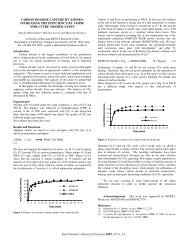
Optimum temperature <strong>of</strong> the high temperature soaking was around 350°C as shown<br />
in klgue 1. However, the CyS (or oil) yield was still low (35%) at 350°C. The two-step<br />
wise soaking was further tested to increase an oil yield. Soaking at 35OoC, followed by<br />
soaking at W C, gave the 50% oil yield (Run 10 in Figure 2), but soaking at 2oo°C,<br />
followed by soaking at 400aC, was not effective and led to the yield <strong>of</strong> more than 100%<br />
482
ecause <strong>of</strong> incorporation <strong>of</strong> the coal liquid used as a solvent (Run 11).<br />
The effect <strong>of</strong> radical initiators on the high-temperature soaking and <strong>liquefaction</strong><br />
were investigated in the recent works7*'. Although it has widely been accepted that radicals<br />
cause retrograde reactions, the addition <strong>of</strong> radical initiators did not have the expected<br />
negative effect and the slightly positive effect in the high-temperature soaking (350-400"C).<br />
The addition <strong>of</strong> H,O, at the high-temperature soaking increased the 5% oil yield under low<br />
pressure hydrogen gas (Run 12)'. The addition <strong>of</strong> small amount <strong>of</strong> water alone gave the<br />
similar change in conversion in the high-temperature soaking. Therefore, a small amount<br />
<strong>of</strong> water or hydrogen peroxide solution may be added to improve the high-temperature<br />
soaking.<br />
The two-step high-temperature soaking at 350°C and 400°C gave the 50% <strong>of</strong><br />
cyclohexane solubles as shown above. This implies that slow heating is better than fast<br />
heating on coal conversion. The autoclave was heated up relatively slowly (at 8°C mid).<br />
The effect <strong>of</strong> heating rate, therefore, was investigated using the microreactor which was<br />
relatively fast heated up in the sand bath. The reactor was heated from room temperature<br />
to 430°C in 0.5 h and held at 430°C for 2 h (Run 13). For Run 14, the mixture was reacted<br />
under the same condition, but heated with a step-wise heating before reaction (at 350°C<br />
for 0.5 h and at 400°C for 0.5 h), and then held at 430°C for 1 h. The total heating-up time<br />
from room temperature to 35WC, from 350°C to 400°C and from 400°C to 430°C was 0.5<br />
h. So, the total residence time including heating-up was 2.5 h. For Run 15, the mixture<br />
was slowly heated from 130°C to 430°C and held at 430°C for 1 h. The total duration <strong>of</strong><br />
heating-up and reaction time was also controlled to 2.5 h. Although the coal was reacted<br />
at 430°C for the longest time for Run 13, coal conversion was the lowest among three<br />
Runs. The oil yield was enhanced about 10% by these programmed heatings. These<br />
results shows that the programmed heating or step-wise high-temperature soaking was<br />
important for coal conversion. Song et aL9 recently reported the effect <strong>of</strong> the temperature-<br />
programmed <strong>liquefaction</strong> <strong>of</strong> low rank <strong>coals</strong>. Montana sub<strong>bituminous</strong> coal was converted<br />
to 5-10% more (THF solubles) by slow heating compared to rapid heating.<br />
Coal f.lctionr and liquefactwn<br />
Another important factor to decrease a gas yield is suggested on the basis <strong>of</strong> the<br />
associated molecular nature <strong>of</strong> coal. Hydrocarbons with lower molecular weight generally<br />
produce more gas by thermal pyrolysis. Hydrocarbons with higher molecular weight will<br />
be decomposed under more severe conditions under which more gas will be produced from<br />
hydrocarbons with lower molecular weight. The associated structural model <strong>of</strong> coal can be<br />
regarded as material with broad molecular weight distribution. Therefore, coal with<br />
different molecular weight should be treated separately, if possible.<br />
A low molecular weight fraction may be separated after dissolution <strong>of</strong> coal, and a<br />
remaining high molecular weight fraction may selectively be liquefied. Here, pyridine<br />
solubles and insolubles were separately liquefied to compare their conversions under the<br />
same condition (Runs 16 and 17). Approximately the same oil yield was obtained from<br />
pyridine solubles and insolubles (Figure 3). Furthermore, cyclohexane insolubles from Run<br />
10 was examined. The 50% oil yield was obtained even from this fraction (Run 18).<br />
The <strong>liquefaction</strong> characteristics <strong>of</strong> @e soluble and insoluble components has recently<br />
483<br />
.
I<br />
been reviewed and studied''. The dissolution and hydrogen consumption rates <strong>of</strong> a pyridine<br />
extracted coal and a whole coal were similar for West Kentucky coal (80% carbon, daf)".<br />
Whereas, a significant decrease in <strong>liquefaction</strong> conversions was observed when a coal was<br />
extracted with pyridine for Illinois no. 6 coal". Waninski and Holder" found the<br />
retrogressive behavior in conversion for pyridine extract part <strong>of</strong> Illinois no. 6 coal.<br />
Although it is difficult to conclude the effect <strong>of</strong> the soluble and insoluble components fmm<br />
these results, it seems that the reactivity <strong>of</strong> residues or high molecular weight components<br />
is not so poor as that <strong>of</strong> low molecular weight components.<br />
The assmiutd molecular nature and liipefactwn<br />
It was shown that a large portion <strong>of</strong> coal can be dissolved by the high-temperature<br />
soaking in the coal liquid, and the programmed or step-wise heating is preferred to enhance<br />
an oil yield. The highly dissolved coal was liquefied to a larger extent. Further, it was<br />
suggested that coal with a broad molecular weight distribution should be separated into an<br />
oil fraction after dissolution, and that only residue should be liquefied at the following step.<br />
From these results, a new concept is proposed to increase an oil yield and decrease a gas<br />
yield as shown in the block diagram (Figure 4). Coal is soaked in a recycle oil at 350°C and<br />
at 400°C. Gas and oil are recovered by vacuum distillation, and the bottom fraction is fed<br />
to a <strong>liquefaction</strong> section and liquefied under low pressure hydrogen at a relatively low<br />
temperature.<br />
The proposed procedure was tested using an autoclave. The DECS-2 coal was<br />
soaked in the coal liquid under nitrogen at 350°C and at 400°C for 1 h, respectively. The<br />
oil fraction was extracted with cyclohexane, and the cyclohexane insoluble portion was<br />
liquefied under low pressure <strong>of</strong> hydrogen (2.8 MPa) at 430°C for 1 h (Run 20). For<br />
comparison, the coal was soaked in the coal liquid at 200°C for 1 h, and then the mixture<br />
was liquefied under the same condition for 2 h (Run 19). In these Runs, gas yields were<br />
analyzed. Figure 5 shows these results. It is notable that the CyS (or oil) yield increased<br />
30% and the gas yield decreased 15%.<br />
DECS-8 (sub<strong>bituminous</strong>) coal was also examined with the same procedure. As the<br />
ionic forces are relatively strong and abundant in low rank <strong>coals</strong>', it is an important step<br />
to weaken the ionic forces before the high-temperature soaking. Although it has been<br />
known that acid washing enhances the conversion <strong>of</strong> low rank the details on acid<br />
washing have not clearly been explained. Here, 2N HCl washin2 was used to weaken the<br />
ionic forces in the coal before the high-temperature soaking. The coal was soaked in the<br />
coal liquid at 35OOC and at 400°C for 1 h, respectively. Cyclohexane insolubles from the<br />
soaked coal was similarly liquefied at 430°C for 1 h (Run 22). As the acid washed coal was<br />
dried, the dried DECS-8 coal was soaked at 200°C for 1 h and then liquefied at 430°C for<br />
2 h for comparison (Run 21). Again, more than 30% increase in the oil yield and 20%<br />
decrease in the gas yield was observed by the procedure (Figure 5).<br />
CONCLUSIONS<br />
An improved coal <strong>liquefaction</strong> concept was reinvestigated for the current two-stage process<br />
on the basis <strong>of</strong> the associated molecular nature <strong>of</strong> coal. Since a significant portion <strong>of</strong> coal<br />
molecules are physically associated as pointed in our recent paper, physical dissolution<br />
484
should be considered more. The step-wise high-temperature soaking was a simple and<br />
effective method for coal dissolution. Larger dissolution made <strong>liquefaction</strong> severity lower.<br />
Broad molecular weight distribution in the associated coal was another important factor.<br />
The selective reaction <strong>of</strong> fractions with high molecular weight which were isolated after the<br />
high-temperature soaking made gas yield lower. Tests with using an autoclave by the<br />
concept shown in Figure 5 enabled to produce 30% more oil and 1520% less gas yields.<br />
It is expected that the procedure will result in great cost down in coal <strong>liquefaction</strong>.<br />
ACKNOWLEDGEMENT<br />
This work was supported by the U.S. Department <strong>of</strong> Energy under Contract DEAC22-<br />
91Pc91041.<br />
REFERENCES<br />
1<br />
2<br />
3<br />
4<br />
5<br />
6<br />
7<br />
8<br />
9<br />
10<br />
11<br />
12<br />
13<br />
14<br />
15<br />
16<br />
Nishioka, M. Fuel 1992,71,941<br />
Nishioka, M., Gebhard, L. and Silbernagel, B. G. Fuel 1991, 70, 341<br />
Gollakota, S. V., Lee, J. M. and Davies, 0. Fuel Roc. Tech. 1989, 22, 205<br />
Wham, R. M. Fuel 1987,66,283<br />
Joseph, J. T. Fuel 1991, 70, 139<br />
Joseph, J. T. Fuel 1991, 70,459<br />
Nishioka, M., Laird, W. and Bendale, P. Fuel submitted<br />
Nishioka, M. and Laird, W. Fuel submitted<br />
Song, C., Schobert, H. H. and Hatcher, P. G. Energv & Fueh 1992, 6, 328<br />
Waninski, R. P. and Holder, G. D. Fuel 1992, 71, 993<br />
Whitehurst, D. D., Farcasiu, M., Mitchell, T. 0. and Dickert, J. J. Jr. Electric Power<br />
Research Institute Report EPRI AF-480, Palo Alto, CA, 1077, pp. 74-7-10<br />
Seth, M. PhD Thesis University <strong>of</strong> California Berkeley, Berkeley, CA, 1980<br />
Schafer, H. N. S. Fuel 1970,49, 197<br />
Mochida, I., Shimohara, T., Korai, Y., Fujitsu, H. and Takeshita, K Fuel 1983, 62,<br />
659<br />
%no, M. A, Solomon, P. R., Kroo, E., Bassilakis, R., Malhotra, R. and McMillen,<br />
D. Am. Chem. Soc. Div. Fuel Chon. Repr. 1990,35(1), 61<br />
Joseph, J. T. and Rorrai, T. R. Fuel 1992, 71, 75<br />
485
c.<br />
F<br />
9<br />
rr<br />
5 Y<br />
b<br />
-<br />
B<br />
c<br />
c<br />
c<br />
X<br />
W<br />
i<br />
20<br />
40<br />
30<br />
10 0 d<br />
0 326 360 376<br />
Temperature (OC)<br />
Figure 1 The effect <strong>of</strong> soaking temperature on extractability (DECS-2 coal, 0.35 MPa Na<br />
1.5h)<br />
1 4 ~ r<br />
Run no.<br />
0 cys I ToS-CyS<br />
TS-ToS El TI<br />
Figure 2 The effect <strong>of</strong> stepwise soaking on extractability for DECS-2 caal under N2<br />
except for Run 12 (Conditions: Run 10; 350"C(lh)/430"C(lh), Run 11;<br />
WC(lh)/430"C(lh); Run 12; 350°C(lh)/4300C(lh) with H,O, (3000 ppm) and H, (1.4<br />
Ma), Run 13; 430°C(2.5h), Run 14; 350"C(O.Sh)/4(#PC(0.5h)/4WC(lh), Run 15; 130°C<br />
to 430°C at 3.5"C mid. followed by 4WC(lh))<br />
486
17 18<br />
Run no.<br />
0 cys I ToS-CyS<br />
TS-ToS TI<br />
Figure 3 Coal fractions and their conversions at 430°C for 1 h with 2.8 MPa <strong>of</strong> H, ((Run<br />
16; DEeS-2/F’S, Run 17; DECS-2/PI, Run 18; Cyclohexane insolubles from Run 10)<br />
I<br />
Flgure 4 Block diagram <strong>of</strong> the proposed coal <strong>liquefaction</strong> concept<br />
487
c1 F<br />
0<br />
z j<br />
3<br />
Y<br />
100<br />
90<br />
80<br />
70<br />
=I<br />
60<br />
I 30<br />
I I I<br />
Run no.<br />
I Gas 0 cys I ToS-CyS<br />
mm0 TS-ToS S TI<br />
Figure 5 Coal conversion by the proposed procedure for DECS-2 coal (Runs 19 and 20)<br />
and DES8 coal (Runs 21 and 22) (Run 19; 200"C(lh)/430"C(2h), Run 20, calculation<br />
from Runs IO and 18, Runs 20 and 21 under the same conditions as Runs 19 and 20, see<br />
the text in detail)<br />
488
INTRODUCTION<br />
Effects <strong>of</strong> Thermal and Solvent Pretreatments<br />
on the Elastic Properties <strong>of</strong> Coal<br />
Yongseung Yun and Eric M. Suuberg<br />
Division <strong>of</strong> Engineering, Brown University<br />
Providence, RI 02912<br />
(Keywords: Elastic property, Dynamic Mechanical Analysis, Pretreatment)<br />
It is now well established that thermal pretreatment in a range <strong>of</strong> temperatures lower than those needed<br />
for pyrolysis can significantly affect the penemability and swellability <strong>of</strong> <strong>coals</strong>. This suggests that<br />
judicious use <strong>of</strong> heat together with effective swelling solvents for coal, can affect mass transport <strong>of</strong><br />
reagents or catalysts into or out <strong>of</strong> the coal, during the early stages <strong>of</strong> <strong>liquefaction</strong>.<br />
The present study is concerned with the effects <strong>of</strong> heatholvent pretreatments on the elastic<br />
constants <strong>of</strong> the coal network structure. This, in turn, tells one about how the non-covalent<br />
interactions in coal are being broken down. Studies <strong>of</strong> the elastic properties <strong>of</strong> coal are nothing new<br />
[e.g. 1-10]. Because <strong>of</strong> the compressibility <strong>of</strong> coal, the application <strong>of</strong> mercury porosimetry to pore<br />
characterization in coal has involved careful corrections, so that the actual pore size dismbution could<br />
be calculated [ 1.1 1,121. However, the limitation caused by compressibility <strong>of</strong> bulk coal structure can<br />
be an advantage in revealing the structural changes during pretreatment processes and in establishing a<br />
suitable elastic model for macromolecular coal structure.<br />
It is known that dynamic mechanical methods are ca. 1000 times more sensitive for detecting<br />
molecular relaxations such as the glass transition temperature, Tg, than are differential scanning<br />
calorimetry (DSC)/differential thermal analysis (DTA) techniques [13]. Weller and Wert [7-101 have<br />
extensively applied the torsion pendulum technique, one <strong>of</strong> the dynamic mechanical methods, for<br />
elucidating the elastic properties <strong>of</strong> coal in the temperature range below 200 'C. They employed square<br />
rods cut from whole coal. Since the relevant temperature range for the structural relaxation by heat is<br />
generally higher than 200OC. we decided to study the thermal structural relaxation at temperatures<br />
higher than 2M°C by employing dynamic hechanical analysis (DMA). This technique involves<br />
constant amplitude oscillation <strong>of</strong> the solid to determine stress-strain properties.<br />
EXPERIMENTAL<br />
A DuPont 982 DMA was employed for mechanical analysis. A detailed description <strong>of</strong> the equipment<br />
has been given elsewhere L13.141. The sample for the DMA was prepared by pressing the as-received<br />
coal powder (-100 mesh) obtained from the Argonne Premium Sample Bank with a press normally<br />
used for making FTIR sample pellets, at 15 kpsi for 6-12 hr, which results in a sample <strong>of</strong> ca. 4 mm<br />
thickness with 12.8 mm diameter.<br />
Slippage <strong>of</strong> the samples from the clamps inside the DMA, especially during oscillation in the high<br />
temperature range (>300"C), was noted to be a main cause for irreproducibility. and special care was<br />
taken to make certain that the sample was tightly clamped. The pelletizing process used here clearly<br />
creates a solid tablet <strong>of</strong> different macroscopic mechanical properties than the original solid. The choice<br />
to work with samples prepared in this way was dictated by a desire to continue to use the Argonne<br />
Premium Coal Samples, that are generally only available in powdered form. The gross macroscopic<br />
489
mechanical properties <strong>of</strong> such pellets, e.g. tensile modulus, will clearly be different from those <strong>of</strong> a<br />
sample prepared, for example, by cutting a chunk from a virgin block <strong>of</strong> coal. In fact, any samples cut<br />
directly from coal could still be subject to naturally occurring heterogeneities in the coal, and thus<br />
mechanical properties are in that case still subject to large variations, depending upon the nature <strong>of</strong> the<br />
tests. This is not important for present purposes, because our goal is not to make use <strong>of</strong> macroscopic<br />
mechanical properties. Rather, we are here only interested in changes on the molecular level that<br />
manifest themselves as -in a particular property.<br />
For purposes <strong>of</strong> comparison, we examined the changes revealed by DMA in the context <strong>of</strong> changes<br />
earlier noted using thermal techniques, such as DSC and solvent swelling techniques. The detailed<br />
procedures for obtaining DSC and solvent swelling results have been reported earlier [15,16].<br />
RESULTS AND DISCUSSION<br />
Raw DMA results are obtained as the frequency <strong>of</strong> oscillation and the damping signal. The frequency<br />
<strong>of</strong> oscillation is directly related to an elastic modulus <strong>of</strong> the sample, whereas the energy needed to<br />
maintain constant amplitude oscillation is a measure <strong>of</strong> damping within the sample [14]. Normally, the<br />
modulus is resolved into storage and loss moduli. The storage modulus corresponds to the perfectly<br />
elastic component whereas the loss modulus represents the perfectly viscous component. The<br />
dimensionless ratio <strong>of</strong> loss/storage components is defined as the damping factor, tan 6.<br />
The tensile storage modulus, in absolute value, is comparable to what might be encountered in<br />
some polymer samples. We caution against placing too much emphasis on this absolute value,<br />
because <strong>of</strong> the issues related to pressing samples from powder. Instead, it is features that are clearly<br />
visible in the tan 6 or loss modulus spectra that are <strong>of</strong> significance. It is the changes in storage<br />
modulus E’ and loss modulus E”, and their ratio, tan 6 = WE/ that convey significant information<br />
about microscopic change in the material being tested. Both EN and tan 6, for example, are used to<br />
reveal glass transitions as maxima in the spectra. Physically, E/ represents the elastic energy storage<br />
capacity <strong>of</strong> the material, whereas E// represents the energy lost as heat due to dissipation. Many other<br />
transitions, in addition to a glass transition, can cause changes in EN. Thus this parameter is a sensitive<br />
indicator <strong>of</strong> a change in the ability <strong>of</strong> molecular segments to move, relative to one another. It is this<br />
property we choose to focus on here. It should be also be emphasized that in a transition, such as a<br />
glass transition, the storage modulus will normally show a slow continuous decline, whereas the loss<br />
modulus (and thus tan 6) will show a distinct peak. This is what makes use <strong>of</strong> this modulus preferable<br />
for detecting transition.<br />
In Figure 1, the first transition is seen near 6OoC, for different samples <strong>of</strong> wet, as-received<br />
Pittsburgh high volatile <strong>bituminous</strong> coal. This transition is normally not visible in DSC, because it is<br />
buried beneath the water evaporation peak. The position <strong>of</strong> this peak is sensitive to the presence <strong>of</strong><br />
moisture, as is seen from Figure. 2. This behavior is typical <strong>of</strong> the effects <strong>of</strong> a “plasticizing agent” in a<br />
polymer. The molecular motions <strong>of</strong> the coal chains are enhanced at low temperatures when water is<br />
present, and internal hydrogen bonding <strong>of</strong> the coal itself is suppressed by the opportunity to hydrogen<br />
bond with a solvent (in this case, water).<br />
The large peak that is revealed by tan 6 above 200OC coincides with a transition shown both by<br />
DSC analysis <strong>of</strong> this coal and by a change in tetrahydr<strong>of</strong>uran (THF) swellability (see Figure 3). This<br />
uansition involves an irreversible relaxation <strong>of</strong> the coal structure [16,17].<br />
Figure 4 illusuates the behavior <strong>of</strong> Upper Freepon medium volatile <strong>bituminous</strong> coal in DMA. The<br />
tensile storage modulus exhibits a continuous decline with temperature, except for two regions <strong>of</strong> more<br />
490
apid decline in modulus. The loss modulus, and thus tan 6, both suggest that there is a low<br />
temperature event, again probably associated with moisture in the coal, at below loO°C. The main<br />
relaxation <strong>of</strong> structure starts to occur from 24OoC, as observed in both tensile storage modulus and tan<br />
6. This observation augments the DSC and solvent swelling results (see Figure 5) for the same coal,<br />
in that Upper Freeport coal showed the characteristics <strong>of</strong> a relaxed coal structure such as increased<br />
swellability in solvents and endothermic peak. In the DSC, the coal exhibited a distinct endothermic<br />
peak centered around 350°C which was started from around 310°C. whereas solvent swellability<br />
increased significantly above 250'C. It is thus confimed by DMA that solvent swelling is a more<br />
sensitive indicator <strong>of</strong> irreversible shuctural relaxation than is DSC.<br />
CONCLUSIONS<br />
Two <strong>bituminous</strong> <strong>coals</strong> were subjected to DMA analysis and the results were compared our earlier<br />
reported DSC and solvent swelling results. Results from different techniques appear to point to the<br />
same basic conclusions with regard to transitions, although there are subtle differences between the<br />
resqlts <strong>of</strong> different techniques. The transition related to coal moisture is more visible in DMA and<br />
solvent swelling techniques than in DSC analysis. DMA confirms that solvent swellability is a more<br />
sensitive index <strong>of</strong> macromolecular changes than is DSC. The importance <strong>of</strong> observations made by<br />
several different techniques in order to discern transitions accurately has been noted. This study<br />
confirms the usefulness <strong>of</strong> applying different techniques simultaneously for this purpose.<br />
We noticed that good reproducibility in DMA depends upon the reproducibility <strong>of</strong> forming pellets,<br />
in our case. A main problem was small cracks generated while the pellet was released from the press.<br />
We are further pursuing rhese problems in order to obtain a better description <strong>of</strong> transitions and elastic<br />
properties <strong>of</strong> coal.<br />
ACKNOWLEDGEMENTS The work reported here was financially supported by the Department<br />
<strong>of</strong> Energy Conmct No. DE-AC22-91PC91027 and grant DE-FG22-90PC90308.<br />
REFERENCES<br />
1. Van Krevelen, D.W. In Coal; Elsevier, New York, 1981; Chapter XX.<br />
2. Hiorns, F.J. Fuel 1953,32, 113.<br />
3. Terry, N.B. Fuel 1958,37, 309.<br />
4. Morgans, W.T.A.; Terry, N.B. Fuel 1958,37,201.<br />
5. Hall, P.J.; Marsh, H.; Thermas, K.M., unpublished results, University <strong>of</strong> Newcastle-Upon-Tyne,<br />
1988.<br />
6. Brenner, D. Prepr. Pap.-Am. Chem. Soc., Div. Fuel Chem.1986, 31fI). 17.<br />
7. Weller, M.; Wen, C. Fuel 1984.63, 891.<br />
8. Wert, C.A.; Weller, M.; Caulfield, D. J. Appl. Phys. 1984,56(9), 2453.<br />
9. Wert, C.A.; Weller, M. J. Appl. Phys. 1982,53(10), 6505.<br />
10. Weller, M; Wert, C. Int. Con$ on Coal Science 1987,65.<br />
11. Toda, Y.; Toyoda, S. Fuel 1972,51, 199.<br />
12. Debelak, K.A.; Schrodt, J.T. Fuel 1979,58,732.<br />
13. Wetton, R.E. Polymer Testing 1984.4, 117.<br />
14. Gill, P.S.; Lear, J.D.; Leckenby, J.N. Polymer Testing 1984.4, 131.<br />
15. Yun, Y.; Suuberg, E.M. Prepr. Pap.-Am. Chem. SOC., Div. Fuel Chem . 1992,37(2 ), 856.<br />
16. Yun, Y.; Suuberg, E.M. Fuel 1993, in press.<br />
17. Yun, Y.; Suuberg, E.M. Energy & Fuels 1992.6, 328.<br />
491
0.a<br />
. .<br />
Temperamure ('C)<br />
Figure 1. Tan 6 DMA spectra obtained from 4 OUinin scans <strong>of</strong> as-received and predried (up to<br />
200OC at 4 OC/min) Pittsburgh No. 8 coal pellet samples. Pellets were. made from -100 mesh<br />
powder aftex pressed at 15 kpsi for the duration as specified in the figure.<br />
Figure 2. Effect <strong>of</strong> sample drying on tensile loss modulus obtained at 4°C/min for Pittsburgh<br />
No. 8 coal. Sample pellets were made from -100 mesh powder pressed at 15 kpsi for 10 hr.<br />
492<br />
t
-0.01-<br />
. 04<br />
5 -0.03-<br />
E<br />
6 -0.0s-<br />
c)<br />
6<br />
Y<br />
0 .- c)<br />
d<br />
.-<br />
-<br />
0)<br />
3.0 -<br />
3 1.5v1<br />
h<br />
12it<br />
Y<br />
m 9-<br />
8<br />
J 6-<br />
m<br />
2<br />
Pyridine<br />
(b) Solvent swelling<br />
1.0- ' 1 ' 8 . I , I .<br />
15<br />
3-<br />
2nd.3rd<br />
1st-2nd<br />
lstdrd<br />
0 100 200 300 400 500<br />
Temperature ("C)<br />
Figure 3. Difference DSC thermograms as well as pr<strong>of</strong>iles <strong>of</strong> solvent swelling ratio and weight<br />
loss obtained at 8 "Umh from -100 mesh Pittsburgh No. 8 coal powder (swelling time:a 5 hr.0,<br />
1 day;., 2 days;A,4 days;o,S days;m,6 days).<br />
493
soL-.--.+-.-.-< : . . . .---+..<br />
40 80 120 IBO 200 210 280 120 ltlo 400 440<br />
Temperature ("C)<br />
0.32-<br />
2 1<br />
'' 3<br />
32n.. 2. I<br />
0.20.. 22 f<br />
0.18. 21<br />
0.12. 20<br />
Figure 4. DMA scan <strong>of</strong> the Upper Freeport medium volatile <strong>bituminous</strong> coal obtained at<br />
4'C/min. Sample pellet was made from -100 mesh powder pressed at 15 kpsi for 12 hr.<br />
01<br />
4.01<br />
4.03<br />
E 4.05<br />
Zmddrd<br />
In-2nd<br />
1sb3rd<br />
1 (a) Difference DSC<br />
4.09 '<br />
1 (b) Solvent swelling<br />
'.O 1 /a<br />
Pyridim , .,I , s<br />
z 4.07<br />
c<br />
(c) Weight loss<br />
0 100 100 300 400 3<br />
Temperature ("C)<br />
494<br />
0<br />
I<br />
Figure 5. Difference DSC thermograms<br />
as well as pr<strong>of</strong>iles <strong>of</strong> solvent swelling<br />
ratio and weight loss obtained at 8'Umin<br />
from -100 mesh Upper Freeport coal<br />
powder (swelling time:0,5 k,O, 7 days).
Assessment <strong>of</strong> Small Particle Iron Oxide Catalyst<br />
for coal Liquefaction<br />
Richard Anderson, Edwin N. Givens and Frank Derbyshire<br />
University <strong>of</strong> Kentucky Center for Applied Energy Research<br />
3572 Iron Works Pike, Lexington, KY 40511-8433<br />
Keywords: Coal <strong>liquefaction</strong>, iron oxide, catalysis<br />
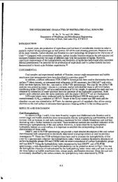
Introduction<br />
Current efforts to lower the cost <strong>of</strong> producing coal liquids are<br />
concentrated on the use <strong>of</strong> low-rank coal feedstocks, and dispersed<br />
catalysts to promote coal dissolution in the first stage <strong>of</strong> a two-stage<br />
process. Molybdenum and iron are the most commonly investigated<br />
catalyst metals, and precursors <strong>of</strong> both can be converted to an active<br />
sulfide catalyst under <strong>liquefaction</strong> conditions.' Although iron<br />
catalysts are less active, they are preferred for reasons <strong>of</strong> economy.<br />
A great deal <strong>of</strong> research has been spent in attempting to understand the<br />
chemistry <strong>of</strong> <strong>liquefaction</strong> in the presence <strong>of</strong> iron catalysts. It has<br />
also been demonstrated that the use <strong>of</strong> powdered iron catalysts has<br />
allowed the <strong>liquefaction</strong> <strong>of</strong> sub<strong>bituminous</strong> <strong>coals</strong> which could not<br />
otherwise be processed'. Nevertheless, the activity <strong>of</strong> these catalysts<br />
is still much less than desired and means to enhance their activity are<br />
under investigation.<br />
The catalyst activity is determined principally by its composition and<br />
the extent <strong>of</strong> its dispersion with the coal or coal-solvent slurry. The<br />
catalyst dispersion is dependent upon the form and mode <strong>of</strong> addition <strong>of</strong><br />
the catalyst precursor. High activities are reportedly favored by<br />
catalysts introduced as oil-soluble organometallic precursors such as<br />
naphthenates and carbonyls. 3s4s The results <strong>of</strong> some studies, however,<br />
indicate that even with these precursors, quite large crystallites or<br />
agglomerates can be formed during <strong>liquefaction</strong> and hence the<br />
potentially high dispersion is not maintained. There is some evidence<br />
to suggest that, if introduced as fine particulates, there is less<br />
tendency for agglomeration. Iron particles <strong>of</strong> about 50 nmmean diameter<br />
synthesized by a flame pyrolysis technique appeared to have retained<br />
their particle size and shape during presulfiding and coal<br />
<strong>liquefaction</strong>.'.' Other work has shown that FeS is more active as a<br />
colloid than in powder form.' A number <strong>of</strong> studies have reported<br />
enhanced catalytic activity by using methods <strong>of</strong> preparation that<br />
introduce nanometer size iron catalysts .9*10J1,12<br />
The work presented in this paper is concerned principally with a<br />
systematic evaluation <strong>of</strong> the effect <strong>of</strong> reaction parameters on the<br />
catalytic conversion <strong>of</strong> a sub<strong>bituminous</strong> coal using a commercially<br />
produced nanometer size iron oxide catalyst. The work is part <strong>of</strong> a DOE<br />
program to evaluate process concepts that can alone, or in concert,<br />
significantly improve process economics. In order to make realistic<br />
assessments, studies have been made using process recycle oil from the<br />
Wilsonville Advanced Coal Liquefaction Research and Development<br />
Facility and Black Thunder sub<strong>bituminous</strong> coal.<br />
Materials<br />
Reasents - Reagents were purchased as follows: Practical grade dimethyl<br />
disulfide (DMDS) from Fluka AG; 99% purity W grade tetralin, high<br />
purity tetrahydr<strong>of</strong>uran (THF), and high purity pentane were Burdick &<br />
Jackson Brand from Baxter S/P; UHP 6000W hydrogen was supplied by Air<br />
Products and Chemicals, Inc. Coal, coal derived liquids and iron oxide<br />
used at the Wilsonville Advanced Coal Liquefaction Research and<br />
Development Facility were supplied by CONSOL, Inc.<br />
495
- Black Thunder sub<strong>bituminous</strong> coal was ground to -200 mesh,<br />
riffled and stored under nitrogen at 4OC in a refrigerator.<br />
Recvcle oil - A reconstituted recycle oil was used in this program that<br />
had been produced at Wilsonville in runs where the plant was in the<br />
distillate production mode with all residual materials being recycled<br />
to extinction except for the organic matter occluded in the ash<br />
reject.13 The Wilsonville recycle oil, taken from Run 262 while<br />
operating on Black Thunder Coal, contained 43.8 wt% 1050°F- distillate,<br />
36.6 wt% residual organic material, 9.2 wt% cresol insolubles and 10.4<br />
wt% ash.<br />
The fractions that were used to form the recycle oil contained<br />
significant concentrations <strong>of</strong> both molybdenum and iron which were being<br />
added as catalysts in Run 262. The ashy resid contained 3.3 wt% iron<br />
plus 300 ppm molybdenum. The distillate contained only 200 ppm <strong>of</strong> iron<br />
and 2 ppm <strong>of</strong> molybdenum. It is assumed that these metals possess some<br />
indeterminate residual catalytic activity. However, in this research,<br />
these effects are integrated into the '@thermal@@ baseline.<br />
Catalysts - Two iron oxide catalyst precursors were used in this study.<br />
One was a sample <strong>of</strong> the iron oxide used at Wilsonville in Run 262 (WIO)<br />
while the other was a sample <strong>of</strong> superfine iron oxide (SFIO) provided<br />
by MACH I, Inc., Xing <strong>of</strong> Prussia, Pennsylvania. The latter has a bulk<br />
density 1126th that <strong>of</strong> the WIO (.052 vs. 1.37 glml), and a very high<br />
surface area (318 vs. 9 m2/g for WIO).<br />
Experimental<br />
Eauioment and Procedures - In a typical experiment 3 grams <strong>of</strong> coal,<br />
5.4 grams <strong>of</strong> recycle oil, catalyst and DMDS (2.4 moles S/mole Fe added<br />
as catalyst) were added to the reactor. The reactor was sealed,<br />
pressurized with hydrogen to 1000 psig, and leak tested. Reactions<br />
were carried out in a fluidized sandbath set at the specified<br />
temperature while the reactor was continuously agitated at a rate <strong>of</strong><br />
400 cycles per minute. At the termination <strong>of</strong> the reaction period, the<br />
reactor was quenched to ambient temperature in a room temperature sand<br />
bath. The gaseous products were collected and analyzed by gas<br />
chromatography. A solvent separation technique, which is described in<br />
detail elsewhere,14 was used to separate both reactants and products.<br />
The solid-liquid products were scraped from the reactor using THF and<br />
the mixture was extracted in a Soxhlet apparatus for 18 hours. The THF<br />
insoluble material, which was comprised <strong>of</strong> IOM and ash, was dried<br />
(80°C/25 mm Hg) and weighed. The THF solubles were concentrated by<br />
removing excess THF in a rotary evaporator to which a 50:l excess<br />
volume <strong>of</strong> pentane was added to precipitate the preasphaltenes and<br />
asphaltenes (PA+A). The mixture was placed in an ultrasonic bath for<br />
3 minutes to facilitate the precipitation process before filtering <strong>of</strong>f<br />
the PA+A. The PA+A fraction was dried and weighed. This then<br />
separates the product into oils, PA+A and IOM plus ash.<br />
Material Balance and Product Yield Comoutational Methods - The<br />
calculation <strong>of</strong> the yield <strong>of</strong> products differs somewhat from those<br />
reported elsewhere, in that the feed is comprised <strong>of</strong> the multiple<br />
individual Wilsonville recycle oil fractions in addition to coal and<br />
catalyst. The product distribution was determined using this same<br />
fractionation scheme assuming complete recovery <strong>of</strong> the ash plus<br />
catalyst. In this method the iron is presumed to convert to pyrrhotite<br />
and the weight <strong>of</strong> catalyst reporting to the ash fraction is calculated<br />
as the corresponding weight <strong>of</strong> Fe,,S. By this method water produced<br />
during <strong>liquefaction</strong> is included in the oils fraction. Experimentally,<br />
complete recovery <strong>of</strong> ash and catalyst was demonstrated. Net product<br />
496
yields are calculated by subtracting the amount <strong>of</strong> material contained<br />
in the feed fractions from the corresponding amounts found in the<br />
product fractions. The total <strong>of</strong> the net products equals the amount <strong>of</strong><br />
maf coal in the feed and reflects the net make (or loss) <strong>of</strong> each <strong>of</strong> the<br />
solubility fractions while coal conversion equals 100 minus the yield<br />
<strong>of</strong> IOM.<br />
Emerimental Desiun - A major portion <strong>of</strong> the research reported here has<br />
been concerned with a detailed investigation <strong>of</strong> the influence <strong>of</strong> the<br />
reaction variables during coal <strong>liquefaction</strong> in the presence <strong>of</strong> added<br />
SFIO. An experimental approach was adopted that would maximize the<br />
amount <strong>of</strong> information gathered in a given series <strong>of</strong> experiments and<br />
provide a data set from which to draw valid comparisons. A full 2'<br />
factorial experimental design was developed following the method<br />
described by Box, Hunter, and Hunter.'' The main effects and<br />
interactions <strong>of</strong> reaction temperature, catalyst concentration, and<br />
sulfur concentration were determined separately for each <strong>of</strong> several<br />
dependent variables including THF conversion, hydrogen consumption,<br />
Co+CO,, hydrocarbon gas, oil and PA+A yields. This technique is<br />
particularly applicable to complex reaction systems, such as coal<br />
<strong>liquefaction</strong>, where the reaction mixture is comprised <strong>of</strong> recycle oil,<br />
which itself is a composite <strong>of</strong> three process materials, coal, catalyst<br />
and hydrogen.<br />
Because <strong>of</strong> the high concentration <strong>of</strong> metals in the recycle oil, iron<br />
oxide concentrations were selected which could have a clearly<br />
discernible effect on coal <strong>liquefaction</strong>, ranging'from 1 to 4 wt% Fe on<br />
as-fed coal. Added sulfur was selected to explore a wide range <strong>of</strong> S/Fe<br />
atomic ratios, with the centerpoint at 2:l. The reaction temperatures<br />
were 390 and 44OoC, centered at 415'C.<br />
Results<br />
ComDarison <strong>of</strong> Heaw Distillate and Recvcle oil - Liquefaction <strong>of</strong> Black<br />
Thunder Coal in Wilsonville heavy 1050'F distillate at 415'12 for 60<br />
minutes gave 95 wt% THF conversion and 35.8 wt% oil yield with the<br />
addition <strong>of</strong> 1.1 wt% iron as WIO and excess DMDS for its conversion to<br />
pyrrhotite (see Table 1). The added iron catalyst had a significant<br />
effect on THF conversion and the yield <strong>of</strong> pentane solubles. Based upon<br />
previous results, distillate would exhibit little reactivity under<br />
these conditions and would not complicate the analysis <strong>of</strong> coal<br />
reactivity . l6<br />
However, coal <strong>liquefaction</strong> in the Wilsonville recycle oil produced THF<br />
conversions which regularly exceeded 100%. In a thermal run, without<br />
any added iron oxide, the THF conversion was in excess <strong>of</strong> loo%, and the<br />
oil yield was in excess <strong>of</strong> the yields observed in the run with<br />
distillate alone. The difference between the two solvents was that the<br />
recycle oil contained ashy material taken from the vacuum flash unit<br />
at Wilsonville and a smaller amount <strong>of</strong> deashed resid taken from the<br />
ROSE-SR deashing unit. The unusually high level <strong>of</strong> THF conversion and<br />
high oil yield indicated that the recycle oil IOM was being converted<br />
to soluble product,<br />
Coal Conversion in Wilsonville recvcle oil - Liquefaction <strong>of</strong> Black<br />
Thunder coal in the Wilsonville recycle oil, without added catalyst,<br />
showed steadily increasing THF conversion, oil and gas make with<br />
increasing reaction time at 41592 (see Table 2). The increases<br />
parallel the changes in yield obtained with added 1.1 wt% iron as w10.<br />
The main effect <strong>of</strong> the catalyst was to produce a higher oil yield after<br />
60 minutes. The results are in agreement with experimental data from<br />
pilot plant runs at Wilsonville, in which the addition <strong>of</strong> sulfided iron<br />
491
oxide caused an appreciable increase in conversion. l7<br />
In both thermal and catalytic cases, the CO and C02 are formed at short<br />
times, and the yields increased only slightly between 15 to 60 minutes.<br />
In comparison, the hydrocarbon gas yield increased from 0.5 to 1.9 Wt%.<br />
Much <strong>of</strong> this increase in hydrocarbon gas yield comes from the<br />
conversion <strong>of</strong> recycle oil.<br />
Influence <strong>of</strong> Nanometer Size Iron Oxide ISFIO) - sulfided iron oxide<br />
particles in the size range 50-80 nm, that were prepared by high<br />
temperature thermal oxidation, have been reported to show high activity<br />
for coal <strong>liquefaction</strong>.6 The catalytic effect has been attributed to<br />
the high surface area and small particle size <strong>of</strong> the pyrrhotite formed<br />
upon sulfiding in the presence <strong>of</strong> coal where the pyrrhotite particles<br />
retain the small particle size <strong>of</strong> the oxide precursor.'8 The SFIO,<br />
whose very high surface area is consistent with nanometer size<br />
particles, may also, upon sulfiding, give rise to small particle, high<br />
surface area <strong>liquefaction</strong> catalysts.<br />
The addition <strong>of</strong> SFIO, at a loading <strong>of</strong> 2.5 wt% iron on maf coal,<br />
produced 11 wt% more oils than in the thermal case (see Table 3). In<br />
addition there were slight increases in THF conversion and yield <strong>of</strong><br />
hydrocarbon gases. These data represent the mid-point <strong>of</strong> the ranges<br />
for each <strong>of</strong> the three variables. The results <strong>of</strong> the comparison<br />
illustrate the potential advantage <strong>of</strong> processing with SFIO catalyst.<br />
1;- The R squared<br />
values for each dependent variable that was selected indicate the<br />
degree <strong>of</strong> fit by the linear model coefficients as shown in Table 4.<br />
Values for the coefficients for each <strong>of</strong> the simple linear models are<br />
summarized in Table 5. The P-value <strong>of</strong> each coefficient is shown in<br />
parentheses.<br />
Of the independent factors, temperature has the strongest overall<br />
effect, as seen by the magnitude <strong>of</strong> the coefficients for THF<br />
conversion, hydrogen consumption, and the yields <strong>of</strong> oil and PA+A; the<br />
oil yield increases and PA+A decreases with increasing temperature.<br />
Increasing the catalyst concentration produces moderate effects on THF<br />
conversion, hydrogen consumption, and enhances the PA+A yield.<br />
However, there is no apparent effect <strong>of</strong> catalyst concentration on oil<br />
yield. It must be stressed that only two levels <strong>of</strong> catalyst<br />
concentration have been examined and the zero concentration case is not<br />
included: as shown in Table 3, the addition <strong>of</strong> catalyst significantly<br />
improves the oil yield over the thermal case. The effects <strong>of</strong> added<br />
sulfur are small, producing a weak negative coefficient with respect<br />
to THF conversion, and a negative coefficient with oil yield.<br />
The average increase in oil yield obtained in the three centerpoint<br />
experiments was 11% over the thermal case. This is consistent with the<br />
increase <strong>of</strong> 10 wt% in oil yield predicted by the Z3 factorial design<br />
experiments and lends confidence to the linear model.<br />
The addition <strong>of</strong> 1.1 wt% added iron as WIO, which was the ratio used in<br />
the Wilsonville plant, gave 5% more oil than in the thermal case, which<br />
agrees closely with the results observed at Wilsonville.17 The linear<br />
model predicts that SFIO at the lower concentration level (1.1 wt% Fe)<br />
will produce 15% higher oil yield than in the thermal case, with a<br />
decrease to the observed 11% gain at the center point due to the effect<br />
<strong>of</strong> added sulfur (see Table 6). However, the experimental check <strong>of</strong> this<br />
predicted outcome gave only 8% more oil than the thermal case. The<br />
catalytic activity <strong>of</strong> the SFIO for both oil formation and coal<br />
498
conversion is greater than the corresponding activity <strong>of</strong> the WIO.<br />
The negative effect <strong>of</strong> sulfur on THF conversion and on oil ield was<br />
unexpected based upon the results <strong>of</strong>' DaS Gupta, et al.,' on the<br />
<strong>liquefaction</strong> <strong>of</strong> an iron deficient Indian coal. They found, through a<br />
non-linear parameter estimation procedure, that adding sulfur up to a<br />
SjFe atomic ratio <strong>of</strong> 8 improved conversion. In this system adding<br />
sulfur at a SfFe atomic ratio between 0.6 to 7.4 was detrimental. This<br />
effect could be related to adverse side reactions caused by the<br />
presence <strong>of</strong> excess sulfur.<br />
The negative interaction between temperature and SFIO concentration for<br />
oil yield indicates that thermal effects begin to dominate catalytic<br />
effects at the higher temperature. Also, in addition to thermal<br />
conversion <strong>of</strong> PA+A, the magnitude <strong>of</strong> the catalyst coefficient for the<br />
PA+A model (4.80 vs. 4.08 for THF conversion) suggests that catalytic<br />
IOM dissolution reports mainly to the PA+A fraction.<br />
References<br />
1. Derbyshire, F. J., Catalysis in Coal Liquefaction, IEACRf08,<br />
London, UK, IEA Coal Research, 1988, 69pp.<br />
2. Tomlinson, G. C., Gray, D., Neuworth, M. 8. and Talib, A.,<br />
Report SAND85-7238, Albuquerque, NM, USA, Sandia National<br />
Laboratories, 105pp.<br />
3. Hawk, C. O., Hiteshue, R. W., Hydrogenation <strong>of</strong> Coal in the<br />
Batch Autoclave. Bulletin 6322 Washington, DC, USA, US Department<br />
<strong>of</strong> the Interior, Bureau <strong>of</strong> Mines, 1965, 42pp.<br />
4. Watanabe, Y., Yamada, O., Fujita, K., Takegami, Y. and Suzuki<br />
T., Fuel, 1984, 63, 752-755.<br />
5. Suzuki, T., Yamada, O., Then, J. H., Ando, T. and Watanabe,<br />
Y., Proceedings - 1985 ICCS, Sydney, NSW, Australia, Pergamon<br />
Press, 1985, pp205-8.<br />
6. Andres, M., Charcosset, H., Chiche, P., Davignon, L., Djega-<br />
Mariadassou, G., Joly, J-P. and Pregermain, S., Fuel, 1983, 62,<br />
69-72.<br />
7. Andres, M., Charcosset, H., Chiche, P., Djega-Mariadassou, G.,<br />
Joly, J-P. and Pregermain, S., Preparation <strong>of</strong> catalysts I11 (Eds.<br />
G. Poncelet and P. Grange), Elsevier, 1983, pp675-682.<br />
8. Nakao, Y., Yokoyama, S., Maekawa, Y. and Kaeriyama, K., Fuel,<br />
1984, 63, 721.<br />
9. Cugini, A. V., Utz, B. R., Krastman, D. and Hickey, R. F., ACS<br />
Div. Fuel Chemistry Preprints, 1991, 36 (l), 91.<br />
10. Hager, G. T., Bi, X-X., Derbyshire, F. J., Eklund, P. C. and<br />
Stencel, J. M., ACS Div. Fuel Chemistry Preprints, 1991, 36 (4),<br />
1900.<br />
11. Pradhan, V. R., Tierney, J. W., Wender, I. and Huffman, G.<br />
P., Energy and Fuels, 1991, 5 (3), 497.<br />
12. Huffman, G. P., Ganguly, B., Taghiei, M., Huggins, F. E. and<br />
Shah, N., ACS Div. Fuel Chemistry Preprints, 1991, 36 (2), 561.<br />
13. Southern Electric International, Inc., Technical Progress<br />
Report, "Run 260 with Black Thunder Mine Sub<strong>bituminous</strong> Coal", DOE<br />
Contract No. DE-AC22-90PC90033 and EPRI Contract No. RP1234-1-2,<br />
Document No. DOEfPC90033-16, January 1992.<br />
14. Derbyshire, F., "Advance Coal Liquefaction Concepts for PETC<br />
Generic Bench-scale Unit', DOEjPCj91040-9, May 1992.<br />
15. Box, G. E. P., Hunter, W. G. and Hunter, J. S., Statistics<br />
for Experimenters, John Wiley and Sons, New York (1978).<br />
16. Anderson, R. R. and Bockrath, B. C., Fuel, 1984, 63, 329.<br />
17. Southern Electric International, Inc., Technical Progress<br />
Report, IIIntegrated Two-Stage Liquefaction <strong>of</strong> Sub<strong>bituminous</strong><br />
Coal", DOE contract No. DE-AC22-82PC50041 and EPRI RP1234-1-2,<br />
499
EPRI AP-5221, Final Report, June 1987, pp 3-7.<br />
18. Djega-Mariadassou, G., Besson, M., Brodzki, D., Charcosset,<br />
H., HUU, T. V. and Varloud, J., Fuel Processing Tech, 1986, 12,<br />
143-145.<br />
19. Das Gupta, R., Mitra, J. R., Dutta, B. K., Sharma, U. N.,<br />
Sinha, A. K. and Mukherjee, D. K., Fuel Proc Tech, 1991, 27, 35.<br />
Table 1. Liquefaction <strong>of</strong> Black Thunder Coal with Wilsonville<br />
oils'<br />
Distillateb Distillate Compositeb Composite<br />
Added Fe, wt$<br />
coal<br />
% Yield, maf<br />
coal<br />
none 1.1 none<br />
1.1<br />
Gases 7.3 7.3 6.9<br />
6.9<br />
Oils 24.9 35.8 48.5 53.8<br />
PA+A 54.5 51.9 52.2 45.3<br />
IOM 13.3 5.0 -7.6<br />
-6.0<br />
THF Conv, wt% 86.7 95.0 107.6 106.0<br />
Run No. 281-1 ' 169-2 139-1/<br />
167-1<br />
142-21<br />
189-1<br />
a. 415' C, 1 hour, 1000 psig H2 cold, 5.4 grams recyc e oil, 3.<br />
grams coal, 2.4 mole sulfur/mole iron.<br />
b. No DMDS added<br />
Table 2. Liquefaction <strong>of</strong> Black Thunder Coal in Wilsonville Recycle<br />
Oil'<br />
No Catalyst Added 1.1 wt% Fe Added<br />
15 min 30 min 60 min 15 min 30 min 60 min<br />
Yields, wt %<br />
HC Gases<br />
0.5 1.1 1.9 1.1 1.6 2.1<br />
co+coz<br />
4.5 5.0 5.0 4.4 4.8 4.8<br />
oils<br />
21.3 36.4 48.5 20.8 36.0 53.8<br />
PA+A<br />
57.6 56.2 52.2 58.1 59.3 45.3<br />
IOM<br />
16.1 1.3 -7.6 15.6 -1.7 -6.0<br />
Coal Conv, wt % 83.9 98.7 107.6 84.4 101.7 106.0<br />
Run Number<br />
148-2 167-2 139-1/ 176-1 169-1 189-1/<br />
167-1<br />
142-2<br />
a. 415O C, 1000 psig H, cold, 5.4 grams recycle oil, 3.0 grams coal,<br />
2.4 mole sulfur/mole Fe<br />
500
Table 3. Effect <strong>of</strong> Superfine Iron OxiUe on Liquefaction'<br />
Thermal SFIO A<br />
Iron, wt % coal None 2.5<br />
Yields, wt% maf coal<br />
HC Gases<br />
co+c02<br />
Oils<br />
PA+A<br />
1.9<br />
5.0<br />
48.5<br />
52.2<br />
2.8 0.9<br />
4.7 -0.3<br />
59.1 10.6<br />
43.3 -8.9<br />
IOM<br />
-7.6<br />
-9.9 -2.3<br />
THF Conversion 107.6 109.9 2.3<br />
Run Number 139-1/167-1 174-2/<br />
190-1/190-3<br />
a. 415'C, 1 hour, 1000 psig hydrogen cold, 5.4 grams recycle oil,<br />
3.0 grams coal, 2.0 mole sulfur/mole iron.<br />
Table 4. Dependent Variables EvaluateU<br />
Effect nnits<br />
THF Conv THF conversion, wt% maf coal<br />
m H, H2 consumption, mg/g maf coal<br />
HC Gas Hydrocarbon gas yield, wt% maf coal<br />
CO+C02 CO and C02 gas yield, wt% ma€ coal<br />
TGas Total gas yield, wt% maf coal<br />
Oils wt% maf coal<br />
PA+A wt% maf coal<br />
501<br />
R BcruareU<br />
0.926<br />
0.973<br />
0.969<br />
0.944<br />
0.961<br />
0.880<br />
0.922
Table 5. Summary <strong>of</strong> Estimated Coefficients'<br />
Inter- Tb Xb<br />
cept Coef f Coef f<br />
(PI<br />
+<br />
THF 107.40 4.54 4.08 -1.72<br />
-1.62<br />
Conv<br />
(. 003) (. 005) (. 097)<br />
mg H2 60.28 9.12 2.66<br />
-1.13<br />
(. 001) (. 014)<br />
( .097)<br />
HC Gas 3.50 1.86<br />
( .001)<br />
(.061)<br />
CO+C02 5.06 0.84<br />
-0.20<br />
( .001)<br />
( .046)<br />
TGas 8.57 2.71<br />
(. 001)<br />
Oils 58.61 13.87<br />
( .001)<br />
-12.03 4.80<br />
( .005) ( .085) L<br />
(. 169)<br />
a. All three way interaction coefficients (TxXxS) are small and set<br />
equal to zero. Coefficient estimates are for coded variables<br />
(-l,O,+l).<br />
b. T = temperature; X = wt% Fe in SFIO on coal; S = wt% sulfur in DMDS<br />
on coal; TxX = two-way interaction <strong>of</strong> temperature with wt% Fe in<br />
SFIO on coal; TxS = two-way interaction <strong>of</strong> temperature with wt%<br />
sulfur in DMDS on coal; XXS = two-way interaction <strong>of</strong> wt% Fe in SFIO<br />
with wt% sulfur in DMDS on coal.<br />
Table 6. Comparison <strong>of</strong> Wilsonville and Superfine Iron Oxide'<br />
Fe, wt % coal<br />
Yields, wt%<br />
maf coal<br />
HC Gases<br />
co+c02<br />
oils<br />
Thermal<br />
None<br />
1.9<br />
5.0<br />
48.5<br />
WIO Predictedb Experimental<br />
SFIO SFIO<br />
1.1 1.1 1.1<br />
2.1 2.6 1.2<br />
4.8 4.9 5.0<br />
53.8 63.7 56.9<br />
PA+A<br />
52.2<br />
45.3 35.1 45.1<br />
IOM<br />
-7.6<br />
-6.0 -6.3 -8.2<br />
THF COnV.<br />
107.6<br />
106.0 106.3 108.2<br />
Run Number 13 -11167-1 14 -21189-1 N/A 272-1<br />
a. 415'C. 1 hour, 1000 psig H2 cold, 5.4 grams Wilsonville recycle<br />
oil, 3.0 grams coal, 2.4 moles sulfurlmole iron.<br />
b. Predicted from model parameters. All curvature detected at the<br />
mid-range conditions is accounted for as resulting from<br />
temperature effects.<br />
502
EFFECT OF A CATALYST ON THE DISSOLUTION OF BLIND CANYON COAL<br />
Robert P. Warzinski<br />
U.S. Department <strong>of</strong> Energy<br />
Pittsburgh Energy Technology Center<br />
Pittsburgh, PA 15236<br />
Keywords: coal <strong>liquefaction</strong>, dispersed catalyst, molybdenum hexacarbonyl<br />
INTRODUCTION<br />
The use <strong>of</strong> catalysts to improve the dissolution and <strong>liquefaction</strong> <strong>of</strong> coal dates back to the<br />
1920s. Reviews in this area have been prepared by Weller (11, Derbyshire (21, and<br />
Anderson (3). Recently, interest has been renewed in using dispersed catalysts in the<br />
early phases <strong>of</strong> coal <strong>liquefaction</strong> to improve the quality <strong>of</strong> the products produced during<br />
the initial dissolution and <strong>liquefaction</strong> <strong>of</strong> coal. To facilitate the study <strong>of</strong> dispersed<br />
catalysts in laboratory-scale investigations, a particular sample <strong>of</strong> 'Blind Canyon coal<br />
(denoted DECS-17) that contains very low levels <strong>of</strong> pyrite (0.04 wt% on a moisture-free<br />
basis) has been made available by the Department <strong>of</strong> Energy through the Penn State Coal<br />
Sample Bank. Thus, complications due to inherent catalytic activity associated with<br />
pyrrhotites which can be formed from coal pyrite are eliminated and interferences to the<br />
characterization <strong>of</strong> the added catalysts due to native iron and sulfur are reduced.<br />
The purpose <strong>of</strong> this paper is to define the effects <strong>of</strong> a molybdenum-containing catalyst<br />
on the initial dissolution and conversion <strong>of</strong> the DECS-17 coal as a function <strong>of</strong><br />
temperature. To eliminate competing andlor complicating influences <strong>of</strong> added solvents,<br />
the <strong>liquefaction</strong> tests were performed in the absence <strong>of</strong> such materials. The catalytic<br />
effects on coal conversion and gas uptake were determined by subtraction <strong>of</strong> thermal<br />
data from the corresponding catalytic results at a given temperature. The results provide<br />
a picture <strong>of</strong> the reactivity <strong>of</strong> the DECS-17 coal and its response to a dispersed<br />
<strong>liquefaction</strong> catalyst.<br />
EXPERIMENTAL<br />
All <strong>of</strong> the experiments were performed with the DECS-17 Blind Canyon coal from the<br />
Penn State Coal Sample Bank. The coal was minus-60 mesh and was riffled prior to use.<br />
The elemental analysis (on a dry basis) provided with the coal was as follows: 76.3%<br />
carbon, 5.8% hydrogen, 1.3% nitrogen, 0.4% sulfur, 6.6% ash, and 9.7% oxygen (by<br />
difference). The moisture content <strong>of</strong> the as-received coal was 3.7%.<br />
The <strong>liquefaction</strong> tests were conducted in 31 6 stainless-steel microautoclaves. The total<br />
internal volume, including connecting tubing, <strong>of</strong> the microautoclave used in most <strong>of</strong> this<br />
work was 49.0 cm3. During the tests, the microautoclave was mounted in a horizontal<br />
position and shaken in an arc motion at approximately 360 cycles per minute in a heated,<br />
fluidized sand bath.<br />
The microautoclave was charged with 3.3 g <strong>of</strong> coal and, if used, 0.008 g <strong>of</strong> molybdenum<br />
hexacarbonyl, Mo(CO),. The Mo(CO), was used as received from Strem Chemical<br />
Company. Purity was given as 98 + YO with moisture being the only major contaminant.<br />
No special procedures were used to mix the Mo(CO), with the coal; the compound was<br />
simply added from a spatula directly to the microautoclave containing the coal sample.<br />
503
In all <strong>of</strong> the tests, an initial charge <strong>of</strong> 1030 psig (7.20 MPa) hydrogen gas containing 3%<br />
hydrogen sulfide was added to the microautoclave after it had been pressure tested and<br />
purged with nitrogen.<br />
A series <strong>of</strong> tests were performed <strong>of</strong> 60 minutes duration at 325°C. 350°C. 375"C, 4OO0C,<br />
and 425°C. A slow heat-up procedure was employed in whichxhe microautoclave was<br />
heated along with the sandbath from room temperature to the desired reaction<br />
temperature. The longest heat-up time was approximately 60 minutes to reach the<br />
highest temperature <strong>of</strong> 425°C. The temperature was monitored by a thermocouple<br />
placed inside the microautoclave. The pressure was monitored by an electronic pressure<br />
transducer connected to the microautoclave by a section <strong>of</strong> 118 inch (3.2 mm) stainless-<br />
steel tubing. Time, temperature, and pressure were recorded at ten-second intervals by<br />
a PC-based data acquisition system.<br />
At the end <strong>of</strong> the 60-minute reaction period, the microautoclave was rapidly cooled in<br />
water. The gaseous contents <strong>of</strong> the microautoclave were then measured by water<br />
displacement and a gas sample was taken. The microautoclave was then opened and the<br />
contents removed with tetrahydr<strong>of</strong>uran (THF). Sonication was used to facilitate cleaning<br />
<strong>of</strong> the microautoclave and dissolution <strong>of</strong> the products.<br />
The reaction products were extracted with THF using pressure filtration. The THF<br />
conversion was calculated by determining the difference in the weight <strong>of</strong> the starting coal<br />
and the insoluble residue. Cyclohexane conversion was similarly determined by adding<br />
the THF-soluble material to cyclohexane and performing another pressure filtration to<br />
recover the cyclohexane-insoluble residue. The THF and cyclohexane residues were dried<br />
at 11 0°C under vacuum to constant weight. The conversions are reported on a dry, ash-<br />
free basis.<br />
RESULTS AND DISCUSSION<br />
To determine the effects <strong>of</strong> a catalyst in coal <strong>liquefaction</strong>, it is useful to perform the<br />
<strong>liquefaction</strong> tests without added solvents or vehicles. Previous work has shown that<br />
fundamental catalyst investigations tend to be confounded if any solvents are present<br />
(1,2). In particular, the use <strong>of</strong> reactive liquids such as tetralin was found to exert a<br />
leveling effect on the influence <strong>of</strong> the catalyst on the initial conversion <strong>of</strong> coal (4). Using<br />
only coal and hydrogen magnifies the effect <strong>of</strong> the added catalyst.<br />
In most solvent-free <strong>liquefaction</strong> work, a benefit is noted for impregnating the catalyst<br />
precursor on the coal over adding it as a powder (1,2). This is usually evident by higher<br />
conversions for the impregnated samples. To make the <strong>liquefaction</strong> tests as simple as<br />
possible, it was desirable to utilize a catalyst precursor that required few, if any, special<br />
preparation procedures to produce an active catalyst during the <strong>liquefaction</strong> test.<br />
Compounds commonly used in coal <strong>liquefaction</strong> research such as ammonium<br />
heptamolybdate, ammonium tetrathiomolybdate, and molybdenum trisulfide only perform<br />
well when special procedures are employed either to disperse or impregnate them onto<br />
the coal or to introduce them as very small particles.<br />
Mo(COIB is not commonly used as a catalyst precursor in coal <strong>liquefaction</strong> research.<br />
While it has been shown to be an effective precursor (5.6). it is not practical for use on<br />
a larger scale. However, certain attributes <strong>of</strong> Mo(CO), make it desirable for fundamental<br />
investigations into catalytic mechanisms relative to coal <strong>liquefaction</strong>. In particular, the<br />
504
inherent volatility <strong>of</strong> Mo(CO), permits it to form an active <strong>liquefaction</strong> catalyst (MoS,) in<br />
the presence <strong>of</strong> sulfur with no special preparation, impregnation, or dispersion techniques<br />
(4,6). The reactions involved in the transformation <strong>of</strong> Mo(CO), to MoS, appear to take<br />
place in the gas phase as the carbonyl sublimes and decomposes. Conversion <strong>of</strong> Mo(CO),<br />
to MoS, has been observed to occur at temperatures as low as 100°C in the presence <strong>of</strong><br />
hydrogen sulfide (7).<br />
Figure 1 shows the effect on the conversion <strong>of</strong> the DECS-17 coal <strong>of</strong> simply adding<br />
Mo(CO), powder along with coal to the microautoclave. These tests were performed at<br />
425°C using a slow heatup to reaction temperature and an initial charge <strong>of</strong> 1030 psig<br />
(7.20 MPa) hydrogen/3% hydrogen sulfide. Duplicate tests were performed with the raw<br />
coal (indicated in Figure 1 at 10 ppml and with 100 ppm added molybdenum. Six<br />
replicate tests were performed at a level <strong>of</strong> 1000 ppm added molybdenum. The bars<br />
associated with the data points in Figure 1 indicate the range <strong>of</strong> values obtained (the<br />
results were identical for the tests with raw coal). Good conversions to both THF and<br />
cyclohexane-soluble products are noted at catalyst concentrations <strong>of</strong> 500 ppm Mo (based<br />
on daf coal) or above. These conversions are similar to those obtained with this coal<br />
when using a hydrogen-donor solvent in conjunction with more conventional catalyst<br />
precursors (8). A pronounced catalytic effect is noted even at molybdenum loadings <strong>of</strong><br />
50 to 100 ppm. There does not appear to be much additional benefit <strong>of</strong> using catalyst<br />
loadings above 1000 ppm.<br />
To determine the effect <strong>of</strong> Mo(CO), on the conversion <strong>of</strong> DECS-17 coal as a function <strong>of</strong><br />
temperature, <strong>liquefaction</strong> tests were performed at 25°C intervals from 325°C to 425°C<br />
in the presence and absence <strong>of</strong> this compound. In the catalytic tests, Mo(CO1, was used<br />
at a level <strong>of</strong> 1000 ppm Mo (based on daf coal). Table I summarizes the number <strong>of</strong><br />
replicate experiments that were performed in each case.<br />
Table 1. Number <strong>of</strong> Duplicate Tests Performed on the DECS-17 Coal.<br />
Reaction Temperature, "C<br />
Number <strong>of</strong> Tests Performed<br />
Thermal Tests Catalytic Tests<br />
325<br />
350<br />
375<br />
400<br />
425 4 6<br />
The conversion data for the thermal and catalytic tests are shown in Figures 2A and 28,<br />
respectively. The symbols represent the average conversion value and the bars<br />
associated with the symbols indicate the range <strong>of</strong> values obtained. No bars imply that<br />
the variability was less than two percentage points <strong>of</strong> conversion (the size <strong>of</strong> the<br />
symbols). The figures reveal that greater variability in conversion values was associated<br />
with specific conditions. For example, the greatest variabilities were associated with<br />
determinations <strong>of</strong> cyclohexane conversion for the catalytic tests. It was also noted that<br />
505<br />
.
the filtration <strong>of</strong> the THF solution from the catalytic test at 375°C was much more difficult<br />
than for the same product at the other temperatures, resulting in greater variability than<br />
for the same determination at the other temperatures.<br />
It is evident from the data in Figure 28 that high conversions <strong>of</strong> the DECS-17 coal are<br />
possible with Mo(CO), in the absence <strong>of</strong> any added solvents or vehicles. The THF and<br />
cyclohexane conversions at 425°C are over 90% and 6O%, respectively. Similar<br />
conversions were previously obtained using Mo(CO), with an Illinois No. 6 coal (6). Both<br />
the thermal and catalytic conversions increase with temperature; however, the influence<br />
<strong>of</strong> the catalyst becomes more apparent at higher temperature.<br />
To better illustrate the effect <strong>of</strong> the catalyst, Figure 3 contains the differences obtained<br />
by subtracting the thermal conversions from the corresponding catalytic conversions.<br />
Little or no catalytic effect is observed at 325°C. Other data, which are not presented<br />
here, show that a catalytic effect is observed at this temperature at longer reaction times.<br />
As the reaction temperature increases, there is a corresponding increase in the additional<br />
amount <strong>of</strong> THF conversion due to the effect <strong>of</strong> the catalyst. The catalytic effect levels<br />
as the maximum total conversion is approached (400°C). The greatest increment to the<br />
catalytic effect on THF conversion occurs between 350°C to 375°C.<br />
A different trend is observed for cyclohexane conversion. In this case, no activity is<br />
observed until the reaction temperature exceeds 375°C. at which point the conversion<br />
attributed to the catalyst suddenly increases. In going to 425"C, a smaller increase is<br />
noted. Figure 2A shows that the thermal conversion to cyclohexane-soluble materials<br />
increases steadily from 325°C to 425°C.<br />
Based on the above data and observations <strong>of</strong> the resulting products, it appears that the<br />
catalyst formed from Mo(CO), plays two separate roles in the <strong>liquefaction</strong> <strong>of</strong> the DECS-<br />
17 coal. First, it facilitates the dissolution <strong>of</strong> the coal to heavy products in a manner that<br />
parallels increases in reaction temperature. Second, it improves the conversion <strong>of</strong> these<br />
products to lighter, cyclohexane-soluble material. The onset <strong>of</strong> catalytic activity occurs<br />
at a higher temperature for the latter role. At present, it is not clear whether the<br />
difference in onset temperatures for the two catalytic functions is due to differences in<br />
activation energies for the catalytic reactions responsible for these two roles, or whether<br />
the catalyst itself changes in activity as the reaction temperature is increased. Further<br />
experiments would be required to differentiate between these effects. One possibility is<br />
that the two roles may be explained on the basis <strong>of</strong> two different chemical functions.<br />
That is, THF conversion is catalytically assisted by prevention <strong>of</strong> retrogressive reactions<br />
while cyclohexane conversion is assisted by catalysis <strong>of</strong> cracking or deoxygenation<br />
reactions.<br />
The conversions noted above are calculated by difference using the weights <strong>of</strong> the<br />
insoluble residues collected and thus do not differentiate between the yields <strong>of</strong> liquid and<br />
gaseous products. Figure 4 shows the average production <strong>of</strong> gaseous products for the<br />
thermal and catalytic tests at the various temperatures. It is apparent that most <strong>of</strong> the<br />
gases produced are the result <strong>of</strong> thermal chemistry. The largest increase in gas<br />
production occurs between 400°C and 425°C. Only the production <strong>of</strong> butane and, to a<br />
lesser degree, propane are influenced by the presence <strong>of</strong> the catalyst. The increased<br />
production <strong>of</strong> these species again points to increased cracking activity, possibly <strong>of</strong><br />
hydroaromatic ring structures.<br />
506
Analysis <strong>of</strong> the quantity and composition <strong>of</strong> the gas released when the microautoclave<br />
was depressurized permitted calculation <strong>of</strong> the amount <strong>of</strong> hydrogen consumed during the<br />
reactions. Figure 5 compares the increment in conversion with the increment in hydrogen<br />
uptake resulting from the addition <strong>of</strong> the catalyst. The trends are similar to those in<br />
Figure 3 and are consistent with two separate roles <strong>of</strong> the catalyst. The catalytic<br />
promotion <strong>of</strong> hydrogen uptake is associated with a regular corresponding increase in THF<br />
conversion. This is not the case for cyclohexane conversion. This indicates that<br />
catalytically promoted hydrogen uptake is insufficient in and <strong>of</strong> itself to produce lighter<br />
or less functional <strong>liquefaction</strong> products. Catalytic influence on cracking or deoxygenation<br />
reactions may require higher temperatures.<br />
The total pressure within the microautoclave was also recorded over time for each test.<br />
These data were converted to estimates <strong>of</strong> the moles <strong>of</strong> gas in the microautoclave using<br />
the ideal gas law and an experimentally derived correlation between measured pressure<br />
and reactor temperature. Figure 6 depicts the effect <strong>of</strong> the catalyst on the rate at which<br />
the amount <strong>of</strong> gas present in the microautoclave changed during the <strong>liquefaction</strong> tests<br />
at the different temperatures. The decreases noted in this figure are primarily due to the<br />
uptake <strong>of</strong> hydrogen. The results are averages <strong>of</strong> at least two sets <strong>of</strong> experiments and<br />
again are determined by subtracting the thermal data from corresponding catalytic data.<br />
The abscissa, time, includes the heat-up period and the one hour reaction time. Little<br />
influence <strong>of</strong> the catalyst on the rate <strong>of</strong> hydrogen uptake is noted at 325°C. A slightly<br />
higher rate is observed at 350°C; however, at even higher temperatures a pronounced<br />
increase in the rate <strong>of</strong> hydrogen uptake is noted. The onset <strong>of</strong> this pronounced catalytic<br />
activity occurs at about 370°C. It also appears that a limit for the catalytic influence on<br />
hydrogen uptake <strong>of</strong> about 0.016 moles is approached at 425°C. This is equivalent to<br />
0.01 1 grams <strong>of</strong> hydrogen per gram <strong>of</strong> coal.<br />
SUMMARY<br />
The preliminary work presented here with the DECS-17 Blind Canyon coal shows the<br />
importance <strong>of</strong> utilizing a catalyst in the dissolution and <strong>liquefaction</strong> <strong>of</strong> this coal. Under<br />
the conditions <strong>of</strong> the tests reported here, the catalyst appears to have dual roles in the<br />
conversion to THF- and cyclohexane-soluble products. The catalyst appears to be active<br />
at 350°C with respect to formation <strong>of</strong> the THF-soluble products; however, no activity is<br />
observed with respect to cyclohexane-soluble products until 400°C.<br />
Overall, the data show that high conversions <strong>of</strong> this coal are possible using only a<br />
dispersed catalyst (no added solvents) and hydrogen. In particular, operation at 400°C<br />
results in high conversion but with much lower gas production than at 425°C. If one is<br />
going to study the effect <strong>of</strong> a catalyst on the initial dissolution <strong>of</strong> this coal, it would be<br />
advisable to operate at temperatures below 400°C. If interest is in the production <strong>of</strong><br />
lighter products, then 400°C or higher should be used.<br />
ACKNOWLEDGMENTS<br />
The author would like to thank Richard Hlasnik and Jerry Foster for performing the<br />
microautoclave work.<br />
507
DISCLAIMER<br />
Reference in this report to any specific product, process, or service is to facilitate<br />
understanding and does not imply its endorsement or favoring by the United States<br />
Department <strong>of</strong> Energy.<br />
1<br />
2.<br />
3.<br />
4.<br />
5.<br />
6.<br />
7.<br />
8.<br />
REFERENCES<br />
Weller, S. W. Proc.. Fourth lnte r IE&I 'onal Conference on C m Uses o f<br />
w e n u m , H.F. Barry and P.C.H. Mitchell, eds., 1982, 179-186.<br />
..<br />
Derbyshire, F. J. mlvsis in Coal L iouefaction: New Directions for Resear& ; IEA<br />
Coal Research: London, 1988.<br />
Anderson, L. L. New T rends in Coal Sc ience, Y. Yijriim, ed.; Kluwer Academic<br />
Publishers: Boston, 1988.<br />
Warzinski, R. P. Proc.. U.S. DOE Direct Liouefaction Contractors' Review Meeting,<br />
September 24-26, 1990, 320-336.<br />
Suzuki, T; Yamada, H; Sears, P. L.; Watanabe, Y. m a v & Fuels 1989, 3, 707-<br />
713.<br />
Warzinski, R. P.; Lee, C.-H.; Holder, G. D. The Journal0 f Suoercritical Fluids 1992,<br />
5 60-71.<br />
Warzinski, R. P. Proc.. U.S. DOE Direct Liouefact ion Contractors' Review Meet ing,<br />
September 22-24, 1992, in press.<br />
Personal communication from Anthony V. Cugini, U.S. Dept. <strong>of</strong> Energy, Pittsburgh<br />
Energy Technology Center, Pittsburgh, Pennsylvania.<br />
0 zot-<br />
100 , , , ,,,,,, , , , , , I ,<br />
0<br />
BO -<br />
P<br />
60 0<br />
-<br />
0<br />
0 t1<br />
- -<br />
0<br />
1<br />
0-<br />
10' 102 10s 1 o4<br />
Mo Concentration, ppm<br />
Figure 1. Effect <strong>of</strong> adding MO(CO)~ on the<br />
conversion <strong>of</strong> DECS-17 coal. ( 0 THF<br />
solubility: 0 cyclohexane solubility. Data<br />
at 10 pprn are for raw coal.)<br />
508<br />
-
$ EO<br />
.- 0<br />
m<br />
L<br />
0<br />
c<br />
0<br />
0<br />
> 40<br />
300 350 400 450<br />
Temperature, 'C<br />
Figure 2A. Conversion results from thermal<br />
<strong>liquefaction</strong> tests. ( 0 THF solubility;<br />
0 cyclohexane solubility)<br />
-<br />
0<br />
0<br />
100<br />
40<br />
20<br />
0-<br />
300 350 400 450<br />
Temperature, 'C<br />
Figure 28. Conversion results from catalytic<br />
<strong>liquefaction</strong> tests. ( 0 THF solubility;<br />
0 cyclohexane solubility)<br />
509
Temperature, OC<br />
Figure 3. Catalytic-thermal conversions.<br />
( 0 THF solubility: 0 cyclohexane solubility)<br />
0.12<br />
0.06<br />
TJ<br />
2 0.04<br />
n<br />
g 0.02<br />
" 0.00<br />
4 s k<br />
~ ..<br />
. -<br />
325OC S5OoC 37J°C 4OO0C 425OC<br />
Figure 4. Average gas production for DECS-17<br />
coal for thermal (T) ond catalytic (C) tests at<br />
different temperatures (shown on abscissa).<br />
c<br />
510
0<br />
0<br />
0<br />
0<br />
0.000 0.005 0.010 0.015 0.020<br />
Catalytic-Thermal H, Uptake, g/g daf coal<br />
Figure 5. The effect <strong>of</strong> a catalyst on conversion<br />
as a function <strong>of</strong> the effect <strong>of</strong> a catalyst on<br />
hydrogen uptake. ( 0 - THF solubility; 0 -<br />
cyclohexane solubility)<br />
0.002<br />
0 - 0 0.000<br />
E. -0,002<br />
c<br />
C -0.004<br />
c<br />
C -0.006<br />
-0.000<br />
g -0,010<br />
-5 -0,012 I- \\<br />
s<br />
0<br />
-0.0141 I I<br />
0 E -0.016<br />
0 20 40 60 80 100 120<br />
Time, rnin.<br />
Figure 6. Effect <strong>of</strong> a catalyst on changes<br />
in gas content as a function <strong>of</strong> time and<br />
temperature. Trends are averages <strong>of</strong><br />
catalytic-thermal data.<br />
511
EQUILIBRIUM ADSORPTION OF MOLYBDATE BY COAL<br />
K.T. Schroeder, B.C. Bockrath, and M.L. Tate.<br />
U.S. Dept. <strong>of</strong> Energy, Pittsburgh Energy Technology Center<br />
P.O. Box 10940, Pittsburgh, PA 15236<br />
&WWX!%: Surface Charge, Catalyst, pH Effects<br />
w: To investigate the effect <strong>of</strong> solution pH on the adsorption<br />
<strong>of</strong> molybdate, two lrrgonne Premium <strong>coals</strong> were equilibrated<br />
With aqueous solutions <strong>of</strong> ammonium heptamolybdate at pH 2 and 4.<br />
The extent <strong>of</strong> molybdate adsorption by the coal was calculated<br />
from the decreased concentration <strong>of</strong> molybdate in solution as<br />
determined by atomic absorption. The time necessary to reach<br />
equilibrium was always less than 24 hours: the majority <strong>of</strong> the<br />
adsorption occurred within the first hour. The Wyodak coal<br />
adsorbed more molybdate with better reproducibility than did the<br />
Illinois No.6 coal. The amount <strong>of</strong> Mo adsorbed by both <strong>coals</strong><br />
increased with a decrease in the pH <strong>of</strong> the solution and with<br />
increased concentrations <strong>of</strong> molybdate. The increased adsorption<br />
under acidic conditions is consistent with increased positive<br />
Sites on the coal surface at the lower pH.<br />
Introduction: Electrokinetic studies <strong>of</strong> coal-water suspensions<br />
demonstrate that the surface charge <strong>of</strong> the coal particle is<br />
dependent upon the pH <strong>of</strong> the solution.' At lower pH values, the<br />
coal surface becomes positively charged due to protonation <strong>of</strong><br />
basic sites. For demineralized <strong>bituminous</strong> <strong>coals</strong>, the surface<br />
usually becomes positively charged below pH 6. Lower rank and<br />
oxidized <strong>coals</strong> have lower isoelectric points: they develop a net<br />
positive charge at lower pH levels.<br />
One would expect that the ability to disperse the negatively<br />
charged catalyst precursors, such as molybdenum anions, would be<br />
affected by the charge on the coal surface. If the coal surface<br />
has a net negative charge, the molybdate anion should tend to<br />
aggregate at the small localized positive regions. Increasing the<br />
number <strong>of</strong> the positively charged regions would be expected to<br />
provide more sites for the precursor to bind. This could lead to<br />
a more evenly dispersed catalyst with a smaller particle size.<br />
Experiments with carbon supports indicate that the mechanisms<br />
<strong>of</strong> dispersion can be related to the carbon surface chemistry.=<br />
When a number <strong>of</strong> carbons were treated with molybdate solutions<br />
at a pH above their isoelectric points, only small amounts<br />
<strong>of</strong> molybdenum were adsorbed. When the same carbons were treated<br />
in the same way at a pH lower than the carbon isoelectric point,<br />
considerably larger amounts <strong>of</strong> molybdenum were adsorbed. The<br />
higher molybdenum adsorption at lower pH was taken as evidence<br />
that the lower solution pH resulted in a more positively charged<br />
carbon particle.<br />
The effect <strong>of</strong> surface charge on the application <strong>of</strong> dispersed<br />
phase catalysts to <strong>coals</strong> has been examined only recently.= Such<br />
effects may be important to the art <strong>of</strong> catalyst impregnation. TO<br />
investigate the effect <strong>of</strong> solution pH on the adsorption <strong>of</strong><br />
molybdate, two Argonne Premium. <strong>coals</strong> were equilibrated with<br />
solutions <strong>of</strong> ammonium heptamolybdate at pH 2 and 4. The results<br />
M.Tate was a participant in the Pr<strong>of</strong>essional Internship<br />
Program administered by the Oak Ridge Associated Univer-<br />
sities, Oak Ridge, Tennessee.<br />
512
<strong>of</strong> these studies indicate that control <strong>of</strong> the pH during catalyst<br />
application may lead to more effective impregnation techniques.<br />
-: TO a 1 g sample <strong>of</strong> coal in a 50-mL pyrex centrifuge<br />
tube was added 40 mL <strong>of</strong> a buffered catalyst solution. The slurry<br />
was mixed for periods from 0.5 to 24 hours at ambient temperature,<br />
then centrifuged. Aliquots (3 mL) were removed for atomic<br />
absorption analysis (AA) and the pH was measured. Mixing was then<br />
resumed. The solution pH remained relatively constant. The<br />
measured pH values over the 3 days <strong>of</strong> equilibration were<br />
1.90&0.06 for the solution with an initial pH <strong>of</strong> 1.8 (20 determinations)<br />
and 4.14k0.05 for the solution with an initial pH <strong>of</strong> 4.1<br />
(24 determinations). The average pH <strong>of</strong> the solutions containing<br />
larger amounts <strong>of</strong> molybdate tended to be slightly higher than<br />
those containing lower concentrations, but the difference was<br />
always less than 0.1 pH unit.<br />
Coals: The Wyodak and Illinois No.6 <strong>coals</strong> were obtained from<br />
the Argonne Premium Coal sample bank'. Vials were tumbled prior<br />
to opening in accord with the Argonne instructions. The <strong>coals</strong><br />
were pre-equilibrated with the same buffers that were used to<br />
prepare the catalyst solutions. Although the purpose <strong>of</strong> the preequilibration<br />
was to adjust the pH <strong>of</strong> the coal surface, it also<br />
removed all <strong>of</strong> the alkali and alkaline earth metal cations Na, K,<br />
Mg, and Ca. However, no iron was removed. It was also noted that<br />
the Illinois 16 coal samples wetted more easily and formed fewer<br />
clumps than did the Wyodak samples.<br />
Catalyst Solutions: Ammonium heptamolybdate tetrahydrate<br />
(Fisher, Certified A.C.S.) was used as received to prepare the<br />
various concentrations <strong>of</strong> molybdate in two buffers listed in<br />
Table 1. Concentrations are expressed in ppm molybdenum. An<br />
additional solution at 6000 ppm formed a white precipitate,<br />
presumed to be MOO,, after a couple <strong>of</strong> days. Because <strong>of</strong> this<br />
instability at higher concentrations, experiments were limited to<br />
solutions containing 3000 ppm or less.<br />
Buffer Solutions: All solutions were prepared using deion-<br />
ized water which had been deaerated by purging with argon for *<br />
least 30 minutes prior to use. An acetate buffer <strong>of</strong> nominal pH 4<br />
was prepared using acetic acid and sodium acetate. This gave a<br />
solution with a measured pH <strong>of</strong> 4.1. Similarly, a sulfate buffer<br />
Of nominal pH 2 was prepared using sulfuric acid and sodium<br />
sulfate. This gave a solution with a measured pH <strong>of</strong> 1.8.<br />
Calculations: The molybdate on the coal was calculated from<br />
the loss <strong>of</strong> molybdate from solution according to the equation<br />
where Mo, is the molybdenum concentration in ppm on the coal,<br />
Mo., is the molybdenum concentration in the solution in ppm,<br />
VO+,~, is the volume <strong>of</strong> solution remaining in mL, and Ww1 is the<br />
weight <strong>of</strong> the coal in grams. It was necessary to take into<br />
account the change in volume <strong>of</strong> the solution with each successive<br />
sample i, because the aliquot size was not negligible in comparison<br />
to the solution volume. The concentration <strong>of</strong> molybdate in<br />
solution was measured by AA as described below.<br />
AA Analysis: Atomic Absorption (AA) analyses were performed<br />
using a Perkin Elmer Model 503 flame atomic absorption spectrophotometer.<br />
Ammonium chloride modifier was added to provide a<br />
final concentration <strong>of</strong> 1% in all determinations. The molybdenum<br />
513
concentration was determined by reference to a linear regression<br />
calibration curve derived from four standard solutions ranging<br />
from 0 to 10 ppm no. Samples which exceeded this range were<br />
diluted as needed to fall within the calibrated range.<br />
The agreement <strong>of</strong> the AA results with the concentrations<br />
determined from the weights <strong>of</strong> molybdate and buffer used in the<br />
Solution preparations is shown in Table 1, The last column <strong>of</strong> the<br />
Table lists the concentration determined by AA and the fifth<br />
column lists the concentration <strong>of</strong> Mo determined gravimetrically<br />
in each <strong>of</strong> the solutions used in this study. The agreement<br />
between the two determinations is very good: the gravimetric<br />
determination is always within two standard deviation units <strong>of</strong><br />
the AA result and is <strong>of</strong>ten within one unit. There may be a small<br />
bias in one <strong>of</strong> the methods since the gravimetric determination is<br />
always lower than the AA determination, but the difference is<br />
considered insignificant for the purpose <strong>of</strong> these experiments.<br />
The standard deviations and relative standard deviations<br />
were derived from a series <strong>of</strong> control samples analyzed over the<br />
several days <strong>of</strong> the experiment. The magnitudes <strong>of</strong> the deviations<br />
are similar to those found for the AA technique itself. For<br />
example, the nominal 600 ppm controls gave a standard deviation<br />
<strong>of</strong> 27 ppm at both pH levels. This compares favorably with the<br />
precision <strong>of</strong> the AA technique <strong>of</strong> 42 ppm as determined in separate<br />
quality assurance experiments. Thus, the solutions themselves<br />
were stable with time and precipitation cannot account for the<br />
loss <strong>of</strong> Mo from solution. A false positive was never obtained for<br />
blank samples which were also analyzed routinely in single blind<br />
experiments.<br />
Results: Aqueous solutions <strong>of</strong> ammonium heptamolybdate containing<br />
up to 3000 ppm molybdenum were allowed to equilibrate with<br />
samples <strong>of</strong> the Argonne Premium Wyodak and Illinois No.6 <strong>coals</strong>.<br />
The loss <strong>of</strong> molybdate from solution was monitored by AA analyses<br />
<strong>of</strong> aliquots <strong>of</strong> the supernatant solution. The results obtained<br />
using the Wyodak coal at a pH <strong>of</strong> 2 are shown in v. Molybdate<br />
was adsorbed quickly and equilibration occurred within the<br />
first 24 hours. At the lowest initial concentration, 60 ppm, the<br />
adsorption <strong>of</strong> Mo was complete: the supernatant solution contained<br />
no detectable Mo after the first hour <strong>of</strong> contact. At 600 ppm, 90%<br />
<strong>of</strong> the Mo was adsorbed resulting in about 2 g <strong>of</strong> molybdenum being<br />
adsorbed per 100 g <strong>of</strong> as-received Wyodak coal. Increasing the<br />
solution concentration by a factor <strong>of</strong> 2.5 to 1500 ppm resulted in<br />
increased adsorption by a factor <strong>of</strong> about 2. A further doubling<br />
to 3000 pprn resulted in an even smaller incremental increase in<br />
adsorption, indicating that the amount <strong>of</strong> molybdate that can be<br />
adsorbed is limited. Inspection <strong>of</strong> the graphs in suggests<br />
that under these conditions the limiting value is in the<br />
neighborhood <strong>of</strong> 5%.<br />
Buffering the solution pH to 4 resulted in less molybdate<br />
adsorption, as can be seen in fiWe 2. Although increasing the<br />
initial Mo concentration from 60 through 600 to 3000 ppm resulted<br />
in increased amounts <strong>of</strong> Mo being adsorbed, the equilibrium values<br />
are noticeably lower at this higher pH. For the case at 3000 ppm,<br />
equilibration at a pH <strong>of</strong> 4 resulted in the coal adsorbing 3.4% <strong>of</strong><br />
its weight in Mo; equilibration at a pH <strong>of</strong> 2 resulted in 4.3%<br />
adsorption by coal. Only at 60 pprn where both solutions were<br />
depleted in Mo was the amount adsorbed the same. Thus, lowering<br />
the PH <strong>of</strong> the medium effects a larger adsorption <strong>of</strong> molybdate<br />
from solution.<br />
514
Different levels <strong>of</strong> adsorption occurred when a <strong>bituminous</strong><br />
coal was used. Similar experiments using the Argonne Illinois<br />
N0.6 coal resulted in the data presented in Bigures 3 fi 4 . In<br />
contrast to the rather smooth trends discernible at all Mo<br />
concentrations for the Wyodak coal, the results for the Illinois<br />
coal contained appreciable scatter at the highest Mo concentra-<br />
tion. Despite this scatter, some comparisons between the Wyodak<br />
and Illinois <strong>coals</strong> can be made by focusing on the results ob-<br />
tained at the 60 and 600 ppm concentrations. At these lower<br />
initial molybdenum concentrations, a rapid equilibration apparent<br />
within the first 24 hours was consistent with the rapid equili-<br />
bration seen for the Wyodak coal. However, the amount <strong>of</strong> MO<br />
adsorbed was much smaller than was seen for the lower rank coal.<br />
At 60 ppm, the molybdenum adsorbed was barely above the detection<br />
limits at a pH <strong>of</strong> 2 and at the detection limits at a pH <strong>of</strong> 4. By<br />
contrast, the Wyodak coal adsorbed all <strong>of</strong> the available Mo under<br />
similar conditions. At an initial Mo concentration <strong>of</strong> 600 ppm,<br />
the amount <strong>of</strong> Mo adsorbed by the Illinois N0.6 coal is only 10%<br />
<strong>of</strong> that adsorbed by the Wyodak coal. Thus, on a weight basis, the<br />
Wyodak coal is 10 times more effective at adsorbing molybdenum<br />
anions than is the Illinois coal at a pH <strong>of</strong> 2. Substituting a pH<br />
4 buffer (-4) for the pH 2 buffer ( a w e 9) effected an<br />
even greater decrease in lo adsorption for the Illinois N0.6 coal<br />
than it did for the Wyodak coal. At the 600 ppm level, the higher<br />
pH resulted in the coal adsorbing only 0.13% <strong>of</strong> its weight in<br />
molybdate instead <strong>of</strong> the 0.51% seen at the lower pH. Thus, the<br />
Illinois No.6 coal adsorbs less MO from solution than does the<br />
Wyodak coal and the amount adsorbed is more sensitive to the pH<br />
<strong>of</strong> the aqueous solution.<br />
DISCUSSION: The results obtained for these two <strong>coals</strong> appear to be<br />
consistent with an adsorption mechanism in which molybdate in<br />
solution is in equilibrium with surface-bound molybdate. The<br />
extent <strong>of</strong> surface adsorption is expected to depend on both the<br />
concentration <strong>of</strong> molybdenum in solution and the number <strong>of</strong> adsorp-<br />
tion sites available on the coal surface. Because the coal<br />
surface develops more net positive charge at the lower pH, more<br />
anion binding sites are expected to become available. Thus, both<br />
increasing molybdate concentration and decreasing pH are expected<br />
to result in more molybdate being removed from solution.<br />
However, the nature <strong>of</strong> the molybdenum species in solution<br />
changes with changes in total concentration <strong>of</strong> molybdenum(V1) and<br />
PH.' For example, at a total Mo(V1) concentration <strong>of</strong> 50 ppm the<br />
predominate species is Mo(0H). at a pH <strong>of</strong> 2, but Moo,'- predomi-<br />
nates at a pH <strong>of</strong> 4. At a total Mo(V1) concentration <strong>of</strong> 2000 ppm<br />
the predominate species is Mo.0,:- at a pH <strong>of</strong> 2, whereas HMo70,,'-<br />
predominates at a pH <strong>of</strong> 4. This rich chemistry provides alternate<br />
explanations to the observed adsorption trends. Each <strong>of</strong> these<br />
species as well as a number <strong>of</strong> other minor species may all adsorb<br />
with different equilibrium constants. Thus, the details <strong>of</strong> the<br />
adsorption mechanism are not clear.<br />
The adsorption sites on the <strong>coals</strong> are effected by the<br />
solution pH. These sites may reside in the organic portion, the<br />
mineral portion, or both portions <strong>of</strong> the coal. Organic functional<br />
groups play an important role in the electrokinetic behavior <strong>of</strong><br />
coal-water suspensions' and the adsorption <strong>of</strong> molybdate by carbon<br />
supports can be related, in part, to the degree <strong>of</strong> surface<br />
oxidation.' Nitrogen heteroatoms, which become positively charged<br />
in acid, may also play an important role. It is interesting to<br />
note that an atomic MO to nitrogen ratio <strong>of</strong> 1 corresponds to a 5<br />
515
,<br />
weight % MO loading on the Wyodak coal. Thus, it is reasonable to<br />
suspect that the extent <strong>of</strong> molybdate adsorption and the pH<br />
dependence are related to the organic heteroatom content. Also,<br />
mineral matter may play an important role in the adsorption. The<br />
protonation <strong>of</strong> alumina hydroxyl groups is responsible for the<br />
Creation <strong>of</strong> adsorption sites for molybdate on catalyst supports.'<br />
The clays or other minerals in the coal could behave in a similar<br />
fashion.<br />
It is <strong>of</strong> interest to compare these results with those<br />
obtained for some other coal samples. Table 2 compares the<br />
results obtained by Abotsi et al.' with the results obtained<br />
here. Since some <strong>of</strong> the experimental procedures are different,<br />
and the <strong>coals</strong> are not identical, the results are not strictly<br />
comparable. The solution concentration used by Abotsi was 4800<br />
ppm whereas our highest concentration was 3000 ppm. However, the<br />
main points are readily discernable. There is a fairly large<br />
difference in the % Mo adsorbed between the <strong>bituminous</strong> and<br />
sub<strong>bituminous</strong> <strong>coals</strong>. This may be due to the higher oxygen content<br />
<strong>of</strong> the latter. However, there are also differences within rank.<br />
The Montana Rosebud sub<strong>bituminous</strong> coal (PSOC 1493) adsorbed about<br />
half as much Mo as did the Wyodak coal. Thus, the nature <strong>of</strong> the<br />
coal is also important to the adsorption mechanism.<br />
CONCLUSIONS: The extent <strong>of</strong> molybdate adsorption by coal is<br />
affected by the nature <strong>of</strong> the coal and the pH and molybdate<br />
concentration <strong>of</strong> the equilibration solution. Lower pH and higher<br />
molybdate concentrations favor molybdate adsorption. Such effects<br />
may be important to the art <strong>of</strong> catalyst impregnation.<br />
ACI-: The authors thank M s. Deborah Hreha and M s.<br />
Jodi Schuster who performed the AA analyses reported in this work<br />
and Jose Solar for many helpful discussions.<br />
DISCLAIMER: Reference in this report to any specific commercial<br />
product, process, or service is to facilitate understanding and<br />
does not necessarily imply its endorsement or favoring by the<br />
U.S. Department <strong>of</strong> Energy.<br />
BmxEKES<br />
1.<br />
- Laskowski, J.S.; Parfitt, G.D. Surfactant Sci. Ser. 1989,<br />
3.2, 279-327.<br />
2. Solar, J.M.: Leon y Leon, C.A.: Osseo-Asare, K. Radovic,<br />
L.R. Carbon 1990, =(2/3), 369-375.<br />
3. Abotsi, G.M.K.; Bota, K.B.: Saha, G. Energy Fuels 1992,<br />
6(6), 779-782.<br />
4. Vorres, K.S. Energy Fuels 1990, 4, 420-426.<br />
5. Cruywagen, J.J.: De Wet, H.F. Polyhedron 1988, 2(7), 547-<br />
556.<br />
6. Spanos, N.; Vordonis, L.; Kordulis, Ch.; Lycourghiotis, A.<br />
J. Catal. 1990, a, 301-314.<br />
516
Nominal<br />
2<br />
Table 1.<br />
Concentration <strong>of</strong> Molybdenum in Buffered Solutions<br />
COAL<br />
SUBBITUMINOUS<br />
0.0116 100.72<br />
600 0.1078 100.37<br />
3000<br />
60<br />
600<br />
I<br />
ca;-<br />
1 Concen-<br />
lated tration<br />
Concen- Measured<br />
tration i by AA<br />
(ppm no) (ppm Mol<br />
66+5<br />
I (58%)<br />
583 I 598526<br />
0.5487 100.20 2960 29685225<br />
(58%)<br />
0 - 0114 100.60 62 6 625<br />
(+8%)<br />
0.1077 101.46 576 584227<br />
1500 0.1325 50.21 1430 15 50+7 1<br />
(25%)<br />
3000 0.5484 100.22 2957 3152+175<br />
I TABLE 2.<br />
Comparison <strong>of</strong> Molybdate Adsorption for Different Coals<br />
)I I<br />
BITUMINOUS<br />
PH % Mo on Coal % MO on Coal<br />
(Ref. 3) (This Work)<br />
2 2.11 4.1<br />
I<br />
4 1.25 3.5<br />
2 0.29 - >0.5<br />
4 0.19 - >0.3<br />
517
YI I -<br />
0<br />
0 IO 10 a0<br />
TIME (Hours)<br />
40 80 80<br />
ml. Adsorption <strong>of</strong> Molybdate from Solution by Wyodak Coal at<br />
a pH <strong>of</strong> 2. 0 Initial solution concentration = 3000 ppm.<br />
v Initial solution concentration = 1500 ppm.<br />
0 Initial solution concentration = 600 ppm.<br />
A Initial solution concentration = 60 ppm.<br />
0 lo 20 30 40 60 60<br />
TIME (Hours)<br />
PIGURg. Adsorption <strong>of</strong> Molybdate from Solution by Wyodak Coal at<br />
a pH <strong>of</strong> 4. Symbols the same as on Figure 1.<br />
518
-<br />
iF<br />
m<br />
1.6<br />
1.4<br />
1.2<br />
-<br />
-<br />
- 1-<br />
0 0.8 -<br />
0 0<br />
-<br />
0 10 20 30 40 so Bo<br />
TIME (Hours)<br />
m. Adsorption <strong>of</strong> Molybdate from Solution by Illinois No.6<br />
coal at a p~ <strong>of</strong> 2. symbols the same as on Figure 1.<br />
0 10 20 so<br />
TIME (Hours)<br />
40 60 eo<br />
FIGURB.. Adsorption <strong>of</strong> Molybdate from Solution by IllinOiFJ N0.6<br />
Coal at a pH <strong>of</strong> 4. Symbols the same as on Figure 1.<br />
519<br />
0
Empirical Evaloation <strong>of</strong> Coal Amnity for Varioos Chemieals<br />
Tetsuo Aids*', Shuhsaku Suzuki', Masayuki Fujii'<br />
Masakuni Yoshihara', Teijiro Yonezawa2<br />
'Department <strong>of</strong> Industrial Chemistry, Faculty <strong>of</strong> Engineering in Kyushu<br />
Kinki University<br />
11-6 Kayanomori, lizuka, Fukuoka 820, JAPAN<br />
'Department <strong>of</strong> Applied Chemistry, Faculty <strong>of</strong> Science and Engineering<br />
Kinki University<br />
341 Kowakae. Higashi-Osaka 577. JAPAN<br />
INTRODUCTION<br />
Coal is a complicated natural product which has several functional groups in its cross-<br />
linked macromolecular structure. Because <strong>of</strong> this fact the diffusion mechanism <strong>of</strong> the<br />
penetrant molecule into the matrix <strong>of</strong> a solid coal is not so simple. It is quite important to<br />
know the affinity between the penetrant molecule and the macromolecular structure <strong>of</strong><br />
coal for the coal scientists who are challenging to develope efficient chemical<br />
transformations <strong>of</strong> coal such as liquifaclion, gasification and etc.. Neverthless the<br />
reliable methodorogy to determine the affinity has not yet been developed. One <strong>of</strong> the<br />
most practical approach to this goal will be to use the solvent swelling behaviours <strong>of</strong><br />
coal. Because as it is mostly true that better solvent makes coal better swelling, the<br />
equiliblium swelling value(Q-value) <strong>of</strong> the penetrant may reasonably reflect its affinity to<br />
the coal. However, there are some problems in this idea. One <strong>of</strong> the most critical<br />
problems will be how to determine the Q-value <strong>of</strong> solvents(chemicals) which used to be<br />
a solid(crysta1) under the measureing condition. Furthermore the steric bulkiness <strong>of</strong> the<br />
penetrant molecule also will provide an aserious error on the net Q-values(lJ.<br />
Some years ago, we revealed the steric requirement <strong>of</strong> coal toward the penetrant<br />
molecule is significantly relaxed in binary solvent system which is composed with normal<br />
solvent such as methanol or DMF and stericcally hindered molecule(ie., triethylamine or<br />
HMPA)(D. The mechanism <strong>of</strong> the relaxation <strong>of</strong> the steric requirement <strong>of</strong> coal is<br />
considered as follows; the preferential peteration <strong>of</strong> the normal solvent into solid coal<br />
makes the coal-solvent gel. Then. the significant expansion <strong>of</strong> the cross-linked network<br />
<strong>of</strong> coal is induced and thus it makes the bulky molecule easy to penetrate. These findings<br />
hinted us to use this swelling system for evaluating the affinity <strong>of</strong> various chemicals<br />
toward coal.<br />
This paper presents the results <strong>of</strong> the studies on the new methodorogy to evaluate the<br />
coal affinity <strong>of</strong> various chemicals.<br />
EXPERIMENTAL<br />
The swelling measurements were carried out as described into previous paper(3J.<br />
Coal, Illinois No.6 coal. used in these studies was from the Ames Laboratory Coal<br />
Library. Prior to use. the coal was ground. sized. dried at I IOOC overnight under<br />
vacuum, and stored under a nitrogen atmosphere. The solvents were distilled by<br />
orginary procedures before use.<br />
This work was supported by the grant from The Japanese Ministry <strong>of</strong> Education,<br />
during 1989-1992.<br />
520
RESULTS AND DISCUSSION<br />
Swelling <strong>of</strong> Illinois No. 6 Coal in Various Solvent<br />
Coal swells in the various solvent with the different manners. Figure 1 shows the<br />
relation between the equiliblium swelling value <strong>of</strong> the solvent which were determined by<br />
our instrument and its electron donor numbedDN). This type <strong>of</strong> data treatment had been<br />
reported by Manec et al.(4J, and they recognized some correletion between them.<br />
Hoever as far as the data shown in this Figure. it seems to be quite difficult to find out<br />
such correlation. As we discussed before(l), one <strong>of</strong> the problems in this figure is that<br />
the Q-values measured always involve thier steric factor, that is, the sterically hindered<br />
solvents are restricted the penetration into the macromolecular structure <strong>of</strong> coal by the<br />
steric requirement, probably due to the cross-linking density. If in this Figure we can<br />
pick up only the solvents which are not sterically bulky and also have relatively high<br />
dielectric constant(>20), the correlation becomes very clear and almost lenear as shown in<br />
Figure 2. It is quite interesting that the dielectric constant <strong>of</strong> the penetrant also seems to<br />
be one <strong>of</strong> the key parameters controlling the coal affinity. This fact may suggest that<br />
there are the significant contribution to the macromolecular cross-linking structure <strong>of</strong> coal<br />
from relatively week bonding interactions such as van der Waals, hydrogen bonding,<br />
charge transfer bonding and IC-R bonding.<br />
Introduction <strong>of</strong> Coal Affinitv Parameter<br />
Although these data shown above suggest the possibility to use the equiliblium<br />
swelling value(Qva1ue) as a convenient scale for evaluating the affinity to the coal. there<br />
seems to be at least two big problems, that is, the first <strong>of</strong> all is how to determine the Q-<br />
value <strong>of</strong> solid chemicals(crysta1) by means <strong>of</strong> the solvent swelling measurement. and the<br />
second <strong>of</strong> all is how to eliminate the steric factor from the observed Q-value.<br />
Table I summerizes the swelling behaviours <strong>of</strong> Illinois No.6 coal in the steric isomers<br />
<strong>of</strong> butylamine. It is obvious that there is a significant steric equirement on their swelling<br />
which is reflected not only on the swelling rate(V-value), but also on the Q-value. Thus,<br />
the Q-value measured in the neat solvent always involves the contribution from the steric<br />
factor. Namely, in order to use the Q-value as a tool for evaluating the coal affinity, we<br />
have to find out the methdorogy to extract the net Q-value from the observed one.<br />
Figure 3 demonstrate the swelling behaviour <strong>of</strong> Illinlois No.6 coal in the binary<br />
mixture <strong>of</strong> the butylamine and methanol. In the case <strong>of</strong> n-butylamine-methanol system,<br />
the observed Q-values have a nice lenear relationship versus the concentration.<br />
Meanwhile in the mixed system <strong>of</strong> more sterically bulkier isomers such as sec- and tert-<br />
amine a kind <strong>of</strong> the synergistic effet were observed. It is particulary interesting that the<br />
values obtained by the extraporation(ditted line on the figure) from the Q-value at the<br />
lower ocnsentration reagion seems to reasonably reflect their own values. We had<br />
revealed this phenomena as the relaxation <strong>of</strong> the steric requirement by the coa-gel<br />
fomation(D. Now. we may be able to define for the extraporated values obtained on the<br />
Figure to be their potential Q-value(Qpt) which used to be hiddn by the steric factor.<br />
If these speculation are correct, we can use this swelling sytem as a general procedure<br />
for evaluating the coal affinity. Namely, as far as the chemicals are soluble in the<br />
solvent (reference solvent). gas, liquid even sold or crystal, the potential Q-value(Qpot)<br />
must be empirically determined by this method. Farthermore, very fortunately, because<br />
<strong>of</strong> the binary solvent system the steric factor in the observed Q-value can be minimized.<br />
Based on these considerations, we propose a new empirical parameter to evaluate the<br />
affinity to the macromolecular structure <strong>of</strong> coal, as the Coal Affinity Parameter(KQ)<br />
which is calculated following equation.<br />
521
In this study we have adopted N,N'-dimethylformamide(DMD as the reference<br />
solvent. The reason is that it has a powerful ability to solve many kinds <strong>of</strong> chemicals<br />
even inorganic compounds and it is also easy to purified.<br />
Table 2 summerizes the tyipical example <strong>of</strong> Coal Affinity ParametedKQ-value)<br />
determined for various chemicals, In these data it is particulary interesting that the f3naphthol(mp<br />
122-123OC), nitrobenzene and maleic anhydride(mp 54-56OC) have higher<br />
%-values than pyridine. These compounds have long been assumed to have reasonably<br />
good affinity to coal, but their relative abilities were never compared.<br />
Figure 5 shows the relation between Coal Affinity Parameter(K value) and the<br />
electoron donor numberfDN). Surprizingly, a good correlation was %served towards<br />
wide range <strong>of</strong> organic compounds, particularly, a solid(crysta1) compound such as<br />
ethylenecarbonate(mp.350C) and a sterically hindered compound such as<br />
hexamethylphosphoramide(HMPA) in which coal used to give very small degree <strong>of</strong> 9<br />
swelling, probably because <strong>of</strong> the steric hindrance. As previously discussed there seems<br />
to be reasonable relationship between coal affinity and enectron donor numbedDN), and<br />
now we can see a similar relation between the Coal Affinity Parameter(Kpa1Ue) and<br />
DN. Although this methodorogy proposed may not be a perfect one to evaluate the<br />
affinity to coal. but as far as the results shown in this Figure and Table 2, we are very<br />
much encouraged to use the KQ-value for the study on the chemical trasformations <strong>of</strong><br />
coal.<br />
It will be also interesting to examine the dependency <strong>of</strong> %-value on the coal rank or<br />
the nature <strong>of</strong> the reference solvent , which are now underway in our laboratory.<br />
AKNOWLEDGEMENTS<br />
This research was supported by the grant from the Japanes Ministry <strong>of</strong><br />
Education(Kagaku Kenkyuhi Hojokin, Juhten Ryouiki Kenkyu) during 1989-1992.<br />
REFERENCES<br />
(1) T. Aida. K. Fuku . M. Fujii, M. Yoshihara, T. Maeshima, T. G. Squires,<br />
Energy & Fuels, 5, 79(1991)<br />
(2) T. Aida. Y. Shimoura, N. Yamawaki. M. Fujii, T.G. Squires, M. Yoshihara.<br />
T. Maeshima, Prepr. Pap.-Am. Chem. SOC., Div. Fuel Chem., 33, %8(19&3)<br />
(3) T. Aida, T.G. Squires, Prepr. Pap.-Am. Chem. Soc., Div. Fuel Chem..<br />
30,95( 1985)<br />
(4) J. Szeliga, A. Marzec, Fuel, 62, 1229(1983)<br />
522
.<br />
.<br />
% . .<br />
9<br />
'HF 0<br />
0<br />
0<br />
*. . 0<br />
.<br />
.<br />
0 10 20 30 40 50 60<br />
Elsctmn Donor NumbcdDN)<br />
Figure I Camlation between @value and Elcctmn Dom NumbedDN)<br />
(Illinois No. 6 Coal: 60100merh: at 2Bc)<br />
Table I Solvent Swelling <strong>of</strong> Illinois No. 6 Coal. in<br />
Butylamines at 20.0 f 0.5 OC<br />
amine vwb @ ?mdCP CSA'<br />
n-butylamine<br />
isobutylamine<br />
1.0<br />
11.9<br />
2.56<br />
2.57<br />
1.54 32.1<br />
32.8<br />
Yec-butylamine<br />
fert-butylamine<br />
5.4<br />
599<br />
2.41<br />
1.96,<br />
1.37<br />
1.48<br />
33.2<br />
34.1<br />
n100-200 US mesh. bV,, = Vn.h/V- V..a, = 3.1 x 10⁻¹<br />
min-'. CMeasured after 10 days' swelling. dDeterminated by<br />
means <strong>of</strong> Ubbelohde viscometer at 20.00 i 0.02 'C. 'Swelling is<br />
still continuing.<br />
* Cross-sectional Areal A' )<br />
523<br />
4:<br />
I<br />
I<br />
I<br />
e. /'<br />
I<br />
I<br />
I' 7<br />
I<br />
bi<br />
;<br />
I<br />
1.5
I ---b rc-BuNH,<br />
0 50 100<br />
MmH-concentration(vol-%)<br />
figure 3 Coal Swelling in Binary mixture<br />
(Illimir No.6C,ul.WIiXhncrh:il(?O'C)<br />
Table 2 q-values <strong>of</strong> various Chemicals<br />
(Illinois No. 6 Coal; MI(X)mesh; at 20°C)<br />
Chemicals OKQ<br />
nitromethane<br />
acetonitrile<br />
n-butyronitnle<br />
ethlenecarbonate<br />
acetone<br />
trimetylphsphate<br />
DMF<br />
nitrobenzene<br />
b-naphthol<br />
maleic anhydride<br />
benzoic acid<br />
524<br />
0.43<br />
0.41<br />
0.52<br />
0.61<br />
0.68<br />
0.88<br />
I .M)<br />
1.08<br />
1.14<br />
1.21<br />
I .62<br />
1.13<br />
1.22<br />
I .30<br />
0.80<br />
0 50 100<br />
DMF(vol%)
1.50<br />
KQ<br />
1.00<br />
0.50<br />
I / '<br />
02<br />
525<br />
I<br />
1 5<br />
I<br />
I<br />
I<br />
I<br />
/<br />
I<br />
I<br />
I<br />
80 I
PROMOTION OF DEUTERIUM INCORPORATION FROM D2 INTO<br />
COAL MODEL COMPOUNDS BY BENZYLIC RADICALS<br />
Robert D. Guthrie<br />
Buchang Shi<br />
Rustem Sharipov<br />
Department <strong>of</strong> Chemistry<br />
University <strong>of</strong> Kentucky.<br />
Lexington, KY 40506<br />
Burtron H. Davis<br />
Kentucky Center for Applied Energy Research<br />
3572 Iron Works Pike, Lexington, KY 40511<br />
Keywords: D2, hydro<strong>liquefaction</strong>, diphenylethane<br />
INTRODUCTION<br />
A large number <strong>of</strong> revealing mechanistic investigations have been<br />
carried out dealing with the thermolysis <strong>of</strong> coal and compounds which<br />
model its structure. Perhaps because <strong>of</strong> experimental difficulties,<br />
much less attention has been given to the reaction with molecular<br />
hydrogen. It seems fair to say that the detailed mechanism by which<br />
molecular hydrogen, separately or in combination with "donor solvents",<br />
is able to effect the reductive simplification <strong>of</strong> coal is not<br />
completely understood. An obvious approach to following the reaction<br />
with Hz is to substitute D The literature contains ample evidence<br />
that deuterium is incorporaxed into reaction products when thermolysis<br />
<strong>of</strong> coal and coal models is carried out under D2 gas.' It has also been<br />
shown that D-labeled substrates, such as tetralin-a,,, transfer D<br />
atoms back to dihydrogen such that HD is produced from H,.'<br />
Similarly it is clear that once incorporated into a molecule <strong>of</strong> organic<br />
substrate, transfer <strong>of</strong> D atoms between molecules is <strong>of</strong>ten fa~ile.~<br />
Several mechanisms can be involved in the scrambling process.<br />
Molecule-induced homolysis and symmetry-allowed, pericyclic mechanisms<br />
have been documented by Brower and Pajak.4 A demonstration <strong>of</strong><br />
radical-promoted exchange was provided by King and Stock' who showed<br />
that the presence <strong>of</strong> species which undergo facile homolysis increases<br />
the rate <strong>of</strong> transfer <strong>of</strong> deuterium between benzylic positions in<br />
different molecules. The mechanisms suggested seem reasonable,<br />
however, most <strong>of</strong> the proposed schemes do not address the question <strong>of</strong><br />
how the initial transfer from H2 occurs.<br />
The facility <strong>of</strong> the scrambling reactions makes the question <strong>of</strong> how the<br />
hydrogen is transferred from Hq gas into the coal structure in the<br />
first place, a particularly difficult one to answer because the initial<br />
landing site <strong>of</strong> the hydrogen atoms is rendered uncertain. Because the<br />
H-H bond is quite strong, this initial step would seem likely to be<br />
a major obstacle to the process <strong>of</strong> interest and slower than subsequent<br />
events. A scheme put forward by Vernon6 proposes hydrogen abstraction<br />
from H2 by benzyl-type radicals. This suggestion was later supported<br />
by Shin.7 Vernon's suggestion is based on the observation that the<br />
cleavage <strong>of</strong> i,Z-diphenylethane, DPE, gives an increased yield <strong>of</strong><br />
benzene when the reaction is carried out under H2. The phenomenon is<br />
more pronounced when the reactions are run in the absence <strong>of</strong> a hydrogen<br />
atom donor (tetralin or 9,lO-dihydrophenanthrene). It is suggested<br />
that benzyl radicals react with dihydrogen, producing toluene and<br />
526
hydrogen atoms. The hydrogen atoms thus generated are responsible for<br />
the hydrogenolysis <strong>of</strong> the DPE to give benzene. In the presence <strong>of</strong><br />
hydrogen donor solvents, the benzyl radicals react to give toluene and<br />
the production <strong>of</strong> H atoms is reduced. The latter part <strong>of</strong> this scheme<br />
seems quite reasonable based on the observed facility <strong>of</strong> reaction<br />
between benzyl radicals and compounds with structures similar to donor<br />
solvents.a Likewise, the reaction <strong>of</strong> hydrogen atoms with the<br />
aromatic ring <strong>of</strong> DPE seems reasonable both on energetic grounds and in<br />
consideration <strong>of</strong> the results <strong>of</strong> Price' who showed that H-atoms<br />
generated in the thermolysis <strong>of</strong> toluene above 500 'C react with toluene<br />
to produce CH and H2 with nearly equal rates. The reaction between<br />
benzyl radicals and H2 seems the most uncertain part <strong>of</strong> the scheme in<br />
that the C-H bond energy <strong>of</strong> toluene is 85 kcal/mole where as that<br />
<strong>of</strong> H-H is 104 kcal/mole." The reaction <strong>of</strong> benzyl radical with<br />
dihydrogen to form toluene and hydrogen atoms is thus likely to have<br />
an activation enthalpy <strong>of</strong> more than 20 kcal/mole. This would seem to<br />
make it an unlikely competitor with various other potential<br />
reactions <strong>of</strong> benzyl radicals which are possible in the system<br />
studied.<br />
An additional uncertainty regarding these reactions, is that most <strong>of</strong><br />
the reported exchange studies using D2 as a source <strong>of</strong> deuterium had<br />
utilized metal reactor vessels. This raised the question <strong>of</strong> whether<br />
the initial process for introduction <strong>of</strong> D atoms into the thermolysis<br />
milieu might be metal catalyzed. Either the walls <strong>of</strong> the reaction<br />
vessel or metal species contained in common reactor vessel sealants are<br />
possible stopover points for D atoms prior to their introduction at the<br />
seminal sites for the scrambling process. If these were involved, the<br />
well-precedented process <strong>of</strong> double bond reduction by metal-bound<br />
deuterium would then be a likely entry route for D atoms. In cases<br />
where <strong>liquefaction</strong> is accomplished by the deliberate addition <strong>of</strong><br />
hydrogenation catalysts, this would be the expected mechanism.'' As<br />
we wished to understand the noncatalyzed reaction and to use it as a<br />
base line for further studies <strong>of</strong> catalytic agents, we designed and<br />
employed a suitable glass reaction vessel.<br />
RESULTS AND DISCUSSION<br />
Using the glass reactor vessel described in the experimental section,<br />
we have carried out the thermolysis <strong>of</strong> 1,2-diphenylethane, DPE, under<br />
2000 psi <strong>of</strong> D gas at 450 OC. DPE disappeared following a first order<br />
rate law as &own in Figure 1. The resultant mixture showed products<br />
reported earlier by Poutsma" for this reaction in the absence <strong>of</strong> D2:<br />
toluene, benzene, ethylbenzene, stilbene, 1,l-diphenylethane,<br />
phenanthrene and diphenylmethane. We also found what appeared to be<br />
diphenylpropane and trace amounts <strong>of</strong> other materials. For comparison,<br />
we carried out the reaction at the same pressure <strong>of</strong> N, and found most<br />
<strong>of</strong> the same products except, as reported by Vernon,b greatly reduced<br />
relative amounts <strong>of</strong> stilbene, benzene and ethylbenzene. These results<br />
are shown in Table I.<br />
Representative GC\MS data on the mixture obtained from the D2 reaction<br />
are shown in Table 11. The data suggest that deuterium introduction<br />
is taking place both at aliphatic positions and in the aromatic rings<br />
(note both benzene-dl and -d are formed.) To assess the relative<br />
amounts <strong>of</strong> aromatic and alisatic substitution, the reaction mixture<br />
was subjected to gas chromatographic separation and the individual<br />
components analyzed by both 'H-NMR and 'H-NMR. Typical results are<br />
shown in Table 111.<br />
Interestingly, as seen in Table 11, the pattern is very similar for<br />
527
deuterium distribution in toluene and DPE at low conversion. Later in<br />
the reaction, the amount <strong>of</strong> deuterium in DPE is significantly greater<br />
than in toluene. surprisingly, despite the fact that hydrogen atoms<br />
must be supplied in order for DPE to be converted to toluene, the<br />
toluene formed at low conversions (in the 8 minute run, ca. 20% <strong>of</strong> the<br />
bibenzyl has been converted to products and about half <strong>of</strong> this is<br />
toluene) contains only about 20% <strong>of</strong> one atom <strong>of</strong> D by GC/MS. This can<br />
only mean that at least 80% <strong>of</strong> the benzyl radicals reacting to give<br />
toluene do so by removing H atoms, presumably from DPE, rather than D<br />
atoms from D2. Moreover, the fact that at short reaction times, there<br />
is already a substantial amount <strong>of</strong> D in the starting DPE, demands that<br />
at least some <strong>of</strong> the D-substituted toluene arises because it is formed<br />
from D-substituted DPE. This strongly Suggests that DPE molecules can<br />
pick up D atoms without first undergoing homolysis.<br />
If this reasoning is correct, it suggests that the most prominent<br />
reaction <strong>of</strong> the R- + D2 + R-D + D- type, is that in which R- = 1,2-<br />
diphenylethyl radical rather than benzyl radical. This is somewhat<br />
surprising in that more highly-substituted radicals are normally viewed<br />
as being more stable and consequently less reactive. On the other<br />
hand, in the equilibration <strong>of</strong> species present during reaction<br />
conditions, the diphenylethyl radical will achieve higher<br />
c~ncentration‘~ which will compensate for its possibly lower<br />
reactivity. Further, results to be described later for a new substrate<br />
suggest that viewing more highly-substituted radicals as less reactive,<br />
may be an oversimplification.<br />
It will be noted that the deuteration pattern for ethylbenzene as seen<br />
in Tables I and 11, is distinctly different from those <strong>of</strong> toluene and<br />
DPE. If, as is generally accepted,‘ ethylbenzene is formed by the<br />
reaction <strong>of</strong> 2-phenylethyl radical with a hydrogen source, the results<br />
suggest that, being a more reactive radical, the 2-phenylethyl radical<br />
is less selective and therefore reacts directly with D to a greater<br />
extent than do the more stable benzylic radicals presenc. Even after<br />
only 10% conversion <strong>of</strong> DPE, about 50% <strong>of</strong> the ethylbenzene molecules<br />
present contain deuterium. A similar situation exists for 1,l-<br />
diphenylethane which is believed to arise from 2,2-diphenylethyl<br />
radical, believed to be formed by rearrangement.” (See Table 11.)<br />
Unfortunately, we have not yet been able to get reliable GC\MS data for<br />
benzene at low conversion because <strong>of</strong> the problem <strong>of</strong> getting it cleanly<br />
separated from solvent on the GC. We are still working on this.<br />
It has been possible to isolate the more abundant products by<br />
preparative GC. We have then determined both ‘€I and ‘H NMR spectra<br />
using DCOpe as an internal standard for both spectra. This has<br />
allowed us to calculate the relative amounts <strong>of</strong> GC\MS-determined D<br />
atoms which are located at aliphatic vs aromatic sites. These data are<br />
shown in Table 111 for toluene, DPE and ethylbenzene. It is<br />
immediately apparent that deuterium is being incorporated at both<br />
aliphatic and aromatic sites. Moreover, the D-atom populations at the<br />
two types <strong>of</strong> location would appear to be similar in magnitude. This<br />
is consistent with a mechanism in which each aliphatic D atom<br />
introduced R + D, + R-D + DO results in D-atom incorporation in<br />
an aromatic ring. More detailed analysis <strong>of</strong> the recovered DPE suggests<br />
that the number <strong>of</strong> aromatic D atoms exceeds the number <strong>of</strong> aliphatic D<br />
atoms by a factor <strong>of</strong> between 1.2 and 1.5 (average = 1.4). This would<br />
suggest that there is some mechanism for D incorporation at aromatic<br />
sites which does not require an aliphatic radical precursor. There are<br />
a variety <strong>of</strong> possibilities, but one <strong>of</strong> the simplest is the displacement<br />
<strong>of</strong> H atoms by D atoms (probably a two Step process such as reactions<br />
4 and 9 in Figure 3). The H atoms thus generated could then react with<br />
528
D to generate more D atoms. It is reasonable to expect that if D<br />
atoms can displace alkyl radicals from the aromatic ring, the same can<br />
happen for H atoms with a five to one statistical advantage. Seeing<br />
that the amount <strong>of</strong> ethylbenzene produced is roughly 10% <strong>of</strong> the total<br />
conversion, it is perhaps reasonable to find a substantial excess Of<br />
D at aromatic sites.<br />
By computer simulation, we have tried to match the product distribution<br />
(including deuterated products) using only the first 8 reactions shown<br />
in Figure 3. These account only for the introduction <strong>of</strong> deuterium<br />
into starting DPE and the formation <strong>of</strong> toluene. We felt if we could<br />
get close to an accommodation <strong>of</strong> the data with this simple scheme, we<br />
could then approach the full set <strong>of</strong> products by elaboration and fine<br />
tuning. It will be noticed that the reaction <strong>of</strong> benzyl radicals with<br />
molecular deuterium (PhCH2- + D, 4 PhCH,D + D-) has been omitted.<br />
The assumption that only the reactions 1 through 8 are involved leads<br />
to the conclusion that the stoichiometry for formation <strong>of</strong> the major<br />
products should be between:<br />
5 PhCH2CH2Ph + 2 D2 + 2 PhCH(D)CH,Ph + D-PhCH2CHZPh + 3 PhCH3 + PhCH2D (a)<br />
and<br />
6 PhCHZCH2Ph + 2 D2 4 3 PhCH( D) CH2Ph + D-PhCH2CH2Ph + 4 PhCH,<br />
Eq (b) represents the limit in which reaction 2 (Figure 3) becomes so<br />
preferred relative to reactions 7 and 8 that all <strong>of</strong> the toluene formed<br />
arises via reaction 2 and thus would containing no D. Eq (a) results<br />
from the limit wherein reactions 5 and 6 become unimportant relative<br />
to reaction 3 thus maximizing the amount <strong>of</strong> PhCHZD produced. If<br />
reactions 5, 6, 7 and 8 all participate equally in consuming the<br />
adduct, then the intermediate stoichiometry <strong>of</strong> eq (c) should be found.<br />
11 PhCH2CH2Ph + 4 D2 -* 5 PhCH(D)CH2Ph + 2 D-PhCH2CH2Ph + 7 PhCH3 + PhCH2D<br />
(C)<br />
Clearly none <strong>of</strong> these options nor any gradation in between can explain<br />
the observed facts. The observed ratio <strong>of</strong> PhCH2D and PhCH3 is not far<br />
from the stoichiometry <strong>of</strong> eq (c) , but the experimentally observed ratio<br />
<strong>of</strong> aromatically deuterated DPE) to aliphatically deuterated DPE is<br />
found experimentally to be rather constant at a value <strong>of</strong> 1.4. The<br />
stoichiometries <strong>of</strong> eqs (a), (b), or (c) demand that the ratio be<br />
between 0.25 and 0.40. Even if a huge isotope effect were assumed<br />
favoring reaction 5 over reaction 6, the maximum possible ratio would<br />
be 1.0.<br />
Reactions 9 and 10 coupled with reaction 4, constitute a kinetic chain<br />
sequence for the introduction <strong>of</strong> aromatic D without producing<br />
aliphatically deuterated DPE. The stoichiometry <strong>of</strong> this sequence,<br />
taken in isolation from the other reactions is simply:<br />
PhCH2CH2Ph + D2 + D-PhCH2CH2Ph + HD (a)<br />
It therefore seems that it should be possible to combine reactions 1<br />
through 10 to approximately match the experimental data by selecting<br />
an appropriate set <strong>of</strong> relative rates. We are working on this<br />
proposition at the present time and preliminary results indicate that<br />
it will be possible to match the distribution <strong>of</strong> the major products.<br />
529
EXPERIMENTAL SECTION<br />
Reaction Procedure. The device shown in Figure 2 (a) consists <strong>of</strong> a<br />
thick glass reaction bulb with a long capillary neck. The reactor is<br />
inverted and several glass beads are added followed by solid reactants<br />
through the end opposite to the capillary. The reactor is sealed at<br />
the constriction Figure 2 (b). The vessel is then suspended in glass<br />
wool in the interior <strong>of</strong> a stainless steel reaction tube having a long<br />
neck to house the capillary section <strong>of</strong> the vessel. The entire<br />
apparatus is evacuated, pressured with Dz gas, closed <strong>of</strong>f and shaken<br />
at the desired temperature in a fluidized sand bath. When the reaction<br />
is complete, carbon disulfide is added and products removed for<br />
analysis using a long syringe needle. In the absence <strong>of</strong> gas generation<br />
within the tube, our observation has been that little or no material<br />
is lost from the interior <strong>of</strong> the bulb. Control experiments in which<br />
a hydrogenation catalyst was deliberately added showed complete<br />
saturation <strong>of</strong> aromatic compounds under the reaction conditions.<br />
REFERENCES<br />
1. a. Skowronski, R. P.; Ratto, I. B.; Goldberg, I. B.; Heredy, L. A.<br />
- Fuel 1984, 63, 440-448. b. Ratto, J. J. ACS Fuel Chem. PreDrints<br />
1979, a, 155. c. Goldberg, I. B.; Crowe, H. R.; Ratto, J. J.;<br />
Skowronski, P. R.; Heredy, L. A. Fuel 1980, 59, 133. d. Noor, N. S.;<br />
Gaines, A. F. Abbott, J. M. Fuel 1986, B, 67-73. e. Kershaw, J. R.;<br />
Barrass, G. Fuel 1977, s, 455.<br />
2. Cronauer, D. c.; McNeil, D. C.: Ruberto, R. G. Fuel 1982, 61,<br />
610-619.<br />
a 3. a. Franz, J. A.; Camaioni, D. M. Fuel 1984, 63, 213-229. b. Franz,<br />
J. A. Fuel 1979, 405-412. c. Aulich, T. R.; Knudson, C. L.;<br />
Hawthorne, S. B. . Chem. SOC. 1988,<br />
sa, 368-379. d. Benjamin, B. M.; Douglas, E. C.; Mesmer, S. u.<br />
1982, 27, 1-5.<br />
4. a. Pajak, J.; Brower, K. R. J. Om. Chem. 1986, 0, 2210-2216. b.<br />
Brower, KR.; Pajak, J. m., 1984, 49, 3970-3973.<br />
5. King, H. H.; Stock, L. M. Fuel 1982, 61, 257-264.<br />
6. Vernon, L. W. Fuel 1980, 59, 102.<br />
7. Shin, S.-C.; Baldwin, R. M.; Miller, R. L. Enerqv and Fuels 1989,<br />
2, 71-76.<br />
0. Bockrath, B.; Bittner, D.; McGrew, J. J. Am. Chem. SOC. 1984, 106,<br />
135-138.<br />
9. Price, S. J. 1962, 1310.<br />
lo. Benson, S. W. J. Chem. Ed. 1965, u, 502.<br />
11. a. Chien, P.-L.; Sellers, G. M.; Weller, S. W. Fuel Processin<br />
Technoloay 1983, Z, 1-9. b. Brammer, S. T.; Weller, S. W. u. 1979:<br />
2, 155-159. c. Patxer, J. F.; Farrauto, R. J.; Montagna, A. A. Ind.<br />
Fna. chem. Process Des. Dev. 1979, u, 625-630. d. Davis, K. P.;<br />
Garnett, J. L. J. Phvs. Chem. 1971, 22, 1175-1177. e. Davis, K. P.;<br />
Farnett, 3. L.; O'Xeefe, J. H. Chem. Communications 1970, 1672-1673.<br />
530
12. a. Poutsma, M. L.; Dyer, C. W. 3. Ora. Chem. 1982, 42, 4903. b.<br />
Buchanan, A. C.; Dunstan, T. S. J.; Douglas, E. C.; Poutsma, M. L. L<br />
Am. Chem. SOC. 1986, m, 7703.<br />
13. Livingston, R.; Zeldes, H. ; Conradi, M.<br />
101, 4312-4319.<br />
s. -L 1979,<br />
Table I. Product Distribution in the Thermolysis <strong>of</strong> Diphenylethane at<br />
450' C for 30 Minutes<br />
Mole %<br />
Under D,<br />
1,2-Diphenylethane 23.5<br />
Toluene 47.8<br />
1,2,3,4-Triphenylbutane 0.25<br />
Benzene 17.2<br />
Ethylbenzene 8.6<br />
1,l-Diphenylethane 1.5<br />
Stilbene 1.3<br />
Phenanthrene 0.8<br />
Triphenylpropane 0.8<br />
Diphenylpropane 0.44<br />
Diphenylmethane 0.36<br />
Wt. %<br />
Under Dz<br />
36.6<br />
37.1<br />
0.8<br />
9.3<br />
7.7<br />
2.3<br />
1.9<br />
1.2<br />
1.8<br />
0.73<br />
0.52<br />
Mole %<br />
Under N2<br />
36.1<br />
47.1<br />
3<br />
Table 111. Aliphatic vs. Aromatic Deuterium in Products from<br />
Thermolysis <strong>of</strong> 1,2-Diphenylethane under Dz at 450' C by NMR:<br />
Compound Time Aromatic D<br />
(min) /molecule<br />
1,a-Diphenyl-<br />
ethane 8 0.13<br />
30 0.91<br />
Toluene 8 0.17<br />
30 0.65<br />
Benzene 30 0.66<br />
Ethylbenzene 15 0.36<br />
30 0.50<br />
45 1.32<br />
Figure 1. Fiml.Ordw Pi01 for Convenion <strong>of</strong><br />
12-Diphenylethene Under D, a1 450. C.<br />
1.6<br />
1.4 - 0 -<br />
1.2 -<br />
1.0 -<br />
0.1 -<br />
0.11 - .<br />
0.4 -<br />
0<br />
0.2 - E<br />
@<br />
0.0<br />
0 10 20 30 40<br />
Time (min)<br />
50<br />
532<br />
Aliphatic D<br />
/molecule<br />
CH2 CH3<br />
0.09<br />
0.65<br />
0.18<br />
0.39<br />
0.18 0.54<br />
0.213 0.44<br />
0.54 0.71<br />
Figure 2. Glans Readon Vessel for<br />
Thermolysis Under D,.
Figure 3. Minimum Steps to Explin Deuterium DiotribuUon Patlorn<br />
533
COAL LIQUEFACTION USING DONOR SOLVENTS HYDROGENATED AT LOW<br />
TEMPERATURES*<br />
R.J. Kottenstette and H.P. Stephens<br />
Process Research Department 62 12<br />
Sandia National Laboratories<br />
P.O. Box 5800<br />
Albuquerque, NM 87185<br />
Keywords: Hyrogen Donor, Coal Liquefaction, Solvent Quality<br />
Introduction<br />
Direct coal <strong>liquefaction</strong> proceeds initially through a complex series <strong>of</strong> bond breaking and hydrogen<br />
transfer reactions involving coal and a donor solvent. When the recycle solvent contains high<br />
amounts <strong>of</strong> donor solvent, the requirement for high hydrogen gas pressure in the initial stage <strong>of</strong><br />
<strong>liquefaction</strong> is reduced and coal conversion is augmented. Effective tests for hydrogen donating<br />
ability <strong>of</strong> coal derived solvents <strong>of</strong>ten consist <strong>of</strong> GCMS, proton NMR, catalytic dehydrogenation, as<br />
well as microautoclave coal <strong>liquefaction</strong> testing [ 1,2,3]. Microautoclave testing is an empirical<br />
measure <strong>of</strong> solvent quality for hydrogen donation using coal, a donor solvent and an inert gas instead<br />
<strong>of</strong> hydrogen. Previous studies [4] have investigated the hydrogen transfer cycle for direct<br />
<strong>liquefaction</strong> using Illinois #6 high volatile <strong>bituminous</strong> coal and a distillate (650"F-770°F) derived from<br />
a coal <strong>liquefaction</strong> process solvent . The objective <strong>of</strong> this work is to determine the effects <strong>of</strong> donor<br />
solvent on coal conversions in microautoclave <strong>liquefaction</strong> experiments performed at 4OOOC with<br />
Wyodak coal. These tests used a heavy distillate solvent that had been hydrogenated with a synthesis<br />
gas (SO% carbon monoxide:SO% hydrogen) mixture and steam at low temperatures (3OO0C-325"C).<br />
The in situ water-gas shift (WGS) reaction provides an alternate source <strong>of</strong> hydrogen and has the<br />
potential <strong>of</strong> eliminating the need for high purity high pressure hydrogen for solvent hydrogenation.<br />
Hydrogenation at low temperatures can lead to increased donor content since larger amounts <strong>of</strong><br />
hydroaromatics are produced at equilibrium with any given hydrogen pressure. Distillate solvents<br />
were hydrogenated at various weight hourly space velocities, using two different catalysts,and used in<br />
microautoclave coal <strong>liquefaction</strong> tests to evaluate solvent pretreatment effects on coal solubility.<br />
Experimental<br />
Materials - Because solvent quality is favorably affected by increasing the aromatic nature <strong>of</strong> the<br />
solvent being fed to the catalytic hydrotreater, and solvent dewaxing has been shown to be an<br />
effective means <strong>of</strong> increasing the aromatic nature <strong>of</strong> the solvent IS], a heavy distillate and a dewaxed<br />
heavy distillate were used. Heavy distillate sample (V1074) from the Wilsonville, Alabama Advanced<br />
Integrated Two Stage Liquefaction Facility was provided by CONSOL Inc., Library PA. Dewaxed<br />
VI074 distillate was prepared by CONSOL at - 5T from the VI074 heavy distillate using an acetone<br />
dewaxing procedure. 1,2,3,6,7,8 hexahydropyrene was purchased from Aldrich Chemical Company<br />
with a 99% purity. Reagent grade tetrahydrohran (THF), pentane, and heptane were purchased from<br />
Fischer Scientific. Wyodak sub<strong>bituminous</strong> coal was used as -100 mesh from the Argonne Premium<br />
Coal Sample Bank. The NiMo catalyst, was Shell 324M and the platinum catalyst was a hydrous<br />
titanium oxide (HTO) compound synthesized in our lab. Hydrogen, carbon monoxide, and nitrogen<br />
were UHP grade.<br />
*This work was supported by the U. S. Department <strong>of</strong> Energy at Sandia National Laboratories under<br />
contract DE-AC04-76DP00789.<br />
534
Apoaratus and Procedure<br />
Micr<strong>of</strong>low Reactor Experiments - A fixed bed micr<strong>of</strong>low reactor consisting <strong>of</strong> liquid and gas feed<br />
systems and a stainless steel reactor containing the catalyst bed (0.5" O.D.) was used to hydrogenate<br />
heavy distillate and dewaxed heavy distillate. The reactor had an internal volume <strong>of</strong> 23 cm3 and<br />
typically held a 20 gram catalyst'charge. These distillate pretreatment experiments consisted <strong>of</strong> three<br />
days <strong>of</strong> testing for each catalyst and feed combination. The first two days <strong>of</strong> experiments used the in<br />
situ water-gas shift reaction to hydrotreat the distillate. Reactions on the third day used solely<br />
hydrogen to test the effect <strong>of</strong> varying the partial pressure <strong>of</strong> hydrogen gas upon solvent hydrogen<br />
uptake. The reactor tube was first packed with catalyst and then presulfided with a 9% H2S in<br />
hydrogen mixture for four hours at 39OOC for the commercial nickel molybdenum on alumina catalyst<br />
(NIMo), or prereduced in hydrogen at 2OOOC for the platinum (Pt HTO) catalyst. After catalyst<br />
pretreatment, the reactor was pressurized to 1000 psig with a 5050 mixture <strong>of</strong> carbon monoxide and<br />
hydrogen. The reactor temperature was increased to the operating value while the distillate and a<br />
1: 1:l molar mixture <strong>of</strong> CO:H2:H20 was fed the top <strong>of</strong> the reactor. Distillate was pumped into the<br />
reactor with an Eldex A-30 liquid chromatograph pump and the synthesis gas was metered into the<br />
reactor with two Brooks 5850 mass flow controllers. The liquid weight hourly space velocities were<br />
varied between 0.4 hrl and 0.8 hr-1. Water was fed to the reactor with a Beckman 114M micr<strong>of</strong>low<br />
liquid chromatography pump. All reactants flowed downward over the packed bed into a reservoir to<br />
separate the gases and liquids. Solvent and gas products were<br />
taken from the sample reservoir at the bottom <strong>of</strong> the reactor during operation. Reactor pressure was<br />
maintained with a Circle Seal BPRz7A back pressure regulator, which was located downstream from<br />
the liquid separator. Distillates and hydrotreated distillates were also analyzed by high resolution gas<br />
chromatography using a Hewlett Packard 5890 GC to qualitatively measure hydrogenation <strong>of</strong><br />
aromatic compounds.<br />
Microautoclave Experiments - Coal <strong>liquefaction</strong> tests were used to evaluate donor solvent quality.<br />
Hydrogenated solvent was tested in a microautoclave consisting <strong>of</strong> a 0.75" O.D. Swagelok tubing tee<br />
with 40 cm3 <strong>of</strong> gas volume. Pressure and temperature were measured in the micr<strong>of</strong>low and batch<br />
microautoclave reactors with Entran pressure transducers and internal reactor thermocouples. Data<br />
acqusition for both the flow and batch reactor systems was accomplished with a personal computer<br />
using Labtech Notebook s<strong>of</strong>tware.<br />
Coal and pretreated solvents representing various hydroprocessing conditions were weighed into the<br />
microautoclave reactor. The microautoclaves were sealed and pressurized with nitrogen to 100 psig<br />
cold charge to facilitate post reaction gas analysis. The pressurized microautoclaves were then<br />
fastened to a wrist-action shaker and immersed in a fluidized sand bath while being shaken at 200<br />
cycles per minute. After a rapid heat up (< 2min.) the microautoclaves were maintained at 4OOOC for<br />
30 minutes. Following reaction the microautoclaves were cooled to room temperature in water, then<br />
depressurized into gas sample bottles and dismantled to recover the reaction products. The gas<br />
samples were analyzed for hydrogen, carbon monoxide, carbon dioxide and c1-C~ hydrocarbons<br />
using a Carle series 400 Gas Chromatograph. Liquid and solids were recovered from the reactor with<br />
THF and the THF insolubles were determined by pressure filtration. The THF insolubles were dried<br />
and weighed while the THF solubles were rotoevaporated to remove most <strong>of</strong> the THF. Pentane was<br />
then added to these samples to precipitate the preasphaltendasphaltene material. These solutions<br />
were pressure filtered to remove the pentane insolubles. The pentane insolubles were then dried and<br />
weighed.<br />
535
All microautoclave tests were performed with a solvent to coal ratio <strong>of</strong> 1.5: 1 . Solvent samples<br />
&B,C and D, shown in Table 1, were produced in the micr<strong>of</strong>low reactor using various catalysts,<br />
temperatures and weight hourly space velocities (WHSV). Hydrogen donor (H6PY) was added to<br />
comprise 20 % <strong>of</strong> the solvent charge for experiments that were designed to test the effect <strong>of</strong> adding a<br />
known amount <strong>of</strong> a good hydrogen donor. Donor hydrogen was effectively increased in this<br />
"composite" solvent by 0.6 wt% (see Table 1).<br />
Model Compound Test - In a series <strong>of</strong>donor solvent tests which examined the effects <strong>of</strong>using<br />
different levels <strong>of</strong> hexahydropyrene (H6PY) alone as the solvent, heptane was used instead <strong>of</strong><br />
pentane as the precipitating solvent, as shown in Figure 5.<br />
Results and Discussion<br />
The extent <strong>of</strong> distillate hydrogenation is given in Table 1, which shows elemental analysis results for<br />
baseline distillates and hydrotreated products from the micr<strong>of</strong>low reactor. A comparison <strong>of</strong> samples<br />
A and B (from the same reactor run) shows that sample B was hydrogenated to a greater extent than<br />
sample A which had a slower space velocity. This is due in part to catalyst deactivation since sample<br />
B was obtained earlier in the run when the catalyst bed was fresher. The hydrogenated dewaxed<br />
distillates labeled samples C and D compare solvents hydrogenated with different catalysts. The<br />
maximum amount <strong>of</strong> hydrogen increase was 1.0 wt% in the dewaxed distillate (sample D); this<br />
distillate was produced at 325'C.with the Pt HTO catalyst using only hydrogen gas. This catalyst<br />
deactivated to a lesser degree than the NiMo catalyst and was more effective using hydrogen only<br />
rather than the in situ water-gas shift reaction. It is believed that the more aromatic dewaxed solvent<br />
could be hydrogenated to a greater degree, and this was true for our tests. Figures 1 and 2 show<br />
capillary gas chromatograms <strong>of</strong> the -5OC dewaxed distillate and the hydrotreated distillate. The<br />
hydrotreated sample shows a reduction in parent aromatic compounds with an emergence <strong>of</strong><br />
hydroaromatic products.<br />
Figure 3 shows the product distributions for microautoclave experiments with V1074 (feed), two<br />
hydrogenated V1074 distillates (samples A and B), and V1074 + donor solvent (H6PY) addition.<br />
Overall the coal conversion (100-%IOM ,Insoluble Organic Matter) increased from 57% to 63% with<br />
sample B. Sample B, which had an additional 0.7 wt% hydrogen (over the V1074 amount), gave an<br />
increase in pentane solubles from 14% to 25%. The experiment that contained added H6PY gave<br />
33% pentane soluble material.<br />
Figure 4 shows the product distributions for microautoclave experiments with -5OC dewaxed V1074<br />
(feed), two hydrogenated dewaxed distillates (samples C and D) and dewaxed V1074 with H6PY<br />
addition. The coal conversions increased from 64% to 69% with solvent C. Most notable, however<br />
was the increase in pentane solubles with samples C and D. These increased from 0% to 22% and<br />
23% respectively using the hydrotreated solvent.<br />
These results show that unhydrogenated<br />
dewaxed solvent produced a higher coal conversion than V1074 but little or no oil. The small oil<br />
yield for the -5OC dewaxed distillate shows that it is necessary to hydrogenate the more reactive<br />
dewaxed solvents to avoid potentially retrogressive conditions that occur when solvent hydrogen is<br />
limited. Sample D which had an increase <strong>of</strong> 1 wt% hydrogen did not perform as well as the H6PY<br />
doped solvent even though the doped solvent had only 0.6 wt% hydrogen. The increase in<br />
hydrogen, in sample D, could possibly have been in alicyclic compounds which are poorer donors<br />
than hexahydropyrene. Increasing the liquid space velocity could adjust the hydrogenation extent to<br />
enhance production <strong>of</strong> hydrogen donor species in the product when the Pt HTO catalyst is used,<br />
536
Model ComDound Test<br />
Figure 5 shows the product distributions for donor solvent tests which used only hexahydropyrene as<br />
the solvent. Coal conversion increases dramatically from 52% to 87% when the hexahydropyrene<br />
amount was increased from 0.5g to 1 .Og. These addition rates amounted to 10 and 20 mg hydrogen I<br />
g dmmf coal respectively. Further addition <strong>of</strong> H6PY (1.75g H6PY or 3Smg HI g dmmfcoal) showed<br />
little improvement in conversion or heptane solubility over the lg H6Py addition. This could possibly<br />
be due to the relatively mild <strong>liquefaction</strong> temperature. For comparison the -5T dewaxed solvent<br />
with H6PY addition (Figure 4.) had l5mg <strong>of</strong> hydrogen I g dmmfcoal from the H6PY giving 77%<br />
coal conversion.<br />
Conclusions<br />
At 400°C for 30 minutes, coal conversions and pentaneheptane soluble yields increase with<br />
increasing solvent hydrogen content during <strong>liquefaction</strong> using Wyodak coal. Dewaxed VI074 heavy<br />
distillate gives higher coal <strong>liquefaction</strong> conversions than V1074 without dewaxing, yet very little<br />
pentane soluble product compared to the VI074 heavy distillate. Hydrogenation <strong>of</strong> dewaxed heavy<br />
distillate is necessary to avoid potentially retrogressive conditions with this solvent since it is a good<br />
physical solvent yet produces very little pentane soluble material at these conditions. There is <strong>of</strong><br />
course a potential to over hydrogenate the solvent by forming alicyclic and naphtheno compounds<br />
which would add hydrogen without the benefit <strong>of</strong> increasing solvent quality. These concerns are<br />
especially valid when using low rank <strong>coals</strong> and solvents with limited hydrogen donating capacity.<br />
Acknowledgments<br />
The authors gratefully acknowledge R. A. Winschel and M. S. Lancet form CONSOL inc. for<br />
providing dewaxed solvents for the hydrotreating studies. Experimental contributions from W. K.<br />
Hollis <strong>of</strong> Sandia National Laboratories are also gratehlly acknowledged.<br />
1)<br />
2)<br />
3)<br />
4)<br />
5)<br />
References<br />
C. E. Snape, H. P. Stephens, R. J. Kottenstette and S. R. Moinelo. Proceedings <strong>of</strong> the 1989<br />
Conference <strong>of</strong> Coal Science, Vol. 2, p 739.<br />
J. Delpuech, D. Nicole, M. Le Roux, P. Chiche and S. Pregerman. Fuel, 1986, Vo1.65, p<br />
1600.<br />
R. A. Winschel, G. A. Robbins, and F. P. Burke. Fuel, 1986, Vol.65, p 526.<br />
H. P. Stephens and R. J. Kottenstette. Preprints <strong>of</strong> Papers, h er. Chem. SOC. Div.<br />
Fuel Chem. 32 (3), p 377 (1987)<br />
R. A. Winschell, G. A. Robbins and F. P. Burke. Fuel, 1987, Vo1.66, p 654.<br />
531
Table 1. Elemental analysis <strong>of</strong> VI 074 and -5°C dewaxed hydrotreated<br />
distillates<br />
Dewax+H6PY , I I I I I I<br />
538
Figure 1. High resolution gas chromatogram <strong>of</strong> -5°C dewaxed heavy<br />
distillate VI074<br />
Aromatic<br />
compounds<br />
Figure 2. High resolution gas chromatogram <strong>of</strong> Sample D<br />
I compounds<br />
Hydroaromatic<br />
539
1-<br />
oox<br />
ply<br />
-<br />
i ! W<br />
70%<br />
E m<br />
E<br />
Z m<br />
1WU<br />
oox<br />
Boy<br />
-<br />
L 0 -<br />
70%<br />
E m<br />
E<br />
- l o x<br />
ap<br />
ur*<br />
?m<br />
10%<br />
0%<br />
YK<br />
20%<br />
10%<br />
Figure 3. Product distribution for VI074 heavy<br />
distillate experiments (Wyodak, 400C, N2,30 min.)<br />
px<br />
V1074 Sample A Sample B V1074+H6PY<br />
Figure 4. Product distribution for dewaxed VI074<br />
heavy distillate (Wyodak, 400C, N2,30 min.)<br />
-5 Dewax Sample C Sample D 4 Dewax +<br />
WPY<br />
540<br />
m%gas<br />
.%CS sol<br />
.%CS Insol<br />
13XIOM<br />
E% cs so1<br />
E% CS Insol
Figure 5. Product distribution for hexahydropyrene<br />
donor solvent (Wyodak, 400C, N2,30 min.)<br />
0.5g HGPY 1.09 HGPY 1.759 HBPy<br />
541
Bimetallic RulMo Catalyst Particles for HDN <strong>of</strong> Tetrahydroquinoline<br />
Daniel B. Ryan, Thomas Hinklin, Gregory Reuss, S.-M. Koot and Richard M. Laine, Conhibution<br />
from the Departments <strong>of</strong> Materials Science and Engineering, and Chemistry, University <strong>of</strong> Michigan,<br />
Ann Arbor, MI 48109-2136, *Depart. <strong>of</strong> Chemistq and Eng., Hanyang University Seoul, Korea<br />
KEY WORDS: Unsupported RuMo Bimetallic Catalysts, Tetrahydroquinoline Hydrodenitmgenation,<br />
Heteropolyanion Catalyst Recursors<br />
ABSTRACT<br />
Ethanol solutions <strong>of</strong> the hetempolyanion H3PMo1204.xH20, (Mo-HPA) mixed with RuC13 were<br />
decomposed, at 180°C in the presence <strong>of</strong> CS2 and H2 to form small multimetallic catalyst particles.<br />
Revious efforts have demonstrated the synergistic effect <strong>of</strong> these catalyst systems for Quinoline hydro-<br />
genation to THQ and alkylation <strong>of</strong> THQ by ethanol. The current study extends these efforts to the HDN<br />
<strong>of</strong> THQ in hexadecane.<br />
,<br />
I<br />
’ NIRODUCTION<br />
We have previously shown that alumina supported RuMo and RuCoMo bi- and himetallic catalysts<br />
provide catalytic activities and product selectivities during quinoline (Q) and teaahydroquinoline (THQ<br />
hydrodenimgenation ON) that are not normally observed with alumina supported, M’Mo (M’ = Co,<br />
Ni) or single metal Mo or Ru catalysts.’-’ The RuMo combination <strong>of</strong> metals appears to <strong>of</strong>fer synergistic<br />
behavior during Q and THQ HDN. In particular, the catalysts are sulfur tolerant, even showing enhanced<br />
activities in the presence <strong>of</strong> sulfur compounds. Their activities are 5 to 10 times higher than corresponding<br />
M’Mo catalysts for similar weight loadings on identical supports. Moreover, their selectivity<br />
towards the formation <strong>of</strong> propylbenzene vs. propylcyclohexane during Q or THQ HDN is much higher<br />
(1:3 product ratios at temperatures <strong>of</strong> 350°C and H2 pressures <strong>of</strong> 400-600 psig at RT).<br />
In an effort to completely delineate this synergistic behavior, we have examined the catalytic activity<br />
<strong>of</strong> RuMo catalysts with Q and THQ under a variety <strong>of</strong> conditions. Furthermore, we have examined the<br />
feasibility <strong>of</strong> preparing these heterogeneous bimetallic catalysts directly from soluble precursors based<br />
on ethanolic solutions <strong>of</strong> molybdenum hetempolyanion, H3PMo1204 @lo-HPA) and RuC13.xH20<br />
(Ru-C1).<br />
We find that 1:9 Ru:Mo atomic ratio solutions consisting <strong>of</strong> 1.0 ml(5.7~10‘~ M, 5.7~10.~ mmol) <strong>of</strong><br />
RuC13.x~0 in EtOH with 4.0 ml <strong>of</strong> l.l~lO-~ M in Mo-HPA (4.38~10-~ mmol) in EtOH, when heated<br />
with 5.0 ml(42 mmol) Q or THQ and 591 <strong>of</strong> CS2 for 3 h at 175-uw)oC decompose uniformly to give<br />
0.3-1.5 pm dia. RuMo catalyst particles (surface areas typically <strong>of</strong> 5-9 m2/g)6s7 These bimetallic particles<br />
appear to be more catalytically active for Q hydrogenation to THQ than similar particles generated<br />
either from Mo-HPA or Ru-CI under identical conditions? Furthermore, efforts to promote HDN <strong>of</strong><br />
542
THQ at somewhat higher temperatures in EtOH solutions leads to the Nethylation <strong>of</strong> THQ rather than<br />
HDN.6 Again, the RuMo catalyst is much more effective for N-ethylation than either <strong>of</strong> the metals<br />
alone. N-ethylation was also observed when THQ HDN was attempted in acetonitrile solutions <strong>of</strong><br />
RuMo. We have now determined that it is possible to conduct THQ HDN to the exclusion <strong>of</strong> extraneous<br />
reactions through the use <strong>of</strong> hexadecane as solvent. We describe here preliminary efforts to study this<br />
reaction.<br />
EXPERIMENTAL<br />
HDN catalysis studies were conducted using hexadecane as solvent and using 1:9 RuMo catalyst<br />
particles generated under conditions identical to the Q hydmgenation reactions, at 175°C. but in the ab<br />
sence <strong>of</strong> 4.' Particle surface. areas were 5-6 m2/g. Studies were done with two 250 mg batches <strong>of</strong> catalyst<br />
which were mixed to obtain a uniform catalyst<br />
Product analyses for all the kinetic studies were performed on a temperature programmed Hewlett-<br />
Packad 5890A reporting GC equipped with FID using a 12 m x 0.53 nun x 2.65 pm capillary column<br />
packed with 100 9% dimethyl polysiloxane gum. The column heating schedule was initiated with a hold<br />
at 35'C (2 min) followed by ramping at 7'Umin to 250'C. The eluting gas mixture was %/He.<br />
GC-MS studies were performed using an HF' 5890 Series Il GC, an HP 5970 mass spectrometer,<br />
and the HP 5940 MS Chemstation. The capillary column used for product separation was a 12 m x<br />
0.12 mm x 0.33 film thickness HP-5 (crosslinked 5% phenyl methyl silicone) capillary column.<br />
The temperature for the analysis was held at 50'C for 5 min, then ramped at 4'Umin to 275'C. The<br />
eluting gas used was H2/He.<br />
THO HDN Kinetic Runs<br />
Typically, 18-20 mg <strong>of</strong> catalyst are added to a solution <strong>of</strong> 5.0 ml(42.3 mol) <strong>of</strong> THQ mixed with<br />
5.0 ml <strong>of</strong> hexadecane and 50 pl <strong>of</strong> decane as internal standard in a quartz lined, Parr General Purpose<br />
Bomb reactor with a 34 ml internal volume. The reaction solution is then pressurized to 400 psig with<br />
N2 at RT and depressurized. The process is repeated and then 400 psig with H2 at RT is added and the<br />
reaction is heated, with magnetic stimng, to the desired temperature, e.g 370°C for the studies shown<br />
below. At the appropriate times (typically 3,6,9,12 and 15 h) the reactor is cooled in flowing water,<br />
depressurized and a sample is taken for GC analysis. The reactions are run to less than 5% conversion<br />
so that the initial rates <strong>of</strong> product formation correspond essentially to zero d er in reactant concentra-<br />
tion.<br />
RESULTS AND DISCUSSION<br />
Figure 1 shows the standard reaction network for Q HDN.8 Ropylcyclohexene may arise both<br />
from hydrogenation <strong>of</strong> propylaniline and from deamination <strong>of</strong> aminopropylcyclohexane, presumed to be<br />
an intermediate in DHQ HDN. Ropylaniline and DHQ are presumed to derive directly from catalytic re-<br />
actions <strong>of</strong> THQ, and propylbenzene and propylcyclohexane are presumed to arise from the catalytic re-<br />
actions <strong>of</strong> propylaniline and DHQ respectively; although propylcyclohexane could also derive from<br />
propylbenzene.<br />
543
1. H*<br />
Figure 1. Quinoline HDN Reaction Network<br />
Figure 2 shows a plot <strong>of</strong> the major bond cleavage products observed at 37OOC during RuMo cat-<br />
alyzed HDN <strong>of</strong> THQ, as a function <strong>of</strong> time. In Figure 2, the quantities <strong>of</strong> propylaniline initially p m<br />
duced are not significantly higher than the propylbenzene. Furthemre, [propylcyclohexane] increases<br />
significantly with time whereas [propylbenzene] does not. Given that the amount <strong>of</strong> products produced<br />
during the course <strong>of</strong> the reaction all fall in the 0.1 to 0.8 mmol range and the starting amount <strong>of</strong> THQ is<br />
on the order <strong>of</strong> 42 mmol, the percent conversion <strong>of</strong> THQ is <strong>of</strong> the order <strong>of</strong> 1 %. Normally, the sequen-<br />
tial formation <strong>of</strong> products, as depicted in Figure 1, should not lead to the formation <strong>of</strong> significant<br />
amounts <strong>of</strong> secondary products such as propylbenzene or propylcyclohexane at conversions <strong>of</strong> 1%.<br />
Thus, these results are rather surprising.<br />
We <strong>of</strong>fer two explanations for these observations, the fust is that the catalyst particles are highly<br />
porous'and that much <strong>of</strong> the catalysis occurs in the particles' interiors. In this case, the actual concentration<br />
<strong>of</strong> reactants at the catalyst surface would be much higher than it is in solution and secondary products<br />
might be expected to escape from the ~ rous body at about the same rate as primary products.<br />
Hence the relative concentrations <strong>of</strong> the two types <strong>of</strong> products seen by GC would be representative <strong>of</strong><br />
the mixture ' rather than in solution.<br />
The second possibility is that once THQ is bound to the active catalytic site in these unsupported cat-<br />
alyst particles, it remains bound for sufficient periods <strong>of</strong> time to undergo more than one type <strong>of</strong> catalytic<br />
reaction. This would mean that the site would have a higher affinity for the reaction products and would<br />
be able to perform several different types <strong>of</strong> Catalytic operations.<br />
At this point, it is not possible to distinguish between the two possibilities; however, the surface<br />
544
areas <strong>of</strong> the particles and the SEM micrograph^^*^ bely the possibility <strong>of</strong> a very porous catalyst particle.<br />
But tk conversions are sufficiently low that it m y be that some <strong>of</strong> this type <strong>of</strong> pomsity exists and is re-<br />
sponsible for most <strong>of</strong> the catalytic activity. Further studies will be required to differentiate between<br />
these, or other, possible explanations.<br />
8.OE-4<br />
5.OE-4<br />
4.OE-4<br />
$ 3.OE-4<br />
3<br />
2.OE-4<br />
1 .OE-4<br />
O.OE+O 4<br />
3 0 9 12 1s<br />
Time<br />
propylcyclohexane<br />
--O- propylbenzene<br />
---C propylanlllne<br />
-k methylanlllne<br />
Finally, the appearance <strong>of</strong> significant quantities <strong>of</strong> methylaniline, a product <strong>of</strong> C-C rather than C-N<br />
bond hydmgenolysis suggests that there are Ru rich regions on the catalyst pardcles as this product is<br />
more typical <strong>of</strong> bulk Ru catalyzed HDN <strong>of</strong> THQ.5<br />
ACKNOWLEDGEMENTS<br />
We wish to thank the Department <strong>of</strong> Energy and the Pittsburgh Energy and Technology Center for<br />
generous support <strong>of</strong> this work through contract no. DE-FG22-90PC90313.<br />
REFERENCES<br />
1. Hirschon, A. S.; Wilson, Jr., R. B.; Laine, R. M.; New J. Chem., 1987,U. 543-547.<br />
2. Hirschon, A. S.; Wilson, Jt, R. B.; Laine, R. M.; in Adv. in Coal Chemistry, Theophrastus<br />
Publ, Athens 1988, p 351.<br />
3. Hirschon, A. S.; Wilson Jr., R. B.; Laine,R. M.; J. Appl. Cat., 1987,2, 311-316.<br />
4. bine. R. M.; Hirschon, A. S.; Wilson Jr., R. B.; U.S. Pat. No. 4,716,142 1987.<br />
5. Hirschon, A. S. ; Laine, R. M.; J. Energy and Fuels, 1988,z. 292-295.<br />
6. KOO, S-M.; Ryan,D. B.; andLaine, R. M.; Appl. Organornet. Chem., 1992.6, 437-448.<br />
7. Hoppe, M. L.; Koo, S-M.; Ryan, D. B.; and Laine, R. M.; submitted to Energy and Fuels.<br />
8. a.Satterfield, C.N.; and Cocchetto, J.F.; AICHE J., 1975,21, 1107-1111. b. Yang, S. H. and<br />
Satterfield, C.N., J. Catal. 1983,fi. 168-178.<br />
545
i<br />
Temperature-Programmed Liquefaction <strong>of</strong> Coals Using Bimetallic<br />
Dispersed Catalysts from Organometallic Complexes<br />
Chunshan Song*, Derrick S. Parfitt, and Harold H. Schobert<br />
Fuel Science Program, 209 Academic Rojects Building,<br />
The Pennsylvania State University, University Park, PA 16802<br />
Keywords: Bimetallic catalysts, coal, temperature-programmed liquefacion<br />
Introduction<br />
It has been recognized recently that dispersed catalysts are superior to<br />
supported catalysts for primary coal <strong>liquefaction</strong>. Most previous work involved<br />
dispersed molybdenum sulfide from a water-soluble salt [Derbyshire, 19881. Some<br />
organometallic compounds including metal carbonyls and naphthenates have also<br />
been tested as catalyst precursors [Suzuki et al.. 1987; Herrick et al.. 1990; Swanson.<br />
19921. which <strong>of</strong>ten requires the addition <strong>of</strong> sulfur compounds [Yamada et al., 19851.<br />
There are some unique advantages <strong>of</strong> organometallic compounds as catalyst<br />
precursors. First. most organometallic compounds are soluble in hydrocarbon solvents<br />
and may be used as oil-soluble precursors. Second, as has been demonstrated by<br />
Hirschon and Wilson [1991, 19921. some organometallic compounds can be easily<br />
decomposed to metal sulfides at low temperatures. The present work is concerned with<br />
organometallic precursors which can directly produce metal sulfides upon thermal<br />
decomposition.<br />
Little work on bimetallic dispersed catalyst for coal <strong>liquefaction</strong> has appeared,<br />
although previous work on multicomponent catalysts has involved the mixture <strong>of</strong> two<br />
or more inorganic salts [Garg and Givens, 1984; Song et al., 1986, 1991; Sommerfeld et<br />
al.. 19921. Related to this work is a general observation from previous investigations<br />
that there could be synergistic effects between different metals. and an<br />
organometallic precursor may be better than an inorganic one. Our interest in the<br />
heteronuclear organometallic compounds was stimulated by the recent book on metal<br />
clusters published by Mingos and Wales [19901. It seemed to us that highly active<br />
catalysts might be prepared from some clusters containing metal-metal bonds.<br />
especially the “thiocubane” clusters containing two metals such as Fe or Co and Mo in<br />
a single molecule.<br />
Two different metals bound together in a single compound should have a more<br />
systematic spatial arrangement in the resulting catalytic phase upon thermal<br />
decomposition than if two separate compounds were used to introduce the two different<br />
metals to a catalytic system. The present work is an exploratory study <strong>of</strong> bimetallic<br />
dispersed metal sulfide catalysts for coal <strong>liquefaction</strong>. involving the synthesis <strong>of</strong> the<br />
orgnometallic thiocubane clusters that contain Mo and Co as well as sulfur in a single<br />
molecule, and <strong>liquefaction</strong> <strong>of</strong> coal impregnated with the precursors under non-<br />
programmed and temperature-programmed (TPL) conditions, where the programmed<br />
heat-up serves as a step for both catalyst activation and coal pretreatment or<br />
preconversion. The advantages <strong>of</strong> temperature-programmed conditions have been<br />
demonstrated in our recent work [Song et al.. 1992; Song and Schoben. 1992; Huang et<br />
al., 19921.<br />
546
Experimental<br />
Catalyst Precursors and Coal Samples<br />
Three bimetallic thiocubanes were used as catalytic precursors:<br />
MO~CO~S~(S~CNE~~)~(CH~CN)~(CO)~<br />
[MoCo-TCI]. Mo2Co~SqCp~(C0)2 [MOCO-TC~]. and<br />
Mo2Co2Sq(Cp")2(C0)2 [MoCO-TC~]. in which Et. Cp and Cp" represent ethyl group,<br />
cyclopentadiene, and pentamethylcyclopentadiene, respectively. These thiocubanes<br />
were synthesized in our laboratory based on the procedures <strong>of</strong> Brunner and Watcher<br />
[I9821 and Halbert et al. [1985]. For comparative examination, bimetallic metal sulfide<br />
complex, cobalt bis-tetrathiomolybdate trianion was also synthesized based on the<br />
procedure <strong>of</strong> Pan et al. [1985]. The trianionic compound, (PPh4)3Co(MoSq)2. is<br />
designated as MoCo-S.<br />
The U.S. Department <strong>of</strong> Energy Coal Samples (DECS. #9 and #12) were obtained<br />
from the Penn State/DOE Coal Sample Bank. The Montana sub<strong>bituminous</strong> coal (DECS-9,<br />
PSOC-1546, < 60 mesh) has the following composition: 24.7% moisture, 4.8% ash. 33.5%<br />
volatile matter. and 37.1% fixed carbon on an as-received basis; 76.1% carbon, 5.1%<br />
hydrogen, 0.9% nitrogen, 0.3% organic sulfur, and 17.5% oxygen on a dmmf basis. The<br />
Pittsburgh #8 <strong>bituminous</strong> coal (DECS-12, PSOC-1549, < 60 mesh) has the following<br />
composition: 2.4% moisture, 10.0% ash, 35.2% volatile matter. and 52.4% fixed carbon on<br />
an as-received basis; 84.8% carbon, 5.7% hydrogen, 1.4% nitrogen. 0.7% organic<br />
sulfur, and 6.5% oxygen on a dmmf basis. The <strong>coals</strong> were dried for two hours at 100°C<br />
in a vacuum oven before use.<br />
Incipient Wetness Impregnation <strong>of</strong> Catalyst Precursors<br />
The catalytic precursors were dispersed on to the coal by the incipient wetness<br />
impregnation (IWI) method using organic solvents. IWI method was applied to coal in<br />
a previous work [Huang et al.. 19921. Because <strong>of</strong> the difference in the solubility <strong>of</strong> the<br />
organometallic precursors, several solvents including toluene, THF. CHC13 and<br />
acetonitrile were used for dissolving them. The organic solution <strong>of</strong> a precursor was<br />
intermittently added dropwise to the dried coal in a 100 mL beaker, in a fashion that<br />
the wet spots over the coal particles do not touch each other, followed by manual<br />
stirring with a glass rod until1 all signs <strong>of</strong> wetness disappeared. In order to keep the<br />
metal loading from different precursors at a constant level, we first estimated the<br />
incipient wetness volume prior to the catalyst impregnation with a given solvent,<br />
which means the total volume <strong>of</strong> the solvent needed to reach the point <strong>of</strong> incipient<br />
wetness: the point when the solution drops begin to remain on the external surface <strong>of</strong><br />
the coal. The loading for the bimetallic thiocuhanes was 0.5-0.6 wt% <strong>of</strong> molybdenum<br />
on the basis <strong>of</strong> dmmf coal. The impregnated coal sample was dried at 100°C for 2 h<br />
in a<br />
vacuum oven. IWI method is <strong>of</strong>ten used for loading inorganic salts from their aqueous<br />
solution on to a catalyst support without [Solar et al., 19911. It should be noted that the<br />
IWI method used in our work is different from conventional one in that we only use<br />
certain amount <strong>of</strong> solution defined by the estimated incipent wetness volume to<br />
achieve a constant metal loading.<br />
Liquefaction under SSL and TPL Conditions<br />
All reactions were carried out in 25 mL tubing bomb microautoclaves in a<br />
temperature-controlled fluidized sandhath. Each reaction used approximately 3 g dried<br />
coal. 1-Methylnapthalene was used as the reaction solvent (3 g) unless otherwise<br />
mentioned. In several experiments tetralin was also used as a hydrogen-donor solvent<br />
(3 g) for comparison. The initial H2 pressure was 7 MPa at room temperature for all the<br />
runs. For catalyst screening. single-stage <strong>liquefaction</strong> (SSL) was performed, where<br />
the tubing bomb was rapidly heated to the prescribed temperatures (400-425. "C) for 30<br />
minutes (plus a three minute heat-up period) followed by a rapid quench in cold water<br />
bath. Temperature-programmed <strong>liquefaction</strong> (TPL) had the tubing bomb rapidly<br />
heated up to a low temperature (275'C in all the catalytic runs, 200°C in the thermal<br />
541
uns) and soaked at that temperature for 30 minutes before the temperature was<br />
gradually increased (5-7°C/min) to a higher temperature (40OoC-42S0C) and held there<br />
for 30 minutes before rapid quenching with cold water bath. These procedures were<br />
established in our recent work [Song and Schobert, 1992; Huang et al.. 19921.<br />
The gaseous product was vented after the reaction was complete and the liquid<br />
and solid products were washed into a tared ceramic thimble with hexane. The<br />
products were separated under a N2 atmosphere by Soxhlet-extraction using hexane,<br />
toluene. and THF in succession. Solvents were removed by rotary evaporation, and the<br />
products were dried in vacuum at l0OT for 6 h except for the hexane-solubles. The<br />
asphaltene (toluene soluble, but hexane insoluble), preasphaltene (THF soluble, but<br />
toluene insoluble), and residue were weighed and the conversion and product<br />
distribution were calculated based on dmmf coal. All the runs were repeated at least<br />
once or twice to confirm the reproducibility. In most cases, the experimental errors<br />
were within f 2 wt% for conversion, and the average data are reponed here.<br />
Results and Discussion<br />
Effects <strong>of</strong> Precursor Type and Solvents for Impregnation<br />
Table I shows the results <strong>of</strong> <strong>liquefaction</strong> <strong>of</strong> the Montana sub<strong>bituminous</strong> coal at<br />
400°C for 30 min. We first prepared and tested MO~CO~S~(S~CNEI~)~(CH~CN)~(CO)~<br />
[MoCo-TCl]. which was first synthesized and used recently by Halbert et al. [I9911 in<br />
preparing MoCo hydrotreating catalyst. Using MoCo-TC1 impregnated on IO DECS-9 coal<br />
from acetonitrile, however, showed little catalytic effect for increasing conversion.<br />
Replacing CH3CN with THF for impregnating MoCo-TCI increased coal conversion<br />
relative to the thermal run by 14 wt%. but did not improve oil formation to any<br />
significant extent. It seems that the acetonitrile solution and the dithiocarbamate and<br />
acetonitrile ligands in MoCo-TCI can poison the resulting catalyst under the conditions<br />
employeed. This observation prompted us to prepare the thiocubane which contains no<br />
nitrogen in the ligands, leading to the synthesis <strong>of</strong> MoZCoZS4Cp2(C0)2 [MoCo-TCZ], and<br />
M02Co~Sq(Cp")2(C0)2 [MoCO-TC~]. The basic difference between these three<br />
thiocubanes is the type <strong>of</strong> ligands to the Mo [ Cp = C5H5. Cp" = CgMeg: all the five (ring)<br />
carbon atoms are equidistant from the metal atom].<br />
MoCo-TC2 impregnated from toulene afforded much higher conversion and oil<br />
yield; it appears to be much more active than MoCo-TCI. MoCo-TC3 exhibited slightly<br />
lower catalytic activity compared to MoCo-TC2. It was expected that MoCo-TC2 would<br />
afford greater conversion when THF was used as the impregnating solvent, since THF<br />
is a better swelling solvent and can penetrate the coal structure. which would improve<br />
the dispersion <strong>of</strong> the resulting Co-Mo bimettalic sulfide catalyst. Surprisingly, the<br />
catalytic <strong>liquefaction</strong> using MoCo-TC2 gave both higher oil yields and total conversion<br />
when toluene was used rather than THF. The structure and ligands <strong>of</strong> MoCo-TC3 and<br />
MoCo-TC2 are <strong>of</strong> the same nature, except that cyclopentadiene in MoCo-TC2 is<br />
substituted by pentamethylcyclopentadiene in MoCo-TC3. There was a small increase<br />
in the oil yield coupled with a decrease in preasphaltene yield when MoCo-TC3 was<br />
used in temperature-programmed <strong>liquefaction</strong>. Table 2 presents the results <strong>of</strong> catalytic<br />
runs <strong>of</strong> DECS-9 coal at 425OC. The order <strong>of</strong> catalytic activity at 425T is the same as that<br />
observed from runs at 400T: MoCo-TC2 > MoCo-TC3 > MoCo-TCI.<br />
In an attempt to examine the role <strong>of</strong> bonding bettween Co and Mo, we further<br />
prepared and tested heterometallic cluster <strong>of</strong> the form Co(MoS4)23- which has<br />
distinctly different structure than the above-mentioned thiocubanes. Comparing<br />
results in Table 1 and Table 2 reveal that MoCo-S is more active than MoCo-TCl at both<br />
400 and 425°C but is much less active compared to MoCo-TC2. regardless <strong>of</strong> the<br />
548
impregnating solvent.<br />
Table 3 shows the effect <strong>of</strong> using the catalytic precursors on <strong>liquefaction</strong> <strong>of</strong><br />
DECS-I2 Pittsburgh #8 <strong>bituminous</strong> coal. At 400'C. the catalytic effects appear to be<br />
enhanced coal conversion to preasphaltene and asphaltene. with little increase in oil<br />
production relative to thermal run. At 425OC. using MoCo-TC2 increased total<br />
conversion significantly compared to the thermal run; it also promoted oil production<br />
moderately. However. increasing temperature from 400°C to 425'C caused decrease in<br />
total conversion both in thermal run and catalytic runs. In both cases, MoCo-TC2 was<br />
much more active than MoCo-TCI, although the latter was used under better conditions<br />
(TPL) than the former (SSL), as we further describe below. This again points to the<br />
negative impact <strong>of</strong> the CH3CN and SzCNEt2 ligands in MoCo-TCI upon the resulting<br />
catalyst in coal <strong>liquefaction</strong>. Therefore, it appears that an active MoCo bimetallic<br />
sulfide catalyst is generated in-situ from MoCo-TC2 during <strong>liquefaction</strong>. Under<br />
comparable conditions the catalyst from MoCo-TCI is much less active, although an<br />
active catalyst could be generated also from this precursor if first decomposed at low<br />
temperature followed by venting and purging to remove poisonous compounds and<br />
followed by recharging H2 gas and heat-up.<br />
By combining Tables I, 2 and 3 it becomes very clear that MoCo-TC2 is the best<br />
precursor and MoCo-TCI is the worst precursor among the three thiocubanes which<br />
differ from each other only in the type <strong>of</strong> ligands to Mo. Bimetallic sulfide complex<br />
MoCo-S also produces a catalyst whose activity is lower than that from MoCo-TC3 at<br />
400°C and close to MoCo-TC3 at 425OC. In MoCo-S, the Co and M3 are bound through<br />
sulfur-bridge bonding, hut in MoCo-TC2 or TC3. there are direct metal-metal bonds<br />
between Co-Mo. Co-Co. and Mo-MO in addition to the sulfur-bridges. The superiority <strong>of</strong><br />
MoCo-TC2 over MoCo-S may suggest the importance <strong>of</strong> direct metal-metal bonding; the<br />
differences between the three thiocubanes clearly indicate the importance <strong>of</strong> ligand<br />
type. The solvents used for loading the precursors are also influential. Both toluene<br />
and THF were tested for impregnating MoCo-TC2 but the non-polar solvent seems to be<br />
better in terms <strong>of</strong> higher oil yield; the optimium solvent and method for loading<br />
catalyst are not known yet. In summary. the above results indicate that both the<br />
ligands to the metal species and the type <strong>of</strong> bonding between the two metals affect the<br />
activity <strong>of</strong> the resulting bimetallic MoCo sulfide catalyst significantly. For a given<br />
precursor, the solvent used for catalyst impregnalion also affects coal conversion.<br />
although the impregnating solvent was removed before reaction.<br />
Effects <strong>of</strong> Temperature-Programming<br />
The second major task in this study is to optimize the performance <strong>of</strong> promising<br />
catalysts selected from screening tests described above. As a means to increase<br />
conversion, the <strong>liquefaction</strong> <strong>of</strong> <strong>coals</strong> impregnated with the precursbrs was carried out<br />
under temperature-programmed (TPL) conditions. where the programmed heat-up<br />
serves as a step for both catalyst activation (precursor decomposition to active phase)<br />
and coal pretreatment or preconversion.<br />
Table 4 shows the effects <strong>of</strong> temperature-programming on the catalytic and<br />
thermal runs <strong>of</strong> both DECS-9 and DECS-12 <strong>coals</strong>. In the presence <strong>of</strong> either MoCo-TC2 or<br />
MoCo-TC3. TPL runs in I-MN always give higher conversions and higher oil yields<br />
than the corresponding SSL runs. At a final reaction temperature <strong>of</strong> 425°C with I-MN<br />
solvent, TPL runs <strong>of</strong> both DECS-9 and DECS-12 <strong>coals</strong> using MoCo-TC2 or TC3 gave 13-15<br />
wt% higher conversions and 5-11 wt% higher oil yields than the corresponding SSL<br />
runs. Most <strong>of</strong> the trends observed from Table 4 can be rationalized based on a general<br />
reaction model for <strong>liquefaction</strong> presented in recent papers [Song et al.. 1989. 19911.<br />
549
The first question that arises is why programmed heat-up is better than rapid<br />
heat-up? The superiority <strong>of</strong> TPL over SSL in catalytic runs with I-MN solvent could be<br />
due lo 1) more products from coal after longer residence time irrespective <strong>of</strong> catalyst,<br />
since a programmed heat-up is included in TPL but SSL only involves a very rapid<br />
heat-up in about three minutes followed by reaction at 400 or 425°C; 2) due to reactions<br />
including precursor decomposition and catalytic reactions during programmed heat-<br />
The first is not the case, as demonstrated by the fact that in the non-catalytic runs<br />
up.<br />
in I-MN, using temperature programmed heat-up had essentially no impact on the<br />
<strong>liquefaction</strong> <strong>of</strong> DECS-9. neither on total conversion nor on product distribution. as can<br />
be seen from Table 4. The desirable effects <strong>of</strong> TPL, therefore, are associated with lowtemperature<br />
catalytic hydrogenation reactions during programmed heat-up.<br />
It is interesting to note from Table 4 that under TPL conditions using I-MN<br />
solvent. increasing final temperature <strong>of</strong> all the catalytic runs from 400 to 425OC<br />
further increased coal conversions and oil yields considerably. In distinct contrast.<br />
under SSL conditions, increasing temperature <strong>of</strong> the catalytic runs (using MoCo-TC2.<br />
TC3) from 400 to 425T caused marked decrease in the total conversions, which is a<br />
remarkable sign <strong>of</strong> significant retrogressive reactions. As pointed out in Song et al.<br />
[1989]. the rate <strong>of</strong> coal thermal fragmentation is influenced by temperature and<br />
heating rate; very fast heating to high temperature would lead to extremely rapid<br />
fragmentation <strong>of</strong> <strong>coals</strong> that may exceed the capacity or rate <strong>of</strong> hydrogenation (H-<br />
donation) <strong>of</strong> the system. leading to significant retrogressive crosslinking. It is also<br />
likely that under SSL conditions (heating rates. 2 100°C/min) very fast radical<br />
formation occurs before transformation <strong>of</strong> MoCo-TC2 into active phase is complctcd,<br />
resulting in an unbalance between the rate <strong>of</strong> radical formation and the rate <strong>of</strong><br />
radical-capping by H from catalyst surface, especially at higher temperature. In TPL<br />
runs, however, the catalyst precursor decomposes to form active bimetallic sulfide and<br />
the weak linkages are broken and stabilized during programmed heat-up, so that at the<br />
time the radical formation becomes considerable at high temperature (425OC). the<br />
catalyst is already activated and can provide dissociated hydrogen atom to cap the<br />
thermally generated radicals. These mechanistic considerations account for why using<br />
MoCo-TC2 or TC3 affords further increased conversion and oil yield under TPL<br />
conditions but gives decreased conversion under SSL conditions when the final<br />
reaction temperature is increased from 400 io 425 OC.<br />
In regards to the catalytic effects associated with solvent, the increases in<br />
conversion and oil yield due to catalyst are much higher when using a non-donor 1-<br />
MN solvent as compared to the runs using a H-donor tetralin (Table 4). For example, for<br />
SSL runs <strong>of</strong> DECS-9 coal at 400°C. using MoCo-TC2 increased coal conversion from about<br />
32 to 75 wt% [(75-32)/32 = 134% increase] with I-MN , and from about 71 to 88 wt% [(88-<br />
71)/71 = 24% increase1 with tetralin. In the presence <strong>of</strong> H-donor solvent. the catalytic<br />
effects relative to thermal runs appear to be higher in SSL runs than under TPL<br />
conditions, as can be seen by comparing the thermal and catalytic runs with tetralin<br />
in Table 4.<br />
Conclusions<br />
This work provides a fundamental approach to developing novel bimetallic<br />
dispersed catalysts and optimum conditions for coal conversion. We have synthesized<br />
and tested several heterometallic complexes consisting <strong>of</strong> two transition metals [Co, Mol<br />
and sulfur as precursors <strong>of</strong> bimetallic dispersed catalysts for <strong>liquefaction</strong> <strong>of</strong> a<br />
sub<strong>bituminous</strong> and a <strong>bituminous</strong> coal. The results revealed that both the ligands to the<br />
metal species and the type <strong>of</strong> bonding between the two metals affect the activity <strong>of</strong> the<br />
resulting catalyst significantly. Among the M-M” type precursors tested, Mo-Co<br />
thiocubane cluster, MO~CO~S~(CP)Z(CO)~ [MoCO-TC~I, produced the best catalyst. Loading<br />
550
<strong>of</strong> MoCo-TC2 at the level <strong>of</strong> 0.5 wt% Mo can increase the conversion <strong>of</strong> the<br />
sub<strong>bituminous</strong> coal from 32 to as high as 80 wt%. The performance <strong>of</strong> the Mo-Co<br />
bimetallic catalyst was further enhanced by using temperature programmed heat-up<br />
(TPL) conditions. For a final temperature <strong>of</strong> 42S°C, using the programmed conditions<br />
with MoCo-TC2 significantly increased the conversions by about 12-13 wt% for both<br />
<strong>coals</strong>, as compared to the non-programmed runs. Further work is now in progress.<br />
Acknowledgements<br />
This project was supported by the US DOE Pittsburgh Energy Technology Center<br />
and the US Air Force Wright Laboratory/Aero Propulsion and Power Directorate. We<br />
are pleased to thank Mr. W. E. Harrison 111 and Dr. D. M. Storch <strong>of</strong> WL. and Dr. S. Rogers<br />
<strong>of</strong> PETC for their support. We gratefully acknowledge Mr. J. McConnie for his<br />
assistance in the non-catalytic SSL and TPL experiments. We also wish to thank Dr. A.<br />
Davis and Mr. D.C. Glick <strong>of</strong> PSU for providing the samples and data <strong>of</strong> the <strong>coals</strong> from the<br />
sample bank, and Dr. A.S. Hirschon <strong>of</strong> SRI International for providing recent<br />
literature information.<br />
References<br />
Brunner, H.; Wachter. J., I. Organomet. Chem. 1982, 240, C41-44.<br />
Derbyshire. F.J.; Catalysis in Coal Liquefaction, IEACWO8, IEA Coal Research, London,<br />
1988. 69 pp.<br />
Garg. D.; Givens. E.N.; Fuel Process. Technol.. 1984, 8, 123-134.<br />
Halben, T. R.; Cohen, S. A.; Stieffel. E. I., Organometallics 1985, 4. 1689-1690.<br />
Halben, T.R.; Ho, T. C. Stieffel. E. 1.; Chianelli. R. R., Daage. M., J. Catal. 1991, 130, 116-119.<br />
Hemck. D. E.; Tiemey, J. W.; Wender, 1.; Huffamn. G. P.; Huggins, F. E., Energy & Fuels<br />
1990, 4, 231-236.<br />
Hirschon, A.S.; Wilson, R.B.; Am. Chem. SOC. Sym. Ser., 1991. 461. 273-283.<br />
Hirschon. A.S.; Wilson, R.B.; Fuel, 1992, 71, 1025-1031.<br />
Huang, L.; Song, C.; Schoben, H. H.. Am. Chem. SOC. Div. Fuel Chem. Prepr.. 1992, 37(1),<br />
223-221.<br />
Mingos, D.M.P.; Wales, D.J.. “Introduction to Cluster Chemistry”. Prentice Hall:<br />
Englewood Cliffs, New Jersey, 1990. 318 pp.<br />
Solar, J.M.; Derbyshire. F.J.; de Beer, V.H.J.; Radovic, L.R.; J. Catal.. 1991, 129. 330-342.<br />
Sommerfeld. D.A.; Jaturapitpornsakul. I.; Anderson, L.; Eyring, E.M.; Am. Chem. SOC.<br />
Div. Fuel Chem. Prepr.. 1992, 37(2), 749-755.<br />
Song, C.; Nomura, M.; Miyake, M.; Fuel, 1986, 65, 922-926.<br />
Song, C.; Hanaoka. K.; Nomura. M.; Fuel, 1989, 68. 287-292.<br />
S0ng.C.; Nomura, M.; Ono. T.. Am. Chem. SOC. Div. Fuel. Chem. Prepr. 1991. 36(2). 586-596.<br />
Song, C.; Schoben. H. H.; Hatcher, P. G., Energy & Fuels, 1992. 6. 326-328.<br />
Song, C.; Schoben. H. H.; Am. Chem. SOC. Div. Fuel. Chem. Prepr. 1992. 37(2), 976-983.<br />
Suzuki. T.; Ando. T.; Watanabe. Y., Energy & Fuels 1987. I, 299-300.<br />
Swanson. A,; Am. Chem. SOC. Div. Fuel. Chem. Prepr. 1992, 37(1). 149-155.<br />
Yamada. 0.; Suzuki, T.; Then, 1.; Ando, T.; Watanabe. Y.; Fuel Process. Technol., 1985, 11,<br />
297-311.<br />
551
Table 1. Liquefaction <strong>of</strong> DECS-9 Montana Sub<strong>bituminous</strong> Coal ar 400T for 30 rnin<br />
Catalyst Solvent for<br />
~ C U ~ S O catalyst ~<br />
impregna<br />
Reaction<br />
solve&<br />
Reaction Oil+Gas ,Is&& PreasDh.<br />
condition dmmfwt% dmmfwt% dmmfwt% dmmfwt%<br />
None None I-MN SSL 16.0 9.4 . 6.8 32.2<br />
MOCO-TCI CH3CN I-MN SSL 22.8 4.8 5.2 32.8<br />
MOCO-TCI THF I-MN SSL 18.7 12.8 14.8 46.3<br />
MoCo-TC2 Toluene I-MN SSL 32.4 18.0 24.2 74.6<br />
MoCo-TC2 THF I-MN SSL 25.8 17.9 23.7 67.4<br />
MoCo-TC3 Toluene I-MN TPL 33.8 17.8 19.9 71.5<br />
MOCD-S CHC13 I-MN SSL 21.3 12.6 16.0 49.8<br />
a) The impregnating solvent was removed by evaporation in vacuum before reaction.<br />
b) I-MN was added as reaction solvent after the impregnating solvent was removed.<br />
Table 2. Liquefaction <strong>of</strong> DECS-9 Montana Sub<strong>bituminous</strong> Coal at 425T for 30 min<br />
Catalyst Solvent for Reaction Reaction Oil + Gas Amhalt PreaSDh. lot Cony<br />
precursor catalyst solvent condition dmmf wt% . dmmf wt% dmmf wt% dmmf wt%<br />
impregn ~<br />
None None 1-MN SSL 16.7 16.4 13.8 46.9<br />
MoCo-TCI THF 1-MN SSL 20.3 9.9 5.7 35.9<br />
MoCo-TC2 Toluene I-MN SSL 42.3 14.9 14.8 72.0<br />
MoCo-TC2 THF I-MN SSL 36.5 15.5 18.0 70.0<br />
MoCo-TC3 Toluene I-MN SSL 36.7 11.9 13.2 61.4<br />
MoCO-S CHC13 I-MN SSL 34.9 11.1 13.2 59.2<br />
Table 3. Liquefaction <strong>of</strong> Pittsburgh #8 Bituminous Coal in I-MN at 400-425OC<br />
Catalyst<br />
precursor<br />
Solvent for<br />
catalyst<br />
impregn<br />
Reaction<br />
temp'c<br />
Reaction AsDhalt. Preasoh. Tot Conv<br />
condition dmmfwt% dmmfwt% dmmfwt% dmmfw%<br />
None None 400 SSL 13.7 20.4 26.8 60.9<br />
MoCo-TCI THF 400 TPL 9.8 21.9 34.0 65.1<br />
MoCo-TC2 Toluene 400 SSL 14.5 27.8 34.3 76.6<br />
None None 425 SSL 16.2 19.1 16.1 51.4<br />
MoCO-TCI THF 425 TPL 16.9 24.6 19.4 60.8<br />
MoCO-TCZ Toluene 425 SSL 21.8 27.7 23.8 73.3<br />
552
Table 4. Effect <strong>of</strong> Temperature Programming on Coal Liquefaction Using Bimetallic<br />
Thiocubane Precursors MoCo-TC2 and MoCo-TC3* *<br />
Catalyst Solvent for Reaction Reaction QII t Gas Asohalt. Preasoh. Tot Conv<br />
precursor catalyst solvent condition dmmf wt% dmmf wt% dmmf wt% dmmf wt%<br />
DECS-9 Montana Subbit Coal<br />
None 400 I-MN<br />
None 400 1-MN<br />
MoCo-TC2<br />
MoCO-TC2<br />
None<br />
MoCo-TC2<br />
MoCO-TC~<br />
MoCO-TC3<br />
MoCO-TC3<br />
None<br />
None<br />
MoCO-TC2<br />
MoCO-TC~<br />
400<br />
400<br />
425<br />
425<br />
425<br />
425<br />
425<br />
400<br />
400<br />
400<br />
400<br />
1-MN<br />
1-MN<br />
I-MN<br />
I-MN<br />
I-MN<br />
I-MN<br />
1-MN<br />
Tetralin<br />
Tetralin<br />
Tetralin<br />
Tetralin<br />
DECS-I2 Pittsburgh #8 Bitum Coal<br />
None 400 1-MN<br />
MoCO-TC~ 400 1-MN<br />
MoCO-TC~ 400 1-MN<br />
None 425 I-MN<br />
MoCO-TC2 425 I-MN<br />
MoCo-TC2 425 I-MN<br />
SSL<br />
TPL<br />
SSL<br />
TPL<br />
SSL<br />
SSL<br />
TPL<br />
SSL<br />
TPL<br />
SSL<br />
TPL<br />
SSL<br />
TPL<br />
SSL<br />
SSL<br />
TPL<br />
SSL<br />
SSL<br />
TPL<br />
16.0<br />
18.9<br />
32.4<br />
37.0<br />
16.7<br />
42.3<br />
46.7<br />
36.7<br />
4.6.3<br />
29.4<br />
34.4<br />
44.1<br />
46.4<br />
13.7<br />
14.5<br />
15.8<br />
16.3<br />
21.8<br />
33.1<br />
9.4<br />
8.2<br />
18.0<br />
19.8<br />
16.4<br />
14.9<br />
19.5<br />
11.9<br />
17.5<br />
20.6<br />
21.1<br />
22.9<br />
25.4<br />
20.4<br />
27.8<br />
28.7<br />
17.6<br />
27.6<br />
31.5<br />
6.8<br />
7.0<br />
24.2<br />
22.0<br />
13.8<br />
14.8<br />
15.0<br />
13.2<br />
12.9<br />
21.4<br />
23.7<br />
21.0<br />
17.4<br />
26.8<br />
34.3<br />
35.4<br />
16.1<br />
23.9<br />
23.4<br />
MoCo-TC2 400 Tetralin SSL<br />
18.8 32.6 31.0<br />
MoCo-TC2 400 Tetralin TPL<br />
21.9 34.2 33.0<br />
** Impregnated from toluene solution using incipient wetness method.<br />
553<br />
32.2<br />
34.1<br />
14.6<br />
78.7<br />
46.9<br />
72.0<br />
81.1<br />
61.4<br />
76.6<br />
71.4<br />
79.2<br />
88.1<br />
89.2<br />
60.9<br />
76.6<br />
79.9<br />
51.4<br />
73.3<br />
81.9<br />
82.4<br />
89.1
t<br />
ABSTRACT<br />
MILD PRETREATMFAT METHODS FOR IMPROVING THE LOW SEVERITY<br />
REACTMTY OF ARGONNE PREMIUM COALS<br />
S. Kelkar, K. Shams, R. L. Miller, and R. M. Baldwin<br />
Chemical Engineering and Petroleum Refining Department<br />
Colorado School <strong>of</strong> Mines<br />
Golden, Colorado 80401<br />
This paper describes results from an on-going coal pretreatment study with the goal <strong>of</strong> developing<br />
simple. inexpensive treatment options to enhance low seventy coal dissolution reactivity. Data are<br />
presented for two pretreatment methods: 1) ambient treatment with methanol and hydrochloric acid, and<br />
2) aqueous carbonic acid treatment. We have found that ambient pretreatment <strong>of</strong> eight Argonne <strong>coals</strong><br />
using methanol and a trace amount <strong>of</strong> hydrochloric acid improves THF-soluble conversions by 24.5<br />
wt% (maf basis) for Wyodak sub<strong>bituminous</strong> coal and 28.4 wt% for Beulah-Zap lignite with an average<br />
inrrease <strong>of</strong> 14.9 wt% for <strong>liquefaction</strong> <strong>of</strong> the eight <strong>coals</strong> at 623 K (350OC) reaction temperature and 30<br />
min. reaction time. Pretreatment with methanol and HCI separately indicated that both reagents were<br />
necessary to achieve maximum <strong>liquefaction</strong> improvement. The extent <strong>of</strong> calcium removal correlated<br />
well with reactivity enhancement in these experiments. This effect is attributed to the role <strong>of</strong> calcium as<br />
a catalyst for retrogressive reactions during the initial stages <strong>of</strong> dissolution. Preliminary treatment<br />
results using C02/H20 suggest that the reactivity <strong>of</strong> <strong>bituminous</strong> <strong>coals</strong> such as Illinois #6 can be<br />
significantly enhanced with this method but that less improvement is Seen for low rank <strong>coals</strong> such as<br />
wyodak or Beulah-zap.<br />
INTRODUCTION<br />
Much <strong>of</strong> the recent research in direct coal <strong>liquefaction</strong> seeks to develop methods for dissolving coal at<br />
lower reaction seventy [<strong>of</strong>ten defined as temperatures below 623 K (3500C) and pressures in the range<br />
<strong>of</strong> 6.9-10.3 MPa (1000-1500 psi)]. The incentives for developing a viable low severity <strong>liquefaction</strong><br />
process ~IE numerous; they include: 1) reduced hydrocarbon gas production resulting in reduced feed<br />
gas consumption and enhanced hydrogen utilization efficiency; 2) suppressed retrogression <strong>of</strong> primary<br />
coal dissolution products resulting in enhanced distillate and residuum product quality; 3) production <strong>of</strong><br />
high boiling residuum which is less refractory and thus more amenable to catalytic upgrading in a<br />
conventional second-stage hydrocracker; 4) substitution <strong>of</strong> less expensive <strong>of</strong>f-the-shelf vessels, piping,<br />
valves, pumps, etc. in place <strong>of</strong> expensive, custom-designed units; and 5) less severe slurry handling and<br />
materials <strong>of</strong> construction problems as a result <strong>of</strong> lower operating temperatures and pressures.<br />
However, as shown schematically in Figure 1, lowering the reaction severity reduces coal conversion<br />
reaction rates and liquid product yields unless the intrinsic coal reactivity can be sufficiently enhanced<br />
using some method <strong>of</strong> physical or chemical pretreatment prior to dissolution. Possible methods for<br />
reactivity enhancement include: 1) dispersed homogeneous or heterogeneous catalysts, 2) promoters<br />
such as basic nitrogen compounds, 3) physical pretreatment <strong>of</strong> the coal structure, or 4) chemical<br />
pretreatment <strong>of</strong> the coal’s inorganic and organic fractions. Generally these methods all improve low<br />
severity coal <strong>liquefaction</strong> reactivity, but for various reasons (use <strong>of</strong> exotic, expensive, and sometimes<br />
hazardous Chemical feedstocks; long pretmitment times; and the potential for incorporating undesirable<br />
chemical constituents into the coal), none have been seriously considered as a process step in coal<br />
<strong>liquefaction</strong>. The objective <strong>of</strong> the research described in this paper has been to develop simple,<br />
inexpensive coal pretreatment methods using readily available commodity chemicals to enhance low<br />
seventy <strong>liquefaction</strong> reactivity <strong>of</strong> lignites, sub<strong>bituminous</strong>, and <strong>bituminous</strong> <strong>coals</strong>.<br />
554
In the past, chemical treatments including reductive and non-reductive alkylation (1.2). acylation (3).<br />
partial oxidation (4). alkali hydrolysis (5). and solvent swelling (6) have been used to disrupt the cod's<br />
organic structure, increase solubility in selected solvents, and improve <strong>liquefaction</strong> reactivity. Selected<br />
coal demineralization has also be studied as a method for enhancing <strong>liquefaction</strong> reactivity. Mochida<br />
(7) rep<strong>of</strong>led that hydrochloric acid can be used to destroy cationic bridges present in low rank <strong>coals</strong>.<br />
thereby reducing coordination between oxygen-containing functional groups and allowing better<br />
contacting between coal and solvent during the initial stages <strong>of</strong> dissolution. Joseph (8) used ion<br />
exchange techniques to remove various cations from Wyodak SubbituminoUS coal and Noah Dakota<br />
lignite. He found that removal <strong>of</strong> calcium, magnesium sodium, and potassium from each Low rank coal<br />
improved high severity [673 K (4oOOC). 3.5 MPa (500 psig) H2.60 min.] <strong>liquefaction</strong> conversion and<br />
product quality. This result was attributed to inhibited hydrogen transfer in the presence <strong>of</strong> alkaline and<br />
alkaline earth cations. Serio (9) also found that ion-exchanged and demineralized low rank <strong>coals</strong> were<br />
more reactive at high reaction severity. He attributed his results to reduced cross-linking <strong>of</strong> the treated<br />
<strong>coals</strong> during the initial stages <strong>of</strong> dissolution.<br />
The objective <strong>of</strong> this paper is to present experimental results from a study in which two pretreatment<br />
methods were used to improve intrinsic coal reactivity at low severity <strong>liquefaction</strong> conditions. Possible<br />
explanations for the observed reactivity enhancement will also be discussed.<br />
EXPERIMENTAL PROCEDURE<br />
The entire suite <strong>of</strong> eight <strong>coals</strong> from the Argonne Premium Coal Sample Bank was used as the source <strong>of</strong><br />
feed <strong>coals</strong> for this study. Ultimate analysis (10) and calcium content (1 1) data for each coal are listed in<br />
Table 1. Additional chemical and physical properties <strong>of</strong> the Argonne <strong>coals</strong> have been reported (12).<br />
Two methods <strong>of</strong> coal pretreatment were used in this study. The fmt method employed a Liquid phase<br />
technique we developed based on the gas phase alkylation chemistry reported by Sharma (13). Coal<br />
was pretreated by suspending 5 g <strong>of</strong> undried coal in 40 cm3 <strong>of</strong> methanol and 0-2 cm3 (0-5 ~01%) <strong>of</strong><br />
concentrated hydrochloric acid in a 100 cm3round bottom flask and continuously stining the<br />
coaVmethano1 slurry on a magnetic stirring plate for the desired pretreatment time (usually 3 hrs.). The<br />
flask was connected to a cooling water condenser to reduce solvent losses by evaporation. Treated coal<br />
samples were washed with 500 cm3 aliquots <strong>of</strong> methanol and centrifuged to remove excess acid and<br />
soluble mineral species.<br />
The second pretreatment method was based on a C02/H20 treatment technique reported by Hayashi, et<br />
al. (14). Five gram samples <strong>of</strong> coal were pre-dried at JOT in vacuum [1.3-2.6 Pa (10-20 millitom)] for<br />
1 hour and then placed in a 300 cm3 autoclave reactor. Distilled water (100 g) was added to the reactor<br />
which was then sealed, flushed with CR, and finally pressurized with C02 to 600 KPa (87 psig)<br />
pressure at ambient temperature. The codwater sluny was agitated at loo0 rpm for the desired<br />
treatment time (usually 2 hours). At the end <strong>of</strong> each pretnxtment run, the reactor was depressurized and<br />
the moist coal sample recovered from the slurry by centrifugation. Each sample was washed with 500<br />
cm3 aliquots <strong>of</strong> distilled water to remove any water-soluble species present in the treated coal.<br />
Coal samples from each pretreatment method were vacuum dried at 298 K (25oC) under 1.3-2.6 Pa<br />
(10-20 minitom) pressure for 24 hrs. Untreated coal samples were vacuum dried at the same conditions<br />
prior to use. After drying, all treated and untreated coal samples were stored at mom temperature in a<br />
vacuum desiccator at 13.3 Pa (0.1 torr)before analysis or <strong>liquefaction</strong>. Reactor runs were scheduled so<br />
that each coal sample was stored for less than 12 hours before use. Portions <strong>of</strong> each untreated coal and<br />
pretreated coal were subjected to elemental analysis and ash analysis, as well as 'H CRAMPS NMR, i3C<br />
CP/MAS NMR, FUR, Mossbauer, and XRD spectroscopy.<br />
555
t!<br />
t<br />
'<br />
Liquefaction experiments were conducted in a 20 cm3 tubing bomb reactor system attached to an<br />
agitator and immersed in a fluidized sandbath. Low seventy <strong>liquefaction</strong> conditions were set at 35OOC<br />
reaction temperature, 6.9 MPa (loo0 psig) initial cold hydrogen pressure, and 30 minutes reaction time.<br />
Dihydrophenanthrene (DHP) was used as hydrogen donor solvent (Y1 solventkoal wt. ratio) in these<br />
runs. Coal conversion was monitored using THF extraction data corrected for the intrinsic THF<br />
solubilities <strong>of</strong> treated and untreated <strong>coals</strong>. Solubility measurements were conducted at ambient<br />
conditions and consisted <strong>of</strong> three steps: 1) sonicating the liquid products from the tubing bomb reactor<br />
(or feed coal sample) in excess THF for 10 min., 2) centrifuging the $xtm at 2000 rpm for 20 min.,<br />
and 3) decanting THF-soluble products and excess THF from the THF-insoluble residuum. This<br />
procedure was repeated at least two times or until no additional THF-soluble products were recovered.<br />
Remaining THF-insolubles were dried at 373 K (IOOCC) for 24 hours to remove residual THF, weighed,<br />
and finally ashed. Coal conversion to THF-soluble products was computed on a moisture and ash-<br />
free basis correcting for the intrinsic solubility <strong>of</strong> each feed coal sample. Thus reported changes in coal<br />
conversion levels can be attributed solely to inherent differences in low severity coal <strong>liquefaction</strong><br />
reactivity and not to changes in intrinsic solubility.<br />
RESULTS AND DISCUSSION<br />
Several sets <strong>of</strong> experiments were completed to evaluate the effectiveness <strong>of</strong> our pretreatment method in<br />
enhancing low severity <strong>liquefaction</strong> reactivity. In each set <strong>of</strong> runs, individual reactor experiments were<br />
duplicated and in some cases triplicated. Results shown in this paper represent average values <strong>of</strong><br />
replicated runs; conversion differences <strong>of</strong> 2.1 wt% or greater (maf basis) represent statistically<br />
significant differences in <strong>liquefaction</strong> reactivity at the 95% confidence level.<br />
Baseline low severity <strong>liquefaction</strong> reactivity data for the untreated Argonne <strong>coals</strong> are summarized in<br />
Figures 2 and 3. At the conditions studied, three <strong>of</strong> the high volatile <strong>bituminous</strong> <strong>coals</strong> [Illinois #I6 (75.0<br />
wt%), Blind Canyon (69.9 wt%), and Pittsburgh #8 (57.0 wtb)] gave the highest THF conversions.<br />
Wyodak sub<strong>bituminous</strong> coal was the next most reactive coal (42.0 wt%), while Pocahontas low volatile<br />
<strong>bituminous</strong> coal was the least reactive sample studied (15.6 wt%). These reactivity data follow the<br />
generally accepted trends reported for thermal conversion <strong>of</strong> the Argonne <strong>coals</strong> (15).<br />
Pretreatment with methanol and 1.5 volS HCI for three hours at ambient conditions using the procedure<br />
described earlier enhanced low severity <strong>liquefaction</strong> reactivity for all eight Argonne <strong>coals</strong>. The absolute<br />
increase ranged from 24.5 wt% for Wyodak coal and 28.4 wt% for Beulah-Zap lignite to 5.2 wt% for<br />
Blind Canyon coal, and averaged 14.9 wt% for the eight <strong>coals</strong>. No simple trends in reactivity<br />
improvement with chemical or physical properties <strong>of</strong> the <strong>coals</strong> were obvious, although reactivity <strong>of</strong> the<br />
pretreated low rank <strong>coals</strong> (Wyodak and Beulah-Zap) increased much more than reactivity <strong>of</strong> the six<br />
<strong>bituminous</strong> <strong>coals</strong>.<br />
Although Sharma (13) showed that vapor phase methanoUHC1 mixtures would partially alkylate<br />
<strong>bituminous</strong> <strong>coals</strong>, elemental analyses <strong>of</strong> the treated <strong>coals</strong> indicated that little methylation (fewer than 0.1<br />
methyl groupdl00 C atom) had occurred during liquid phase methanol/HCl pretreatment; no evidence<br />
<strong>of</strong> methylation was observed from NMR and RIR measurements on untreated and treated coal samples.<br />
This result was confumed by replacing methanol with hexane during coal pretmatment; reactivity <strong>of</strong><br />
hexanekIC1 pretreated <strong>coals</strong> was also enhanced. Since hexane cannot participate in the proposed<br />
alkylation chemistry, other effects must also contribute to the observed reactivity enhancement. Several<br />
pretreatment experiments were conducted using acetone in place <strong>of</strong> methanol or hexane and similar<br />
reactivity results were obtained. Throughout this portion <strong>of</strong> the study, we found no obvious<br />
trends relating reactivity enhancement, pretreatment solvent properties, and coal properties. Our general<br />
conclusion is that any simple organic solvent may be used to conduct the liquid phase pretreatment step.<br />
556
The effect <strong>of</strong> Corn20 preaatment on low severity <strong>liquefaction</strong> <strong>of</strong> the Argonne <strong>coals</strong> is also shown in<br />
Figures 2 and 3. With the exception <strong>of</strong> Blind Canyon coal. COz/H@ pretreatment significantly<br />
enhanced low severity reactivity <strong>of</strong> each Argonne coal. Interestingly, the extent <strong>of</strong> enhancement for the<br />
two low rank <strong>coals</strong> (Wyodak and Beulah-Zap) was significantly lower than the enhancement observed<br />
using MeOH/HCI pretreatment. Conversely, C02/H20 pretreatment <strong>of</strong> each <strong>bituminous</strong> coal except<br />
Blind Canyon and Lewiston-Stockton provided greater reactivity enhancement than MeOwHCl<br />
pretmtment.<br />
At this point, we can only speculate on the contrast in reactivity behavior between the. two pretreatment<br />
methods. We have previously reported (16) that reactivity enhancement using MeOwHCl pretreatment<br />
can be correlated with the extent <strong>of</strong> calcium removal and that HCI destroys calcium dicarboxylate<br />
bridging structures. We also presented model compound evidence (16) that calcium can directly<br />
catalyzc retrogressive reactions involving coal-derived free radical intermediates during the initial<br />
stages <strong>of</strong> coal dissolution. Thus, it appears that given the reactivity enhancement data shown in Figures<br />
2 and 3, we can tentatively conclude that CO2/HzO pretreatment more efficiently removes calcium from<br />
<strong>coals</strong> such as Illinois #6 in which calcium exists predominately as part <strong>of</strong> a discrete mineral phase, while<br />
MEOwHCl prematment more efficiently removes calcium from dicarboxylate bridging structum<br />
which predominately occur in low rank <strong>coals</strong>. Further analyses <strong>of</strong> pretreated <strong>coals</strong> and additional model<br />
compound experiments are currently underway to help elucidate pretreatment effects on low severity<br />
coal <strong>liquefaction</strong> reactivity.<br />
ACKNOWLEDGMENT<br />
We wish to aclolowledge financial support from the U.S. Department <strong>of</strong> Energy under Contract Nos.<br />
DE-AC22-88PC888 12 and DBFG22-90eC90289. Jenefer R. Olds performed the intrinsic solubility<br />
analyses for untreated and treated coal samples.<br />
LITERATURE CITED<br />
1. Stemberg, H. and Delle Donne, C.L. Fuel 1974, s, 172.<br />
2. Liotta, R. Fuel 1979,& 724.<br />
3. Hcdek. W. and Kolling, G. Fuel 1973.2.220.<br />
4. Hessley, R.K. 'Co-Oxidative Depolymerization <strong>of</strong> Coal,' Final Report for Electric Power Research<br />
Institute Project No. 2383-2, June 1985.<br />
5. Mh. Z.B., Sarkar, M.K. and Sharma, D.K. Fuel Proc. Tech. 1984,2,149.<br />
6. Sanada, Y. and Honda, H. Fuel 1986, a, 295.<br />
7. Mochida, I., Shimohata, T., Korai, Y., Fujitsu, H. and Takeshita, K. Fuel 1983,62,659.<br />
8. Joseph, J.T. and Forrai, T.R. Fuel 1992,a. 75.<br />
9. Serio. M.A., Solomon, P.R., Kroo, E., Bassilakis, R., Malhotra, R., and McMillen, D. Am. Chem.<br />
Soc. Div. Fuel Chem. Prepr. 1990. m, 61.<br />
10. Vorres, K.S. Energy & Fuels 1990.4.420.<br />
11. Doughten. M.W. and Gillison, J.R. Energy & Fuels 1990.4.426.<br />
12. Vom, K.S. "Users Handbook for the Argonne Premium Coal Sample Rogram," Argonne National<br />
Laboratory, Argonne, Illinois, October 1989.<br />
13. Sharma, D.K., Sarkar, M.K., and Mh, Z.B. Fuel 1985.44,449.<br />
14. Hayashi, J., Takeuchi, K., Kusakabe, K., and Momka, S. Fuel 1990, IQ, 1181.<br />
15. Shin, S.C., Baldwin, R.M. and Miller, R.L. Energy &Fuels 1989,3,193.<br />
16. Shams, K., Miller, R.L., and Baldwin, R.M. Fuel 1992, a, 1015.<br />
557<br />
'I'
Table I<br />
Analysis <strong>of</strong> Feed Coals<br />
Ultimate Analysis Ill.* Pi-<br />
(wt% maf coal)<br />
Carbon 68.4 65.9 65.7 75.5<br />
Hydrogen<br />
Nitrogen<br />
Sulfur<br />
4.9<br />
1 .o<br />
0.6<br />
4.4<br />
1 .o<br />
0.8<br />
4.2<br />
1.2<br />
4.8<br />
4.8<br />
1.5<br />
2.2<br />
Oxygen 16.3 18.2 8.6 6.7<br />
Ash 8.8 9.7 15.5 9.3<br />
Calcium content 1.20 1.54 0.96 0.21<br />
(wt% maf coal)<br />
Coal Rank Subbit. Lignite HVB HVB<br />
Symbol WY ND IL PITr<br />
Table I (conk)<br />
Analysis <strong>of</strong> Feed Coals<br />
558
Reaction Time<br />
Figure 1 - Schematic Representation <strong>of</strong> Reactivity Enhancement Using Coal Pretreatment<br />
(LS = low reaction severity, HS =high reaction severity)<br />
559
100<br />
3 E2 Untreated IIII M~OH/HCI C O ~ O<br />
'I<br />
...................................................<br />
WY ND IL PITT<br />
Figure 2 - Effect <strong>of</strong> Pretreatment with MethanoVNydrochloric acid and Carbon Dioxidemater on<br />
Low Severity Liquefaction Reactivity <strong>of</strong> Argonne Coals<br />
1 nn<br />
v)<br />
Untreated MeOWHCl CO&O 'I - I 1<br />
80 4 ......................................................................................<br />
ad<br />
B<br />
!f 60<br />
v<br />
8<br />
40<br />
g<br />
8 20<br />
E b<br />
0<br />
....................................................................<br />
I<br />
.................<br />
UT wv UF POC<br />
Figure 3 - Effect <strong>of</strong> Pretreatment with MethanoVNydrochloric acid and C&on DioxideNater on<br />
Low Severity Liquefaction Reactivity <strong>of</strong> Argonne Coals<br />
560
DISSOLUTION OF THE ARGONNE PREMIUM<br />
COAL SAMPLES IN STRONG BASE*<br />
R. E. Wim, R. L. McBeth, and J. E. Hunt<br />
Chemistry Division. 9700 S Cass Avenue<br />
Argonne National Laboratory, Argonne, IL 60439<br />
Keywords: Solubilization, Base Hydrolysis, Premium &als<br />
INTRODUCTION<br />
The objective <strong>of</strong> this study is to solubilize the Argonne Premium Coal Samples in order to facilitate<br />
analysis by mass spectrometry, FTIR and NMR. Earlier, in a search for relatively mild methods for<br />
solubilizing coal. we discovered that treating <strong>coals</strong> with potassium hydroxide in ethylene glycol at 250°C<br />
to be quite an effective approach.' Under these conditions, secondary reactions which may obscure the<br />
distribution <strong>of</strong> the basic building blocks <strong>of</strong> the coal slructure are not expected to occur. At higher<br />
temperatures. such as those used in more traditional <strong>liquefaction</strong> processes (> 400 "0, secondary reactions<br />
such as the formation <strong>of</strong> polycyclic aromatic and heteroaromatic compounds dominate.<br />
A focus <strong>of</strong> our approach to characterization <strong>of</strong> <strong>coals</strong> is desorption-pyrolysis high resolution CI and E1 mass<br />
spectrometry and laser desorption mass spectrometry (LDMS). It has been shown by PyMS that the yields<br />
and the distribution <strong>of</strong> products is superior for coal extracts compared to the original whole <strong>coals</strong>.u<br />
There appears to be few secondary reactions occurring and many molecules. which are released in analysis<br />
<strong>of</strong> the extract, are trapped in the solid matrix <strong>of</strong> the coal and never observed. In sddition, soluble<br />
materials are more amenable to LDMS!<br />
The glycol/KOH system was chosen since in early work up to 93% <strong>of</strong> the product was soluble for lower-<br />
nnk <strong>bituminous</strong> <strong>coals</strong>.' Others have solubilized <strong>coals</strong> under basic conditions. &chi and co-workers' used<br />
ethanolic - NaOH at temperatures ranging from 260 "C to 450 "C. More recently, Stock and co-workers<br />
have discussed the use <strong>of</strong> Lochmann's base (potassium tert-butoxide, n-buty1 lithium in heptane at reflux)<br />
which is especially effective for the higher rank <strong>coals</strong>!J Also, a base hydrolysis is included in a low<br />
severity <strong>liquefaction</strong> scheme devised by Shabtai and co-workers?<br />
Table VII-I . Elemental analyses for the coal samples.<br />
%C Per 100 Carbons<br />
Sample Name (dmmf) H N S 0<br />
8 Beulah-Zap Lignite 74.1 79.5 1.35 0.36 20.9<br />
2 Wyodak-Anderson SubB 76.0 85.6 1.28 0.23 18.0<br />
3 Henin hvCB 80.7 n.2 1.51 1.15 13.0<br />
6 Blind Canyon hvBB 81.3 85.7 1.67 0.17 10.8<br />
4 F'ittsburghhvAB 85.0 76.7 1.69 0.40 7.96<br />
7 Lewiston-Stockton hvAB 85.5 76.3 1.62 0.30 8.93<br />
I Upper Freepon mvB 88.1 66.0 155 0.32 6.59<br />
5 Pocahontas IvB 91.8 58.5 1.25 0.21 2.04<br />
561<br />
"
EXPERIMENTAL<br />
The following procedure was applied to all eight <strong>of</strong> the monne Premium Coal Samples. Approximately<br />
20 g <strong>of</strong> coal was stirred in 100 ml concentrated HCl and 100 ml 48% HF under a N2 amosphere in a<br />
teflon container for at least 48 hours. After dilution to 1.5 1 with distilled water, it was filtered through<br />
acid-hardened filter paper, the residue was washed <strong>of</strong>f the paper and, subsequently, filtered through a<br />
sintered glass funnel, washed acid-free and vacuum dried at 100 "C for 16 hours. An ash determination<br />
was made on the dried product.<br />
The demineralized coal was refluxed in pyridine for 10 hours. After cooling, the residue was separated<br />
by centrifuging and decantation. The residue was stirred in 5% HCI heated to 80°C for 2 hours. filtered,<br />
washed acid-free with distilled water, then methanol and, finally, vacuum dried at 100 OC for 16 hours.<br />
The pyridine solution was roto-evaporated to dryness and the pyridine soluble material was treated in the<br />
same maimer as the insoluble: hot 5% HCI but no methanol rinse.<br />
Ten grams <strong>of</strong> the pyridine extracted residue was added to a 100 ml solution <strong>of</strong> 10 g KOH and dissolved<br />
in ethylene glycol in a 300 ml stirred Parr reactor. The reaction mixture was heated to 250 OC for 2 hours<br />
and cooled. After dilution to 1 1, the mixture was heated to 60 "C and filtered. washed alkaline-free, and<br />
the residue vacuum dried at 100 "C for 16 hours.<br />
The residue was then successively extracted by refluxing for 2 hours in hexane, 1:l benzenc-methanol,<br />
and pyridine. The filtrates were roto-evaporated to dryness and vacuum dried at 60 O C for 16 hours. The<br />
pyridine soluble and insoluble residues were washed as described above with 5% HCI and vacuum dried<br />
2 100 'C for 16 hours.<br />
RESULTS AND DISCUSSION<br />
The solubility yields from the KOH<br />
in glycol reaction are shown in<br />
Figure 1. The pyridine soluble<br />
yields are a combination <strong>of</strong> the yield<br />
<strong>of</strong> pyridine solubles prior to the<br />
reaction added to the pyridine<br />
solubles produced during the<br />
reaction <strong>of</strong> the extracted coal. This<br />
reaction produces (typically less<br />
than 1%) <strong>of</strong> very small, non-polar<br />
molecules which would be soluble<br />
in hexane. Indigenous molecules <strong>of</strong><br />
this type would have been removed<br />
prior to the reaction by the initial<br />
pyridine extraction. Apparently, the<br />
extensive bond breaking which<br />
occurs at higher temperatures such<br />
as in pyrolysis and <strong>liquefaction</strong> is<br />
not taking place under those reaction<br />
conditions. In addition, the recovery<br />
tm<br />
80<br />
80<br />
40<br />
P<br />
0 . . . . .<br />
74.1 78 80.7 81.3 06 06.5 00.4 91.8<br />
Xcsbon<br />
Figure 1. Yields from the ethylene glycol-KOH treatment <strong>of</strong><br />
the Argonne Premium Coals.<br />
weights were very close to 100%for all <strong>of</strong> the samples. Very little sample weight was lost to small<br />
molecules or gained from the addition <strong>of</strong> the solvent to the products.<br />
562
A much more def~tive trend is seen for the decrease in soluble product yields as a function <strong>of</strong> increasing<br />
rank than in the previous study.' In the original study, surprisingly, only 60% <strong>of</strong> the lignite products were<br />
soluble. However, this lignite coal was highly oxidized and had not been stored under premium<br />
conditions as is the case with the present samples. This procedure is obviously very effective for the<br />
lower rank <strong>coals</strong>. There are significant yields <strong>of</strong> bemneMeOH solubles in the three lowest rank <strong>coals</strong>.<br />
These mixtures are typically much more amenable to characterization than the pyridine extracts.<br />
There is good correlation with<br />
oxygen content as is shown in<br />
Figure 2. This is expected since it<br />
is likely that cleavage <strong>of</strong> ether<br />
linkages is one <strong>of</strong> the important<br />
mechanisms <strong>of</strong> solubilization. The<br />
Utah coal is much more reactive<br />
than expected from its oxygen<br />
content. However, this coal tends to<br />
be much more reactive than one<br />
would expect from its rank, such as<br />
in vacuum pyrolyis.' Also, this<br />
result implies that oxygen<br />
functionality is only partially<br />
responsible for the mechanisms <strong>of</strong><br />
solubilization for this reaction.<br />
* *<br />
The Lochmann's base reaction yields 0 5 10 15 20<br />
5<br />
the opposite rank trend compared to<br />
OxySens/1 OM:<br />
the KOWglycol approach. For the<br />
sub<strong>bituminous</strong> coal, which has ken Figure 1. Yields as a hction <strong>of</strong> oxygen content for the ethylene<br />
methylated, the pyridine solubility glycol-KOH reaction.<br />
increases only to 4% from 35s6,<br />
while for the high rank Pocahontas coal (AF'CS 5). pyridine solubility increases dramatically from 2.5%<br />
to 55% upon treatment with the base? These results suggest that these two different base treatments can<br />
be. used in parallel to produce a very soluble set <strong>of</strong> samples for the complete set <strong>of</strong> Argonne Premium<br />
Coal Samples. Mass spectral data from both LDMS and DCIMS, along with FTIR data are being<br />
analyzed for this complete set <strong>of</strong> samples from the KOH glycol solubdization.<br />
ACKNOWLEDGMENT<br />
This work was performed under the auspices <strong>of</strong> the Office <strong>of</strong> Basic Energy Sciences, Division <strong>of</strong> Chemical<br />
Sciences, US. Department <strong>of</strong> Energy, under contract number W-31-109-ENG-38.<br />
563
REFERENCES<br />
1. Winans, R.E.; Hayatsu, R.;McBeth. R.L.; Scott, R.G.; Moore, L.P.; Studier, M.H. In Coal<br />
Sfructure, Gorbaty and Ouchi, K. Eds.; Adv. Chem. Series 192. ACS, 1981, 161-178.<br />
2.<br />
3.<br />
4.<br />
5.<br />
6.<br />
7.<br />
winans, RE.; Melnikov, P.E.; McBeth, R.L. Preprinf. Dtv. Fuel Chem.. ACS, 1992,37(2), 693-<br />
698.<br />
Cagniant, D.; G Nk, R.; Lacordaire-Wilhem, C.; Shulten, H.-R. Energy Fuels, 1992,6,702-708.<br />
Hunt, J.E.; Lykke, K.R.; Winans, R.E. Preprint, Div. FuelChem., ACS, 1992, 36(3), 1325-1329.<br />
&Chi, K.; Hosokawq S.; Maeda, K.; Itoh. H. Fuel, 1982, 61, 627-630.<br />
chatterjee, K.; Miyake, M.; Stock, L.M. Energy Fuels, 1990. 4. 2.42-248.<br />
' chattejee, K. Ph.D. Disseltation, The University' <strong>of</strong> Chicago, 1991.<br />
8. Shabtai, J.; Saito, I. U.S. Patenr 4,728,418 (1988).<br />
564
EFFECT OF CHLOROBENZENE TREATMENT ON THE LOWSEVERITY<br />
LIOUEFACTION OF COALS<br />
Carol A. McArthur, Peter J. Hall and Colin E. Snape<br />
University <strong>of</strong> Strathclyde, Dept. <strong>of</strong> Pure & Applied Chemistry, Thomas Graham<br />
Building, 295 Cathedral Street, Glasgow G1 IXL, UK<br />
Kevwords: Conformational changes, tetralin extraction, hydrogen transfer.<br />
ABSTRACT<br />
Chlorobenzene has the advantage <strong>of</strong> extracting virtually no organic matter from <strong>coals</strong><br />
and it has been reported previously, that for the Pittsburgh No. 8 Argonne Premium<br />
Coal Sample (APCS), chlorobenzene treatment significantly improved the oil yield as<br />
measured by dichloromethane (DCM-solubles) from short contact time hydrogen-<br />
donor <strong>liquefaction</strong> with tetralin (400°C. 15 min.). Similar effects with tetralin have been<br />
found for two UK <strong>bituminous</strong> <strong>coals</strong>. Point <strong>of</strong> Ayr and Bentinck, where the yields <strong>of</strong><br />
DCM-solubles also increased. In contrast, for Wyodak sub-<strong>bituminous</strong> coal (APCS),<br />
pretreatment reduced the yield <strong>of</strong> DCM-solubles reflecting the vast differences in both<br />
<strong>liquefaction</strong> chemistry and pore structure with <strong>bituminous</strong> <strong>coals</strong>. The amounts <strong>of</strong><br />
hydrogen transferred are broadly similar for the initial and chlorobenzene treated <strong>coals</strong><br />
strongly suggesting that the improved oil yields arise from limiting char-forming<br />
retrogressive reactions rather than cleaving more bondsper se. The effect was still<br />
evident for Point <strong>of</strong> Ayr coal when the extraction time was increased from 15 to 60<br />
min., although conversions were considerably higher underlying the importance <strong>of</strong> the<br />
initial contact betwen coal and solvent. A similar improvement in the oil yield for Point<br />
<strong>of</strong> Ayr coal to that found with tetralin was achieved with hydrogenated anthracene oil<br />
which has a boiling range <strong>of</strong> cu 250450°C and, unlike tetralin, is largely in the liquid<br />
phase at 400°C.<br />
INTRODUCTION<br />
Much <strong>of</strong> the recent literature on the effects <strong>of</strong> pre-swelling and pre-extracting <strong>coals</strong> in<br />
both polar and non-polar solvents on <strong>liquefaction</strong> and pyrolysis behaviour (1-10) was<br />
briefly reviewed by the authors in an earlier article (11). In cases where improved<br />
<strong>liquefaction</strong> yields are achieved, the accessibility <strong>of</strong> solvents within the highly porous<br />
macromolecular structure <strong>of</strong> <strong>coals</strong> is undoubtedly improved, particularly during the<br />
initial stages <strong>of</strong> <strong>liquefaction</strong> where retrogressive reactions need to be avoided.<br />
However, unambiguous interpretation <strong>of</strong> these phenomena in terms <strong>of</strong> changes in the<br />
macromolecular structure <strong>of</strong> <strong>coals</strong> is complicated by the fact some organic matter is<br />
invariably removed at the same time that conformational changes may be occurring<br />
and, in the case <strong>of</strong> polar solvents and pre-treatments at elevated temperatures,<br />
hydrogen bonds are being disrupted. Chlorobenzene has the advantage <strong>of</strong> extracting<br />
virtually no organic matter from <strong>coals</strong> (12) but it is non-polar and does not significantly<br />
disrupt hydrogen bonds at relatively low temperatures (
affect mass transfer phenomena in both the Pittsburgh No.8 and Upper Freeport<br />
Argonne Premium Coal Samples (APCS) and this prompted an investigation into the<br />
effects <strong>of</strong> the treatment on tetralin extraction and dry hydrogenation (70 bar, with and<br />
without a dispersed sulphided molybdenum (Mo) catalyst) for the Pittsburgh No.8<br />
APCS (11).<br />
Tetralin was selected because, although it is clearly not representative <strong>of</strong> process-<br />
derived <strong>liquefaction</strong> solvents as it can be largely in the vapour phase at 40°C. mass<br />
transfer effects may be particularly prevalent for this very reason. Further, a relatively<br />
short contact time <strong>of</strong> IS min. was used as any conformational effects are likely to be<br />
most pronounced during the initial stages <strong>of</strong> conversion. Indeed, the chlorobenzene<br />
treatment significantly improved the oil yields as measured by dichloromethane (DCM)-<br />
solubles from both tetralin extraction and non-catalytic dry hydrogenation presumably<br />
due to improved accessibility <strong>of</strong> the tetralin and the hydrogen gas. In marked contrast,<br />
reduced yields were obtained in catalytic hydrogenation. However, this was probably<br />
due to the macromolecular conformation <strong>of</strong> the coal being further altered by the<br />
procedure used for catalyst addition which involved contacting the coal with methanol<br />
before drying at cu 100°C.<br />
The yield <strong>of</strong> pyridine-solubles from the tetralin extraction was also improved by the<br />
chlorobenzene treatment. This finding would appear to be contrary to the recent<br />
communication by Larsen and co-workers (14) who found that the chlorobenzene<br />
treatment reduced the yield <strong>of</strong> pyridine-insolubles in tetralin for the Illinois No. 6<br />
APCS. However, the extraction was conducted at 350°C where the conversions and<br />
level <strong>of</strong> hydrogen transfer are going to be considerably less than at 400°C. Further,<br />
only the yield <strong>of</strong> pyridine-solubles was determined which is less sensitive than the yield<br />
<strong>of</strong> DCM-solubles to hydrogen utilisation as high conversions to pyridine/quinoline-<br />
solubles can be achieved with non-donor polynuclear aromatic compoound, such as<br />
pyrene for some <strong>bituminous</strong> <strong>coals</strong> (4).<br />
In the continuing investigation into the effects <strong>of</strong> chlorobenzene treatment on coal<br />
conversion phenomena, <strong>liquefaction</strong> experiments have been conducted on two UK<br />
<strong>bituminous</strong> <strong>coals</strong> and the Wyodak APCS to address whether the effects <strong>of</strong> the<br />
chlorobenzene treatment found for Pittsburgh No. 8 coal (11) are general and, in cases<br />
where improved conversions are achieved with hydrogen-donor solvents, whether<br />
more hydrogen transferred Further, are similar effects likely to occur occur with other<br />
hydrogen-donor and non-donor solvents, for example, hydrogenated anthracene oil<br />
(HAO) which, unlike tetralin, is largely in the liquid phase at 4oo"c?<br />
E-<br />
The two UK<strong>coals</strong>, Point <strong>of</strong> Ayr (87% dmmf C) and Bentinck (83% dmmf C), and the<br />
Wyodak APCS were treated in cu 10 g batches with chlorobenzene under nitrogen for<br />
1 week in a Soxhlet apparatus. The treated <strong>coals</strong> were then dried in vacuo at 50°C as<br />
were the original <strong>coals</strong> prior to the <strong>liquefaction</strong> experiments. For Point <strong>of</strong> Ayr coal, the<br />
treatment was also carried out with the time reduced from 1 week to 3 hours.<br />
The tetralin extractions were conducted in duplicate on the Original and chlorobenzene<br />
treated samples. using 1 g <strong>of</strong> coal and 2 g <strong>of</strong> tetralin at 400°C for 15 min. as described<br />
previously ( It), the yields <strong>of</strong> DCM niid pyridiiie-solubles being dekriniid. In addition,<br />
estractions on Point <strong>of</strong> Ayr coal were camed out with HA0 and naphthalene using the<br />
566
same conditions and an extraction time <strong>of</strong> 60 min. with tetralin. The amounts <strong>of</strong><br />
hydrogen donated to the <strong>coals</strong> from the tetralin during the extractions were calculated<br />
from the gas chromatographic-determined mass ratios <strong>of</strong> tetralin to naphthalene in the<br />
recovered DCM solutions.<br />
RESULTS AND DISCUSSION<br />
Tetralin extractions<br />
Tables 1 and 2 list the yields <strong>of</strong> KM-solubles, pyridine-solubles/DCM-insolubles and<br />
pyridine-insolubles from the tetralin, HA0 and naphthalene experiments. For<br />
comparison, the results reported previously for Pittsburgh No. 8 coal are included in<br />
Table 1. The duplicate tetralin and naphthalene extractions indicate that the<br />
repeatability is ca k 1% dafcoal. The mean values are presented in<br />
Figure 1, together with the concentrations <strong>of</strong> hydrogen donated for the 15 min.<br />
extractions.<br />
The results indicate that chlorobenzene treatment has significantly improved the yield<br />
<strong>of</strong> DCM-solubles for the two UK <strong>bituminous</strong> <strong>coals</strong> as found previously for Pittsburgh<br />
No.8 coal ('1). Similarly, the yield <strong>of</strong> pyridine-insolubles for Bentinck coal has also been<br />
reduced (Table 1). It would appear that for the 3 <strong>bituminous</strong> <strong>coals</strong> investigated, the<br />
increase in the yield <strong>of</strong> DCM-solubles decreases with increasing rank being smallest for<br />
Point <strong>of</strong> Ayr coal (Figure 1). In contrast, the conversions to DCM and pyridine-<br />
solubles for the Wyodak APCS have been reduced considerably (Table 1 and Figure 1).<br />
This striking difference in behaviour for the one low-rank coal investigated thus far is<br />
attributed to the fact that the macromolecular structures <strong>of</strong> sub-<strong>bituminous</strong> <strong>coals</strong> and<br />
lignites are swollen to a considerable extent by the water presemnt and its removal<br />
during the chlorobenzene treatment and subsequent drying could well lead to a collapse<br />
<strong>of</strong> the pore structure giving much poorer access to hydrogen-donor solvents. Further,<br />
the <strong>liquefaction</strong> chemistry for <strong>bituminous</strong> and low-rank <strong>coals</strong> is quite different during<br />
the initial stages <strong>of</strong> conversion, particularly retrogressive reactions involving coupling <strong>of</strong><br />
dihydric phenolic moieities being more prevalent in low-rank <strong>coals</strong> (15).<br />
The concentrations <strong>of</strong> hydrogen transferred during the tetralin extractions are similar<br />
for the initial and the treated <strong>coals</strong> (Figure 1, expressed on a % dafcoal basis). This<br />
important finding strongly suggests that the improved oil yields are due to changes in<br />
the conformational StNCtUre <strong>of</strong> the <strong>bituminous</strong> <strong>coals</strong> allowing better solvent access.<br />
This limits the extent <strong>of</strong> char-forming retrogressive reactions rather than cleaving more<br />
bonds per se which would result in a grater demand for hydrogen. Indeed, the effect is<br />
still evident for Point <strong>of</strong> Ayr coal with an extraction time <strong>of</strong> 60 min. (Table 1) although<br />
the yield <strong>of</strong> DCM-solubles and the amount <strong>of</strong> hydrogen donated are considerably<br />
higher underlining the importance <strong>of</strong> the initial contact achieved between the coal and<br />
solvent<br />
Reducing the chlorobenzene treatment time from 1 week to 3 hours had liitle effect on<br />
the conversions indicating that the conformational changes in the macromolecular<br />
structure <strong>of</strong> the <strong>coals</strong> brought about by the treatment occur on a fast timescale to that<br />
<strong>of</strong> ca 3-7 days usually associated with the removal <strong>of</strong> low temperature solvent<br />
extractable material.<br />
567
1<br />
I<br />
HA0 and naohthalene extractions<br />
Table 2 indicates that the effect <strong>of</strong> the chlorobenzene treatment upon HA0 extraction<br />
<strong>of</strong> Point <strong>of</strong> Ayr coal is similar to that for tetralin with the yield <strong>of</strong> DCM-solubles<br />
increasing by cu 10% daf coal. The fact that HA0 is largely in the liquid rather than<br />
the vapour phase at 400°C suggests that mass transfer limitations on controlling the<br />
initial rate <strong>of</strong> conversion are still severe.<br />
The oil yields obtained with non-hydrogendonor aromatic compounds, such as<br />
naphthalene are obviously much lower than with effective donor solvents and this is<br />
reflected in the DCM-soluble yields in Table 2. However, as discussed earlier, aromatic<br />
compounds can give high conversions to pyridindquinoline-solubles (CU 80% daf basis)<br />
for some <strong>bituminous</strong> <strong>coals</strong> (3) probably with the aid <strong>of</strong> hydrogen shuttling or radical<br />
mediated hydrogen radical transfer in the case <strong>of</strong> a number <strong>of</strong> 4 and 5 ring systems,<br />
such as pyrene. Table 2 indicates that the chlorobenzene treatment has reduced the<br />
yield <strong>of</strong> pyridine-insolubles for Point <strong>of</strong> Ayr coal with naphthalene but has had little<br />
effect for the lower rank UK<strong>bituminous</strong> coal, Bentinck. It was reported previously (3)<br />
for a different sample <strong>of</strong> Point <strong>of</strong> Ayr coal that THF extraction lead to significant<br />
improvements in primary conversions to pyridine-solubles with both naphthalene and<br />
pyrene. In the case <strong>of</strong> Bentinck coal, it could well be that the primary conversion is<br />
limited by the lack <strong>of</strong> available hydrogen rather than by solvent accessibility.<br />
General discussion<br />
This investigation has reinforced other recent work (1-7) which has indicated that pre-<br />
treatments can greatly enhance <strong>liquefaction</strong> yields, particularly in relatively low-severity<br />
regimes. However, much <strong>of</strong> the other work was concerned with pre-swelling <strong>coals</strong> in<br />
polar solvents where the dominant effect is undoubtedly the disruption <strong>of</strong> hydrogen<br />
bonding. The increases in oil yield obtained here <strong>of</strong> 20-25% upon chlorobenzene<br />
treatment for the two <strong>bituminous</strong> <strong>coals</strong> <strong>of</strong> lowest rank (Pittsburgh No.8 and Bentinck)<br />
are somewhat greater than that <strong>of</strong> 14% reported by Joseph (3) for tetralin extraction<br />
(with a hydrogen over-pressure) <strong>of</strong> an Illinois N0.6 coal pre-treated with<br />
tetrabutlyammonium hydroxide (TBAH). Increases <strong>of</strong> only 5% were obtained for THF<br />
and methanol.but, nonetheless, pre-swelling with both these weakly-basic solvents<br />
increased the overall conversions to THF-solubles more than with TBAH. However,<br />
their boiling points are considerably lower than that <strong>of</strong> 132°C for chlorobenzene and,<br />
although some disruption df the hydrogen-bonding network in <strong>coals</strong> would<br />
undoubtedly have occurred as the coal swells to a significant extent in these polar<br />
solvents, it is uncertain whether the glass transition temperature would have been<br />
lowered sufficiently to allow the coal to adopt a lower energy configuration as with<br />
chlorobenzene. The nature <strong>of</strong> the conformational changes have yet to be fully<br />
. elucidated and are currently being investigated in our laboratory by a combination <strong>of</strong><br />
DSC, surface area measurements, broadline IH NMR and electron microscopy.<br />
However, they are clearly different to those induced by polar solvents and could well<br />
involve the disruption <strong>of</strong> non-covalent bonding between aromatic moieties.<br />
There would appear to be considerable scope for improving conversions with process-<br />
derived solvents through pretreatments. Although it is clearly impractical to consider<br />
the chlorobenzene treatment in terms <strong>of</strong> a <strong>liquefaction</strong> process, the fact that it has been<br />
shown that the conformational changes can be brought about with a relatively short<br />
treatment time (3 hours, Table 1) provides a basis for exploiting such treatments above<br />
the glass transition temperatures <strong>of</strong> <strong>bituminous</strong> <strong>coals</strong> with actual process solvents.<br />
568
ACKNOWLEDGEMENT<br />
The authors thank the British Coal Utilisation Research Association (Contract No. B18)<br />
for financial support.<br />
REFERENCES<br />
1. R.M. Wham, Fuel, 1987,66,283.<br />
2. N.R. Pollack, G.D. Holder and R.P. Waninski, Prepr. Am. Chem. Soc. Div. Fuel<br />
Chem., 1991,36(1), 15.<br />
3. J.T. Joseph, Fuel, 1991,70, 139 and 459.<br />
4. C.E. Snape, FJ. Derbyshire, H.P. Stephens, R.J. Kottenstetteand N.W. Smith,<br />
Fuel Process. Technol., 1990,24, 119.<br />
5. J.M. Rincon and S. Cruz, Fuel, 1988,67, I 162.<br />
6. N.K. Narain. H.R. Appell and B.R. Utz, Prepr. Am. Chem. Soc. Div. Fuel<br />
Chem., 1983,28(1), 161.<br />
7. L. Artok, H.H. Schobert, G.D. Mitchell and A. Davis, Prepr. Am. Chem. Soc.<br />
Div. Fuel Chem., 1991,36(1), 36.<br />
8. C. Riemer and C.E. Snape CB Patent No. 2,204,877A, 1988.<br />
9. J. W. Larsen, T.L. Sams and B.R. Rogers, Fuel, 1980,59.666.<br />
10. RJ. OBrien, J.R. Gibbons and R. Kandiyoti, Fuel Process. Technol., 1987,15,<br />
71.<br />
11. C.A. McArthur, S. Mackinnon, P.J. Hall and C.E. Snape, Prepr. Am. Chetn. Soc.<br />
Div.Fue1 Chem.. 1992,37 (San Francisco meeting).<br />
12. M. Nishioka and J.W. Larsen, Energy and Fuels. 1990,4, 100.<br />
13. PJ. Hall and J.W. Larsen, Energy and Fuels, 1991,5,228.<br />
14. J.W. Larsen, M. Azik and A. Korda, Energy & Fuels, 1992,6,109.<br />
15. D.S. Ross, B.H. Loo, D.S. Tse and A.S. Hirschon, Fuel, 1991,70,289.<br />
% daf coal<br />
1 60<br />
'0.5<br />
Initial coal<br />
Chlorobenzene treated<br />
0.6<br />
40<br />
20<br />
0<br />
1 2 3 4<br />
FIGURE 1 YIELDS OF DCM-SOLUBLES FROM<br />
TETRALIN EXTRACTIONS INDICATING %H<br />
TRANSFERRED (daf BASIS)<br />
569
I<br />
Coal<br />
fig. N0.8 @)(IS min.)<br />
Initial coal<br />
CB treated coal<br />
Benlinck (15 min.)<br />
Initial coal<br />
CB treated coal<br />
PI. <strong>of</strong> Ayr, 15 min.<br />
Initial coal<br />
CB treated coal<br />
-one week<br />
-3 hours<br />
Pt. <strong>of</strong> Ayr, 60 min.<br />
Initial coal<br />
CB-treated coal<br />
Table 1 Tetralin Extraction Results<br />
DCM-solubles* Pyr soIslDCM- Pyr. insols<br />
insols<br />
43.9 , 52.4 3.7<br />
62.8 31.0 6.2<br />
31.5 49.9 18.6<br />
28.9 46.9 24.4<br />
59.9 25.2 14.9<br />
56.6 28.9 14.5<br />
18.0 52.9 29.1<br />
20.1 48.8 31.1<br />
28.9 27.9 43.2<br />
33.6 25.1 41.3<br />
29.2 22.3 48.5<br />
37.3 36.2 26.5<br />
46.7 29.7 23.6<br />
* = 100 - %DCM-insols, includes DCM soluble liquid product + gas +water.<br />
(a) = mean <strong>of</strong> duplicate runs from ref. 11.<br />
Solventkoal(15 min.<br />
extlaction time)<br />
HAO, Pt <strong>of</strong> Ayr<br />
Initial coal<br />
CB-treated coal<br />
Naphthalene, Pt. <strong>of</strong> AyA@<br />
Initial coal<br />
CB-treated coal<br />
Naphthalene, Bentinck (8)<br />
Initial coal<br />
CB-treated coal<br />
(a) = mean <strong>of</strong> duplicate runs<br />
%&Coal<br />
CCM-solubles* Pyr sols/DCMinsols<br />
Pyr. insols<br />
18.5 31.1 50.4<br />
29.9 30.2 39.9<br />
13.6 15.9 70.5<br />
21.0 19.2 57.8<br />
21.7 24.8 53.5<br />
22.1 20.6 57.3<br />
570
THE STRUCTURAL &=RATION OF HUMINlTE BY LOW SEVERITY<br />
LIQUEFACTION<br />
Kurt A. Wenzel, Pahick G. Hatcher, George D. Cody, and<br />
Chunshan Song<br />
Fuel Science Program<br />
The Pennsylvania State University<br />
University Park, Pa 16802<br />
Keywords: low seventy <strong>liquefaction</strong>, coal suucture, huminite<br />
Hydrous pyrolysis experiments were preformed on low-rank coalified wood to<br />
investigate the chemical transformations that occur in huminite (vimnite) during low<br />
seventy <strong>liquefaction</strong>. The coal chosen for the experiments was <strong>of</strong> lignite rank. It consists<br />
<strong>of</strong> a single maceral huminite which consists predominantly <strong>of</strong> guaiacol- and catechol-like<br />
suuctrns. These structures are believed to be responsible for many <strong>of</strong> the retrogressive<br />
reactions during <strong>liquefaction</strong> (1). Tubing bomb reactions were varied with reaction times<br />
ranging from 30 minutes to 240 hours and temperatures ranging from 100°C to 350OC.<br />
Suuctural characterization <strong>of</strong> the reacted residues were quantified by solid state 13C NMR<br />
and flash pyrolysis/gas chromatography/mass spectrometry. The combined analytical<br />
techniques show there is a progressive loss <strong>of</strong> oxygen which corresponds with the loss <strong>of</strong><br />
catechols and guaiacols with increasing thermal stress. Further, dehydration <strong>of</strong> these<br />
catechol structures involves the transformation to phenol, and alkyl phenol structures that<br />
make up the macromolecular structure <strong>of</strong> the altered coalified wood. Dealkylation is also a<br />
dominant reaction pathway, as revealed by a decrease in alkyl substitutents in the residue.<br />
Detailed studies using NMR specuoscopic and pyrolysis GCMS techniques indicate<br />
that the natural evolution <strong>of</strong> humic <strong>coals</strong> proceeds through several fundamental stages<br />
(2-6). The transformation <strong>of</strong> huminite to viuinite is characterized by reactions which result<br />
in complete demethylation <strong>of</strong> methoxy phenols to catechols and a concomitant reduction in<br />
catechols (and alkylated catechols), presumably through reaction, to form phenols and<br />
cresols; the details <strong>of</strong> the catechol reaction are so far unknown. Low severity hydrous<br />
pyrolysis <strong>of</strong> lignite parallels many <strong>of</strong> the natural coalifcation reactions.<br />
Recently, Siskin et al. (7) have demonstrated that many <strong>of</strong> the reactions which<br />
typify coalification are. facilitated, if not initiated, in the presence <strong>of</strong> water. They recognized<br />
that since coalification occurs in a water saturated system, water may play an integral role<br />
in the geochemistry <strong>of</strong> coalification. From their study <strong>of</strong> an enormous number <strong>of</strong> reactions<br />
with model compounds, several mechanisms with direct bearing on the chemical structural<br />
evolution <strong>of</strong> coal during <strong>liquefaction</strong> under hydrous conditions are. clear. The demethylation<br />
reaction, for example, has been shown to be acid catalyzed yielding phenol as the<br />
predominant product (8). The mechanism by which the alkyl-aryl ether linkage (beta-0-4)<br />
<strong>of</strong> the modified lignin is rearranged to the beta-C-5 linkage may reasonably be expected to<br />
parallel the mechanism that Siskin et al.(7) demonstrated for their model compound study<br />
<strong>of</strong> the aquathermolysis <strong>of</strong> benzyl phenyl ether in which they observed significant yield <strong>of</strong> 2<br />
benzyl phenol; this product is a perfect analog for the rearrangement necessary to yield the<br />
beta-C-5 linkage.<br />
571
TO date there is no mechanism proposed for the reduction <strong>of</strong> catechols and their<br />
alkylated analogs ,through conversion, to phenol and cresols. This reaction appears to be<br />
a principal means by which the oxygen content <strong>of</strong> coal is reduced during the transformation<br />
through the sub<strong>bituminous</strong> range (2-6). Although Siskin et al. (7) have not investigated the<br />
chemisuy <strong>of</strong> catechols specifically, it appears reasonable to assume that the reactions <strong>of</strong><br />
catechols may be ionic as well as thermolytic.<br />
A crushed sample <strong>of</strong> a coalified log described previously as the Patapsco lignite (2)<br />
was heated under hydrous conditions in a 22 ml autoclave reactor. The reactor was<br />
charged with approximately 1 gram <strong>of</strong> coal and 7 milliliters <strong>of</strong> deionized, deoxygenated<br />
water following a procedure similar to that <strong>of</strong> Siskin et al. (7). The tubing bomb reactor<br />
was consecutively pressurized to 1000 psi and depressurized with nitrogen three times to<br />
ensure all the oxygen was removed from the reactor. Finally it was depressurized to<br />
atmospheric pressure before heating. The bomb was inserted into a heated fluidized sand<br />
bath for different reaction periods, ranging from 30 min. to 10 days, and at various<br />
temperatures, ranging from lOBC to 35BC. After the elapsed heating times the reactor<br />
was removed and immediately quenched in water and then allowed to cool to room<br />
temperature. The liquids and solids were collected and analyzed. Only trace amounts <strong>of</strong><br />
gases were detected. The bombs were opened and the liquid content pipetted <strong>of</strong>f. The<br />
organic matter dissolved in the water was separated by extraction with diethyl ether. The<br />
residual lignite was removed, extracted in a 5050 mixture <strong>of</strong> benzene:methanol, dried in a<br />
vacuum oven at 450 C for 24 hours, and then weighed.<br />
The original lignite and solid residue from the reactors were analyzed by flash<br />
pyrolysis and by solid state NMR. The flash pyrolysis technique used was that published<br />
by Hatcher et al. (4). Solid-state 1% NMR spectra were obtained by the method <strong>of</strong> cross<br />
polarization and magic angle spinning (CPMAS) using the conditions previously given (2).<br />
The spectrometer was a Chemagnetics Inc. M-100 spectrometer operating at 25.2 MHz<br />
carbon frequency. Cycle times <strong>of</strong> 1 sec and contact times <strong>of</strong> 1 msec were chosen as the<br />
optimal conditions for quantitative spectroscopy.<br />
. .<br />
and Dtscy~~~~tl<br />
Aquathermolysis <strong>of</strong> the Patapsco lignite was conceived as a means to trace the<br />
chemical changes that occur to the dominant maceral in low rank <strong>coals</strong> during <strong>liquefaction</strong>.<br />
Accordingly, our goal was to examine the coal before and after thermal treatment and to<br />
infer <strong>liquefaction</strong> <strong>pathways</strong>. Conversions ranged from 29 to 40 percent for the different<br />
experiments (Table I). This mass loss probably reflects low molecular weight products<br />
formed, water, and panial solubilization <strong>of</strong> lignitic shuctures originally <strong>of</strong> low molecular<br />
weight. The GC/MS analysis <strong>of</strong> the water soluble materials indicates the presence <strong>of</strong> lignin<br />
phenols and catechols, all <strong>of</strong> which are components <strong>of</strong> the lignite prior to thermolysis.<br />
Cleavage <strong>of</strong> a few bonds on the macromolecule could conceivably produce a catechol or<br />
methoxyphenol which would be soluble in water. Another water soluble product identifed<br />
was acetic acid. This product is most likely derived from thermolysis <strong>of</strong> the side-chain<br />
carbons associated with the original lignin and coalified lignin in the sample. The content<br />
<strong>of</strong> evolved gases was not measured, because the amount <strong>of</strong> gas evolved was negligible.<br />
The NMR data <strong>of</strong> the thermolysis residues (Figure 1) indicates clearly the<br />
evolutionary path during thermolysis. Comparing the NMR data for the residues with the<br />
original lignite and with gymnospermous wood coalified to higher rank (2) there appear to<br />
be several changes which describe the average chemical alteration. First, the most obvious<br />
change is the loss <strong>of</strong> aryl4 carbons having a chemical shift at 145 ppm. From previous<br />
studies (2) this peak has been assigned to aryl-0 carbons in catechol-like structures in the<br />
coalified wood, based on chemical shift assignments and pyrolysis data. These are thought<br />
572
to be originally derived from demethylation <strong>of</strong> lignin during coalification (2-6). The NMR<br />
spectrum <strong>of</strong> the aquathermolysis residue has clearly lost most <strong>of</strong> the intensity at 145 ppm<br />
but now shows a peak at 153 ppm which is related to aryl-0 carbons in monohydric<br />
phenols. These are. the primary constituents <strong>of</strong> sub<strong>bituminous</strong> and high volatile <strong>bituminous</strong><br />
coalified wood as depicted in the NMR spectra for such woods. It is obvious that the<br />
catechol-like structure.^ <strong>of</strong> the lignitic wood have been transformed to phenol-like structures<br />
somewhat similar to those in higher rank coal. Thus, the aquathermolysis has reproduced,<br />
to some degree, the coalification reactions acting on aromatic centers.<br />
The second most apparent change to occur during aquathermolysis is the loss <strong>of</strong><br />
aliphatic structures. The methoxyl groups at 56 ppm are lost from the lignitic wood as are.<br />
the other alkyl-0 carbons at 74 ppm, consistent with demethylation reactions and<br />
dehydroxylation <strong>of</strong> the three carbon side chains <strong>of</strong> lignin which occur naturally during<br />
coalification <strong>of</strong> woods. However, the loss <strong>of</strong> alkyl-C carbons (those aliphatic carbons not<br />
substituted by oxygen) is the most significant change in the aliphatic region in the<br />
aquathermolysis residue. Loss <strong>of</strong> substantial amounts <strong>of</strong> aliphatic carbon is not observed<br />
during coalification <strong>of</strong> wood from lignite to high volatile <strong>bituminous</strong> coal. In fact, in most<br />
coalified wood samples, loss <strong>of</strong> alkyl-C carbon occurs only at higher ranks, above that <strong>of</strong><br />
medium volatile <strong>bituminous</strong> coal. The lack <strong>of</strong> retention <strong>of</strong> aliphatic carbon during<br />
aquathermolysis is an indication that this treatment probably does not reproduce well the<br />
low-rank coalification reactions associated with aliphatic structures. It is important to note<br />
that the alkyl-C carbons in the aquathermolysis residues become dominated by methyl<br />
carbons with inmasing thermal stress.<br />
The pyrolysis data (Figure 2) provide confirmation for the average changes in<br />
structure observed by NMR. The loss <strong>of</strong> catechol-like structures is documented with the<br />
significant diminution <strong>of</strong> catechols in the pyrolyzate <strong>of</strong> the aquathermolysis residue<br />
compared to that <strong>of</strong> the original lignite. This loss <strong>of</strong> catechols is the singular most<br />
significant change in pyrolysis products. The pyrolyzate <strong>of</strong> the residue mimics somewhat<br />
the pyrolysis data for sub<strong>bituminous</strong> coalified wood (3). being dominated by phenol and<br />
akylphenols. Another difference between aquathermolysis residues and the original lignitic<br />
wood is in the abundance <strong>of</strong> methoxyphenols derived from lignin-like structures. The<br />
aquathermolysis has apparently reduced the relative yields significantly, consistent with the<br />
NMR data showing loss <strong>of</strong> methoxyl carbons. Some <strong>of</strong> the methoxyphenols may have<br />
been transformed to water soluble phenols and washed out <strong>of</strong> the residue in the aqueous<br />
phase; others may have undergone demethylation reactions, converted to catechols and then<br />
transformed to phenols.<br />
The pyrolysis <strong>of</strong> the residue yields mostly phenol and the cresol isomers; other<br />
alkylated phenols, the C2 and Cg phenols, are not as abundant relative to phenol and<br />
cresols as the C2 and C3 phenols are in the pyrolysis <strong>of</strong> original lignite or the<br />
-<br />
sub<strong>bituminous</strong> log. This is probably related to the fact that alkyl substituents are not as<br />
abundant in the residue and the alkyl substituents are probably mostly methyl substituents<br />
as was deduced from the NMR data. Thus, the lack <strong>of</strong> significant relative amounts <strong>of</strong> Q<br />
and C3 phenols in the thermolysis residue's pyrolyzate fiuther supports the conclusion that<br />
thermolysis does not reproduce coalification reactions with regard to the aliphatic structures<br />
in the residue. The relatively high temperatures used in this study may force proportionally<br />
more thermolytic <strong>pathways</strong> over ionic <strong>pathways</strong>. The potential for such a situation has<br />
been recognized by Siskin et al. (7).<br />
Financial support for this work was provided by the U. S. Department <strong>of</strong> Energy,<br />
Pittsburgh Energy Technology Center, under contract No. DE-AC22-91PC91042.<br />
573
I<br />
References<br />
1) Song, C.; Schobert, H. H.; Hatcher, P.G.; Am. Chem. SOC. Div. Fuel Chem. Prepr.<br />
1992.37, 638.<br />
2) Hatcher, P. G,.; Energy Fuels 1988,2,40<br />
3) Hatcher, P. G.; Lerch, H.E.; Verheyen, T. V.; Int. Jow. Coal. Geol. 1989.13.65.<br />
4) Hatcher, P. G.; Lerch, H. E.; Kotra, P.K.; Verheyen, T. V.; Fuel 1988.67, 106.<br />
5) Hatcher, P. G.; Wilson, M.A.; Vassallo, A. M.; Inr. Jow. Coal. Geol. 1989.13.99.<br />
6) Hatcher, P. G.; Lerch, H. E.; Bates, A. L.; Verheyen, T. V.; 0rg.Geochemisrry<br />
1989.1 4,145.<br />
7) Siskin, M.; Brons, G.;Vaughn, S.N.;Katxitzky, A.K.;Balasubramanian, M.;Energy &<br />
Fuels 1990,4, 488.<br />
8) Kahitzky, A. K. and Siskin, M. Energy Fuels, 1990.4.475-584.<br />
9) Katritzky, A.K.; Murugan, R.; Balasubramanian. M.; Siskin, M.; Energy Fuels<br />
1990,4, 482.<br />
10) Hatcher, P. G.; Org. Geochem. 1990.16, 959.
145 30<br />
I<br />
--/---Jh I<br />
, ,<br />
I<br />
I ,<br />
250 200 150 100 50 0 50<br />
Patapsco lignite<br />
lOdays @ 100 C<br />
2hrs @ 300 C<br />
3hrs @ 350 C<br />
Figure 1. CPMAS 13NMR <strong>of</strong> the Patapsco lignite and the thermally altered residues.<br />
575
30<br />
20<br />
10<br />
0<br />
Table I. Conversion data for hydrous pyrolysis experiments.<br />
# time temceratu converso<br />
1 240hrs loooC 29.3<br />
2 .5 hrs 3oooc 29.8<br />
3 2 hrs 3oooc 30.6<br />
4 3hrs 35w 39.1<br />
* Phenols<br />
-0- Benzenes<br />
* Guaiacols<br />
-f- Catechols<br />
-<br />
Potapsco 10 days 200 C0.5 brs 300 C 2 hrs 300 C 3hrs 350 C<br />
Increasing Thermal Alteration<br />
Figure 2. Relative Yields <strong>of</strong> Flash Pyrolysis Products<br />
from Aquathermolysis Residues<br />
576
THE EFFECTS OF MOISTURE AND CATIONS ON LIQUEFACTION<br />
OF LOW RANK COALS<br />
M.A. Serio, E. Kroo, H. Teng, and P.R. Solomon<br />
Advanced Fuel Research, Inc.<br />
87 Church Street<br />
East Hartford, CT 06108<br />
Keywords: Coal <strong>liquefaction</strong>, Cations, Low rank <strong>coals</strong><br />
INTRODUCTION<br />
The role <strong>of</strong> calcium in reducing <strong>liquefaction</strong> yields from low rank <strong>coals</strong> has been suggested in<br />
previous work by Whitehurst et al. (1) and Mochida et al. (2). It is also consistent with work<br />
which shows an effect <strong>of</strong> calcium on reducing pyrolysis tar yields (3-7). The role <strong>of</strong> calcium may<br />
be to provide a nascent crosslink site in the coal by allowing coordination <strong>of</strong> groups like carboxyl<br />
and hydroxyl which are prone to such reactions. Otherwise, these sites would be more likely to<br />
coordinate with water (through hydrogen bonding) then with each other. There have been no<br />
studies <strong>of</strong> the effects <strong>of</strong> cation type and the associated moisture on <strong>liquefaction</strong> yields.<br />
Studies were done on samples <strong>of</strong> Argonne Zap Lignite and Wyodak sub<strong>bituminous</strong> <strong>coals</strong> which<br />
have been demineralized and then exchanged with calcium, barium or potassium cations. Two<br />
sets <strong>of</strong> samples were prepared: 1) vacuum-dried; 2) exposed to water vapor until an equilibrium<br />
moisture content was reached. The samples were characterized by FT-IR transmission analysis<br />
in KBr pellets, programmed pyrolysis in aTG-FTIR system and <strong>liquefaction</strong> in donor solvent. The<br />
pyrolysis and <strong>liquefaction</strong> results are discussed in the current paper.<br />
EXPERIMENTAL<br />
In order to subject <strong>coals</strong> to a variety <strong>of</strong> modifications and avoid exposure to the ambient air, an<br />
apparatus fur continuous-flow, controlled-atmosphere demineralization and controlled pH ion-<br />
exchange <strong>of</strong> <strong>coals</strong> was designed and constructed. A closed system is used, where instead <strong>of</strong><br />
stimng the batch reactor contents, a continuous flow <strong>of</strong> solvent through the sample is used. By<br />
utilizing valves, it is possible to change solvents without opening the reactor. The different<br />
solvents are held in separate reservoirs which are all equipped with sparge valve systems to<br />
deoxygenate the solvents before use (with N, or He as needed).<br />
Demlneralization - The procedure is similar to that described in the work <strong>of</strong> Bishop and Ward<br />
(8). The coal samples used in this study are the Zap lignite and Wyodak sub<strong>bituminous</strong> <strong>coals</strong><br />
from the Argonne premium sample bank (9). The sample sizes were all -100 mesh. Before<br />
starting the acid treatment, the samples were thoroughly wetted by mixing with de-ionized water<br />
under a nitrogen environment. Demineralization involved washing the coal with a flow <strong>of</strong> 2M HCI<br />
for 45 minutes, 50% HF for 45 minutes, 2M HCI for 45 minutes, and de-ionized water for 120<br />
minutes. The process was performed at 80 'C. After demineralization, the sample was dried<br />
in vacuum for at least 20 hours at room temperature. The vacuum dried samples were kept in<br />
a nitrogen box for subsequent analysis and <strong>liquefaction</strong> experiments.<br />
Ion-Exchange <strong>of</strong> Carboxyl Groups with Metal Cations - The acidity constant (kJ <strong>of</strong> carboxylic<br />
acids is around lU5, and that <strong>of</strong> phenols is around 10"'. Theoretically, almost all carboxyl OH<br />
can be exchanged with cations at pH 8, whereas the phenolic-OH can remain in the acid form,<br />
according to the equation: [A- ] / [HA] = k, / [H'], where HA is either the carboxyl or phenolic<br />
group in acid form. At pH 8, (A]/[HA] would be a value <strong>of</strong> order lo3 for carboxyl groups, and<br />
10' for phenols. Schafer's experimental results also suggest that the carboxyl groups in coal<br />
can be completely exchanged with cations at pH around 8-8.5, along with ortho-dihydroxy<br />
groups (10). In the case <strong>of</strong> barium, a 1N barium acetate solution, which has a pH value around<br />
8.2, was used for ion-exchange with carboxyl groups. Roughly 3 g <strong>of</strong> demineralized coal was<br />
577
mixed with 300 ml <strong>of</strong> 1 N barium acetate in a cell under a nitrogen environment. After 5 minutes<br />
<strong>of</strong> mixing, the pH value <strong>of</strong> the mixture dropped to less than 7.5. The mixture was filtered through<br />
a Teflon membrane by increasing the nitrogen pressure, and the mixing cell was refilled with<br />
another 300 ml <strong>of</strong> barium acetate. The pH value <strong>of</strong> the solution dropped again after mixing. The<br />
filtration and refilling procedure was repeated, usually 15-20 times, until the pH value <strong>of</strong> the<br />
mixture in the cell reached 8.0 f 0.1 and remained constant with mixing. The drop <strong>of</strong> the pH<br />
Value was probably due to the release <strong>of</strong> H+ from carboxylic acids in the coal.<br />
The mixture was kept under continuous mixing conditions in a nitrogen environment for at least<br />
20 hours before the acetate solution was purged out, and the cell was refilled with a final 300 ml<br />
charge <strong>of</strong> 1N barium acetate. After 10 minutes <strong>of</strong> mixing, the acetate solution was purged out,<br />
and the coal sample was washed with 150-200 ml <strong>of</strong> de-ionized water. The coal sample was<br />
then removed from the cell for vacuum drying, which lasted for at least 20 hours. The sample<br />
was kept in a nitrogen box after drying. A similar procedure was used for exchanging calcium<br />
and potassium cations, starting with the metal acetate.<br />
Ion-Exchange <strong>of</strong> Phenolic and Carboxyl Groups wlth Metal Cations - In theory, both phenolic<br />
and carboxyl groups can be totally exchanged with cations at pH around 12.5. Schafer (10) also<br />
reported that the exchange <strong>of</strong> -OH groups was complete at pH 12.6. in this study, a solution,<br />
recommended by Schafer, <strong>of</strong> 0.8 N BaCI, and 0.2 N Ba(OH), having a pH <strong>of</strong> 12.7, was used for<br />
ion-exchange <strong>of</strong> barium cations. A similar procedure was used for calcium and potassium<br />
cations.<br />
Approximately 3 g <strong>of</strong> a demineralized coal sample was stirred with 300 ml <strong>of</strong> the pH 12.7 solution<br />
in a nitrogen environment. After 5 minutes <strong>of</strong> mixing, the mixture was filtered through a<br />
membrane and the cell was refilled with another 300 ml <strong>of</strong> the pH 12.7 solution. The purging<br />
and refilling procedure was repeated 3 times, and the pH value <strong>of</strong> the final mixture was around<br />
12.6. The mixture was continuously mixed under a nitrogen environment for at least 20 hours<br />
for exchange. After this long-time exchange period, the solution was purged out, and the cell<br />
was refilled with the pH 12.7 solution.<br />
After 10 minutes <strong>of</strong> mixing, the solution was purged out, and the coal sample was washed with<br />
a solution <strong>of</strong> 0.1 N BaCI, and 0.03 N NaOH, which has a pH around 12.7, to avoid hydrolysis<br />
<strong>of</strong> the exchanged coal. The coal sample was then removed from the cell for vacuum drying.<br />
After drying, the sample was kept in a nitrogen box for further study.<br />
It was noticed, in the process <strong>of</strong> ion-exchange that part <strong>of</strong> the coal structure was dissolved in the<br />
high pH value solution, since the filtrate had a yellowish color. This is most likely due to<br />
hydrolysis <strong>of</strong> the ester linkage in coal. The amount <strong>of</strong> the coal structure (so called humic acids)<br />
dissolved in the high pH value solutions during complete ion-exchange was estimated to be<br />
about 6.6 daf <strong>of</strong> the demineralized Zap and 17 wt% daf <strong>of</strong> the demineralized Wyodak.<br />
Preparation <strong>of</strong> Moisturized Coal Samples - A procedure for restoring the moisture level <strong>of</strong><br />
modified coal samples was developed. The moisturized samples were prepared by enclosing<br />
the vacuum-dried modified samples in a box with a nitrogen purge <strong>of</strong> 100% humidity. The<br />
sample exposure to moisture was performed for several days (-6 days) until no further moisture<br />
uptake was observed.<br />
RESULTS AND DISCUSSION<br />
The modified coal samples were characterized by FT-IR transmission analysis in KBr pellets,<br />
programmed pyrolysis in a TG-FTIR system and <strong>liquefaction</strong> in donor solvent. The results are<br />
discussed below.<br />
Effed <strong>of</strong> Cations on Pyrolysis Tar and Liquefaction Yields - The results <strong>of</strong> sample analysis<br />
by programmed pyrolysis in the TG-FTIR are shown in Figures 1 and 2, and summarized in Table<br />
578
1 for the Zap lignite. These results show that demineralization tends to increase the tar yield,<br />
whereas both the gas and char yields were reduced. Similar results were observed for the<br />
Wyodak coal (11). Table 1 also shows a decrease <strong>of</strong> the tar yield with the extent <strong>of</strong> ion-<br />
exchange with the metal cations, and a corresponding increase in the total amount <strong>of</strong> gas<br />
evolution. The <strong>liquefaction</strong> results for different samples are shown in Table 2. The data in Tables<br />
1 and 2 show that the yields <strong>of</strong> both the pyrolysis tar and toluene solubles from <strong>liquefaction</strong><br />
decrease with the extent <strong>of</strong> ion-exchange. i.e., in the order <strong>of</strong> (demineralized) > (ion-exchanged<br />
at pH 8) > (ion-exchanged at pH 12.5). This result indicates that having the carboxyl or phenolic<br />
groups in the salt form makes it easier to crosslink the coal structure during pyrolysis or<br />
<strong>liquefaction</strong> reactions.<br />
It is realized that this is a more difficult comparison for the samples exchanged at pH 12.5, since<br />
considerable amounts <strong>of</strong> humic acids were observed to dissolve in the high pH value solutions.<br />
The dissolution <strong>of</strong> <strong>coals</strong> in the aqueous alkaline solutions may be due to the breaking <strong>of</strong> ester<br />
bonds in coal, i.e., RCOOR' + OH'-= RCOO- + R'OH. This coal dissolution mechanism was also<br />
proposed by other workers (12). The solubility <strong>of</strong> coal in alkaline solutions varies with the cations<br />
contained in the solution. The color difference <strong>of</strong> the calcium and potassium solutions after ion-<br />
exchange at high pH is striking, in that the potassium solution has a much darker color,<br />
indicating much more coal dissolved in the monovalent cation (Kt here) solution than the<br />
bivalent cation (Cat+ here) solution. The results also show that the barium solution extracted<br />
more coal than the calcium solution, but not as much as the potassium solution. A possible<br />
reason is the fact that Cat' and Ea++ ions can act as cross-links between two acid groups <strong>of</strong><br />
different coal fragments (12), whereas Kt can only interact with one acidic site. The ability <strong>of</strong><br />
bivalent cations to act as initial crosslinks in the structure at high pH is supported by data on the<br />
pyridine volumetric swelling ratios (VSR) and pyridine extractables, shown in Table 3. The values<br />
<strong>of</strong> the VSR are lower for the bivalent cations at high pH for both the dry and moist <strong>coals</strong>. It can<br />
be seen in Table 1, for the pyrolysis <strong>of</strong> vacuum dried samples, that the tar yield was higher for<br />
the potassium-exchanged <strong>coals</strong> than the calcium and barium-exchanged samples at high pH,<br />
suggesting that bivalent cations tighten the coal structure by cross-linking coal fragments and<br />
making it more difficult for tar molecules to form (7). At pH 8; the values <strong>of</strong> the tar yield and VSR<br />
for the monovalent and bivalent cations are more similar, though lower than the values for either<br />
the raw or demineralized <strong>coals</strong>. Consequently, it appears that the monovalent cations help to<br />
hold the structure together, although this must occur through electrostatic rather than colavent<br />
interactions. It makes sense that valency would be less important in the normal state <strong>of</strong> the coal<br />
or at pH=8 since, for steric reasons, cations are unlikely to be exchanged on more than one<br />
carboxyl or ortho-dyhydroxy site.<br />
It is likely that coal solubility in aqueous alkaline solutions increases with the size <strong>of</strong> the cations<br />
<strong>of</strong> the same valence. If this is true, the dissolution <strong>of</strong> coal in sodium solution would be expected<br />
to be less than that in the potassium solution. Preliminary results show that this is the case.<br />
However, this requires further confirmation. In summary, at similar pH values (- 12.5), the amounts<br />
<strong>of</strong> Zap lignite extracted by 1 liter <strong>of</strong> the cation solutions in 20 hours increases in the order <strong>of</strong><br />
Cat' < Bat < K+.<br />
In considering the size effect <strong>of</strong> the cations on the pyrolytic tar and <strong>liquefaction</strong> yields, one<br />
should compare the data for the barium- and calcium-exchanged samples. It is interesting that<br />
the size <strong>of</strong> the cations has an opposite effect on the tar and <strong>liquefaction</strong> yields. In pyrolysis, the<br />
tar yield for the barium-exchanged samples is lower than that <strong>of</strong> the calcium-exchanged samples,<br />
while in <strong>liquefaction</strong>, the yield was higher for the barium-exchanged samples. This could be due<br />
to increased extraction <strong>of</strong> tar precursors during ion-exchange in the case <strong>of</strong> barium which<br />
subsequently makes the coal more accessible to the <strong>liquefaction</strong> solvent.<br />
Effect <strong>of</strong> Cations on Gas Yields from Pyrolysis and Liquefaction - It is <strong>of</strong> interest to note that<br />
the gas yields from <strong>liquefaction</strong> and pyrolysis do not always follow the same trend. Table 1<br />
shows that, in pyrolysis, the total yield <strong>of</strong> oxygen-containing gases (Le., CO, CO, and H,O)<br />
always increases with decreasing tar yield. Table 2 shows the expected increase <strong>of</strong> the<br />
579
<strong>liquefaction</strong> yields with tar yield. However, the gas yields in <strong>liquefaction</strong> show an irregular<br />
variation with pH and with cation type. For example, the CO, yield is high for the partially barium<br />
exchanged Zap lignite, and is significantly reduced for the completely barium exchanged sample.<br />
The Wyodak sub<strong>bituminous</strong> coal shows the opposite trend. For the ion-exchanged Zap lignite,<br />
the decrease <strong>of</strong> the CO, yield in <strong>liquefaction</strong> can be explained by the loss <strong>of</strong> some organic<br />
components, which contain COP-forming functions, during the barium exchange at high pH.<br />
Some <strong>of</strong> these variations could be due to catalysis <strong>of</strong> secondary gas-phase or gas-solid<br />
reactions.<br />
For CO evolution in pyrolysis, the demineralized samples show the major evolution at<br />
temperatures between 400 and 800 OC. CO evolution also occurs in a similar temperature range<br />
for fresh and ion-exchanged samples. However, the evolution is depressed at temperatures<br />
lower than about 750 OC, but elevated above this temperature by comparing with that <strong>of</strong> the<br />
demineralized samples. It was also noted that the fraction <strong>of</strong> CO evolving before 750 OC<br />
increases with increasing tar yield, as shown in Fig. 3a for the Zap lignite. This observation is<br />
significant. The higher CO evolution at temperatures lower than 750 OC for demineralized<br />
samples could be due to more oxygen functions evolving as CO without crosslinking. For ion-<br />
exchanged samples, the depressed CO evolution at lower temperatures is probably caused by<br />
oxygen retention through crosslinking between oxygen functions, and the CO evolved at 750 OC<br />
or above, is likely from the decomposition <strong>of</strong> the metal carboxylate groups which can produce<br />
carbonates as a decomposition product. The raw and cation exchanged samples have a sharp<br />
evolution peak in the TG-FTIR analysis, as shown in Figs. 1 and 2. This occurs in the same<br />
temperature range as the decomposition <strong>of</strong> carbonates and could be the result <strong>of</strong> catalytic<br />
gasification <strong>of</strong> the CO, produced to CO. The correlation <strong>of</strong> the total CO evolution in coal<br />
pyrolysis with pyrolytic tar and <strong>liquefaction</strong> yields was studied, as shown in Fig. 3b for the Zap<br />
lignite. The data shows that both tar and <strong>liquefaction</strong> yields increase with decreasing total<br />
(pyrolysis) CO yield. Therefore, both the relative amount <strong>of</strong> CO evolved before 750 OC and the<br />
total CO evolution are indicators <strong>of</strong> the extent <strong>of</strong> crosslinking.<br />
Figures 1 to 2 also show that CO, H,O, and low temperature CO evolve in a similar temperature<br />
range. This might imply that these products are derived from a consecutive mechanism. The<br />
CO, evolution curve does not show as much shape variation with changes in cation content.<br />
However, the yield is basically a decreasing function <strong>of</strong> tar yield. In previous work, the<br />
relationship between CO, evolution and crosslinking events has been noted (13-15). This has<br />
been explained by the mechanism that elimination <strong>of</strong> CO, would create aryl radicals to enhance<br />
crosslinking. The CH, yield also showed a trend opposite to that <strong>of</strong> the tar yield for the ion-<br />
exchanged samples. This has been generally reported in coal pyrolysis studies. By<br />
reincorporation into the solid matrix by more stable bonds, the tar precursors can yield volatiles<br />
only by cracking <strong>of</strong>f <strong>of</strong> small side groups, hence the increased CH, yields with decreasing tar<br />
yields.<br />
One aspect <strong>of</strong> the H,O evolution data revealed in Figs. 1 and 2 merits further comment. For<br />
samples which contain acidic functions in the salt form, including fresh and barium exchanged<br />
samples, there is always a water evolution peak present at around 200 OC. This 200 OC peak<br />
is obscure for demineralized samples. It is very likely that this peak is due to the evolution <strong>of</strong><br />
moisture which is ionically bonded on the salt structure. For vacuum dried samples, it can be<br />
seen that the moisture content increases with the amount <strong>of</strong> barium in the samples, as shown<br />
in Table 3. This indicates that the acidic functions in the salt forms attract polar water molecules.<br />
These attracted water molecules cannot be removed by vacuum drying, but only by raising the<br />
temperature <strong>of</strong> the sample.<br />
Analysis Of Carboxyl and Phenolic Groups by Barium Titration - In theory, all <strong>of</strong> the carboxyl<br />
groups <strong>of</strong> demineralized samples can be exchanged with barium at pH 8. Consequently, it<br />
follows that one could determine the concentration <strong>of</strong> carboxyl groups in coal by knowing the<br />
amount <strong>of</strong> barium ion exchanged at pH 8. The chemical composition <strong>of</strong> ash formed by<br />
combustion Of the barium exchanged sample is predominantly BaO. Therefore, from the ash<br />
580
content <strong>of</strong> the samples ion-exchanged at pH 8, one can estimate the concentration <strong>of</strong> carboxyl<br />
groups in the coal. Similarly, the total concentration <strong>of</strong> carboxyl and phenolic groups can be<br />
determined by the ash content <strong>of</strong> the sample ion-exchanged at pH 12.6. The concentration <strong>of</strong><br />
phenolic groups can be obtained from the difference <strong>of</strong> the above two measurements. The<br />
concentrations <strong>of</strong> carboxyl and phenolic groups determined in this manner for Zap and Wyodak<br />
are shown in Table 4. The results shown in Table 4 are similar to those determined by Schafer<br />
(10, 16) for Australian low-rank <strong>coals</strong>, using barium titration methods. However, our FT-IR results<br />
indicate that not all <strong>of</strong> these groups can be exchanged and that the cations can interact with<br />
additional sites in the coal. This will be the subject <strong>of</strong> a separate publication.<br />
Pyrolysis and Liquefaction <strong>of</strong> Moisturlzed Coal Samples - Remoisturization <strong>of</strong> vacuum dried<br />
Zap and Wyodak was done in the attempt to understand if moisture uptake for low rank <strong>coals</strong><br />
is a reversible process and to see if moisture influences the role <strong>of</strong> the cations. The remoisturized<br />
samples were analyzed by programmed pyrolysis with TG-FTIR. Preliminary results show that the<br />
moisture content can reach that <strong>of</strong> the raw samples by remoisturization for Zap, but not for<br />
Wyodak. The results for the Zap lignite are shown in Table 3. Furthermore, the chemical<br />
structure <strong>of</strong> the coal samples seems to have been changed by remoisturization, since different<br />
CO evolution behaviors were observed. A comparison <strong>of</strong> the CO, evolution behavior for raw<br />
ancfremoisturized coal samples is given in Fig. 4. The detailed <strong>liquefaction</strong> and pyrolysis results<br />
are presented in Ref. 11.<br />
In almost every case, the asphaltene yield was increased with moisturization except for the pH<br />
8 Zap, in which case the asphaltene yield was slightly reduced. Interestingly enough, the oil yield<br />
was reduced for most <strong>of</strong> the modified samples with moisturization, except for the demineralized<br />
Zap and the pH 12.6 Wyodak. The indication from the above results is that moisturization favors<br />
the formation <strong>of</strong> the larger molecular weight asphaltenes in <strong>liquefaction</strong>, while the formation <strong>of</strong><br />
the smaller molecular weight oils is less favored.<br />
It is usually shown that the trends for improved <strong>liquefaction</strong> yields parallel those for improved tar<br />
yields In pyrolysis. However, it was found in this study that the influences <strong>of</strong> moisturization on<br />
the yields <strong>of</strong> pyrolytic tars and <strong>liquefaction</strong> toluene soluble yields are different in that<br />
moisturization does not appear to have a significant effect on pyrolysis tar yields. This indicates<br />
that moisture plays different roles for the formation <strong>of</strong> tars in pyrolysis and coal liquids in<br />
<strong>liquefaction</strong>. A possible explanation for the difference is that most <strong>of</strong> the moisture is depleted<br />
early in the pyrolysis process, whereas the moisture is retained in the reactor during <strong>liquefaction</strong><br />
and can exist in a liquid phase. This aspect requires further investigation.<br />
The resuits also show that the moist samples have higher gas yields in <strong>liquefaction</strong> than the<br />
vacuum dried samples. The increase in gas yield is mainly from CO, and CO (especially CO,),<br />
whereas the yields <strong>of</strong> hydrocarbon gases decrease with moisturization. One possible explanation<br />
for this result is that moisture may react with side chain structures in coal, which are the sources<br />
for the formation <strong>of</strong> oils and hydrocarbon gases during <strong>liquefaction</strong>, to form oxygen functions.<br />
The subsequent reaction <strong>of</strong> these oxygen functions produces more CO, CO and asphaltenes<br />
in the <strong>liquefaction</strong> <strong>of</strong> moist <strong>coals</strong>.<br />
CONCLUSIONS<br />
The conclusions from this study are as follows:<br />
The tar yields and <strong>liquefaction</strong> yields are reduced for all three cations tested (K', Ca",<br />
Ba+ +) and are lower for the fully exchanged <strong>coals</strong>. The ability <strong>of</strong> cations to act as initial<br />
crosslinks is an important aspect <strong>of</strong> their role in retrogressive reactions.<br />
The previously observed correlation between pyrolysis tar and <strong>liquefaction</strong> yields for <strong>coals</strong><br />
and modified <strong>coals</strong> appears to hold for the vacuum-dried cation-exchanged <strong>coals</strong>, but not<br />
always for the re-moisturized <strong>coals</strong>.<br />
581
always for the re-moisturized <strong>coals</strong>.<br />
The total evolution <strong>of</strong> CO, and CO from pyrolysis is changed significantly by cation-<br />
exchange. However, only in the case <strong>of</strong> CO does the evolution pr<strong>of</strong>ile change<br />
significantly.<br />
After careful demineralization, a calcium form Zap or Wyodak coal can be prepared at<br />
pH= 8, which is similar to the raw coal with regard to pyrolysis and <strong>liquefaction</strong> behavior.<br />
At pH =8, cations are most likely to be coordinating multiple oxygen functionalities around<br />
themselves through electrostatic type interactions, which diminishes the importance <strong>of</strong><br />
valency.<br />
Some <strong>of</strong> the moisture in a coal is associated with the cations. The moisture content has<br />
a larger role in <strong>liquefaction</strong> than in pyrolysis because it is present for a longer period <strong>of</strong><br />
time.<br />
ACKNOWLEDGEMENTS<br />
This work was supported by the U.S. D.O.E. Pittsburgh Energy Technology Center under<br />
Contract No. DE-AC22-91 PC91026.<br />
REFERENCES<br />
1.<br />
2.<br />
3.<br />
4.<br />
5.<br />
6.<br />
7.<br />
8.<br />
9.<br />
10.<br />
11.<br />
12.<br />
13.<br />
14.<br />
15.<br />
16.<br />
Whitehurst, D.b., Mitchell, T.O., and Farcasiu, M., Coal Liauefaction. The Chemistrv and<br />
Technoloav <strong>of</strong> Thermal Processes, Academic Press, NY (1 980).<br />
Mochida, I., Shimohara, T., Korai, Y., Fujitsu, H.. and Takeshita, IC, Fuel 62,659, (1983).<br />
Tyler, R.J. and Schafer, H.N.S., Fuel, 59, 487, (1980).<br />
Morgan, M.E. and Jenkins, Fuel, 65, 757, (1986).<br />
Morgan, M.E. and Jenkins, Fuel, 65, 764, (1986).<br />
Morgan, M.E. and Jenkins, Fuel, 65, 769, (1986).<br />
Wornat, M.J., and Nelson P.F., Energy and Fuel, 6 (2) (1992).<br />
Bishop, M., and Ward, D.L., Fuel, 37, 191, (1958).<br />
Vorres, KS., Energy and Fuel, 4 (5). 420 (1990).<br />
Schafer, H., Fuel, 49, 197, (1970).<br />
Serio, M.A., Kroo, E., Teng, H., Charpenay, S., and Solomon, P.R., 'The Dual Role <strong>of</strong><br />
Oxygen Functions in Coal Pretreatment and Liquefaction: Crosslinking and Cleavage<br />
Reactions," Fifth Quarterly Report, U.S. DOE Contract No. DE-AC22-91-PC91026 (1992).<br />
van Bodegom, E., van Veen, J.A., van Kessel. G.M.M., Sinnige-Nijssen, M.W.A., and<br />
Stuiver, H.C.M, Fuel, 63, 346 (1984).<br />
Suuberg, EM., Lee, D., and Larsen, J.W., Fuel, 64, 1668, (1985).<br />
Suuberg, E.M., Unger, P.E., and Larsen, J.W., Energy & Fuels, 1, 305, (1987).<br />
Solomon, P.R., Serio, M.A., Deshpande, G.V., and Kroo, E., Energy & Fuels, 4 (I), 42,<br />
(1 990).<br />
Schafer, H., Fuel, 51, 4, (1972).<br />
582
Table 1. F'yrolysis Results <strong>of</strong> Vacuum Dried Modified Zap Samples.<br />
Coal Pyndysb Products (d.% ,d&<br />
Tars Cop CO Ha0 CH4 Char<br />
Fresh 7 8.9 14.7 14.3 2.2 57<br />
Demin. 20 4.8 10.4 8.4 2.7 fA<br />
Demin. +IC+ (pH6) 11 8.6 9.9 16.0 1.9 57<br />
Demin. + Ce* (pH8) 10 8.6 13.5 10.3 2.4 58<br />
Demin. + Be* (pH8) 6 11.7 15.8 18.6 2.6 55<br />
Demin. + K+ (pHl2.5) 5 9.9 12.4 13.5 1.6 57<br />
Demin. + Ce* (pHl2.5) 4 8.2 22.6 12.6 2.0 51<br />
Demin. + Ba* (pHl2.5) 3 10.5 24.1 15.5 2.6 52<br />
Table 2. Liquefaction Results <strong>of</strong>vacuum Dried Modified Zap Samples.<br />
Toluene Solubles GlM<br />
Total Oils Auphaltenes Cop CO CH4<br />
Fresh 26 12 14 4.3 0.24 0.25<br />
Demin. 52 26 26 1.1 0.43 0.27<br />
Demin. +I(+ (pH8) 30 11 19 7.7 0.27 0.17<br />
Demin. + Ca++ (pH81 25 13 12 2.7 0.30 0.22<br />
Demin. + Ba++ (pH81 37 25 12 7.3 0.40 0.20<br />
Demin. + IC+ (pH1z.5)<br />
Demin. + Ca++ (pHl2.5)<br />
17<br />
*<br />
5<br />
*<br />
12<br />
3<br />
5.0<br />
0.7<br />
0.24<br />
0.04<br />
0.27<br />
0.08<br />
Demin. + Ba++ (pHl2.5) 15 15 0.5 0.3 0.27 0.02<br />
Yields Calculated by Difierenca were Negative. Solvent heorparation is Sunperred.<br />
Notes V3.R = Vohmetrlc Swelling Ratio in Pyridine, Pa = pyridine Sohbles (daO<br />
Moisture was Dstermined by TG-FlYR and ls Reponed on an Abreesived Baals.<br />
NM =Not Measured.<br />
Table 4. The Carbonyl and Phenolic Contents <strong>of</strong> Zap and Wyodak Coals<br />
Determined by Barium Titration. (meq g' daf basis)<br />
Carboxyl Groups Phenolic Groups Total Acidity<br />
Zap Lignite 2.52 6.74 9.26<br />
Wyodak Sub. 2.40 5.76 8.16<br />
583
d<br />
B<br />
N
585<br />
I
I<br />
I<br />
s<br />
F<br />
B<br />
1:<br />
8<br />
a<br />
cc<br />
30 40 50 60 70 80<br />
CO evolved before 750°C<br />
(%<strong>of</strong> total CO)<br />
""L3<br />
10<br />
n -<br />
10 20 30<br />
Total CO evolution (wt% dat7<br />
Correlation <strong>of</strong> P olysis Tar<br />
%%%rand oluene Soluges from<br />
Li uefaction 2) for Zap Lpte with,<br />
a)(hyrolysis COEvoluhon efore 750 C;<br />
b) Total Pyrolysis CO Evolution.<br />
Time (minutas) h Time (minutes)<br />
Time (minutea) (minutas)<br />
Figme 4. CO Evolution Dunn Coal P olysis. a) Raw Zap; b) Remoisturized Zap;<br />
c) aw Wyodal?; d) Remoistunzef Wyodag<br />
586
EFFECT OF TEMPERATURE, SAMPLE SI2E AND GAS FLOW RATE ON<br />
DRYING OF BEULAH-ZAP LIGNITE AND WYODAK SUBBITUMINOUS COAL<br />
Karl S. Vorres<br />
Chemistry Division, Building 211<br />
Argonne National Laboratory<br />
Argonne, IL 60439<br />
Keywords: drying, <strong>liquefaction</strong>, TGA<br />
ABSTRACT<br />
Beulah-Zap lignite and Wyodak-Anderson (-100 and -20 mesh from<br />
the Argonne Premium Coal Sample Program) were dried in nitrogen<br />
under various conditions <strong>of</strong> temperature (20-80°C), gas flow rates<br />
(20-160 cc/min), and sample sizes (20-160 mg). An equation relat-<br />
ing the initial drying rate in the unimolecular mechanism was<br />
developed to relate the drying rate and these three variables<br />
over the initial 80-85% <strong>of</strong> the moisture loss for the lignite.<br />
The behavior <strong>of</strong> the Wyodak-Anderson sub<strong>bituminous</strong> coal is very<br />
similar to that <strong>of</strong> the lignite. The nitrogen BET surface area<br />
<strong>of</strong> the sub<strong>bituminous</strong> sample is much larger than the lignite.<br />
INTRODUCTION<br />
Economical production <strong>of</strong> synthetic coal liquids suitable for<br />
transportation fuels is a continuing goal <strong>of</strong> a number <strong>of</strong> coal conversion<br />
programs. The vast reserves <strong>of</strong> low rank <strong>coals</strong> in the<br />
western part <strong>of</strong> the U. S. provide a plentiful supply <strong>of</strong> input for<br />
potential processes. The low rank <strong>coals</strong> generally possess a high<br />
reactivity in many chemical reactions which also make them attractive<br />
feedstocks. One <strong>of</strong> the major detractors, however, is the<br />
high moisture content associated with many <strong>of</strong> these fuels, ranging<br />
up to 40%. An economical means <strong>of</strong> removing the moisture<br />
without sacrificing the reactivity or oil yields would be<br />
desirable.<br />
A number <strong>of</strong> studies have been carried out on the drying behavior<br />
<strong>of</strong> <strong>coals</strong> from a fundamental viewpoint (1,2,3,4,5). The drying<br />
behavior has been found (1,2,3,4) to follow a unimolecular<br />
mechanism in a flow <strong>of</strong> dry gas (nitrogen or carbon dioxide) over<br />
a range <strong>of</strong> temperatures, gas flow rates and sample sizes). The<br />
mechanism proceeds through two stages. The initial stage accounts<br />
for about 80-85% <strong>of</strong> the moisture loss, while the second<br />
accounts for all but about 1% <strong>of</strong> the rest <strong>of</strong> the loss.<br />
EXPERIMENTAL<br />
Coal drying was done with a modified Cahn model 121 thermobalance<br />
or thermo-gravimetric analyzer (TGA) attached to an IBM PC/XT<br />
microcomputer. Vendor-supplied s<strong>of</strong>tware was used to monitor the<br />
progress <strong>of</strong> individual runs, and convert data files to a form<br />
that could be further studied with Lotus 123.<br />
The data were obtained as files <strong>of</strong> time, temperature and weight<br />
at 10 second intervals. Run times varied from 7-23 hours.<br />
Sample sizes typically started at about 80 mg, but varied from<br />
587
20-165 mg. Runs were typically isothermal, with temperatures<br />
selected from 20 to 80°C. The gas velocity movin9 upward past<br />
the sample was typically 80 cc/min (but ranged from 20 to 160)<br />
in the 25 mm diameter tube. The thermobalance was modified so<br />
that all <strong>of</strong> the gas flow passed around the sample, rather than<br />
partly through the weighing mechanism. The sample was placed in<br />
a quartz flat bottom bucket about 10 mm internal diameter. The<br />
samples were the -100 mesh Argonne,Premium Coal Samples: Beulah-<br />
Zap lignite and Wyodak-Anderson sub<strong>bituminous</strong> (6).<br />
Samples were quickly transferred from ampoules which had been<br />
kept in constant humidity chambers with water at room temperature<br />
(2OoC or 293 K). In the thermobalance system a period <strong>of</strong> about 5<br />
minutes was used to stabilize the system and initiate data ac-<br />
quisition. A condenser was made to replace the usual quartz en-<br />
velope and furnace that surrounds the sample. Water was circu-<br />
lated from a constant temperature bath through the condenser to<br />
maintain constant temperature during the experiments. This was<br />
more stable than the original furnace and provided uniform tem-<br />
perature control during the experiments.<br />
The atmosphere for the nitrogen gas runs was cylinder nitrogen<br />
(99.99%) or "house" nitrogen from the evaporation <strong>of</strong> liquid<br />
nitrogen storage containers used without further purification.<br />
Data were analyzed on a separate microcomputer as reported ear-<br />
lier (1-4). Regression analysis was used to obtain the kinetic<br />
constants in terms <strong>of</strong> mg <strong>of</strong> water lost/gm sample per 10 second<br />
time interval. Lotus 123 was used for analysis <strong>of</strong> individual run<br />
data. In some runs, approximations to a first and second deriva-<br />
tive <strong>of</strong> the rate expressions were made in Lotus 123 by averaging<br />
over a number <strong>of</strong> the 10 second time intervals before and after<br />
the point <strong>of</strong> interest. These derivatives were plotted with the<br />
rate data to aid in identifying the beginning <strong>of</strong> the transitions<br />
from an.initial phase <strong>of</strong> drying to a second, slower phase. The<br />
initial drying kinetic data from a run at a temperature different<br />
from room temperature were collected over a time in which the<br />
sample was reaching the temperature <strong>of</strong> the system. These runs<br />
indicated that the initial rate increased for about 10-30 minutes<br />
until a constant value for the first phase was reached. Figure 1<br />
indicates typical weight changes over the duration <strong>of</strong> a run for<br />
the Beulah Zap lignite and the Wyodak-Anderson sub<strong>bituminous</strong><br />
samples. Note that the lignite has a higher initial moisture con-<br />
tent and therefore can lose more water.<br />
Surface area measurements were carried out to complement the<br />
drying kinetic runs. The surface area was assumed to be impor-<br />
tant in that it determines the amount <strong>of</strong> exposure to the gaseous<br />
phase. The greater the surface area the greater the overall reac-<br />
tion rate will be, assuming a similar reactivity per unit <strong>of</strong> sur-<br />
face and comparable access to exterior and interior'surface.<br />
The Quantasorb Jr. instrument was used for nitrogen BET<br />
(Brunauer-Emmett-Teller) measurements <strong>of</strong> the surface. A series<br />
<strong>of</strong> values were obtained on samples which were prepared by drying<br />
in the vacuum oven at a range <strong>of</strong> temperatures as well as a set <strong>of</strong><br />
nitrogen dried samples, prepared both in the vacuum oven' with a<br />
flow <strong>of</strong> nitrogen at atmospheric pressure, and also the products<br />
588
<strong>of</strong> some <strong>of</strong> the thermobalance runs. The typical run gives the<br />
data from the desorption cycle. Samples <strong>of</strong> nitrogen in helium<br />
(10, 20 and 30% nitrogen) were allowed to interact with the surface<br />
<strong>of</strong> the sample. Adsorption was carried out at liquid<br />
nitrogen temperatures. The amount <strong>of</strong> adsorbed nitrogen was determined<br />
by calibration <strong>of</strong> a thermal conductivity bridge.<br />
RESULTS AND DISCUSSION<br />
A typical run indicates a rapid initial moisture loss, followed<br />
by significantly reduced rates. A plot <strong>of</strong> the logarithm <strong>of</strong> the<br />
water left as a function <strong>of</strong> time gives two straight line segments<br />
followed by a downward slope for the loss <strong>of</strong> the last 1%. See<br />
Figure 2 for typical lignite and sub<strong>bituminous</strong> coal runs. The<br />
first line segment has been correlated with the loss <strong>of</strong><br />
"freezable" water, while the latter has been associated with<br />
"non-freezableIq water as identified by Mraw and co-workers (7,s).<br />
The rate constants for the initial rate loss can be correlated<br />
with an Arrhenius plot to give an activation energy for the ini-<br />
tial stage <strong>of</strong> water loss, but the second stage could not be corre-<br />
lated. A multiple regression analysis <strong>of</strong> the initial rate with<br />
the values <strong>of</strong> the absolute temperature, gas flow and sample<br />
weight was carried out with the data from 51 runs made with -100<br />
mesh material in dry nitrogen. For an equation <strong>of</strong> the form:<br />
Log Initial Rate (mg water left/gm sample/lO second interval)= c<br />
* Temperature (K) + c3 * Gas flow (cc/min) + c3 Sample Weight<br />
(ms) f c4<br />
The best fit was given for:<br />
C1 =<br />
C3 =<br />
-0248<br />
-.00528<br />
c2 =_ .00376<br />
Cq - -3.295<br />
-<br />
with an R2 value <strong>of</strong> .867. These values cover experiments<br />
range <strong>of</strong> 2O-8O0C, 20-160 cc/min gas flow and 20-169 mg<br />
weight.<br />
in the<br />
sample<br />
A smaller series <strong>of</strong> runs (6) made with the -100 mesh Wyodak sub-<br />
<strong>bituminous</strong> sample at gas flow rates <strong>of</strong> 80 cc/min were analyzed<br />
with multiple regression. The best fit over the range <strong>of</strong> 20-60°C<br />
and weight <strong>of</strong> 40-80 mg were given by:<br />
log kl (initial rate in mg water left/gm sample /10 second interval)<br />
= .0242 * Temperature (K) -.00673 * Sample weight (mg) -<br />
9.315. The R2 value = .983. There is a similarity in the coefficients<br />
for the temperature and the weight for the two <strong>coals</strong>. The<br />
similarity in the two curves in Figure 2 would also indicate<br />
this.<br />
The surface area measurement data are given in Table 1.<br />
Table 1, Surface Area Measurements<br />
Run # Drying Temp. Su face area<br />
5<br />
Method OC. m /gm<br />
ND173 Nitrogen 22 1.993<br />
589
RM-59-1 Vacuum 22 3.221<br />
RM-59-1 Vacuum 22 2.889 reproducibility check<br />
RM-68-2 Vacuum 22 2.969 repro. different sample<br />
ND175 Nitrogen 40 1.811<br />
RM-67-1 Vacuum 40 2.141<br />
ND177 Nitrogen 60 1.887<br />
ND178 Nitrogen 70 1.286 Questionable value<br />
RM-62-1 Nitrogen 110 1.819<br />
RM-63-1 Vacuum 110 1.768<br />
RM-65-1 Nitrogen 150 1.865<br />
RM-65-1 Vacuum 150 1.900<br />
RM-66-1 Vacuum 150 1.764 repeat above after<br />
heating overnight in N2 at 150OC.<br />
For comparison a run was made using Wyodak sub<strong>bituminous</strong> coal:<br />
RM-68-1 vacuum 25 10.61<br />
Clearly the sub<strong>bituminous</strong> coal has a much larger surface area,<br />
reflecting a greater order in the coal particles, and better<br />
developed pore structure.<br />
CONCLUSIONS<br />
Generalizations on Lignite Drying<br />
1. A complete understanding <strong>of</strong> the rate <strong>of</strong> lignite drying must<br />
include the effects <strong>of</strong> a number <strong>of</strong> variables. Some <strong>of</strong> these are<br />
inherent in the material itself, others depend on the processing<br />
given to the material, and still others have to do with mass<br />
transfer effects.<br />
2. The rate <strong>of</strong> drying is affected by the temperature, gas flow,<br />
sample thickness and history. For the experiments conducted in<br />
this study the rate <strong>of</strong> drying from the 10 mm diameter container<br />
can be expressed by:<br />
Log rate = .0248 * Temp. (K) + .00376 * gas flow (cc/min) -<br />
.00528 sample wt (mg) - 3.295.<br />
3. There is a unimolecular mechanism for the initial 6045% <strong>of</strong><br />
the weight loss. A transition occurs to a slower mechanism until<br />
about 1% <strong>of</strong> the water remains.<br />
4. There are at least two kinds <strong>of</strong> water present in the low rank<br />
<strong>coals</strong>. The terms llfreezable" and t'non-freezable@l have been applied<br />
to these. The kinetic data support this concept, and extend<br />
the perception to exchange between the two forms. The initial<br />
water loss corresponds to "freezable" water, while the later<br />
loss corresponds to "non-freezable" water.<br />
Generalizations on Sub<strong>bituminous</strong> Drying<br />
1. The behavior <strong>of</strong> sub<strong>bituminous</strong> coal on drying is'very similar<br />
to that <strong>of</strong> lignite.<br />
590
2. The mechanism <strong>of</strong> drying is a unimolecular process. There is<br />
a transition after about 80% <strong>of</strong> moisture loss to a slower<br />
unimolecular process.<br />
3. The rate <strong>of</strong> drying is affected by the temperature, sample<br />
thickness or weight and history. For the experiments conducted<br />
in this study the rate <strong>of</strong> drying from the 10 mm diameter con-<br />
tainer can be expressed by:<br />
Log rate = .0242 * Temp. (K) - .00673 sample w t (mg) - 9.315.<br />
4. The sub<strong>bituminous</strong> coal has a larger nitrogen BET surface<br />
area, but the rate <strong>of</strong> drying is not enhanced by this larger area.<br />
ACKNOWLEDGHENTB<br />
The author is grateful for the support <strong>of</strong> the Office <strong>of</strong> Fossil<br />
Energy, U. S. Department <strong>of</strong> Energy in this work.<br />
REFERENCES<br />
1. Vorres, K. S., R. Kolman, and T. Griswold, Am. Chem. SOC.<br />
Preprints Fuel Chem. Div. =.(2), 333 (1988).<br />
2. Vorres, K. S. and R. Kolman, Am. Chem. SOC. Preprints Fuel<br />
Div. 11 (3), 7 (1988).<br />
3. Vorres, K. S., Wertz, D. L., Malhotra, V. M., Dang. Joseph,<br />
J. T. and Fisher, R. Fuel, a (9) 1047-1053 (1992)<br />
4. Vorres, K. S. Am. Chem. SOC. Preprints Fuel Chem. Div.<br />
(Z), 928 (1992). See also Vorres, K. S., Wertz, D., Joseph, J.<br />
T., and Fisher, R., Am. Chem. SOC. Preprints Fuel Chem. Div.<br />
(3), 853 (1991) and Vorres, K. S., Molenda, D., Dang, Y., and<br />
Malhotra, V. M. .Am. Chem. SOC. Preprints Fuel Chem. Div. a (l),<br />
108 (1991).<br />
5. Abhari, R. and L. L. Isaacs, Energy & Fuels 4, 448 (1990).<br />
6. Vorres, K. S. Energy & Fuels 4 (5) 420-426 (1990)<br />
7. Mraw, S. C. and B. G. Silbernagel, Am. Inst. Physics Proceed-<br />
ings =, 332 (1981).<br />
8. Mraw, S. C. and Naas-O'Rourke, D. F., Science, 205 901 (1979)<br />
and J. Coll. Int. Sci., 89 268 (1982)<br />
591
90<br />
s5<br />
SO<br />
2 15<br />
v<br />
5 70<br />
.-<br />
$ 65<br />
-<br />
60<br />
55<br />
Fig. 1: Wyodak and Beulah-Zap Dried in N2, 40 C.<br />
WY13 & ND86, - 100 mesh, 80 cchin, SO rng, fbb<br />
50 2 1002 2002 3002 4002 5002 6002 7002 8002<br />
502 1502 2502 3502 4502 5502 6502 7502<br />
Time (10 second intervals)<br />
,WY13 ,ND86<br />
7<br />
c6<br />
2 s<br />
2 4<br />
E 3<br />
5v 2<br />
I .5'1<br />
2 0<br />
-$ -1<br />
L -2<br />
3 -3<br />
Fig. 2 Wyodak & Beulah-Zap Dried in N2,40 c.<br />
WY13 & ND86,40 C, in N2, -100 mesh, 80 cc/min, 80 mg, fbb<br />
-41l I ' ' I<br />
2 1002 2002 3002 4002 5002 6002 7002 8002<br />
502 1502 2502 3502 4502 5502 6502 7502<br />
Time (10 second intervals)<br />
,'AT13 ,NDS6<br />
592
Influence <strong>of</strong> Drying and Oxidation 01 Coal on its Catalytic and Thermal Liquefaction.<br />
1. Coal Conversion and Products Distribution.<br />
w,<br />
w e n<br />
Chunshan Song and Harold H. Schoben<br />
t <strong>of</strong> Material Science and Engineering, 209 Academic PwjecU Building. Fuel Science Program, The<br />
Pennsylvania State University. University Park, PA 16802.<br />
Keywads Dryiig, Oxidation. Coal <strong>liquefaction</strong>.<br />
INlRODUCIlON<br />
Most <strong>of</strong> the sub<strong>bituminous</strong> <strong>coals</strong> contain more then 25 wt % <strong>of</strong> moisture and it is considered an economic<br />
necessity to dry !hex, <strong>coals</strong> prior to <strong>liquefaction</strong>. The drying <strong>of</strong> coal can have significant effect on the conversion<br />
reactivity <strong>of</strong> coal. Atherton (1) reponed hat the drying <strong>of</strong> low rank sub<strong>bituminous</strong> coal in a gas atmosphere did not<br />
effect the total conversion except in air. The air-dryig gave somewhat lower conversion, which may be. a result <strong>of</strong><br />
the adverse effect <strong>of</strong> preoxidation. The best conversion was obtained by vacuum and microwave drying. The<br />
oxidation <strong>of</strong> coal has been known to have an adverse effect on the coal conversion. Neavel(2) reported a significant<br />
reduction in the yield <strong>of</strong> benzene soluble products fmm hvC <strong>bituminous</strong> coal as a result <strong>of</strong> oxidation. Cmnauer el al.<br />
(3) reponed that partial drying <strong>of</strong> sub<strong>bituminous</strong> coal in a mixture <strong>of</strong> nitrogen and oxygen or even io nimgen alone<br />
reduced the conversion as compared to that <strong>of</strong> the raw coal. On the other hand, Vorres et al. recently reponed that<br />
drying improves the oil yield in <strong>liquefaction</strong> <strong>of</strong> lignite samples (4)<br />
In the present study we repon the influence <strong>of</strong> drying Wyodak sub<strong>bituminous</strong> coal in air and vacuum on the<br />
THFconversion in thermal and catalytic <strong>liquefaction</strong>s. From our results it appears that the drying <strong>of</strong> coal in air to<br />
some extent, which has teen considered to be worse for <strong>liquefaction</strong>, may give a better conversion with dispersed Mo<br />
catalyst compared to the vacuumdried coal in the presence <strong>of</strong> a <strong>liquefaction</strong> solvent The raw coal was also subjected<br />
to <strong>liquefaction</strong>. Best conversion was obtained from the raw coal in the thermal and catalytic solvent-free run. In<br />
presence <strong>of</strong> solvents during catalytic runs the raw coal did not show any improvement over the thermal runs.<br />
EXPERIMENTAL<br />
?he coal used was Wyodak sub<strong>bituminous</strong> coal (DECS-8). This coal contains 32.4 % volatile matters,<br />
29.3% fued carbon. 9.9 % ash and 28.4 % moisture. on as-received basis; 75.8% C, 5.2% H. 1.0% N. 0.5% S and<br />
17.5% 0. on dmmf basis. The coal was dried under vacuum for 2 h at 100 "C. The drying <strong>of</strong> coal in air was done in<br />
an oven maintained at 100 and 1% OC with the door partially open. At 100 "C the coal was dried for 2.20 and 100<br />
hours and at 150 T it was dried for '20 hm. The <strong>liquefaction</strong> was carried out at 3% OC for 30 minutes under 7<br />
MPa (cold) H2 in 7.5 ml tubing bomb. Ammonium tetrathiomolybdate (Al'TM) was used as precursor for<br />
molybdenum sulfide catalyst It was loaded on to coal by incipient wemess impregnation method h m aqueous<br />
solution with 1 wt % Moon dmmf basis. The impregnated coal samples were dried in a vacuum oven at 100 OC for<br />
2 h. The experimental details about the <strong>liquefaction</strong> and the product work up is given elsewhere (5). The toul<br />
conversion (TC) <strong>of</strong> the coal into soluble products have been calculated on the basis <strong>of</strong> the THF-insoluble residues<br />
The analysis <strong>of</strong> the gases evolved during <strong>liquefaction</strong>s at 350 'C show that the major components <strong>of</strong> the gases are<br />
CO and C@. The total yield <strong>of</strong> the hydrccarbon gases produced is less than 1 wt % dmmf coal, in all the<br />
<strong>liquefaction</strong> NIIS.<br />
RESULTS AND DISCUSSION<br />
The products distribution for the solvent-free thermal <strong>liquefaction</strong>s are given in Table 1. As compared to<br />
the vacuum-drying the air-drying <strong>of</strong> coal at 100 OC for up to 100 h did not effect the tal conversion on the basis <strong>of</strong><br />
THF-insoluble residue. But the total gas yield increased with the drying time in air. This increase is mainly due to<br />
the increase in the CO and COz yields (Table 3) at the expense <strong>of</strong> other products which is undesirable. The drying in<br />
air. oxidizes the coal, increasing the carboxylic and carbonyl functionalities which upon thermolysis produce C@<br />
and CO gases. Upon excessive oxidation at 150 "C for 20 h the coal conversion slightly deneased but the gas yield<br />
increased considerably. which was accompanied by the decrease in the oil. asphaltene and preasphaltene yields. Since<br />
the main constituent <strong>of</strong> the gas is C@ which is associated with air-oxidation. it would be more appropriate to see<br />
the effect <strong>of</strong> drying on the desirable products. Figure 1 shows the dismbutions <strong>of</strong> the liquid and solid products in the<br />
593
solvent-free thermal <strong>liquefaction</strong> experiments. It is clear that compared to Ihe vacuum-dryiing. the air-drying <strong>of</strong> coal<br />
at 100 "C for up to 20 h increases tbe oil yield with no significant effect on the total convcrsion into THF-soluble<br />
products in thermal runs. But oxidative drying for the extended period <strong>of</strong> time decreases the toIal conversion as well<br />
as the oil yield because <strong>of</strong> the extensive demdation <strong>of</strong> the coal.<br />
As with the vacuum-dried coal, the presence <strong>of</strong> catalyst in the solvent-free runs <strong>of</strong> the airdried coal increases<br />
the total conversion compared to that <strong>of</strong> the thermal NIX on the basis <strong>of</strong> THF-insdluble residues (Table 2). Similar<br />
to the thermal runs, in catalytic <strong>liquefaction</strong>s the dryimg <strong>of</strong> coal in air at 100 'C for up to 100 h does not show any<br />
significant effect on the total conversion as compared to that <strong>of</strong> the vacuum-dried coal. The gas yields in the<br />
catalytic runs are lower than in the corresponding thermal runs with the most contribution from C@ and also<br />
increases with the drying time. If the conversion is calculated excluding the gas yield, the airdried coal at 100 "C for<br />
up to 20 h does not show any effect but for the drying time <strong>of</strong> 100 h and at 150 "C for 20 h there is a considerable<br />
decrease in the conversion compared to that <strong>of</strong> the vacuumdried coal (Figure 1). Over all. the increase in total<br />
conversion for the air-dried coal in catalytic runs over the thermal runs is similar to tha for the vacuum-dried coal<br />
(Table 2 and Figure 1).<br />
As-received coal (raw) was also subjected to thermal and catalytic <strong>liquefaction</strong>s. The products distribution is<br />
given in Tables 1 and 2. Surprisingly, best values for the total conversions are obtained in the solvent-free thermal<br />
(25.0 wt%) and catalytic (43.3 wt%) NIB on the basis <strong>of</strong> THF-insoluble residue compared to the vacuum- (12.5 and<br />
29.8 wt%, respxtively) and air-dried coal (14.8 and 29.2 wt%, respectively. for 2 h drying time). Significant<br />
increase in the oil yield is also observed from the raw coal compared to the dried coal. There is also a higher gas<br />
yield from the raw coal in thermal run compared to the vacuum- and air-dried coal at 100 "C for upto 20 h (Table 3).<br />
The increase in the gas yield is mainly due to the remarkable increase in the CO and C@ yields. The increase in the<br />
CO and C@ gases is due to the presence <strong>of</strong> water in the coal. It has been reported that the presence <strong>of</strong> water in the<br />
oxidized coal may enhance the removal <strong>of</strong> oxygen-containing pups (6). It appears that the presence <strong>of</strong> water during<br />
<strong>liquefaction</strong> removes the carbonyl functionalities from the coal network which makes the coal less refractory for<br />
<strong>liquefaction</strong> and hence improved conversion. The total-conversions excluding the gas yield shown in Figure 1. are<br />
the best in the case <strong>of</strong> the raw coal both in the solvent-free thermal and catalytic runs.<br />
. .<br />
p<br />
It is known that the presence <strong>of</strong> a hydrogen donor solvent during <strong>liquefaction</strong>. enhances the total conversion<br />
<strong>of</strong> a coal to THF-soluble products as compared to the solvent-free NN. In the presence <strong>of</strong> tetralin during thermal<br />
runs the increase in total conversion <strong>of</strong> the vacuum-dried and air-dried coal is quite remarkable but, relatively. air-dried<br />
coal shows more increase in conversion (Table 1 and 2). The vacuumdried coal shows an increase <strong>of</strong> 13.4 % (12.5%<br />
excluding gas yield) while the total conversion for the air-dried coal for 2 hat 100 'C increases by 20.3 % (19.9%<br />
excluding gas yield). The coal dried in air for 20 and 100 h at 100 OC also show a remarkable increase in conversion<br />
in the presence <strong>of</strong> ledin but the increase is not as much as for the coal dried for 2 h. The oil yield for the air-dried<br />
coal for 2 hat 100 OC increases from 3.3 % to 11.7% with an increase <strong>of</strong> 8.4% in presence <strong>of</strong> tetralin,<br />
correspondingly. the increase in the oil yield for the vacuum-dried coal is only 2.0%. The oil yield for the coal dried<br />
at 100 "C in air for 20 h is also better than that <strong>of</strong> the vacuum-dried coal. The innease in the asphaltene and<br />
preasphaltene yields in presence <strong>of</strong> tetralin as compared to that <strong>of</strong> the solvent-lke runs for the air-dried for 2 h and<br />
vacuum-dried coal are not significantly different. As the coal was dried in air for longer periods <strong>of</strong> time at 100 OC the<br />
increase in the oil pmduction declined. The coal dried in air for 20 h at 150 "C showed only an increase <strong>of</strong> 1.5%.<br />
These resuls show that in thermal NIIS with tetralin the air-dried coal at 100 "C for up to 20 h gives tetter<br />
conversion and oil yield compared to the vacuum-dried coal (Figure 2). This suggests that the oxidation <strong>of</strong> a coal to<br />
some extent may enhance the oil yield and the total conversion but excessive oxidation <strong>of</strong> coal may have a negative<br />
effect,<br />
The total conversion for the raw coal is 43.3% (37.5%, excluding gases) in thermal <strong>liquefaction</strong> in the<br />
presence <strong>of</strong> retralin (Table I). This conversion is undoubtedly better than the airdried or vacuum-dried coal runs.<br />
Raw coal <strong>liquefaction</strong> gives an oil yield <strong>of</strong> 15.8% with an increase <strong>of</strong> 10.4% over the solvent-free run. Increasing<br />
the oil yields in <strong>liquefaction</strong> experiments is most desirable. Compared to the air-dried or vacuum-dried coal the oil<br />
yield is better in the case <strong>of</strong> raw coal run (Figure 2).<br />
In the catalytic <strong>liquefaction</strong>s also there is a remarkable increase in the mtal conversion from that <strong>of</strong> the<br />
solvent-free runs in presence <strong>of</strong> tetralin. This increase is similar to that in the thermal runs for the air-dried coal at<br />
100 "C and vacuumdried coal (Tables 1 and 2). In the catalytic runs in presence <strong>of</strong> teualin the airdried coal at 100<br />
594
"c gives<br />
W conversion mpared to the vacuum-dried coal. on the basis <strong>of</strong> THF-insoluble or the total yields<br />
<strong>of</strong> oil, aph&ene and preasphaltene (Table 2 and Figure 2). It seems that the extent <strong>of</strong> drying at 100 'C also does<br />
not d m the total conversion. Unexpectedly. the <strong>liquefaction</strong> <strong>of</strong> the raw coal in presence <strong>of</strong> letralin does not<br />
show any significant catalytic improvement in total conversion (Figure. 2). In the catalytic <strong>liquefaction</strong> in presence<br />
<strong>of</strong> -in <strong>of</strong>the raw coal the total conversion is 42.2% (39.4% excluding gas yield) and is 43.3% (375% excluding<br />
gas yield) in the thermal runs with LeWaIin. The products distribution <strong>of</strong> the raw coal experiments are also quite<br />
similar. ,& w n before in the thermal runs the raw coal showed a remarkably higher conversion in presence <strong>of</strong><br />
tern, compared to he air-dried coal (Table 1). In the catalytic runs the raw coal and the air-dried coal showed a<br />
very similar conversions (Table 2 and Figure. 2). It seems that during <strong>liquefaction</strong> <strong>of</strong> the raw coal in presence <strong>of</strong><br />
tehalin fie catalyst is less active. The decrease in the H2consumption by the raw coal during catalytic <strong>liquefaction</strong><br />
in presence <strong>of</strong> tetralin from that in the solvent-free run is much higher then that for the dried coal (Figure 4).<br />
It has been seen before that the presence <strong>of</strong> a non-donor solvent such as 1-methylnaphthalene (I-MN) also<br />
enhances the total conversion to some extent compared to that <strong>of</strong> the solvent-free runs. In the thermal <strong>liquefaction</strong> <strong>of</strong><br />
he vacuumdried ccal the total conversion increases from 12.5% in the solvent-free run to 18.3% with I-MN (Table<br />
I). The difference is significantly high. The <strong>liquefaction</strong> <strong>of</strong> the air-dried coal in presence <strong>of</strong> I-MN also show a<br />
considerable increase as compared to that <strong>of</strong> the solvent-free runs. Total conversions for the coal dried at 100 "C for<br />
2 and 20 h in air increases from 14.8 and 15.5% to 22.4 and 24.1% respectively. in presence <strong>of</strong> 1-MN. These<br />
conversion figures are better than that <strong>of</strong> the vacuum-dried coal (Table 1). Even after excluding the gas yields, the<br />
conversion is better if the coal was dried at 100 OC for up to 20 h in air. (Figure 3). Upon drying coal for 100 h at<br />
100 T in air the total conversion decreases and it is worse for the extensively oxidized coal at 150°C for 20 h.<br />
The total conversion <strong>of</strong> the raw coal in the thermal <strong>liquefaction</strong> increases from 25.0% (17.3% excluding<br />
gas) in solvent-free run Io 39.9% (34.0%. excluding gas) with I-MN (Table 1). This increase is significantly higher<br />
lhan that <strong>of</strong> the air- or vacuum-dried coal. In the thermal runs with I-MN the raw coal gives 19.7% more THF-<br />
soluble products excluding gas yield, compared to the vacuumdried coal. which is remarkably higher than that <strong>of</strong><br />
the air-dried coal. The most imponanlly the increase in the total conversion <strong>of</strong> the raw coal is due to the significant<br />
increase in the yield <strong>of</strong> the most desirable product, oil. The oil yield increases from 1.1% in the vacuum-dried coal<br />
to 15.9% in the raw coal.<br />
The catalytic <strong>liquefaction</strong> <strong>of</strong> vacuum- or air-dried coal in presence <strong>of</strong> I-MN improves the conversion. The.<br />
best conversion is obtained in the case <strong>of</strong> air-dried coal at 100 'C. The extent <strong>of</strong> drying at this temperature does not<br />
Seem to make any considerable difference in the conversion (Table 2 and Figure 3). The catalytic <strong>liquefaction</strong> <strong>of</strong> the<br />
raw coal in presence <strong>of</strong> I-MN gives a total conversion <strong>of</strong> 35.9% on the THF-insoluble residue basis. This<br />
conversion is rather lower than that <strong>of</strong> the thermal <strong>liquefaction</strong> under similar conditions. The unusual decrease in the<br />
oil yield for the raw coal in the catalytic run compared to that in the thermal run may be an artifact which needs w be<br />
reconfirmed. As in the presence <strong>of</strong> knalin. the <strong>liquefaction</strong> <strong>of</strong> the lilw coal in the presence <strong>of</strong> 1-MN in the catalytic<br />
runs there is no improvement in the total conversion compared to the thermal runs. In the catalytic <strong>liquefaction</strong> in<br />
presence <strong>of</strong> I-MN the best conversion obtained is with the coal-dried in air at 100 'C with a significantly higher oil<br />
yields compared to he vacuum-dried coal.<br />
Consumptku<br />
Figure 4 shows the H-consumption pr<strong>of</strong>ile for the thermal and catalytic <strong>liquefaction</strong>s from H~gas and from<br />
tetralin.. There is a significant decrease in the H2-consumption during thermal <strong>liquefaction</strong> if the coal is pre-dried.<br />
In the solvent-free thermal run the Hconsumption increases with the drying time in air at 100 'C and also the<br />
consumption increases as the Coal is dried at 150 OC for 20 h. With tetralin and I-MN there is an initial decrease in<br />
he H-consumption from 2 h to 20 h drying time and than it increases with the increased oxidative drying <strong>of</strong> coal.<br />
This suggests that the oxidative drying <strong>of</strong> coal increases the H2consumption during <strong>liquefaction</strong> and the<br />
consumption is higher if no solvent is used. In !he catalytic runs the oxidative drying <strong>of</strong> coal at 100 OC for up w<br />
I00 h does not seem to have any significant effect on H2-consumption. When the coal is dried at 150 "C for 20 h a<br />
slight decrease in the Hp-consumption in the solvent-free catalytic <strong>liquefaction</strong> is observed otherwise in presence <strong>of</strong> a<br />
solvent the H2consumption is essentially the same. These results suggest that the H>consumption increases with<br />
the extent <strong>of</strong> oxidation in thermal <strong>liquefaction</strong> and in catalytic <strong>liquefaction</strong>s the oxidation does not make any<br />
considerable diffaence.<br />
595
The vacuumdried coal shows a similar H2consumption value as that <strong>of</strong> the coal dried in air for 2 h in<br />
thermal as well as catalytic runs. But during thermal <strong>liquefaction</strong> <strong>of</strong> the raw coal the HFconsumption is higher than<br />
that <strong>of</strong> the vacuum- and air-dried coal for 2 h. In the catalytic <strong>liquefaction</strong> <strong>of</strong> the raw coal in presence <strong>of</strong> solvents the<br />
H2ansumption is not much different from that <strong>of</strong> the vacuum- or air-dried coal for 2 h, but in the solvent-free<br />
catalytic run the H2-consumption is remarkably higher. These results may account for the beuer conversions in the<br />
case <strong>of</strong> lilw coal <strong>liquefaction</strong> compared to that <strong>of</strong> the vacuum- or airdried coal.<br />
Hydrogen-transfer from tetralin (Figure 4) increases (in the thermal <strong>liquefaction</strong>s) with the extent <strong>of</strong><br />
oxidation <strong>of</strong> coal. Vacuum-dried and the raw coal show a lower H-transfer compared to that <strong>of</strong> the airdried coal. In<br />
the catalytic runs the H-transfer from teualin is relatively lower than that in the corresponding thermal run and does<br />
not make any noticeable difference as the coal is dried at 100 "C in air up to 100 h. When the coal is dried ai 150 'C<br />
for 20 h the H-uansfer is slightly higher. The vacuumdried coal shows a lowest value for the H-transfer from<br />
d i n in the catalytic run.<br />
CONCLUSIONS<br />
The airdried coal at 100 OC for up to 20 h gave similar conversions as the vacuum-dried coal in the solvent-<br />
free thermal and catalytic <strong>liquefaction</strong>s. In the presence <strong>of</strong> solveno, better conversions were obtained from the coal<br />
dried in air at 100 "C for 2 h compared to the vacuumdried coal. The extensive oxidation <strong>of</strong> coal decreased the coal<br />
conversions in thermal as well as caralytic runs. These resulu suggests that air-drying <strong>of</strong> coal to some extent may<br />
be beneficial for <strong>liquefaction</strong>. The raw coal gave the best conversions in the solvent-free runs. The improved<br />
conversion Seems to be due to the prescnce <strong>of</strong> water, which enhances the removal <strong>of</strong>carbony1 functionalities during<br />
<strong>liquefaction</strong> making coal network less rehctory for <strong>liquefaction</strong>.<br />
ACKNOWLEDGEMENTS<br />
REFERENCES<br />
This work was supported by the US. DOE Pittsburgh Energy Technology Center.<br />
1. Athenon. L.F.; Pmc. 1985 Int. Conf. Coal Sci., p.553.<br />
2. Navel, R.; Fuel 1976.55.237.<br />
3. Cronauer. D.C.. Rubeno, R.G.. Silver, R.S., Jenkins, R.G., Davis, A.. and Hoover. D.S.; Fuel, 1984.<br />
63, 77.<br />
4. Vorres, K.S.. Wem. D.L., Malhoua, V., Dang. Y., Joseph, J.T., and Fisher, R.: Fuel. 1992, 71, 1047.<br />
5. Saini, A.K.. Song, C., Schoben. H.H.. and Hatcher, P.G.; ACS Fuel Chem. Div. Prepr. 1992,<br />
37(3). 1235.<br />
6. Petit. J.C.; Fuel, 1991, 70.1053.<br />
596
Table 1. Products dismbutions (dmmf wt %) for the thermal <strong>liquefaction</strong>s <strong>of</strong> the raw and<br />
dried coal at 350 OC with different solvents.<br />
Drying Conditions.<br />
blv -fra<br />
Raw-undricd 7.7 (9.5)<br />
Air-dricd.2h.100°C 5.0 (6.3)<br />
Airdricd.2Oh.1000C 5.7 (7.3)<br />
Air-dricd.IOOh.100"C 8.5 (12.0)<br />
Air-dricd.2Oh.l SOT 9.8 (I 3.2)<br />
Vac.-dricd.2h.I00"C 3.3 (5.9)<br />
bL.alin<br />
Raw-undried 5.8 (7.7)<br />
Air-dricd.2h.100°C 5.4 (6.3)<br />
Air-dried.20h.lOO"C 5.9 8.7)<br />
Air-dried, 1 OOh.l OOOC 8.7 (1 1.6)<br />
Air-dried.20h.150"C 11.8(16.6)<br />
Vac.-dricd.2h.100°C 4.2 (5.4)<br />
I-Mcthvln- c e<br />
Raw-undried 5.9 (8.4)<br />
Air-dricd.2h. 100°C 5.1 (7.6)<br />
Airdri~d.20h.100~C 6.2 (7.5)<br />
Air-dricd.IOOh.100"C 9.0 (12.7)<br />
Drying Conditions.<br />
Raw-undricd<br />
Air-dricd.2h.100°C<br />
Airdri~d.20h.100~C<br />
Air-dricd.lOOh.lOO°C<br />
Air-dricd.2Oh.lSO'C<br />
Vac.-dricd.2h.100°C<br />
Solvent Tetrak<br />
Raw-undricd<br />
Air-dricd.2h.IOO'C<br />
Air-dricd.20h.100°C<br />
Air-dried.lOOh.lOO°C<br />
Air-dricd,20h.15OoC<br />
Gas*<br />
-<br />
5.4<br />
3.3<br />
6.0<br />
1.2<br />
0.6<br />
2.1<br />
15.8<br />
11.7<br />
11.1<br />
6.1<br />
2.1<br />
4.1<br />
15.9<br />
4.2<br />
8.0<br />
1.7<br />
Oil Asphal<br />
2.2 (4.3) 16.9 9.2<br />
3.3 (6.2) 12.6 3.2<br />
4.8 (6.8) 14.6 3.1<br />
7.6 (9.3) 13.3 2.4<br />
11.2(11.2) 5.1 0.5<br />
3.0 (2.9) 10.0 5.4<br />
2.8 (4.9) 16.0 11.5<br />
3.9 (5.5) 15.7 11.1<br />
5.6 (7.4) 18.6 8.6<br />
6.7 (9.7) 16.5 10.8<br />
1 l.g(l3.2) 9.6 2.3<br />
Vac.-dricd.2h.l0OoC 3.0 (2.9) 10.2 12.9<br />
Snlvcnt 1 -m<br />
Raw-undried 3.2 (5.0) 10.4 10.4<br />
Air-dried.2h.100"C 3.0 (5.8) 10.3 8.1<br />
Air-dricd.20h.100°C 6.4(10.0) 14.1 8.7<br />
Air-dricd.100h.10O0C 5.2( 10.3) 14.4 8.7<br />
Air-dricd.20h,15O0C 12.1 (I 3.0) 5.3 2.8<br />
Vac.-dricd.2h.100°C 2.6 (3.7) 6.1 10.1<br />
,:<br />
2.2 2.5<br />
< Q I ,.-,<br />
I.. 2." ,<br />
' lh figvnr in parenthesis give the total gas yidds calculated from GC ar<br />
-<br />
Total<br />
- Conv.<br />
25.0<br />
14.8<br />
15.5<br />
12.7<br />
10.9<br />
12.5<br />
-<br />
43.3<br />
35.1<br />
32.4<br />
30.8<br />
19.9<br />
25.9<br />
-<br />
39.9<br />
22.7<br />
24.5<br />
21.1<br />
18.0<br />
18.3<br />
ris.<br />
-<br />
Table 2. Products distributions (dmmf wt 410) for the catalytic <strong>liquefaction</strong>s <strong>of</strong> the raw and<br />
dried coal at 350 OC with different solvents.<br />
597<br />
UlaIYdS.
Table 3. Gas yields (dmmf wt W) for the thermal and catalytic <strong>liquefaction</strong>s.<br />
Drying Conditions.<br />
Solvent-frcc<br />
Raw-Undried<br />
Air-dricd.Zh.100'C I 0.37<br />
0.26<br />
Air-dricd.20h.100"C<br />
Air-dricd.IOOh.100'C<br />
Airdricd.20h.150°C<br />
Vac.drisd.Zh.100T<br />
ramtin<br />
0.39<br />
0.66<br />
0.80<br />
0.24<br />
Raw-Undried<br />
Air-dricd.2h. 100°C<br />
Airdricd.2Oh.lM)'C<br />
0.11<br />
0.24<br />
0.28<br />
Air-dricd.100h.100"C<br />
Air-dricd.20h.150°C<br />
Vac.dricd2h,100°C<br />
0.46<br />
0.59<br />
0.19<br />
Raw-Undricd 0.14<br />
Air-dricd.2h.100°C 0.25<br />
Airdricd,2Oh,l00T 0.28<br />
Air-dricd.1 OOh. 100°C 0.5 0<br />
Air-dncd.20h,150°C 0.65<br />
Vac.-dri~d.Zh.l00~C 0.16<br />
I Thermal<br />
4.34 I 0.16<br />
598<br />
-<br />
Total<br />
9.52<br />
6.33<br />
7.25<br />
12.01<br />
13.21<br />
5.93<br />
1.12<br />
6.35<br />
8.74<br />
11.63<br />
16.58<br />
5.44<br />
8.45<br />
1.59<br />
7.48<br />
12.67<br />
16.47<br />
5.66<br />
'tic<br />
cic4<br />
0.35<br />
0.59<br />
0.71<br />
0.63<br />
0.54<br />
0.29<br />
0.35<br />
0.43<br />
0.36<br />
0.51<br />
0.38<br />
0.28<br />
-<br />
-<br />
0.34<br />
0.37<br />
0.51<br />
0.44<br />
0.32<br />
0.25<br />
-<br />
-<br />
Total<br />
-<br />
4.26<br />
6.15<br />
6.79<br />
9.29<br />
11.24<br />
2.88<br />
-<br />
4.94<br />
5.41<br />
7.39<br />
9.61<br />
13.20<br />
2.99<br />
4.96<br />
5.79<br />
9.95<br />
10.26<br />
13.01<br />
3.73<br />
-
-<br />
50<br />
45<br />
40<br />
E 35<br />
2 30<br />
E<br />
T) 25<br />
ap 20<br />
15<br />
10<br />
5<br />
0<br />
Drying Condltlons<br />
[7 ReatpMtcnc<br />
[7 Asphalmc<br />
oil<br />
AD Airdried<br />
VD Vacuumdried<br />
T Thermal<br />
C Catalyic<br />
Figure 1. Products distribution from solvent-free thermal and catalytic <strong>liquefaction</strong>s at 350 OC<br />
<strong>of</strong> the raw and coal dried in different conditions.<br />
Rcasphallcne<br />
45 5 0 Asphalane<br />
40 -<br />
oil<br />
E 35<br />
AD Airdried<br />
c<br />
E 30<br />
u E 25<br />
* 20<br />
15<br />
10<br />
5<br />
0 . . . . . . . .<br />
Drylng Condltlons<br />
VD Vacuumdried<br />
T Thermal<br />
C Cntalylic<br />
Figure 2. Products distribution fFom the thermal and catalytic <strong>liquefaction</strong>s in the presence <strong>of</strong><br />
tetralin at 350 "C <strong>of</strong> the raw and coal dried in different conditions.<br />
599
40<br />
I<br />
RerrpMlenc<br />
0 Asphalunc<br />
rn oil<br />
AD Airdried<br />
VD Vacuumdried<br />
T Thermal<br />
C Catalytic<br />
Drylng Condltlons<br />
Figure 3. Products distribution from the thermal and catalytic <strong>liquefaction</strong>s in the presence <strong>of</strong><br />
1-methylnaphthalene at 350 OC <strong>of</strong> the raw and coal dried in different conditions.<br />
Figure 4.<br />
and tetralin.<br />
21- 1 H,-Consumotion<br />
Drying Condltlons<br />
-<br />
Thermal Solvent-free<br />
Catalytic Solvent-free<br />
Thermal Tetralin<br />
Catalytic Tetralin<br />
Thermal I-MN<br />
Catalytic 1 -MN<br />
Thermal<br />
Catalytic<br />
Hydrogen consumption pr<strong>of</strong>iles during thermal and catalytic <strong>liquefaction</strong>s from H2<br />
600
Influence <strong>of</strong> Drying and Oxidation <strong>of</strong> Coal on Its Catalytic and Thermal Liquefaction.<br />
2. Characterization <strong>of</strong> Dried and Oxidized Coal and Residues.<br />
eiay K. Saini, Chunshan Song and Harold H. Schoben<br />
Department <strong>of</strong> Material Science and Engineering, 209 Academic Projects Building, Fuel Science hh. The<br />
Pennsylvania State University, University Park. PA 16802.<br />
Keywords: Drying, Oxidation,Swctural characterization.<br />
INTRODUCTION<br />
Because <strong>of</strong> the high moisture content <strong>of</strong> the low rank <strong>coals</strong> it is desirable to dry coal before <strong>liquefaction</strong>. It<br />
has been recognized that drying <strong>of</strong> coal could adversely affect the reactivity <strong>of</strong> sub<strong>bituminous</strong> coal for <strong>liquefaction</strong><br />
(1,2). 'Ihis study has been carried out with a view to undersmd the effect <strong>of</strong> low temperature oxidative and non-<br />
oxidative drying on coal structure and <strong>liquefaction</strong> residues. In the preceding paper the impacts <strong>of</strong> coal drying on the<br />
<strong>liquefaction</strong> have been discussed (3).<br />
Several papers have been devoted to understanding the oxidation <strong>of</strong> cod (4-10) but very little has been<br />
reponed on the effect <strong>of</strong> oxidation on the structures <strong>of</strong> <strong>liquefaction</strong> residues which could lead to an insight <strong>of</strong> the<br />
oxidative effect on <strong>liquefaction</strong>. In the present work we have analyzed the residues from thermal as well as catalytic<br />
Liquefactions <strong>of</strong> the raw and dried coal under vacuum and in air. The analysis <strong>of</strong> the residues reveal that although<br />
there is a significant decrease in the aliphatics upon oxidative drying <strong>of</strong> coal compared to the vacuum dried coal the<br />
residues from the air-dried coal are more. aliphatic rich, and as the oxidation proceeds more longerchain aliphatics ars<br />
lost during <strong>liquefaction</strong>. The raw coal shows an enhanced loss <strong>of</strong> carbonyls during <strong>liquefaction</strong>, which may be the<br />
cause <strong>of</strong> its higher conversion.<br />
EXPERlMENTAL<br />
The coal used was Wyodak sub<strong>bituminous</strong> oblained from the Penn State Sample Bank (DECS-8). The<br />
characteristics <strong>of</strong> coal are given elsewhere (1 1). For the raw coal <strong>liquefaction</strong> it was used as received. For the drying<br />
experiments the coal was dried under vacuum at 100 "C for 2 h and in air at 100 "C for 2.20 and 100 h. At 150 OC<br />
coal was dried for 20 h. The airdrying <strong>of</strong> coal was done in a preheated oven at desired temperature with the door<br />
slightly open to ensure the sufficient air supply. The thermal and catalytic <strong>liquefaction</strong>s <strong>of</strong> coal were carried out at<br />
350 "C under 6.9 Mpa (cold) H2 pressure. for 30 minutes. Ammonium tetrathiomolybdate (A?-ru) was used as<br />
catalyst. It was loaded on to coal by incipient wetness impregnation method from aqueous solution, with 1 wt %<br />
Moon dmmf coal. After the reaction, the liquid and solid products were separated by sequential extraction with<br />
hexane, toluene and THE After the extraction the THF-insoluble residues were washed first with acetone and then<br />
pentane in order to remove all the THF, followed by drying at 1 IO 'C for 6 h under vacuum. The coal and residues<br />
were analyzed by F'y-GC-MS, solid state CPMAS 13C NMR and mIR techniques discribed elsewhere (12,13).<br />
RESULTS AND DISCUSSION<br />
o m t p<br />
CPMAS '3C NMR<br />
Figure. 1 compares between lheCPMAS I3C NMR spectra <strong>of</strong> the raw coal and the vacuum and air-dried<br />
coal. The raw coal and the dried coal show similar NMR features. The region between 0-80 ppm consists <strong>of</strong><br />
aliphatic carbons which may include methoxy carbons and the second region between 90 to 170 ppm is due to the<br />
aromatic carbons including two shoulders due to catechol-like and phenolic carbons (I I). The carboxylic band<br />
appears at 170-190 ppm and carbonyl gmup between 190-230 ppm. Upon drying coal under vacuum there was no<br />
noticeable difference in the NMR spectrum as compared to that <strong>of</strong> the raw coal. When the coal was dried in air a<br />
slight difference seems to be apparent but not very significant until the coal was dried at 100 "C for 100 h or at 1%<br />
"C for 20 h. It appears that as the coal was dried under oxidative conditions there was a decrease in the intensity <strong>of</strong><br />
the catechol shoulder. The other change seems to be the broadening in the carboxyl and carbonyl bands. These<br />
changes in the coal ~trtl~ture becomes amarent when the coal was dried in air under severe conditions. After drvinp -,- 0<br />
coal at 150 'C for 20 h the CPMAS 13CNMR shows a complete disappearance <strong>of</strong> the catechol peak and the<br />
601<br />
1
carbouyl and carbonyl peaks also show significant broadening, seems to be merging into the aromatic band. The<br />
oxidation <strong>of</strong> coal significantly dec- the aliphatics from the coal. From NMR the decrease in aliphatics is not<br />
apparent when coal is dried at 100 T, but after drying at 150 OC the aliphatic band shows a significant decrease.<br />
FTIR<br />
Obvious diffme in the FIlR specwm <strong>of</strong> the dried caal compared to that <strong>of</strong> the raw coal is Ik decrease in<br />
the had water band between 3000-3600 cm-I which IS apparcnt from the direct comparison <strong>of</strong> the specua. The<br />
dyne <strong>of</strong> coal in air is known to oxidize the coal causing increase in the ketone. carboxyl and ester type<br />
functionalities and durease in the aliphatic groups. Such changes in the functionalities <strong>of</strong> the coal upon oxidation at<br />
100 T weat no( apparent from direct Comparison <strong>of</strong> the spectra. The difference FIIR technique was utilized to detect<br />
the minute specmscopic changes in the coal srmcture. Vacuumdried coal was used as a reference for the difference<br />
spccua. ThC differences in coal srmcwre arising due to oxidative drying <strong>of</strong> mal apparent from the difference FllR<br />
spectra are consislent with the licerawre (4-10). Thc difference spectra show a prominent peak a1 1720~m'~ due to<br />
carbonyl which increases in intensity with the severity <strong>of</strong> drying. There is another shoulder on the high energy side<br />
<strong>of</strong> the 1720cm-1 band near 1770 crn-l which also increases with the severity <strong>of</strong> drymg. This band could be assigned<br />
to he ester groups The band at 1640 cm-1 in the difference specba can be assigned to the highly conjugaled<br />
carbonyls formed by the Oxidation <strong>of</strong> the methylene bridges linking aromatic units (Ar-CHz-Ar) which are highly<br />
susceptible to autoxidation forming Ar-CO-Ar groups. As the oxidative drying at 100 "C pmceeds the band at 1720<br />
cm-1 due to uuboxyl carbonyls Seem to be increasing st a faster rak than 1640 cm'l band. This band may also<br />
conlain carbonyls in unconjugaled ketones. After drying coal a1 150 "C for 20 h in afr the 1720 cm-l band becomes<br />
more intense relative lo he 1640 cm-l band. A broad band between I500 and IS90 cm-l also becomes apparent in<br />
the difference spectra <strong>of</strong> the dried coal. This band is assigned to Ihe carboxylate (COO-) pups which incrcasc upon<br />
oxidative drying <strong>of</strong> coal. After drying coal at 150 "C the broad band a1 I550 cm-' in the difference spectrum due to<br />
the carboxylate carbonyls (-COO.) which is just a broad shoulder in the ca~e when coal Wac dned at 100 "C, becomes<br />
an independent peak. The increw in the intensity <strong>of</strong> he 1550 cm-l band could be relaled to the increase in the<br />
carboxylic functional groups upon ox,dation followed by exchange with cationspresent in the coal togive COO.<br />
The region betwcen the range IOOOand 1300 cm.l consists <strong>of</strong> the bands due to C-0 iype <strong>of</strong> linkages in ethers. esters<br />
and phenols. Upon oxidauve drying at 100 'C there is a slight increase in the intensity <strong>of</strong> the cthcr region.<br />
Pyroly sis-GC-MS<br />
The major aromatic components <strong>of</strong> wyodak sub<strong>bituminous</strong> coal obtained upon pyrolysis have been reponed<br />
previously (3). Low rank <strong>coals</strong> are known (0 have higher oxygen functionalities. The major oxygen compounds are<br />
phenol, methylphenol. ethylphenol. C2-phenols and catechol and these are the most abundant components in the<br />
pyrogram <strong>of</strong> the raw coal. Among the alkylbenzenes the most abundant compounds identified are toluene, xylenes<br />
and C3-benzenes. The other aromatic compounds such as naphthalene and alkyl-naphthalenes are also found but in a<br />
very low concentrations. There are many other peaks appearing over the whole pyrogram <strong>of</strong> the raw coal. These<br />
peaks have been identified as alkanes and alkenes ranging from C4C3 1. The most abundant <strong>of</strong> lhese are C4C6<br />
alkanes and alkenes which appear in the early pan <strong>of</strong> the pyrogram and are not very well resolved.<br />
Upon drying coal under vacuum or in air the pyrogram is similar to that <strong>of</strong> the raw coal from which one can<br />
fmd identical peaks. The only difference is in the relative intensities <strong>of</strong> the peaks. Table 1 shows the ratios between<br />
the total am <strong>of</strong> the major phenolic and the alkylbenzene compounds in the pyrograms <strong>of</strong> the raw and the dried coal<br />
samples. The vfcuum drying <strong>of</strong> coal did not change the phenolics to alkylbenme ratio but oxidative drying <strong>of</strong> coal<br />
seems to have a significant effect on these ratios. For fust two hours <strong>of</strong> drying coal in air at 100 OC the change is<br />
not very significanl but as the exlent <strong>of</strong> drying increases the ratio seems to be decreasing as if the phenolic structures<br />
are being consumed fmm he coal as the air-drying pmceeds. After drying coal at 150 "C for 20 h the phenolic lo<br />
alkylbenzene ratio dsreascs remarkably.<br />
Using the selective ion chromatogram (SIC) technique for the 71 mlz ion the paucrn <strong>of</strong> the abundances <strong>of</strong><br />
the alkanes and alkenes can be recognized in the ppgram <strong>of</strong> the coal. The SIC for the raw and the vacuum-dried<br />
coal using 71 mh ion show a similar pattern. The most abundant are the C4-C6 alkanes and alkenes. Upon airdrying.<br />
coal shows a decrease in the intensities <strong>of</strong> the short chain aliphatic compounds. The extent <strong>of</strong> air-drying did<br />
not change overall pa& <strong>of</strong> the aliphatics, the SIC <strong>of</strong> aliphatics for all the air-dried samples looked similar.<br />
602
FTIR<br />
. .<br />
<strong>of</strong> the L m<br />
To investigate the differences in the smcture. <strong>of</strong> the residues from the raw and airdried coal and to<br />
understand the <strong>liquefaction</strong> behavior <strong>of</strong> the coal dried under different conditions, the residua from the vacuum dried<br />
coal were used as reference for the FITR difference spectra. The vacuum dried coal residues were subb'acted from thac<br />
<strong>of</strong> the raw and the air-dried coal. The subtraction factors were calculated on the basis <strong>of</strong> the amount <strong>of</strong> organic<br />
mam left in the residues after <strong>liquefaction</strong>s and calculated by the ratio <strong>of</strong> the amount <strong>of</strong> dmmf coal per mg <strong>of</strong> the<br />
pellet keeping the diameter <strong>of</strong> the pellet constant Before dishsing the differences in coal shucture using difference<br />
techniaue. it should be. noted thar the freauencies <strong>of</strong> the bands in the difference wtra are not well defmed and also<br />
the a p k t frequencies <strong>of</strong> different bands can <strong>of</strong>ten be affected by the degree <strong>of</strong>submtion and residual band overlap<br />
(8).<br />
The difference spectra <strong>of</strong> the residues from the thermal runs show a significant dJfcrcnces in the coal<br />
smcture as a consequence <strong>of</strong>airdrying (Figure 2). The major differences are in the carbonyl region (1500-1800<br />
cm-I). The raw coal shows anegative band at 1740 cm-l which could be assigned to the ester and ketone groups.<br />
This band is negative, also in the case when tetralin or lmethylnaphthalene was used as solvent suggesting that<br />
during liquefacuon the raw cod Iosscs more <strong>of</strong> carbonyl structures compared to the vacuum-dried coal. The enhanced<br />
lose <strong>of</strong> carbonyls from the raw coal can also be accounted by the relauve increase in thc C@ and CO gas yields<br />
compared to the vacuum-dried coal. The residues from the aivdried coal also show a significantly higher loss <strong>of</strong> ester<br />
groups as indicated by the negative dip in the ester region <strong>of</strong> the difference speclra. But. there is also a positive band<br />
at 1700 cm-l which could be assigned to the carboxylic groups. The carboxylic band incream with the extent <strong>of</strong><br />
oxi&uon. The maeax in the carboxylic lunctionalities in the residues could also be noticed by the broad band<br />
centered at 1590cm-I. This band is assigned to Le carboxylate (Coo-) groups. The incrwe in these<br />
functionalrues is the consequence <strong>of</strong> increase in the carboxylic groups upon oxidation <strong>of</strong> coal. This band may also<br />
have slight contribution from the aromatic C=C stetching which appears at 1610 cm.l.<br />
In the aliphatic region between 2700-2950 cm-l the raw coal shows no significant change in the band<br />
(Figure 2). But. relative to the vacuumdried coal the residues from the airdned coal show a significantly higher<br />
aliphatic content shown by the positive aliphatic bands. This is only Uue when coal was dried in air at I00 OC but<br />
for the coal dried at 150 T for 20 h the aliphatic region shows a negauve change. The increase. in the aliphatics in<br />
the miducs from au-drying at loODC is interesung because the UIUWX~ air-dried coal show a decrease m the<br />
aliphatics because <strong>of</strong> the oxidation <strong>of</strong> some <strong>of</strong> the aliphatic groups. It appears bat during <strong>liquefaction</strong>. the air-dried<br />
coal at 100 "C has remned more <strong>of</strong> the aliphatic components <strong>of</strong> the network as compared to hat <strong>of</strong> the vacuum.dried<br />
coal. The negative aliphatic band in the cay: <strong>of</strong> the cod dried at I50 "C could be due to the extensive lose <strong>of</strong> these<br />
groups initially during an-drying. In the presence <strong>of</strong> teualin or I-MN also the airdried coal showed an increase in<br />
the aliphatics.<br />
Same criteria was adopad. as for the thermal runs. to oblain the FIIR difference spectra for the residues<br />
from the calalytic runs. Comparcd to the thermal runs, the difference spectra for the catalylic runs did not show any<br />
significant differences. Similar to the thermal runs, the residues from the airdned coal at 100 'C were found to be<br />
more aliphatic and carbonyl nch compmd to the vacuum dried coal. The residues from the tetralin and I-MN runs<br />
also showed similar diffcrence spccua except that the raw c-1 seemed to be aliphatic richer in the calalytic runs.<br />
More significant differences in the thermal and calalytic runs were observed when the difference specvd were<br />
obmned between the residues from thermal and catalytic NUN (Figure 3). The FTlR spectra <strong>of</strong> the catalytic runs<br />
were subtracted from that <strong>of</strong> the thermal runs. The negative mineral mauer bands ( I010 and 103s cm-I) in the<br />
difference spectra <strong>of</strong> the thermal and catalytic runs are the signs for more conversion <strong>of</strong> coal during catalytic runs. In<br />
the case <strong>of</strong> the raw coal the mineral matter bands are negative only in the solvent free runs may be because in the<br />
presence <strong>of</strong> solvents the raw coal did not show any significant difference in convcrsiom between thermal and alalytic<br />
runs. The negative aliphatic bands in the difference spectra <strong>of</strong> the solvent-free runs clearly showed that during<br />
thermal runs more aliphatic compounds were lost in all the cases except when coal was oxidized at 150 OC. The<br />
differences in the aliphatic COnEnts in the solvent runs were not very clear probably due to the differences in the<br />
adduction <strong>of</strong> solvents during liquefacuon. In the carbonyl region positive bands near 1700 and 1550 cm-l where<br />
ObSeNed tn Ihe solvent-free as well as solvent runs. The fust band could be due to ketone and carboxylic groups and<br />
the second band could be. assigned to the carboxylate ions. It suggesrs that the rcsldues from the thermal NUN arc<br />
603
icher in such functionalities. The ether region between 1100-1300 cm-1 also showed significantly intense positive<br />
bands which clearly suggests that more <strong>of</strong> ether type bonds are broken during catalytic <strong>liquefaction</strong> compared to that<br />
<strong>of</strong> the thermal ms. At the high oxidation level the ether region did not show any noticeable difference in the ether<br />
contents <strong>of</strong> the thermal and catalytic residues. The most significant difference was observed in the coal dried at<br />
100 OC.<br />
Pyrolysis-CC-MS<br />
Compsred to the raw coal the residues from the thermal solvent-free <strong>liquefaction</strong>s show similar pyrolysis<br />
compounds. that is one can identify the same compounds in the raw coal as well as in residues. The differences in<br />
the pyrograms appear to be in the relative abundances <strong>of</strong> the compounds. Table 1 gives the ratios between phenolic<br />
and akylbenzene compunds. For these ratios same compounds have been used as for the raw coal mentioned above.<br />
These ratios indicate the variations in the chemical composition <strong>of</strong> the aromatic compounds in the coal network as a<br />
consequence <strong>of</strong> different treatments to coal. After solvent-free thermal <strong>liquefaction</strong> <strong>of</strong> the raw coal the phenolic to<br />
akylbenzene mi0 decreaw remarhbly compand to that <strong>of</strong> the unreaced coal. Similar decrease is obseveed for the<br />
airdriedcoal at 100 T for2 h and the vacuum-dried coal. For thecoal dried at 100T for20 and 100 hand driedat<br />
150 'C there is no significant change in this ratio. From the catalytic solvent-free <strong>liquefaction</strong> the phenolic to<br />
akylbenzene ratios <strong>of</strong> the residues are slightly higher than that <strong>of</strong> the corresponding residue from the thermal run but<br />
it is still lower than that <strong>of</strong> the unreacted coal. It appears that as the oxidative drying proceeds the difference in the<br />
phenolic to alkyltenzene ratio between the umackd coal and the <strong>liquefaction</strong> residue decreases. Eventually at<br />
extensive oxidation <strong>of</strong> coal this ratio becomes Same for the unreacted coal and its <strong>liquefaction</strong> residue.<br />
Figure 4 compares <strong>of</strong> the pawn <strong>of</strong> the aliphatics present in the pyrogram <strong>of</strong> the residues from solvent-free<br />
thermal runs. Noticeable differences can be seen in the relative intensities <strong>of</strong> the aliphatics compared IO that <strong>of</strong> the<br />
corresponding u mted coal. In the residues from the raw and vacuum dried coal there is an appreciable decrease in<br />
the intensities <strong>of</strong> the shoner chain relative to the longer chain aliphatics, which has been noticed before with different<br />
<strong>coals</strong> m. For the air-dried unreacled coal, as mentioned before the pattern <strong>of</strong> the aliphatics in the pyrogram remains<br />
similar with the extent <strong>of</strong> drying, but for the residues the panern is quite different. By comparing the residues from<br />
the airdried coal at different extent <strong>of</strong> oxidation it appears that as the extent <strong>of</strong> oxidation increases more and more <strong>of</strong><br />
longer chain aliphatics are lost during thermal <strong>liquefaction</strong> (Figure 4). It seems that for the air-dried coal the shoner<br />
chain aliphatics are strongly retained upon <strong>liquefaction</strong>. This phenomena was not observed for the catalytic runs.<br />
All the pyrolysis compounds found in the ppgram <strong>of</strong> the raw coal can also be identified in the pyrogram<br />
<strong>of</strong> the residues from the <strong>liquefaction</strong>s in presence <strong>of</strong> solvents. Besides, there are several new bands which are known<br />
to have come from the the adduction <strong>of</strong> solvent used during <strong>liquefaction</strong> (1 1). Some <strong>of</strong> these compounds are in most<br />
abundances. From the <strong>liquefaction</strong> runs in presence <strong>of</strong> temlin the peaks due to the solvent are tenalin,<br />
dihydronaphtblene, naphlhalene and 1 and 2-methylnaphthalenes. CZnaphthalenes may also be due to temlii but<br />
are in a very low abundances. From the runs with 1 -methylnaphthalene IWO solvent adduction bands are observed,<br />
naphthalene and I-methylnaphthalene. In our previous work (1 1) we reponed that the adduction <strong>of</strong> solvents could be<br />
either due to the formation <strong>of</strong> chemical bond between the solvent molecules and coal network or the solvent<br />
molecules could be physically enmpped in the micropores. From Figure 5 the adduction <strong>of</strong> solvent is apparent by<br />
the presence <strong>of</strong> tenalin. dihydronaphthalene. naphthalene and 1 and 2-methylnaphthalene peaks. It is clear that the<br />
extent Of adduction <strong>of</strong> the solvents is remarkably effected by the extent <strong>of</strong> initial oxidation <strong>of</strong> the coal. Apparently.<br />
as the Oxidation proceeds the relative intensities <strong>of</strong> the adduced compounds increases. Similar mend was observed in<br />
the case when 1-MN was used as solvent. The residues from the catalytic runs also show a similar trends in the<br />
adduction <strong>of</strong> solvents with the drying <strong>of</strong> coal but during catalytic runs the adduction seems to be lower as compared<br />
to the thermal run.<br />
Not much difference is observed between the pymgrams qualitatively in Figure 5. All the ppgrams for<br />
the raw and dried coal under different conditions have the same compounds but there relative intensities are<br />
significantly different. Table 1 gives the phenolic to alkylbenzene ratios. These ratios have increased significantly<br />
for residues from the raw coal and for the coal dried in air at 100 'C for 2 h and under vacuum, compared to that <strong>of</strong><br />
the solvent-free runs. But, for the I-MN runs these ratios seems to be similar to that <strong>of</strong> the thermal runs. It seems<br />
hat during solvent-free runs or in the presence <strong>of</strong> 1-MN more phenolic type units which pmduce phenolic<br />
compounds upon pyrolysis are lost. This phenomena seems to be me for raw, vacuum-dried coal and for the coal<br />
dried in air at 100 'C for 2 h. At the higher oxidative drying <strong>of</strong> coal the change in the ratios <strong>of</strong> the phenolic to<br />
akylbenzene is not significant.<br />
604
CONCLUSIONS<br />
The characexizntion <strong>of</strong> the <strong>liquefaction</strong> residues reveal lhat the residues from the air-dried coal are more<br />
aliphatic and carbonyl rich compared to the vacuumdried coal. The increase in the carbonyls is due to the oxidation<br />
<strong>of</strong> rhc coal upon air-drying. It appears that upon oxidation <strong>of</strong> coal at I00 'C more shorter chain aliphatics are<br />
ruained in the coal nawolk as compared to the vacuum-dried coal. The enhanced conversion <strong>of</strong> the unoxidized raw<br />
coal may be. due to the enhanced loss <strong>of</strong> carbonyls upon reacting with water. The enhanced loss <strong>of</strong> carbonyls with<br />
wam can make coal Iw refnrtory for <strong>liquefaction</strong>. ?he Py-GC-MS analysis <strong>of</strong> the residues suggests that the extent<br />
<strong>of</strong> oxidation can enhance the solvent adduction during <strong>liquefaction</strong>.<br />
ACKNOWLEDGEMENTS<br />
This work has been supported by the US. Department <strong>of</strong> Energy, Pittsburgh Energy Technology Center.<br />
We wish to thank h. P. G. Hatcher, Mr. K. Wenzel and Mr. L. Hou for their insnumental support with Py-GC-MS<br />
and CPMAS I3C NMR instruments and Dr. M. Sobkowiak for her help with FTIR instrument.<br />
REFERENCES<br />
I.<br />
2.<br />
3.<br />
4.<br />
5.<br />
6.<br />
7.<br />
8.<br />
9.<br />
IO.<br />
11.<br />
12.<br />
13.<br />
Cronauer. D.C.. Rubeno, R.G.. Silver, R.S.. Jenkins, R.G., Davis, A,, and Hoover, D.S.; Fuel, 1984,<br />
63, 71-77.<br />
Athenon, L.F.; Proc. 1985 Int. Conf. Coal Sci.. p.553.<br />
Saini. A.K.. Song, C., and Schokn. H.H.; ACS Fuel Chem. Prepr.. 1993, Preceding Paper,<br />
Cronauer, D.C., Rubeno. R.G.. Jenkins, R.G., Davis, A,. Painter, P.C.. Hoover, D.S.;<br />
Starsinic. ME., and Schlyer. D.; Fuel, 1983. 62, 1124-1132..<br />
Calemma. V.. Iwanski, P.. Rausa. R.. and Girardi, E.;ACS Fuel Chem. Prepr. 1992,730.<br />
Calemma, V.. Rausa, R.. Margarit, R.. and Girardi. E.; Fuel, 1988.67,764.<br />
Clemens. A.H.. Matheson. T.W.. and Rogers, D.; Fuel, 1991.70.215.<br />
Rhoads. C.A.. Senftle, J.T.. Coleman, M.M., Davis, A,, and Painter. P.C.; Fuel, 1983. 62. 1387.<br />
Painter. P.C.. Snyder, R.W.. Pearson. D.E.. and Kwong. J.; Fuel, 1980, 59,283.<br />
Chamberlain, E.A.C., Barrass. G.. and Thirlaway. J.T.; Fuel, 1976.55.217,<br />
Saini, A.K.. Song, C., Schobert. H.H., and Hatcher, P.G.; ACS Fuel Chem. Prepr.. 1992, 37(3),<br />
1235.<br />
Sokowiak, Mand Painter, P.; Fuel, 1992, 71, 1105.<br />
Song, C., Schobert. H.H.and Hatcher. P.G.; ACS Fuel Chem. Prepr.. 1992,37(2), 638-645; Energy<br />
& Fuels, 1992.6. 326-328.<br />
Table 1. Ratios <strong>of</strong> the amounts <strong>of</strong> the phenolic compounds to the alkylbenzenes.<br />
Dryiig conditions Unreacted Coal Residues<br />
Thermal I Catalytic<br />
I I I<br />
Raw 3.8 1.9<br />
Air-dricd,u. Io0 3.5 2.0<br />
Airdried.20h.100°C 2.5 2.4<br />
Air-dried, 100h. 1WC 2.3 2.0<br />
Airdried,20h. 150T 1.1 1.2<br />
VaCUUm-driCd<br />
UdiD<br />
3.6 2.2<br />
Raw 2.5<br />
*dri42hJ00<br />
Airdried.ZOh.1WT<br />
Airdri4100h.lWC<br />
Air-dried.ZOh.l5OT<br />
VaClIUmdIiCd<br />
3.3<br />
2.8<br />
2.2<br />
1.4<br />
3.1<br />
Raw<br />
AiIdIiCd,Zh.100<br />
Airdried.Z@ I OOT<br />
Airdried. 100h.IWC<br />
2.2<br />
2.4<br />
2.4<br />
1.5<br />
Airdried,Xlh,lSPC<br />
VSCUUm-d+d<br />
1.3<br />
1.8<br />
605<br />
2.8<br />
2.8<br />
26<br />
2.2<br />
1.6<br />
2.4<br />
2.9<br />
3.7<br />
3.3<br />
2.6<br />
1.5<br />
3.1<br />
2.0<br />
2.7<br />
2.8<br />
2.3<br />
1.1<br />
2.3
I * I . I , , . , . ,<br />
A<br />
b<br />
s<br />
0<br />
r<br />
b<br />
a<br />
n<br />
C<br />
e<br />
A<br />
b<br />
S<br />
O<br />
r<br />
b<br />
a<br />
n<br />
C<br />
e<br />
2w 1W w<br />
PPM<br />
A<br />
Figure 1. CPMAS 13C NMR spectra b<br />
<strong>of</strong> the coal a) raw, b) vacuum-dried at s<br />
loO°C, dried in air at 100°C for c) 2 h, 0<br />
d) 20 h, e) 100 h, and 9 dried at 150°C I;<br />
for 20 h.<br />
a<br />
n<br />
C<br />
e<br />
t I I I I I I<br />
4000 3500 3000 2500 ,2000 1500 1000<br />
. Wavenumbers<br />
4000 3500 3000 2500 2000 1500 1000<br />
Wavenumbers<br />
4<br />
I I I I I I<br />
10 3500 3000 2500 2000 1500 1000<br />
Wavenumbers<br />
Figure 2. FlTR difference spectra for the residues from thermal<br />
<strong>liquefaction</strong>s in a) solvent-free, b) tetrah, and c) 1-methylnaphthalene<br />
runs for the rilw and air-dried (AD) coal.<br />
606
A<br />
b<br />
S<br />
0<br />
r<br />
b<br />
a<br />
n<br />
C<br />
e<br />
A<br />
b<br />
s<br />
0<br />
r<br />
b<br />
a<br />
n<br />
C<br />
e<br />
A<br />
b<br />
s<br />
0<br />
r<br />
b<br />
a<br />
n<br />
C<br />
e<br />
4000 3500 3000 2500 2000 1500 1000<br />
Wavenumbers<br />
4000 3500 3000 2500 2000 1500 1000<br />
Wavenumbers<br />
607<br />
Figure 3. FTlR difference spectra<br />
between the residues from the thermal<br />
and catalytic a) solvent-free, b) tetralin<br />
and 1-methylnaphthalene runs for<br />
the raw, vacuum-dried (VD) and<br />
air-dried (AD) coal.
100,<br />
50<br />
0.<br />
Retention Time (min.1<br />
100<br />
50<br />
Figure 4. Selective ion monitoring <strong>of</strong> paraffins 10 15 20 25<br />
at m/z 71 from Py-GC-MS pr<strong>of</strong>iles <strong>of</strong> residues from<br />
Retention Time (min.)<br />
thermal <strong>liquefaction</strong>s <strong>of</strong> the coal a) raw, b) vacuum-<br />
dried at 100°C. died in airat l00T for c) 2 h,<br />
d) 20 h, e) 100 h, and f) dned at 150°C for 20 h.<br />
Figure.5. Py-GC-MS pr<strong>of</strong>iles <strong>of</strong> the residues from the<br />
thermal <strong>liquefaction</strong>s in presence <strong>of</strong> tenalin <strong>of</strong> the coal a) raw,<br />
b) vacuum-dried at 100OC, dried in air at 100°C for c) 2 h,<br />
d) 20 h, e) 100 h, and 9 dried at 15OOC for 20 h.<br />
608
An NMR Investigation <strong>of</strong> the Effd <strong>of</strong> Different<br />
Drying Methods on Coal Structure.<br />
Francis P. Miknis, Daniel A. Netzel and Thomas F. Turner,<br />
Western Research Institute, Box 3396, Laramie, WY 82071-3396<br />
Keywords: Mimwave and chemical drying, solid-state NMR, subbituminourr coale<br />
INTRODUCTION<br />
One area for improvement in the economics <strong>of</strong> coal <strong>liquefaction</strong> is coal drying. This is<br />
particularly true for sub<strong>bituminous</strong> coal and lignites <strong>of</strong> which the US reserves are huge.<br />
These <strong>coals</strong> contain significant amounta <strong>of</strong> water so that simply drying these materials before<br />
transportation to their final destination can represent a sizable reduction in cost. There is<br />
considerable evidence to show that drying has a detrimental effect on the <strong>liquefaction</strong><br />
behavior <strong>of</strong> <strong>coals</strong> (1,2,3). As <strong>coals</strong> have both a physical and chemical structure, it is<br />
conceivable that drying affects one, the other, or both <strong>of</strong> these structurea.<br />
There do not appear to have been any systematic studies <strong>of</strong> different methods <strong>of</strong> coal drying<br />
on coal structure, and the role that water plays in enhancing, or lessening coal reactivity<br />
toward <strong>liquefaction</strong>. The overall objectives <strong>of</strong> this work are to investigate the effects <strong>of</strong><br />
different drying methods on the <strong>liquefaction</strong> behavior <strong>of</strong> coal. Different methods for coal<br />
dryingare being investigated to determine if drying can be accomplished without destroying<br />
coal reactivity toward <strong>liquefaction</strong>, thereby making coal drying a relatively economical and<br />
efficient method for coal pretreatment. Coal drying methods include conventional thermal<br />
and microwave drying at elevated temperatures, and chemical drying at low temperature.<br />
Solid-state nuclear magnetic resonance (NMR) techniques <strong>of</strong> cross polarization with magic-<br />
angle spinning (cP/MAS) are employed to measure changea in coal structure brought about<br />
by the different methods <strong>of</strong> drying and by low temperature oxidation. The initial work on the<br />
project has focused on development <strong>of</strong> standardized procedures for thermal, microwave, and<br />
chemical methods <strong>of</strong> coal drying. Results <strong>of</strong> this aspect <strong>of</strong> the project are reported in this<br />
paper.<br />
EXPERIMENTAL<br />
Coal Pmparation<br />
In order to study the effects <strong>of</strong> different methods for drying coal on moisture removal, a<br />
master batch sample (-600 g) <strong>of</strong> Eagle Butte sub<strong>bituminous</strong> coal from the Powder River<br />
Basin, Wyoming was prepared by grinding and screening to -20, t100 mesh particle size.<br />
This sample was placed in a wide mouth jar and allowed to equilibrate in an oven with a<br />
beaker <strong>of</strong> water at 40°C for 24 hra. The sample was then removed from the oven and placed<br />
in a humidifier until aliquot8 were taken for the different drying testa. The moisture values<br />
for all the coal drying testa were determined from the weight loss at 106OC for 24 hrs. The<br />
609
'<br />
moisture values for 2-gram aliquots from the master batch <strong>of</strong> Eagle Butte coal were 18-2090<br />
using this metliod.<br />
Thermal Drying<br />
Samples <strong>of</strong> the Eagle Butte sub<strong>bituminous</strong> coal were heated to different final temperatures in<br />
order to determine at what temperature, significant structural changes begin to occur that<br />
might afFect the <strong>liquefaction</strong> behavior. These heating experiments are referred to as ballistic<br />
heating experiments. The ballistic heating experiments were performed with a small,<br />
vertically aligned furnace. The furnace has a 12-centieter long heated section which accepts<br />
a 1.4-centimeter i.d. quartz liner. A stainless steel screen provides support for the coal tuid a<br />
steel wool pack heats the nitrogen sweep gas which is introduced at the bottom <strong>of</strong> the quartz<br />
liner. In a typical experiment, the furnace is preheated to about 1O'C above the desired final<br />
coal temperature. A 2-gram coal sample is then poured into the quartz liner end a<br />
thermocouple is inserted into the coal sample bed. When this thermocouple reaches the<br />
desired temperature, the quartz liner is removed from the furnace and allowed to cool.<br />
Nitrogen flow is maintained at all times. When the sample temperature is below 50'c the<br />
coal is poured into a sample vial, capped with nitrogen, and sealed. Heatup times with this<br />
system are typically from 15 to 20 minutes.<br />
Microwave Drying<br />
A number <strong>of</strong> microwave drying experiments were conducted using Eagle Butte sub<strong>bituminous</strong><br />
coal. The experiments were conducted using a CEM model MDS 81-D laboratory microwave<br />
oven that is equipped with facilities to introduce different gaseous environments, or using a<br />
commercially available microwave oven. Microwave drying tests were conducting in the<br />
following manner: - 2 grams <strong>of</strong> coal were placed in 26 mL beakers, and the beakera plarced at<br />
the center <strong>of</strong> the microwave oven. Samples were exposed to microwave radiation for different<br />
periods <strong>of</strong> time and at different power levels, after which the samples were removed from the<br />
oven and a thermocouple inserted into the coal bed to determine FSI average temperature.<br />
Chemical Drying<br />
Chemical drying experiments were conducted on the Eagle Butte sub<strong>bituminous</strong> coal, and<br />
also a Usibelli sub<strong>bituminous</strong> coal from Alaska using 2,2-dimethoxypropane as a drying<br />
agent. One-half gram <strong>of</strong> coal was weighed into a 10 mL centrifuge tube followed by 2 mL <strong>of</strong><br />
0.2 N CH,SO,H in CH,OH and 1 mL <strong>of</strong> the reference standard cycloheptane. Four mL <strong>of</strong><br />
dimethoxypropane were then added to the mixture. The total mixture was stirred, then<br />
centrifuged for 10 minutes. After 2,4,6, and 8 hours, one-half mL aliquots were removed,<br />
diluted with one-half mL CDCl,, and the 'H NMR spectrum recorded. The solution was<br />
stirred and centrifuged prior to removing the aliquots.<br />
A 'H NMR method was developed to rapidly measure the amount <strong>of</strong> water in coal. The 'I3<br />
NMR spectra <strong>of</strong> the reaction products, methanol and acetone, give single resonances for the<br />
methyl groups, which are easily identified. These resonances do not overlap the hydrogen<br />
NMR resonances <strong>of</strong> DMP. Integration <strong>of</strong> the methyl resonances from acetone is used to<br />
measure directly the moles <strong>of</strong> water reacted. The average relative error using the 'H NMR<br />
method is c 3% for standard solutions with a known amount <strong>of</strong> water. A curve-fitting routine<br />
610
for determining the area <strong>of</strong> the peaks increaRes the precision and accuracy <strong>of</strong> the NMR<br />
method by eliminating instrumental and other artifacta which contribute to the peak shape.<br />
RESULTS AND DISCUSSION<br />
Thermal Drying<br />
Samples <strong>of</strong> the Eagle Butte coal were ballistically heated to final temperatures <strong>of</strong> 100, 150,<br />
200, and 250 'C. Solid-state 13C NMR measurements were made on the heated samples, and<br />
are shown in Figure 1 for the starting coal, and coal heated to 150, and 250 OC. The spectra<br />
indicate that under this method <strong>of</strong> heating, there are no significant changes in carbon<br />
functionality up to temperatures <strong>of</strong> 260 oC, except for some deterioration in resolution <strong>of</strong><br />
branched aromatic carbons (-140 ppm), phenolic carbons (-155 ppm), and carboxyl carbons<br />
(-180 ppm).<br />
Microwave Drying<br />
Microwave drying is an alternative thermal method <strong>of</strong> drying <strong>coals</strong>. However, the mechanism<br />
<strong>of</strong> drying with microwaves is different from that <strong>of</strong> simply heating the coal. In order for a<br />
substance to absorb microwaves and become heated, it must have a permanent dipole<br />
moment. Therefore, the functional groups that are the most efficient absorbers <strong>of</strong> microwaves<br />
are those that are highly polar, such as the -OH group in water.<br />
When a substance containing water molecules is exposed to microwaves <strong>of</strong> the proper<br />
frequency (2,450 MHz) the water molecules attempt to align and realign with the alternating<br />
electric field <strong>of</strong> the microwaves. This causes friction at the molecular level, which becomes<br />
manifested as heat. Because the water in <strong>coals</strong> can be distributed on the surface, in pores, or<br />
as part <strong>of</strong> the coal structure as in a gel, depending on rank, microwaves might be used to<br />
provide some selectivity for coal drying without appreciably affecting the overall coal<br />
structure and <strong>liquefaction</strong> behavior <strong>of</strong> the coal.<br />
The objective <strong>of</strong> the microwave drying subtask is to determine whether microwave drying<br />
alters the structure and composition <strong>of</strong> the coal, and hence its behavior toward <strong>liquefaction</strong>.<br />
This work was prompted by earlier work <strong>of</strong> Silver and Frazee (1) that showed that drying coal<br />
with microwaves beyond -75% moisture removal actually had a detrimental effect on the<br />
reactivity toward <strong>liquefaction</strong>. However, there has not been a systematic study <strong>of</strong> changes in<br />
coal structure induced by microwave drying.<br />
At full power (600 watts), 75 % or greater <strong>of</strong> the moisture was removed in -2 min., and<br />
removal <strong>of</strong> the remaining moisture caused the temperatures to increase rapidly (Figure 2).<br />
Because <strong>of</strong> the rapid moisture removal at full power, different levels <strong>of</strong> microwave power were<br />
used in order to obtain a more complete drying curve. At power levels <strong>of</strong> 300 watts, 25 -75 %<br />
moisture could be removed for irradiation times <strong>of</strong> up to 15 min.<br />
The general features <strong>of</strong> the coal dryingcurves using microwave radiation are shown in Figure<br />
2. In general, there is a very rapid temperature rise after -10 % <strong>of</strong> the moisture is removed.<br />
This is followed by removal <strong>of</strong> the bulk <strong>of</strong> the moisture (1040%) at temperatures close to the<br />
611
oiling point <strong>of</strong> water, which is - 93oC at. the 7,200 R elevation in Leramie, WY. The rapid<br />
increase in temperature after >76% <strong>of</strong> the moisture is removed seems to be a general<br />
characteristic <strong>of</strong> microwave heating <strong>of</strong> sub<strong>bituminous</strong> <strong>coals</strong>. This behavior was also observed<br />
by Silver and Frazee (l), who also noted a decreased reactivity toward <strong>liquefaction</strong> for greater<br />
than 75% moisture removal. We speculate that heyond this level <strong>of</strong> moisture removal, the<br />
additional moisture that is removed is an integral part <strong>of</strong> the gel or pore structure <strong>of</strong> the coal.<br />
These wat.er molecules have a more difficult time aligning and realigning with the radiation<br />
field, and thus would cause heating to higher temperature, and possible disruption <strong>of</strong> part <strong>of</strong><br />
the coal matrix enabling some retrograde reactions to take place that diminish the reactivity<br />
toward <strong>liquefaction</strong>.<br />
It was possible to remove greater amounts <strong>of</strong> moisture than that determined by thermal<br />
drying, by microwave drying for extended periods <strong>of</strong> time (180 min) using lower power levels<br />
(300 watts). These results are shown in Figure 3. Solid-state ',C CPlMAS NMR spectra <strong>of</strong><br />
the microwave heated <strong>coals</strong> are shown in Figure 4. The spectra do not show any significant<br />
carbon structural changes as a result <strong>of</strong> moisture removal using microwaves, even though the<br />
temperatures were greater than 100 'C and greater than 100% <strong>of</strong> the moisture removable by<br />
thermal drying at 105'C was removed using microwaves. In general, there is a slight<br />
degradation in the resolution <strong>of</strong> some <strong>of</strong> the carbon functionality during heating, as evidenced<br />
by the smoothing <strong>of</strong> the resonance bands at -140,156, 180 ppm, similar to what was observed<br />
in the ballistically heated samples (Figure 1).<br />
Chemical Drying<br />
Chemical drying <strong>of</strong> <strong>coals</strong> is a relatively unexplored technique for removing water at low<br />
temperature. Thermal methods <strong>of</strong> drying can alter the physical structure <strong>of</strong> coal as well as<br />
promote undesirable chemical reactions. Low-temperature drying <strong>of</strong> coal, on the other hand,<br />
should preserve the structural integrity, reduce retrograde reactions, reduce thermal<br />
degradation, and provide information on nonbonded, chemisorbed, and physisorbed water.<br />
This method <strong>of</strong> dehydrating coal should provide a baseline for studying initial stages <strong>of</strong><br />
retrograddcondensation reactions. That is, decarboxylation and low-temperature oxidation<br />
reactions can then be studied in the presence and absence <strong>of</strong> water and gases and as a<br />
function <strong>of</strong> temperature.<br />
Pore water and surface adsorbed water on coal can be effectively removed by the use <strong>of</strong><br />
chemical dehydration agents which react with water to form volatile reaction products. We<br />
are investigating the use <strong>of</strong> a unique chemical dehydrating agent, 2,2-dimethoxypropane<br />
(DMP), for chemically drying <strong>coals</strong>. The reaction <strong>of</strong> DMP with water is as follows:<br />
OCH, 0<br />
/ II<br />
CH,-C-CH, + 30 -> ZCH,OH + CH,-C-CH,<br />
\<br />
OCH,<br />
This reaction is rapid (
<strong>of</strong> the ronl roniponcnte nnd (2) the reartinn pmd~~ctn cnn enaily be mearrured quantitatively to<br />
determine Lhe amount <strong>of</strong> water in coal.<br />
The results <strong>of</strong> the chemical drying experiments are summarized in Figure 5. As expected, the<br />
measured moisture content increased with time and reached a maximum after about 8 hrs.<br />
The data suggest that two types <strong>of</strong> water are removed sequentially. Free or surface sorbed<br />
water is rapidly removed upon contact with the drying agent, followed by removal <strong>of</strong> more<br />
tightly bound water as the reagents diffuse into the micropore structure. There appears to be<br />
an induction period <strong>of</strong> about 4 hrs for the Eagle Butte coal before the moisture content<br />
increases more rapidly due to removal <strong>of</strong> the more tightly bound water.<br />
The chemical drying experiment was repeated twice for the Usibelli sub<strong>bituminous</strong> coal. In<br />
the first experiment, aliquot8 were removed sequentially, and in the second experiment,<br />
separate coal samples were prepared and allowed to stand until the appropriate time for<br />
acquisition <strong>of</strong> the 'H NMR spectrum. The data show excellent reproducibility.<br />
Both <strong>coals</strong> were thermally dried at llO'C for 1 hour. The moisture content was determined<br />
by weight loss. Eagle Butte coal had an as determined moisture content <strong>of</strong> 16.6 wt% and the<br />
Usibelli had an as determined moisture content <strong>of</strong> 14.1 wt%. These values are close to the<br />
early time moisture contents determined by chemical drying.<br />
ACKNOWLEDGMENT<br />
This work was supported by DOE contract DE-AC22-91PC91043 and DOE grant DE-FG22-<br />
91PC91310. The solid-state NMR analyses were provided, in part, by a DOE Universit.y<br />
Research Instrumentation grant No. DE-FG05-89ER75506. Such support does not, however,<br />
constitute endorsement by DOE <strong>of</strong> the views expressed in this paper.<br />
REFERENCES<br />
1. Silver H.F., W.S. Frazee, Integrated Two-Stage Coal Liquefaction Studies, University <strong>of</strong><br />
Wyoming, Laramie, WY, August 1985, EPRI report AP-4193,460 p.<br />
2. Silver H., P.J. Hallinan, W.S. Frazee, Amerf. Chem. SOC. Div. Petrol. Chem. Preprints,<br />
1986, m ,765.<br />
3. Serio M.A., P.R. Solomon, E.Kroo, R. Bassilnkis, R Malhotra, D. McMillen, Amer. Chem.<br />
SOC. Div. Fuel Chem. Preprints, 1990.350.61.<br />
613
i<br />
614
2w<br />
180<br />
160<br />
9 140<br />
120<br />
P loo<br />
f 80<br />
P O<br />
40<br />
2o 0 3<br />
0 Eagle Butte<br />
a0 100 1 20<br />
0 20 40 60<br />
Moisture Removed, I<br />
Figure 2. Coal temperature as a function <strong>of</strong> moisture removal for microwave<br />
drying.<br />
8<br />
0<br />
30 I<br />
$ 15-<br />
9<br />
10 -<br />
5 -<br />
0’<br />
0<br />
I I I<br />
50 100 150 2<br />
Microwave Drying Time @ 300 Watts, minutes<br />
Figure 3. Moisture removal BB a function <strong>of</strong> microwave drying time at 300 watts.<br />
615<br />
IO
616
25 I<br />
20 '<br />
+<br />
0<br />
Drying lime, hours<br />
Figure 6. Moieture removal ae a function <strong>of</strong> time for chemical drying.<br />
617<br />
0<br />
D
CO PRETREATMENT AND LIQUEFACTION OF SUBBITUMINOUS COAL<br />
S. C. Lim, R. F. Rathbone, E. ti. Givens and F. J. Derbyshire,<br />
University <strong>of</strong> Kentucky Center for Applied Energy Research,<br />
3572 Iron Works Pike, Lexington, KY 40511-8433.<br />
Keywords: coal <strong>liquefaction</strong>, Pretreatment, Carbon Monoxide, Water<br />
Abstract<br />
A Wyodak sub<strong>bituminous</strong> coal was pretreated at 3OO0C at various CO partial<br />
pressures in aqueous NaOH. Up to one-third <strong>of</strong> the oxygen is removed<br />
both in the presence and absence <strong>of</strong> CO. Oxygen-rich, water soluble<br />
humic acids are formed in the absence <strong>of</strong> or at low CO pressures; at 800<br />
psig CO, water soluble product is absent. Higher CO conversions to<br />
hydrogen via the water gas shift (WGS) reaction was observed at lower<br />
pressures with higher H consumption occurring at the higher pressures.<br />
Pyridine solubility and optical microscopy <strong>of</strong> the pretreated material<br />
indicate major reconstruction <strong>of</strong> the coal structure. Liquefaction <strong>of</strong><br />
the pretreated material at 4OO0C in hydrogen/tetralin indicates that<br />
pretreated coal reacts faster giving higher conversion and lower<br />
hydrogen consumption than raw coal.<br />
INTRODUCTION<br />
Pretreating coal prior to <strong>liquefaction</strong> has been shown to result in<br />
higher yields <strong>of</strong> product through a net reduction <strong>of</strong> retrograde<br />
reactions. The methodology can vary from treatment <strong>of</strong> coal throu h<br />
demineralization,'*2 acid-washing, solvent ~welling,'.~ alI~ylation,~-~<br />
dissolution with strong acids and bases,'.' catalytic reactions," or by<br />
the presence <strong>of</strong> hydrogen." Solomon et al." identified at least two<br />
distinct cross-linking events when <strong>coals</strong> are heated; one applies<br />
primarily to low-rank <strong>coals</strong> and occurs at lower temperatures<br />
simultaneous with CO, and H,O ev~lution'~ that correlates with loss <strong>of</strong><br />
carboxyl groups and occurs prior to bridge breaking or depolymerization<br />
reactions. A second event that is exhibited by higher rank <strong>coals</strong> occurs<br />
at moderate temperatures simultaneous with methane formation subsequent<br />
to the initial bridge breaking reactions and correlates best with<br />
methane formation. For lignites, these cross-linking reactions begins<br />
at about 2OO0C while the corresponding reaction for higher rank <strong>coals</strong><br />
begin at temperatures above 40OoC. l2<br />
Aqueous treatment around the supercritical temperature <strong>of</strong> water, i.e.<br />
-372OC, is also known to cause significant changes in coal which enhance<br />
coal conversion under a variety <strong>of</strong> process conditions.l4,l5 Illinois No.<br />
6 coal, pretreated with steam at 50 atm between 320-360°C, provided a two<br />
fold increase in liquid yields and a 20% increase in total volatile<br />
yields when pyrolyzed at 740°C.16 Pretreated coal had lower oxygen<br />
content, exhibited reduced hydrogen bonding, had increased pore volume,17<br />
and had twice as many hydroxyl groups than the starting coal.18 Steam<br />
inhibited retrograde reactions <strong>of</strong> the phenolic groups that were<br />
evolved. l7*'<br />
Generally, coal conversion in aqueous systems to which CO and base are<br />
added, is higher than in straight aqueous s stems or in hydrogen/donor<br />
solvent,20 especially for lower rank In the CO/H O/base system<br />
the water-gas shift Conversion OCCUrS" (CO+H,O+H,+CO,) whick involves the<br />
intermediacy <strong>of</strong> the formate anion, HCO -.27 In the study reported here<br />
the effect <strong>of</strong> this reaction system on sub<strong>bituminous</strong> coal at temperatures<br />
around 3OO0C has been investigated. Substantial changes to the coal<br />
618
substructure have been identified and the <strong>liquefaction</strong> <strong>of</strong> the pretreated<br />
coal in hydrogen donor solvent has been evaluated.<br />
EXPERIMENTAL<br />
Materials - Reagents were purchased as follows: 99% purity W grade<br />
tetralin, high purity tetrahydr<strong>of</strong>uran (THF), and high purity pentane<br />
were Burdick & Jackson Brand from Baxter SIP; UHP 6000# hydrogen was<br />
supplied by Air Products and Chemicals, Inc. A sample <strong>of</strong> Wyodak Clovis<br />
Point coal was supplied by the Wilsonville Advanced Coal Liquefaction<br />
Research and Development Facility and had been ground to -200 mesh,<br />
riffled and stored in a tightly sealed container. Analysis <strong>of</strong> the coal<br />
is presented in Table 1.<br />
Procedures - Pretreatment experiments were conducted by adding the<br />
specified amounts <strong>of</strong> coal, distilled water, and NaOH to a 25 ml vertical<br />
reactor which was sealed and pressurized with CO. The pH <strong>of</strong> the<br />
starting solution was between 13-14. After leak testing. the reactor<br />
was submerged in a fluidized sandbath at 3OO0C and shaken at a rate <strong>of</strong><br />
400 cycles per minute. At the end <strong>of</strong> the reaction period, the reactor<br />
was rapidly quenched to room temperature. Gaseous products were vented<br />
into a collection vessel and analyzed by gas chromatography. Solid and<br />
liquid products were scrapped and washed from the reactor using water<br />
and then filtered, and 'freeze dried'. The pH <strong>of</strong> the aqueous layer was<br />
between 5 and 6. Subsequently the sample was dried at 8OoC/25 mm Hg for<br />
60 min. In several experiments the insoluble material was placed in a<br />
Soxhlet thimble, extracted with THF for 18 hours, and dried overnight at<br />
8OoC/25 mm Hg. Ashing <strong>of</strong> the water and THF insolubles indicated >95% <strong>of</strong><br />
the Na fed as NaOH reported to the aqueous layer. Soluble material was<br />
concentrated by removing excess THF to which was added a 50:l excess<br />
volume <strong>of</strong> pentane and the mixture placed in an ultrasonic bath for 3<br />
min. The insolubles were removed by filtering and the solubles<br />
recovered after evaporating the pentane. The water soluble fraction was<br />
acidified with HC1 to precipitate humic acids which were centrifuged,<br />
collected and dried. The aqueous layer was extracted with ether.<br />
Recoveries and products are reported on an maf basis calculated by<br />
subtracting the coal ash from the total THF insolubles. Na product is<br />
assumed to report completely to the aqueous phase.<br />
Liquefaction experiments were performed by placing raw or pretreated<br />
coal and tetralin (2:l tetra1in:coal) in the reactor described above and<br />
submerging the reactor in a sandbath at 4OO0C for periods from 15 to 60<br />
min in 800 psig (cold) H2. The reactor was rapidly cooled and gaseous<br />
products collected. The solid/liquid products were separated into THF<br />
insoluble (IOM plus ash), THF soluble/pentane insoluble (PA+A) and<br />
pentane soluble (oils) fractions. Conversions and product yields are<br />
reported on an maf basis by assuming complete recovery <strong>of</strong> the ash in the<br />
THF insolubles.<br />
Analyses - FTIR transmittance spectra were obtained on a Nicolet Model<br />
20SXC spectrometer using KBr pellets <strong>of</strong> the parent and demineralized<br />
<strong>coals</strong>. Carbon, hydrogen and nitrogen were determined on a Leco Model<br />
600 combustion analyzer. Total sulfur was determined according to ASTM<br />
D4239-84 with a Leco Model SC32 combustion-IR analyzer.<br />
Optical Microscopy - Samples <strong>of</strong> coal, pretreated coal, and <strong>liquefaction</strong><br />
residues were prepared for microscopical examination by mixing with<br />
epoxy resin, placing the mixture into a small cylindrical mold, and<br />
allowing the epoxy to harden. A sample surface was then ground and<br />
619
polished on a polishing wheel using a series <strong>of</strong> Sic grits and alumina<br />
polishing compounds. Microscopical observations were conducted using a<br />
Leitz MPv Compact polarizing microscope-photometer. As a qualitative<br />
measure <strong>of</strong> the acidic oxygen functional groups in the feedstock and<br />
pretreated coal, a freshly polished surface <strong>of</strong> the coal-epoxy pellet was<br />
immersed in aqueous KOH (pH = 13), rinsed, and then placed in a<br />
Safranin-0 (a cationic dye) water solution. This procedure has been<br />
used as a petrographic method for detecting weathering in <strong>coals</strong>.2a-29<br />
This provides a measure <strong>of</strong> the number <strong>of</strong> carboxyl and phenolic groups in<br />
the coal; the more intense the staining <strong>of</strong> the polished coal surface,<br />
the greater the proportion <strong>of</strong> acidic oxygen functipnal groups.<br />
RESULTS AND DISCUSSION<br />
CO Pretreatment <strong>of</strong> coal - The yields on an maf basis ranged from 75-92<br />
wt% for water insoluble products and up to 7 wt% for water soluble<br />
products as presented in Table 2. All <strong>of</strong> the unaccounted for organic<br />
matter plus water and CO+CO produced from the coal is lumped into<br />
Oil+Gas+Water . Total elemental recoveries based upon analysis <strong>of</strong> the<br />
water-insoluble material, or the subdivided PA+A and THF insoluble<br />
fractions, and humic acids indicate generally complete carbon recovery,<br />
especially at the higher CO pressures. The minor amounts <strong>of</strong> carbon<br />
associated with direct elimination <strong>of</strong> CO and CO, from the coal, which<br />
would be less than 1 wt%, plus the ether extract, which was formed only<br />
at the lower CO pressures, are not included in these values. Combined<br />
hydrogen recoveries ranged from 81% in the absence <strong>of</strong> CO to greater than<br />
100% at higher CO pressures, and parallel the higher HZ gas consumptions.<br />
Because <strong>of</strong> the small magnitude <strong>of</strong> the nitrogen and sulfur contents in<br />
the coal these numbers show greater scatter. A rather uniform 40 ? 4<br />
wt% oxygen loss was observed. Based upon ash measurements, Na, added as<br />
NaOH, reported exclusively to the water phase.<br />
The highest yield <strong>of</strong> water soluble product occurs in the complete<br />
absence <strong>of</strong> added CO with its yield steadily decreasing as co<br />
concentration increases. At 800 psig it is completely absent. On the<br />
other hand, water insoluble product, as well as the PA+A portion <strong>of</strong> that<br />
product, is higher at higher CO pressures. Significantly, in the<br />
absence <strong>of</strong> CO, the PA+A fraction is completely absent. The yield and<br />
H/C atomic ratios <strong>of</strong> water insoluble product increase simultaneously.<br />
The WGS reaction was approximately 80% complete at the lower co<br />
concentrations versus only 39-53% complete at the higher pressures.<br />
Based upon the 4 fold greater CO concentration present at the higher<br />
pressure, twice as much H, is present at this concentration at which much<br />
higher levels <strong>of</strong> H, are consumed. At the lower CO concentrations the<br />
observed lower PA+A yields, the higher water insoluble product yields,<br />
and the generally higher oil+gas+water yields may be due, in part, to<br />
pyrolysis processes which dominate the competing hydrogenation reactions<br />
in the more hydrogen deficient environment. Data from the run in the<br />
complete absence <strong>of</strong> CO, where PA+A is absent and the highest yield <strong>of</strong><br />
water soluble product was obtained, supports this view.<br />
In each <strong>of</strong> the runs sufficient water is present to maintain a liquid<br />
phase at reaction temperature. The results suggest that increasing<br />
water concentration gives higher coal conversion at both 200 and 800<br />
psig CO. The WGS reaction appears to show no sensitivity to water<br />
concentration in these runs probably because <strong>of</strong> similar water partial<br />
pressures. At this point whether water concentration affects the<br />
reaction remains unclear.<br />
620
Pyridine extraction showed that 60 wt% <strong>of</strong> pretreated coal prepared at<br />
800 psig co pressure was soluble versus only 4.5 wt% solubility <strong>of</strong> the<br />
starting coal (Table 3). Pyridine solubility was lower for water<br />
insoluble products prepared either at low CO concentrations or in the<br />
absent@ <strong>of</strong> CO. Pyridine solubility qualitatively reflects the degree <strong>of</strong><br />
cross-linking in the sample. This value plus the increased H,<br />
consumption and the absence <strong>of</strong> an significant reaction in a H,<br />
environment under these condition^,^' suggest that coal depolymerizes<br />
into smaller fragments which are stabilized by the in-situ hydrogen<br />
generated during the WGS reaction. The poorer result observed at lower<br />
co concentrations suggest rapid depletion <strong>of</strong> the CO which converts to C02<br />
and H, before any significant coal upgrading takes place. This is<br />
consistent with a reaction path in which the coal structure is<br />
stabilized and hydrogenated by the active WGS intermediate.<br />
optical microscopy showed significant morphological changes in the coal<br />
structure <strong>of</strong> the water insoluble product prepared at the higher CO<br />
pressure (Run 45). The structure was completely melted and agglomerated<br />
to form large, coherent masses as compared to the original coal (Figure<br />
1). The treated material contained abundant pores ranging from<br />
submicron to tens <strong>of</strong> microns in size, some <strong>of</strong> which were filled with<br />
solid homogeneous bitumen-type material which was fluorescent under<br />
ultraviolet illumination, suggesting a high-hydrogen content. The<br />
reflectance <strong>of</strong> the surrounding more abundant altered vitrinite (0.43%)<br />
was close to the original coal (0.39%) and showed no visible<br />
fluorescence. Staining <strong>of</strong> the samples with Safranin-0 indicates that<br />
some <strong>of</strong> the oxygen functional groups were removed during pretreatment<br />
which agrees with the elemental analysis.<br />
FTIR data indicate partial decarboxylation occurred during pretreatment.<br />
The intensity <strong>of</strong> the carbonyl absorption, which appears as a shoulder at<br />
1703 cm-’ on the relatively intense aromatic stretching vibration at 1600<br />
cm-’, is reduced in the pretreated coal.<br />
Liquefaation <strong>of</strong> Pretreated Coal - THF conversions for <strong>liquefaction</strong> <strong>of</strong><br />
pretreated coal in hydrogen and tetralin were 60.8 wt.% at 15 min and<br />
83.2 wt% at 60 min. The corresponding values for raw coal were higher:<br />
49.4 wt.% at 15 min and 74.8 wt.% at 60 min (see Table 4). The increase<br />
in THF conversion at 15 min reported mainly to the PA+A fraction while<br />
in the 60 min run the improvement in conversion reported to the oil<br />
fraction. The CO+CO, yields for pretreated coal were significantly<br />
reduced for both 15 and 60 rnin runs suggesting significant elimination<br />
<strong>of</strong> carbon oxides during pretreatment.<br />
Both gaseous H, and total hydrogen consumption, the latter which includes<br />
the sum <strong>of</strong> gaseous H, and hydrogen from tetralin, were determined.<br />
Hydrogen consumed in <strong>liquefaction</strong> <strong>of</strong> the pretreated coal over the<br />
reaction period from 15 to 60 rnin is nearly constant even though THF<br />
conversion increases by 22 wt%. By contrast, raw coal showed a larger<br />
increase in total hydrogen consumption over the period.<br />
CONCLUBIONB<br />
LOW temperature CO pretreatment <strong>of</strong> coal promotes formation <strong>of</strong> a<br />
material through hydrogenation and modification <strong>of</strong> the coal structure<br />
which is more reactive than the starting coal. Retrogressive<br />
reactions competing for hydrogen during <strong>liquefaction</strong> apparently have<br />
been quenched leading to a more effective utilization <strong>of</strong> hydrogen.<br />
621
1.<br />
2.<br />
3.<br />
4.<br />
5.<br />
6.<br />
7.<br />
8.<br />
9.<br />
10.<br />
11.<br />
12.<br />
13.<br />
14.<br />
15.<br />
16.<br />
17.<br />
18.<br />
19.<br />
20.<br />
21.<br />
22.<br />
23.<br />
24.<br />
25.<br />
26.<br />
27.<br />
28.<br />
29.<br />
30.<br />
REFERENCES<br />
Serio, M. A., P. R. Solomon, E. Kroo, R. Bassilakis, R. Malhotra<br />
and D. McMillen, Preprints, Am. Chem. Sdc. Div. <strong>of</strong> Fuel Chem.,<br />
1990, 35(1), p. 61.<br />
Deshpande, G. V., P. R. Solomon and M. A. Serio, Preprints, Am.<br />
Chem. SOC., Div. <strong>of</strong> Fuel Chem. 1988, 33(2), p. 310.<br />
Matturo, M. G., R. Liotta, and R. P. Reynolds, Energy and Fuels,<br />
1990, 4, p. 346.<br />
Warzinski, R. P., and G. D. Holder, Preprints, Am. Chem. SOC.,<br />
Div. <strong>of</strong> Fuel Chem. 1991, 36(1), p. 44.<br />
Schlosberg, R. H., R. C. Neavel, P. S. Maa and M. L. Gorbaty,<br />
Fuel, 1980, 59, p. 45.<br />
Baldwin, R. M., 0. Nguanpraesert, D. R. Kennar, and R. L. Miller,<br />
Preprints, Am. Chem. SOC. Div. <strong>of</strong> Fuel Chem. 1990, 35(1), p. 70.<br />
Solomon, P. R. and K. R. Squire, Preprints, Am. Chem. SOC. Div.<br />
<strong>of</strong> Fuel Chem. 1985, 30(4), p.346<br />
van Bodegom, B., J. A. Rob van Veen, G. M. M. van Kessel, M. W.<br />
A. Sinnige-Nipsen and H. C. M. Stuiver, Fuel, 1984, 63, p. 346.<br />
Kasehegen, L., Ind. Eng. Chem., 1937, 29, p.600<br />
Solomon, P. R., M. A. Serio, G. V. Deshpande, E. Kroo, H.<br />
Schobert, and C. Burgess, Preprints, Am. Chem. SOC. Div. <strong>of</strong> Fuel<br />
Chem. 1989, 34(3), p. 803.<br />
Bockrath, B.C., E. G. Illig and W. D. Wassell-Bridger, Energy and<br />
Fuels, 1987, 1, p.227.<br />
Solomon, P. R., M. A. Serio, G. V. Deshpande and E. Kroo, Energy<br />
and Fuels, 1990, 4, p.42.<br />
Suuberg, E.M., D. Lee, and J. W. Larson, Fuel, 1985, 64, p.1669.<br />
Towne, S. E., Y. Shah, G. D. Holder, G. V. Deshpande and D. C.<br />
Cronauer, Fuel, 1985, 64, p883.<br />
Bienkowski, P. R., R. Naragan, R. A. Greenkorn, K. C. Chao, Ind.<br />
Eng. Chem., 1987, 26, 202.<br />
Graff, R. A., s. D. Brandes, Energy and Fuels 1987, 1, p 84.<br />
Tse, D. S., A. Hirschon, R. Malhotra, D. F. McMillan and D. S.<br />
Ross, Preprints, Am. Chem. SOC., Div. <strong>of</strong> Fuel Chem., 1991, 36(1),<br />
p. 23.<br />
Khan, M. R., W, Y, Chen, and E. Suuberg, Energy and Fuels 1989,<br />
3, p. 223.<br />
Trewhella, M. J. and A. Grint, Fuel, 1988, 67, p.1135.<br />
Lim, S.C., Ph.D Thesis, Monash University, 1990.<br />
Appell, H. R. et al., Preprints, Am. Chem SOC., Div. <strong>of</strong> Fuel<br />
Chem., 1968, 12(3), p. 220.<br />
Appell, H. R. , Energy, 1976, 1(4), p.24.<br />
Jackson, W. R. et al., 1987 International Conference on Coal<br />
Science, Maastricht, Coal Science and Technology 11 (J. A.<br />
Moulijn, K.A. Nater, H.A.G. Chermin. Eds.), p.45.<br />
Oelert, H.H et al., Fuel, 1976, 55, p.39.<br />
Takemura, Y. et al., Fuel, 1983, 62, p.1133.<br />
D. C. Elliott and L. J. Sealock, Jr., Ind. Eng. Chem. Prod. Res.<br />
Dev. 1983, 22: ~~426.<br />
Ross, D. S., in Coal Science," (M.L. Gorbarty, J.W. Larsen and<br />
I. Wender, Eds. ) Academic Press, Inc., New York, NY.<br />
Gray, R. J., A. H. Rhoads and D. T. King, Trans. Society Mining<br />
Engineers, 1976, 260, p. 334.<br />
Marchioni, D. L., Int. J. Coal Geol., 1983, 2, p. 231.<br />
D. S. ROSS, J. E. Blessing, Q. C. Nguyen and G. P. Hum, Fuel,<br />
1984, 63, p 1206.<br />
622
Figure 1. Reflected white-light photomicrographs <strong>of</strong> Wyodak coal (left) and CO-pretreated coal<br />
(right), at 625X. Width <strong>of</strong> each field <strong>of</strong> view is approximately 165 microns.<br />
Table 1. Analysis <strong>of</strong> Wyodak Clovis Point Coal<br />
Composition, wt % maf<br />
Carbon 71.0<br />
Hydrogen 4.9<br />
Nitrogen 1.3<br />
Sulfur 1.1<br />
Oxygen (by difference) 21.7<br />
Ash, wt% dry coal 6.94<br />
H/C Ratio 0.83<br />
623
Table 2. Product Distribution from CO Pretreatment <strong>of</strong> Coal'<br />
CO, psig cold 200<br />
Added water, ml 2<br />
Products, wt% maf coal<br />
Water Insoluble 80.8<br />
PA+Ac 2.2<br />
THF Insoluble 78.6<br />
Water Soluble<br />
Humic Acidsd 5.1<br />
Ether Extract' 1.1<br />
Oil+Gas+Water' 13.0<br />
Elemental Recoveryg<br />
Carbon 93<br />
Hydrogen 84<br />
Nitrogen 79<br />
Sulfur 62<br />
Oxygenh 64<br />
WGS Conversion' 78<br />
H, Gas Consumedi<br />
WC Atomic Ratiok 0.75<br />
Run Number 52<br />
a 2 g dry coal, 4.4 wt% NaOH on maf coal<br />
100% Nitrogen<br />
THF soluble-pentane insoluble<br />
Precipitated from acidified aqueous phase<br />
Ether extract from acidified aqueous phase<br />
200<br />
6<br />
74.7<br />
5.5<br />
69.2<br />
5.5<br />
0.5<br />
19.3<br />
82<br />
8<br />
48<br />
400<br />
4<br />
90.0<br />
17.2<br />
72.8<br />
2.7<br />
7.3<br />
101<br />
99<br />
120<br />
60<br />
66<br />
47<br />
13<br />
0.83<br />
46<br />
800<br />
2<br />
91.7<br />
17.6<br />
74.1<br />
8.3<br />
101<br />
103<br />
99<br />
67<br />
60<br />
39<br />
22<br />
0.85<br />
49<br />
Oil+Gas+Water= lOO-[water-soluble- (maf)+water insoluble (maf)]<br />
8 Total in combined water soluble + water insoluble<br />
f Oxygen analysis by difference<br />
' WGS = H,O gas shift; % WGS Conv = [[COh-COo,J/Cqn] x 100<br />
j H, Consumed is [mg H,(from WGS)-mg H2(final)J/g maf coal<br />
Ratio for water insoluble product.<br />
624<br />
800<br />
6<br />
89.7<br />
18.0<br />
71.7<br />
10.3<br />
97<br />
107<br />
91<br />
97<br />
59<br />
53<br />
26<br />
0.92<br />
45<br />
8oob<br />
6<br />
80.0<br />
80.0<br />
7.0<br />
13.0<br />
97<br />
81<br />
115<br />
51<br />
56<br />
0.71<br />
69
Table 3. Pyridine Extraction<br />
Sample" Pyridine Soluble, wt% maf<br />
wyodak coal 4.5<br />
N2/6 ml H,O/NaOH<br />
200 psi C016 ml HzO/NaOH<br />
800 psi C0/6 ml H,O/NaOH<br />
6.4<br />
9.0<br />
60.0<br />
a. 1.0 g water insoluble product extracted with 300 ml <strong>of</strong> pyridine in Soxhlet<br />
apparatus for 18 hours.<br />
Table 4. Liquefaction <strong>of</strong> Raw and CO Pretreated Coalaeb<br />
coal Raw PEVeated Raw Pretreated<br />
Time, min 15 15 60 60<br />
THF Conv, wt% maf coal 49.4 60.8 74.8 83.2<br />
Products, wt% maf coal<br />
PAtA 34.3 47.0 42.8 41.8<br />
Oilsfwater 9.9 11.6 26.3 38.9<br />
cot co2 5.0 2.0 5.4 1.9<br />
HC Gases 0.2 0.2 0.3 0.6<br />
H, Gas Consumed' 11 19 17 18<br />
Total H, Consumedd<br />
Run Number 79 81/82 85 86<br />
a. Pretreatment: 800 psig CO cold, 6 ml water, 4.4 wt% NaOH on dry coal, 3WC, 1 hr.<br />
b.Liquefaction conditions: 400'C, 800 psig H2 cold, 2 g pretreated coal, 2 g tetralin.<br />
c. H2 Gas Consumed = IH, in - H, ,,uJ/coal (mg/g maf coal); excludes H2 consumed by<br />
tetralin.<br />
d. Includes both gaseous Hz and hydrogen consumed from tetralin.<br />
625
REACTOR SYSTEM DEVELOPMENT<br />
TO REDUCE COAL LIQUEFACTION SEVERITY<br />
H.G. Sanjay, Arthur R. Tamer<br />
Department <strong>of</strong> Chemical Engineering<br />
Auburn University, Auburn, ALA 36849<br />
Keywords: Loop Reactors, Coal Liquefaction, Hydrogenation<br />
mODUCTION<br />
The hydrogenation <strong>of</strong> aromatic hydrocarbons is <strong>of</strong> interest not only because <strong>of</strong> the<br />
commercial interest <strong>of</strong> the reaction, but also because the <strong>liquefaction</strong> <strong>of</strong> coal and the<br />
subsequent product upgrading involves the hydrogenation <strong>of</strong> aromatic rings [l]. A number<br />
<strong>of</strong> reactions <strong>of</strong> industrial importance, such as the hydrogenation <strong>of</strong> various organic<br />
compounds and the hydrodesulfurization <strong>of</strong> petroleum fractions, involve reactions between<br />
two fluids in the presence <strong>of</strong> a solid catalyst. Coal <strong>liquefaction</strong> is one such reaction in<br />
which coal slurried in a solvent reacts with hydrogen to yield liquid products. The goal in<br />
a coal <strong>liquefaction</strong> process is to convert coal into a clean liquid fuel by increasing the<br />
hydrogen content <strong>of</strong> coal derived liquids and removal <strong>of</strong> heteroatoms such as sulfur,<br />
nitrogen and oxygen.<br />
The efforts to improve yield and selectivity from coal <strong>liquefaction</strong> have focussed on the<br />
development <strong>of</strong> improved catalysts 12-41 and the use <strong>of</strong> different hydrogen donors [S-7].<br />
These attempts have met with limited success due to the autocatalytic nature <strong>of</strong> the free<br />
radical propagation. The hydrogen supply rates are not sufficient to saturate the free<br />
radicals generated at longer residence times used in conventional reactors such as tubing<br />
bomb microreactors and stirred autoclaves. The development <strong>of</strong> new and improved<br />
reactor systems with better reaction control and improved mass transfer rates will reduce<br />
some <strong>of</strong> the problems associated with coal <strong>liquefaction</strong>.<br />
REACTOR DESIGN CONCEPT<br />
Coal <strong>liquefaction</strong> reactions proceed via a free radical propagation mechanism. The free<br />
radical propagation increases exponentially and very high gas-liquid mass transfer rates are<br />
necessary to saturate the free radicals and prevent retrogressive reactions. Commercial<br />
gas-liquid contactors are not capable <strong>of</strong> providing sufficiently high gas-liquid mass transfer<br />
rates to prevent hydrogen starvation and thus retrogressive reactions from occurring. An<br />
alternative approach to increase the yield and improve the product selectivity in free<br />
radical type reactions is to control the rate <strong>of</strong> free radical propagation so that only<br />
practically achievable mass transfer rates would be required. The reactor system used in<br />
this study is based on this alternative approach.<br />
The approach used in developing the reactor system was two-fold: 1) a reactant flow<br />
pattern was developed which would allow versatility in reaction rate controllability and 2) a<br />
gas-liquid contactor design was sought that would provide the highest mass transfer rates<br />
per unit volume. The higher the mass transfer rate can be made per unit reactor volume<br />
via gas-liquid contactor design, the farther the operational range <strong>of</strong> the reactor system over<br />
which the rate <strong>of</strong> retrogressive reactions would be low.<br />
626
A bang-bang control strategy was used to regulate the reaction rate. A cyclic switching<br />
from high to low reaction temperatures was used to control the free radical propagation<br />
rate. The adjustable control parameter selected was the frequency <strong>of</strong> the cyclic switching<br />
<strong>of</strong> the reaction temperature. Physically, this was accomplished using a recycle loop type<br />
reactor in which the temperature in part <strong>of</strong> the loop was kept high (reaction zone) and<br />
that in the remainder <strong>of</strong> the loop it was lower (quenching zone). The frequency <strong>of</strong> cyclic<br />
switching <strong>of</strong> the reactant temperature could be varied simply by changing the reactant<br />
recycle flow rate. The mass transfer requirements per reaction cycle could be maintained<br />
within a range that could be satisfied by practical gas-liquid contactors, simply by<br />
optimizing the recycle flow rate. This type <strong>of</strong> reactor flow arrangement is similar to jet<br />
loop type reactors, which have been employed when reaction rates are very high and the<br />
reactions are mass transfer limited.<br />
REACTOR SYSTEM<br />
The conventional slurry reactor designs are modified in industrial reactors to achieve<br />
specific objectives such as higher heat and mass transfer capabilities, higher catalyst<br />
efficiency, better reactor performance and selectivity, etc [8]. The high heat and mass<br />
transfer rates, easy control over the degree <strong>of</strong> backmixing, and simple design have made<br />
loop reactors very attractive for both industrial and academic purposes. A jet loop type<br />
reactor was designed and used in this study.<br />
Jet loop reactors with hydrodynamic jet flow drive are suitable for gas-liquid-solid<br />
processes which require rapid and uniform mass distribution and high mass transfer rates.<br />
The reactor system developed for this study operates in a semi-batch mode with the gas<br />
being supplied continuously. The liquid and the solid constituting the slurry are recycled<br />
through the reactor system.<br />
The reactor system employs stainless steel columns measuring eight inches in length and<br />
one inch in outer diameter (O.D.) as reactors. The reactors were connected with 0.5 inch<br />
O.D. tubing and were placed in a fluidized sand bath for efficient temperature control.<br />
The reactor tubes were filled with stainless packing rings, as heat transfer in a packed<br />
column with metal rings is highly efficient due to a large surface area per unit volume <strong>of</strong><br />
liquid. The slurry was recycled through the closed loop reactor system by a pump. The<br />
slurry passes through a preheater before entering the reactor system. The slurry is heated<br />
to the desired temperature in the preheater by using ethylene glycol as the heating fluid.<br />
The glycol was heated in a cylindrical tank fitted with three electric heaters. A centrifugal<br />
pump was used to circulate the ethylene glycol between the preheater and the tank. The<br />
slurry passes through the preheater into the reactor tubes and through the reactors into a<br />
chiller. The slurry is cooled in the chiller using tap water as the coolant. A gas-liquid<br />
decoupling chamber separates the gas and the liquid coming out <strong>of</strong> the chiller. The liquid<br />
flows into the suction side <strong>of</strong> the pump to be recycled. The gas flows into a gas<br />
recirculation unit. The unit consists <strong>of</strong> three gas-liquid separators and an air driven gas<br />
compressor. The gas is drawn from the decoupling chamber into the separators in<br />
succession. The gas is fed to the compressor and pumped into the slurry along with fresh<br />
gas at the gas-liquid contactor on the discharge side <strong>of</strong> the pump. Any vapors in the gas<br />
condense in the separators and are drained after the run.<br />
627
I<br />
The reactant gas is fed into the reactor system through a gas-liquid contactor before the<br />
slurry enters the preheater. A number <strong>of</strong> gas-liquid contacting devices are available to<br />
increase the gas-liquid mass transfer rates. These include motionless mixers, column<br />
packings, high shearing mechanical agitators and different kinds <strong>of</strong> nozzles. An<br />
improvement in the gas-liquid mass transfer will result in stabilization <strong>of</strong> free radicals and<br />
could result in improved product selectivity.<br />
Different types <strong>of</strong> nozzles are being used increasingly to enhance mass transfer during gas-<br />
liquid contacting. Two phase nozzles, where both the phases come into contact inside the<br />
nozzle, were used in this study due to their high mass transfer capabilities and their ease<br />
<strong>of</strong> use in a closed system. A very efficient type <strong>of</strong> two phase nozzle employed in the<br />
present study is the slot injector introduced by Zlokarnik [9]. In a slot injector, the mixing<br />
chamber which is circular becomes slot shaped gradually keeping the cross-sectional area<br />
constant. The slot shape results in a lower pressure drop, because the shear rate increases<br />
along the convergent surface. This produces a fine gas dispersion with the free jet<br />
retaining a large portion <strong>of</strong> its kinetic energy. In addition, the free jet leaves as a flat band<br />
and mixes rapidly with the surrounding liquid, reducing bubble coalescence. The reactor<br />
system is shown in Figure 1.<br />
EXPERIMENTAL<br />
Naphthalene hydrogenation kxperiments in the reactor system were conducted using<br />
tetralin as the solvent. A predetermined quantity <strong>of</strong> naphthalene and catalyst (5% Pd on<br />
carbon) was mixed with the solvennin a beaker. The mixture was sonicated for about ten<br />
minutes to effectively disperse the catalyst. The slurry was charged into the reactor system<br />
when the desired reaction temperature was reached (130-160°C). The system pressure was<br />
then increased to 125 psig by feeding in hydrogen. The pressure was monitored and the<br />
system was charged back to 125 psig after a 10 psig drop. A sample was withdrawn for<br />
analysis approximately a minute after gas recharging. The reaction was allowed to<br />
proceed until no drop in pressure was observed. The system was then drained and the<br />
product mixture was filtered before sampling for analysis. The system was flushed with<br />
toluene or tetralin after every run.<br />
RESULTS AND DISCUSSION<br />
The model reaction used in the present study to evaluate the reactor system was the<br />
hydrogenation <strong>of</strong> naphthalene. This is a very important reaction during the <strong>liquefaction</strong> <strong>of</strong><br />
coal to regenerate the hydrogen donor solvent (tetralin). The catalyst used in the study<br />
was a commercial 5% Pd on carbon. Palladium is the most active hydrogenation catalyst,<br />
but is strongly inhibited by the presence <strong>of</strong> sulfur compounds [IO]. However, the use <strong>of</strong><br />
palladium in model compound studies (without the presence <strong>of</strong> sulfur) will facilitate<br />
evaluation <strong>of</strong> new and improved reactor systems under conditions which are not severe.<br />
This helps to reduce the "bugs" in the reactor system and, in addition, will also<br />
demonstrate improvements in conversion and selectivity.<br />
The results <strong>of</strong> naphthalene hydrogenation in the present reactor system and in tubing<br />
bomb microreactors (TBMR) are shown in Tables 1 & 2. It appears from the tubing<br />
bomb results that the catalyst is deactivated very rapidly when the temperature is<br />
628
increased from 120°C to 135”C, resulting in no conversion. The catalyst requirement in the<br />
tubing bomb was very high (35% based on naphthalene) at 120°C to obtain 93%<br />
conversion. There was no conversion in the TBMR at 165°C with 10% catalyst loading,<br />
but when the tubing bomb experiments were conducted with repeated heating and cooling<br />
every three minutes, 86% conversion was obtained in 7.5 minutes. The repeated heating<br />
and cooling is similar to the conditions in the reactor system, where the reactants are<br />
exposed to the high temperature for a very short time (6-10 seconds). The naphthalene<br />
conversion in the reactor system was nearly complete (Table 1) under similar conditions<br />
with much lower catalyst loading and less time. In the TBMR, the reactants are exposed<br />
to high temperature throughout the reaction time resulting in an exponential increase <strong>of</strong><br />
free radicals. The mass transfer rates are not adequate to saturate all the radicals and this<br />
leads to polymerization <strong>of</strong> free radicals resulting in the deactivation <strong>of</strong> the catalyst. In the<br />
reactor system however, the reactants are subjected to high temperature for a very short<br />
time per pass, reducing the probability <strong>of</strong> free radical polymerization.<br />
The effect <strong>of</strong> catalyst loading on naphthalene hydrogenation in the reactor system<br />
(Table 1) was used to determine if gas-liquid mass transfer was controlling the reaction. A<br />
plot <strong>of</strong> reciprocal reaction rate vs reciprocal catalyst loading indicated that gas-liquid<br />
. resistance is about 25% <strong>of</strong> the total resistance at the lowest catalyst loading and about<br />
50% at the highest loading, indicating that the reactor is operating in a regime where gas-<br />
liquid mass transfer is only partially controlling. The mass transfer coefficient K,<br />
determined from the experimental results was 6.0/min.<br />
A limitation <strong>of</strong> the reactor system for use with severe reaction conditions was the<br />
performance <strong>of</strong> the mechanical pump. The pump was not capable <strong>of</strong> handling slurries<br />
under these conditions and suitable custom made pumps were prohibitively expensive. To<br />
overcome this limitation, a gas driven pumping system was developed and integrated to the<br />
reactor system. The reactor system with the gas-driven pumping system has been used for<br />
naphthalene hydrogenation under elevated pressures (800-1000 psig). Attempts are being<br />
made at present to use the system for coal <strong>liquefaction</strong>.<br />
CONCLUSIONS<br />
A loop reactor system has been developed for use with reaction systems such as coal<br />
<strong>liquefaction</strong> that are gas-liquid mass transfer limited. The reactor system has the ability to<br />
process slurries and permits better control <strong>of</strong> free radical generation/reaction and provides<br />
higher mass transfer rates than conventional reactors. The reactor system was tested using<br />
naphthalene hydrogenation as a model reaction and performed much better than the<br />
conventional tubing bomb microreactors. The amount <strong>of</strong> catalyst required was<br />
considerably less than that required in the microreactors. A unique gas-driven pumping<br />
system was developed and integrated to the system because <strong>of</strong> the prohibitive cost <strong>of</strong> a<br />
suitable mechanical pump that could withstand coal <strong>liquefaction</strong> conditions. The reactor<br />
system will be used to coprocess coal with waste oil. Improvements in coal<br />
conversion/selectivity will be compared with those obtained in conventional reactors.<br />
629
1.<br />
2.<br />
3.<br />
4.<br />
5.<br />
6.<br />
7.<br />
8.<br />
9.<br />
10.<br />
REFERENCES<br />
Satterfield, C.N., Hererogeiieour Catalysis irt Indusrrial Practice, McGraw Hill, Inc,<br />
New York, 1991.<br />
Pradhan, V. R., Tierney, J. W., Irving, W., Energy & Fuels 1991, 5, 497-507.<br />
Suzuki, T., Yamada, O., Takehaski, Y., Watanabe, Y., Fuel Process. Tecltnol. 1985,<br />
10, 33-43.<br />
Zielke, C. W., Struck, R. T., Evans, J. M., Costanza, C. P., Gorin, E., I & EC<br />
Process Des. Dev. 1986, 5(2), 151, 158.<br />
Bedell, M. W., Curtis, C. W.,ACS Fuel Div. Preprints 1990, 2, 577.<br />
Curtis, C. W., Guin, J., Kwon, K., Fuel 1984, 63, 1404.<br />
Neavel, R. C., Fuel 1984,63,237.<br />
Chaudhari, R.V., et a1 Catalysis Review-Science atid Engheering 1986, 28(4)<br />
Zlokarnik, M., Chemical Engiteenng Scietice 1979, 34, 1265<br />
Boitiaux, J.P., et al., Hydrocarbon Processing 1985, 3, 51,<br />
Figure 1. Jet Loop Reactor System<br />
630
* wt% based on the amount <strong>of</strong> naphthalene used<br />
Tetralin: 750 ml<br />
Naphthalene : 129.9 gm (18% <strong>of</strong> Tetralin)<br />
Average reactor inlet Temperature: 123°C;<br />
Average reactor outlet Temperature: 153°C;<br />
Pressure: 120 psig<br />
I<br />
631
Table 2.<br />
Naphthalene Hydrogenation (Tubing bomb reactor)<br />
10% Na~hthalene'. 10% Catalvst"<br />
Temperature Pressure (psig) Time Conversion (%)<br />
1. II<br />
90<br />
105<br />
120 I<br />
150<br />
300<br />
300 I<br />
(minl<br />
30<br />
60<br />
60 I<br />
0<br />
20<br />
36<br />
*<br />
**<br />
126 300 60 0<br />
Temperature Pressure (psig)<br />
("C)<br />
90 150<br />
165 150<br />
Time Conversion (%)<br />
(min)<br />
30 0<br />
30 0<br />
165 300 30 0<br />
Temperature<br />
Pressure (psig) Time Conversion (%)<br />
(min)<br />
120 300 30 93<br />
Temperature<br />
("C)<br />
165<br />
1 65<br />
165<br />
Pressure (psig) Time Conversion (%)<br />
(min)<br />
Wt% based on the amount <strong>of</strong> tetralin used<br />
Wt% based on the amount <strong>of</strong> naphthalene used<br />
100 3.0 38.26<br />
100 6.0 73.85<br />
100 7.5 86.09<br />
632
Use <strong>of</strong> Biocatalysts for the SolubilizationlLiquefaction <strong>of</strong> Bituminous Coal in<br />
a Fluidized-Bed Bioreactor<br />
Eric N. Kaufman, Charles D. Scott, Timothy C. Scott, and Charlene A. Woodward<br />
c<br />
Chemical Technology Division<br />
Oak Ridge National Laboratoly<br />
Oak Ridge, TN 3783 1<br />
Keywords: coal <strong>liquefaction</strong>, enzymes, fluidized-bed reactor<br />
Abstract<br />
Biocatalysts allow the solubilizationi<strong>liquefaction</strong> <strong>of</strong> coal at near-ambient<br />
temperatures. This research has focused on the chemical modification <strong>of</strong> enzymes to<br />
enhance their solubility and activity in organic media and on optimal reactor design for a<br />
biocatalyst coal-<strong>liquefaction</strong> process. Modification <strong>of</strong> hydrogenase and cytochrome c<br />
using dinitr<strong>of</strong>luorobenzene has effected increased solubilities up to 20 g/L in organic<br />
solvents ranging fiom dioxane to benzene. Use <strong>of</strong> these modified enzymes in a small<br />
fluidized-bed reactor (with H2 sparge) resulted in greater than 35% conversion <strong>of</strong> coal. A<br />
new class <strong>of</strong> continuous columnar reactors will be necessary to achieve the high<br />
throughput and low inventory necessary for biocatalyst processes. The controlling<br />
mechanisms in fluidized-bed systems using very small coal particulates are being studied.<br />
This investigation has included the hydrodynamic modeljng <strong>of</strong> coal segregation in<br />
fluidized-bed reactors, with direct microscopic visualization using fluorescence<br />
miscrQscopy.<br />
Introduction<br />
Biocatalysts allow the solubilizatiodiquefaction <strong>of</strong> coal at near-ambient<br />
temperatures. In such applications, it is apparent that enzymes must retain solubility and<br />
activity in organic media. This work summarizes our previous efforts on the modification<br />
<strong>of</strong> enzymes using dinitr<strong>of</strong>luorobenzene (DNFB) to enhance enzyme solubility and activity<br />
in organic media.l The ability <strong>of</strong> DNFB-modified hydrogenase and cytochrome c to<br />
solubilize lignite and <strong>bituminous</strong> <strong>coals</strong> in a fluidized-bed bioreactor is demonstrated.<br />
Optimal reactor design and scaleup will require detailed knowledge <strong>of</strong> coal segregation in<br />
the fluidized-bed bioreactor. A fluorescence visualization method is introduced to enable<br />
direct in situ observation <strong>of</strong> coal particles in operating fluidized bed reactors.2 This<br />
information will be combined with a predictive mathematical model <strong>of</strong> coal fluidization3 to<br />
enable efficient reactor design and operation.<br />
633
Methods<br />
Techniques for Enzyme Modification<br />
Modification <strong>of</strong> hydrogenase and cytochrome c with DNFB was achieved by a<br />
significant revision <strong>of</strong> the method originally developed by Sa~~ger.~-~ Typically, the<br />
reaction solution was a mixture <strong>of</strong> water and ethyl alcohol, with the ethanol fraction<br />
varying from 28 to 65% that contained 0.1 to 3 vol% DNFB buffered to a pH <strong>of</strong><br />
approximately 8.5 with a 7 a phosphate buffer andor NaHCO3. The reaction was<br />
carried out in shake flasks at ambient temperature (25 l°C) in the presence <strong>of</strong> air for<br />
reaction times <strong>of</strong> 0.5 to 2 h. Mer the primary reaction, the pH was reduced to 7 by the<br />
addition <strong>of</strong> HCI, and the reaction mixture was dialyzed overnight against 50 times the<br />
volume <strong>of</strong> the same ethanol-water-buffer mixture (without DNFB) at a pH <strong>of</strong> 7, using a<br />
cellulose membrane. Mer dialysis, the modified enzymes were converted to the reduced<br />
state by the addition <strong>of</strong> 5 mghL sodium dithionite and then lyophilized and stored under<br />
N2 until used.<br />
Fluidized-Bed Tests<br />
Tests with coal were made with a small, tapered fluidized-bed bioreactor that was<br />
hbricated from glass. The reaction chamber was a 1 5-cm-long column in the form <strong>of</strong> an<br />
inverse cone with a diameter varying from 1.25 cm at the entrance to 2.5 cm at the exit,<br />
and the reactor was temperature-controlled at 3OoC by circulating fluid in a surrounding<br />
jacket. The 0.5- to 1.0-g samples <strong>of</strong> coal particles (North Dakota lignite and Illinois No. 6<br />
<strong>bituminous</strong> coal, -270+325 mesh fraction) were fluidized by pumping the reaction fluid<br />
containing the biocatalyst through the column at the rate <strong>of</strong> 2 to 3 mllmin. The system<br />
operated with continuous liquid recycle, and there was a H2 sparge in the upper part <strong>of</strong><br />
the column. The course <strong>of</strong> the reaction was followed by periodically measuring the<br />
spectrophotometric properties <strong>of</strong> the liquid phase. There appears to be a broad increase in<br />
light absorption in the range <strong>of</strong> 250 to 450 nm as the coal disappears, although it is usually<br />
convenient to choose a single wavelength for the presentation <strong>of</strong> results. At the end <strong>of</strong><br />
tests for coal conversion, the solid residue was removed by successive centrifugation and<br />
washing. The first wash solution was the same solvent as that used in the tests, and this<br />
was followed by acetone and, finally, water. The supernatants were removed by siphoning,<br />
and spectral measurements were made. Coal conversion was reported on a moisture and<br />
ash-free basis.<br />
634
Results<br />
Enzyme Modification with Dinitr<strong>of</strong>luorobenzene<br />
Modification <strong>of</strong> enzymes with DNFB resulted in higher solubilization in organic<br />
solvents, which increased as the hydrophobicity <strong>of</strong> the solvent decreased. The solubility <strong>of</strong><br />
the unmodified enzyme also increased as the hydrophobicity <strong>of</strong> the solvent decreased, but<br />
it varied from undetectable in benzene and toluene to barely detectable in pyridine and<br />
dioxane. Appreciable enzyme deactivation was noted in the solvent <strong>of</strong> lowest<br />
hydrophobicity, dioxane, although significant enzyme solubilization occurred in that<br />
solvent.<br />
The degree <strong>of</strong> dinitrophenylization affects the solubilization <strong>of</strong> the modified<br />
enzyme in organic solvents. For example, with a 0.5-h reaction time, as the concentration<br />
<strong>of</strong> DNFB in the reaction solution was increased from 0 to 0.67 vol YO, there was a<br />
corresponding increase in the dinitrophenyl @NP) content and solubilization in benzene<br />
that reached a maximum value <strong>of</strong> 9.2 mg/~nI.~ However, there was also a corresponding<br />
decrease in the enzyme activity, presumably due to the addition <strong>of</strong> DNP in the region <strong>of</strong><br />
the active sites. At the higher DNFE3 concentration, the activity was only 40% <strong>of</strong> the<br />
original value.7 This could be partially alleviated by the adsorption <strong>of</strong> an appropriate<br />
substrate, such as benzyl viologen, to the enzyme mixture prior to the addition <strong>of</strong> the<br />
DNFB For example, when 0.17% DNFB was used to react with hydrogenase for 30 min,<br />
the biocatalytic activity was only 86.5% that <strong>of</strong> the starting material. But, when 20 &f<br />
benzyl viologen was added to the reaction mixture, the resulting activity <strong>of</strong> the modified<br />
hydrogenase was increased to the original value. The preadsorption <strong>of</strong> the substrate<br />
apparently partially protected the active site from interaction with the phenyliing reagent.<br />
Coal LiquefactiodSolubilization Tests in Fluidized Beds<br />
Two types <strong>of</strong> tests were made in small fluidized bed reactors: one in which the<br />
initial charge was maintained throughout the test, with periodic measurements <strong>of</strong><br />
spectrophotometric changes in the organic solution, and one in which the solvent with<br />
modified enzymes was periodically replenished while the coal residue was maintained in<br />
the reactor. The latter type <strong>of</strong> test was somewhat representative <strong>of</strong> a continuous system in<br />
which some fresh biocatalyst was continuously introduced. Tests were made with pyridine<br />
as the solvent in contact with either <strong>bituminous</strong> or lignite coal,<br />
In fluidized-bed tests with a single charge <strong>of</strong> the solvent containing DNP-enzymes,<br />
an apparent rapid conversion <strong>of</strong> the coal occurred during the first few hours, followed by a<br />
more gradual process throughout the remaining 24 h. This observation could be due to an<br />
initial use <strong>of</strong> the included reducing agent @NP-cytochrome c) for the hydrogenation<br />
reaction, followed by the use <strong>of</strong> molecular H2 for the succeeding hydrogenation at a lower<br />
rate. Without treatment for removing enzyme precipitation, the liquefactiodsolubilization<br />
<strong>of</strong> the lignite was 23.9?40 and that <strong>of</strong> <strong>bituminous</strong> coal was 8.5%. The results were<br />
635
somewhat higher t h comparable shake-flask tests for both types <strong>of</strong> coal without HCI<br />
treatment.l Thus, the fluidized bed appears to be a more efficient contacting system.<br />
One test was made with <strong>bituminous</strong> coal in pyridine in which the solvent<br />
containing DNP-mixed enzymes was replaced after 4 and 8 h in order to determine<br />
whether appreciable interaction could be induced throughout the course <strong>of</strong> the 24-h run.<br />
This was apparently the case since there was a significant increase in absorbance at 376<br />
nm throughout a greater portion <strong>of</strong> the 24-h test. Apparent coal conversion without acid<br />
leaching <strong>of</strong> the residue to remove precipitated enzymes was 35.3%. This is the largest<br />
amount <strong>of</strong> biocatalyzed liquefactiodsolubilization <strong>of</strong> a higher-rank coal that has been<br />
observed; it is a threefold increase over the fluidized-bed test in which there was a single<br />
charge <strong>of</strong> the solvent mixture.<br />
Fluorescence Visualization <strong>of</strong> Coal Particles in a Fluidized Bed<br />
Effective modeling, design and implementation <strong>of</strong> fluidized-bed reactors rely upon<br />
knowledge <strong>of</strong> bed expansion and segregation tendencies with particles <strong>of</strong> varying size and<br />
density. We have recently introduced a fluorescence method for the visualization <strong>of</strong> coal<br />
particles within a fluidized bed-reactor.* In this method, the dye fluorescein is added to<br />
the liquid phase and serves as a contrast agent. A modified fluorescence microscope abuts<br />
the column and is used to image the fluorescence emission in response to epi-illumination.<br />
The resulting image (dark particles on a bright field <strong>of</strong> fluorescent liquid) may be digitized<br />
and analyzed by using edge-detection algorithms to provide particle-area fraction and size<br />
distributions. The microscope may be positioned at any height relative to the column, thus<br />
producing particle segregation and expansion statistics as a hnction <strong>of</strong> bed height. Unlike<br />
previous attempts to visualize segregation in fluidized beds which require direct sampling,<br />
use <strong>of</strong> a modified ultra-thin column, low particle volume fraction, or radiation, the<br />
proposed method is non-invasive and may be conducted in an operational reactor at<br />
standard flow rates and particle loading. Further, unlike our previous attempts to directly<br />
label a bimodal distribution <strong>of</strong> coal particles,* the current method may be applied to any<br />
distribution <strong>of</strong> particle sizes and densities, without possible alteration <strong>of</strong> particle<br />
hydrodynamics.<br />
Preliminary results have been obtained on a small (I-A) column in which a bimodal<br />
distribution (53-63 and 150-250 pm) <strong>of</strong> coal was fluidized. Digitized images clearly show<br />
that particle segregation is occurring and that both large and small particles are present<br />
throughout the column. Figure 1 demonstrates the current abilities in bed visualization.<br />
Figure la is a view near the top <strong>of</strong> the column while Figure Ib displays conditions near the<br />
bottom. In these figures, the round, darker regions are coal particles fluidized by<br />
fluoresceidwater. Even from these preliminary data, it is evident that more large particles<br />
reside at the bottom <strong>of</strong> the column. Digital filtering and edge-detection algorithms have<br />
been developed to convert such images into particle area fraction and size distribution data<br />
as a function <strong>of</strong> axial position. These data will be <strong>of</strong> use in the development <strong>of</strong> predictive<br />
mathematical models <strong>of</strong> bed expansion and segregation), and will also be usehl in<br />
assessing the accuracy <strong>of</strong> current models.<br />
636
Conclusions<br />
Reducing enzymes can be chemically modified by the addition <strong>of</strong> dinitrophenyl<br />
groups so that they will be soluble in organic solvents while still maintaining biocatalytic<br />
activity. A hydrogenase has been shown to enhance the liquefactiod solubilization <strong>of</strong><br />
<strong>bituminous</strong> and lignite <strong>coals</strong> in both pyridine and benzene at 30°C when a reducing reagent<br />
such as reduced cytochrome c and/or molecular H2 is used. A less polar organic solvent<br />
such as benzene may be more effective, and a small fluidized-bed has been shown to be an<br />
efficient contactor, especially with sequential addition <strong>of</strong> the reaction liquids. Coal<br />
conversions <strong>of</strong> up to 35.3% have been observed. A fluorescence method has been<br />
introduced to enable the visualization <strong>of</strong> coal-particle segregation and degradation in a<br />
fluidized bed-reactor. This technique will greatly enhance the ability to design and<br />
efficiently utilize this reactor scheme.<br />
Acknowledgments<br />
Research supported by the Fossil Energy Advanced Research and Technology<br />
Program, managed in part by the Pittsburgh Energy Technology Center, U.S. Department<br />
<strong>of</strong> Energy, under contract DE-AC05-840R21400 with Martin Marietta Energy Systems,<br />
Inc. “The submitted manuscript has been authored by a contractor <strong>of</strong> the U.S.<br />
Government under contract DE-AC05-840R21400. Accordingly, the U.S. Government<br />
retains a nonexclusive, royalty-free license to publish or reproduce the published form <strong>of</strong><br />
this contribution, or allow others to do so, for U.S. Government purposes.”<br />
REFERENCES<br />
Scott, C. D., Scott, T. C. and Woodward, C. A,, Fuel. In Press<br />
Kaufman, E. N. and Scott, T. C., Powder Technology. Submitted for Publication<br />
Asif, M., Petersen, J. N., Scott, T. C. and Cosgrove, J. M., Fuel. In Press.<br />
Scott, C. D., Faison, B. D., Woodward, C. A,, and Brunson, R. R. in<br />
“Proceedings: 1991 Second International Symposium on the Biological<br />
Processing <strong>of</strong>coal,” (Ed. S. Yunker), Electric Power Research Institute, Palo<br />
Alto, CA, 1991, pp. 4-29 - 4-39.<br />
Sanger, F. Biochem. J. 1945.39, 507<br />
Sanger, F. Biochem. J. 1949,45, 563<br />
Scott, C. D., Scott, T. C., and Woodward, C. A. Appl. Biochem. Biotechnol. In<br />
Press.<br />
Scott, T. C., Cosgrove, J. M., Asif, M. and Petersen, J. N., Fuel. In Press.<br />
637
~<br />
Firmre 1 : Visualization <strong>of</strong> fluidized coal particles using fluorescence microscopy,<br />
Coal particles appear dark on the otherwise bright background <strong>of</strong> fluorescent<br />
liquid. (a) Near top <strong>of</strong> column, the bed consists <strong>of</strong> only smaller particles (b) near<br />
bottom <strong>of</strong> column, the bed is a mixture <strong>of</strong> large and small coal particles. Video<br />
digitization, filtering and edge detection algorithms will be implemented to provide<br />
area fraction and particle size information from such images.<br />
638
Dynamics <strong>of</strong> the Extract Molecular-Weight Distribution<br />
in supercritical Thermolysis <strong>of</strong> Coal:<br />
continuous-Mixture Kinetics<br />
Chunjie zhang, Ming Wang,<br />
J. M. Smith, Ben J. McCoy<br />
Department <strong>of</strong> Chemical Engineering<br />
University <strong>of</strong> California<br />
Davis, CA 95616<br />
Keywords: coal, thermolysis, kinetics<br />
Introduction<br />
In this paper experimental molecular-weight distribution data<br />
for coal thermolysis at 340 OC and 360 OC in a differential flow<br />
reactor are interpreted by assuming that decomposition reaction rate<br />
expressions are continuous with molecular weight. Three groups <strong>of</strong><br />
chemical species, representing polyaromatic compounds bound in the<br />
coal network by one, two, or more chemical linkages, are extracted<br />
simultaneously during the thermolysis reaction. The three groups<br />
are gamma distributions in molecular weight (Darivakis et al.,<br />
1990). The data support the hypothesis that the first-order rate<br />
coefficient is independent <strong>of</strong> molecular weight, and that as a<br />
consequence the MWD has a similar shape during the time <strong>of</strong><br />
extraction.<br />
When the number <strong>of</strong> chemical species involved in a chemical<br />
process reaches a large number, e.g., 102-103, it is convenient to<br />
consider a property <strong>of</strong> the components to be a continuous variable.<br />
For example, the molecular weight, the number <strong>of</strong> carbon or oxygen<br />
atoms, or the boiling point <strong>of</strong> the different species can be<br />
considered a continuum <strong>of</strong> values, rather than discrete numbers. One<br />
line <strong>of</strong> inquiry is to formulate and solve the equations governing<br />
the chemical kinetics, or thermodynamics, <strong>of</strong> the continuous mixture,<br />
and to test the theory by experimentally measurinq the frequency <strong>of</strong><br />
occurrence <strong>of</strong> the continuous variable (e.g., the molecular weight<br />
distribution). Another possible program is to average the governing<br />
equations to obtain relations for lumped variables that can be<br />
measured experimentally for the bulk mixture. Both these approaches<br />
have been explored for continuous-mixture the-. The<br />
theoretical issues <strong>of</strong> continuous mixture and lumping kinetics for<br />
chemical reactions have been addressed in numerous mathematical<br />
studies, but their use to interpret experimental data has been<br />
limited. In the present work we wish to apply concepts from<br />
continuous-mixture kinetics to thermolytic coal extraction.<br />
Some essential ideas <strong>of</strong> continuous-mixture kinetics provide a<br />
framework for the theoretical analysis <strong>of</strong> the data given below. The<br />
averaging, or lumping procedure shows how the kinetics governing the<br />
MWDs can lead to overall, lumped rate expressions used in most<br />
earlier studies <strong>of</strong> coal thermolysis. The overlapping groups <strong>of</strong><br />
extractable compounds in the coal matrix present, in some cases,<br />
complications for lumping mathematics. The low temperature data (T<br />
5 360 OC) are readily explained by first-order expressions with rate<br />
coefficients that are independent ‘<strong>of</strong> molecular weight and identical<br />
for the three groups <strong>of</strong> extractable compounds. The lumping in this<br />
case provides overall first-order rate expressions with the same<br />
rate coefficient.<br />
639<br />
1
Theory<br />
In the present continuous-mixture approach the MW is considered<br />
to be a continuous variable. If x is the MW then the MWD is<br />
ci(x,t), where at time t, c.(x,t)dx is the concentration in the MW<br />
interVal (x, x+dx). The in$egral over all x is the lumped<br />
concentration, expressed in units <strong>of</strong> mass (kg) <strong>of</strong> extractables per<br />
mass (kg) <strong>of</strong> coal sample.<br />
A central question <strong>of</strong> continuous-mixture kinetics is whether<br />
the reaction order is preserved by the lumping procedure. We follow<br />
Aris (1989) in answering this question for kinetics that describe<br />
coal thermolytic extraction when secondary reactions are negligible.<br />
For the flow reactor used here the residence time is too short for<br />
further (secondary) reactions <strong>of</strong> the extract molecules to occur. We<br />
generalize the earlier development by considering that several<br />
groups <strong>of</strong> chemical species are extracted simultaneously from the<br />
coal. If the process consists <strong>of</strong> parallel reactions <strong>of</strong> nth-order at<br />
each molecular weight, x, then the governing differential equation<br />
for the differential coal batch is<br />
dci(x,t)/dt -ki(x) [ci(x,t)]" (1)<br />
with initial condition c.(x,t=O) = c. (x!. The rate coefficient is<br />
ki(x) and the subscript<br />
react. The solution is<br />
refers to #e ith group <strong>of</strong> compounds that<br />
ci(x,t) = cio(x) [l + (n-1) ~ i~(x)~-l ki(~)t]l/(~-l) (2)<br />
where in the limit as n --> 1, ci(x,t) approaches an<br />
The averaged, or lumped, concentration is given by<br />
and<br />
C(t) = Li romci(x,t)dx<br />
Co = Ci ~omcio(~,t)dx<br />
The lumped nth-order kinetics equation corresponding<br />
dC(t)/dt = -K [C(t)]"<br />
with initial condition C(t=O)=Co has the solution<br />
c(t) = co[i + (n-1) con-l ~t]l/(n-l)<br />
exponential.<br />
(3)<br />
(4)<br />
to this system,<br />
where K is the rate constant. The solutions for C(t) and the lumped<br />
expression <strong>of</strong> ci(x,t) are identical when<br />
Ci0(X)"-l ki(X) = K (7)<br />
Thus for first-order kinetics (n=1) we must have ki(x) = K,<br />
independent <strong>of</strong> molecular weight, for the lumped expression to be<br />
first-order. If the rate coefficient is not constant with x, then<br />
the resulting lumped kinetics can be other than first-order.<br />
Ho and Aris (1987) showed how lumping first-order continuousmixture<br />
kinetics can lead to any reaction order between one and two,<br />
depending on the initial condition. We apply their reasoning here<br />
to the chemical groups extracted from coal. Consider that the rate<br />
coefficient is proportional to MW, i.e., k (x) = klix, where k . is<br />
independent <strong>of</strong> x. A general initial MWD tkat covers many possihe<br />
forms for cio(x) is the gamma distribution (or Pearson Type I11<br />
distribution; see Abramowitz and Stegun, 1968),<br />
640<br />
(5)
where yi = (x-xi !/pi. The zero moment <strong>of</strong> the distribution is moi.<br />
The average osieion <strong>of</strong> the peak, x = xoi + ai@i, and its<br />
variance, oiS = aip.2, are the firseland second moments. The<br />
position <strong>of</strong> the pea& maximum is + Pi(Qe-1). The<br />
distribution is equivalent to th&iuze%y Ho an& Aris (1987) if<br />
p=l/a and moi=l. In the limit as ai--> m, cio(x) = m0i6(x-xio), so<br />
that only components having a single molecular weight are reacting,<br />
and the rate coefficient has a constant value at that MW.<br />
With the solution for c.(x,t), i.e., the case when n=l in Eq.<br />
(2) above, we can integrate $0 obtain the lumped concentration,<br />
C(t) = Zroa Cio(x)exp(-kljxt)dx = C Ci(t)<br />
with<br />
Ci = moi(l + p.k.t)-Qi 1 1<br />
The rate expression is obtained by differentiation,<br />
dC/dt = Z dC:/dt A'<br />
where<br />
dCi/dt = -moiaipikli(Ci/m 01 .) (ai+l)/ai<br />
(9)<br />
(10)<br />
In the special case that only one species group is reacting, this<br />
last equation simplifies to a power-law rate expression,<br />
dC/dt = - K& (13)<br />
where @ = (1 + a)/a. As a increases from one to infinity, the order<br />
<strong>of</strong> the lumped kinetics expression decreases from two to one. For<br />
the more general case when several groups react independently,<br />
however, no simple kinetics expression appears. One can perform the<br />
lumping operation numerically, and determine a reaction expression<br />
empirically.<br />
For our experimental procedure, the extractable component MWD<br />
and concentration <strong>of</strong> coal, c(x,t) and C(t), are not measured<br />
directly. Rather, the concentrations <strong>of</strong> solubilized extract (both<br />
MWDs and lumped concentrations) in the solvent leaving the reactor<br />
are monitored with time. The time evolution <strong>of</strong> these concentrations<br />
is described by mass balances written for the reactor. The use <strong>of</strong> a<br />
differential bed <strong>of</strong> fine coal particles allows the reactor analysis<br />
to be simplified considerably.<br />
The convective term in the mass<br />
balance can be approximated as the volumetric flow rate multiplied<br />
by the gradientless concentration in the fixed bed. For the<br />
experimental conditions the residence time in the heated zone <strong>of</strong> the<br />
reactor is much less than the characteristic reaction time<br />
(reciprocal <strong>of</strong> the rate coefficient). Thus the accumulation term<br />
can be neglected, and the mass balance becomes simply<br />
ui(x,t) = ki(X) fCci(xrt) 1/Q (14)<br />
where ui(x,t) is the MWD <strong>of</strong> extract in the solvent, Q is the<br />
volumetric flow rate <strong>of</strong> solvent, and f[ci(x,t)] represents the rate<br />
expression. The lumped extract concentration is<br />
U(t) = Z row ui(x,t)dx<br />
Various rate expressions can be hypothesized for f[] and substituted<br />
into the equation for U(t). Similar to the discussion above <strong>of</strong> the<br />
coal batch extraction, one concludes that only for special cases<br />
641<br />
1
Will simple lumped mass balance expressions be found for U(t). For<br />
example, at temperatures 360 OC and below, the rate is first-order<br />
with rate coefficients, k , independent <strong>of</strong> x and identical for the<br />
extractable groups. For this case it is straightforward to<br />
demonstrate that the lumped rate is first-order with rate<br />
coefficient equal to ko: thus,<br />
and<br />
u(x.t) = ko co(x) exp(-kot)/Q (16)<br />
u(t) = ko Co exp(-kot)/Q (17)<br />
which can be compared with the lumped reactor exit concentration.<br />
Experiments<br />
The experimental apparatus and procedure have been described<br />
previously (Zhang et al., 1992). Supercritical fluid thermolysis <strong>of</strong><br />
Illinois No. 6 coal is conducted in a fixed-bed reactor with flowing<br />
solvent. The lumped, reactor-exit concentration is measured by<br />
spectrophotometric absorbance in a flow cuvette. Thus we select t-<br />
butanol as the solvent, since it does not interfere with the uv<br />
absorbance <strong>of</strong> aromatic coal extraction products. The thermolysis<br />
process is carried out at constant pressure, 6.8 MPa, and constant<br />
flow rate, 0.17 cm3/sec. Coal particles are small enough that<br />
intraparticle diffusion resistance is not significant, and the<br />
solvent flow rate is large enough that external mass transfer<br />
resistance is negligible (Zhang et al., 1992). The coal is<br />
pretreated by supercritical extraction at 300 OC to remove<br />
physically extractable constituents. Coal extract samples <strong>of</strong> 100 ml<br />
were collected during the thermolysis process, and concentrated by<br />
evaporation <strong>of</strong> t-butanol under vacuum. The MWDs <strong>of</strong> these samples,<br />
based on polystyrene molecular-weight standards, are determined by<br />
gel permeation chromatography with the uv detector set at 254 nm<br />
(Bartle et al. 1984).<br />
Discussion <strong>of</strong> Results<br />
The time evolution <strong>of</strong> extract MWDs for the temperatures 340 and<br />
360 OC are provided in Figures 1. The two temperatures show MWDs<br />
whose shapes are similar at the different times, i.e., the ratio <strong>of</strong><br />
peak heights, the position <strong>of</strong> peaks, and the average molecular<br />
weight are invariant with time. Such behavior can be described by<br />
assuming that the rate coefficient for the MWDs is independent <strong>of</strong><br />
MW. The values <strong>of</strong> the first-order rate coefficients at the two<br />
temperatures, displayed in Table 1, give an energy <strong>of</strong> activation El<br />
= 58 kJ/mol. The gamma distribution parameters, provided in Table<br />
2, show that increasing the temperature changes only the zero<br />
moments. The concentrations for each group <strong>of</strong> extractable<br />
compounds, moi, shift due to the greater extraction at the higher <strong>of</strong><br />
the two temperatures.<br />
The comparison <strong>of</strong> the calculated and experimental MWDs is shown<br />
in Figure 2 for two samples. Only time changes during the course <strong>of</strong><br />
the evolution <strong>of</strong> the MWDs; the parameters for the initial MWD in the<br />
coal and the rate coefficients are constant. The agreement between<br />
the experimental data and the model calculations is consistently<br />
good for a samples during the course <strong>of</strong> a run.<br />
Figure 3 shows experimental data for total, lumped extract<br />
concentrations for the thermolytic extractions at two temperatures.<br />
The lumped concentrations are determined by the flow-through<br />
spectrophotometer at the reactor exit. The model calculations shown<br />
in Figure 3 are based on Eq. (17) and the same rate constant values<br />
(Table 1) determined from the time evolution <strong>of</strong> the mDs. The<br />
642
satisfactory agreement between theory and experiment, for both the<br />
lumped and MWD data, supports the validity <strong>of</strong> the explanation <strong>of</strong><br />
coal thermolytic extraction that we have proposed.<br />
conclusion<br />
A continuous-flow thrmolysis reactor, in which supercritical t-<br />
butanol contacts a differential bed <strong>of</strong> coal particles, provides<br />
sequential coal-extract samples that are analyzed by HPLC gel<br />
permeation chromatography to obtain time-dependent MWD data. The<br />
coal thermolysis experimental data support an interpretation <strong>of</strong> the<br />
results based on considering the molecular weight <strong>of</strong> extraction<br />
products as a continuous variable. This continuous-mixture theory<br />
suggests that three groups <strong>of</strong> coal components are extracted<br />
independently. At temperatures 340 OC and 360 OC the MWDs maintain<br />
a similar shape during the semibatch extraction. This indicates<br />
that first-order kinetics dominate, and that the rate coefficient is<br />
independent <strong>of</strong> molecular weight. The lumped extract concentration<br />
is monitored at the reactor exit by continuous uv-absorbance<br />
spectrophotometry. Both MWD and lumped concentration data are<br />
described by consistent expressions based on the same rate<br />
coefficient .<br />
Acknowledgements<br />
The financial support <strong>of</strong> Pittsburgh Energy Technology Center<br />
Grant No. DOE DE-FG22-90PC90288, and the University <strong>of</strong> California<br />
UERG is gratefully acknowledged.<br />
References<br />
R. Aris, I8Reactions in Continuous Mixtures," AIChE J. 35, 539<br />
(1989).<br />
Abramowitz, M. and I. A. Stegun, Handbook <strong>of</strong> Mathematical Functions,<br />
NBS, Chap. 26 (1968).<br />
Bartle, K. D., M. J. Mulligan, N. Taylor, T. G. Martin, C. E. Snape,<br />
"Molecular Mass Calibration in Size-Exclusion Chromatography <strong>of</strong> Coal<br />
Derivatives," Fuel, 63, 1556 (1984).<br />
Darivakis, G. S., W. A. Peters, J. B. Howard, "Rationalization for<br />
the Molecular Weight Distributions <strong>of</strong> Coal Pyrolysis Liquids,'* AIChE<br />
- J. 36, 1189 (1990).<br />
Ho, T. C. , R. Aris, "On Apparent Second-Order Kinetics," AIChE J.<br />
33, 1050 (1987).<br />
Zhang, C., J. M. Smith, B. J. McCoy, "Kinetics <strong>of</strong> Supercritical<br />
Fluid Extraction <strong>of</strong> Coal: Physical and Chemical Processes,*f ACS<br />
SvmDosium on SuDercritical Fluids, in press (1992).<br />
643
Figure 1. Time evolution <strong>of</strong> MWDs for thermolytic extractions <strong>of</strong> coal at<br />
340 O C (a) and 360 O C (b). Samples 1,2, and 5 were collected at the<br />
reactor effluent at times 30,56, and 145 min for runs at 340 OC and l0,30,<br />
and 70 min for runs at 360 OC.<br />
644
0.8<br />
0.6<br />
0.4<br />
0.2<br />
“E \<br />
bo<br />
Y,<br />
- 1<br />
0<br />
+<br />
X<br />
Y<br />
h .L<br />
x‘ Y<br />
0.0 0 200 4(x) 600 800 IO00 1200<br />
2<br />
X<br />
(a)<br />
0 0 200 400 600 800 IO00 1200<br />
Figure 2. Comparison <strong>of</strong> model calculations and experimental data for<br />
MWDs for Sample 2 <strong>of</strong> runs at 340 OC (a) and 360 OC (b), respectively.<br />
X<br />
(b)<br />
645
14 I I<br />
6-<br />
A T=633K,P=68MPa<br />
I I<br />
0.<br />
0 2000 4000 6ooo 8OOo loo00<br />
Time (sec.)<br />
Figure 3. The experimental data <strong>of</strong> total extract concentrations at 613 K and<br />
633 K and their exponential fit based upon kg <strong>of</strong> initial coal sample mass.<br />
Table 1. The values <strong>of</strong> the first-order rate constants from the model<br />
Temperature (K) Rate Constant, ki, sec-1 Activation Energy, kJ/mol<br />
613 0.00015 58<br />
633 0.00022<br />
Table 2. The parameter values for the gamma distributions<br />
a=2<br />
mol = 0.0033 kg/kg coal &=20 120<br />
T=613K mo2 = 0.032 kg/kg coal 82 = 62 x02 = 170<br />
md = 0.029 kg/kg coal 83 = 120 %= 275<br />
- a=2<br />
mol = 0.0080 kg/kg coal p1=20 x,1= 120<br />
T=633K m02 = 0.049 kg/kg coal 02 = 62 x02 = 170<br />
md = 0.041 kg/kg coal p3 = 120 X& = 275<br />
646<br />
--
The Use <strong>of</strong> Solid State C-13 NMR Spectroscopy to Study Pyridine Extracted and<br />
Extraction Residues in the Argonne Premium Coals<br />
&1.,' M.S. solum^ S. Bai, +<br />
T.H. Fletcher,++ S. Woods,+ and D.M. Grant**<br />
Departments <strong>of</strong> Chemical & Fuels Engineering' and Chemistry**<br />
University <strong>of</strong> Utah, SLC, UT 84112<br />
and<br />
Departments <strong>of</strong> Chemistry+ and Chemical Engineering++<br />
Brigham Young University, Provo, UT 84602<br />
IHmBKmm<br />
The relationship between coal structure and combustion behavior is a matter <strong>of</strong><br />
on-going research in our laboratories. A great deal <strong>of</strong> effort has gone into obtaining data<br />
that is used for modeling studies <strong>of</strong> devolatilization behavior.' We have also carefully<br />
studied the process <strong>of</strong> char formation.2-3 Our past work has focused on trying to<br />
understand the relationship between coal/char/tar formation2 as they relate to the<br />
devolatilization and char oxidation phenomena. The formation <strong>of</strong> metaplast during<br />
pyrolysis was studied by Fong and Howard5 in terms <strong>of</strong> extractable material obtained at<br />
different stages <strong>of</strong> the devolatilization process. We have recently turned out attention to<br />
metaplast formation in devolatilization and plan to conduct a series <strong>of</strong> experiments that<br />
will help define the formation and chemical structure <strong>of</strong> metaplast in <strong>coals</strong> <strong>of</strong> different<br />
rank.<br />
Howard and Fong used pyridine extraction methods to quantify the amount <strong>of</strong><br />
metaplast formed during pyrolysis <strong>of</strong> a Pittsburgh #8 coal. These experiments<br />
demonstrated that pyridine extractable material initially increased with pyrolysis<br />
temperature, passed through a maximum, and then decreased as retrogressive reactions<br />
became dominant at the higher temperatures. We have completed an initial study <strong>of</strong> the<br />
pyridine extraction <strong>of</strong> the Argonne Premium coal samples and the detailed study <strong>of</strong> the<br />
carbon skeletal structure <strong>of</strong> the extracts and the exrraction residues from these <strong>coals</strong>. The<br />
13C NMR data obtained from these extracts and extraction residues will be compared<br />
with the extracts and extraction residues formed at different stages <strong>of</strong> the pyrolysis<br />
process in these. <strong>coals</strong> as our pyrolysis work develops.<br />
EXPERIMENTAL<br />
It is well known that a considerable amount <strong>of</strong> material is extracted by pyridine<br />
from <strong>bituminous</strong> <strong>coals</strong>. However, a significant pan <strong>of</strong> the extract seems to form colloidal<br />
dispersions that can be disruptive to analytical techniques such as proton and carbon<br />
NMR spectroscopy. It is also known that pyridine is imbibed into the suucture <strong>of</strong> coal<br />
and is very difficult to remove. This imbibed pyridine makes it difficult to quantify the<br />
structural features <strong>of</strong> <strong>coals</strong>. We adopted the technique <strong>of</strong> Buchanan6 in an effort to<br />
minimize the formation <strong>of</strong> colloidal dispersions. Extractions were carried out at room<br />
temperature after the manner <strong>of</strong> Buchanan's procedure with the extraction process taking<br />
as much as three days to complete. It was judged that extraction was complete at the<br />
point that the pyridine recycle solvent in the Abderhalden extraction apparatus was<br />
colorless. The samples were then washed as described by Buchanan and dried at room<br />
temperature in a vacuum to remove solvents. Proton NMR spectra were then obtained on<br />
the extract to determine the level <strong>of</strong> incorporation <strong>of</strong> pyridine into the extract material. h<br />
all cases only minor traces <strong>of</strong> pyridine were observed in the proton NMR spectra.<br />
647
The carbon-13 NMR spectra <strong>of</strong> all extracts and extraction residues were obtained<br />
according to the procedure <strong>of</strong> Solum, et a1.7 High resolution NMR data was obtained on<br />
a Varian VXR-500 spectrometer using dimethyl sulfoxide as solvent. It was noted that<br />
the solubility <strong>of</strong> the extracts varied with the coal and that solubilization was not complete<br />
for any <strong>of</strong> the <strong>coals</strong>. The NMR spectra exhibited the characteristics <strong>of</strong> high resolution<br />
with line widths that would be typical <strong>of</strong> compounds with molecular weights <strong>of</strong> several<br />
hundred daltons.<br />
RESULTS<br />
The amount <strong>of</strong> extract obtained from each <strong>of</strong> the 8 Argonne Premium <strong>coals</strong> is<br />
given in Table 1. The duplicate extractions were run in parallel and the reproducibility <strong>of</strong><br />
the results appears to be quite adequate. It is noted that a mass closure <strong>of</strong> at least 94%<br />
was obtained on each sample. Figure 1 portrays the extract yield together with the<br />
fraction <strong>of</strong> total carbons that are protonated aromatic carbons in the pyridine extracts and<br />
residues. In each case this parameter is found to be higher in the extract than in the<br />
residue, indicating that the residue contains a higher fraction <strong>of</strong> substituted carbons than<br />
the extract. In Figure 2, the coordination number <strong>of</strong> the residues is higher than the<br />
extracts with the single exception <strong>of</strong> the Illinois Mi in which no distinction can be made.<br />
The number <strong>of</strong> bridges and loops in the residues and extracts are shown in Figure 3. This<br />
parameter is a measure <strong>of</strong> the cross link structure that exists between individual aromatic<br />
clusters. As one might expect, the residues exhibit a greater number <strong>of</strong> bridges than are<br />
found in the extracts. The single exception, again, is the Illinois #6 coal in which no<br />
distinction can be made between the two. In Figure 4, the average aromatic cluster size is<br />
given and in each case the size <strong>of</strong> the extract is less than that <strong>of</strong> the residue, with the<br />
single exception <strong>of</strong> Illinois #6 where no clear distinction can be made. Figure 5 pomays<br />
the number <strong>of</strong> side chains per cluster in the extracts and residues. From this data no<br />
consistent trend can be observed. Figure 6 contains the aromatic characteristics <strong>of</strong> the<br />
extracts from the Argonne <strong>coals</strong>. As expected, both the carbon and proton aromaticity <strong>of</strong><br />
the extracts increase with rank with the single exception <strong>of</strong> the Pocahontas extract. The<br />
carbon aromaticity <strong>of</strong> the residue is also plotted for comparison purposes. Using the<br />
proton structural definitions reported by Fletcher, et al.? it is possible to approximate the<br />
contributions 1,2, and 3-ring aromatic species in the coal extracts. These data are also<br />
shown in Figure 6. In Figure 7, the contributions <strong>of</strong> total a-hydrogens, a-methyls, a-<br />
CH2 groups, and y-methyls for the pyridine extracts are given. It is interesting to note<br />
that the total a-hydrogen and a-CH2 groups pass through a maximum, as a percent <strong>of</strong> the<br />
total hydrogen in the samples, in the high volatile <strong>bituminous</strong> coal. As expected, the<br />
contributions <strong>of</strong> y-methyl groups decrease from lignite through the high volatile<br />
<strong>bituminous</strong> coal range and then increase slightly in the Upper Freepon and Pocahontas<br />
extracts.<br />
CONCLUSIONS<br />
Comparing the l3C NMR data on the extracts and residues, it becomes apparent<br />
why material is extracted from the parent coal. While the C PMS spectra <strong>of</strong> both the<br />
extracts and residues are quite similar, an examination <strong>of</strong> the details <strong>of</strong> the structure<br />
provide the subtle differences in structural detail that are important in describing the<br />
extraction process. While one must recognize that we are observing the averages <strong>of</strong> all<br />
the components present in the extracts, the extracted material appears to have many <strong>of</strong> the<br />
structural features that are observed in the macromolecular structure <strong>of</strong> the coal. The<br />
648
differences lie in the fact that the number <strong>of</strong> cross links is reduced and the number <strong>of</strong><br />
substituents on the aromatic rings is lower in the extracts than in the residues. Hence,<br />
these data are consistent with the fact that this material can be extracted since it is not<br />
extensively incorporated by means <strong>of</strong> covalent bonds into the macromolecular structure.<br />
The proton NMR data shows that the amount <strong>of</strong> 2- and 3-ring components present in the<br />
extracts increases with the rank <strong>of</strong> the coal. The aliphatic region <strong>of</strong> the proton NMR data<br />
indicates that: a) the amount <strong>of</strong> a-methyl groups is essentially the same in all extracts, b)<br />
the amount <strong>of</strong> y-methyl groups decreases with rank, and c) the amount <strong>of</strong> a-hydrogen<br />
goes through a maximum at the high volatile <strong>bituminous</strong> rank range.<br />
These data on the extracts will be used to compare the pyridine extractable<br />
material that is obtained as these <strong>coals</strong> are pyrolyzed. Experiments that are now<br />
underway in our laboratories together with the results presented herein will be useful in<br />
our future work on modeling the transformation that occur during devolatilization and<br />
char formation.<br />
ACKNOWLEDGMENT'<br />
This work was supported by the National Science Foundation through the<br />
Advanced Combustion Engineering Research Center at Brigham Young University and<br />
the University <strong>of</strong> Utah.<br />
REFERENCES<br />
1.<br />
2.<br />
3.<br />
5.<br />
6.<br />
7.<br />
T.H. Fletcher, A.R. Kerstein, R.J. Pugmire, and D.M. Grant, A Chemical<br />
Percolation Model for Devolatilization: 3. Chemical Structure as a Function <strong>of</strong><br />
Coal Type, Energy & Fuels, 1992,6,414.<br />
T.H. Fletcher, M.S. Solum, D.M. Grant, S. Critchfield, and R.J. Pugmire, Solid<br />
State 13C and 1H NMR Studies <strong>of</strong> the Evolution <strong>of</strong> the Chemical Structure <strong>of</strong><br />
Coal Char and Tar During Devolatilization, 23rd Symposium (International) on<br />
Combustion, The Combustion Institute, 1990,1231.<br />
R.J. Pugmire, M.S. Solum, D.M. Grant, S. Critchfield, and T.H. Fletcher,<br />
Structural Evolution <strong>of</strong> Matched Tar/Char Pairs in Rapid Pyrolysis Experiments,<br />
Fuel, 1991,zQ. 414.<br />
W.S. Fong, W.A. Peters, and J. Howard, Fuel, 1986, a, 251.<br />
D.H. Buchanan, Am. Chem. Soc., Div. <strong>of</strong> Fuel Preprints, 32, No. 4, p. 293.<br />
M.S. Solum, R.J. Pugmire, and D.M. Grant, 13C Solid State NMR <strong>of</strong> the Argonne<br />
Premium Coals, Energy & Fuels, 1989,3, 187.<br />
649 /
,<br />
Table 1<br />
Pyridine Extraction Yields<br />
Coals Extractable Yield Residue Yield Total<br />
(%)a (%)a Recovery<br />
Stockton 13.8<br />
15.6<br />
Pittsburgh #8 26.0<br />
27.0<br />
Blind Canyon 31.1<br />
33.1<br />
Illinois #6 27.3<br />
28.5<br />
Upper Freeport 14.8<br />
15.0<br />
80.2<br />
80.5<br />
69.1<br />
70.5<br />
65.3<br />
64.6<br />
67.3<br />
65.1<br />
81.8<br />
82.7<br />
94.0<br />
96.1<br />
95.2<br />
97.5<br />
96.4<br />
97.5<br />
94.6<br />
93.6<br />
96.6<br />
97.7<br />
Wyodak 6.1 92.4 98.5<br />
6.3 91.7 98.0<br />
3.0<br />
3.2<br />
Pocahontas os<br />
os<br />
a Weight percent on a dry basis.<br />
650<br />
94.5<br />
94.7<br />
96.8<br />
97.2<br />
97.5<br />
97.9<br />
97.3<br />
97.7
I- z W<br />
0<br />
K<br />
W n<br />
PROTONATED AROMATIC CARBONS IN<br />
PYRIDINE EXTRACTS AND RESIDUES FROM<br />
ARGONNE COALS<br />
ZAP wvo uinc ILL.' Plne~ LS UT POC<br />
COAL(RANK)<br />
Figure I Exwc~ yields and fracuon <strong>of</strong> total mrnanc carbons that an pmtonatcd (f,H)<br />
in pyndmc exnacts and resldues <strong>of</strong> the AF'CS <strong>coals</strong>.<br />
0<br />
z<br />
U<br />
0 2<br />
0<br />
ZAP<br />
Figure 2.<br />
COORDINATION NUMBER IN PYRIDINE<br />
EXTRACTS AND RESIDUES IN ARGONNE COALS<br />
UTBC<br />
I<br />
110<br />
0 RESIDUE<br />
I 1 r I/<br />
Uf<br />
E UTRACT<br />
COAL(RANK) 4<br />
POC<br />
coordinadon number in pyridine cxuacts and residues <strong>of</strong> the Apcs mala.<br />
651
BRIDGES AND LOOPS IN PYRIDINE EXTRACTS<br />
AND RESIDUES FROM ARGONNE COALS<br />
'I I<br />
ZAP<br />
i WYO<br />
UTBC ILL a6 PtTT<br />
COAL (RANK) I<br />
I<br />
1<br />
LS<br />
UF POC<br />
Figure 3. Number <strong>of</strong> bridges and loops per clusicr in pyridine ~ X ~ and I S rcsiducs <strong>of</strong><br />
he APCS <strong>coals</strong>.<br />
AVERAGE AROMATIC CLUSTER SIZE IN<br />
PYRIDINE EXTRACTS AND RESIDUES<br />
FROM ARGONNE COALS<br />
I I<br />
*YO<br />
UlBC ILL11<br />
COAL(RANK) +<br />
Figure 4. Average amnaric cluster size in the cxuacfs and residues <strong>of</strong> the APCS 4 s.<br />
652<br />
POC
ZAP WIO<br />
SIDE CHAINS IN PYRIDINE EXTRACTS AND<br />
RESIDUES FROM ARGONNE COALS<br />
n<br />
i i<br />
Fi- 5. Number <strong>of</strong> ride chains pcr cluster (cwrdinaoon numbcr) in the CXWCD and<br />
residues oi the APCS <strong>coals</strong>.<br />
AROMATIC CHARACTERISTICS OF PYRIDINE<br />
EXTRACTS FROM ARGONNECOALS<br />
COAL(RANK) -<br />
.<br />
.....<br />
n..,:.,<br />
Figure 6. Aromatic channeristics in the exnac~<br />
and miduu <strong>of</strong> the APCS w.<br />
653
i<br />
ALIPHATIC PROTON STRUCTURAL PARAMATERS<br />
IN PYRIDINE EXTRACTS FROM ARGONNE COALS<br />
-<br />
Figure 7. Aliphatic proton srmctunl panmctm <strong>of</strong> the APCS <strong>coals</strong>.<br />
654
ORGAFlIC VOLATILE MATER AND ITS SULFUR-CONTAINING COMPOUNDS<br />
PRODUCED BY COAL PYROLYSIS<br />
M.4.M. Chou, C.W. Kruse, and J.M. Lytle, Illinois State Geological Survey, Champaign, IL 61820<br />
KK Ho, Illinois Clean Coal Institute, Carterville, IL 62918-0008<br />
Keywords: coal, pyrolysis, volatile matter<br />
INTRODUCTION<br />
The types and distributions <strong>of</strong> the major components in the volatile matter produced from two types <strong>of</strong> coal<br />
pyrolysis were examined. Batch pyrolysis was used to produce coal tars for fractionation and<br />
characterization. Flash pyrolysis, in combination with gas chromatography (GC) analysis, showed a broad<br />
distribution <strong>of</strong> the volatile organics, including sulfurcontaining compounds. Further characterization <strong>of</strong> these<br />
volatile sulfur compounds should provide the understanding needed <strong>of</strong> coal's behavior during thermal<br />
processing, an understanding critical for cleaning coal through flash pyrolysis or thermal pre-treatment<br />
processes.<br />
EXPERIMENTAL<br />
Tar Collection, Separation, and Characterization - Batch Pyrolysis: About 100 g <strong>of</strong> coal was pyrolyzed at<br />
450 'Cor 600 'C in a Parr reactor (1). The tar was delivered through a heated quartz tube to a collection<br />
flask containing a mixture <strong>of</strong> tetrahydr<strong>of</strong>uran and dimethoxypropane at -30 'C. After evaporation <strong>of</strong> the<br />
solvents, the tar was fractionated into acid, base, neutral-nitrogen, saturates, and aromatic fractions by ion-<br />
exchange, coordination, and adsorption chromatography (SARA) (2). The a-paraffins, separated from the<br />
saturates by a molecular sieve method (3), were analyzed by GC. Three solvents (5% benzene in pentane,<br />
15% benzene in pentane, and 20% benzene/20% ethyl ether/60% methanol) were used to separate aromatic<br />
fractions into three subfraction by column chromatography on alumina. The fractions were designated<br />
monoaromatics, diaromatics and polyaromatics, and identified as SAF-1, SAF-2, and SAF-3, respectively (4).<br />
Elemental analyses were performed on each subfraction.<br />
On-line Analysis <strong>of</strong> Volatile Matter fmm Flash Pyrolysis: A Perkin-Elmer 3920B gas chromatograph (GC)<br />
with a flame photometric detector (FPD) and a flame ionization detector (FID) and a Dexsil-300 column<br />
(programmed for 8 'Chin from 50 'C to 280 'C) was used. Coal volatile matter was produced by a<br />
Chemical Data System pyroprobe 190 pyrolyzer in the GC's injection port. Pulverized coal (5 mg to 15 mg)<br />
in a 25 mm by 2.4 mm quartz tube was heated at 75 'C/msec in the GC's helium carrier gas flowing at<br />
30mUmin. Samples were preheated at 100 'C for 30 seconds prior to the first analysis. A given sample was<br />
analyzedat 300 'C, 400 'C, 500 'C,600 'C, 700 'C, and 800 'C. The pyroprobe temperaturewas held at each<br />
temperature for 20 seconds and then it was allowed to return to the injection port temperature during the<br />
37 minutes required for the GC analysis <strong>of</strong> the volatile matter from each step using the FID. A new coal<br />
sample was analyzed at 600 'C with FPD for sulfur compounds.<br />
RESULTS AND DISCUSSION<br />
Batch Pyrolysis Pruducts: The amount <strong>of</strong> tar obtained from the pyrolysis <strong>of</strong> six <strong>coals</strong> (Table 1) varied from<br />
3 to 15 weight percent <strong>of</strong> the raw coal and the yields were approximately proportional to the H/C atomic<br />
ratio <strong>of</strong> the raw coal. Yields <strong>of</strong> fractions separated from each coal by the SARA method are also listed in<br />
Table 1. The aromatic fraction was generally the largest fraction in the tars. Elemental analysis <strong>of</strong> the<br />
SARA fractions from one coal sample (Table 2) showed most <strong>of</strong> the nitrogen to be in the base fraction.<br />
Sulfur was more evenly distributed but it too was highest in the base fraction.<br />
The C, H, N, and S contents <strong>of</strong> the three aromatic subfractions are listed in Table 3. The H/C ratio<br />
decreased as expected for a progression <strong>of</strong> increasing aromaticity from monoaromatics (SAF-I) to the<br />
polyaromatics (SAFJ). Sulfur in the aromatic fractions was detected only in the polyaromatic subfractions,<br />
and this trend was observed both at 450 'C and 600 'C. The nitrogen content within the aromatic<br />
subfractions varied in a similar fashion, especially at 600 'C. The lack <strong>of</strong> sulfur and nitrogen in the<br />
monoaromatics and diaromatics fractions may be due a higher ratio <strong>of</strong> the functional group(s) to carbon<br />
atoms in the hydrocarbon portion <strong>of</strong> the molecule, or to having both sulfur and nitrogen in the same small<br />
molecule. Either factor might result in the partitioning <strong>of</strong> these aromatics into earlier SARA fractions,<br />
655
possibly the basic fraction. Further study is needed to identify the S and N functional groups and learn more<br />
about their positions in the structure <strong>of</strong> molecules in order to understand the solvent partitioning properties<br />
seen in this study and other studies (3.5). GC/FPD chromatograms <strong>of</strong> two SAF-3 fractions show most <strong>of</strong><br />
the Sulfur-containing compounds to be in the GC retention time range starting with dibenzothiophene and<br />
beyond as expected <strong>of</strong> a polyaromatic fraction. They also indicated that the distribution <strong>of</strong> sulfur-containing<br />
compounds <strong>of</strong> the high-sulfur Illinois coal (Figure 1, €3) was much more complex than those <strong>of</strong> the low-sulfur<br />
Alabama coal (Figure 1, A).<br />
Patterns among tars for the distribution <strong>of</strong> pparaffins are indicated in Figure 2. The effect <strong>of</strong> different<br />
pyrolysis temperatures (450 and 600 'C) on n-paraffins distribution <strong>of</strong> the same coal sample was minor.<br />
Calkins et al. (6) who studied flash pyrolysis <strong>of</strong> pure p-paraffins and also low-temperature tar showed that<br />
n-paraffins in low temperature tar (
(Figure 1). They indicated that the distribution <strong>of</strong> sulfur-containing compounds <strong>of</strong> the high-sulfur Illinois<br />
coal was much more complex than that <strong>of</strong> the low-sulfur coal. Flash pyrolysis <strong>of</strong> raw coal with on-line<br />
GC/FPD analysis <strong>of</strong> sulfur volatile matter (Figure 4) showed sulfurcontaining compounds as a broad peak<br />
in the region corresponding to retention times for benzothiophene (two aromatic rings) and<br />
dibenzothiophene (three aromatic rings). The sulfur compounds in the SAF-3 fractions (Figure 1) are better<br />
resolved. The absence <strong>of</strong> sulfur in SAF-1 and SAF-2 (Table 3), despite the presence sulfur compounds in<br />
pyroprobe products corresponding to their molecular weight range (Figure I), suggests that sulfur in this<br />
molecular weight range may be in basic nitrogen molecules separated by the SARA method into another<br />
fraction.<br />
SUMMARY AND CONCLUSION<br />
With one exception, the aromatic fraction was the largest fraction isolated. The sulfur-containingcompounds<br />
were observed to concentrate in the polyaromatic subfraction <strong>of</strong> the three aromatic subfractions, and this<br />
tendency was observed for both 450°C and 600°C samples. This study indicated that the distribution <strong>of</strong><br />
sulfur-containing organic compounds in the tar produced from the high-sulfur Illinois coal was much more<br />
complex than that <strong>of</strong> the low-sulfur coal. Although there are numerous sulfur compounds in flash pyrolysis<br />
products having molecular weights up through those <strong>of</strong> benzothiophene and dibenzothiophene, sulfur<br />
compounds did not appear in the monoaromatics and diaromatics subfractions. We postulate that sulfur<br />
in the molecular weight compounds below dibenzothiophene may be in compounds having a basic nitrogen<br />
as well. Sulfur as well as nitrogen were the highest in the SARA base fractions as would be expected by this<br />
postulate. This would account for the absence <strong>of</strong> this molecular weight range <strong>of</strong> sulfur compounds in the<br />
SARA aromatic fraction. The nitrogen compounds in batch pyrolysis tars partitioned mainly into the base<br />
fraction <strong>of</strong> the tar, whereas the sulfur-containing compounds were more evenly distributed between the base,<br />
neutral-nitrogen, and aromatic fractions. This study also indicated that flash pyrolysis in a pyroprobe is a<br />
fast method to screen and compare sulfur-containing compounds produced during thermal treatment <strong>of</strong><strong>coals</strong><br />
<strong>of</strong> different rank.<br />
The observation that the distributions <strong>of</strong> n-paraffins in tars produced at 450°C or 600°C from a given coal<br />
were essentially the same supports the view that these ¶ffins are thermal extraction products, not<br />
cracking products. The variations in the distributions <strong>of</strong> the ¶ffins from <strong>coals</strong> <strong>of</strong> different rank show<br />
that the lower rank, less mature LigA contained more longer chain p-paraffins than the higher ranks. The<br />
NMR spectra <strong>of</strong> raw coal together with the batch pyrolysis a-paraffins GC analysis support the view that<br />
algae/resinsderived a-paraffinic material occurring during the relatively early stages <strong>of</strong> coalification may have<br />
been converted to branched/cyclic material and ultimately either eliminated as light hydrocarbons or<br />
converted to aromatics as coalification progressed toward anthracite. The preponderance <strong>of</strong> relatively long<br />
chain aliphatic hydrocarbons in low-rank coal was also seen in the GC spectra <strong>of</strong> flash pyrolysis products.<br />
ACKNOWLEDGMENTS<br />
Support for this research was provided by the Illinois State Geological Survey and the U.S. Environmental<br />
Protection Agency, Fuel Process Branch, Research Triangle Park, North Carolina, under Contract 68-CQ-2130<br />
to the University <strong>of</strong> Illinois: "Characterization <strong>of</strong> Coal and Coal Residues." The current publication and<br />
continued research on coal desulfurization are supported by the Illinois Clean Coal Institute (ICCI). The<br />
authors are indebted to D.R. McKay, and J.S. Frye <strong>of</strong> the Colorado State University for NMR analysis and<br />
to two members <strong>of</strong> the ISGS staff, R.H. Shiley for coal tar generation by batch pyrolysis and D.D. Dickerson<br />
for the technical assistance in coal tar fractionation.<br />
1.<br />
2.<br />
3.<br />
4.<br />
REFERENCES<br />
ahill, R.k, R.H. Shiley, and N.F. Shimp, 1982, "Forms and Volatiles <strong>of</strong> Trace and Minor Elemenu in Cosy<br />
Illinois State Geological Survey, EGN 1126.<br />
Jewek D.M., J.H. Weber, J.W. Bunger, H. Plancher, and D.R. Lalham, 1972. "Ion-Exchange, Coordination,and<br />
Adsorption Chromatographic Separation <strong>of</strong> HeayPelroleum Distillates." Anal. Chem., 441391-95.<br />
OConnor, J.G., F.H. Burow, and M.S. Norris, 1962, "Determination <strong>of</strong> normal paraffins in C, IO C;, paramnS<br />
waxes by molecular sieve chromatography," Anal. Chem., 34(1)82-85.<br />
Selucky, M.L., Y. Chu, T. Ruo, and O.P. Strausz, 1977. "Chemical Composition <strong>of</strong> Athabasca Bitumen.'&& 56<br />
369-381.<br />
657
I<br />
5. Farcasiu, M., 1977, 'Fractionation and Smctual Characterization <strong>of</strong> Coal Liquid," Fuel. 569-14.<br />
6. Qkh, W.H., and RJ. Tyler, 1984. 'Polymethylene Compounds in Low-Temperature Flash Pyrolysis Tars.' &qL<br />
631119-1124.<br />
7. Given, P.H., A Manec, W.A. Barton, U. Lynch,and B.C Gerstein. 1986, The Concept <strong>of</strong> a Mobile or Molecular<br />
Phase Within the Macromolecular Network <strong>of</strong> Coals A Debate,' Fuel. 65155-164.<br />
8. Yun, Y., H.LC Meuzelaar, N. Simleit, and H.-R Schulten, 1991, "Mobile Phase in Coal Viewed from a Mass<br />
Spectrometric Perspective,' In ACS Svmws ium Series, 461:89-110.<br />
9. Solum. M.S., R.J. Pugmire, and D.M. Grant, 1989, 'W Solid-State NMR <strong>of</strong> Argonne Preminum Coals,' EnerPr<br />
and Fueg 3(2):187-193.<br />
10. Chou, M.-I.M., D.R. Dickerson. D.R. Mckay. and J.S. Frje, 1984, "Characterization <strong>of</strong> Coal Chars from a Flash<br />
Pyrolysis Process by Cross Polarization/Magic Angle Spinning "C NMR,' Liauid Fuels Technology, 2(4):375-384.<br />
11. Colin, ES.. W.R. Landner, and K.D. Bartle, 1985, "Fate <strong>of</strong> Aliphatic Groups in Low-Rank Coals During Exvaction<br />
and Pyrolysis Pro~sses,' 64:1394-1400.<br />
12 Barker, C, 1974, 'Programmed-Temperature Pyrolysis <strong>of</strong> ViVinites <strong>of</strong> Various Rank,' Fuel. 53176-177.<br />
Table 1. Yields <strong>of</strong> pyrolysis products from six coal samples<br />
(No. 6) (No. 6) (No. 6) (No. 5) Formation<br />
1.05 0.85 0.85 0.85 0.78<br />
face channel face face channel<br />
I channel channel channel<br />
Tar Yield (wt 5%) 450'C 3.2 14.5 10.4 121 11.9 7.3<br />
600°C 3.1 14.6 15.8 12.2 13.8 8.3<br />
Tar Sample No. 4WC T-18848 T-18857 T-16501 T-18560 T-16264 T-18440<br />
Tar fraction recovered from chromatography (wt%)<br />
Acid 10.4 11.7 26.0 11.1 52.2 10.4<br />
Base<br />
Neutral-Nitrogen<br />
saturate<br />
Aromatic<br />
2.5<br />
-<br />
3.9<br />
57.1<br />
2.7<br />
2.4<br />
5.4<br />
24.9<br />
1.0<br />
2.0<br />
9.0<br />
35.0<br />
8.6<br />
10.5<br />
5.7<br />
46.9<br />
2.3<br />
-<br />
8.6<br />
27.6<br />
5.1<br />
3.4<br />
8.2<br />
29.9 -.<br />
TarSampkNo. 600°C T-18848 T-18557 T-16501 T-18560 T-16264 T-18440<br />
Tar fraction recovered from chromatography (w%)<br />
Acid 27.5 10.3<br />
Base 20 5.2<br />
Neutral-Niuogen - 5.4<br />
Saturate 3.5 5.6<br />
Aromatic 57.6 39.1<br />
- not determutea<br />
-<br />
-<br />
9.3<br />
7.4<br />
0.5<br />
6.1<br />
49.0<br />
47.9<br />
4.0<br />
7.5<br />
27.6<br />
122<br />
5.1<br />
3.9<br />
14.5<br />
46.8<br />
Table 2 Elemental analyses acid, base, and neutral-nitrogen, saturate, and aromatic fractions derived from<br />
coal sample C18440.<br />
Fraction Carbon Hydrogen Nitrogen Sulfur H/C Atom Ratio<br />
Acid 78.75 7.81 0.12 0.56 1.18<br />
Base 77.29 7.73 3.85 1.13 1.21<br />
Neutral-Nitrogen<br />
Saturate<br />
78.42<br />
79.75<br />
8.18<br />
12.22<br />
0.38<br />
__<br />
0.90 1.25<br />
1.84<br />
Aromatic<br />
-- not determined<br />
79.50 9.22 . 0.30 1.05 1.39<br />
658
Table 3. Elemental analysis <strong>of</strong> aromatic subfractions<br />
Coal (seam) Blue Creek Herrin (No.6) Springfield (No. 5)<br />
Tar Sample Number T-18848-450 'C T-16501-450 'C T-16264-450 'C<br />
Aromatic Subfraction 1<br />
monoaroma tics<br />
(eluted with 5% benzene<br />
in &pentane)<br />
Carbon<br />
Hydrogen<br />
Nitrogen<br />
Sulfur<br />
89.64<br />
9.77<br />
trace<br />
-<br />
87.06<br />
10.70<br />
0.18<br />
-<br />
84.24<br />
11.60<br />
0.21<br />
-<br />
WC Atom Ratio 1.30 1.46 1.64<br />
Aromatic Subfraction 2 Carbon 89.97 87.26 84.91<br />
diaromatics Hydrgen 8.02 8.21 9.03<br />
(eluted with 15% benzene<br />
in q-pentane)<br />
Nitrogen<br />
Sulfur<br />
0.23<br />
-<br />
0.07<br />
-<br />
0.25<br />
-<br />
H/C Atom Ratio 1.14 1.12 1.27<br />
Aromatic Subfraction 3 Carbon 85.81 82.48 84.41<br />
plyaromatics Hydrogen 7.30 7.32 7.44<br />
(eluted with mixed solvent Nitrogen 0.53 0.14 0.24<br />
20% benzene, 20% ethyl ether Sulfur 1.10 2.37 2.37<br />
and 60% methanol) WC Atom Ratio 0.97 1.06 1.05<br />
Tar Sample Number T-18848-600 'C T-16501-600 'C T-16264-600 'C<br />
Aromatic Subfraction 1<br />
monoaromatics<br />
(eluted with 5% benzene<br />
in &pentane)<br />
Carbon<br />
Hydrogen<br />
Nitrogen<br />
Sulfur<br />
87.25<br />
9.55<br />
-<br />
-<br />
87.74<br />
10.20<br />
86.71<br />
10.70<br />
-<br />
H/C Atom Ratio 1.30 1.39 1.47<br />
Aromatic Subfraction 2 Carbon 90.55 86.14 85.45<br />
diaromatics<br />
(eluted with 15% benzene<br />
in &pentane)<br />
Hydrogen<br />
Nitrogen<br />
Sulfur<br />
7.71 7.25<br />
-<br />
8.01<br />
-<br />
WC Atom Ratio 1.01 1.01 1.12<br />
Aromatic Subfraction 3 Carbon 86.88 81.90 80.92<br />
plyaromatics Hydrogen 7.04 6.90 7.81<br />
(eluted with mixed soknc Nitrogen 0.35 0.34 0.90<br />
20% benzene, 20% ethyl ether Sulfur 0.80 3.93 4.29<br />
and 60% methanol) WC Atom Ratio 0.97 1.01 1.15<br />
- not detectable<br />
659
% x 4 e<br />
retenlion Urn (minutes)<br />
Figure 1. Typical GC/FPD chromatogram <strong>of</strong> SAF-3 fraction from a<br />
low-sulfur Alabama coal (A) and a high-sulfur Illinois coal (B).<br />
f f<br />
Figure 2 Distniution <strong>of</strong> n-paraftins obtained from batch pplysh<br />
three different ranks <strong>of</strong> coal at 450'C (0) and W0C ( I ).<br />
660
1- 700'C<br />
Figure 3. GClFID chromatogram <strong>of</strong> organic compounds produced from<br />
stepwise flash pyrolysis <strong>of</strong> three different ranks <strong>of</strong> coal.<br />
2<br />
0 10 retention time 20 (minutes) 30 40<br />
(2-18440 (LigA: PYR S 0.01%; ORG S 0.43%)<br />
Bb PYR S 0.73%; ORG S 1.36%)<br />
C-18848 (mvb: PYR S 0.04%; ORG S 0.50%)<br />
Figure 4. GQFF'D chromatogram <strong>of</strong> volatile sulfur compounds produced<br />
from flash pyrolysis <strong>of</strong> three different ranks <strong>of</strong> coal at 600°C.<br />
661