Installation and User Guide - Helvar
Installation and User Guide - Helvar
Installation and User Guide - Helvar

Create successful ePaper yourself
Turn your PDF publications into a flip-book with our unique Google optimized e-Paper software.
Single-Channel Leading Edge Dimmer (416S <strong>and</strong> 425S)<br />
The DIGIDIM 416S (16 Amp) <strong>and</strong> 425S (25 Amp) are wall‑mounted single‑channel leading edge (thyristor) dimmers.<br />
Both units also include a 16 A relay circuit.<br />
Controllable by S‑DIM, DMX, <strong>and</strong> Analogue, <strong>and</strong> fully DALI‑compatible for use as Load Interface Units in a DIGIDIM lighting<br />
control system, the 416S <strong>and</strong> 425S can also function as st<strong>and</strong>‑alone dimmers.<br />
They can be connected to mains voltage lamps directly, or to low voltage lamps via a wire‑wound transformer, <strong>and</strong> have a<br />
selectable, integral DALI power supply.<br />
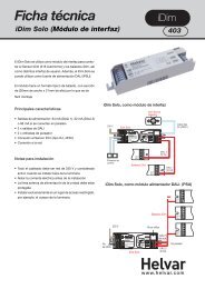
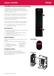
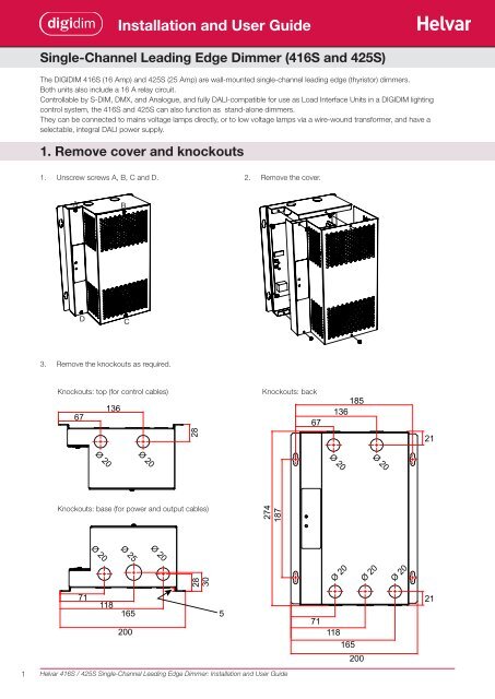
1. Remove cover <strong>and</strong> knockouts<br />
1. Unscrew screws A, B, C <strong>and</strong> D. 2. Remove the cover.<br />
A<br />
D<br />
3. Remove the knockouts as required.<br />
Knockouts: top (for control cables) Knockouts: back<br />
67<br />
Ø 20<br />
136<br />
B<br />
C<br />
Ø 20<br />
Knockouts: base (for power <strong>and</strong> output cables)<br />
71<br />
Ø 20<br />
118<br />
<strong>Installation</strong> <strong>and</strong> <strong>User</strong> <strong>Guide</strong><br />
Ø 25<br />
1 <strong>Helvar</strong> 416S / 425S Single-Channel Leading Edge Dimmer: <strong>Installation</strong> <strong>and</strong> <strong>User</strong> <strong>Guide</strong><br />
28<br />
30<br />
28<br />
165 5<br />
200<br />
Ø 20<br />
274<br />
187<br />
67<br />
71<br />
185<br />
136<br />
Ø 20<br />
Ø 20<br />
118<br />
165<br />
200<br />
Ø 20<br />
Ø 20<br />
Ø 20<br />
21<br />
21
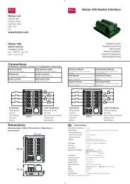
2. Mount to Wall<br />
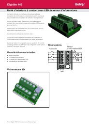
Mounting, Environmental <strong>and</strong> Clearance Requirements<br />
Mounting<br />
• Mount the chassis vertically on a flat surface.<br />
• Use screws with a head diameter between 7 mm <strong>and</strong> 9 mm.<br />
• Use wall plugs if necessary.<br />
• Mount chassis on wall using 4 screws.<br />
Environment<br />
• The ambient temperature must be between 0ºC <strong>and</strong> 40ºC.<br />
• Air humidity must be between 0% <strong>and</strong> 90% (non‑condensing).<br />
• The area must be adequately ventilated.<br />
• Do NOT install this product in a damp location.<br />
Clearance<br />
• Ensure enough space is left for ventilation: at 50 mm on each side of the unit. Refer to the mounting dimensions <strong>and</strong><br />
clearance diagrams below.<br />
• Leave sufficient clearance to allow cables <strong>and</strong> trunking to be connected.<br />
• The grilles must NOT be obstructed.<br />
Mounting dimensions <strong>and</strong> clearance (mm)<br />
50<br />
50<br />
50<br />
185<br />
200<br />
187<br />
274<br />
<strong>Helvar</strong> 416S / 425S Single-Channel Leading Edge Dimmer: <strong>Installation</strong> <strong>and</strong> <strong>User</strong> <strong>Guide</strong><br />
50<br />
R4.5<br />
R3<br />
14<br />
2
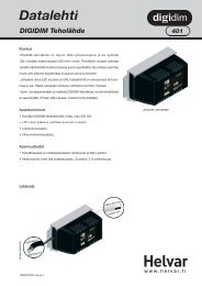
3. Electrical <strong>Installation</strong><br />
WARNING: BEFORE COMMENCING ANY ELECTRICAL WORK, ISOLATE THE<br />
ELECTRICITY SUPPLY AT THE MAIN DISTRIBUTION BOARD.<br />
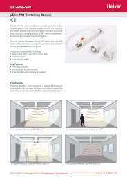
Connections<br />
With the cover removed, connect the earth, mains power, <strong>and</strong> the control wiring (see details below)<br />
Control<br />
inputs<br />
Mains<br />
Supply<br />
Input<br />
L<br />
N<br />
E<br />
TERM B 0V A SC C0 C1 C2 0V OVR<br />
S‑DIM;<br />
DMX<br />
Analogue<br />
(0‑10 V;<br />
1‑10 V)<br />
Override DALI<br />
(powered:<br />
DA- SC DA+ DA SC DA<br />
83 mA)<br />
L N N SWL DIM<br />
Cable access<br />
Use the knock‑outs for cable access. The gap between the back of the case <strong>and</strong> the wall may be used for cable entry.<br />
<strong>Helvar</strong> 416S / 425S Single-Channel Leading Edge Dimmer: <strong>Installation</strong> <strong>and</strong> <strong>User</strong> <strong>Guide</strong><br />
DALI<br />
(non‑powered)<br />
RELAY<br />
OUTPUT<br />
AC DIMMER<br />
OUTPUT<br />
L<br />
N<br />
E<br />
One removable DALI<br />
connector block is<br />
supplied with the<br />
416S/425S<br />
Load<br />
Outputs<br />
3
Mains Supply Input<br />
L N N SWL DIM<br />
Load outputs<br />
4 <strong>Helvar</strong> 416S / 425S Single-Channel Leading Edge Dimmer: <strong>Installation</strong> <strong>and</strong> <strong>User</strong> <strong>Guide</strong><br />
WARNING: THE SUPPLY INPUT EARTH MUST BE CONNECTED.<br />
Dimmer output Relay output (Switched load)<br />
L N N SWL DIM L N N SWL DIM<br />
Control inputs<br />
Control input connection terminals are screw terminals. These control inputs can be connected to the 416S/425S:<br />
DALI (non-powered)<br />
Powered DALI (83 mA)<br />
Analogue signal<br />
S-DIM<br />
DMX<br />
Override<br />
} Connect<br />
only one of these control inputs to the 416S/425S at one time.<br />
The Override input can be connected in addition to any of the other inputs.<br />
If the Powered DALI (83 mA) connection is used, the override input must be treated as<br />
potentially live.<br />
DALI<br />
One DALI connector block is supplied with the 416S/425S.<br />
Connect DALI wires to the connector block, <strong>and</strong> then attach the block to one of the DALI terminals (powered or non‑powered).<br />
Powered DALI:<br />
TERM B 0V A SC C0 C1 C2 0V OVR<br />
If the built‑in 83 mA DALI power supply is required, use the powered DALI connection.<br />
The powered DALI connection is not isolated from the other control outputs.<br />
DA- SC DA+<br />
Non-powered DALI:<br />
DA-: DALI -<br />
SC: Screen<br />
DA+: DALI +<br />
TERM B 0V A SC C0 C1 C2 0V OVR<br />
DA- SC DA+ DA SC DA<br />
To enable the DALI power connection:<br />
Tighten ALL terminal screws (this internally links the terminal poles).<br />
Ensure correct polarity of DA‑ <strong>and</strong> DA+.<br />
If adding another supply to the DALI network, remember that<br />
you must not exceed the DALI power supply limit of 250 mA.<br />
If the DALI network has an adequate power supply, use the non‑powered DALI connection.<br />
The non‑powered DALI connection is isolated from the other control outputs.<br />
DA SC DA<br />
DA: DALI<br />
SC: Screen<br />
DA: DALI<br />
!<br />
DA- SC DA+ DA SC DA
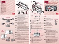
S-DIM / DMX<br />
S-DIM/DMX termination<br />
TERM B 0V A SC C0 C1 C2 0V OVR<br />
i ii<br />
TERM<br />
B SC 0V A<br />
C0 C1 C2 0V OVR<br />
i = S‑DIM or DMX Data Cable (from previous device)<br />
ii = S‑DIM or DMX Data Cable (to next device)<br />
iii = Link for Termination (if unit is at end of S‑DIM/DMX cable line)<br />
ANALOGUE:<br />
TERM B 0V A SC C0 C1 C2 0V OVR<br />
5 <strong>Helvar</strong> 416S / 425S Single-Channel Leading Edge Dimmer: <strong>Installation</strong> <strong>and</strong> <strong>User</strong> <strong>Guide</strong><br />
DA- SC DA+ DA SC DA<br />
i<br />
iii<br />
TERM B SC 0V A<br />
C0 C1 C2 0V OVR<br />
Note: Keep unscreened wire lengths to a minimum<br />
DA- SC DA+ DA SC DA<br />
Typical analogue control circuits are shown below. One input only (0 - 10 V or 1 - 10 V) can be used at one time.<br />
0 - 10 V (source)<br />
0 V 10 V<br />
C0<br />
0 - 10 V<br />
INPUT<br />
C1 C2<br />
OVERRIDE:<br />
TERM B 0V A SC C0 C1 C2 0V OVR<br />
1 - 10 V (sink)<br />
0 V 1 - 10 V<br />
C0<br />
C1 C2<br />
DA- SC DA+ DA SC DA<br />
If the override input connection is short‑circuited, e.g. by contact closure on an alarm system, the dimmer is set to its override<br />
level, regardless of external control signals.<br />
0V OVR<br />
Vin < 1.5 V<br />
Ishort = 1 mA<br />
To provide output level override functionality, wire a switch between the ‘0 V’<br />
<strong>and</strong> ‘OVR’ terminals.<br />
Switch closure sets the light output of the dimmer channel to the override<br />
level.<br />
The override level can be set using the interface (see section 5: The<br />
416S/425S Menu) or Designer software.<br />
If the Powered DALI (83 mA) connection is used, the override input must be<br />
treated as potentially live.
4: Power Up<br />
During power up, the following sequence is displayed on the LED Control Panel.<br />
Start-up Sequence:<br />
1. All segments on 2. Product model 3. Software version 4. Normal Operation<br />
(416 or 425)<br />
(Status Display)<br />
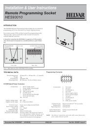
5. The 416S/425S Status Display (default display)<br />
The Status display is the default view during operation.<br />
The Status display shows:<br />
‑ the relay (switched) level (left digit)<br />
‑ the dimmer level (right digit)<br />
‑ power <strong>and</strong> input / output indicators<br />
You can view <strong>and</strong> directly adjust the relay <strong>and</strong><br />
dimmed outputs from the status display.<br />
Key <strong>and</strong> LED Descriptions:<br />
0.5 sec 0.5 sec 0.5 sec<br />
Use the two push buttons (below the the display) to<br />
navigate the features menu <strong>and</strong> change parameters.<br />
If neither of the buttons is pressed for 10 seconds,<br />
the Status display is shown.<br />
S-DIM/DMX activity or<br />
Analogue input mode<br />
Relay<br />
output<br />
level<br />
Relay (Switched)<br />
This shows the following digits: 0 (0‑9%), 1 (10‑19%), 2 (20‑29%), 3 (30‑39%), 4 (40‑49%), 5 (50‑59%), 6 (60‑69%), 7 (70‑79%),<br />
8 (80‑89%), 9 (9‑99%) <strong>and</strong> F (Full: 100%).<br />
Dimmer channel level<br />
This shows the following digits: 0 (0‑9%), 1 (10‑19%), 2 (20‑29%), 3 (30‑39%), 4 (40‑49%), 5 (50‑59%), 6 (60‑69%), 7 (70‑79%),<br />
8 (80‑89%), 9 (9‑99%) <strong>and</strong> F (Full: 100%).<br />
Power indicator<br />
The power indicator (top segment of the middle digit) is always on when the 416S/425S is powered up.<br />
S-DIM / DMX activity indicator<br />
The S‑DIM / DMX activity indicator (centre segment of the middle digit) is normally off, <strong>and</strong> flashes on intermittently to indicate<br />
S‑DIM / DMX activity (communications).<br />
Analogue<br />
The centre segment of the middle digit flashes when Analogue mode is selected.<br />
Software override indicator<br />
The decimal point on the left is illuminated to indicate software override from the override test menu.<br />
DALI power / activity indicator<br />
The DALI indicator (bottom segment of the middle digit) is off if there is no DALI power, <strong>and</strong> on if DALI power is present. If any<br />
DALI activity is directed to a channel within the device, the indicator blinks off.<br />
Hardware (wired) override indicator<br />
The side segments of the middle digit flash to indicate wired override.<br />
Powered<br />
DALI<br />
connection<br />
indicator<br />
6 <strong>Helvar</strong> 416S / 425S Single-Channel Leading Edge Dimmer: <strong>Installation</strong> <strong>and</strong> <strong>User</strong> <strong>Guide</strong><br />
Power<br />
indicator<br />
Dimmer<br />
channel<br />
output level
5: The 416S/425S Menu<br />
How to navigate the menu <strong>and</strong> configure the 416S/425S<br />
Go to the next item in the main menu<br />
Press <strong>and</strong> hold both buttons to step through the main menu options.<br />
Select a menu option (access a submenu);<br />
Select the next item in a submenu<br />
When you have navigated to the main menu option you want,<br />
press (<strong>and</strong> release) either of the buttons to access the submenu.<br />
To step through the submenu items, press (<strong>and</strong> release) either of the buttons.<br />
Adjust a value / parameter (from submenu);<br />
Adjust a value / parameter (from main menu)<br />
+<br />
-<br />
Confirm (save) a setting<br />
When you have selected an item in the submenu, to adjust that setting, press <strong>and</strong> hold one of the buttons.<br />
The currently stored setting will show in non‑flashing digits.<br />
Options or values shown in flashing digits are not yet confirmed.<br />
To confirm the new value / parameter, press <strong>and</strong> hold both buttons.<br />
When you are in the main menu, to adjust the last viewed setting in a main menu option, press <strong>and</strong> hold one<br />
of the buttons.<br />
When you have adjusted a setting, press <strong>and</strong> hold both buttons to confirm the change (save the change to<br />
system memory)<br />
Return to Status Display (default display)<br />
If no button is pressed for 10 seconds, the Status Display is shown.<br />
The Status Display shown here indicates that the Relay (switched) level is zero, <strong>and</strong> the level is zero.<br />
Examples of adjusting settings<br />
View <strong>and</strong> change switched <strong>and</strong> dimmer levels<br />
1<br />
2<br />
Set S-DIM or DMX address of the dimmer channel<br />
When using S‑DIM or DMX control, you can set a specific address for the relay (switched), dimmer, or both. The default address is 1.<br />
1<br />
3 5<br />
7 9<br />
2<br />
3<br />
7 <strong>Helvar</strong> 416S / 425S Single-Channel Leading Edge Dimmer: <strong>Installation</strong> <strong>and</strong> <strong>User</strong> <strong>Guide</strong><br />
4<br />
5<br />
+<br />
-<br />
... [10 s] ...<br />
With the status display (1) showing, press either button once (2) to display REl or Chl (3). Press <strong>and</strong> hold the top or bottom button (4) to adjust the level.<br />
When the required level is reached (5: this example shows 46%), release the button.<br />
After 10 seconds, the Status display is shown (6). The digit 4 indicates a dimmer channel level of 40‑49%.<br />
4 6 8<br />
With the status display (1) showing, press <strong>and</strong> hold both buttons (2) to step through the menu.<br />
When the display shows AdS (3), press the top button once (4) to display Chl.<br />
When Chl is shown (5), press <strong>and</strong> hold one of the buttons (6) until the required address value is shown (7: this example is 32).<br />
Press both buttons (8) to store the setting. The display flashes 888 when the value is stored (9).<br />
Note 1: When the dimmed <strong>and</strong> relay channels are separated (ChP = SEP: see Channel Pairing in Menu Options), the base address option can be<br />
used to set both channel addresses at the same time.<br />
Note 2: For DMX control input, enable DMX. For S‑DIM control input, disable DMX. See Enable / Disable DMX in Menu Options.<br />
6<br />
+<br />
-
Menu options<br />
Navigate through the 416S/425S menus using the push buttons located below the display.<br />
Main menu Submenu Options Notes<br />
Press <strong>and</strong> hold<br />
both buttons to<br />
step through<br />
Status display<br />
Levels<br />
Left: Relay<br />
Right: Dimmer<br />
S-DIM or DMX Address<br />
DALI Address<br />
DMX (Enable / Disable)<br />
Analogue<br />
Press (<strong>and</strong> release) top /bottom<br />
button to enter <strong>and</strong> step through<br />
submenu<br />
Output type (dimmed output)<br />
Minimum fade time<br />
Channel pairing<br />
Press <strong>and</strong> hold top/bottom<br />
button to alter / select.<br />
0: 0‑9%;<br />
1: 10‑19%<br />
2: 20‑29%)<br />
3: 30‑39%<br />
4: 40‑49%<br />
5: 50‑59%<br />
6: 60‑69%<br />
7: 70‑79%<br />
8: 80‑89%<br />
9: 9‑99%<br />
F: 100%<br />
(Full)<br />
S-DIM<br />
1 – 254; Disabled (Default: 1)<br />
S‑DIM base: 1 – 253<br />
DMX<br />
1 ‑ 512; Disabled (Default: 1)<br />
DMX base: 1 ‑ 511<br />
DALI Address:<br />
1 – 64;<br />
‑‑‑ (=Removed);<br />
diS (=Disabled)<br />
DALI Base:<br />
1 – 63 (Default: 1);<br />
8 <strong>Helvar</strong> 416S / 425S Single-Channel Leading Edge Dimmer: <strong>Installation</strong> <strong>and</strong> <strong>User</strong> <strong>Guide</strong><br />
Off;<br />
On<br />
Off;<br />
0.10;<br />
1.10<br />
Output Output type Control Protocol<br />
t 0 Non Dim All<br />
t 1 Linear S‑DIM / DMX<br />
t 2 Square S‑DIM / DMX<br />
t 3 S‑law S‑DIM / DMX<br />
t 4 DALI logarithmic DALI<br />
t 5 DALI SSL DALI<br />
t 6 DALI linear DALI<br />
t 7 Analogue Analogue<br />
1.00; 0.50; 0.15; 0.02 s<br />
(Default: 1.00 s)<br />
P-1 (Paired)<br />
SEP (Separate = non‑paired)<br />
Set the output levels of the relay (switched) output [REl],<br />
Dimmer output [Chl], or both [ALL: available only when<br />
channels are not paired].<br />
Output levels:<br />
Left digit: Relay (switched) output<br />
Right digit: Dimmer<br />
Set the S‑DIM or DMX address of the relay (switched) output<br />
[REl], Dimmer output [Chl], or S‑DIM / DMX base address<br />
[bAS].<br />
The base address option is available only when channels are<br />
not paired (ChP = SEP).<br />
Set the DALI address of the relay (switched) output [REl],<br />
Dimmer output [Chl], or DALI base address [bAS].<br />
The base address option is available only when channels are<br />
not paired (ChP = SEP).<br />
If DALI status is ‑‑‑ (Removed), the next time you connect<br />
it to a controller program or router, the DALI address will be<br />
re‑allocated. If DALI status is diS (disabled) the address will<br />
not be re‑allocated.<br />
Disable [Off] or enable [On] the DMX control input.<br />
For DMX control input, enable DMX.<br />
For S‑DIM control input, disable DMX.<br />
Disable [Off] or enable Analogue control input:<br />
0 ‑ 10 V : source<br />
1 ‑ 10 V : sink<br />
Notes on output types:<br />
Under S‑DIM/DMX control, default<br />
is t 1<br />
Under DALI control, default is t 4<br />
Under Analogue control, default is t 7<br />
Select the minimum fade time for the relay (switched) output<br />
[REl], Dimmer output [Chl] individually, or both channels (ALL).<br />
Unpair the the relay (switched) output <strong>and</strong> dimmer output, so<br />
that they are adjusted separately (SEP), or pair them (P‑1).
Override level<br />
Override test<br />
DALI minimum level (DALI mode only)<br />
Switch-on level (S-DIM / DMX mode only)<br />
Maximum load level<br />
Hysteresis<br />
SCR drive mode<br />
Reset to defaults<br />
9 <strong>Helvar</strong> 416S / 425S Single-Channel Leading Edge Dimmer: <strong>Installation</strong> <strong>and</strong> <strong>User</strong> <strong>Guide</strong><br />
0 – 100; --- (=not set) Set override level for the relay (switched) output [REl], Dimmer<br />
output [Chl] individually, or both (ALL).<br />
If the override input connection is short‑circuited, e.g. by<br />
contact closure on an alarm system, the relay <strong>and</strong> dimmer<br />
outputs are set to their override level, regardless of external<br />
control signals.<br />
Off;<br />
On<br />
Test the override mode [On] or deactivate override test [Off].<br />
When the override test is running, the relay <strong>and</strong> dimmer<br />
outputs are set to their override level, regardless of external<br />
control signals, <strong>and</strong> the side segments of the central digit of<br />
the Status display will flash.<br />
0.1; 1 – 100%. Set the minimum DALI lighting level for the relay (switched)<br />
output [REl], Dimmer output [Chl] individually, or both (ALL).<br />
Minimum DALI lighting level is the minimum level achieved when<br />
the load is turned on, no matter what scene is called or level is set.<br />
For example, if you set a minimum level of 50% <strong>and</strong> call scene<br />
4 (at 25% level), the channel output level will be 50%.<br />
S-DIM<br />
2 – 64%<br />
DMX<br />
0.1; 1 – 64%<br />
[P-1 =Channels paired]<br />
1 – 100%.<br />
Default: 100%<br />
Set the switch‑on level for the relay (switched) output [REl],<br />
Dimmer output [Chl] individually, or for both (ALL).<br />
The switched load or dimmed load (or both) will not turn on<br />
unless it receives a comm<strong>and</strong> to go to or above this level.<br />
Limit the maximum output level of the relay (switched) output<br />
[REl], Dimmer output [Chl] individually, or both (ALL).<br />
This setting affects the level at which the the relay (switched)<br />
output [REl], dimmer output [Chl], or for both (ALL) turn off.<br />
When hysteresis is on, the switch‑off level is 80% of the<br />
switch‑on level. At or below the switch‑off level, the channel<br />
will be off.<br />
By default:<br />
‑ When hysteresis is on <strong>and</strong> the signal rises to 2%, the load<br />
turns on; when it falls to 0%, the load turns off.<br />
‑ When hysteresis is off (default setting) <strong>and</strong> the signal rises to<br />
2%, the load turns on; when it falls to 1%, the load turns off.<br />
Certain loads may need a different dimming method:<br />
tri: triac mode<br />
Scr: SCR mode<br />
Hyb: Hybrid mode (default)<br />
To reset the 416S/425S to the original settings (defaults),<br />
press <strong>and</strong> hold one of the buttons for 10 seconds.<br />
Restoring factory settings returns all connected lighting to<br />
default levels immediately.
Technical Data<br />
Power <strong>and</strong> Protection<br />
Power consumption: 1.3 W (with no output load)<br />
Heat dissipation: 416S: 39 W with maximum load (resistive); 425S: 67 W with maximum load (resistive)<br />
External protection The mains supply input must be externally protected by an MCB or fuse of a suitable rating.<br />
416S: 16 A Type C MCB maximum. 425S: 25 A Type C MCB maximum.<br />
Thermal protection: Control board – resettable fuse<br />
Power devices – thermal sensing<br />
Mains supply input<br />
Connections (L, N, E): Solid: ≥ 6 mm² ; Str<strong>and</strong>ed: ≥ 4 mm²<br />
Terminal type: Screw terminals<br />
Mains supply voltage: 85 VAC to 264 VAC, 45 ‑ 65 Hz<br />
Cable strip length: 8 mm<br />
Control inputs<br />
DALI<br />
Connections: 1x DALI (st<strong>and</strong>ard, non‑powered);<br />
1x DALI powered (83 mA).<br />
2‑part DIGIDIM connector with paired screw terminals (one supplied with unit)<br />
Cable type <strong>and</strong> size: 0.5 mm 2 — 1.5 mm 2 str<strong>and</strong>ed or solid<br />
Cable strip length: 6 mm<br />
DALI consumption: 2 mA<br />
DALI supply output: Powered DALI: 83 mA (max), 20 VDC (nominal)<br />
DALI data transfer: DALI st<strong>and</strong>ard IEC62386, with <strong>Helvar</strong> extensions<br />
S-DIM / DMX inputs<br />
Connections: S‑DIM <strong>and</strong> DMX use the same input connections<br />
Terminal type: Screw terminals<br />
Cable type <strong>and</strong> size: 0.22 mm² — 1.5 mm² ; low‑loss RS485 Type (multi‑str<strong>and</strong>ed, twisted <strong>and</strong> shielded).<br />
One twisted pair for A <strong>and</strong> B (85 Ω to 100 Ω impedance), one core or twisted pair for 0 V, <strong>and</strong><br />
shield for screen. Example cable: Belden 8102 or Alpha 6222C<br />
Cable strip length: 6 mm<br />
Maximum cable length: 1000 m (low‑loss cable)<br />
S-DIM data transfer: <strong>Helvar</strong> protocol (RS485, 115 kbps)<br />
DMX data transfer: DMX512‑A protocol<br />
Analogue input<br />
Terminal type: Screw terminals<br />
Cable type <strong>and</strong> size: 2‑wire; 0.22 mm 2 — 1.5 mm 2 (screened <strong>and</strong> twisted)<br />
Maximum cable length: 50 m<br />
Override input<br />
Terminal type: Screw terminals<br />
Cable type <strong>and</strong> size: 2‑wire; 0.22 mm 2 — 1.5 mm 2 (screened <strong>and</strong> twisted)<br />
Cable strip length: 6 mm<br />
Maximum cable length: 50 m<br />
Voltage <strong>and</strong> current: Input voltage: Vin < 1.5 V; Short‑circuit current Ishort = 1 mA<br />
10 <strong>Helvar</strong> 416S / 425S Single-Channel Leading Edge Dimmer: <strong>Installation</strong> <strong>and</strong> <strong>User</strong> <strong>Guide</strong>
Load outputs<br />
Dimmed output<br />
Terminal type: Screw terminals<br />
Cable type <strong>and</strong> size: Solid: ≥ 6 mm² ; Str<strong>and</strong>ed: ≥ 4 mm²<br />
Cable strip length: 8 mm<br />
Relay output (Switched load output)<br />
Terminal type: Screw terminals<br />
Cable type <strong>and</strong> size: Solid: ≥ 6 mm² ; Str<strong>and</strong>ed: ≥ 4 mm²<br />
Cable strip length: 8 mm<br />
Load current: 416S: 16 A; 425S: 16 A<br />
Relay contacts: High inrush<br />
Conformity <strong>and</strong> St<strong>and</strong>ards<br />
EMC Emission: EN 61000‑6‑3<br />
Immunity: EN 61547<br />
Harmonics: EN 61000‑3‑2*<br />
* May be subject to conditional connection for use above 16 A.<br />
Safety: EN 60950<br />
Isolation: 4 kV<br />
IP rating: IP 20<br />
Environmental: Complies with WEEE <strong>and</strong> RoHS directives<br />
Mechanical Data<br />
Mounting: Vertical mounted, secured by four ‘keyhole’ slots.<br />
Dimensions: 200 mm (W) x 274 mm (H) x 104 mm (D)<br />
Weight: 416S: 2 kg<br />
425S: 2.6 kg<br />
Housing: Powder coated steel (grey)<br />
Operating <strong>and</strong> Storage Conditions<br />
Ambient Temperature: 0ºC — +40ºC<br />
Storage Temperature: ‑10°C — +70°C<br />
Relative Humidity: Max 90%, non‑condensing<br />
11 <strong>Helvar</strong> 416S / 425S Single-Channel Leading Edge Dimmer: <strong>Installation</strong> <strong>and</strong> <strong>User</strong> <strong>Guide</strong>
Data subject to change without notice<br />
<strong>Helvar</strong> 416S / 425S Single-Channel Leading Edge Dimmer: <strong>Installation</strong> <strong>and</strong> <strong>User</strong> <strong>Guide</strong><br />
www.helvar.com<br />
Doc. 7860279, issue 02<br />
16.11.2012