Installation & User Instructions Pre-Wired Cabinets - Helvar
Installation & User Instructions Pre-Wired Cabinets - Helvar
Installation & User Instructions Pre-Wired Cabinets - Helvar

Create successful ePaper yourself
Turn your PDF publications into a flip-book with our unique Google optimized e-Paper software.
<strong>Installation</strong> & <strong>User</strong> <strong>Instructions</strong><br />
<strong>Pre</strong>-<strong>Wired</strong> <strong>Cabinets</strong><br />
HES12xxx & HES24xxx range<br />
INTRODUCTION<br />
These instructions relate to the installation of an Imagine PRE-WIRED<br />
CABINET type HES12xxx or HES24xxx. For full details on operation,<br />
please refer to the <strong>User</strong> Guide (part no. I293GB).<br />
SITING REQUIREMENTS<br />
The installation site must meet the following criteria:<br />
Temperature range: 0C – 35C.<br />
Humidity: 0% – 90% non-condensing.<br />
There should be sufficient ventilation to dissipate the heat produced<br />
from the cabinet(s) when all outputs are at their maximum level and<br />
loading. The door ventilation grilles must be kept free from obstruction<br />
at all times.<br />
Model > HES12000 HES12200 HES12100 HES12300<br />
Max. heat dissipation 225W 615W 210W 600W<br />
Model > HES24000 HES24200 HES24100 HES24300<br />
Max. heat dissipation 435W 1215W 420W 1200W<br />
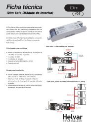
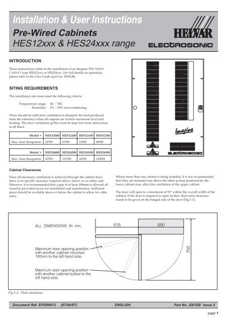
Cabinet Clearances<br />
Since all necessary ventilation is achieved through the cabinet door,<br />
there is no specific clearance required above, below or on either side.<br />
However, it is recommended that a gap of at least 100mm is allowed all<br />
round to provided access for installation and maintenance. Sufficient<br />
space should be available above or below the cabinet to allow for cable<br />
entry.<br />
Fig.1-1: Door clearances.<br />
Where more than one cabinet is being installed, it is not recommended<br />
that they are mounted one above the other as heat produced by the<br />
lower cabinet may affect the ventilation of the upper cabinet.<br />
Thedoorwillopentoamaximumof90°withintheoverallwidthofthe<br />
cabinet. If the door is required to open further, then extra clearance<br />
needs to be given on the hinged side of the door (Fig.1-1).<br />
Document Ref. EPD04013 (07/04/97) ENGLISH Part No. I261GB issue 2<br />
page 1
MOUNTING OPTIONS<br />
The cabinet can be installed in a variety of ways depending on the<br />
location and user requirements, but must be installed vertically.<br />
The important consideration for any method of installation is that the<br />
cabinets are heavy and must be secured accordingly.<br />
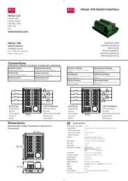
Wall Fixing<br />
There are number of ‘keyhole’ type fixing holes provided on the back of<br />
both sizes of cabinet which may be used for wall fixing (Fig.1-2).<br />
It is recommended that the HES97520 Wall Fixing Kit be used.<br />
Wall Fixing Kit (HES97520)<br />
A kit of parts is available to assist wall fixing. The kit comprises two<br />
metal plates, each with two threaded studs and five fixing holes. The<br />
plates are intended to be secured to the wall with suitable screws or bolts<br />
(not supplied), with the cabinet then being clamped into position on each<br />
stud with nuts and washers provided. Full instructions are included<br />
with the kit.<br />
WARNING<br />
Both wall plates must be fitted, and you should ensure that both the wall and<br />
the plate fixings are capable of supporting the weight of the cabinet.<br />
Remember to take into account that the cabinet may be leant upon or put<br />
under other such stresses during installation and use.<br />
52.0<br />
734.4<br />
630.4<br />
Floor Plinth (HES97540)<br />
A metal plinth is available allowing the cabinet to stand directly on the<br />
floor. This is particularly recommended for the HES24xxx range of<br />
cabinets.<br />
Fitting the plinth requires the removal of the two cable entry plates from<br />
the base of the cabinet. The plinth is then secured to the base of the<br />
cabinet with self-tapping screws provided.<br />
Cable entry is not possible through the base of the cabinet when the<br />
plinth is fitted.<br />
WARNING<br />
If the cabinet is floor mounted, it is essential that the top of the cabinet is<br />
secured to a rear wall (or another supporting arrangement) to prevent the<br />
unit from tipping. One of the wall fixing plates detailed above may be used<br />
for this purpose.<br />
Back-to-back<br />
20.0<br />
550.0<br />
510.0<br />
20.0<br />
30.0<br />
11.0<br />
HES12XXX<br />
RANGE<br />
Ø13.0<br />
Fig.1-2: Dimensions of cabinet rear fixing holes.<br />
Two cabinets fitted with floor plinths may be installed back-to-back. The<br />
two cabinets must be bolted together top and bottom using suitable M10<br />
nuts, bolts and washers (not supplied) through the rear fixing holes.<br />
550.0<br />
510.0<br />
TOP TOP<br />
ALL<br />
DIMENSIONS<br />
IN mm.<br />
1141.4<br />
52.0<br />
518.7<br />
518.7<br />
HES24XXX<br />
RANGE<br />
Document Ref. EPD04013 (07/04/97) ENGLISH Part No. I261GB issue 2<br />
page 2
REVERSING THE DOOR<br />
The door on each type of cabinet is designed to be reversible. This is<br />
achieved by transferring the various fittings to the mounting points on<br />
the opposite sides of the door and cabinet, as follows:<br />
WARNING<br />
If the cabinet is already connected to the mains supply, for your own safety<br />
always ensure that the supply is isolated before attempting to remove the<br />
door.<br />
Ensure that all earth leads are reconnected.<br />
1. Unlock the door using the key provided.<br />
2. Open the door and disconnect the earth lead from the stud on the back<br />
of the door.<br />
3. Remove the collars from the top and bottom hinge pins by loosening<br />
the grub screw with an M4 allen key.<br />
4. Partially close the door (with the open edge approximately 50mm from<br />
the cabinet), grasp the door firmly at the top and bottom, and lift it<br />
upwards off of the hinge pins.<br />
5. Transfer the lock and finger plate to the opposite side of the door in<br />
place of the hole plug (which should be transferred to the vacant<br />
hole). Ensure that the lock is orientated correctly before fixing (see<br />
Fig.1-3).<br />
6. Remove the two hinge plates from the cabinet, move the hinge pin to<br />
the other hole in each plate, and refit the hinge plates to the<br />
opposite side of the cabinet (see Fig.1-4).<br />
NOTE There are two groups of four holes where the hinge brackets are to be<br />
mounted; use the top two holes only.<br />
7. Transferthelatchplateandlocatingstudtotheoppositesideofthe<br />
cabinet, noting that the latch plate is inverted (see Fig.1-5).<br />
8. Disconnect the door earth lead from the side panel of the cabinet and<br />
transfer it to the opposite side panel earth stud.<br />
NOTE To improve accessibility when fitting or removing the lead from the<br />
right-hand side panel, remove the four screws securing the panel to<br />
the cabinet and ease the panel forward. Once the earth wire is secure,<br />
refit the side panel ensuring that the fixing screws are securely<br />
tightened.<br />
9. Offer the door up to the cabinet in the ‘almost closed’ position and<br />
hook it on to the hinge pins.<br />
10. Open the door and connect the earth wire to the door earth stud.<br />
11. Resecure the collars to the top and bottom hinge pins.<br />
Removing the Side Panels<br />
To assist with the physical and electrical installation of the cabinet, the<br />
side panels can be removed. To remove the side panel with the door<br />
hinged to it, first remove the door as described in steps 1 to 4 on page 3,<br />
then proceed as follows:<br />
WARNING<br />
If the cabinet is already connected to the mains supply, for your own safety<br />
always ensure that the supply is isolated before attempting to remove the<br />
sides.<br />
Ensure that all earth leads are reconnected.<br />
1. Disconnect the earth lead to the appropriate side, which is located at<br />
the bottom front of the panel.<br />
2. Remove the four screws (two top, two bottom) securing the side panel<br />
to the cabinet.<br />
3. Slide the panel forwards until the rear retaining lugs are free, then lift<br />
the panel away. When replacing ensure that the rear lugs locate<br />
correctly on the rear panel flanges and that the earth lead is<br />
reconnected.<br />
With the door lock mounted<br />
on the right-hand side<br />
(standard)<br />
With the door lock mounted<br />
on the left-hand side<br />
(standard)<br />
‘LOCKED’<br />
‘LOCKED’<br />
Fig.1-3: Door lock mounting positions.<br />
Hinge<br />
mountedonthe<br />
left-hand side<br />
(standard)<br />
Fig.1-4: Hinge plate and hinge pin positions.<br />
With the door<br />
hinged on the<br />
left-hand side<br />
(standard)<br />
With the door<br />
hinged on the<br />
right-hand side<br />
Fig.1-5: Latch plate, locating stud and earth wire.<br />
‘UNLOCKED’<br />
‘UNLOCKED’<br />
Hinge<br />
mountedonthe<br />
right-hand side<br />
Document Ref. EPD04013 (07/04/97) ENGLISH Part No. I261GB issue 2<br />
page 3
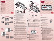
Fig.1-6: Cable entry cut-out and plate dimensions.<br />
CABLE ENTRY POINTS<br />
There are cable entry cut-outs located on the top and bottom panels of all<br />
types of cabinet. These are covered with plates secured by screws.<br />
The plates may be removed completely for access or can be cut or drilled<br />
to allow for fixing to conduit and trunking systems. Fig.1-6 shows the<br />
cut-out and plate dimensions viewed from the top and these are the<br />
same for both the top and bottom panels.<br />
The large left-hand cut-out is for mains input and output cables, whilst<br />
the smaller right-hand cut-out is for FELV (Functional Extra-Low<br />
Voltage) cables.<br />
Terminal Cover Panel<br />
A plastic cover is fitted around the MCB’s, covering the various input<br />
and output terminals. The panel provides secondary insulation and also<br />
identifies the various MCB’s and power connections.<br />
The panel is retained by several pairs of plastic clips which are attached<br />
to the DIN rail. To remove the panel, squeeze the lugs of each pair<br />
together in turn and ease the panel forwards until completely free. To<br />
refit, align the panel with each pair of clips and firmly push the panel<br />
into position.<br />
A channel is provided on the panel for a slot-in label, on which details of<br />
the input supply, MCB and output functions should be recorded. The<br />
label (with its clear protective cover) slides out from the top of the<br />
channel.<br />
REAR EDGE<br />
INPUT SUPPLY<br />
Input Current (3-phase)<br />
The table below shows the maximum possible current that may be<br />
drawn with all outputs at maximum load and level. The input supply<br />
must be externally protected.<br />
Model Max.<br />
current<br />
Phase 1<br />
Max.<br />
current<br />
Phase 2<br />
Max.<br />
current<br />
Phase 3<br />
Max.<br />
current<br />
TOTAL<br />
HES12000 40A 40A 41A 121A<br />
HES12200 * 80A 80A 81A 241A<br />
HES12100 40A 40A 40A 120A<br />
HES12300 * 80A 80A 81A 241A<br />
HES24000 80A 80A 81A 241A<br />
HES24200 * 160A 160A 161A 481A<br />
HES24100 80A 80A 80A 240A<br />
HES24300 * 160A 160A 161A 481A<br />
* These cabinets are fitted with a cooling fan.<br />
Input Current (single phase)<br />
The PRE-WIRED CABINET is primarily intended for use with a 3-phase supply.<br />
If the cabinet is to be connected to a single phase supply, the maximum<br />
current that can be drawn is limited by the capacity of the neutral<br />
bus-bar on the output terminals.<br />
Maximum current:<br />
(single phase operation)<br />
160A.<br />
The input supply must be externally protected.<br />
Document Ref. EPD04013 (07/04/97) ENGLISH Part No. I261GB issue 2<br />
page 4
INPUT CONNECTIONS<br />
Earth Terminal<br />
This is located at the top of the DIN rail and is coloured green and<br />
yellow.<br />
Maximum cable size: 35mm 2 .<br />
Stripping length: 20mm.<br />
Screw torque setting: 2.5 Nm.<br />
Live Input Terminals (Phase 1, 2 & 3)<br />
The input MCB’s are are arranged in three groups (one for each phase).<br />
All of the input terminals within each group are linked by an internal<br />
bus-bar. Always ensure that the connection to each MCB group is made<br />
via the MCB nearest the centre of each group to provide equal load<br />
distribution along the bus-bar.<br />
Connection is achieved by various methods according to the cabinet type<br />
and size of the input cables; these are illustrated in Fig.1-10 and 1-11.<br />
Cables of 16mm 2 size (or less) should be fitted directly into the MCB<br />
input terminals. Cables of 35mm 2 size should use the adapter(s) supplied<br />
and be connected in the positions indicated. Both screws on each adapter<br />
must be fully screwed-in to ensure that the cable is securely clamped.<br />
Maximum cable size: 35mm 2 (with adapter – see note below).<br />
16mm 2 (MCB terminal).<br />
Stripping length: 13mm (one adapter).<br />
30mm (two adapters).<br />
10mm (MCB terminal).<br />
Screw torque setting: 2Nm (MCB only).<br />
NOTE Theadaptersaresuitablefor35mm 2 cable only. If 25mm 2 cable is<br />
used then a different type of adapter must be fitted (available on<br />
request).<br />
Neutral Terminal<br />
This is located on the neutral bus-bar for the power output terminals.<br />
The output terminals are arranged in two groups with the neutral<br />
terminal situated between them.<br />
Maximum cable size: 35mm 2 .<br />
Stripping length: 15mm.<br />
Screw torque setting: 2.5 Nm.<br />
MCB ANTI-TAMPER CLIP<br />
On cabinets fitted with a cooling fan, the MCB for the fan unit is fitted<br />
with an anti-tamper clip. This is used to prevent the MCB from being<br />
switched-off accidently.<br />
To remove the clip, slide back the plastic sleeve and compress the two<br />
retaining springs until they disengage with the holes in the MCB body<br />
(Fig.1-7). When refitting, ensure that the MCB is switched-on and that<br />
the clipis positioned on the left-hand side.<br />
Fig.1-7: Removing the MCB ant-tamper clip.<br />
Fig.1-8: Main input terminals for HES12xxx range.<br />
Document Ref. EPD04013 (07/04/97) ENGLISH Part No. I261GB issue 2<br />
page 5
Fig.1-9: Main input terminals for HES24xxx range.<br />
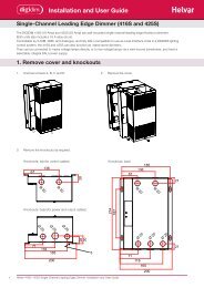
HES12XXX Range<br />
2<br />
Input cable 16mm or less<br />
Connect cable directly to the<br />
3rd position from the top of<br />
each MCB group.<br />
Location of SCENESET and FAN<br />
MCBs (phase 3 only - where fitted).<br />
Input cable 35mm 2<br />
Use adapter in 3rd position<br />
from the top of each<br />
MCB group.<br />
Location of SCENESET and FAN<br />
MCBs (phase 3 only - where fitted).<br />
Fig.1-10: HES12xxx - live input connection methods.<br />
HES24000 & HES24100<br />
Input cable 35mm 2<br />
Use adapter in the 5th position<br />
from the top of each MCB group.<br />
Location of SCENESET and FAN<br />
MCBs (phase 3 only - where fitted).<br />
HES24200 & HES24300<br />
Input cable 35mm 2<br />
Use adapters in 4th and 5th<br />
positions from the top of<br />
each MCB group.<br />
Location of SCENESET and FAN<br />
MCBs (phase 3 only - where fitted).<br />
Fig.1-11: HES24xxx - live input connection methods.<br />
Document Ref. EPD04013 (07/04/97) ENGLISH Part No. I261GB issue 2<br />
page 6
OUTPUT POWER CONNECTIONS<br />
The connections for each output circuit are located at the bottom of the<br />
DIN mounting rail. A ‘triple’ terminal arrangement is provided giving a<br />
separate neutral and earth terminal for each controlled live output,<br />
allowing easy connection and identification of each circuit (see Fig.4-1).<br />
Cable Type<br />
The connecting cables should conform with the following specification:<br />
Suitable cable type: Solid, stranded or flexible.<br />
Cable size: 1.5mm 2 –4mm 2 .<br />
Stripping length: 10mm.<br />
Output Loading<br />
The maximum load for each output must not exceed the rating of the<br />
input MCB. If an output is to be used with a switched load (i.e.<br />
non-dimming), it is recommended that the load should not exceed 80%<br />
of the MCB rating to avoid nuisance tripping.<br />
Method of Connection<br />
The terminals are of a screw-less cage-clamp design and connection is<br />
achieved as follows (see Fig.1-12):<br />
1. Insert the blade of a small flat-bladed screwdriver as far as it will go into<br />
the terminal release point (square hole) next to the connecting point.<br />
2. Push the screwdriver handle to the right, which will open the<br />
cage-clamp.<br />
3. Insert the cable into the connecting point. (If stranded wire is used,<br />
ensure that the strands are twisted together).<br />
4. Release pressure on the screwdriver, and check the security of the<br />
connection by pulling on the cable.<br />
IMPORTANT NOTE<br />
Only one cable should be inserted into each terminal to ensure a reliable<br />
connection. If additional cables are needed (e.g. for Parallel Operation), a<br />
separate junction box or splitter must be used.<br />
1<br />
3<br />
4<br />
2<br />
Ensure correct orientation of the<br />
blade, i.e. with ‘flats’ facing left to<br />
right. Width of the blade should<br />
be between 3 – 3.5mm.<br />
Fig.1-12: Connecting to ‘cage-clamp’ output terminals.<br />
Fig.1-13: Power output connections.<br />
Parallel Operation<br />
When two DIMMER outputs are required to be used in parallel to drive a<br />
higher load, a separate feed must be taken from the two output terminals<br />
and joined together in a junction box. This ‘double’ feed may then be<br />
connected to the load circuit.<br />
For parallel operation, both DIMMER outputs must be set to the same<br />
channel address (refer to the <strong>User</strong> Guide for further details).<br />
Securing the Output Cables<br />
When all of the output cables have been connected, they should be tied<br />
together using suitable cable ties. If additional support is required, the<br />
cables may be tied to the DIN rail support brackets.<br />
Document Ref. EPD04013 (07/04/97) ENGLISH Part No. I261GB issue 2<br />
page 7
TESTING THE OUTPUT LOADS<br />
<strong>Cabinets</strong> with a SCENESET Module<br />
With the SCENESET module unpowered, automatic watchdog will be<br />
activated which will cause each DIMMER output to assume its override<br />
level setting within a 1 second fade. The default override level is<br />
factory-set to full power.<br />
The dimming law applied to each output is factory-set for Tungsten<br />
Linear which will be suitable for testing most load types.<br />
CAUTION<br />
Some switched loads may not be suitable for use with this dimming law or<br />
with the default 1 second fade. Refer to the <strong>User</strong> Guide for details of how to<br />
change the dimming law.<br />
Power-up each DIMMER module in turn (via its associated MCB) and<br />
check that the loads connected to each output are functioning correctly.<br />
WARNING<br />
If a load fails to operate, remember to turn-off the appropriate DIMMER<br />
module MCB before checking for wiring or connection faults<br />
S-COM CONNECTION<br />
CAUTION<br />
Ensure that the SCENESET controller is turned-off before attempting to<br />
connect the S-COM (external) highway.<br />
Connection to the S-COM data highway is made via the BREAKOUT<br />
module which is located at the base of the STACKER unit. There are two<br />
5-way connectors which are electrically identical and both labelled<br />
‘PANEL’ (see Fig.1-16). If the BREAKOUT module is located along the<br />
data highway, one connector should be used for each half of the highway.<br />
Mating connector part no.: P9850 (5-way).<br />
Cable size: 0.2 -2.5mm 2 .<br />
Stripping length: 7.0mm.<br />
CAUTION<br />
Please note that the power supply connections are different on issue C and D<br />
BREAKOUT Modules — check for correct polarity before powering the<br />
S-COM line.<br />
PCB PCB Issue Issue C : :<br />
PCB PCB Issue Issue D : :<br />
–<br />
–<br />
A<br />
PANEL<br />
SC<br />
B<br />
A SC<br />
PANEL<br />
B<br />
+<br />
+<br />
+<br />
+<br />
A<br />
PANEL<br />
SC<br />
B<br />
A SC<br />
PANEL<br />
B<br />
Pin Function Wire Pin Function Wire<br />
Colour<br />
Colour<br />
–<br />
A<br />
STAR<br />
Power ground (0V)<br />
SC B<br />
Grey + Power supply (40V) Purple<br />
A S-COM data A Red A S-COM data A Red<br />
SC Screen (earth) — SC Screen (earth) —<br />
B S-COM data B Black B S-COM data B Black<br />
+ Power supply (40V) Purple – Power ground (0V) Grey<br />
Fig.1-16: Connection details for S-COM (external).<br />
–<br />
–<br />
<strong>Cabinets</strong> without a SCENESET Module<br />
When a SCENESET is not fitted, the same process described above may be<br />
used to check each DIMMER output provided that watchdog is activated<br />
manually.<br />
This can be achieved by linking the two pins of the ‘LEVEL’ connector on<br />
the BREAKOUT module located at the base of the STACKER unit<br />
(see Fig.1-14).<br />
Fig.1-14: Manually activating Level Override.<br />
CAUTION<br />
Incorrect connections may result in damage to the internal circuitry of the<br />
controller and of any other devices connected to the S-COM (external)<br />
highway.<br />
Check that all connections are correct and that there are no short-circuits<br />
before powering-up the SCENESET module . In particular, ensure that the<br />
data lines are not accidentally or deliberately connected to the supply lines.<br />
Line Termination<br />
If the BREAKOUT module is located at one end of the data highway, set<br />
switch 4 (‘PANEL’) to the ‘ON ‘ position (see Fig.1-15).<br />
Fig.1-15: S-COM termination on BREAKOUT module.<br />
© 1997 HELVAR ELECTROSONIC Group Part No. I261GB<br />
Hawley Mill, Hawley Road, Dartford, Kent. DA2 7SY (U.K.) Document Ref. EPD04013<br />
Tel: 01322 222211<br />
page 8<br />
Fax: 01322 282282 issue 2 (07/04/97)