Technical Dossier HSK-Pipe Connectors - Hbv-systeme.de
Technical Dossier HSK-Pipe Connectors - Hbv-systeme.de
Technical Dossier HSK-Pipe Connectors - Hbv-systeme.de

You also want an ePaper? Increase the reach of your titles
YUMPU automatically turns print PDFs into web optimized ePapers that Google loves.
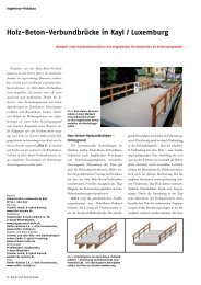
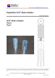
Glued-in <strong>HSK</strong> ® -<strong>Pipe</strong> <strong>Connectors</strong><br />
<strong>HSK</strong> ® -<strong>Pipe</strong> <strong>Connectors</strong><br />
Type G<br />
Type L<br />
<strong>Technical</strong> <strong>Dossier</strong> <strong>HSK</strong> ® -<strong>Pipe</strong> <strong>Connectors</strong> 2010-12<br />
<strong>Technical</strong> <strong>Dossier</strong><br />
The content of this document may only be published or distributed to external parties only with the approval of TiComTec GmbH. TiCom-<br />
Tec GmbH withdraw from any responsibilities of damages or subsequent damages resulting from the use of the information contained within<br />
this document.<br />
TiComTec GmbH, Goethestr. 60, D-63808 Haibach, Fon: +49(0)6021/44642-67, Fax: +49(0)6021/44642-68<br />
www.ticomtec.<strong>de</strong><br />
©2010 Page 1 of 22
Table of Content<br />
<strong>Technical</strong> <strong>Dossier</strong> <strong>HSK</strong> ® -<strong>Pipe</strong> <strong>Connectors</strong> 2010-12<br />
1. Basic Principles and Requirements ............................................................................................................... 3<br />
1.1 General Basic Principles ...................................................................................................................... 3<br />
1.2 Requirements for the <strong>HSK</strong> ® -<strong>Pipe</strong> <strong>Connectors</strong>...................................................................................... 3<br />
1.3 Minimum Glued-in Length .................................................................................................................. 3<br />
1.4 Dimensions of the <strong>HSK</strong> ® -<strong>Pipe</strong> <strong>Connectors</strong> .......................................................................................... 4<br />
1.5 Requirements of the Notch .................................................................................................................. 5<br />
1.6 Provisions for Implementation............................................................................................................. 5<br />
2. Outline and Design for <strong>Connectors</strong> ............................................................................................................... 6<br />
2.1 Design Concept.................................................................................................................................... 6<br />
2.1.1 General ............................................................................................................................................ 6<br />
2.1.2 Design Process ................................................................................................................................ 6<br />
2.1.3 Design Process in Accordance with EC 5 ....................................................................................... 6<br />
2.1.4 Design Values of the Impact ........................................................................................................... 6<br />
2.2 Materials Requirements ....................................................................................................................... 7<br />
2.2.1 Adhesive.......................................................................................................................................... 7<br />
2.2.2 Wood............................................................................................................................................... 7<br />
2.2.3 <strong>HSK</strong> ® -<strong>Pipe</strong> Connector ..................................................................................................................... 7<br />
2.3 Load Duration and Use Classes ........................................................................................................... 8<br />
2.3.1 Duration of Load Impact ................................................................................................................. 8<br />
2.3.2 Use Class......................................................................................................................................... 8<br />
2.3.3 Modification Coefficients kmod........................................................................................................ 8<br />
2.4 Tension in the Direction of the Rod Axis ............................................................................................ 9<br />
2.4.1 Structural Safety Evaluation............................................................................................................ 9<br />
2.4.2 Minimum Distance During Tension or Compressive Loading........................................................ 9<br />
2.4.3 Calculated Values for the Yield Strength and the Tensile Strength of Threa<strong>de</strong>d Rods................. 10<br />
2.4.4 Tensile Force Limit of Connecting Rods (Threa<strong>de</strong>d Bolts) .......................................................... 10<br />
2.4.5 Analysis of the <strong>HSK</strong> ® -<strong>Pipe</strong> Connector Type G ............................................................................. 11<br />
2.4.6 Analysis of the <strong>HSK</strong> ® -<strong>Pipe</strong> Connector Type L.............................................................................. 12<br />
2.4.7 Analysis of Strength in Net Cross Section .................................................................................... 13<br />
2.4.8 Analysis of Lateral Tension in the Base Material ......................................................................... 13<br />
2.5 Tension Perpendicular to the Rod Axis.............................................................................................. 14<br />
2.5.1 General .......................................................................................................................................... 14<br />
2.5.2 Analysis in Tension Perpendicular to Rod Axis............................................................................ 14<br />
2.6 Temperature Effect on Structural Safety............................................................................................ 16<br />
2.6.1 General .......................................................................................................................................... 16<br />
2.6.2 Requirements for the Adhesive Joint ............................................................................................ 16<br />
2.6.3 Design for Fire Emergencies......................................................................................................... 16<br />
2.7 Connection Distortion........................................................................................................................ 17<br />
2.7.1 Tension in the Direction of the Rod Axis...................................................................................... 17<br />
3. Installation Instruction for Bonding Steel Parts........................................................................................... 18<br />
3.1 General............................................................................................................................................... 18<br />
3.2 Drilling and Positioning of the <strong>HSK</strong> ® -<strong>Pipe</strong> Connector ...................................................................... 18<br />
3.3 Proceeding ......................................................................................................................................... 18<br />
4. Examples of Application ............................................................................................................................. 19<br />
5. Important Information on Liability.............................................................................................................. 20<br />
6. Attachments................................................................................................................................................. 21<br />
6.1 Literature............................................................................................................................................ 21<br />
6.2 Articles, Presentations, Reports ......................................................................................................... 21<br />
6.3 Standard, <strong>Technical</strong> Approvals/Accreditations, Recommendations .................................................. 22<br />
TiComTec GmbH, Goethestr. 60, D-63808 Haibach, Fon: +49(0)6021/44642-67, Fax: +49(0)6021/44642-68<br />
www.ticomtec.<strong>de</strong><br />
©2010 Seite 2 von 22
1. Basic Principles and Requirements<br />
1.1 General Basic Principles<br />
<strong>Technical</strong> <strong>Dossier</strong> <strong>HSK</strong> ® -<strong>Pipe</strong> <strong>Connectors</strong> 2010-12<br />
The implementation of glued-in <strong>HSK</strong> ® -<strong>Pipe</strong> Connector in load bearing woo<strong>de</strong>n construction elements<br />
requires staffs that are in charge of the equipment to be especially trained and skilled in this specific<br />
equipment. In this document, implemented tasks are based on the basic principles in accordance with<br />
DIN 1052:2008-12 and our own trials from the processes of obtaining the general technical accreditation.<br />
Furthermore, national standards and regulation must be consi<strong>de</strong>red in the <strong>de</strong>sign and implementation.<br />
1.2 Requirements for the <strong>HSK</strong> ® -<strong>Pipe</strong> <strong>Connectors</strong><br />
The <strong>de</strong>sign <strong>de</strong>tails are relevant for connectors in woo<strong>de</strong>n construction elements with glued-in steel<br />
rods. The top surface of the steel rods can either be galvanised or non-galvanised. The steel rods gra<strong>de</strong><br />
must be in accordance with the <strong>de</strong>sign specifications provi<strong>de</strong>d.<br />
1.3 Minimum Glued-in Length<br />
The glued-in length must be at least in accordance with the length of the profiled main body.<br />
TiComTec GmbH, Goethestr. 60, D-63808 Haibach, Fon: +49(0)6021/44642-67, Fax: +49(0)6021/44642-68<br />
www.ticomtec.<strong>de</strong><br />
©2010 Page 3 of 22
1.4 Dimensions of the <strong>HSK</strong> ® -<strong>Pipe</strong> <strong>Connectors</strong><br />
<strong>Technical</strong> <strong>Dossier</strong> <strong>HSK</strong> ® -<strong>Pipe</strong> <strong>Connectors</strong> 2010-12<br />
<strong>HSK</strong> ® -<strong>Pipe</strong> Connector Type G <strong>HSK</strong> ® -<strong>Pipe</strong> Connector Type L<br />
TiComTec GmbH, Goethestr. 60, D-63808 Haibach, Fon: +49(0)6021/44642-67, Fax: +49(0)6021/44642-68<br />
www.ticomtec.<strong>de</strong><br />
©2010 Seite 4 von 22
1.5 Requirements of the Notch<br />
<strong>Technical</strong> <strong>Dossier</strong> <strong>HSK</strong> ® -<strong>Pipe</strong> <strong>Connectors</strong> 2010-12<br />
The groove width adds to 5.0mm. The wood preparation should be completed just before the bonding<br />
to ensure a good adhesion between the wood and the adhesive. The notch is to be cleaned before the<br />
bonding for example with compressed air.<br />
1.6 Provisions for Implementation<br />
The installation instructions from the adhesive supplier must be followed for the bonding steel elements.<br />
If there is a connection with multiple connectors, jointed <strong>HSK</strong> ® -<strong>Pipe</strong> <strong>Connectors</strong>, which is subjected<br />
to tension on the rod axis and is connected with other components, the nuts must be tightened so<br />
that the tensile forces between each of the <strong>HSK</strong> ® -<strong>Pipe</strong> <strong>Connectors</strong> are evenly distributed.<br />
TiComTec GmbH, Goethestr. 60, D-63808 Haibach, Fon: +49(0)6021/44642-67, Fax: +49(0)6021/44642-68<br />
www.ticomtec.<strong>de</strong><br />
©2010 Page 5 of 22
2. Outline and Design for <strong>Connectors</strong><br />
2.1 Design Concept<br />
2.1.1 General<br />
<strong>Technical</strong> <strong>Dossier</strong> <strong>HSK</strong> ® -<strong>Pipe</strong> <strong>Connectors</strong> 2010-12<br />
The concept and <strong>de</strong>sign for “glued-in steel parts in load bearing timber construction elements” require<br />
special expertise of the assigned engineer.<br />
2.1.2 Design Process<br />
The information for the <strong>de</strong>sign of the connections requires advance semi-probabilistic <strong>de</strong>sign method.<br />
Therefore the limit state between the load bearing and the usability can be distinguished and for an<br />
authoritative limit state of the load bearing capacity it is multiplied with appropriate safety factors.<br />
2.1.3 Design Process in Accordance with EC 5<br />
Various European Structural Co<strong>de</strong>s take into account a semi-probabilistic <strong>de</strong>sign process in accordance<br />
to the basic principle of the EUROCODE (EC5, EC1). The DIN 1052:2008-12 is the German<br />
standard for timber structural constructions and is based from the EC5. In this section, performed<br />
specifications are based on specifications provi<strong>de</strong>d in DIN 1052:2008-12. Design method, which is<br />
based on the concept of allowable stress may not use the information provi<strong>de</strong>d in this document!<br />
2.1.4 Design Values of the Impact<br />
The <strong>de</strong>sign values for the tension “Ed” in accordance to DIN 1055-100, “Action on Structures, Part<br />
100 Basic Principles of Structural Design” provi<strong>de</strong>s:<br />
Basic Combination:<br />
Exceptional Situation:<br />
Earth Quake:<br />
TiComTec GmbH, Goethestr. 60, D-63808 Haibach, Fon: +49(0)6021/44642-67, Fax: +49(0)6021/44642-68<br />
www.ticomtec.<strong>de</strong><br />
©2010 Seite 6 von 22
2.2 Materials Requirements<br />
2.2.1 Adhesive<br />
2.2.2 Wood<br />
<strong>Technical</strong> <strong>Dossier</strong> <strong>HSK</strong> ® -<strong>Pipe</strong> <strong>Connectors</strong> 2010-12<br />
2-Components Polyurethane Adhesive (PURBOND® CR421)<br />
2-Components Epoxy Resin Adhesive (WEVO EP32S)<br />
Wood Species: Spruce and fir, laminated veneer wood.<br />
Bonding using other species of wood can only be done after consultation<br />
with the adhesive manufacturer.<br />
Strength Class: Recommen<strong>de</strong>d minimum requirements:<br />
Whole timber C24 or laminated timber GL24H<br />
Moisture Content of the Wood<br />
for Bonding: Normal case: U: ≤ 15%;<br />
When the expected equilibrium moisture content is u < 12 %, the<br />
moisture content should correspond to approximately the equilibrium<br />
moisture content when the wood is in use (~ +2, -3%)<br />
Wood Temperature for Bonding: t≥ 18°<br />
Other Basic Materials: The bonding of other basic materials is only recommen<strong>de</strong>d after consultation<br />
with TiComTec GmbH.<br />
2.2.3 <strong>HSK</strong> ® -<strong>Pipe</strong> Connector<br />
Strength Class: S235 und S355,<br />
Diameter: Outer diameter 50 mm<br />
Surface: Plain or Galvanised<br />
The surface is to be cleaned before the bonding<br />
Steel Temperature for Bonding: t≥ 18°<br />
TiComTec GmbH, Goethestr. 60, D-63808 Haibach, Fon: +49(0)6021/44642-67, Fax: +49(0)6021/44642-68<br />
www.ticomtec.<strong>de</strong><br />
©2010 Page 7 of 22
2.3 Load Duration and Use Classes<br />
2.3.1 Duration of Load Impact<br />
<strong>Technical</strong> <strong>Dossier</strong> <strong>HSK</strong> ® -<strong>Pipe</strong> <strong>Connectors</strong> 2010-12<br />
The analysis of the limit state of the load bearing capacity and the usability is distinguished each time<br />
after timed stress, “Load Duration Class”.<br />
2.3.2 Use Class<br />
The classification of a construction element in the use classes comprises of the difference in the climatic<br />
impacts. Glued-in steel rods suitable for structural elements are of use classes 1 and 2 (DIN<br />
1052:2008-12). It is recommen<strong>de</strong>d to reduce the moisture variations in the wood with glued-in <strong>HSK</strong> ® -<br />
<strong>Pipe</strong> Connector to a minimum. Cracks must be consi<strong>de</strong>red. For the application area, special requirements<br />
of the adhesive are to be especially consi<strong>de</strong>red.<br />
2.3.3 Modification Coefficients kmod<br />
Calculated values of the modification coefficients kmod for glued-in <strong>HSK</strong> ® -<strong>Pipe</strong> Connector in whole<br />
and laminated timber.<br />
Load Duration Classes<br />
Magnitu<strong>de</strong> of the Accumulated<br />
Duration of the<br />
Characteristic Load Effect<br />
Use Class (NKL)<br />
1 2 3<br />
Constant Longer than 10 years 0.60 0.60 -<br />
Long 6 months up to 10 year 0.70 0.70 -<br />
Medium 1 week up to 6 months 0.80 0.80 -<br />
Short Shorter than 1 week 0.90 0.90 -<br />
Very Short Shorter than 1 minute 1.10 1.10 -<br />
Moisture Equilibrium from the Wood Material 10 +- 5% 15 +- 5% 18 +- 6%<br />
For the adhesive PURBOND CR542 the following are to be observed:<br />
- The modification factor kmod for load duration class “constant” is to be reduced in accordance<br />
to DIN 1052:2008-12 by around 15 %.<br />
- The bonding of steel bars in larch wood is not permitted.<br />
- The bonding of steel bars is only permitted in use class 1.<br />
- The temperature of the construction elements may not exceed 50 o C.<br />
TiComTec GmbH, Goethestr. 60, D-63808 Haibach, Fon: +49(0)6021/44642-67, Fax: +49(0)6021/44642-68<br />
www.ticomtec.<strong>de</strong><br />
©2010 Seite 8 von 22
2.4 Tension in the Direction of the Rod Axis<br />
2.4.1 Structural Safety Evaluation<br />
Failure of the Steel Rod: Fax,d ≤ Rax,S,d<br />
Failure in the Adhesive Joint in the Wood: Fax,d ≤ Rax,K,d<br />
<strong>Technical</strong> <strong>Dossier</strong> <strong>HSK</strong> ® -<strong>Pipe</strong> <strong>Connectors</strong> 2010-12<br />
To ensure a ductile failure of the connection, the connections must be <strong>de</strong>signed so that the yield<br />
strength of the steel rod is reached before the failure of the adhesive joint:<br />
Rax,S,d < Rax,K,d<br />
2.4.2 Minimum Distance During Tension or Compressive Loading<br />
Perpendicular to the grain glued-in <strong>HSK</strong> ® -<strong>Pipe</strong> Connector<br />
Parallel to the grain glued-in <strong>HSK</strong> ® -<strong>Pipe</strong> Connector<br />
Individual and group arrangements<br />
Dimensions in cm<br />
TiComTec GmbH, Goethestr. 60, D-63808 Haibach, Fon: +49(0)6021/44642-67, Fax: +49(0)6021/44642-68<br />
www.ticomtec.<strong>de</strong><br />
©2010 Page 9 of 22
<strong>Technical</strong> <strong>Dossier</strong> <strong>HSK</strong> ® -<strong>Pipe</strong> <strong>Connectors</strong> 2010-12<br />
2.4.3 Calculated Values for the Yield Strength and the Tensile Strength of Threa<strong>de</strong>d<br />
Rods<br />
Yield Strength of Threa<strong>de</strong>d Rod: Rax,S,d= Aef,S x fy,b,k /1.1/ γM<br />
Tensile Strength of Screw Connections: Rax,S,d= Aef,S x fu,b,k /1.25/ γM<br />
For the <strong>de</strong>sign of the steel rods, the smaller of the two values must be taken.<br />
2.4.4 Tensile Force Limit of Connecting Rods (Threa<strong>de</strong>d Bolts)<br />
Recommen<strong>de</strong>d calculated values for the kN of each threa<strong>de</strong>d rods with metric threads<br />
Steel Rod Diameter Classification of Strengths<br />
Rated-Ø As 4.6 4.8 5.6 5.8 8.8<br />
mm mm² kN kN kN kN kN<br />
M6 20.1 3.99 5.32 4.98 6.64 10.63<br />
M8 36.6 7.26 9.68 9.07 12.10 19.36<br />
M10 58.0 11.50 15.34 14.38 19.17 30.68<br />
M12 84.3 16.72 22.29 20.90 27.87 44.59<br />
M14 116.7 23.15 30.86 28.93 38.58 61.73<br />
M16 157.0 31.14 41.52 38.93 51.90 83.04<br />
M20 245.0 48.60 64.79 60.74 80.99 129.59<br />
M24 353.0 70.02 93.36 87.52 116.69 186.71<br />
M27 459.0 91.04 121.39 113.80 151.74 242.78<br />
M30 561.0 111.27 148.36 139.09 185.45 296.73<br />
1).Rod strength class 4.6, 5.6 and BSt 500S, St500/580 shows distinct ductile behaviour<br />
2). Cross section tension of threa<strong>de</strong>d rods with metric threads<br />
TiComTec GmbH, Goethestr. 60, D-63808 Haibach, Fon: +49(0)6021/44642-67, Fax: +49(0)6021/44642-68<br />
www.ticomtec.<strong>de</strong><br />
©2010 Seite 10 von 22
2.4.5 Analysis of the <strong>HSK</strong> ® -<strong>Pipe</strong> Connector Type G<br />
The analysis is based on the buckling load tests at the MPA Wiesba<strong>de</strong>n.<br />
Load Bearing Capacity of the Steel <strong>Pipe</strong> Body:<br />
Steel Gra<strong>de</strong>: S235<br />
<strong>Technical</strong> <strong>Dossier</strong> <strong>HSK</strong> ® -<strong>Pipe</strong> <strong>Connectors</strong> 2010-12<br />
Tensile Strength Ru,k = 100.80 kN Ru,d = 91.64 kN<br />
Yield Strength Ry,k = 67.20 kN Ry,d = 61.09 kN<br />
Tensile Strength of the Wood: (Gross Cross Section)<br />
Smallest Cross Section: 80/80 mm<br />
Wood Quality: C24<br />
Use Class = 1; Load Duration Class= medium; kmod= 0.8<br />
Tensile Strength: ft,0,k= 14.0 N/mm²<br />
Load Bearing Capacity: Rt,0,k= 89.60 kN Rt,0,d= 55.14 kN<br />
Analysis of the Adhesive joint:<br />
Groove Diameter: da= 50 mm di= 45 mm<br />
Glued-in Length: lad= 100 mm<br />
Adhesive Surface: Aad= 29845 mm²<br />
Char. Adhesive Joint: fK1,k= 4.0 N/mm²<br />
Pull-out Resistance: RK1,k= 119.38 kN RK1,d= 73.46 kN<br />
Recommendation: For the use class 2, multiply the load bearing capacity of the adhesive joint<br />
with a factor of 0.85.<br />
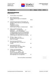
Example:<br />
Buckling Load test at the MPA Wiesba<strong>de</strong>n with a 4-parts <strong>HSK</strong> ® -<strong>Pipe</strong> Connector<br />
group Type G.<br />
Kraft [kN]<br />
500<br />
450<br />
400<br />
350<br />
300<br />
250<br />
200<br />
150<br />
100<br />
50<br />
Kraft-Verschiebungs-Diagramm<br />
Load-Shift-Diagram<br />
8.8 – Wood failure above<br />
5.6 – Screw failure above<br />
4.6 – Screw failure below<br />
0<br />
0,0 0,5 1,0 1,5 2,0 2,5 3,0 3,5 4,0<br />
Verschiebung [mm]<br />
Schrauben 4.6 unten Schrauben 5.6 oben Schrauben 8.8 unten<br />
TiComTec GmbH, Goethestr. 60, D-63808 Haibach, Fon: +49(0)6021/44642-67, Fax: +49(0)6021/44642-68<br />
www.ticomtec.<strong>de</strong><br />
©2010 Page 11 of 22
2.4.6 Analysis of the <strong>HSK</strong> ® -<strong>Pipe</strong> Connector Type L<br />
Load Bearing Capacity of the Steel Body:<br />
Steel Gra<strong>de</strong>: S355<br />
Tensile Strength Ru,k = 76.50 kN Ru,d = 69.55 kN<br />
Yield Strength Ry,k = 54.00 kN Ry,d = 49.00 kN<br />
Load Bearing Capacity of the Wood: (Gross Cross Section)<br />
Smaller Cross Section: 80/80 mm<br />
Wood Quality: C24<br />
Use Class= 1: Load Duration Class= medium; kmod= 0.8<br />
Tensile Strength: ft,0,k= 14.0 N/mm²<br />
Load Bearing Capacity Rt,0,k= 89.60 kN Rt,0,d= 55.14 kN<br />
Analysis of the Adhesive Joint:<br />
Groove Diameter: da= 50 mm di= 45 mm<br />
Glued-in Length: lad= 100 mm<br />
Adhesive Surface: Aad= 29845 mm²<br />
Char. Adhesive Joint Strength: fK1,k= 4.0 N/mm²<br />
<strong>Technical</strong> <strong>Dossier</strong> <strong>HSK</strong> ® -<strong>Pipe</strong> <strong>Connectors</strong> 2010-12<br />
Pull-out Resistance: RK1,k= 119.38 kN RK1,d= 73.47 kN<br />
Analysis of the Adhesive Anchors:<br />
Char. Adhesive Dowel Strength in nh= 6 Anchor Rows: fKDü,k= 1.30 kN<br />
Number of Adhesive Dowel: neff = 6 x 2 x 4 = 48 Adhesive Dowel<br />
RKDü,k= 48 x 1,30 kN = 62.40 kN<br />
RKDü,d= 62.4 kN x 0,615 = 38,40 kN<br />
Recommendation:<br />
For the use class 2 multiply the load bearing capacity of the adhesive joint with a factor of 0.85.<br />
Numerous tests at the MPA Wiesba<strong>de</strong>n have confirmed the strength values for the adhesive dowels.<br />
TiComTec GmbH, Goethestr. 60, D-63808 Haibach, Fon: +49(0)6021/44642-67, Fax: +49(0)6021/44642-68<br />
www.ticomtec.<strong>de</strong><br />
©2010 Seite 12 von 22
2.4.7 Analysis of Strength in Net Cross Section<br />
<strong>Technical</strong> <strong>Dossier</strong> <strong>HSK</strong> ® -<strong>Pipe</strong> <strong>Connectors</strong> 2010-12<br />
Recommendation:<br />
As the smallest woo<strong>de</strong>n cross section it is recommen<strong>de</strong>d for a square cross section with b x h = 80 x<br />
80 mm 2 , accordingly to 6400 mm 2 , or a round cross section with a diameter from d = 80mm, accordingly<br />
5026 mm 2 . The failure surface of a <strong>HSK</strong> ® -<strong>Pipe</strong> Connector is 371mm 2 . The largest cross section<br />
weakening is thus:<br />
Square Cross Section ηQ= 371/6400 = 0.06<br />
Round Cross Section ηR= 371/5026 = 0.07<br />
To be on the safe si<strong>de</strong> and to account for the influence of the cross section weakening, the load bearing<br />
capacity of the rated wood can be multiplied with a factor<br />
ηN= 0.90<br />
2.4.8 Analysis of Lateral Tension in the Base Material<br />
In tensile load perpendicular to the wood grain, an analysis of the base material is to be conducted if<br />
the glued-in length is less than 0.7 of the component height.<br />
TiComTec GmbH, Goethestr. 60, D-63808 Haibach, Fon: +49(0)6021/44642-67, Fax: +49(0)6021/44642-68<br />
www.ticomtec.<strong>de</strong><br />
©2010 Page 13 of 22
2.5 Tension Perpendicular to the Rod Axis<br />
2.5.1 General<br />
<strong>Technical</strong> <strong>Dossier</strong> <strong>HSK</strong> ® -<strong>Pipe</strong> <strong>Connectors</strong> 2010-12<br />
Glued-in <strong>HSK</strong> ® -<strong>Pipe</strong> Connector with an applied load perpendicular to the rod axis can be measured as<br />
for conventional dowel pin, especially of Type A1/B1 (Apple Dowel). The following factors have an<br />
influence on the load bearing capacity perpendicular to the rod axis:<br />
- Diameter of the <strong>HSK</strong> ® -<strong>Pipe</strong> Connector<br />
- Thickness and Steel Gra<strong>de</strong> of the Connector Parts<br />
- Angle of the Load Tension/Wood Grain<br />
- Compliance with the Minimum Distance<br />
- Wood Qualities (C 24, GL24 ...)<br />
- Bulk Density<br />
- Use Class of the Construction Components (Use Class 1)<br />
- Load Duration Class of the Tension (Load Duration Class = Medium)<br />
The <strong>de</strong>sign is carried out according to all applicable national standards or appropriate application<br />
document.<br />
2.5.2 Analysis in Tension Perpendicular to Rod Axis<br />
Failure in the Steel Components: FV,d ≤ RV,S,d<br />
Failure in the Wood: FV,d ≤ RV,d<br />
The Shearing Limit Va,R,d of a Threa<strong>de</strong>d Bolt M16 is:<br />
Strength Class Shearing Limit Va,R,d [kN]<br />
4.6 43.9<br />
5.6 54.8<br />
8.8 87.7<br />
Dowel Type A1/B1 (Apple-Dowel) is so rigid that the available power is almost completely transferred<br />
from the dowel. This theory can also be applied to the <strong>HSK</strong> ® -<strong>Pipe</strong> Connector. The characteristic<br />
load bearing capacity of a <strong>HSK</strong> ® -<strong>Pipe</strong> Connector with d<strong>HSK</strong>= 50 mm in the grain direction can be<br />
calculated with the following equation:<br />
Rj,0,k= 0.035 x d<strong>HSK</strong> 1,5<br />
TiComTec GmbH, Goethestr. 60, D-63808 Haibach, Fon: +49(0)6021/44642-67, Fax: +49(0)6021/44642-68<br />
www.ticomtec.<strong>de</strong><br />
©2010 Seite 14 von 22
<strong>Technical</strong> <strong>Dossier</strong> <strong>HSK</strong> ® -<strong>Pipe</strong> <strong>Connectors</strong> 2010-12<br />
Minimum values of the characteristic load bearing capacity of wood perpendicular to the rod axis un<strong>de</strong>r<br />
consi<strong>de</strong>ration of the following terms:<br />
Load-Grain Angle α<br />
<strong>HSK</strong> ® -<strong>Pipe</strong> Connector Ø50 mm<br />
Char. Load Resistance in Tension Perpendicular to Grain (kN)<br />
° Ø 50<br />
0 12.37<br />
15 12.08<br />
30 11.33<br />
45 10.47<br />
60 9.71<br />
75 9.23<br />
90 9.07<br />
For simultaneous load from shear and pull the combined analysis is conducted in accordance to the<br />
following equation:<br />
(FV,d / RV,d) 2 + (Fax,d / Rax,d) 2 ≤ 1<br />
TiComTec GmbH, Goethestr. 60, D-63808 Haibach, Fon: +49(0)6021/44642-67, Fax: +49(0)6021/44642-68<br />
www.ticomtec.<strong>de</strong><br />
©2010 Page 15 of 22
2.6 Temperature Effect on Structural Safety<br />
2.6.1 General<br />
<strong>Technical</strong> <strong>Dossier</strong> <strong>HSK</strong> ® -<strong>Pipe</strong> <strong>Connectors</strong> 2010-12<br />
The <strong>de</strong>sign of load bearing structures for fire emergencies is to take into account the countries or project<br />
specific requirements.<br />
2.6.2 Requirements for the Adhesive Joint<br />
Connections that are used for load bearing structure of existential important must be calculated in accordance<br />
to the requirements for fire emergencies. The necessary strength of the adhesive joint in<br />
glued-in steel rods is analysed with:<br />
PURBOND ® CR421 up to 50°C<br />
and<br />
WEVO EP32S up to 60 °C.<br />
Preliminary tests at the MPA Wiesba<strong>de</strong>n have shown that the temperature level can also be carried by<br />
glued-in <strong>HSK</strong> ® -<strong>Pipe</strong> Connector.<br />
2.6.3 Design for Fire Emergencies<br />
The ISO-Standard Temperature Curve (ISO-Standard 834) shows a temperature difference of ∆T<br />
822°C after 30 minutes of fire exposure in fire room.<br />
For a period after 60 minutes, the temperature difference from ∆T 925°C is shown.<br />
If there is a request for the structure or the connection to have a fire resistance class F30B (R30) or<br />
F60B (R60), then necessary measures must be taken to ensure that the adhesive-specific temperature<br />
in the adhesive joints and in the steel rods is not excee<strong>de</strong>d.<br />
Furthermore it should be noted that the heat of the steel parts lying on the surface can be transferred to<br />
the steel parts lying on the insi<strong>de</strong>.<br />
Up to an adhesive joint temperature of 45 o C a higher plastic shift occurred.<br />
TiComTec GmbH, Goethestr. 60, D-63808 Haibach, Fon: +49(0)6021/44642-67, Fax: +49(0)6021/44642-68<br />
www.ticomtec.<strong>de</strong><br />
©2010 Seite 16 von 22
2.7 Connection Distortion<br />
2.7.1 Tension in the Direction of the Rod Axis<br />
<strong>Technical</strong> <strong>Dossier</strong> <strong>HSK</strong> ® -<strong>Pipe</strong> <strong>Connectors</strong> 2010-12<br />
During an initial load effect until the complete power transfer effect, a plastic shift (slip) occurred. The<br />
information below is based on tests at the CTBA in Bor<strong>de</strong>aux with steel rods of Ø 16mm.<br />
Slip per Steel Rod: w≤ 215 kN/mm<br />
Shifting Module (Medium Values): Kser= 215 kN/mm<br />
Shifting Module (5%-Percentile Values): Kser,5%= 179 kN/mm<br />
TiComTec GmbH, Goethestr. 60, D-63808 Haibach, Fon: +49(0)6021/44642-67, Fax: +49(0)6021/44642-68<br />
www.ticomtec.<strong>de</strong><br />
©2010 Page 17 of 22
3. Installation Instruction for Bonding Steel Parts<br />
3.1 General<br />
<strong>Technical</strong> <strong>Dossier</strong> <strong>HSK</strong> ® -<strong>Pipe</strong> <strong>Connectors</strong> 2010-12<br />
The provisions provi<strong>de</strong>d by the adhesive manufacturers are to be followed in each case. Requirements<br />
during adhesion process to achieve maximum strength:<br />
Room Temperature: ≥ 20°C<br />
Material Temperature (Wood and Steel): ≥ 18°C<br />
Wood Moistness: ≤ 15%<br />
Connections which can cause structural failure of the load bearing construction elements are to be<br />
prepared with special care. The basic parameters must be comprehensively documented with an installation<br />
protocol. Additionally, it is recommen<strong>de</strong>d after agreement with the responsible engineer, to<br />
prepare a corresponding reference block or test specimen and to test the failure load until a fracture is<br />
<strong>de</strong>termine.<br />
3.2 Drilling and Positioning of the <strong>HSK</strong> ® -<strong>Pipe</strong> Connector<br />
The drill-hole in the base material is to be created with special equipment. In positioning the <strong>HSK</strong> ® -<br />
<strong>Pipe</strong> Connector, it is to ensure that the rod is fully covered with adhesive in the base material.<br />
3.3 Proceeding<br />
1. Verify the wood humidity, room and surrounding temperature<br />
2. Compare the steel rod quality with the <strong>de</strong>sign specifications<br />
3. Make the holes for the steel rod and ventilation openings<br />
4. Clean the holes with compressed air and <strong>de</strong>grease the steel parts<br />
5. Bring and position the <strong>HSK</strong> ® -<strong>Pipe</strong> Connector<br />
6. Prepare the adhesive cartouche and the dispensing equipments<br />
7. Inject the adhesive<br />
8. Write installation report/protocol<br />
9. Wait for har<strong>de</strong>ning<br />
10. Muster evenly the tightening torque of the parent compounds<br />
TiComTec GmbH, Goethestr. 60, D-63808 Haibach, Fon: +49(0)6021/44642-67, Fax: +49(0)6021/44642-68<br />
www.ticomtec.<strong>de</strong><br />
©2010 Seite 18 von 22
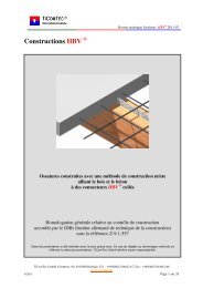
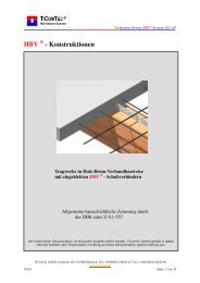
4. Examples of Application<br />
<strong>Technical</strong> <strong>Dossier</strong> <strong>HSK</strong> ® -<strong>Pipe</strong> <strong>Connectors</strong> 2010-12<br />
Joints for timber frame construction<br />
Built-in reinforcement<br />
Fastening points in plywood board for<br />
dynamic tests.<br />
Tension points for adhesive joints<br />
TiComTec GmbH, Goethestr. 60, D-63808 Haibach, Fon: +49(0)6021/44642-67, Fax: +49(0)6021/44642-68<br />
www.ticomtec.<strong>de</strong><br />
©2010 Page 19 of 22
5. Important Information on Liability<br />
<strong>Technical</strong> <strong>Dossier</strong> <strong>HSK</strong> ® -<strong>Pipe</strong> <strong>Connectors</strong> 2010-12<br />
This publication has been ma<strong>de</strong> with great care and accuracy. All information contained in here, information<br />
and references are based on basic principles, formulas and safety provisions pursuant to the<br />
technical instructions, operation and installation processes and further documentations of the TiCom-<br />
Tec GmbH, which are correct at the time of production. All information and values contained here are<br />
of average values after laboratory tests and other control terms and conditions.<br />
The user is automatically accountable for the appropriateness of the data un<strong>de</strong>r consi<strong>de</strong>ration of the<br />
terms and conditions of the application and inspection of relevant products.<br />
The user has to test, if the mentioned requirements and criteria are effective and conform to the building<br />
site. TiComTec GmbH can provi<strong>de</strong> general instructions and advice for the selection of the right<br />
products for a special application and can therefore produce the conforming instructions for application<br />
but the customer/user is solely accountable.<br />
All products are in strict conformity with all actual instructions, which are to be released with application<br />
and written consent of TiComTec GmbH. The shipment of products and the consultation are to be<br />
carried out in general by the terms and conditions of TiComTec GmbH. TiComTec GmbH strives to<br />
in<strong>de</strong>pen<strong>de</strong>ntly further <strong>de</strong>velop its productivity. Therefore we hold the rights to instructions; specifications<br />
etc. and have the right to make changes without notification.<br />
TiComTec GmbH takes no responsibility for indirect or direct <strong>de</strong>fect or consequential damage, casualties<br />
or costs in relation to the application or because of the impracticality of application for anyone<br />
inten<strong>de</strong>d purpose. By implication, authorised representations for the application or the applicability for<br />
a specific purpose shall be explicitly exclu<strong>de</strong>d.<br />
TiComTec GmbH, Goethestr. 60, D-63808 Haibach, Fon: +49(0)6021/44642-67, Fax: +49(0)6021/44642-68<br />
www.ticomtec.<strong>de</strong><br />
©2010 Seite 20 von 22
6. Attachments<br />
6.1 Literature<br />
<strong>Technical</strong> <strong>Dossier</strong> <strong>HSK</strong> ® -<strong>Pipe</strong> <strong>Connectors</strong> 2010-12<br />
[1] François Colling: Holzbau - Grundlagen und Bemessungshilfen. 2.Auflage,<br />
Vieweg+Teubner, 2008, ISBN 978-3-8348-0259-0<br />
[2] François Colling: Holzbau – Beispiele. 2.Auflage,<br />
Vieweg+Teubner, 2008, ISBN 978-3-8348-0258-3<br />
[3] För<strong>de</strong>rgesellschaft Holzbau und Ausbau GmbH: DIN 1052 Praxishandbuch Holzbau 2. überarbeitete<br />
Auflage, Beuth Verlag GmbH , 2010, ISBN 978-3-410-17176-8<br />
[4] Schnei<strong>de</strong>r K.-J.: Bautabellen für Ingenieure. 18.Auflage,<br />
Werner Verlag, 2008, ISBN 978-3-8041-5236-6<br />
[5] Helmuth Neuhaus: Ingenieurholzbau. 2.Auflage,<br />
Vieweg+Teubner, 2009, ISBN 978-3-519-15248-4<br />
6.2 Articles, Presentations, Reports<br />
[6] Bahmer, R.; Bathon, L. (2003): „Mut zu Neuem – 10 m frei spannen<strong>de</strong> Holz-Beton-Verbund-<br />
Flach<strong>de</strong>cke“, Bauen mit Holz, Bru<strong>de</strong>rverlag, Karlsruhe, 3/2003, Seite 21 – 25<br />
[7] Pörtner, Dr.-Ing. Carsten (2006): Untersuchungen zum Verbund zwischen eingeklebten stiftförmigen<br />
faserverstärkten Kunststoffen und Holz, Schriftenreihe Bauwerkserhaltung und<br />
Holzbau, UNI Kassel, ISBN-13: 978-3-89958-191-1<br />
[8] Bathon, L.; Bletz, O.; Schmidt, J. (2006): „Untersuchungsbericht Nr. 113-06 zur Tragfähigkeit<br />
von PUR-Klebstoffen unter Temperatureinfluss“, Fachhochschule Wiesba<strong>de</strong>n, Holzbaulabor<br />
[9] Bathon, L.; Bletz, O. (2008): „In Holz eingeklebte Verbindungsmittel aus Metall“, die neue<br />
quadriga 2/2008, Seite 13 - 18<br />
[10] Gehri, E.: (2009) Eingeklebte Anker – Anfor<strong>de</strong>rungen und Umsetzungen<br />
IHF 2009, Garmisch-Partenkirschen, Band 1<br />
[11] Bathon, L.; Bletz-Mühldorfer, O.; Schmidt, J.; Weber, M.; Weil, M. (2010) „Zur Temperaturbeständigkeit<br />
und Ermüdungsfestigkeit von in Holz eingeklebten Gewin<strong>de</strong>stangen und Lochblechen“,<br />
die neue quadriga 2/2010, Seite 45 - 49<br />
[12] Bahmer, R.: (2010): Geklebte Stahl/Holz/Verbindungen – starre Verbindung mit geringer<br />
Querschnittsschwächung, Tagungsband 1. Internationale Holzbrückentage IHB 2010, Bad<br />
Wörishofen<br />
TiComTec GmbH, Goethestr. 60, D-63808 Haibach, Fon: +49(0)6021/44642-67, Fax: +49(0)6021/44642-68<br />
www.ticomtec.<strong>de</strong><br />
©2010 Page 21 of 22
<strong>Technical</strong> <strong>Dossier</strong> <strong>HSK</strong> ® -<strong>Pipe</strong> <strong>Connectors</strong> 2010-12<br />
6.3 Standard, <strong>Technical</strong> Approvals/Accreditations, Recommendations<br />
[12] Standard DIN 1052:2008-12: Concept, Calculation and Design for Timber Constructions –<br />
general <strong>de</strong>sign rules and <strong>de</strong>sign rules for building construction.<br />
Berlin: Beuth Verlag GmbH<br />
[13] General Building Authority Accreditation: Z-9.1-557. Wood-Concrete-Composite Systems<br />
with glued-in HBV-Shear <strong>Connectors</strong>. Valid until 04.07.2015<br />
TiComTec GmbH, D-63808 Haibach<br />
[14] General Building Authority Accreditation: Z-9.1-705.<br />
2K-EP Adhesive WEVO-Special Resin EP32S with WEVO-Accelerator B 22 TS<br />
For bonding steel rods into woo<strong>de</strong>n materials valid until 31.01.2014<br />
WEVO-CHEMIE GmbH, D-73760 Ostfol<strong>de</strong>rn-Kemnat<br />
[15] General Building Authority Accreditation: Z-9.1-707.<br />
2K-PUR-Adhesive PURBOND ® CR421 for bonding steel rods into woo<strong>de</strong>n materials valid<br />
until 31.05.2015<br />
PURBOND AG, CH-6203 Sempach-Station<br />
TiComTec GmbH, Goethestr. 60, D-63808 Haibach, Fon: +49(0)6021/44642-67, Fax: +49(0)6021/44642-68<br />
www.ticomtec.<strong>de</strong><br />
©2010 Seite 22 von 22