A Text Book on Engineering Graphics - Central Board of Secondary ...
A Text Book on Engineering Graphics - Central Board of Secondary ... A Text Book on Engineering Graphics - Central Board of Secondary ...
2.15.1 TYPES OF SUNK KEYS 2.15.1.1 RECTANGULAR TAPER KEY W A sunk key is designated by its width x thickness x length. (w x T x L) see fig 2.55 Sunk keys means, half of the thickness (0.5T) (measured at the side not on centre line) k within the key seat and the other half thickness (0.5T) is within the keyway (see fig 2.57). There are different types of sunk keys viz. (i) rectangular taper key (ii) woodruff key (iii) double head feather key Let us now learn how to draw the views of these sunk keys. MACHINE DRAWING Rectangular sunk taper key is of rectangular cross section, with the thickness not uniform throughout the length of the key. See fig 2.56 L TAPER 1 IN 100 (i) RECTANGULAR TAPER KEY Fig 2.56 Drawing proportions for a rectangular taper key are as follows. Let 'D' be the diameter of the shaft, then width of the key, W=D/4 Thickness of the key, T=D/6 T Length=1.5D to 2D, Taper = 1 in 100 T W FRONT VIEW The taper key prevent relative rotational as well as axial movement between the two mating piece. Generally, the upper surface of the key is tapered and hence the keyway is also correspondingly tapered. The tapered end is hammered to remove the key from the joint. 82 ENGINEERING GRAPHICS L TOP VIEW VIEWS OF A RECTANGULAR TAPER KEY W L RECTANGULAR SUNK KEY Fig 2.55 SIDE VIEW T
MACHINE DRAWING Example 24: Solution 2.15.1.2 WOODRUFF KEY Sketch free hand a rectangular taper key, in position, on a shaft of diameter 40mm, keeping the axis of the shaft parallel to V.P and H.P, showing upper half sectional front elevation. Give standard dimensions. Refer Fig 2.57 2D 1.5D D L PARALLEL TO AXIS FRONT VIEW 40 W= D 4 TAPER 1 IN 100 ØD T= D 6 10 6.7 60 Fig 2.57 Woodruff key is a special sunk key. It looks like a segment of a circular disc. The key seat is semi circular in shape but the keyway is rectangular. The keyway is smaller in size than the key seat. The advantage of woodruff key is that it can be easily adjusted in the recess. It is largely used in machine tools and automobile work. ENGINEERING GRAPHICS 83 1.5D 2D 80 W LEFT SIDE VIEW RECTANGULAR TAPER KEY IN POSITION WOODRUFF KEY WOODRUFF KEY WITH KEY SLOT IN SHAFT Fig 2.58 0.5T 0.5T
- Page 39 and 40: ISOMETRIC PROJECTION Steps: Exmple
- Page 41 and 42: ISOMETRIC PROJECTION Steps: 1. Draw
- Page 43 and 44: ISOMETRIC PROJECTION Steps: 1. Draw
- Page 45 and 46: ISOMETRIC PROJECTION 7. BELOW: CIRC
- Page 47 and 48: ISOMETRIC PROJECTION 30 66 30 15. B
- Page 49 and 50: MACHINE DRAWING Fig 2.1 b : Screw t
- Page 51 and 52: MACHINE DRAWING (v) RIGHT HAND AND
- Page 53 and 54: MACHINE DRAWING 2.4 STANDARD PROFIL
- Page 55 and 56: MACHINE DRAWING 2.4.2 METRIC THREAD
- Page 57 and 58: MACHINE DRAWING Steps involved are
- Page 59 and 60: MACHINE DRAWING 2.5 BOLTS In day to
- Page 61 and 62: MACHINE DRAWING (vii) The end of th
- Page 63 and 64: MACHINE DRAWING 2.5.3 T-BOLT Exampl
- Page 65 and 66: MACHINE DRAWING Steps Involved Exer
- Page 67 and 68: MACHINE DRAWING Example 10 : Soluti
- Page 69 and 70: MACHINE DRAWING 2.6.2 SQUARE NUTS E
- Page 71 and 72: MACHINE DRAWING Solution : Steps In
- Page 73 and 74: MACHINE DRAWING Steps Involved Exam
- Page 75 and 76: MACHINE DRAWING Example 15: Solutio
- Page 79 and 80: MACHINE DRAWING 2.10 INTRODUCTION F
- Page 81 and 82: MACHINE DRAWING 2.11.3CONVENTIONAL
- Page 83 and 84: MACHINE DRAWING Example 18: Solutio
- Page 85 and 86: MACHINE DRAWING Example 20: Solutio
- Page 87 and 88: MACHINE DRAWING Exercises NOTE: Ass
- Page 89: MACHINE DRAWING Example 24: Solutio
- Page 93 and 94: MACHINE DRAWING 2.15.1.3 DOUBLE HEA
- Page 95 and 96: 3 CHAPTER All of you have seen a bi
- Page 97 and 98: BEARINGS 3. Plummer Block or Pedest
- Page 99 and 100: BEARINGS Answer of Fig. 3.3 10 20 2
- Page 101 and 102: BEARINGS Question: The figure given
- Page 103 and 104: BEARINGS R5 R6 2 HOLES FOR BOLTS 24
- Page 105 and 106: A BEARINGS Answer of fig 3.12 20 40
- Page 107 and 108: BEARINGS NOTE : As per our syllabus
- Page 109 and 110: BEARINGS Question: The figure given
- Page 111 and 112: BEARINGS EXPLODED VIEW OF A FOOT ST
- Page 113 and 114: BEARINGS 5 15 15 40 15 15 ENGINEERI
- Page 115 and 116: BEARINGS FOOT STEP BEARING Ø 120
- Page 117 and 118: ROD JOINTS DIMENSIONS OF A COTTER:
- Page 119 and 120: ROD JOINTS SLEEVE AND COTTER JOINT:
- Page 121 and 122: ROD JOINTS Solution of fig : 4.5 Qu
- Page 123 and 124: ROD JOINTS Answer of fig. 4.9 50 50
- Page 125 and 126: ROD JOINTS Question: The details of
- Page 127 and 128: ROD JOINTS Exercise: The three view
- Page 129 and 130: ROD JOINTS KNUCKLE JOINT OR PIN JOI
- Page 131 and 132: ROD JOINTS Question: fig 4.19(a) sh
- Page 133 and 134: ROD JOINTS Question: The figure 4.2
- Page 135 and 136: ROD JOINTS Exercises: The three vie
- Page 137 and 138: ROD JOINTS Dimensions of a Gib and
- Page 139 and 140: ROD JOINTS 96 66 12 GIB 26 COTTER T
2.15.1 TYPES OF SUNK KEYS<br />
2.15.1.1 RECTANGULAR TAPER KEY<br />
W<br />
A sunk key is designated by its width x thickness x<br />
length. (w x T x L) see fig 2.55<br />
Sunk keys means, half <strong>of</strong> the thickness (0.5T)<br />
(measured at the side not <strong>on</strong> centre line) k within the<br />
key seat and the other half thickness (0.5T) is within<br />
the keyway (see fig 2.57). There are different types<br />
<strong>of</strong> sunk keys viz.<br />
(i) rectangular taper key<br />
(ii) woodruff key<br />
(iii) double head feather key<br />
Let us now learn how to draw the views <strong>of</strong> these sunk keys.<br />
MACHINE DRAWING<br />
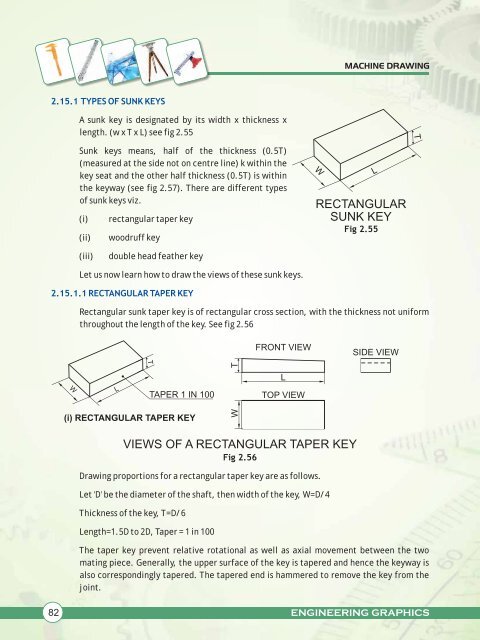
Rectangular sunk taper key is <strong>of</strong> rectangular cross secti<strong>on</strong>, with the thickness not uniform<br />
throughout the length <strong>of</strong> the key. See fig 2.56<br />
L<br />
TAPER 1 IN 100<br />
(i) RECTANGULAR TAPER KEY<br />
Fig 2.56<br />
Drawing proporti<strong>on</strong>s for a rectangular taper key are as follows.<br />
Let 'D' be the diameter <strong>of</strong> the shaft, then width <strong>of</strong> the key, W=D/4<br />
Thickness <strong>of</strong> the key, T=D/6<br />
T<br />
Length=1.5D to 2D, Taper = 1 in 100<br />
T<br />
W<br />
FRONT VIEW<br />
The taper key prevent relative rotati<strong>on</strong>al as well as axial movement between the two<br />
mating piece. Generally, the upper surface <strong>of</strong> the key is tapered and hence the keyway is<br />
also corresp<strong>on</strong>dingly tapered. The tapered end is hammered to remove the key from the<br />
joint.<br />
82 ENGINEERING GRAPHICS<br />
L<br />
TOP VIEW<br />
VIEWS OF A RECTANGULAR TAPER KEY<br />
W<br />
L<br />
RECTANGULAR<br />
SUNK KEY<br />
Fig 2.55<br />
SIDE VIEW<br />
T


