A Text Book on Engineering Graphics - Central Board of Secondary ...
A Text Book on Engineering Graphics - Central Board of Secondary ...
A Text Book on Engineering Graphics - Central Board of Secondary ...

You also want an ePaper? Increase the reach of your titles
YUMPU automatically turns print PDFs into web optimized ePapers that Google loves.
6.1.1.1 Features:<br />
152<br />
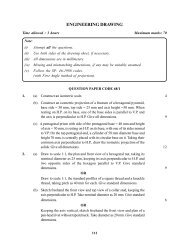
SHAFT COUPLINGS<br />
The Unprotected Flange Coupling has two similar cast ir<strong>on</strong> flanges, ( left & right ) with the<br />
shape similar to the flanges in the 'flanged pipe joint'. But these flanges have keyways in<br />
the hubs, so that the ends <strong>of</strong> the shafts to be c<strong>on</strong>nected can be keyed to the flanges with<br />
separate rectangular sunk type keys. Even the shafts also have keyways, which are<br />
assembled at right angles, so that the key <strong>of</strong> <strong>on</strong>e shaft does not slide into the other. These<br />
keys are usually driven from inside faces <strong>of</strong> the flanges for easy fitting.<br />
KEY WAY<br />
(Hub <strong>of</strong><br />
Flange)<br />
SHAFT (M.S.)<br />
4 HOLES<br />
KEY WAY (Shaft)<br />
KEY (M.S.) (2-OFF)<br />
(Rectangular Sunk-Taper)<br />
LEFT - FLANGE (C.I)<br />
4 holes to accomodate<br />
4 Bolts & Nuts<br />
Fig 6.4<br />
KEY WAY<br />
(Flange)<br />
SHAFT (M.S.)<br />
KEY WAY (Shaft)<br />
RIGHT<br />
FLANGE (C.I.)<br />
HEX. BOLT & NUT<br />
4-OFF<br />
DETAILS OF AN UNPROTECTED FLANGE COUPLING<br />
(HALF SEC. PICTORIAL VIEW)<br />
Here also, the faces <strong>of</strong> the flanges are kept at right angles to the axis for proper alignment.<br />
Now, to get the perfect alignment <strong>of</strong> shafts, <strong>on</strong>e <strong>of</strong> the flanges may have a projected<br />
circular extensi<strong>on</strong> <strong>on</strong> the outside and thus the other flange will, have a corresp<strong>on</strong>ding slot<br />
/ recess. This gives the flanges a perfect fit and this kind <strong>of</strong> arrangement being similar to<br />
the spigot and socket joint, is termed as 'spigot and socket centring'. There may also be<br />
some clearance (gap) between this kind <strong>of</strong> fit, to adjust the shaft.<br />
The faces <strong>of</strong> the two flanges are then held together with the help <strong>of</strong> bolts and nuts (4 or<br />
more ). These may be square headed or hexag<strong>on</strong>al headed. The bolts should be an exact<br />
fit, so that the power can be transmitted properly from <strong>on</strong>e shaft and flange to another.<br />
ENGINEERING GRAPHICS