A Text Book on Engineering Graphics - Central Board of Secondary ...
A Text Book on Engineering Graphics - Central Board of Secondary ...
A Text Book on Engineering Graphics - Central Board of Secondary ...

You also want an ePaper? Increase the reach of your titles
YUMPU automatically turns print PDFs into web optimized ePapers that Google loves.
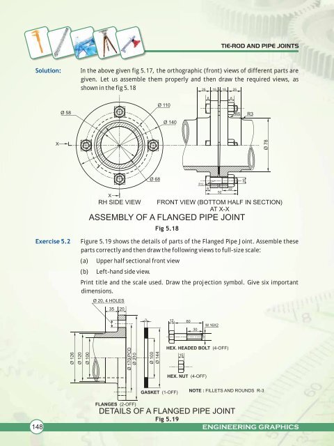
Soluti<strong>on</strong>:<br />
Exercise 5.2<br />
148<br />
X<br />
Ø 58<br />
Ø 126<br />
Ø 120<br />
Ø 100<br />
TIE-ROD AND PIPE JOINTS<br />
In the above given fig 5.17, the orthographic (fr<strong>on</strong>t) views <strong>of</strong> different parts are<br />
given. Let us assemble them properly and then draw the required views, as<br />
shown in the fig 5.18<br />
X<br />
Ø 68<br />
Ø 110<br />
Ø 140<br />
ASSEMBLY OF A FLANGED PIPE JOINT<br />
Fig 5.18<br />
Figure 5.19 shows the details <strong>of</strong> parts <strong>of</strong> the Flanged Pipe Joint. Assemble these<br />
parts correctly and then draw the following views to full-size scale:<br />
(a) Upper half secti<strong>on</strong>al fr<strong>on</strong>t view<br />
(b) Left-hand side view.<br />
Print title and the scale used. Draw the projecti<strong>on</strong> symbol. Give six important<br />
dimensi<strong>on</strong>s.<br />
DETAILS OF A FLANGED PIPE JOINT<br />
Fig 5.19<br />
R12<br />
25 15 3 15 25<br />
6 8<br />
6 22<br />
52<br />
RH SIDE VIEW FRONT VIEW (BOTTOM HALF IN SECTION)<br />
AT X-X<br />
Ø 20, 4 HOLES<br />
35 20<br />
Ø 170 PCD<br />
Ø 210<br />
FLANGES (2-OFF)<br />
3<br />
Ø 100<br />
Ø 144<br />
GASKET (1-OFF)<br />
12 60<br />
HEX. HEADED BOLT (4-OFF)<br />
15<br />
30<br />
HEX. NUT (4-OFF)<br />
M 16X2<br />
R5<br />
M8<br />
R3<br />
NOTE : FILLETS AND ROUNDS R-3<br />
Ø 78<br />
ENGINEERING GRAPHICS