A Text Book on Engineering Graphics - Central Board of Secondary ...
A Text Book on Engineering Graphics - Central Board of Secondary ...
A Text Book on Engineering Graphics - Central Board of Secondary ...

Create successful ePaper yourself
Turn your PDF publications into a flip-book with our unique Google optimized e-Paper software.
146<br />
42 20<br />
M 10<br />
(THREADED<br />
LENGTH = 20)<br />
10 12 3 12<br />
R20<br />
8<br />
R3<br />
TOP HALF SEC. FRONT VIEW<br />
Ø 132<br />
Ø 74<br />
SCALE 1:1<br />
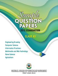
ASSEMBLY OF A FLANGED PIPE JOINT<br />
Fig 5.16<br />
TIE-ROD AND PIPE JOINTS<br />
2. Then, the four square (SQ) headed bolts are fitted in the holes as shown in the<br />
flanges centrally; the distance between the axes <strong>of</strong> holes being Ø106 (PCD). (It<br />
can be seen, the holes are <strong>of</strong> Ø12 and the bolts & nuts have diameter 10mm, so a<br />
gap (clearance) <strong>of</strong> 1mm is present around and is shown in the top and bottom <strong>of</strong><br />
the shank <strong>of</strong> the bolt, placed in the holes, in the fr<strong>on</strong>t view.) Refer Fig 5.16.<br />
3. Since, secti<strong>on</strong>al fr<strong>on</strong>t view (upper half in secti<strong>on</strong>) is asked, so both the flanged<br />
pipes are secti<strong>on</strong>ed in opposite directi<strong>on</strong>s, as they are different machine parts.<br />
The gasket, being a thin secti<strong>on</strong>, may be shown entirely black as per SP-46 :<br />
(2003) BIS specificati<strong>on</strong>s (10.2.3). Notice the cross-secti<strong>on</strong> <strong>of</strong> the pipe (to<br />
represent a hollow cylindrical secti<strong>on</strong>.)<br />
4. In the side view, which is a complete view, all the bolts and nuts (bolt head in<br />
hidden lines) are shown <strong>on</strong> the ring <strong>of</strong> diameter 106, i.e. PCD (pitch circle<br />
diameter).<br />
A<br />
LH SIDE VIEW<br />
4 HOLES Ø 12<br />
ON PCD = 106<br />
Ø 90<br />
Ø 80<br />
Ø 62<br />
ENGINEERING GRAPHICS<br />
A