A Text Book on Engineering Graphics - Central Board of Secondary ...
A Text Book on Engineering Graphics - Central Board of Secondary ...
A Text Book on Engineering Graphics - Central Board of Secondary ...

You also want an ePaper? Increase the reach of your titles
YUMPU automatically turns print PDFs into web optimized ePapers that Google loves.
Soluti<strong>on</strong>s:<br />
138<br />
Ø 25<br />
Point to remember :<br />
20 10<br />
150<br />
22 14<br />
14<br />
Fig 5.5<br />
10 20<br />
TIE-ROD AND PIPE JOINTS<br />
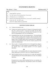
The above fig 5.5 shows orthographic views <strong>of</strong> different parts <strong>of</strong> a `Turnbuckle".<br />
Let us assemble them correctly to obtain/ draw the required views.<br />
The internal diameter <strong>of</strong> threaded holes <strong>of</strong> the body and diameter <strong>of</strong> the rods are<br />
same, so the LH (Left-hand) Threaded rod will be fitted from the left- side <strong>of</strong> the<br />
body and similarly the RH Threaded rod from the right side.<br />
(1) Only 50mm <strong>of</strong> the threaded porti<strong>on</strong> <strong>of</strong> the rods will be inside the turnbuckle, the<br />
remaining 30mm porti<strong>on</strong> will be shown outside the body as can be seen in the<br />
Fig. 5.6 below.<br />
Ø 25<br />
30<br />
M 12X2 LH<br />
20 10<br />
SEC. FRONT VIEW<br />
80<br />
FRONT VIEW<br />
UPPER HALF SECTIONAL FRONT VIEW<br />
ASSEMBLY OF A TURNBUCKLE (ORTHOGRAPHIC VIEWS)<br />
Fig 5.6<br />
ENGINEERING GRAPHICS<br />
Ø 25<br />
80<br />
FRONT VIEW<br />
M 12X2 RH<br />
DETAILS OF A TURNBUCKLE<br />
150<br />
14<br />
10 20<br />
M 12x2 LH M 12x2 RH<br />
2 2<br />
50 50 30<br />
TOP VIEW<br />
TURNBUCKLE<br />
M 12<br />
SCALE 1:1<br />
32<br />
SEC. SIDE VIEW<br />
32<br />
A<br />
Ø 50<br />
LEFT SIDE VIEW<br />
Ø50<br />
M 12<br />
A