A Text Book on Engineering Graphics - Central Board of Secondary ...
A Text Book on Engineering Graphics - Central Board of Secondary ...
A Text Book on Engineering Graphics - Central Board of Secondary ...

You also want an ePaper? Increase the reach of your titles
YUMPU automatically turns print PDFs into web optimized ePapers that Google loves.
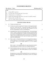
Dimensi<strong>on</strong>s <strong>of</strong> a Sleeve and Cotter Joint in terms <strong>of</strong> diameter <strong>of</strong> the rods (d)<br />
Questi<strong>on</strong>:<br />
112<br />
1.2d<br />
CLEARANCE X,Y AND Z=3mm<br />
TAPER 1:30<br />
2.4d<br />
3.3d<br />
Z<br />
Y<br />
X<br />
.3d<br />
TAPER ON<br />
THIS SIDE<br />
Fig 4.4<br />
ROD JOINTS<br />
Figure given below (fig : 4.5) shows the parts <strong>of</strong> a Sleeve and Cotter Joint.<br />
Assemble the parts correctly and then draw the following views to a scale 1 : 1<br />
(a) Fr<strong>on</strong>t view, upper half in secti<strong>on</strong>.<br />
(b) Side view, viewing from the left.<br />
3.3d 3mm<br />
1.3d<br />
d d<br />
Ø2.4d<br />
Print title and scale used. Draw the projecti<strong>on</strong> symbol. Give '8' important dimensi<strong>on</strong>s.<br />
Ø 25<br />
35<br />
110 110<br />
4<br />
42 SHAFT-A SHAFT-B 42<br />
100<br />
100<br />
SLEEVE WITH COTTER SLOTS<br />
35<br />
FRONT VIEW<br />
Ø3.5d<br />
SLEEVE AND COTTER JOINT<br />
Ø35<br />
SLEEVE AND COTTER JOINTS<br />
Fig 4.5<br />
8<br />
Ød<br />
H<br />
LEFT SIDE VIEW<br />
8<br />
Ø70<br />
Ø25<br />
Ø1.2d<br />
32<br />
110<br />
Ø35<br />
37<br />
COTTER (2-OFF)<br />
5<br />
8<br />
NOTE : FIG. NOT TO SCALE.<br />
USE DIMENSIONS GIVEN<br />
FOR DRAWING SOLUTIONS.<br />
ENGINEERING GRAPHICS<br />
H