- Page 1 and 2:
Imperial College of Science, Techno
- Page 3 and 4:
Acknowledgements Firstly, I’d lik
- Page 5 and 6:
TABLE OF CONTENTS iv 2.5 Isabelle:
- Page 7 and 8:
TABLE OF CONTENTS vi 5.3.1 Speciali
- Page 9 and 10:
TABLE OF CONTENTS viii C.1.1 fst .
- Page 11 and 12:
Chapter 1 Introduction This thesis
- Page 13 and 14:
CHAPTER 1. INTRODUCTION 3 B A C Fig
- Page 15 and 16:
CHAPTER 1. INTRODUCTION 5 pler, all
- Page 17 and 18:
CHAPTER 2. BACKGROUND AND RELATED W
- Page 19 and 20:
CHAPTER 2. BACKGROUND AND RELATED W
- Page 21 and 22:
CHAPTER 2. BACKGROUND AND RELATED W
- Page 23 and 24:
CHAPTER 2. BACKGROUND AND RELATED W
- Page 25 and 26:
CHAPTER 2. BACKGROUND AND RELATED W
- Page 27 and 28:
CHAPTER 2. BACKGROUND AND RELATED W
- Page 29 and 30: CHAPTER 2. BACKGROUND AND RELATED W
- Page 31 and 32: CHAPTER 2. BACKGROUND AND RELATED W
- Page 33 and 34: CHAPTER 2. BACKGROUND AND RELATED W
- Page 35 and 36: CHAPTER 2. BACKGROUND AND RELATED W
- Page 37 and 38: CHAPTER 2. BACKGROUND AND RELATED W
- Page 39 and 40: CHAPTER 2. BACKGROUND AND RELATED W
- Page 41 and 42: CHAPTER 2. BACKGROUND AND RELATED W
- Page 43 and 44: CHAPTER 2. BACKGROUND AND RELATED W
- Page 45 and 46: CHAPTER 3. GENERATING PARAMETERISED
- Page 47 and 48: CHAPTER 3. GENERATING PARAMETERISED
- Page 49 and 50: CHAPTER 3. GENERATING PARAMETERISED
- Page 51 and 52: CHAPTER 3. GENERATING PARAMETERISED
- Page 53 and 54: CHAPTER 3. GENERATING PARAMETERISED
- Page 55 and 56: CHAPTER 3. GENERATING PARAMETERISED
- Page 57 and 58: CHAPTER 3. GENERATING PARAMETERISED
- Page 59 and 60: CHAPTER 3. GENERATING PARAMETERISED
- Page 61 and 62: CHAPTER 3. GENERATING PARAMETERISED
- Page 63 and 64: CHAPTER 3. GENERATING PARAMETERISED
- Page 65 and 66: CHAPTER 3. GENERATING PARAMETERISED
- Page 67 and 68: CHAPTER 3. GENERATING PARAMETERISED
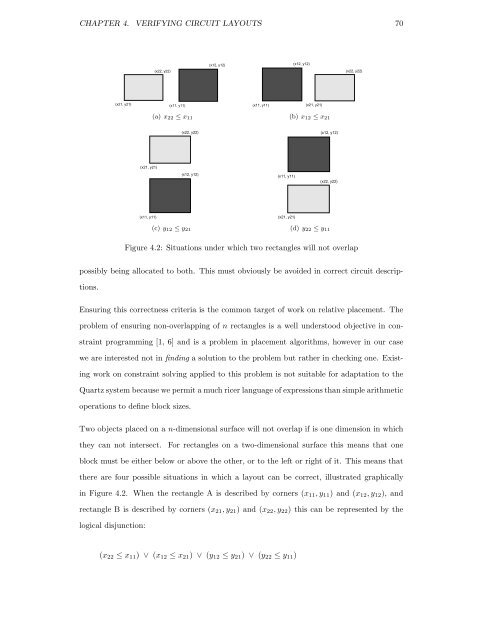
- Page 69 and 70: CHAPTER 3. GENERATING PARAMETERISED
- Page 71 and 72: CHAPTER 3. GENERATING PARAMETERISED
- Page 73 and 74: CHAPTER 3. GENERATING PARAMETERISED
- Page 75 and 76: Chapter 4 Verifying Circuit Layouts
- Page 77 and 78: CHAPTER 4. VERIFYING CIRCUIT LAYOUT
- Page 79: CHAPTER 4. VERIFYING CIRCUIT LAYOUT
- Page 83 and 84: CHAPTER 4. VERIFYING CIRCUIT LAYOUT
- Page 85 and 86: CHAPTER 4. VERIFYING CIRCUIT LAYOUT
- Page 87 and 88: CHAPTER 4. VERIFYING CIRCUIT LAYOUT
- Page 89 and 90: CHAPTER 4. VERIFYING CIRCUIT LAYOUT
- Page 91 and 92: CHAPTER 4. VERIFYING CIRCUIT LAYOUT
- Page 93 and 94: CHAPTER 4. VERIFYING CIRCUIT LAYOUT
- Page 95 and 96: CHAPTER 4. VERIFYING CIRCUIT LAYOUT
- Page 97 and 98: CHAPTER 4. VERIFYING CIRCUIT LAYOUT
- Page 99 and 100: CHAPTER 4. VERIFYING CIRCUIT LAYOUT
- Page 101 and 102: CHAPTER 4. VERIFYING CIRCUIT LAYOUT
- Page 103 and 104: CHAPTER 4. VERIFYING CIRCUIT LAYOUT
- Page 105 and 106: CHAPTER 4. VERIFYING CIRCUIT LAYOUT
- Page 107 and 108: CHAPTER 4. VERIFYING CIRCUIT LAYOUT
- Page 109 and 110: CHAPTER 4. VERIFYING CIRCUIT LAYOUT
- Page 111 and 112: CHAPTER 4. VERIFYING CIRCUIT LAYOUT
- Page 113 and 114: CHAPTER 4. VERIFYING CIRCUIT LAYOUT
- Page 115 and 116: CHAPTER 4. VERIFYING CIRCUIT LAYOUT
- Page 117 and 118: Chapter 5 Specialisation In this ch
- Page 119 and 120: CHAPTER 5. SPECIALISATION 109 opera
- Page 121 and 122: CHAPTER 5. SPECIALISATION 111 // Ha
- Page 123 and 124: CHAPTER 5. SPECIALISATION 113 circu
- Page 125 and 126: CHAPTER 5. SPECIALISATION 115 const
- Page 127 and 128: CHAPTER 5. SPECIALISATION 117 block
- Page 129 and 130: CHAPTER 5. SPECIALISATION 119 Modif
- Page 131 and 132:
CHAPTER 5. SPECIALISATION 121 Buffe
- Page 133 and 134:
CHAPTER 5. SPECIALISATION 123 a fas
- Page 135 and 136:
CHAPTER 5. SPECIALISATION 125 block
- Page 137 and 138:
CHAPTER 5. SPECIALISATION 127 y y y
- Page 139 and 140:
CHAPTER 5. SPECIALISATION 129 with
- Page 141 and 142:
CHAPTER 6. LAYOUT CASE STUDIES 131
- Page 143 and 144:
CHAPTER 6. LAYOUT CASE STUDIES 133
- Page 145 and 146:
CHAPTER 6. LAYOUT CASE STUDIES 135
- Page 147 and 148:
CHAPTER 6. LAYOUT CASE STUDIES 137
- Page 149 and 150:
CHAPTER 6. LAYOUT CASE STUDIES 139
- Page 151 and 152:
CHAPTER 6. LAYOUT CASE STUDIES 141
- Page 153 and 154:
CHAPTER 6. LAYOUT CASE STUDIES 143
- Page 155 and 156:
CHAPTER 6. LAYOUT CASE STUDIES 145
- Page 157 and 158:
CHAPTER 6. LAYOUT CASE STUDIES 147
- Page 159 and 160:
CHAPTER 6. LAYOUT CASE STUDIES 149
- Page 161 and 162:
CHAPTER 6. LAYOUT CASE STUDIES 151
- Page 163 and 164:
CHAPTER 6. LAYOUT CASE STUDIES 153
- Page 165 and 166:
CHAPTER 6. LAYOUT CASE STUDIES 155
- Page 167 and 168:
CHAPTER 6. LAYOUT CASE STUDIES 157
- Page 169 and 170:
CHAPTER 6. LAYOUT CASE STUDIES 159
- Page 171 and 172:
CHAPTER 6. LAYOUT CASE STUDIES 161
- Page 173 and 174:
CHAPTER 6. LAYOUT CASE STUDIES 163
- Page 175 and 176:
CHAPTER 7. CONCLUSION AND FUTURE WO
- Page 177 and 178:
CHAPTER 7. CONCLUSION AND FUTURE WO
- Page 179 and 180:
CHAPTER 7. CONCLUSION AND FUTURE WO
- Page 181 and 182:
CHAPTER 7. CONCLUSION AND FUTURE WO
- Page 183 and 184:
CHAPTER 7. CONCLUSION AND FUTURE WO
- Page 185 and 186:
Bibliography [1] A. Aggoun and N. B
- Page 187 and 188:
BIBLIOGRAPHY 177 [19] H. Gelernter.
- Page 189 and 190:
BIBLIOGRAPHY 179 [41] Y. Li and M.
- Page 191 and 192:
BIBLIOGRAPHY 181 [60] L. C. Paulson
- Page 193 and 194:
BIBLIOGRAPHY 183 [83] J. Voeten. On
- Page 195 and 196:
APPENDIX A. QUARTZ LANGUAGE GRAMMAR
- Page 197 and 198:
Appendix B Theoretical Basis for La
- Page 199 and 200:
APPENDIX B. THEORETICAL BASIS FOR L
- Page 201 and 202:
APPENDIX B. THEORETICAL BASIS FOR L
- Page 203 and 204:
APPENDIX B. THEORETICAL BASIS FOR L
- Page 205 and 206:
APPENDIX B. THEORETICAL BASIS FOR L
- Page 207 and 208:
APPENDIX B. THEORETICAL BASIS FOR L
- Page 209 and 210:
APPENDIX B. THEORETICAL BASIS FOR L
- Page 211 and 212:
APPENDIX B. THEORETICAL BASIS FOR L
- Page 213 and 214:
APPENDIX B. THEORETICAL BASIS FOR L
- Page 215 and 216:
APPENDIX B. THEORETICAL BASIS FOR L
- Page 217 and 218:
Appendix C Placed Combinator Librar
- Page 219 and 220:
APPENDIX C. PLACED COMBINATOR LIBRA
- Page 221 and 222:
APPENDIX C. PLACED COMBINATOR LIBRA
- Page 223 and 224:
APPENDIX C. PLACED COMBINATOR LIBRA
- Page 225 and 226:
APPENDIX C. PLACED COMBINATOR LIBRA
- Page 227 and 228:
APPENDIX C. PLACED COMBINATOR LIBRA
- Page 229 and 230:
APPENDIX C. PLACED COMBINATOR LIBRA
- Page 231 and 232:
APPENDIX C. PLACED COMBINATOR LIBRA
- Page 233 and 234:
APPENDIX C. PLACED COMBINATOR LIBRA
- Page 235 and 236:
APPENDIX C. PLACED COMBINATOR LIBRA
- Page 237 and 238:
APPENDIX C. PLACED COMBINATOR LIBRA
- Page 239 and 240:
APPENDIX C. PLACED COMBINATOR LIBRA
- Page 241 and 242:
APPENDIX C. PLACED COMBINATOR LIBRA
- Page 243 and 244:
APPENDIX C. PLACED COMBINATOR LIBRA
- Page 245 and 246:
APPENDIX C. PLACED COMBINATOR LIBRA
- Page 247 and 248:
APPENDIX C. PLACED COMBINATOR LIBRA
- Page 249 and 250:
APPENDIX C. PLACED COMBINATOR LIBRA
- Page 251 and 252:
APPENDIX C. PLACED COMBINATOR LIBRA
- Page 253 and 254:
APPENDIX C. PLACED COMBINATOR LIBRA
- Page 255 and 256:
APPENDIX C. PLACED COMBINATOR LIBRA
- Page 257 and 258:
APPENDIX C. PLACED COMBINATOR LIBRA
- Page 259 and 260:
APPENDIX C. PLACED COMBINATOR LIBRA
- Page 261 and 262:
APPENDIX C. PLACED COMBINATOR LIBRA
- Page 263 and 264:
APPENDIX C. PLACED COMBINATOR LIBRA
- Page 265 and 266:
APPENDIX C. PLACED COMBINATOR LIBRA
- Page 267 and 268:
APPENDIX C. PLACED COMBINATOR LIBRA
- Page 269 and 270:
APPENDIX C. PLACED COMBINATOR LIBRA
- Page 271 and 272:
APPENDIX C. PLACED COMBINATOR LIBRA
- Page 273 and 274:
APPENDIX C. PLACED COMBINATOR LIBRA
- Page 275 and 276:
APPENDIX C. PLACED COMBINATOR LIBRA
- Page 277 and 278:
APPENDIX C. PLACED COMBINATOR LIBRA
- Page 279 and 280:
APPENDIX D. CIRCUIT LAYOUT CASE STU
- Page 281 and 282:
APPENDIX D. CIRCUIT LAYOUT CASE STU
- Page 283 and 284:
APPENDIX D. CIRCUIT LAYOUT CASE STU
- Page 285 and 286:
APPENDIX D. CIRCUIT LAYOUT CASE STU
- Page 287 and 288:
APPENDIX D. CIRCUIT LAYOUT CASE STU
- Page 289 and 290:
APPENDIX D. CIRCUIT LAYOUT CASE STU
- Page 291 and 292:
APPENDIX D. CIRCUIT LAYOUT CASE STU
- Page 293 and 294:
APPENDIX D. CIRCUIT LAYOUT CASE STU
- Page 295 and 296:
APPENDIX D. CIRCUIT LAYOUT CASE STU
- Page 297 and 298:
APPENDIX D. CIRCUIT LAYOUT CASE STU
- Page 299 and 300:
APPENDIX D. CIRCUIT LAYOUT CASE STU
- Page 301 and 302:
APPENDIX D. CIRCUIT LAYOUT CASE STU
- Page 303 and 304:
APPENDIX D. CIRCUIT LAYOUT CASE STU
- Page 305 and 306:
APPENDIX D. CIRCUIT LAYOUT CASE STU
- Page 307 and 308:
APPENDIX D. CIRCUIT LAYOUT CASE STU
- Page 309 and 310:
APPENDIX D. CIRCUIT LAYOUT CASE STU
- Page 311 and 312:
APPENDIX D. CIRCUIT LAYOUT CASE STU
- Page 313 and 314:
APPENDIX D. CIRCUIT LAYOUT CASE STU
- Page 315 and 316:
APPENDIX D. CIRCUIT LAYOUT CASE STU
- Page 317 and 318:
APPENDIX D. CIRCUIT LAYOUT CASE STU
- Page 319 and 320:
APPENDIX D. CIRCUIT LAYOUT CASE STU
- Page 321 and 322:
APPENDIX D. CIRCUIT LAYOUT CASE STU
- Page 323 and 324:
APPENDIX D. CIRCUIT LAYOUT CASE STU
- Page 325 and 326:
APPENDIX D. CIRCUIT LAYOUT CASE STU
- Page 327:
APPENDIX D. CIRCUIT LAYOUT CASE STU