Verification of Parameterised FPGA Circuit Descriptions with Layout ...
Verification of Parameterised FPGA Circuit Descriptions with Layout ... Verification of Parameterised FPGA Circuit Descriptions with Layout ...
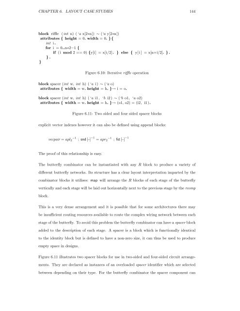
CHAPTER 6. LAYOUT CASE STUDIES 144 block riffle (int n) (‘a x[2∗n]) ∼ (‘a y[2∗n]) attributes { height = 0. width = 0. }{ int i. for i = 0..n∗2−1 { if (i mod 2 == 0) {y[i] = x[i/2]. } else { y[i ] = x[n+i/2]. } . } . } Figure 6.10: Iterative riffle operation block spacer (int w, int h) (‘a i) ∼ (‘a o) attributes { width = w. height = h. }→ i = o. block spacer (int w, int h) (‘a i1, ‘b i2) ∼ (‘b o1, ‘a o2) attributes { width = w. height = h. }→ (o1, o2) = (i2, i1). Figure 6.11: Two sided and four sided spacer blocks explicit vector indexes however it can also be defined using append blocks: vecpair = apl2 −1 ; snd [−] −1 = apr2 −1 ; fst [−] −1 The proof of this relationship is easy. The butterfly combinator can be instantiated with any R block to produce a variety of different butterfly networks. Its structure has a clear layout interpretation imparted by the combinator blocks it utilises: map will arrange the R blocks of each stage of the butterfly vertically and each stage will be laid out horizontally next to the previous stage by the rcomp block. This is a very dense arrangement and it is possible that for some architectures there may be insufficient routing resources available to route the complex wiring network between each stage of the butterfly. To avoid this problem the butterfly combinator can have a spacer block added to the description of each stage. A spacer is a block which is functionally identical to the identity block but is defined to have a non-zero size, it can thus be used to produce empty space in designs. Figure 6.11 illustrates two spacer blocks for use in two-sided and four-sided circuit arrange- ments. They are declared as instances of an overloaded spacer identifier which are selected between depending on their type. For the butterfly combinator the spacer component can
CHAPTER 6. LAYOUT CASE STUDIES 145 gr_lut gr_lut gr_lut gr_lut gr_lut gr_lut eq_lut eq_lut eq_lut eq_lut eq_lut eq_lut mux mux mux mux mux mux mux mux mux mux mux mux Figure 6.12: 6-bit 2-sorter circuit be placed anywhere within the rcomp parameter composition since the type is polymorphic, however the logical place to put the spacer in order to put room between each butterfly stage is next to the map instantiation - it can then be given the desired width and any height (less than the expected height of the map instantiation) and the series composition layout will ensure that this space is left free. 6.4.2 Implementing a bitonic merger The butterfly circuit we evaluate is a network of 2-sorters. This is a bitonic merger circuit which merges together two sorted lists. The merger is bitonic because the order of the input lists must be opposed – i.e. if one is ascending then the other must be descending or vice versa. We design a 2-sorter circuit which operates on n-bit data values and lay it out as a 4 × n block as shown in Figure 6.12. The first two columns are a comparator which outputs a control signal to the multiplexers to select the maximum and minimum values. The butterfly sorting network can be pipelined by inserting registers between each stage, replacing the R block by R ; D We can state the correctness of a pipelining arrangement with the following theorem: Theorem 24 R ; D = D ; R ⇒ butterfly n R = butterfly n (R ; D) ; D −n Proof This requires a lemma about repeated series composition:
- Page 103 and 104: CHAPTER 4. VERIFYING CIRCUIT LAYOUT
- Page 105 and 106: CHAPTER 4. VERIFYING CIRCUIT LAYOUT
- Page 107 and 108: CHAPTER 4. VERIFYING CIRCUIT LAYOUT
- Page 109 and 110: CHAPTER 4. VERIFYING CIRCUIT LAYOUT
- Page 111 and 112: CHAPTER 4. VERIFYING CIRCUIT LAYOUT
- Page 113 and 114: CHAPTER 4. VERIFYING CIRCUIT LAYOUT
- Page 115 and 116: CHAPTER 4. VERIFYING CIRCUIT LAYOUT
- Page 117 and 118: Chapter 5 Specialisation In this ch
- Page 119 and 120: CHAPTER 5. SPECIALISATION 109 opera
- Page 121 and 122: CHAPTER 5. SPECIALISATION 111 // Ha
- Page 123 and 124: CHAPTER 5. SPECIALISATION 113 circu
- Page 125 and 126: CHAPTER 5. SPECIALISATION 115 const
- Page 127 and 128: CHAPTER 5. SPECIALISATION 117 block
- Page 129 and 130: CHAPTER 5. SPECIALISATION 119 Modif
- Page 131 and 132: CHAPTER 5. SPECIALISATION 121 Buffe
- Page 133 and 134: CHAPTER 5. SPECIALISATION 123 a fas
- Page 135 and 136: CHAPTER 5. SPECIALISATION 125 block
- Page 137 and 138: CHAPTER 5. SPECIALISATION 127 y y y
- Page 139 and 140: CHAPTER 5. SPECIALISATION 129 with
- Page 141 and 142: CHAPTER 6. LAYOUT CASE STUDIES 131
- Page 143 and 144: CHAPTER 6. LAYOUT CASE STUDIES 133
- Page 145 and 146: CHAPTER 6. LAYOUT CASE STUDIES 135
- Page 147 and 148: CHAPTER 6. LAYOUT CASE STUDIES 137
- Page 149 and 150: CHAPTER 6. LAYOUT CASE STUDIES 139
- Page 151 and 152: CHAPTER 6. LAYOUT CASE STUDIES 141
- Page 153: CHAPTER 6. LAYOUT CASE STUDIES 143
- Page 157 and 158: CHAPTER 6. LAYOUT CASE STUDIES 147
- Page 159 and 160: CHAPTER 6. LAYOUT CASE STUDIES 149
- Page 161 and 162: CHAPTER 6. LAYOUT CASE STUDIES 151
- Page 163 and 164: CHAPTER 6. LAYOUT CASE STUDIES 153
- Page 165 and 166: CHAPTER 6. LAYOUT CASE STUDIES 155
- Page 167 and 168: CHAPTER 6. LAYOUT CASE STUDIES 157
- Page 169 and 170: CHAPTER 6. LAYOUT CASE STUDIES 159
- Page 171 and 172: CHAPTER 6. LAYOUT CASE STUDIES 161
- Page 173 and 174: CHAPTER 6. LAYOUT CASE STUDIES 163
- Page 175 and 176: CHAPTER 7. CONCLUSION AND FUTURE WO
- Page 177 and 178: CHAPTER 7. CONCLUSION AND FUTURE WO
- Page 179 and 180: CHAPTER 7. CONCLUSION AND FUTURE WO
- Page 181 and 182: CHAPTER 7. CONCLUSION AND FUTURE WO
- Page 183 and 184: CHAPTER 7. CONCLUSION AND FUTURE WO
- Page 185 and 186: Bibliography [1] A. Aggoun and N. B
- Page 187 and 188: BIBLIOGRAPHY 177 [19] H. Gelernter.
- Page 189 and 190: BIBLIOGRAPHY 179 [41] Y. Li and M.
- Page 191 and 192: BIBLIOGRAPHY 181 [60] L. C. Paulson
- Page 193 and 194: BIBLIOGRAPHY 183 [83] J. Voeten. On
- Page 195 and 196: APPENDIX A. QUARTZ LANGUAGE GRAMMAR
- Page 197 and 198: Appendix B Theoretical Basis for La
- Page 199 and 200: APPENDIX B. THEORETICAL BASIS FOR L
- Page 201 and 202: APPENDIX B. THEORETICAL BASIS FOR L
- Page 203 and 204: APPENDIX B. THEORETICAL BASIS FOR L
CHAPTER 6. LAYOUT CASE STUDIES 144<br />
block riffle (int n) (‘a x[2∗n]) ∼ (‘a y[2∗n])<br />
attributes { height = 0. width = 0. }{<br />
int i.<br />
for i = 0..n∗2−1 {<br />
if (i mod 2 == 0) {y[i] = x[i/2]. } else { y[i ] = x[n+i/2]. } .<br />
} .<br />
}<br />
Figure 6.10: Iterative riffle operation<br />
block spacer (int w, int h) (‘a i) ∼ (‘a o)<br />
attributes { width = w. height = h. }→ i = o.<br />
block spacer (int w, int h) (‘a i1, ‘b i2) ∼ (‘b o1, ‘a o2)<br />
attributes { width = w. height = h. }→ (o1, o2) = (i2, i1).<br />
Figure 6.11: Two sided and four sided spacer blocks<br />
explicit vector indexes however it can also be defined using append blocks:<br />
vecpair = apl2 −1 ; snd [−] −1 = apr2 −1 ; fst [−] −1<br />
The pro<strong>of</strong> <strong>of</strong> this relationship is easy.<br />
The butterfly combinator can be instantiated <strong>with</strong> any R block to produce a variety <strong>of</strong><br />
different butterfly networks. Its structure has a clear layout interpretation imparted by the<br />
combinator blocks it utilises: map will arrange the R blocks <strong>of</strong> each stage <strong>of</strong> the butterfly<br />
vertically and each stage will be laid out horizontally next to the previous stage by the rcomp<br />
block.<br />
This is a very dense arrangement and it is possible that for some architectures there may<br />
be insufficient routing resources available to route the complex wiring network between each<br />
stage <strong>of</strong> the butterfly. To avoid this problem the butterfly combinator can have a spacer block<br />
added to the description <strong>of</strong> each stage. A spacer is a block which is functionally identical<br />
to the identity block but is defined to have a non-zero size, it can thus be used to produce<br />
empty space in designs.<br />
Figure 6.11 illustrates two spacer blocks for use in two-sided and four-sided circuit arrange-<br />
ments. They are declared as instances <strong>of</strong> an overloaded spacer identifier which are selected<br />
between depending on their type. For the butterfly combinator the spacer component can


