secondary cells with lithium anodes and immobilized fused_salt
secondary cells with lithium anodes and immobilized fused_salt
secondary cells with lithium anodes and immobilized fused_salt

You also want an ePaper? Increase the reach of your titles
YUMPU automatically turns print PDFs into web optimized ePapers that Google loves.
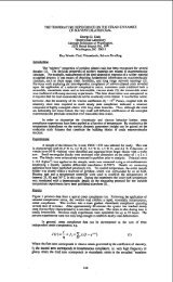
93.<br />
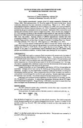
involved for constructing the phase diagram.<br />
39OK at an F2 mole fraction of 0. 65 resulted.<br />
A minimum freezing temperature of<br />
Solid fluorine is reported to undergo a transition at 45. 55OK <strong>with</strong> a heat of<br />
transition of 173. 9 cal/mole (Reference 5). Inasmuch as the solid fluorine can exist<br />
in two forms above the predicted eutectic temperature, the equilibrium diagram becomes<br />
more complicated. The theoretical phase diagram was recalculated using a<br />
value of 122 cal/mole as the heat of fusion of fluorine until the transition temperature<br />
was reached, after which the liquidus curve was assumed to undergo a change in<br />
slope corresponding to the heat of fusion plus the heat of transition.<br />
This curve was<br />
continued to meet the OFZ- rich liquidus curve leading to a theoretical minimum<br />
freezing point of 40°K at 0. 54 mole fraction F2.<br />
xAPPARATIJS<br />
A Pyrex apparatus was designed <strong>and</strong> built for this experiment. It is illustrated<br />
in Figures 1 <strong>and</strong> 2. , It consists of a central volume for the test chamber, fitted <strong>with</strong><br />
inlet tubing, a solenoid operated stirrer, <strong>and</strong> a thermowell. The central tube is sur-<br />
rounded. by several annuli arranged concentrically in the following order -- an annulus<br />
in.which the pressure can be controlled to control heat transfer rates, an annulus for<br />
liquid helium to cool'the fluids in'test, an evacuated annulus, an annulus for liquid<br />
nitrogen (heat shield) <strong>and</strong> another evacuated annulus. The evacuated annuli were<br />
silvered e'xcept for strips for observation of the interior.<br />
Liquid helium is supplied to the cooling bath from 25 liter transport Dewars<br />
connected to the apparatus b.y insulated lines. .Liquid nitrogen was poured into the<br />
heat shield when needed.<br />
Temperatures were measured <strong>with</strong> a copper-constantan thermocouple inserted<br />
in the thermowell <strong>with</strong> an external reference junction at.liquid nitrogen temperature.<br />
Thermoelectric potentials were measured <strong>with</strong> a Grey type E-3067 potentiometer<br />
<strong>and</strong> temperatures estimated from the tables <strong>and</strong> data of Powell, Bunch, <strong>and</strong> Corruccini<br />
(Reference 6). The thermocouple calibration was checked against boiling liquid<br />
nitrogen <strong>and</strong> hydrogen as fixed points. At 50°K the thermoelectric emf for copperconstantan<br />
is about 12. 1 microvolts per degree. With a sensitivity of 5 microvolts<br />
or better for the potentiometer, the sensitivity of temperature reading is about 0. 4O.<br />
MATERIA4<br />
The oxidizers tested were obtained in the gaseous state from commercial<br />
suppliers. Fluorine supplied by Air Products <strong>and</strong> Chemicals was passed over an<br />
NaF absorption scrubber to reduce the HF content to 0.02 vol 70. Oxygen difluoride<br />
supplied by Allied Chemical Division of General Chemical was also treated <strong>with</strong> NaF<br />
to remove HF.<br />
PROCEDURE<br />
The quantities of fluorine <strong>and</strong> oxygen difluoride were measured by volume in<br />
the liquid state; -weights were calculated from reported (References 7 <strong>and</strong> 8) densities.<br />
A glass ampul of calibrated volume was attached to the oxidizer supply manifold.<br />
The system was evacuated, the measuring apparatus <strong>and</strong> the ampul were<br />
chilled <strong>with</strong> LNZ to 77OK, .the test apparatus was valved off, <strong>and</strong> the oxidizer supply<br />
was valved open. When suffjcient oxidizer had condensed in the ampul, the supply<br />
was shut off, the line to the test unit was valved open, <strong>and</strong> the LN2 was removed<br />
from around the ampul, causing the oxidizer to distill into the test apparatus. When<br />
distillation was complete, the ampul was valved off.<br />
,