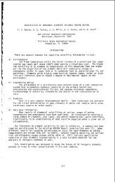
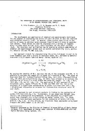
Irredie tion Time, mi&) 106. Table 3. PREPARATION OF 0,+BF4-a) Ratio F2:02 Irradiatedc) 02bF4- Produced, mg 15 1: 1 27 1.6 8.9 30 1: 1 53 3 8.8 60 1:l 96 6 7.9 60 2:l 129 12 11.0 60 3: 1 1% 16 10.6 60 5:1 127 2h 10.5 60 7:l 113 27 8.9 60 1:6 444 1.5 4.1 60e) 1: 1 45 2.7 14.9 120 3: 1 216 26 8.6 180 1:l 231 14 6.3 180 5: 1 248 47 6.9 12of 3: 1 21 2.6 0.2 a) 14 moles )f BF3 wes adde after irrai ition. b) Dose rate of 100 negarads/hour. c) d) Millimoles of oxygen used <strong>with</strong> F2:02 ratios was: 1:l = 14 moles; 2:l = 8.75 moles; 3:l = 7.0 moles; 5:1 = 4.4 moles; 7:1 = 3.5 moles; 1:6 = 21.9 moles. A second compound was formed vhich decomposed at 133% yielding about 3 moles of noncondensable gases. e) Dose rate of 25 megarads/hour. f) 10.5 moles of BF3 added to the reaction tube before irradiation. g) Molecules of product formed per 100 ev absorbed energy. ,
, 107. REFERENCES 1. 0. Ruff <strong>and</strong> M. Menzel, 2. Anorg. Chem. 211, 204 (1933). 2. A. D, Kirshenbaum <strong>and</strong> A. V. Grosse, J. Am. Chem. SOC. 8l, 1277 (1959). 3. A. V. Grosse, A. C. Streng, <strong>and</strong> A. D. Kirshenbaum, ibid. 5, 1004 (1961). 4. 5. 6. 7. 8. 9. 10. 11. 12. 13 - 14. A. G. Streng <strong>and</strong> A. V. Grosse, ibid. 88, 169 (1966). I. J. Solomon, Adv. Oxid. Research, U.S. Dept. Comm., AD 640405, (19661, Ill. Inst. of Tech. or Chem. Abst. 66, 820a6f, (1967). A. D. Kirshenbaum, A. V. Grosse, <strong>and</strong> J. G. Aston, ibid. &, 6398 (1959). A. D. Kirshenbaum <strong>and</strong> A. G. Streng, J. Chem. Phys. 2, 1440 (1961). A. C. Streng, Chem. Revs. 3, 607 (1963). T. J. Idalone <strong>and</strong> H. A. Mc Gee, Jr., J. Phys. Chem. 9, 4338 (1965). T. J. Malone <strong>and</strong> H. A. Mc Gee, Jr., ibid. 71, 3060 (1967). A. G. Streng <strong>and</strong> A. V. Grosse, Adv. in &em. Series, No. 36, Am. Chem. SOC., iu'ashington, D.C., 1962, pp. 159-164. M. S. Cohen, J. Inorg. Chem. 1, 972 (1962). A. G. Streng, J. Am. Chem. SOC. a, 1380 (1963). A. R. Young, 11, T. Hirata, <strong>and</strong> S. I. Marrow, ibid. 86, 20 (1964). 15. I. J. Solorran, R. I. Brabets, R. K. Uenishi, J. N. Kei+A, <strong>and</strong> J. M. Mc Donough, J. Inorg. Chem. 2, 457 (1964). 16. 17. 18. S. I. Xarrov <strong>and</strong> A. R. Young, 11, ibid. k, 759 (1965). C. D. agner <strong>and</strong> V. A. Campanile, Nucleonics 17, (7), 99 (1959). Quad 200 Quadrupole Mass Spectrometer, Electronic Associates Inc., Palo Alto, California. 19. I. J. Solonian, Illinois Institute of Technology, Research Institute, private communication, October 1967, in press. 20. 21. 22. N. N. Greenv~oOd, J. Chem. SOC., 3811 (1959). N. Barlett <strong>and</strong> D. Lohman, J. Chem. SOC., 5253 (1962). A. D. Kirshenbaum <strong>and</strong> A. V. Grosse, unpublished work under Air Force Contract No. AF04(611) -9555, Temple University, December 1965. 23. I. J. Soloman, et el, unpublished vork under Air Force Contract No. AF49(63) -1175, Illinois Institute of Technology, Research Institute, December 1962. ,
- Page 1 and 2:
Introduction 1. SECONDARY CELLS WIT
- Page 3 and 4:
I time curves at constant current d
- Page 5 and 6:
I 1. 2. 3. 4. 5. 6. 7. 8. 9. 10. 11
- Page 7 and 8:
7. IV IV- Equivalent Weight, gr/ Eq
- Page 9 and 10:
1 3 9 SOYO FILLER,HQT PRESS Fig. 4.
- Page 11 and 12:
11. COAL PYROLYSIS USING LASER IRRA
- Page 13 and 14:
13. Macerals. Macerals from a singl
- Page 15 and 16:
i 1 I Photochemistry. A fundamental
- Page 17 and 18:
t P li. al ’ i ._ m LL
- Page 19 and 20:
' 19. PYROLYSIS OF COAL IN A MICROW
- Page 21 and 22:
I 21. In the third stage, the gas e
- Page 23 and 24:
.4 4 0 W 0 m .d m x .-( 0 x w M m s
- Page 25 and 26:
' 25. CONCLUSIONS The principal rea
- Page 28 and 29:
' .4 b s tract 28.
- Page 30 and 31:
30. the course of the experiment Ex
- Page 32 and 33:
d (Sulfur] dt m i trogenj dt 32. E
- Page 34 and 35:
34. Table 1, Properties of Feed Mat
- Page 36 and 37:
0 0 0 m 0 VI b N 0 c, VI N 0 v, N h
- Page 38 and 39:
- Literature Cited 38 1. Gordon, K
- Page 40 and 41:
40 z - B 30 w 6 20 yl w U 10 40. 10
- Page 42 and 43:
Z 0 In 80 CK W > 6 60- 0 I- 40- Z W
- Page 44 and 45:
44. 2.0 I 1.2 - 0 2 1.0- 0.8 i TIME
- Page 46 and 47:
- 2.81 1.NITROGEN 2. SULFUR 3. GASO
- Page 48 and 49:
48. The oil from the separator is v
- Page 50 and 51:
. 50 . Table I . Properties of Pitc
- Page 52 and 53:
52. Coke yield A - - - - 0 800 900
- Page 54 and 55:
FIGURE 8. 54. t 0.5 1 800 900 1,000
- Page 56 and 57: Introduction 56. FLUORODINITROETUNO
- Page 58 and 59: chloride extractant without other h
- Page 60 and 61: 60. identified (Reference 7) as the
- Page 62 and 63: 62. to FEFO -e quite high (80 to 85
- Page 64 and 65: 64. RECENT CHEMISTRY OF THE OXYGEN
- Page 66 and 67: polymers for the conventional fuel
- Page 68 and 69: 68. In summary, two general methods
- Page 70 and 71: 70. Table XI1 Differential Thermal
- Page 72 and 73: vapor Pressure (psia) Figure 4. Vap
- Page 74 and 75: C H -0-C-NHF, - 2 5 II 0 74. H 9304
- Page 76 and 77: 76. The infrared spectrum is descri
- Page 78 and 79: , 78. PREPARATION AND POLYMERIZATIO
- Page 80 and 81: . .- . - ..... . . I ,caving the re
- Page 82 and 83: If it ~ 3 ~ o~t 7 s Y'2t the therm1
- Page 84 and 85: Chlorine Fentafluaride T q D OC 252
- Page 86 and 87: , 86. Zeections of Cl30 and AsF5. M
- Page 88 and 89: aa . - The rrost difficult rctionel
- Page 90 and 91: 90. DENSITY, VISCOSITY AND SURFACE
- Page 92 and 93: 92. If it is assumed that the syste
- Page 94 and 95: 94. After condensation of oxidizer
- Page 96 and 97: Stirring Solenoid LHe 7. Cryostat 9
- Page 98 and 99: Introduction 98. RFACTIONS OF OxYcm
- Page 100 and 101: , Acknowledgement 100. This work wa
- Page 102 and 103: 102. volume and then by pumping to
- Page 104 and 105: 104. The x-ray powder pattern (Tabl
- Page 108 and 109: I. Introduction 108. RE7IIEw OF ADV
- Page 110 and 111: 1.40 w F O/) 103-4O 'F 110. /H 0 21
- Page 112 and 113: !P, "c -- -2118.5 -195 -172 -16.1 .
- Page 114 and 115: 114. weaker than those in NF02. The
- Page 116 and 117: Compound C102F ~ 1 , 0 ~ -146 ~ 116
- Page 118 and 119: 118. fom such salts as cS+m8- have
- Page 120 and 121: 120. DETONABILITY TESTING AT NONAMB
- Page 122 and 123: I 122. top) is closed with caps whi
- Page 124 and 125: 124. five pieces of MDF, each 20.00
- Page 126 and 127: 126. auxiliary equipment. For conve
- Page 128 and 129: 128. reliability. Details of most o
- Page 130 and 131: 130. The time required for the deto
- Page 132 and 133: 132. Fig. 2 Typical Witness Plate
- Page 134 and 135: I ll 134. L, ALUMINUM 011+ ‘7 I-
- Page 136: W (3 3 a (3 W m 3 0 v) W E k- / W 3