secondary cells with lithium anodes and immobilized fused_salt
secondary cells with lithium anodes and immobilized fused_salt
secondary cells with lithium anodes and immobilized fused_salt

Create successful ePaper yourself
Turn your PDF publications into a flip-book with our unique Google optimized e-Paper software.
Introduction<br />
1.<br />
SECONDARY CELLS WITH LITHIUM ANODES AND<br />
IMMOBILIZED FUSED-SALT ELECTROLYTES<br />
H. Shimotake, G. L. Rogers, <strong>and</strong> E. J. Cairns<br />
Argonne National Laboratory<br />
9700 South Cass Avenue<br />
Argonne, Illinois<br />
60439<br />
Today's rapidly-advancing technology requires a wide spectrum of power<br />
sources <strong>and</strong> energy-storage devices. In many applications, the power sources are<br />
required to have a minimum size or weight per unit of power or energy. These relquirements<br />
have motivated a great deal of the recent work on high-specific-energy<br />
(watt-hr/lb) <strong>and</strong> high-specific-power (watt/lb) <strong>secondary</strong> <strong>cells</strong>. The maximization<br />
of the specific energy requires that reactants of low equivalent weight <strong>and</strong> high<br />
free energy of reaction be used. For high specific energy (> 50 watt-hr/lb) <strong>cells</strong><br />
<strong>with</strong> aqueous electrolytes, zinc <strong>and</strong> cadmium have served as anode materials while<br />
nickel oxide, silver oxide, <strong>and</strong> oxygen (or air) have served as cathode materials. 1<br />
The elimination of water from the electrolyte permits more reactive metals such as<br />
calcium <strong>and</strong> the alkali metals to be considered as anode materials. Lithium has a<br />
~ 3<br />
very low equivalent weight <strong>and</strong> low electronegativity, making it particularly attractive<br />
as an anode material for high specific energy <strong>cells</strong>. A number of cathode<br />
materials have been used in combination <strong>with</strong> nonaqueous electrolytes <strong>and</strong> <strong>lithium</strong><br />
<strong>anodes</strong>, depending on the operating temperature <strong>and</strong> the electrolyte.<br />
Lithium-anode <strong>cells</strong> designed for operation at room temperature use nonaqueous<br />
electrolytes comprised of solutions of inorganic <strong>salt</strong>s such as Li PF4 or<br />
LiC104 dissolved in organic solvents such as propylene carbonate or dimet$j sulfoxide;<br />
the cathodes are usually metal halides such as NiF4, CuF2 or CuC1. Although<br />
these <strong>cells</strong> have the potentiality of supplying over 100 watt-hr/lb at low<br />
discharge rates, their specific power is low (2-20 watt/lb) ,Is3 limiting their<br />
range of applicability. The specific power for <strong>cells</strong> <strong>with</strong> organic-solvent electrolytes<br />
is low because of the low conductivity of the electrolyte (% 10-2 ohm-l cm-l).<br />
The use of <strong>fused</strong>-<strong>salt</strong>s as electrolytes provides very high conductivities<br />
(1-4 ohm-l cm-l) thus allowing specific powers in excess of 100 watt/lb to be<br />
achieved.4-8 Because of their relatively high melting points, <strong>fused</strong>-<strong>salt</strong> electrolytes<br />
require elevated operating temperatures (26O-65O0C). , A number of <strong>secondary</strong><br />
9<br />
<strong>cells</strong> <strong>with</strong> <strong>fused</strong>-<strong>salt</strong> electrolytes have been investigated, including sodium/bismuth,<br />
<strong>lithium</strong>/chlorine ,'*' <strong>lithium</strong>/tell~rium,~-~ <strong>and</strong> <strong>lithium</strong>/selenium,10 all using free<br />
liquid electrolytes.<br />
A general indication of the theoretical maximum specific energies of some<br />
couples suitable for use <strong>with</strong> <strong>fused</strong>-<strong>salt</strong> electrolytes is given in Figure 1, where<br />
the specific energy (as calculated from the equivalent weight of the cell products<br />
indicated <strong>and</strong> the average emf of the couple) is plotted against the equivalent<br />
weight of the active material. Usually, the higher specific energy materials are<br />
more difficult to h<strong>and</strong>le from a corrosion viewpoint.<br />
, . A great deal of design flexibility <strong>and</strong> compactness can be gained by immoiJ<br />
i<br />
bilizing the <strong>fused</strong>-<strong>salt</strong> electrolyte either in an absorbent matrix or in the form of<br />
a rigid paste.ll-l3 This work deals <strong>with</strong> <strong>secondary</strong> <strong>cells</strong> having liquid <strong>lithium</strong><br />
<strong>anodes</strong>, liquid bismuth or tellurium cathodes <strong>and</strong> <strong>fused</strong>-<strong>lithium</strong>-halide electrolytes<br />
<strong>immobilized</strong> as a rigid paste, operating at temperatures in the range 380 to 485°C.<br />
'<br />
Experimental<br />
Typical lithiudbismuth <strong>and</strong> <strong>lithium</strong>/tellurium <strong>cells</strong> are shown in Figures<br />
2 <strong>and</strong> 3. The cell housing in Figure 2 was made from Type 316 stainless steel;<br />
the electrode compartments were 3.2 mm deep, <strong>and</strong> had 4 concentric fins which
2<br />
served as current collectors. ,The exposed electrolyte area was 1.98 cm ,<br />
<strong>and</strong> the paste electrolyte thickness was 0.34 cm. Prior ,to assembly, the<br />
anode compartment was loaded <strong>with</strong> 0.064 gm of <strong>lithium</strong> (Foote Mineral Co.,<br />
0.003 % Na, 0.003% K, 0.003% N2, 0.003% C12, surface oxide removed), heated<br />
to 530°C to ensure good wetting of the current collector. The cathode compartment<br />
contained 2.764 gm of bismuth (United Mineral <strong>and</strong> Chemical Corp.,<br />
99.999% minimum purity). These amounts of reactants correspond to a cathodealloy<br />
composition of 41 a/o Li in Bi at complete discharge, <strong>and</strong> a cell capacity<br />
of 0.25 amp-hr. The cell was prepared <strong>and</strong> assembled under a high-purity helium<br />
atmosphere.14 No gaskets were used; the smooth-surfaced electrolyte disc provided<br />
a leak-tight seal against the cell housing.<br />
consisting of sheets of sintered porous stainless steel in the anode compart-<br />
ment, <strong>and</strong> a network of pure-iron wires in the cathode compartment in place of<br />
the meshes shown in Figure 3. The exposed electrolyte area was 3.25 cm2; the<br />
electrolyte thickness was 0.32 cm. The cell compartments were loaded <strong>with</strong> 0.75<br />
pm of <strong>lithium</strong> <strong>and</strong> 5.45 gm of tellurium, (American Smelting <strong>and</strong> Refining Co.,<br />
99.999% minimum purity) corresponding to 71.6 a/o Li in Te at complete discharge.<br />
The electrolyte was the ternary eutectic composed of 11.7 m/o LiF -<br />
29.1 m/o LiCl - 59.2 m/o LiI, which melts at 340.9'C <strong>and</strong> has a s ecific con-<br />
ductance of 2.3 ohm-l cm-l at 375'C <strong>and</strong> 3.0 ohm-l cm-l at 475"C.p5 The eutectic<br />
was prepared from weighed amounts of the pure <strong>salt</strong>s: LiF, LiC1, <strong>and</strong> LiI all<br />
supplied by Anderson Physics Laboratories, Inc. After the components were melted<br />
together to form the eutectic, the electrolyte was solidified, pulverized to -300<br />
mesh, <strong>and</strong> mixed (50 w/o) <strong>with</strong> an inert filler.materia1. The electrolyte-filler<br />
powder mixture was then molded into discs. For the Li/Bi cell, discs 1.85 cm in<br />
dia. were prepared by pressing,the electrolyte-filler powder first at room tem-<br />
perature to form "cold-pressed" discs, <strong>and</strong> then at 400°C for final densification.<br />
All operations except for the hot-pressing were carried out in a pure helium at-<br />
mosphere. For the Li/Te cell, discs 2.5 cm in dia. were pressed at room tempera-<br />
ture <strong>and</strong> sintered at 4OO0C <strong>with</strong>out pressing, eliminating all exposure to air.<br />
The paste electrolyte has a continuous phase of <strong>fused</strong>-<strong>lithium</strong>-halide<br />
eutectic at the cell operating temperature. The relative amounts of finelydivided<br />
inert filler <strong>and</strong> <strong>lithium</strong> halide are chosen such that the electrolyte fills<br />
the interstitial spaces among the very small filler particles, <strong>and</strong> holds the paste<br />
firmly by means of its high surface tension, low contact angle <strong>with</strong> the filler,<br />
<strong>and</strong> the small pore size of the compact. Similar paste electrolytes have been uspd<br />
<strong>with</strong> success in molten-carbonate fuel ~ells,.ll-~~<br />
2.<br />
The lithiiim!tel I.urium c.el1.; macle of pure iron, had current collectors<br />
The measurements of cell performance were carried out <strong>with</strong> the aid of a<br />
constant-current DC power supply, precision voltmeters <strong>and</strong> ammeters (1/4 percent),<br />
<strong>and</strong> a strip-chart recorder. The voltage-current density curves for the discharge<br />
mode of operation were measured starting <strong>with</strong> the cell in the fully-charged condition;<br />
the curves for the charge mode of operation were usually measured from<br />
the fill ly-discharged cnndi tinn. A1 1 resiil ts Are reported nn II resistance-included<br />
basis.<br />
furnace.<br />
The <strong>cells</strong> were held at operating temperature in an electrically-heated tube<br />
Results <strong>and</strong> Discussion<br />
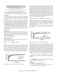
The voltage-current density curves for the Li/Bi cell operating at 380".<br />
453', <strong>and</strong> 485'C are shown in Figure 4. As might be expected, the highest performance<br />
in hnth charge <strong>and</strong> discharge modes was obtained at the highest temperature.<br />
Current densities up to 2.2 amp/cm2 were obtained, based on the effective electrode<br />
area of 1 cm2 (the electrode compartments were only about half-filled <strong>with</strong><br />
active materials during these experiments).<br />
Since,&he cathode composition during<br />
che discharge experiments averaged about 5 a/o Li,- these performances are typical<br />
of those obtainable near the beginning of the plateau of the corresponding voltage-
I<br />
time curves at constant current discharge.<br />
was 0.57 watt/cm2 at 0.6 volt.<br />
3.<br />
The slopes of the charge <strong>and</strong> discharge curves in Figure 4 are different<br />
because of the difference in state of charge for the two modes of operation. The<br />
internal resistance of the cell is expected to be lower for the discharge curves<br />
because most of the original amount of <strong>lithium</strong> was still in the anode compartment<br />
when the discharge data were taken. During the charging experiments, however,<br />
almost no <strong>lithium</strong> was present in the <strong>lithium</strong> compartment, resulting in a relatively<br />
high internal resistance. When charge <strong>and</strong> discharge curves are taken under identical<br />
conditions, the curves have the same slope. The internal resistance of the cell<br />
at high current densities was 0.45 ohm at 485"C, compared to a value of 0.23 ohm<br />
calculated from the specific conductance of the electrolyte <strong>and</strong> a paste-to-pure<br />
electrolyte resistivity ratio of 2.11,13<br />
The maximum power density at 485OC<br />
This discrepancy could be caused by the<br />
presence of some Li20 resulting from hydrolysis of the <strong>lithium</strong> halides during hot-<br />
pressing OK incomplete wetting of the paste by Li.<br />
From the reasonably high current density capabilities of the Li/Bi cell<br />
of Figure 4, it is clear that the cell can be fully charged from complete discharge<br />
in about 15 minutes.<br />
The performance characteristics of the (larger) Li/Te cell operating at<br />
475°C are shown in Figure 5. As expected on the basis of the emf measurements<br />
of Foster <strong>and</strong> Lid7 <strong>and</strong> earlier experience <strong>with</strong> Li/Te cell^,^-^ the open circuit<br />
voltage was 1.7 to 1.8 volts, <strong>and</strong> the voltage-current density curves were straight<br />
lines, indicating the absence of any significant concentration or activation overvoltages.<br />
The short-circuit current density was 2.2 amp/cm2, <strong>and</strong> the maximum power<br />
density was 1 watt/cm2 at 0.9 volt, a considerable improvement in power density<br />
over the Li/Bi cell.<br />
The internal resistance of the Li/Te cell during discharge was 0.24 ohm,<br />
compared to 0.065 ohm calculated from the electrolyte conductivity <strong>and</strong> a paste-<br />
to-pure electrolyte resistivity ratio of 2. The ratio of observed-to-calculated<br />
cell resistances is higher for the Li/Te cell than for the Li/Bi cell, possibly<br />
because of the fact that the paste electrolyte disc for the Li/Te cell was not<br />
hot-pressed, <strong>and</strong> therefore probably contained voids which increased the resistiv-<br />
ity of the paste.<br />
The Li/Te cell, <strong>with</strong> a capacity of 2.91 amp-hr could be fully charged<br />
from complete discharge in less than half an hour. This is a much higher charge<br />
rate than can be'used <strong>with</strong> <strong>secondary</strong> <strong>cells</strong> having aqueous electrolytes or <strong>cells</strong><br />
,<br />
<strong>with</strong> nonaqueous organic solvent electrolytes.<br />
Extensive investigations of constant-current charge <strong>and</strong> discharge char-<br />
acteristics, charge retention, <strong>and</strong> cycle life still remain to be done. The data<br />
presented above were interesting enough, however, that some preliminary design<br />
calculations have been performed, based upon the voltage-current density curves<br />
of Figures 4 <strong>and</strong> 5.<br />
The principles, equations, <strong>and</strong> sample calculations involved in the design<br />
of <strong>secondary</strong> batteries have already been discussed elsewhere4, therefore, no detailed<br />
explanations will be given here. The most important parameter in many<br />
applications is battery weight; therefore, the energy <strong>and</strong> power values are expressed<br />
per unit weight as specific energy (watt-hr/lb) <strong>and</strong> specific power<br />
(watt/lb). The calculation of battery weight involves the selection of the<br />
ratio of reactant weights, <strong>and</strong> the calculation of the weights of reactants,<br />
electrolyte, cell housing, terminals, etc. required, per unit of active cell<br />
area. The specific power available is calculated from the current density-voltage<br />
curve <strong>and</strong> the battery weight per unit active area. The specific energy is calculated<br />
from the average cell operating voltage, the amount of <strong>lithium</strong> per unit of<br />
active cell area <strong>and</strong> the battery weight per unit of active area.4 The values<br />
used in these calculations are summarized in Table I.
4.<br />
The results of the design calculations for Li/Bi <strong>and</strong> Li/Te <strong>secondary</strong><br />
batteries are shown in Figure 6. Because of the lower equivalent weight <strong>and</strong><br />
higher electronegativity, the Li/Te cell has higher specific energy <strong>and</strong> specific<br />
power capabilities than the Li/Bi cell. As an example, Figure 6 shows that for<br />
the 30-minute-discharge rate, a Li/Bi cell having 3 <strong>cells</strong> per inch <strong>and</strong> an elec-<br />
trolyte thickness of 0.32 cm has a specific power of 43 watt/lb <strong>and</strong> a specific<br />
energy of 21 watt-hr/lb, whereas the Li/Te cell of similar dimensions can attain<br />
110 watt/lb <strong>and</strong> 55 watt-hr/lb. The design analysis results presented in Figure<br />
6 also indicate that if the electrolyte thickness is decreased to 0.1 cm, it is<br />
possible to achieve 90 watt/lb <strong>and</strong> 45 watt-hr/lb for the Li/Bi cell <strong>and</strong> 200<br />
watt/lb <strong>and</strong> 110 watt-hr/lb for the Li/Te cell. The performances of some other<br />
types of <strong>secondary</strong> batteries including lead-acid, nickel/cadmium, sodium/sulfur,<br />
<strong>and</strong> Iithiumlchlnrine ere presented in Figure 6 for comparison.<br />
Possible applications for <strong>secondary</strong> <strong>cells</strong> <strong>with</strong> the characteristics of<br />
fhe Li/Te cell include space power sources, military communications power sources,<br />
military vehicle propulsion, <strong>and</strong> perhaps special commercial vehicle propulsion.<br />
The areas which deserve further attention in the development of Li/Bi<br />
<strong>and</strong> Li/Te <strong>cells</strong> include the optimization of paste electrolyte properties (par-<br />
ticularly the resistivity), current collection, corrosion, cycle life, <strong>and</strong> thermal<br />
cycling.<br />
Conclusions<br />
1. It is possible to form acceptable paste electrolytes from <strong>fused</strong><strong>lithium</strong><br />
halides <strong>and</strong> inert filler materials. The paste electrolytes presently<br />
show two to three times the expected electrolytic resistivities.<br />
2. Lithium/bismuth <strong>and</strong> <strong>lithium</strong>/tellurium <strong>cells</strong> operating <strong>with</strong> <strong>lithium</strong><br />
halide saste electrolytes can operate at power densities of 0.57 <strong>and</strong> 1.0<br />
watt/cm , respectively at about 48OoC.<br />
3. These <strong>cells</strong> can be charged at very high rates (less than 30 minutes),<br />
making them possible c<strong>and</strong>idates for many applications where fast recharge is important.<br />
4. Design calculations indicate that the Li/Te cell <strong>with</strong> paste electrolyte<br />
can be expected to show a specific power in excess of 360 watt/lb <strong>and</strong> a<br />
specific energy of 80 watt-hr/lb, suggesting many possible applications, including<br />
special vehicle propulsion <strong>and</strong> energy storage.<br />
Acknowledgment<br />
It is a pleasure to thank Mr. J. Gerard for help <strong>with</strong> some of the experiments,<br />
<strong>and</strong> Drs. A. D. Tevebaugh, C. E. Johnson, <strong>and</strong> M. S. Foster for helpful discussions<br />
during the course of this work. Mr. B. S. Baker of the Institute of Gas<br />
Technology generously provided advice <strong>and</strong> materials on the preparation of paste<br />
electrolytes.<br />
1<br />
i
I<br />
1.<br />
2.<br />
3.<br />
4.<br />
5.<br />
6.<br />
7.<br />
8.<br />
9.<br />
10.<br />
11.<br />
12.<br />
13.<br />
14.<br />
15.<br />
16.<br />
17.<br />
References<br />
R. Jasinski, "High-Energy Batteries", Plenum Press, New York (1967).<br />
A. ?-I. Yoos <strong>and</strong> N. I. Palmer, in Proc. 21st Ann. Power Sources Conf.,<br />
PSC Publications Committee, Red Bank, New Jersey (1967).<br />
H. K. Seiger, S. Charlip, A. E. Lyall <strong>and</strong> R. C. Shair, in Proc. 2zst<br />
dm. Podei. Sources Conf., PSC Publications Committee, Red Bank, New<br />
Jersey (1967).<br />
H. Shimotake <strong>and</strong> E. J. Cairns, Presented at the Intersociety Energy<br />
Conversion Engineering Conf., Miami Beach, August, 1967, in Advances<br />
ir?. Zdergy Conversion Engineering, her. SOC. Mech. Eng., New York<br />
(1967), p. 951.<br />
E. J. Cairns <strong>and</strong> H. Shimotake, Presented at her. Chem. SOC. Meeting,<br />
Chicago, September 1967, Abstr. No. L-70; See also Preprints of Papers<br />
?l.e:ented to t;!e Division of Fuel Chemistry 22, No. 3, 321 (1967).<br />
H. Shimotake, G. L. Rogers, <strong>and</strong> E. J. Cairns, Presented at Electrochem.<br />
SOC. Xeeting, Chicago, October, 1967, Abstr. No. 18; See also Extended<br />
/bctwi~~-s J-1 0.' the Battery Diu., 12, 42 (1967).<br />
R. A. Rightmire <strong>and</strong> A. L. Jones, in Proc. 2Zst Ann. Power Sources Conf.,<br />
PSC Publications Committee, Red Bank, New Jersey (1967).<br />
H. A. Wilcox, in Proc. 2Zst Ann. Power Sources Conf., PSC Publications<br />
Committee, Red bank, New Jersey (1967).<br />
H. Shimotake <strong>and</strong> E. J. Cairns, Presented at Electrochem. SOC. Meeting,<br />
Dallas, May, 1967, Abstr. No. 143; See also Extended Abstrs. of the<br />
Inr,v:z&Z Zlsctro1dtic Diu., 3, 4 (1967).<br />
H. Shimotake <strong>and</strong> E. J. Cairns, Submitted for Presentation at the Inter-<br />
national Power Sources Symposium, Brighton, September, 1968.<br />
G. H. .J. Broers <strong>and</strong> M. Schenbe, in "Fuel Cells", Vol. 2, G. J. Young,<br />
Ed., Reinhold, New York (1963).<br />
B. S. Baker, L. G. Marianowski, J. Zimmer <strong>and</strong> G. Price, in "Hydrocarbon<br />
Fuel Cell Technology", B. S. Baker, Ed., Academic Press, New York (1965).<br />
A. D. S. Tantram, A. C. C. Tseung, <strong>and</strong> B. S. Harris, in "Hydrocarbon Fuel<br />
Cell Technology", B. S. Baker, Ed., Academic Press, New York (1965).<br />
C. E. Johnson, Y. S. Foster, <strong>and</strong> PI. L. Kyle, UucZear Appl., 3, 563 (1967).<br />
C. E. Johnson, Submitted for Presentation at the San Francisco Meeting of<br />
The her. Chem. SOC., Apr., 1968.<br />
!I. s. Foster, S. E. Wood, <strong>and</strong> C. E. Crouthamel, Inorg. Chern., 3, 1428 (1964).<br />
>I. s. Foster <strong>and</strong> C. C. Liu, J. Phys. Chem., 70, 950 (1966).<br />
,
,<br />
Open-circuit voltage, volts<br />
6.<br />
Table I<br />
Data for Battery Design Calculations<br />
Short-circuit current density, amp/cm 2<br />
for electrolyte thickness 0.3 cm<br />
for electrolyte thickness 0.1 cm<br />
Cathode allay, fully discharged<br />
composition, a/o Li<br />
3<br />
density, g/cm<br />
3<br />
Anode metal density, g/cm,<br />
Current efficiency, %<br />
Cell partition thickness, cm/cell<br />
3<br />
Density of housing material, g/cm<br />
3<br />
Density of paste electrolyte, g/cm<br />
Weight allowance for framing, terminals,<br />
etc. 2 (electrolyte + partition weight)<br />
Li!Ri Li/Te<br />
0.8 1.7<br />
1.8 2.2<br />
6.1 7.0<br />
70 60<br />
4.4 3.3<br />
0.53 0.53<br />
100 100<br />
0.1 0.1<br />
7.8 7.8<br />
3.0 3.0<br />
50 50<br />
,
7.<br />
IV IV-<br />
Equivalent Weight, gr/ Equivalent<br />
Fig. 1. Relationship between theoretical specific<br />
energy <strong>and</strong> equivalent weight<br />
Fig. 2. View of <strong>lithium</strong>-bismuth-cell parts. Enough cell parts<br />
to make a two-cell battery are shown.<br />
IV
8.<br />
Fig. 3a. View of assembled <strong>lithium</strong>-tellurium cell<br />
Fig. 3b. View of <strong>lithium</strong>-tellurium-cell parts
1<br />
3<br />
9<br />
SOYO FILLER,HQT PRESS<br />
Fig. 4. ,Voltage-current density curves for a <strong>lithium</strong>-bismuth cell<br />
I I I I<br />
- LI/ LMLi in Te (I)<br />
ANODE AREA 325 CM' -<br />
- CATHODE AREA 325 CM' -<br />
INTERELECTRODE<br />
- DISTANCE 0 32 CM -<br />
CAPACITY 291 AH<br />
- TEMPERATURE 475-C -<br />
PASTE ELECTROLYTE<br />
- 50 '4 FILLER COLD PRESS-<br />
- -<br />
- -<br />
- -<br />
- -<br />
- -<br />
CHARGE<br />
- -<br />
- -<br />
- 2- -<br />
I I<br />
2 I 0 2 3<br />
Fig. 5. Voltage-current density curx'es for a <strong>lithium</strong>-tellurium cell<br />
-<br />
,
10.<br />
SPECIFIC ENERGY , watt-hr/lb<br />
Fig. 6. Specific power-specific energy curves<br />
for some <strong>secondary</strong> batteries<br />
,<br />
\<br />
/I
11.<br />
COAL PYROLYSIS USING LASER IRRADIATION<br />
F. S. Karn, R. A. Friedel, <strong>and</strong> A. G. Sharkey, Jr.<br />
U.S. Department of the Interior, Bureau of Mines<br />
Pittsburgh Coal Research Center, Pittsburgh, Pa. 15213<br />
INTRODUCTION<br />
The purpose of this investigation is to observe the effect of laser irradiation<br />
on the pyrolysis of coal. Coal irradiated <strong>with</strong> laser light can decompose<br />
into gases rich in acetylene. Coal pyrolysis at the usual coking temperatures<br />
, yields gases high in methane but very low in acetylene. The acetylene/methane ratio<br />
<strong>and</strong> the probable comercial value of the product gas should be related directly to<br />
the temperature of the decomposing coal.<br />
Conventional coal pyrolysis varies in temperature from 450" to 1,400"C <strong>and</strong> includes<br />
hundreds of different processes <strong>and</strong> coals. A typical high-temperature pyrolysis<br />
gas was obtained from a Pittsburgh seam (hvab) coal carbonized at 900" C.51<br />
Fifteen percent of the coal (40.7 percent volatile matter) was collected as gas<br />
(table 1). Laser irradiation can bring about significant changes in the C,H,/CH4<br />
ratio by increasing pyrolysis temperature. The equilibrium constant for the<br />
reaction<br />
increases from at 1,000" K to lo+' at 4,000" K. Temperatures resulting from<br />
laser irradiation could be very high. The energy concentration due to a 6-joule<br />
focused beam from a ruby laser is sufficient to raise the temperature of a perfect<br />
absorber by 14,000' C. This estimate is based on the laser energy <strong>and</strong> on the heat<br />
capactty of the target. However, much of the laser energy is dissipated by reflection,<br />
conduction, <strong>and</strong> vaporization. In these experiments <strong>with</strong> coal the maximum<br />
target temperature was estimated to be less than 1,300" K--largely due to coal volatility.<br />
Interesting observations of tar et temperatures of laser-irradiated solids<br />
have been reported. Berkowitz <strong>and</strong> Chupkal .? analyzed the vapor ejected from graphite<br />
<strong>and</strong> found it compatible <strong>with</strong> an assumption of thermodynamic equilibrium <strong>and</strong> a temperature<br />
of 4,000' K. Verber <strong>and</strong> Adelman,'/ using tantalum as a target, measured<br />
thermionic emission due to a surface temperature increase which was calculated<br />
from classical heat transfer theory. In the following experiments temperatures<br />
have not been measured directly due to the small size of the coal crater <strong>and</strong> to<br />
the rapid heating <strong>and</strong> cooling of the sample.<br />
EXPERPIENTAL<br />
A variety of coals <strong>and</strong> coal macerals have been exposed to laser irradiation.<br />
Using a focused beam, energy concentrations as high as 100 megawatts per square<br />
centimeter can be reached. The general procedure has been to seal the coal sample<br />
in a glass vessel through which the laser beam'can be fired. The vessel was evacuated<br />
or evacuated <strong>and</strong> partially refilled <strong>with</strong> a specific gas before irradiation.<br />
Samples, usually about 8 mm cubes, were sealed in glass tubes 10 mm i.d. <strong>and</strong> 90 mm<br />
long.k/ Samples were dried under vacuum at 100" C for 20 hours, then sealed <strong>and</strong><br />
irradiated. The usual irradiation was 1 pulse of a 6-joule ruby laser beam which<br />
was focused by a convex lens. Gaseous products were analyzed by the mass spectraneter<br />
in two or more fractions distilling from liquid nitrogen, dry ice, ice water,<br />
room temperature, <strong>and</strong> 60" C baths. Both total volume <strong>and</strong> gas distribution were<br />
determined for each fraction. Solid products were obtained from the glass walls<br />
for ultimate analysis or for inspection by infrared spectrometry.
H2<br />
co<br />
12.<br />
Table 1.- Product gas<br />
93OOC Carbonization Laser irradiation<br />
Mole percent<br />
55.6<br />
7.4<br />
0.4<br />
31.5<br />
0.05<br />
3.4<br />
1.2<br />
0.5<br />
0.0<br />
15<br />
< 0.002<br />
Weig<br />
t percent o<br />
CzHzICH4<br />
co a1<br />
52.2<br />
22.5<br />
a. 7<br />
5.1<br />
10.6<br />
0.0<br />
0.0<br />
0.0<br />
0.9<br />
52 ,<br />
In studying any new process for coal pyrolysis, there are several useful var-<br />
iables to be considered. Among these are coal rank, maceral, particle size, <strong>and</strong><br />
atmosphere. There are also several variables which are characteristic of the pro-<br />
cessing unit. For the laser they are quantity of energy discharged, rate of dis-<br />
charge, area of target, <strong>and</strong> wavelength of radiant energy.<br />
Coals have been treated <strong>with</strong> the same total light energy from 3 different<br />
lasers. Lasers used in these experiments were as follows: The ruby laser delivers<br />
6 joules of 6,943 A light in about 1 millisecond. Source of the light is a cylin-<br />
drical ruby 76 mm long by 6.3 nun in diameter. It is activated by a xenon flash<br />
lamp <strong>and</strong> a capacitor capable of delivering a 2,000-volt pulse. The neodymium laser<br />
is a glass rod 152 mm long <strong>and</strong> capable of a 28-joule pulsed discharge. The third<br />
laser type is a continuous CO2 laser. Its total power output is only 10 watts<br />
(10 joules/sec) but since it operates continuously the total energy <strong>and</strong> the quantity<br />
of product gas can be made to equal that of the pulsed lasers. Irradiation frq<br />
the C02 laser has a wavelength of 106,000 A.<br />
RESULTS<br />
A comparison of product gases from a 900” C carbonization <strong>and</strong> from irradiation<br />
by a ruby laser verified the prediction of higher C2H2 to C q ratio for the laser<br />
(table 1).<br />
-<br />
Rank. Coal composition <strong>and</strong> coal utilization vary widely <strong>with</strong> rank. Irradiaci,...<br />
....<br />
LLYLl rLodiicts as a functioii of rank iv’ere studied earlier <strong>and</strong> the restilts are sum-<br />
marized in table 2.31<br />
As rank decreases the yield of gaseous product increases.<br />
Yields of acetylene, hydrogen, <strong>and</strong> HCN reach a maximum for a high-volatile bitumin-<br />
ous coal.<br />
2.1<br />
I<br />
‘r<br />
i
13.<br />
Macerals. Macerals from a single coal setam can be separated visually or by<br />
specific gravity. They provide information about the origin of a coal <strong>and</strong> about its<br />
coking properties. Maceral separation is a tedious job <strong>and</strong> well separated samples<br />
are usually small.l/ Macerals of Hernshaw (hvab) coal in sufficient quantity for<br />
laser pyrolysis were irradiated (table 3). As hydrogen <strong>and</strong> volatile matter in the<br />
maceral increased the product gas increased, <strong>and</strong> the quality of the product gas<br />
(based on C2H21CH4 ratio) decreased.<br />
Table 2.- Product gases from laser irradiation of coals<br />
Anthracite Pocahontas Pittsburgh Lignite<br />
lvb hvab<br />
Moles x lo7<br />
13 23 30 21<br />
8 5 12 24<br />
4 1 3 10<br />
1 1 3 1<br />
3 4 9 6<br />
0.3 0.3 1.2 0.7<br />
TO t a 15' 31 35 60 63<br />
- a/ H20, N2, 02 free.<br />
Table 3.- Gas from laser irradiation of macerals<br />
of Hernshaw (hvab) coal<br />
H2 3 Volatile mat er, Product as<br />
Maceral De r cenid Dercenta 5 Moles x 10' 'C?H?/CHI.<br />
Fu s ini te 3.2 13.4 43 59<br />
Micrinite 4.8 31.4 52 34<br />
Vitr inite 5.4 33.7 90 12<br />
Exini te 6.4 55.4 103 8<br />
- a/ See reference 2.<br />
Particle Size. Variation of gas yield <strong>with</strong> particle size was studied.<br />
Samples of Pittsburgh seam coal <strong>with</strong> particle diameters from 240 p down to 10 p<br />
(figure 1) were irradiated. For the smaller particles there was a modest decrease<br />
in methane <strong>and</strong> an increase in acetylene. This may indicate less cooling by conduc-<br />
tion <strong>and</strong> higher temperatures.<br />
Types of Lasers. Although laser activity has been produced in many different<br />
materials, this study has been carried out using only three--ruby, neodymium, <strong>and</strong><br />
carbon dioxide. The ruby is a pink crystal of A1203 <strong>with</strong> 0.05 weight percent of<br />
Cr2O3. The chromium ions, excited by the xenon flash lamp, emit a pulse of 6,943 A<br />
laser light. The intensity of this pulse can be varied by changing the input to the<br />
lamp, by focusing the laser beam, <strong>and</strong> by Q-switching to shorten the discharge time.<br />
The st<strong>and</strong>ard irradiation for these experiments was a 6-joule pulse discharged in<br />
about 1 millisecond. Without optical alteration this produces a crater 6 m in<br />
diameter equal to the ruby rod) <strong>and</strong> an energy concentration at the target of<br />
14 kw cm-'. With a focusing lens this is increased to over 40 kw cm-2 <strong>and</strong>, using<br />
an electro-optical Q-switch, to 40 Mw
The neodymium laser can deliver a 28-joule pulse of 10,600 A light. Using<br />
precise focusing but no Q-switching the light intensity at the target is about<br />
400 kw cm-2.<br />
The c02 laser has a continuous output of 10 watts at a wavelength of 106,000 A.<br />
Using a focused beam it can produce a flux of 0.2 kw cm-2.<br />
14.<br />
Data from these three lasers, including several variations in the energy inten-<br />
sities of the ruby have been compared at approximately the same total energy output<br />
to determine if there are differences in product-gas quantity <strong>and</strong> distribution.<br />
The Cnz laser emits the least intense light beam because of its slow rate of<br />
emission. The ruby pulses were progressively increased in concentration due to<br />
focal variations. This can readily be measured on the coal targets. Craters in<br />
fhe coal irradiated by the defocused ruby laser beam had an average area of 1.3 cm2.<br />
All irradiations <strong>with</strong> neodymium were focused <strong>and</strong> the craters averaged 0.02 cm'.<br />
The best focused Cop-laser beam produced a crater <strong>with</strong> an area of 0.03 cm2.<br />
product-gas data are shown as functions of crater area (figure 2). Only the data<br />
from irradiations <strong>with</strong> the Cog laser were not consistent <strong>with</strong> the other data due to<br />
its slow heating <strong>and</strong> cooling rates. The more intense laser beams produced greater<br />
quantities of product gas <strong>and</strong> higher acetylene to methane ratios. In figure 3<br />
crater area was replaced by light flux (kilowatts cm-*) <strong>and</strong> the C02-laser data could<br />
be included.<br />
Temperature. Since the same amount of energy was available in each of these<br />
tests the temperatures of the craters or of the gas generating sites should be related<br />
to energy concentration. An attempt was made to estimate these temperatures<br />
from the composition of the gas using'gas equilibria data. The chief interest is<br />
in the relationship between met ane, acetylene, <strong>and</strong> hydrogen.<br />
4,000 K are shown in flgure 4.- 47<br />
Equilibrium data to<br />
Gas analyses from various laser irradiations were introduced as shown in the<br />
sample calculation using data from irradiation <strong>with</strong> a neodymium laser.<br />
K = (PcZHZ)(PHZ)3 = (.00277)(.00987)3 .00444<br />
(PCH4P (.000774)'<br />
log K = 2.351<br />
Assuming the gases to be in equilibrium during their generation, figure 4 gives a<br />
temperature of 1,250' K. Temperatures were estimated for other laser irradiations<br />
where gas analyses were available (figure 5). Temperatures increase consistently<br />
<strong>with</strong> increase in energy concentration. Since acetylene was not detected in the gases<br />
from the CO2 laser a temperature estimate could not be made.<br />
ysis was available for product from a 900" C carbonization of coal <strong>and</strong> a comparison<br />
<strong>with</strong> equilibrium data indicated a temperature of 827' C, in reasonable agreement<br />
<strong>with</strong> the measured temperature.<br />
The<br />
,<br />
However, a gas anal-<br />
Variations in types of irradiation cause great changes in gas yield <strong>and</strong> selec-<br />
tivity. However, most of these changes in the product can be explained on the<br />
basis of heat concentration at the target. A greater heat concentration increases<br />
gas yield, increases the probable crater temperature,<strong>and</strong> increases the acetylene<br />
to methane ratio. Even data from the C02 laser fits into this pattern although the<br />
heat concentration is achieved by additional radiation time instead of laser power.
i<br />
1<br />
I<br />
Photochemistry. A fundamental question in the laser irradiation of coal is the<br />
Possible importance of the wavelength of the energy. 1's the laser simply a thermal<br />
energy source capable of raising coal to high temperatures or can the monochromatic<br />
energy stimulate specific chemical reactions in coal? The usual photochemical re-<br />
actions take place <strong>with</strong> wavelengths of 2,000 A to 8,000 A.<br />
The lasers available for this coai study were:<br />
Ruby 6,943 A - visible spectrum<br />
Neodymium 10,600 A - infrared<br />
Carbon dioxide 106,000 A - infrared<br />
At this time it is impossible to measure the photochemical influence of the laser<br />
,energy because duplicate craters have not been produced by different lasers <strong>and</strong> the<br />
temperature effect is much stronger than the photochemical effect. A first estimate<br />
is that the influence is small (compare ruby-focus <strong>and</strong> neodymium, figure 3) but per-<br />
haps using lower energy pulses differences can be detected.<br />
Another conclusion to be drawn from these data is the effectiveness of a con-<br />
centrated beam of laser light in promoting acetylene production in coal pyrolysis.<br />
This has been shown for both ruby <strong>and</strong> neodymium lasers <strong>and</strong> for coals of varying<br />
rank, maceral, <strong>and</strong> particle size. Due to coal volatility temperatures have been<br />
lower than expected. Higher coal temperatures could be predicted by irradiating<br />
pretreated coal in a pressurized system <strong>and</strong> should lead to gas co.mpositions even<br />
richer in acetylene.<br />
References<br />
1. Berkowitz, J., <strong>and</strong> Chupka, W. A., J. Chem. Phys., 40, 2735 (1964).<br />
2. Ergun, S., McCartney, J. T., Mentser, M., Econ. Geology, 54, 1068 (1959).<br />
3. Karn, F. S., Friedel, R. A., <strong>and</strong> Sharkey, A. G. Jr., Carbon, 5, 25 (1967).<br />
4. McBride, B. J., Heimel, S., Ehlers, J. G., <strong>and</strong> Gordon, S., NASA SP-3001,<br />
Office of Sci. <strong>and</strong> Tech. Information, Nat'l Aeronautics <strong>and</strong> Space Admin.,<br />
Washington, D. C., 1963, 328 pp. ,<br />
5. Sharkey, A. G., Jr., Shultz, J. L., <strong>and</strong> Friedel, R. A., Bureau of Mines<br />
' Report of Investigations 6868, 1966, 9 pp.<br />
6. Shultz, J. L., <strong>and</strong> Sharkey, A. G. Jr., Carbon, 5, 57 (1967).<br />
7. Verber, C. M., <strong>and</strong> Adelman, A. H., J. Applied Physics, 36, No. 5, 1522 (1965).
c<br />
C<br />
01<br />
Y<br />
a<br />
I-z<br />
W<br />
z<br />
0<br />
n.<br />
I<br />
0<br />
V<br />
'a<br />
v)<br />
0<br />
50 I I I<br />
20 -<br />
h<br />
0<br />
X<br />
-<br />
OL<br />
v) W<br />
0<br />
E<br />
H2 '<br />
0<br />
U<br />
0<br />
" V<br />
0<br />
t I I I<br />
AVERAGE PARTICLE DIAMETER, microns<br />
Flgure I - Loser irrodiotion of Pittsburgh cool Product gos os o function of cool<br />
porticle diometer<br />
50<br />
jluby, non-focus<br />
I I I<br />
9<br />
Neodymium 1<br />
I1 / C2H2 I<br />
LIGHT FLUX, kwcm-'<br />
Figure 3-Gos composition os o function of light flux Loser irradiotion of<br />
Pittsburgh seom cool<br />
50 c<br />
0<br />
-40;<br />
- W<br />
0<br />
E<br />
-30 cn*<br />
d<br />
W<br />
I-<br />
-20 3<br />
a<br />
0<br />
(r<br />
a<br />
-I0 -I<br />
a<br />
I-<br />
0<br />
P<br />
L-10293<br />
I<br />
1
t<br />
P<br />
li.<br />
al<br />
’ i<br />
._ m<br />
LL
E<br />
.- 3<br />
E<br />
><br />
-0<br />
0<br />
iG<br />
z<br />
h -<br />
e <<br />
18.<br />
0<br />
tf<br />
m<br />
0<br />
0,<br />
U<br />
a e<br />
0<br />
O E<br />
g s<br />
Q)<br />
I<br />
1<br />
P
'<br />
19.<br />
PYROLYSIS OF COAL IN A MICROWAVE DISCHARGE*<br />
Yuan C. Fu <strong>and</strong> Bernard D. Blaustein<br />
Pittsburgh Coal Research Center, Bureau of Mines,<br />
U. S. Department of the Interior<br />
4800 Forbes Avenue, Pittsburgh, Pennsylvania 15213<br />
INTRODUCTION<br />
The nature of the thermal decomposition of coal differs greatly depending on the<br />
reaction temperature <strong>and</strong> the rate of heating. Recent investigations using<br />
various energy sources, e.g., plasma jets,l-3 laser beam,4,5 flash heating,6<br />
arc-image reactors,7 etc., have shown that extremely rapid pyrolysis of coal<br />
produces high yields of acetylene.<br />
It has also been shown that high-volatile<br />
bituminous coal, when reacted in a microwave discharge in argon,8 is readily<br />
gasified to produce a significant yield of acetylene.<br />
The present study deals <strong>with</strong> the pyrolyses of coals of various ranks under the<br />
influence of a microwave discharge. The readiness of coal to give up a small<br />
part of its volatiles under the microwave irradiation permits the discharge to<br />
be sustained even when starting initially under a high vacuum. The relation-<br />
ship between the pressure increase during the discharge pyrolysis of coal <strong>and</strong><br />
time shows that the principal reaction is a rapid gasification, which is<br />
induced by the active bombardment of the coal by energetic species present in<br />
the discharge. Studies of the gas composition at various stages of the discharge<br />
pyrolysis; of the effect of initial presence of Ar; <strong>and</strong> of the effect of cooling<br />
the gaseous products (as they are being formed); have all given further insight<br />
into the nature of the decomposition of coal which takes place in the microwave<br />
discharge.<br />
EXPERIMENTAL<br />
Experiments were carried out in a Vycor tube reactor attached to a vacuum system<br />
provided <strong>with</strong> a Pace Engineering pressure transducer. The transducer was<br />
connected to a Fisher recorder, so that the pressure increase due to the<br />
devolatilization of coal in a known volume could be recorded during its discharge<br />
pyrolysis. The discharge was produced by a Raytheon microwave generator (2450<br />
MH,) coupled to an air-cooled Opthos coaxial cavity. The discharge was initiated<br />
by a Tesla coil either in a vacuum ( 4<br />
argon (5-10 mm Hg), <strong>and</strong> the power level was maintained at 50 watts. The coal<br />
was located in the discharge zone.<br />
~ l pressure-time l<br />
data were obtained from experiments using 10 mg of vitrain<br />
of coal in a 163 ml reactor. Chemical analyses <strong>and</strong> origins of the vitrains of<br />
different coals used are given in Table 1. All the vitrains were -200 mesh,<br />
<strong>and</strong> were degassed in a high vacuum at looo C prior to the experiment. The<br />
gaseous products were analyzed by mass spectrometry.<br />
.<br />
mm Hg) or in the initial presence of<br />
Tars <strong>and</strong> chars were pressed into KBr pellets for infrared analysis. Tars were<br />
also dissolved in benzene or ethanol for ultraviolet analysis.<br />
~~ ~~<br />
-~<br />
* Vitrains of coals were used throughout this paper.<br />
\
20.<br />
Table 1. Analyses of vitrains (moisture free basis, percent)<br />
0 Volatile<br />
C H N S (by diff.) Ash matter<br />
An thrac i eel' 91.06 2.49 0.96 0.83 2.98 1.77 6.1<br />
Low volatile<br />
bituminousll<br />
89.57 4.67 1.25 .81 2.17 1.53 20.2<br />
High-volati le<br />
bituminous31 81*77<br />
5.56 1.71 .97 7.93 2.06 39.2<br />
Lignite41 66.45 5.40 .31 1.40 22.84 3.60 44.0<br />
'<br />
- 11 Dorrance Mine, Lehigh Valley Coal Co., Luzerne County, Pennsylvania.<br />
- 21 Pocahontas No. 3 Bed, Buckeye No. 3 Mine, Page Coal <strong>and</strong> Coke Co.,<br />
Stephenson, Wyoming County, West Virginia.<br />
- 31 Bruceton, Pennsylvania Bed, Allegheny County, Pennsylvania.<br />
- 41 Beulah-Zap Bed, North Unit, Beulah Mine, Knife River Coal Mining Co.,<br />
Beulah, Mercer County, North Dakota.<br />
RESULTS AND DISCUSSION<br />
Gas Evolution During the Discharge Pyrolysis<br />
Coal, on being subjected to microwave radiation <strong>and</strong> excitation by a Tesla coil,<br />
readily gives up enough of its volatiles to sustain the discharge initially.<br />
Figure 1 shows the pressure-time relationships during the discharge pyrolyses<br />
for a lignite, a high-volatile bituminous coal, a low-volatile bituminous coal,<br />
<strong>and</strong> an anthracite. The zero time is the time the plasma appeared, <strong>and</strong> there is<br />
usually some sort of "induction period" before an extensive build-up of the<br />
pressure takes place, except for the lignite where the pressure rise is spon-<br />
taneous. For each vitrain, the pressure reaches a plateau after some time.<br />
Substantial amounts of tars were produced from the hvab <strong>and</strong> the lvb coals, <strong>and</strong><br />
it was noticed that the tars deposited on the reactor wall immediately after<br />
the discharge was initiated.<br />
The results <strong>and</strong> the pressure-time relationships show that the discharge pyrolysis<br />
of coal (except for lignite) may be divided into three stages: ,<br />
(1) Partial carbonization to produce tar. This proceeds at a relatively<br />
low rate <strong>with</strong>out significant gas evolution -- an "induction period" for gas<br />
evolution.<br />
(2) The principal reaction -- pyrolysis <strong>with</strong> accompanying gasification.<br />
This proceeds at a relatively high rate.<br />
(3) Degassing of residual char. This rate is very slow.<br />
The high evolution of gases in the second stage takes place only after the<br />
pressure in the system has gradually built up to a point (0.5 to 1 mm), where<br />
there are sufficient concentrations of electrons, atoms, <strong>and</strong> ions present in the<br />
discharge so that these energeLic species can actively bombard the coal to<br />
accelerate the decomposition of thc coal. For the lignite the rapid gas<br />
evoluLion takes place spontaneously, presumably owing to its readiness to release<br />
sufficient amounts of volatile matter which is converted to the energetic species.<br />
As shown in Figure 1,' the rate of gas evolution at this stage increases <strong>with</strong><br />
volatile matter content of the coal.<br />
I'<br />
I<br />
I
I<br />
21.<br />
In the third stage, the gas evolution reaches a limit.. Table 2 shows the typical<br />
product analyses obtained at the end of the reaction time indicated in Figure 1.<br />
The extent of devolatilization or gasification increases <strong>with</strong> volatile matter<br />
content of the coal. In general, the amounts of gases evolved are comparable to<br />
those evolved from thermal decompositions of the coals at about 1000° C, but the<br />
products are richer in H2 <strong>and</strong> C2H2.<br />
Volatile matter,<br />
percent<br />
Reaction time,<br />
min<br />
Product, 10-l' mmoles/g. coal<br />
Table 2. Discharge pyrolysis of coal<br />
Lignite hvab lvb Anthracite<br />
44.0 39.2 20.2 6.1<br />
10 20 20 20<br />
H3<br />
cH4<br />
86.5<br />
2.7<br />
103<br />
3.5<br />
120<br />
1.4<br />
C3Ha 7.8 15.0 7.9<br />
CZHS<br />
co<br />
c 02<br />
0.7<br />
83.5<br />
8.7<br />
0.9<br />
35.7<br />
0.8<br />
0.2<br />
11.3<br />
0.1<br />
H2 0 5.5 2.0 3.5<br />
Total gases, wt pct 32.6 17.5 8.6<br />
C gasified, percent 20.6 11.1 4.2<br />
C converted to gaseous<br />
hydrocarbons, percent<br />
3.9 5.7 2.7<br />
Effect of Initial Presence of Argon<br />
60.2<br />
5.0<br />
1.8<br />
trace<br />
3.9<br />
trace<br />
1.9<br />
3.3<br />
1.2<br />
The pressure-time relationship during the discharge pyrolysis in the presence of<br />
added argon (Figure 2) shows that the rapid gas evolution takes place as soon as<br />
the discharge is initiated <strong>and</strong> proceeds at a higher rate. Here, the gas evolution<br />
also quickly reaches a limit, but the initial "induction period" for the gas<br />
evolution does not exist. Evidently, the added argon immediately forms sufficient<br />
concentrations of energetic species upon initiation of the discharge, thus allowing<br />
stages 1 <strong>and</strong> 2 to proceed concurrently. The gas evolution reaches a limit sooner,<br />
but the extent of devolatilization of the coal <strong>and</strong> the gaseous product type ddnot<br />
differ significantly. The results are shown in Table 3.<br />
Gas Composition at Various Stages of Discharge Pyrolysis<br />
In order to investigate the composition of the gases evolved at various stages<br />
of the devolatilization, the pyrolysis was interrupted at several stages by<br />
discontinuing the discharge. At each stage, the evolved gases were measured <strong>and</strong><br />
collected for mass spectrometric analysis. The discharge -- <strong>and</strong> the pyrolysis --<br />
were then continued for the remaining coal until no more noticeable devolatili-<br />
zation could be observed.<br />
Figures 3 <strong>and</strong> 4 show the results obtained for the lignite <strong>and</strong> the hvab coal,<br />
respectively. The gas composition at various stages of the thermal pyrolysis<br />
(the gases were collected at 200' C interval) of the hvab coal is also shown<br />
in Figure 5 for comparison.<br />
constituents of the hydrocarbons produced from the discharge pyrolysis, <strong>and</strong> their<br />
concentrations are nearly constant at each stage, except that they decrease at<br />
the later stages, possibly because of less evolution of hydrogenated carbon-<br />
species from the coal.<br />
0.6<br />
Acetylene in addition to methane are the major
,<br />
-<br />
22.<br />
Table 3. Discharge pyrolysis of coal in the presence of Ar<br />
Volatile matter,<br />
percent<br />
Initial pressure of Ar,<br />
Irn<br />
Reaction time, min<br />
Product, 10-1 mmoles/g. coal<br />
E,<br />
Cb<br />
C?H2<br />
C?Ha<br />
co<br />
c 02<br />
H? 0<br />
Total Gases, wt pct<br />
C gasificd,'percent<br />
C converted to gaseous<br />
liydrucarbons, percent<br />
Lignite hvab lvb Anthracite<br />
44.0<br />
5.1<br />
5<br />
86.8<br />
2.1<br />
10.4<br />
0.6<br />
79.5<br />
8.6<br />
7.5<br />
33.5<br />
19.4<br />
4.5<br />
39.2<br />
5.1<br />
20<br />
9n.5<br />
2.5<br />
15.8<br />
0.7<br />
31.9<br />
0.7<br />
3.4<br />
16.5<br />
11.4<br />
6.6<br />
20.2 6.1<br />
5.1 5.1<br />
20 20<br />
113 6/! .5<br />
4.0 0.4<br />
S.6 2.0<br />
0.6 trace<br />
10.8 4.2<br />
0.2 trace<br />
4.9 1.6<br />
9.4 3.4<br />
4.9 1.2<br />
3.5 0.7<br />
Tar -- Substantial amounts of tars were obtained from the hvab <strong>and</strong> the lvb coals<br />
in the discharge pyrolyses. The tars were compared by IR <strong>and</strong> UV analyses <strong>with</strong><br />
the tar obtaincd from the thermal pyrolysis (at 700' C) of the hvab coal. All<br />
tne 1: spectra showed the presence of usual aliphatic C-H b<strong>and</strong>s (2860-2940, cm-')<br />
<strong>and</strong> aromatic h<strong>and</strong>s (740-860 ca-l) which are typical of pitch <strong>and</strong> coal. The tars<br />
obtained from the discharse pyrolyses, however, exhibited weaker aromatic b<strong>and</strong>s<br />
<strong>and</strong> a stron:;cr carbonyl b<strong>and</strong> (1710 cm-l) than the tar obtained from thermal<br />
pyrolysis. The UV spectra (of the tars extracted by benzene or ethanol) exhibited<br />
no distinct absorption b<strong>and</strong> for the tar btained from the thermal pyrolysis, but<br />
exhibited b<strong>and</strong>s at 3140, 3309, <strong>and</strong> 3470 1 (which could be attributed to derivatives<br />
of pyrene) for those obtained from the discharge pyrolyses.<br />
All the residual chars exhibited no distinct b<strong>and</strong> over the entire IR spectrum.<br />
Effect of Cooling by Liquid Nitrogen ,<br />
A. Hvab Coal -- When one end of an h-shaped reactor (vol. = 41 ml) was cooled<br />
<strong>with</strong> iiquid Nz while the other leg containing the hvab coal was subjected to the<br />
discharge pyrolysis, it was observed that the pressure reading of the reactor<br />
never exceeded 0.5 mm during ?he course of the decomposition. The end products<br />
consisted mainly of hydrocarbons <strong>and</strong> water, <strong>with</strong>out significant amounts of H2 <strong>and</strong><br />
CO. Acecyiene was the main hydrocarbon, but substantial amunts of other C2, C?,<br />
CI,, Cg <strong>and</strong> C6 hydrocarbons were also formed. Without liquid N2 cooling, the<br />
other C2 <strong>and</strong> Cj hydrocarbons were insignificant <strong>and</strong> the C4, C5 <strong>and</strong> c6 hydrocarbons<br />
were not measurable. The product analyses, except that for C4, C5 <strong>and</strong> c6 hydro-<br />
carbons whicii constitute less than 2 percent of the gases, are shown in Table 4.<br />
The extent 0: devolatilization <strong>and</strong> the hydrocarbon yield are significantly<br />
increased.<br />
I!<br />
\<br />
\<br />
I
.4<br />
4<br />
0<br />
W<br />
0<br />
m<br />
.d<br />
m<br />
x<br />
.-(<br />
0<br />
x<br />
w<br />
M<br />
m<br />
s<br />
0<br />
.d<br />
-0<br />
C<br />
a<br />
.d<br />
rl<br />
0<br />
0<br />
C<br />
bc<br />
U<br />
U<br />
.r(<br />
C<br />
Q<br />
.d<br />
<br />
.d<br />
r(<br />
w<br />
0<br />
LI<br />
u<br />
0)<br />
w<br />
U<br />
w<br />
23.<br />
".tal<br />
004<br />
NN.4<br />
I-mm<br />
NNrn<br />
NN4<br />
...<br />
mom<br />
der-<br />
mmN<br />
...<br />
2:<br />
am-<br />
m.4e<br />
4.44<br />
m.om<br />
o o m<br />
...<br />
...<br />
m o m<br />
0-40<br />
...<br />
r-wm<br />
000<br />
...<br />
'I-!?<br />
mmrl<br />
mom<br />
...<br />
rlrlo<br />
ONN<br />
r-om<br />
*mm<br />
mmm<br />
000<br />
...<br />
...<br />
\o ma m<br />
. .<br />
OON<br />
d<br />
r-00<br />
4N<br />
I 1 0<br />
w<br />
4J<br />
4<br />
C<br />
M<br />
cl<br />
.4<br />
4<br />
,
24.<br />
With Ar initially present <strong>and</strong> <strong>with</strong> cooling, however, t,he pressure reading increased<br />
rather rapidly to a maximum <strong>with</strong>in a few minutes, <strong>and</strong> then dccreased gradually.<br />
Presumably, large amounts of H2, CO (noncondensable at -196' C) <strong>and</strong> hydrocarbons<br />
were rapidly formed due to the hieh rate of gasification of the coal in the Ar<br />
discharge. The pressure decrease in the later stage is attributed to the<br />
continuous reaction of Hp <strong>and</strong> CO to form condensable hydrocarbons. As seen in<br />
Table 4, however, appreciable H2 <strong>and</strong> CO still remained after 30 minutes of reaction.<br />
The yield of acetylene is very high, but that of other C2 <strong>and</strong> C3 hydrocarbons is<br />
low. No measurable amounts o!' Cq, C5 <strong>and</strong> CG hydrocarbons were found<br />
These results may be interprezed as follows. In the absence of added Ar, small 1<br />
reaccive species (H, 0, C, CH, ctc.) <strong>and</strong> perhaps some larger Eragments (radicals)<br />
""L ai-e ---..>I.. _1 .... -..-L,..<br />
are si"wiy detac;-,ed from ::i, -,:ecu:eJ, \-..- 'dp1I.l Ly C-ULLVCLCC" L" SLaVLT<br />
, products such as acetylene, hizher hydrocarbons, <strong>and</strong> water, which are finally<br />
i,<br />
\<br />
condensed at the liquid N2 temperature. In the presence of Ar, however, the \<br />
detachinent of these fragmen2s proceeds at such a high rate that all the products<br />
formed cannot be immediately condensed by the liquid N2. As n result, the larger<br />
molecules further decompose or react <strong>with</strong> 0-species to form large amounts of H2<br />
<strong>and</strong> CO. It is also quite possible that different types of species (or smaller<br />
fragments) arc released in the presence of Ar, resulting in rapid formation of<br />
/<br />
I<br />
noncondensablc H2 <strong>and</strong> CO. IJith prolonged reaction time, the H2 <strong>and</strong> the CO would<br />
then continue to react to form relatively lower hydrocarbons <strong>and</strong> water.<br />
Increases in the extent of devolatilization <strong>and</strong> in the hydrocarbon yield under<br />
these conditions are due primarily to the removal of hydrocarbons (therefore no<br />
further decomposition or polymerization), <strong>and</strong> of water9 (therefore no reaction of<br />
water <strong>with</strong> hydrocarbons to form Hp <strong>and</strong> CO).<br />
B. Lignite -- As seen in Figure 1, lignite releases gases spontaneously at a<br />
higher ratc than the hvab coal. Thus. when the discharge pyrolysis of the lignite<br />
was subjected to liquid N2 coolin:, it was observed that the pressure reading<br />
increased rapidly to a maximum <strong>with</strong>in 1 t o 2 minutes, <strong>and</strong> then decreased gradually<br />
to practically zero after several minutes. At this point, the major part of the<br />
pyrolysis of the coal seemed to be completed <strong>and</strong> the discharge could not be<br />
maintained.<br />
The reasons for this different behavior (from that of the hvab coal) may be ,<br />
(i) the spontaneous gas evolution at a higher rate <strong>and</strong> (ii) the release of more<br />
numerous smaller fragments from lignite, resulting in rapid formation of non-<br />
condensable H2 <strong>and</strong> CO.<br />
All the Hp <strong>and</strong> the CO are eventually converted to hydro-<br />
carbons <strong>and</strong> water in the later stage. The results in Table 4 also show that<br />
the hydrocarbon yield is very significantly increased under these conditions.<br />
Similar behavior was observed <strong>with</strong> added Ar except that some part of the Hp <strong>and</strong><br />
CO remain unreacted, owing perhaps to the slowness <strong>with</strong> which the product species<br />
#4iff,4cing ir,t_c thp cc1.1 C_TI_" F" the nrDrDnFP nf high concentratinn nf Ar.<br />
r-<br />
It '21s also ncticed that the lic~ite<br />
yielded a significant amouRt of COz. vhile<br />
the hvab coai yielded very small amounts of CO2 under all conditions. This<br />
suggests that C02 molecules arc released from the lignite structure rather than<br />
formed fron interactions of Cb <strong>and</strong> active 0-species in the discharge.<br />
I<br />
<<br />
\<br />
I<br />
i<br />
1<br />
I
'<br />
25.<br />
CONCLUSIONS<br />
The principal reaction in the discharge pyrolysis of coal is rupture of the<br />
bonds in the coal structure by bombardment of energetic species (whether released<br />
from the coal or formed from argon in the discharge) on the coal surface. Numerous<br />
species such as H-species, 0-species, gaseous C, <strong>and</strong> hydrogenated carbon fragments<br />
(CH, C2H or C H ) are produced from coal in the discharge, these in turn decompose<br />
X Y<br />
or combine <strong>with</strong> each other to form hydrogen, water, carbon oxides, <strong>and</strong> hydro-<br />
carbons. After extensive decomposition of the coal structure, all the species<br />
present in the discharge reach a steady state, where the formation of hydrocarbons<br />
is limited by back reactions <strong>with</strong> water to form Hg + CO <strong>and</strong> gasification of solid<br />
is somewhat compensated by polymerization of hydrocarbons.<br />
Thus, if the decomposition products are rapidly removed by a liquid nitrogen<br />
trap as they are formed, high yieLd of hydrocarbons consistinn, mainly of acetylene<br />
can be obtained. The process for the discharge pyrolysis of high-volatile<br />
bituminous coal under these conditions is unique in that it converts more than<br />
21 percent oE carbon in coal to higher hydrocarbons (up to C6) <strong>with</strong>out the<br />
accompanyinz formation of H2 <strong>and</strong> CO.<br />
With argon initially present under similar<br />
conditions, however, the pyrolysis products are lower hydrocarbons (below C4)<br />
<strong>and</strong> subsCantial amunts of H2 <strong>and</strong> GO, owing to the increased rate of gasification.<br />
Hence, the p;oduct type <strong>and</strong> distribution can be influenced by the rate of formation<br />
or removal of the products.<br />
ACKNOWLEDGEMENTS<br />
The authors wish to thank Dr. Irving Wender for his valuable discussions, Gus<br />
Pantages <strong>and</strong> George Kambic for their technical assistance, A. G. Sharkey, Jr.<br />
<strong>and</strong> Janet L. Shultz for their mass spectrometric analyses, <strong>and</strong> John Queiser for<br />
his infrared analysis.<br />
REFERENCES<br />
1. Bond, R. L., Ladner, W. R., <strong>and</strong> McConnell, G. I. T. Fuel, Lond. 1966, 45,<br />
3C1<br />
2. Graves, R. D.. Kawa, W., <strong>and</strong> Hiteshue, R. W.<br />
<strong>and</strong> Develop., 1966, 5, 59<br />
Ind. Eng. Chem. Proc. Design<br />
3. Kawana, Y., Makino, M., <strong>and</strong> Kimra, T. Kogyo Kagaku Zasshi, 1966, 69, 1144<br />
4. Shultz, J. L. <strong>and</strong> Sharkey, A. G. Jr. Carbon, 1967, 5, 57 ,<br />
5. Karn, F. S., Friedel, R. A., <strong>and</strong> Sharkey, A. G. Jr. Carbon, 1967, 2, 25<br />
6. Rau, E. <strong>and</strong> Seglin, L. Fuel, Lond. 1964, 43, 147<br />
7. Rau, E. <strong>and</strong> Eddinger, R. T.<br />
8. Fu, Y. C. <strong>and</strong> Blaustein, B.<br />
Fuel, Lond. 1964, 43, 246<br />
D. Chem. <strong>and</strong> Ind., Lond. 1967, 1257.<br />
9. Blaustein, B. D. <strong>and</strong> Fu, Y. C. In "Chemical Reactions in Electrical<br />
Discharges," Adv. Chem. Series, R. F. Gould, Editor, her. Chem. SOC.,<br />
Washington, D. C., Volume in press, 1968<br />
I
2 !: .<br />
-I- 1<br />
a
' .4 b s tract<br />
28.
I<br />
29.<br />
(1965), studJed , tlw infl,uer!ce of ;trmpera'tur~., pressure, hydrogen-.<br />
011 'ratio,, diluents,,. arid catalysts on the hydrncracking of low<br />
temperature t'ars <strong>and</strong> reported minimum coke 4 ie'lds using tetralin<br />
<strong>and</strong> cyclohexane as diluents. Katsnbbshv 111 <strong>and</strong> E;lbert (1906)<br />
reported .a yield of 83.8% saleable. products when a tar distiyllate<br />
boiling from.230° to 360oc was hydrocracked iri a continuous fixed<br />
bed reactor at ,SO@.o to 550OC <strong>and</strong> 50 atmospheres under recycle conditions.<br />
The. ec:onomIc feasibi 11 ty of pr-od.ucing gasoline' from coal<br />
by the H-.coal prncass, wherein the heavy oil produced in the .first<br />
stage was hydr'.ocrat kcd in a sllbsequent stage ~ was demonstrated ,by<br />
the results pub.1ishe.d by Xlprrt, FS a:l ('1?66), Zielke, et a1<br />
(1966). 1nvest.igated the. suitability cf z inci hallide catalysts for<br />
hydrocracking c:oa'l c--xtracts fnr the production of gasoline. The<br />
res~lts indicat.Ed that 0 maximuni yic.ld of 68% of gascrline. could<br />
be obtained at 427°K. 4200 psi pressure <strong>and</strong> 60 minutes reaction<br />
time. In the pre.,cent .communication, the results of hydrocracking<br />
of a,low temperature coal tar in a batch autoclave over a catalyst<br />
containing.,sulphides of nickel <strong>and</strong> tungsten, supported on si.licaalumina,<br />
are descr ibtd The influence of temperature <strong>and</strong> pressure<br />
on product, di.strib-ltion <strong>and</strong> kinetic; evi>Ludtitin of the data are<br />
presented.<br />
- Experimental<br />
. . . .<br />
- Materials.<br />
Low temperature. tar from a 'high volatile bituminous coal from<br />
I:tah was prepared by carbonization at 55OoC in a laboratory oven.<br />
The light oil. boiling up to 200°C was se.parated frnm tar by dis.-.<br />
tillation (Table. 1 1 . The catalyst (commercial) contained 6% ,nickel<br />
<strong>and</strong> 19% -tungsten, bctti as su1phides; supported on si lica-.alumina<br />
<strong>and</strong> had a surface area of 212 sq. meters per gram <strong>and</strong> size of -200<br />
mesh,. 5-A mole.cu:l.&r sieves were of ctir.omatograpli.ic grade.<br />
Equipment,<br />
A 1-litre high pressure aautoclave <strong>with</strong> a magnetic drive<br />
stirrer, pressure arld temperature control devices, liquid <strong>and</strong> gas<br />
sampling lines, <strong>and</strong> water qlienching system (Figure 1) <strong>and</strong> hydrogen<br />
cylinders <strong>with</strong> maximum pressure of 2300 psi were used.<br />
- Procedure for hydror Lack ing experiments<br />
In eacli expcrirnerit 100 c IC of tar <strong>and</strong> 10 grams of the catalyst<br />
were used Ttie equipment was evacuated to remove most of the air,<br />
filled <strong>with</strong> hydrogeri arid heated to the desired temperature. The<br />
temperature I-os- to 3OOoC in 21 minutes <strong>and</strong> 500°C in 28 minutes.<br />
The reactlon timf wds taken from the start of heating the equipment.<br />
khen the reaction tc rnperature was reached, the pressure was adjusted<br />
to the experimental value <strong>and</strong> maintained constant throughout except<br />
in experiments c.ontlucted at pressures higher than 2000 psi where<br />
there was a reduct~o~l 111 prtssure of about 200 to 300 psi during<br />
,
30.<br />
the course of the experiment Experiments were conducted at different<br />
reaction times <strong>and</strong> 4 gas samples were taken out during each<br />
experiment. A t the end of the reaction time, heating was stopped<br />
<strong>and</strong> the product was quenched rapidly by circulating water in the<br />
cooling coil immersed in it. It took 1 to 2 minutes to cool the<br />
product down to 250°C <strong>and</strong> 15 minutes to atmospheric temperature.<br />
The pressure was then re leased slowly <strong>and</strong> the autoclave opened.<br />
The prnr_luct was tr~nsf~rr~rl to a beakFr: filtered to remove the<br />
catalyst, <strong>and</strong> the water separated to get the total oil product,<br />
The mechanical losses were fouwl to be less than 1%- The yield of<br />
' the product was tahefi as JO@% <strong>and</strong> 100 minus the tolume of the total<br />
oil product was taktn AS percent conversion to gas A few c.c of<br />
the total oil product were osed for sulfur <strong>and</strong> nitrogen analysis<br />
<strong>and</strong> thr remainder was washed <strong>with</strong> 10% sodium hydroxide <strong>and</strong> 20%<br />
sulphurlc acid to remove tar acid.- <strong>and</strong> bases respectively The<br />
neutral 011 was then distilled into 3 gasoline fraction boiling up<br />
to 20OoC a diesel nil fractiori boiling from 200° to 360°C <strong>and</strong><br />
residue. The volume of Eath fractio? in c cy obtained from the<br />
total oiJ product was taLeii.as volum6 percent conversion to that<br />
particular fraction<br />
---- Product ana 1 ~ s<br />
Sulfur was dt-termiiied bj the bomb method <strong>and</strong> nitrogen by the<br />
C-11-h chromatographic. an~lyzrr F M. Model 185- Tar. acids <strong>and</strong><br />
bases were estimattd by cxtraction <strong>with</strong> 10% sodium hydroxide <strong>and</strong><br />
205 sulphur ic ac id respec ti vt Ly Hydrocarbon- type analysis was<br />
done by the Fluorescent. lnd irator Adsoprtion method (ASTM, D1319-<br />
65") For the estimation of naphthenes <strong>and</strong> isoparaffins, the<br />
saturated hydrocarbon portion was first separated from the mixture<br />
by sulphonation <strong>with</strong> a mixture of 70% concentrated sulphuric acid<br />
<strong>and</strong> 30% phosphorus pe ntox ide (AZTM, D1019-62) The naphthenes<br />
were estimated by tlie refractivity intercept method (ASTM, D1840-<br />
64). The h paraffin content was determined -by arlgorption over ,<br />
5-A molecular SIEYFS in a gla'ss column of OC'5-inch diameter <strong>and</strong><br />
7.5-foot length The isoparaffins were obtained by the difference.<br />
The diesel index was calc~~lated from API gravity <strong>and</strong> aniline point.<br />
The gas analysis was done by gas chromatography in the F M. Model<br />
720 dual column programwd temperature gas chromatograph.<br />
- Results <strong>and</strong> Discussion<br />
- Product d istr ibu-.<br />
The yield of gasoline <strong>and</strong> gas <strong>and</strong> the iso-normal ratio in<br />
butanes increased <strong>with</strong> temperature whereas the diesel oil decreased<br />
while the rcsitlue remained almost the same (Figure 2). Tar acids<br />
<strong>and</strong> bases were removed completely along <strong>with</strong> most of t he sulfur<br />
<strong>and</strong> nitrogen at 45OoC <strong>and</strong> 1500 psi pressure (Table 11). Isomeriza-<br />
tion increases <strong>with</strong> cracking <strong>and</strong> the gas yield <strong>and</strong> iso-normal ratio<br />
in butanes are qualitative indications of the extent of cracking<br />
rezct:ons takicg place leading to the formation of gasoline. A
I<br />
I<br />
'I<br />
1<br />
i<br />
31.<br />
pressure of I j00 psi 1s suffic,ient to suppress coke.-form.ing reac-<br />
tions <strong>and</strong> the gasoline is former: mainly by the cracking of the<br />
diesel oil, there.by affe:cting the quantity <strong>and</strong> quality of the<br />
latter. The composit.inn of gasoline obtained at differlent temper-<br />
atures remains almost the same <strong>and</strong> the aromatics of the gasoline<br />
are mainly for-med by .the .dea:lkylat.ion of alky:Lb&nzenes, hydro- , .<br />
cracking of Iiydr.o..aromatics, ,<strong>and</strong> hydrore-moval of sulfur, oxygen,<br />
<strong>and</strong> nitrogen compounds.<br />
, The, gasoline .y'ie 16 increased at rliffere.nt rates <strong>with</strong> pr%ssure<br />
(Figure 3'). The rate qf gasoline formation was high in the pres-<br />
sure range 1000 to 1500 ps-I s:towing, tiown in the range 1500 to<br />
2500 psi, <strong>and</strong> ,increasing again at 1)ighe.r pressur~s. The residue<br />
decreased rapidly in the range 1030 to 1500 psi but, the dec,rease<br />
was.smal1 at higher pr6.ssure.s 00 the i.ther h<strong>and</strong>, the gas yield<br />
aiid iso-normal ratio in butanes reaained artmost constant up to a<br />
pressure of l5OO psi a,nd increased at h.igher pressures (Figure 4).<br />
Pressure doe.s riot Iiave a marked influence on cracking reactions in<br />
the range 1000 to 1500 psi but the. increase in the yield of gaso-<br />
line is due to the suppression of the coke.forming reactions. In<br />
the range 21700 to 2500 psi- partial hydrogenation of aromatics to<br />
hydro..aromat.ics takes place fo'L'1owc.d by the cracking of the latter<br />
which increases the yie Id of gasoliric' <strong>and</strong> the aromatic content<br />
(Figures 5 to 7). A t l?iglie:r pr~sslures complete hydr.ogenat.ion of<br />
aromatics to iiaphthe.nss tak.6.s place <strong>and</strong> increases the gasoline<br />
yield. The naphthews in the gasn'line increase <strong>with</strong> a correspond-<br />
ing decrease jii the arnmat its. Isnmeryization increases <strong>with</strong> pres-<br />
sure antl temper a ture . ll.igh~ arc?ma t ic gasolines were obtained in the<br />
pressure range 1750 to 2500 psi (Table 111) A maximum yield of<br />
775 of gasoline was obtained at 500°C <strong>and</strong> 3000 psi pressure but<br />
the highest quality product containing 60% aromatics <strong>and</strong> 13% isoparaffins<br />
was formed at 450°C <strong>and</strong> 2000 psi pressure which can compare<br />
well <strong>with</strong> the premium grade gasohne from petroleum (Table IV).<br />
,<br />
- Kine tic: s<br />
Equilibrium was reached at different time periods at different<br />
temperatures wit11 rrspe.ct to gasoline formation but the conversion<br />
was 100"; ill the case. of su'lfur <strong>and</strong> nitrogen removal (Figures 8 to<br />
loj. The sulfur <strong>and</strong> nitrogen removal reactions are not governed by<br />
thermodynamic: limi tati.ons but are limited only by kinetic factors<br />
under. the experimental c-onditioils employerl. Plots of log versus<br />
time (Figures 71 to lj), where 'talt is the equilibrium conversio,n in<br />
c,ase o,f gasolinr: antl initial concentration in case of sulfur <strong>and</strong><br />
riitrogen,. arc linear antl the hydrocracking reactions <strong>with</strong> respect<br />
to ,oasollne formation anti removal of sulfur <strong>and</strong> nitrogen are all<br />
first-prder . 'Plie f irst.;ordCr rate constants are thus represented<br />
by equatjorls 1 to 3.
d (Sulfur]<br />
dt<br />
m i trogenj<br />
dt<br />
32.<br />
E ks (Sulfur)<br />
= kn (Nitrogen)<br />
where llkg,17 rcks,lr <strong>and</strong> trknlr are rate constants for gasoline formation<br />
<strong>and</strong> removal of sulfur <strong>and</strong> nitrogen respectively. There was no<br />
change in the concentration of hydrogen in thc system during the<br />
course of the reaction since the hydrogen p~ essure was maintained I<br />
, constant throughout llqdrogen atoms may be involved in the rate-<br />
determining step but %he ir concentration constitutes one of the<br />
constant factors in the rate constant term <strong>and</strong> does not show up in<br />
the rate equation. llowever. hydrogen actually takes part in the<br />
hydrocracking rex tinos dnd , hence, @\he redc tions are considered<br />
pseudo-f 1 I st order<br />
The hydrocrack irig reactions under study follow true Arrhenius<br />
temperature dependence (Figa~re 14) <strong>and</strong> the rate constants can be<br />
represented b> eq?lations 4 to 6.<br />
kg = 0 1567 x 106 e 17:600/RT hrs<br />
k, = c? 2134 x LO5 e 14 500/RT hrs -1<br />
(4 1<br />
(5)<br />
hn I 0 47jE x lo5 E 15.900/RT hrs..l<br />
(6)<br />
The following values c,f enthalpies <strong>and</strong> entropies of activation were<br />
calculated by tht Eyri ng equatiorl plotbng log k’/T versus T (Figure<br />
15)<br />
AHg = 16,200 c al /mole, asg = 43 5 e.u.<br />
Alls = 12,200 c al /mole, ASs = -44.9 e.u<br />
411, = 14,QOO cal /mole, ASn = 45 9 e-u.<br />
,<br />
Linear relationship was found between kg, ks, <strong>and</strong> kn (Figure 16)<br />
<strong>and</strong> can be represerited by equations 7 to 9<br />
A major part of tile gasol iiie is expected to be formed by the crack-<br />
ing of hydrocarbons, but a minor part comes from the decomposition<br />
of some of tllt slilfur, oxygen. <strong>and</strong> nitrogen compounds. The yield<br />
of gasoline thus tle.peritls, to some extent, on the removal of sulfur<br />
<strong>and</strong> nitrogen <strong>and</strong> this may result in some sort of interrelationship<br />
between kg, ks, <strong>and</strong> kll. The dissociation energies of the C-C, C-S,<br />
<strong>and</strong> C-.X bonds may also have some influence on the above relation-<br />
ship, especiall>- between k, <strong>and</strong> kn. However, the results presented<br />
in this paper do not throw muc.li light on the effect of other tem-<br />
perature <strong>and</strong> pressure conditions <strong>and</strong> equations 7 to 9 are not con-<br />
sidered to be having much quantitative significance at this stage.<br />
I<br />
I<br />
I
The energies <strong>and</strong> Enthalpies of activation indicate that chemi-<br />
cal reactions but not physical processes are rate-controlling. The<br />
probable chemi ca 1 re. ac tions oc c urr.ing during hydrocracking are<br />
cracking, .isomer.ization,. hydrogenation, polymerization, condensation,<br />
<strong>and</strong> dehydrogenation, all taking place on the catalyst surface. Under<br />
the experimental conditions employed polymerization, condensation,<br />
<strong>and</strong> dehydrogenation are very muc.h suppressed <strong>and</strong> may be eliminated.<br />
It has been established by Weirz <strong>and</strong> Prater (1957) <strong>and</strong> Keulemans<br />
I <strong>and</strong> Voge (19.59) that reactions occurring on acidic sites of the<br />
1 , dual-functional catalyst, like the one used in this investigation,<br />
?<br />
are rate-determining wh.ich eliminates the possibility of hydrogena-<br />
tion reactions to be rate-.limi ting. Hence. cracking reactions<br />
involving the breakage of chemical bonds <strong>and</strong> the isomerization<br />
reactions, wl!ere in skeletal rearrangement of carbonium ions takes<br />
I place, must be rate-limiting. ' It is known that in catalytic hydro-<br />
I cracking, cracking precedes isomerization <strong>and</strong> only the isomeriza-<br />
! tion of the cracked fragments occurs <strong>with</strong>out any change of the<br />
I<br />
33.<br />
1960). An excess of branched isomers than can be predicted by<br />
thermodynamic equilibrium are also formed; the latter can only<br />
happen if the isomerization of the cracked fragments can occur<br />
very rapidly <strong>and</strong> leave the catalyst surface <strong>with</strong>out appreciable<br />
readsorption. Tharefore., the isomerization is believed to be very<br />
rapid <strong>and</strong> cannot ba rate-controlling. HPnce, the cracking reactions,<br />
involving the breakage of chemical bonds on the catalyst<br />
surf ace, are ra te-de term ining .<br />
- Ac k no w led Pmen t<br />
) uncracked material (Flinn, et ale, 1960, <strong>and</strong> Archibald, et al.,<br />
,I<br />
)<br />
The research work reported in this paper was sponsored by the<br />
U. S. Office of Coal Research <strong>and</strong> the University of Utah.<br />
,
34.<br />
Table 1, Properties of Feed Material<br />
sp. gr. (250C!<br />
Tar acids, vol % of feed<br />
Tar bases, wt. % of feed<br />
Sulfur, wt. % of feed<br />
hitrogen, wt. % of feed<br />
Distillation data<br />
1.B P , OC.<br />
50% d istillate<br />
Pitch point<br />
Residue, vole % of feed<br />
Hydrocarbon ty es in neutral<br />
fraction 200' to 360°C, vola %<br />
Saturates<br />
Olefins<br />
Aromatics<br />
0 " 9942<br />
30 .o<br />
3.5<br />
0.6984<br />
0.4018<br />
200<br />
298Oc<br />
360°C<br />
30.0<br />
32.0<br />
19.0<br />
49.0<br />
I'<br />
I
n<br />
I<br />
35.<br />
Table 11. Influence of Temperature on Product Distribution<br />
(Pressure, 1500 psi)<br />
Temp. (OC.) 400<br />
’ Reaction Time, hrs. 13<br />
Yield, vol. % of<br />
feed<br />
Gasoline<br />
Diesel oil<br />
Tar acids<br />
Tar bases<br />
Residue<br />
Gas (including<br />
losses)<br />
Sulfur, wt. Z<br />
of feed<br />
Nitrogen, wt<br />
% of feed<br />
Composition of<br />
gasoline, vol. %<br />
45.0<br />
35.0<br />
2.0<br />
1.0<br />
12.0<br />
4.5<br />
0.0489<br />
0.0924<br />
Aroma tics 33.5<br />
Ka ph the nes 10.0<br />
Olefins 2.0<br />
Isoparaffins 25.5<br />
K-paraffins 29.0<br />
Diesel index of<br />
diesel oil 40.0<br />
425<br />
12<br />
51.0<br />
29.0<br />
1.0<br />
0- 5<br />
12.0<br />
6.5<br />
0 IO210<br />
0.0442<br />
35.0<br />
9.0<br />
3.0<br />
26.0<br />
27.0<br />
37.5<br />
450<br />
10<br />
56.0<br />
24.0<br />
13.0<br />
7.0<br />
0.014<br />
0.0321<br />
34.0<br />
10.5<br />
2.0<br />
26.0<br />
27.5<br />
34.0<br />
475<br />
8<br />
61.0<br />
20.0<br />
I<br />
-<br />
11.5<br />
7.5<br />
0.0135<br />
0.0201<br />
32 - 0<br />
10.0<br />
2.0<br />
27.0<br />
29.0<br />
31.0<br />
500<br />
5<br />
64.0<br />
16.0<br />
-<br />
12.0<br />
8.0<br />
0.0136<br />
0.0163<br />
33.0<br />
10.0<br />
4.0<br />
25.0<br />
28.0,<br />
28.0<br />
-<br />
Isobutane<br />
Pi-butane 1.0 1,25 1-45 1.51 1.75
0<br />
0<br />
0<br />
m<br />
0<br />
VI<br />
b<br />
N<br />
0<br />
c,<br />
VI<br />
N<br />
0<br />
v,<br />
N<br />
hl<br />
0<br />
0<br />
0<br />
N<br />
0<br />
r.<br />
rl<br />
0<br />
0<br />
m<br />
rl<br />
0<br />
m<br />
N<br />
rl<br />
0<br />
0<br />
0<br />
rl<br />
ooowv,o<br />
mm.4mmhl<br />
\DNW Nrl<br />
36.<br />
...... 000000 ...... 000000 ......<br />
mmmrleam<br />
bmm N<br />
b\obN\DN<br />
bNm Nd<br />
......<br />
owmomm 000000 ......<br />
o\o\o\do\N<br />
\OWN 44<br />
ommomul<br />
......<br />
mmw do m<br />
bNmmmm<br />
\omN Nrl<br />
bP)N Nrl<br />
..".".<br />
030dP4rnb<br />
W-jN rlrl<br />
......<br />
ooomov) 000000<br />
+. ri 0. N rl h<br />
b-sd Nrl<br />
......<br />
ooomov,<br />
0mmer.a<br />
aerl rlrl<br />
000000 ......<br />
oooP4om<br />
v,v)rl Nrl<br />
oomooo ......<br />
oor4r(me<br />
a\od rld<br />
oomowo ......<br />
0ooNmr.b<br />
awrl 44<br />
0 0 m-0 0 000000 ......<br />
C O d N r l r l N<br />
Wdrl NN<br />
ooommo ......<br />
ae4bu.d<br />
aerl rlN<br />
......<br />
cJdoNab<br />
u%r?rl NN<br />
......<br />
om3omo oomoov, 000000<br />
oomooul ...... owlomtnm<br />
.o\oo\rn*h<br />
mm N N<br />
QINOmah<br />
emrl NN<br />
0 wo mo 0 ...... oooomm<br />
mmOm.ab<br />
dP)d NN<br />
0<br />
0<br />
d<br />
em0 *moo<br />
amd NN<br />
...... 000000 ......<br />
\o\D.4mm\o<br />
mmrl NN<br />
0<br />
m<br />
d<br />
hhhhhh<br />
em0 Wmb<br />
wmrl NN<br />
......<br />
ommooo<br />
e\orlbmu%<br />
emrl NN<br />
0<br />
0<br />
w<br />
,
I .<br />
pl<br />
rl<br />
d<br />
O d<br />
m<br />
4<br />
'3<br />
37.<br />
I<br />
I<br />
0<br />
r.<br />
r.<br />
0<br />
0<br />
9<br />
.<br />
c<br />
0<br />
-Gd<br />
oc'<br />
Q) '*<br />
ccm<br />
0<br />
cca<br />
O E<br />
0<br />
690<br />
.....<br />
00000<br />
bN booc.1<br />
rnrl-lc-ad<br />
.....<br />
00000<br />
marl Nu3<br />
rn4-lNr-i<br />
00000<br />
. . > . .<br />
\OWfN\ON<br />
hlm hld<br />
,
- Literature Cited<br />
38<br />
1. Gordon, K<br />
(1947).<br />
J Inst, Fuel 2, 69 (1935); g, 42 (1946); 2, 53<br />
2. Pier, M., Z. ElectroChem. a, No 5, 291 (1949).<br />
3. Weisz, P. B., Prater, C. D., Advan. Catalysis 9, 575 (1957).<br />
’ 4. Keulemans, A. I. M Voge, H. H., J. Phys, Chem. a, 476 (1959).<br />
5. Flinn, R A. Larson, 0. A. Beuthrr, H., Ind. Eng. Chem. s,<br />
152 (1960).<br />
6. Archibald, R. C , Greensfelder, Bo S., Holzman, G., Rowf, D. H.,<br />
Ibid., 2 745 (1960).<br />
7. Carpenter, H. C , C~ttingham, P. L., Frost, C. M., Fowkes,<br />
h’. W., Bureau of Mines Report of Investigation No, 6237 (1963).<br />
8. Alpert, S. P,, Johans2n, E. So Schman, S. C., Chem. Eng.<br />
Progress 30, KO. 6, 35 (1964).<br />
9. Rutkowski, M , Zesz Nauk. Polltech, Wrol, Chem. l2, 3 (1965).<br />
10. Katsobashvlli, Ya R,. Elbert, E. I., Coke <strong>and</strong> Chemistry,<br />
U.S.S.R. 1, 41 (1966)<br />
11. Zielke, C. W ., Struck, R. T., Evans, J. M., Costanza, C. P.,<br />
Gorin, E., Ind, Eng Chem. 5, 151 <strong>and</strong> 158 (1966).
\I<br />
1<br />
1 CERAMIC FgRNACE<br />
2 LIQU'3 SAMPLlhG TCBE<br />
3 GAS SAMPLING TLBE<br />
4 THERMOMELL<br />
5 COOLING CClL<br />
6 COOLlhG JLCKET<br />
7 MAUP-ETiC DRIVE ASSEMBLY<br />
8 SHAFT<br />
9 IMPELLER<br />
0<br />
70<br />
39.<br />
Figure 1. Assembly of equipment<br />
1 GASOLINE<br />
2 DIESEL OIL<br />
0-<br />
400 425 450 475 500<br />
TEMPERATURE<br />
"C<br />
Figure 2. Effect of temperature on product distribution<br />
pressure, I500 psi.<br />
Reaction time, 13 hrs. at 4OO0C., 12 hrs. at 425"C.,<br />
IO hrs. at 45OoC., 8 hrs. at 47S°C.,<br />
I 5 hrs. at SOOOC.<br />
I<br />
\<br />
,
40<br />
z<br />
-<br />
B 30<br />
w<br />
6 20 yl<br />
w U<br />
10<br />
40.<br />
10 ;"iL______<br />
I000 1500 2000 2500 30(<br />
PRESSURE, DSi<br />
Figure 3. Effect of pressure on product distribution<br />
Reaction time, 13 hrs. at 400oC.<br />
IO hrs. at 450OC.<br />
5 hrs. at 50OoC.<br />
I<br />
50dC<br />
2.0 456c<br />
1.0<br />
1000 1500 2000 2500 3000<br />
Figure 4. Effect of pressure on product distribution<br />
Reaction time, 13 hrs. at 400 C<br />
10 hrs. at 450 C<br />
5 hrs. at 500 C<br />
,<br />
I
'O<br />
1 GASOLINE<br />
cn - 2 NAPHTHENES<br />
W 3 AROMATICS<br />
a 4 ISOPARAFFINS<br />
E 60 5 n-PARAFFINS<br />
8<br />
50-<br />
01<br />
.f<br />
fV<br />
0<br />
war 40-<br />
=e 31<br />
94 30-<br />
41,<br />
W<br />
2<br />
i 20<br />
2<br />
3<br />
s1 4<br />
, <<br />
0 10<br />
5<br />
n<br />
" I<br />
1000 1500 . 2000 2500 3000<br />
Figure 5. Effect of pressure on the yield of gasoline <strong>and</strong><br />
hy'drocarbon types - Temperature, 400 C<br />
In<br />
w<br />
a<br />
t.<br />
I-<br />
z<br />
0<br />
a<br />
(z<br />
a<br />
0<br />
0<br />
$a<br />
c3<br />
J><br />
01<br />
50<br />
40<br />
'4 30<br />
w<br />
z 1 20<br />
0<br />
In<br />
a 10<br />
(3<br />
01<br />
1000 1500 2000 2500 3000<br />
PRESSURE, PSI<br />
Figure 6. Effect of pressure on the yield of gasoline <strong>and</strong><br />
hydrocarbon types - Temperature, 450 C<br />
1<br />
2<br />
3<br />
4<br />
5<br />
,
Z<br />
0<br />
In 80<br />
CK<br />
W<br />
><br />
6 60-<br />
0<br />
I- 40-<br />
Z<br />
W<br />
80 I<br />
42.<br />
o l I ,<br />
1000 1500 2000 2500 3000<br />
PRESSURE, psi<br />
Figure 7. Effect of pressure on the yield of gasoline <strong>and</strong><br />
hydrocarbon types - Temperature, 500 C<br />
I 1 I I 1 I I<br />
2 4 6 8 10 12 14 16<br />
TIME, HRS.<br />
Figure 8. Effect of reaction time on gasoline formation<br />
Pressure, 1500 psi<br />
--<br />
,
I... ,.<br />
Figure 9. 'Effect of reaction time on desulphurization<br />
Pressure, 1500 psi.<br />
. .<br />
43.<br />
I I I I I I I I<br />
0 4 8 12 16 20 24 28 32 36<br />
TIME, HRS.<br />
Figure 10. Effect of reaction time on denitrogenation<br />
Pressure, 1500 psi<br />
. . . ..:. .. . . .<br />
. . .<br />
. .<br />
,<br />
/<br />
' '<br />
,,,',.._. .. . ,'. ..<br />
,._:<br />
. . '
44.<br />
2.0 I<br />
1.2 -<br />
0<br />
2 1.0-<br />
0.8 i<br />
TIME, HRS<br />
Figure Y. Plot of first-order equation for gasoline formation<br />
2.0 -<br />
1.8 -<br />
1.6-<br />
1.4-<br />
1.2 -<br />
0 7<br />
lo 1.0-<br />
0<br />
- 0<br />
0.8 -<br />
0.6-<br />
0.4 -<br />
0.2.<br />
01<br />
0 2 4 6 8 10 12 14 16 18 20<br />
TIME, HRS.<br />
Figure 12. Plot of first-order equetion for desulphurization.<br />
, I<br />
I<br />
I
i<br />
\\<br />
I<br />
3 , '<br />
'1<br />
I<br />
i<br />
I<br />
,<br />
- -1<br />
I<br />
02-<br />
0<br />
- -<br />
45.<br />
. . .<br />
\ I<br />
TIME, HRS<br />
Figure 13. Plot of first-order equation for denitrogenation<br />
0.1<br />
0.0<br />
- 0.2<br />
*<br />
0- 0.4<br />
0<br />
-<br />
-0.6<br />
-0. E<br />
1. NITROGEN<br />
2.SULFUR '<br />
3.GASOLINE<br />
\<br />
-1 .c<br />
1.0 1.1 1.2 1.3<br />
3<br />
1/T XI0<br />
1.4 1.5<br />
Figure 14. Arrhenius plot for gasoline formation,<br />
deeulphurization <strong>and</strong> denitrogenation<br />
. .- ._<br />
..<br />
. . . . . .<br />
. . .<br />
. .<br />
.. . . .., -. ~<br />
. _ I<br />
. . .
- 2.81<br />
1.NITROGEN<br />
2. SULFUR<br />
3. GASOLINE<br />
46.<br />
-4.01 1 i i<br />
I/T x 103<br />
Figure 15. Eyring plot for gasoline formation,<br />
desulphurization <strong>and</strong> denitrogenation<br />
06<br />
' 0.5<br />
x<br />
0.4<br />
0.3<br />
0.2<br />
0.1<br />
10<br />
0.9<br />
0.8<br />
0.7<br />
20.6<br />
0.5<br />
0.4<br />
0.3<br />
0.2<br />
0.1<br />
Figure 16. Relationship between rate constants<br />
Pressure, IS00 psi.<br />
Temperature, 400°, 425O, 450°, 475' <strong>and</strong> 50OoC.<br />
1<br />
,<br />
'I
47.<br />
DELAYED COKING OF LOW-TEMPERATURE LIGNITE PITCH<br />
John S. Berber, Richard L. Rice, <strong>and</strong> Robert L. Lynch<br />
U. S. Department of the Interior, Bureau of Mines,<br />
Morgantown Coal Research Center, Morgantown, West Virginia<br />
This paper is one of a series on the upgrading <strong>and</strong> utilization of various lowtemperature<br />
tar fractions. Previous publications gave details on the preparation<br />
of biodegradable detergents from the olefin fraction (i), phthalic <strong>and</strong> maleic anhydrides<br />
from the neutral oil (3), - <strong>and</strong> carbon electrode binders from the thermal<br />
,cracking of the pitch (A).<br />
Processing of petroleum residuals by delayed coking has been practiced<br />
commercially for a number of years (a). Pilot-plant studies have also been carried<br />
out on coke oven pitch (7) - <strong>and</strong> a low-temperature tar topped to a temperature of<br />
425" F (4). - We believe this is the first effort to extend delayed coking to a lowtemperature<br />
tar pitch,<br />
MATERIAL, EQUIPMENT, AND PROCESS DESCRIPTION<br />
\<br />
The tar was produced by the Texas Power & Light Company from a Texas<br />
lignite carbonized at 950" F in a fluidized bed. The pitch used in this study was<br />
obtained by distilling the crude tar under vacuum to an atmospheric boiling point<br />
\! of 630" F <strong>and</strong> amounted to 45 percent of the tar.<br />
of the pitch are given in Table 1.<br />
Chemical <strong>and</strong> physical properties<br />
j\<br />
I<br />
Ii<br />
I<br />
I<br />
I<br />
I<br />
The delayed coking apparatus consists of a steel drum (C, see Figure 1)<br />
fabricated from a 5-foot length of 8-inch carbon steel pipe. The drum is flanged<br />
at the top <strong>and</strong> bottom ends to make the removal of the coke <strong>and</strong> cleaning easy.<br />
Coke removal is facilitated by use of a tilting drum. The coking drum is heated<br />
electrically (15.6 KW max). The pitch feed tank (A) was made from a 15-inch<br />
length of 8-inch carbon steel pipe <strong>and</strong> a cone, <strong>with</strong> a 1/2-inch coupling at the apex,<br />
is welded to the bottom of the 8-inch pipe <strong>and</strong> the top is open. The pitch tank is<br />
electrically heated by a 1. 8 KW heater,<br />
The pitch to be coked is ground <strong>and</strong> liquified in the pitch feed tank by heating<br />
to 400" F. The liquid pitch flows to the pitch feed pump (B), a small gear pump<br />
driven by an electric motor <strong>and</strong> hydraulic speed control (J), <strong>and</strong> is pumped through<br />
the pitch line preheater (F) which raises the temperature to about 485" F. The<br />
pitch is then fed to the delayed coking drum (C) which is maintained at the desired<br />
coking temperature. The pitch remains in the coking drum for several hours while<br />
the volatile matters are driven off. The volatiles are fed to an oil <strong>and</strong> gas condenser<br />
(D) <strong>and</strong> oil is collected in the bottom of the separator (E), <strong>and</strong> the gas is<br />
water scrubbed (H). The gas is then metered (G) <strong>and</strong> vented. A small tank (K) is<br />
tied into the pitch system in such a way that the pitch can be flushed out of the pump<br />
<strong>with</strong> a crude tar distillate fraction. Flushing the pump <strong>with</strong> crude tar before cooling<br />
prevents pitch solidification <strong>and</strong> simplifies restart.<br />
A photograph of the apparatus is given in Figure 2.
48.<br />
The oil from the separator is vacuum distilled to about 750" F which yields<br />
an aromatic-rich distillate <strong>and</strong> a residue. The distillate can be catalytically oxi-<br />
dized to phthalic <strong>and</strong> maleic anhydrides while the residue, pitch, can be used as a<br />
binder for carbon electrodes, road paving, roofing, or piping material, depend-<br />
ing on its specifications, such as softening point, carbon-hydrogen ratio, hydrogen<br />
content, <strong>and</strong> coking value.<br />
RESULTS AND DISCUSSION<br />
This investigation was conducted at temperatures from 800" to 1,2004 F <strong>and</strong><br />
at atmospheric pressure. The coke yield ranged from 25 percent at 800" F to 45<br />
percent at 1,200" F (Figure 3). This increase in yield is due to the higher degra-<br />
,dation of the feed pitch at elevated temperatures. The product appeared darker,<br />
smoother, <strong>and</strong> char-like at 800" F, while at 1,20O0.F the coke had the silvergrey<br />
color typical of coke (Figures 4 <strong>and</strong> 5).<br />
The ash content of the coke, as shown in Figure 6, was the same over the<br />
entire range of coking temperatures. The iron content of the coke (Figure 7) also<br />
was constant at all temperatures.<br />
The sulfur content of the coke decreased slightly <strong>with</strong> the increasing temperature,<br />
Figure 8, indicating that, at higher temperatures, more of the sulfur<br />
was being converted to gas. It has been reported that delayed coke can be used<br />
as fuel for generating electric power (2). The relatively low sulfur content of<br />
this coke, 0.80 percent, should make it especially attractive as a fuel in view of<br />
present air pollution st<strong>and</strong>ards.<br />
The coke obtained from this process can also be calcined <strong>and</strong> used as aggregate<br />
in the production of metallurgical eiectrodes, although the ash is slightly<br />
higher than the ash of petroleum coke which is currently used. It is desirable to<br />
have an ash content below 0.5 percent in the coke. The coke loses 15 percent by<br />
weight when calcined to 2, 000" F.<br />
The oil yield is a function of coking temperature <strong>and</strong> varied from 43 percent<br />
of the feed pitch at 800" F to 17 percent at 1,200" F (Figure 3). The specific<br />
gravity of the oil was about 0.95 at 800" F <strong>and</strong> 1.18 at 1, 200" F (Figure 9). This<br />
oil, when distilled to 720" F, gave a distillate containing from 15 to 25 percent<br />
combined acids <strong>and</strong> bases <strong>with</strong> the remainder consisting of a neutral oil. The<br />
F. I. A. analysis of a typical neutral oil showed 89. 2 percent aromatics, 6.9 percent<br />
olefins, <strong>and</strong> 3.9 percent paraffins. The vapor-phase catalytic oxidation of<br />
the neutral oil yielded better than 30 percent phthalic <strong>and</strong> maleic anhydrides. The<br />
distillation residue from the oil proved to be a suitable binder for metallurgical<br />
electrodes. A detailed evaluation of its use as a binder, as well as the coke as<br />
an aggregate, is in progress <strong>and</strong> will be reported in a future publication.<br />
The gas yield was 17 percent at 800" F <strong>and</strong> increased to 39 percent at<br />
1, 200" F (Figure 3). The effect of coking temperature on the ethylene-to-ethane<br />
ratio is shown in Figure 10. This is probably due to dehydrogenation <strong>and</strong> thermal<br />
cracking. In addition, an increase in coking temperature is accompanied by a<br />
decrease in the methane-to-hydrogen ratio (shown in Figure 11). This ratio drops<br />
from 8: 1 at 800" F to about 2:l at 1, 150 O F. A typical analysis of gas obtained at<br />
950" F is given in Table LI.
49 I<br />
CONCLUSIONS<br />
This work has shown that the commercial value of lignite pitch is increased<br />
by coking. The coking operation yields three products: oil, gas, <strong>and</strong> coke. The<br />
oil upon distillation is a valuable chemical intermediate. The coke could be used<br />
as an aggregate for metallurgical electrodes, other graphite products. aid as a<br />
low-sulfur fuel. The gas is a possible substitute for natural gas or a source of<br />
hydrogen if subjected to a steam reforming process. Ethylene could also be<br />
recovered &om the gas stream <strong>and</strong> used as a raw material.<br />
LITERATURE CITED<br />
,l. Berber, J. S., Rahfuse, R. V., Wainwright, H. W., hd. Eng. Chem., Prod.<br />
Res. Develop. 4, 242 (1965).<br />
-<br />
2. Berber, J. S., Rice, R. L., Fortney, D. R., Ind. Eng. Chem., Prod. Res.<br />
Develop. a, 197 (1967).<br />
3. Berber, J. S., Rice, R. L., Hiser. A. L., Wainwright, H. w., Bur. Mines<br />
Rept. Invest. 6916, 1967, 17 pp. b<br />
4. Dell, M. B., Ind. Eng. Chem. 21, 1297 (1959).<br />
5.<br />
Donnelly, F. J., Barbour, L. T., Hydrocarbon Process. 45, 221 (1966).<br />
6. Martin, S. W., Wills, L. E., Ch. in "Advances in Petroleum Chemistry <strong>and</strong><br />
Refining," v. LI, ed. by J. J. McKetta, Jr., <strong>and</strong> K. A. Kobe, pp. 367-387,<br />
Interscience Publications, Inc., New York, 1959.<br />
-<br />
7. Ibid., pp. 379-380.<br />
,<br />
\
.<br />
50 .<br />
Table I . Properties of Pitch Feed<br />
Ultimate analysis: As received<br />
Carbon. % ..... 1 ... 84.72 .<br />
Hydrogen. 70 .......... 8.53 . .<br />
Nitrogen. 70 ......... 0.87 . .<br />
Oxygen. 70 ........... 4.62<br />
Sulfur. 70 .......... 0.90<br />
Chlorine. 70 ......... 0.01<br />
Moisture. 70 ....... : . 0.00.' . .<br />
Flash point. F .............................. 510<br />
Softening point (R & B) glycerin. C .............. 90<br />
Softening point (cube in glycerin). . C .............. 105<br />
Penetration at 77" F. 100 grams. 5 seconds ......... 0<br />
. .<br />
Specific gravity. 25 ~/250 c ................... 1 .. 1.128<br />
Ash. 70 ................................... 0.35<br />
Water. % ................................. 0.00<br />
Ductility. cm at 77 F ......................... 0<br />
Bitumen. soluble in CS, ....................... 78.80<br />
Free carbon ............................... 20.85<br />
Distillation :<br />
TO 3OO.C. 70 ............................. 6.40<br />
Softening point of residue (R & B). C ............. 90<br />
Sulfonation index of distillate to 300" C ........... 0<br />
Conradson carboni., TO'., .......................... 20.81<br />
Table LT . Composition of Gas at a Coking<br />
Temperature of 950" F<br />
Component Volume -percent<br />
co. ........... 0.74<br />
co ............ 4.91<br />
H. ............ 7.67<br />
CH. ........... 43.83<br />
C2% ........... 13.97<br />
C2H4 ........... 9.94<br />
C.H. ........... 13.54<br />
C.'. ........... 5.40<br />
.<br />
I
51.<br />
Gas<br />
n t<br />
7<br />
A. Pitch feed tank Oil<br />
B . Pitch feed pump<br />
C . Delayed coking drum<br />
D . Gas <strong>and</strong> oil cooler<br />
E . Oil separator<br />
F . Pitch line preheater<br />
G . Wet test meter<br />
H . Gas water scrubber<br />
I . Scrubber seal pot<br />
J - Hydraulic speed control<br />
K . Pump flushing oil tank<br />
Water<br />
Water<br />
FIGURE 1. - Flowsheet of Delayed Coking Process.<br />
FIGURE 2. - The Delayed Coking Apparatus.
52.<br />
Coke yield A - - - -<br />
0 800 900 1,000 1,100 1,200<br />
COKING TEMPERATURE, "F<br />
FIGURE 3. - Effect of Temperature on Product Distribution.<br />
FIGURE 4. - Coke at the Top End of the Drum.
I<br />
I<br />
FIGURE 5. - Coke as Taken From Drum.<br />
1<br />
I<br />
,<br />
.__ . . . 04<br />
-0.08<br />
85<br />
IO v)<br />
-=5 0<br />
800 900 1,000 1,100 1,200<br />
COKING TEMPERATURE, "F<br />
FIGURE 6. - Coking Temperature vs. Ash Content of Coke.<br />
0 w- .04<br />
ox<br />
LLg E i o , I , , , , , I ,<br />
800 900 1,000 1,100 1,200<br />
COKING TEMPERATURE, "F<br />
FIGURE 7. - Coking Temperature vs. Iron Content of Coke.<br />
0<br />
0
FIGURE 8.<br />
54.<br />
t 0.5 1<br />
800 900 1,000 1,100 1,200<br />
COKING TEMPERATURE "F<br />
- Coking Temperature vs. Sulfur Content of Coke.<br />
1.20<br />
1.10<br />
1.00<br />
0.90<br />
800 900 1,000 1,100 1,200<br />
COKING TEMPERATURE, "F<br />
FIGURE 9. - Effect of Temperature on Specific Gravity of Product Oil.<br />
,<br />
ri<br />
11
h<br />
I<br />
I '<br />
I<br />
'I<br />
b<br />
I<br />
55.<br />
In 4<br />
u 150<br />
I<br />
0<br />
+ 4<br />
! I I , I I ,<br />
E 100-<br />
z 4<br />
5<br />
2<br />
><br />
c I O , I I I I I I<br />
800 900 1,000 1,100 1,200<br />
COKING TEMPERATURE. 'F<br />
FIGURE 10. - Effect of Temperature on Ethylene-to-Ethane Ratio.<br />
2 1 1 , , , , I<br />
0<br />
800 900 1,000 1,100 1.;<br />
COKING TEMPERATURE, "F<br />
,FIGURE 11. - Effect of. Temperature on Methane-to-Hydrogen Ratio.<br />
0<br />
I I<br />
,
Introduction<br />
56.<br />
FLUORODINITROETUNOL AND DERIVATIVGS"<br />
Henry J. Marcus<br />
Aerojet-Ceneral Corporation, Azusa, California<br />
The chemistry of 2-fluor0-2,2-dinitroethanol has been investigated for tho past<br />
several years, <strong>and</strong> it is a privilege to present some of this material at thia time.<br />
This paper presents a 31.1nmary of a process evaluation study, <strong>and</strong> much of the chemistry<br />
involved will be reported in greater detail by the original authors in the coming<br />
months. It may be stated at the outset that the chemistry of fluorodinitromethyl<br />
,compounds shows marked similarity to trinitromethyl or e-dinitromethyl compounds,<br />
which are well-known in the literatureo<br />
Synthesis of 2-Fluoro-2.2-dinitroethanol .<br />
One preparative method for 2-fluoro-2,2-dinitroethanol (FDNE) is based on tho<br />
fluorination of the aci-sodium <strong>salt</strong> of dinitroethanol<br />
NO,@Na@<br />
n L :02<br />
F2(or C103F) + C - CH20H FC CH20H<br />
I<br />
N02<br />
The starting material fcr Reaction (1) is prepared in situ by the deformylation of<br />
2,2-dinitro-l,Fpropanediol <strong>with</strong> one mole of base<br />
NO2<br />
y 2 N02%a@ n<br />
+ NaOH C CH20H<br />
11<br />
Compound I1 is preferably prepared by the oxidative nitration of Z-nitro-l,Fpropanediol<br />
(Reference 1). I1 is not isolated, but is partially purified by extraction<br />
from the aqueous reaction mixture <strong>with</strong> ethyl or isopropyl ether, followed by an extraction<br />
of the ether solution <strong>with</strong> aqueoue base, which converts I1 to the aci-sodium<br />
ealt of dinitroethanol. Although other methods of preparation of I1 are known, tho<br />
route shown was the one of choice.<br />
Conversion of I1 to FDNE was carried out by introducing fluorine gas, diluted<br />
1:l <strong>with</strong> nitrogen, into the ahueoue solution of the aci-sodium <strong>salt</strong> at 15 to 25O<br />
(Reference 2). It was found that efficient dispersion of the fluorine is eseential,<br />
<strong>and</strong> that stainlesa steel gas-inlet tubes <strong>with</strong> open ends of 1/4 or 3/8 in., or <strong>with</strong><br />
various hole aizee of 0.016 to 0.040, are eatisfactory in a 50-liter vessel. Th<br />
amaller the diameter of the holes, however, the more frequently were they occluded<br />
by soaim fluoride.<br />
I<br />
N02<br />
A rapid injection of water served to remove the obstruction.<br />
This report ie based on work supported, in large part, by the AEC through the<br />
Lawrence Radiation Laboratory of the University of California.
Yields of 60 to 7046 of FDNE were generally obtained, although about l& Of the<br />
57.<br />
theoretical quantity of fluorine was consumed. The pH of the solution was not a<br />
critical factor, so long as it was maintained at or ab&e the 7.5 to 8.0 level. The<br />
same results were obtained whether the pH was maintained at 8.0 or whether fluorination<br />
was begun at a pH of about 11, <strong>and</strong> the solution allowed to go acid; in the<br />
latter case, however, it was sometimes necessary to add alkali <strong>and</strong> to continue the<br />
fluorination<br />
Ethyl ether was found to be very efficient in extracting FDNE froa the aqueous<br />
fluorination mixture. However, it tends to extract some impurities along <strong>with</strong> tho<br />
FDNE. For example, one of the contaminants found in the fluorination of 11 was<br />
identified as 2,2,4,4-tetranitro-1,5-pentanediol (Reference 3). It was obtained in<br />
rather significant quantity (3 to 5 percent) from an ether extract of FINE, from a<br />
batch in which most of the FDNE had previously been extracted <strong>with</strong> methylene<br />
,chloride. 'In actual practice, sodium chloride is added to decrease the solubility<br />
of FDNE in the aqueous medium, <strong>and</strong> methylene chloride, <strong>with</strong> a far less favorable distribution<br />
coefficient than ether, is used as the extractant. The crude product ob<br />
tained by removing the solvent is generally 80 to 90 mole-percent pure, as analyzed<br />
by gas chromatography.<br />
An alternate method for preparing FDNE consists of the fluorination of nitroform,<br />
followed by reduction <strong>with</strong> alkaline peroxide <strong>and</strong> the Henry reaction <strong>with</strong> formaldehyde<br />
(References 2 <strong>and</strong> 4).<br />
FC(N02)3 + H202 + HCHO -<br />
I11<br />
FDNE<br />
OIP<br />
The fluorination of nitroform is carried out under conditions similar to those described<br />
for the aci-sodium <strong>salt</strong> of dinitroethanol, but the yields are superior (80 to<br />
9Q% of theory), <strong>and</strong> the isolation of the product presents little difficulty; I11 is<br />
essentially insoluble in water. <strong>and</strong>, following mild washing, is obtained in 98<br />
mole-percent purity (gas chromatography). A slight source of difficulty is presented<br />
by the emulsified interface, but this problem can be overcome by vacuum fil-<br />
tration <strong>and</strong> water-washing.<br />
Nitroform starting material may, if necessary. be pre-<br />
pared by the alkaline-peroxide reduction of tetranitromethane, <strong>and</strong> fluorinated<br />
&; in this case, yields of I11 from 65 to 7 6 (based on tetranitromethane) are<br />
obtained.<br />
The route shown in (4) was discovered by workers at the U,S. Naval Ordnance<br />
Laboratory <strong>and</strong> substantial improvements since then, primarily by NOL, have made the<br />
process a very attractive one. The reduction of 111, when carried out at -5 to -1OOC<br />
in alkaline medium <strong>with</strong> a 20$ excess of hydrogen peroxide <strong>and</strong> formaldehyde, gives<br />
yields of 90$ FDNE in 95 mole-percent purity. The reaction can be effected in<br />
aqueous methanol in order to enhance the solubility of FM in the reaction mixture,<br />
or, alternatively, a surface-active agent such as sodium ptolunesulfonate or Triton<br />
X-lOO+, may be added to achieve the 'same result. The latter method is particularly<br />
advantageous when it is desired to use the solution of FDNE in the methylene<br />
h alkyl phenoxy polyethoxyethanol (Rob & Baas CO.)<br />
(4)<br />
3
chloride extractant <strong>with</strong>out other hydroxyl-containing impurities; water alone is<br />
readily removed from the solution, but a significant quantity of methanol, together<br />
<strong>with</strong> the attendant water, presents a more tedious problem.<br />
Physical Characteristics of FDNE<br />
58.<br />
Fluorodinitroethanol is a mobile, colorless liquid, b.p. 53O at 1 mm Hg,<br />
m.p. 9 to 10-1/2°C. Its density is 1.54 g/cc at 25OC. It can be vacuum-distilled<br />
<strong>with</strong> very minor decomposition (much less than I$), but that slight decomposition does<br />
occur is indicated by small deposits of paraformaldehyde. Its refractive index is<br />
1.4330 (n2j). It is a very strong vesicant, <strong>and</strong> skin contact is to be avoided.<br />
Values of its sensitivity to impact or shock are not very consistent, but certain evidence<br />
suggests that caution is in order. For example, a 70 weight-percent solution<br />
in methylene chloride had an impact sensitivity Of less than 10 cm compared to 50 cm<br />
for neat FDNE (Olin Mathieson Tester, 2 Kg weight, 5& point; n-propyl nitrate =<br />
k cm).<br />
Analysis of FDNE<br />
Analysis of FDNE may be based on several criteria, of which purity by gaschromatography<br />
is perhaps the most useful. Consistent results have been obtained<br />
<strong>with</strong> a 6-ring polyphenyl ether column in an Aerograph A90 gas chromatograph. An<br />
Aerograph Model 325 temperature programmer was attached to the oven heater, <strong>and</strong> by<br />
programming from 90 to 14OoC at 6OC/min, very satisfactory separation of components<br />
was ackieved.<br />
FDNE may also be analyzed by measuring its absorbancy in dilute aqueous base at<br />
382 q~. For pure FDNE, log c = 4.27. This determination must be made on fresh solu-<br />
tions, as the anion of fluorodinitromethane reacts <strong>with</strong> hydroxide ion.<br />
A third method of analysis was developed by titration of FDNE in acetonitrile<br />
<strong>with</strong> 0.1N tetrabutylammonium hydroxide. Under these conditions, FDNE titrated as a<br />
dibasic acid, giving a single, sharp inflection.<br />
Synthesis of Q( 2-Fluoro-2,2-dinitroethoxy)methane<br />
One of the more inte-.esting derivatives of FDNE is its formal, &(2-fluoro-2,2dinitroeth0xy)methane<br />
(FEFO) (Reference 5). Since conventional methods of aceta/l<br />
formation fail <strong>with</strong> electronegatively substituted alcohols such as trinitromethyl,<br />
B-dinitro, <strong>and</strong> fluorodinitromethyl compounds, recourse was had to a method first<br />
developed at NOL (Reference 6), involving the use of concentrated sulfuric acid as<br />
the reaction medium<br />
2x FC(N02)2CH20H + (HCHO)x x [FC(N02j2CH20] iCH2 (5)<br />
‘2”4<br />
IV (FEFO)<br />
Under these conditions, FEFO is produced in 70 to 9C$ yields. The reaction may conveniently<br />
be carried out by adding concentrated sulfuric acid slowly to a solution of<br />
FDNE <strong>and</strong> e-trioxane in methylene chloride, but many variations yield equally satisfactory<br />
results. In place of trioxane, paraformaldehyde may be used, <strong>and</strong> the methylene<br />
chloride may be replaced by a similar solvent, or the reaction may be effected <strong>with</strong>out<br />
the use of organic solvent by adding FDNE to a solution of formaldehyde (from<br />
either trioxane or paraformaldehyde) in sulfuric acid. A solvent may then be employed<br />
to assist in the isolation <strong>and</strong> purification of the product.
59.<br />
The effects of an excess of formaldehyde or an excess of FDNE on the yield <strong>and</strong><br />
purity of FEFO were assessed in a series of runs in which the molar ratios of FDNE<br />
to formaldehyde were 2.5:1.0, 2.0:1.0, <strong>and</strong> 1.5:1.0, respectively. An additional run<br />
I was made at the 2.0:l.O ratio, in which the condensation medium was loo$ sulfuric<br />
acid in place of the usual 95 to 98$ acid.<br />
TABLE 1<br />
The results are summarized in Table 1.<br />
VARIATION OF REACTANT RATIO IN FEFO SYNTHESIS<br />
Case Molar Ratio,<br />
No. FDNE:HCHO $ FEFW<br />
-<br />
1 2.5:'l.O 99.2<br />
' 2 2.0:1.0, conc ~ 2 ~ 0 4 98.2<br />
3 2.0:1.0, IO& ~12~04 98.9<br />
4 1.5:l.O 93.6<br />
CC assay<br />
$ Impurity of<br />
Higher CC<br />
Retention Time % Yield<br />
0.8 88.0<br />
1.8 82.9<br />
1.1 79.0<br />
6.4 83.5<br />
It is apparent that the reagents in stoichiometric ratio will yield good FEFO very<br />
effectively; that the higher purity FEFO obtainable <strong>with</strong> 1@ sulfuric acid may com-<br />
pensate for the use of slightly less pure FDNE; <strong>and</strong> that even a 25% excess of formal-<br />
dehyde can be tolerated, provided purification <strong>with</strong> sulfuric acid is added to the<br />
process (see below).<br />
A series of runs (all <strong>with</strong> molar ratio 2.0:l.O) in which the reaction temperature<br />
was maintained for two hours at 0 to 10°C, 20 to 25'C. <strong>and</strong> 35 to 4OoC, gave<br />
yields of 87.3, 87.8, <strong>and</strong> 84.M FEFO, respectively, all of identical quality. The<br />
run at the highest temperature was carried out primarily to determine what, if anything,<br />
might occur if the reaction went out of control. Since methylene chloride<br />
served as the organic solvent in these runs, it apparently served to control the exotherm.<br />
This series further showed that product yield <strong>and</strong> purity are unaffected by reaction<br />
temperatures from 0' to at least 25'C.<br />
In practice, the preparation of FEFO can be carried out conveniently by usipg the<br />
solution of FDNE in methylene chloride directly, <strong>with</strong>out isolating the FDNE, although<br />
the solution is generally dried by passing through a silica gel-Drierite column, <strong>and</strong><br />
a portion of the solvent is removed by distillation to avoid h<strong>and</strong>ling excessive<br />
volumes. The requisite amount of e-trioxane is then added to the solution, <strong>and</strong> concentrated<br />
sulfuric acid (approximately 1 ml acid per gram of FDNE) is then added drop<br />
wise <strong>with</strong> good agitation at 20 t 5'C. The reaction mixture is stirred an adqitional<br />
1 to 2 hours, <strong>and</strong> the methylene chloride (upper) layer is separatod. The FEFO solution<br />
is then washed countercurrently or batchwise <strong>with</strong> 5s aqueous sodium hydroxide, <strong>and</strong> dried<br />
by percolation through a column of silica gel.<br />
Removal of the solvent under vacuum<br />
leaves the product as a clear, colorless liquid, generally 90 to 98 mole-percent pure,<br />
as analyzed by gas chromatography.<br />
The contaminants in FEFO generally consist of several products of lowor CC re-<br />
tention-times, <strong>and</strong> on. or two of higher retention times.* The latter have been<br />
Referred to, for convenience, as "high-boilers"
60.<br />
identified (Reference 7) as the FEFO analogs <strong>with</strong> two <strong>and</strong> three methy’leneoxy chafns<br />
in the molecule, respectively.<br />
V VI<br />
Compounds V <strong>and</strong> VI seem to arise whenever the condensation medium is contaminated <strong>with</strong><br />
water. If one is aware of this beforeh<strong>and</strong>, the problem can be overcome by the use of<br />
fuming sulfuric acid, as shown i n Table 2.<br />
TABLE 2<br />
,<br />
EFFECT OF DILUTION WITH WATER ON FEFO SYNTHESIS<br />
~o10-s Components<br />
Case<br />
No. Condi tions<br />
<strong>with</strong> lower CC<br />
retention time $ FEFO $ *ah-boilers $ Yield<br />
-<br />
5 St<strong>and</strong>ard* 3.6 93.4 3-0 92.5<br />
6 IO$ H20 added to PDNE 4.3 44.7 51.0 83.6<br />
7 As in 93, <strong>with</strong> 20-29 2.9 93.4 3.7 77.7<br />
fuming &SO4 in place of<br />
conc. H SO<br />
2 4<br />
2.0 moles of FDNE (distilled) per mole of formaldehyde<br />
Results similar to those of Case No. 6 are obtained whenever the FDNE-methylene chlorido<br />
solutions are inadequately dried.<br />
If the FEFO product is still too highly Contaminated <strong>with</strong> V <strong>and</strong>/or VI, purifica-<br />
tion may be effected by low-temperature crystallization from methylene chloridchexane<br />
in a tedious, somewhat wasteful procedure, or by agitation <strong>with</strong> concentrated sulfuric<br />
acid. Result5 from the latter treatment are presented in Table 3. m<br />
TABLE 3<br />
PURIFICATION OF FEFO WITH SULFURIC ACID<br />
,<br />
Case<br />
No.<br />
8, crude<br />
#ole-% Components<br />
<strong>with</strong> lower CC<br />
retention time $ FEFO<br />
1.2 87.3<br />
$ Eiph-Boilers<br />
--<br />
v VI $ Recovery<br />
5.6 5.9 -<br />
8, purified<br />
9, crude<br />
9, purified<br />
1.7<br />
0.7<br />
1-4<br />
96.6<br />
95.6<br />
98-6<br />
0.1<br />
3.7 -<br />
1.6<br />
-<br />
82<br />
- -<br />
89 I1<br />
Extremely interesting results were obtained in the course of preparing FEFO from<br />
an FDNE-methylene chloride solution after attempted purification. This FDNE was prepared<br />
fro= f luorotrinitromethans in aethanolic solution. <strong>and</strong> the FDmmethylene<br />
chloride solution was later found to be highly contaminated <strong>with</strong> methanol <strong>and</strong> water.<br />
The crude FEFSmethylene chloride solution, following separation from the sulfuric<br />
acid layer, was divided into two equal portions. One portion was worked up in tho<br />
usual manner, <strong>and</strong> the other waa treated <strong>with</strong> two portions of concentrated sulfuric<br />
1<br />
4<br />
i<br />
i<br />
L
I<br />
I<br />
\<br />
61.<br />
acid before being worked up. The first portipn gave a yield of 48 percent (calculated<br />
as FEFO), the second 42 percent. GC analysis showed the following results:<br />
TABLE 4<br />
IN-PE1OCESS PURIFICATION OF FEFO WITH SXJLFURIC ACID<br />
Case No.<br />
Mole-$ Components<br />
<strong>with</strong> lower GC<br />
retention time i'. FEFO<br />
$ Hiph-Boilers<br />
V VI<br />
10, treated as usual 17.1 37.6 43.8 1.5<br />
10, purified in process 1.0 93.7 503<br />
In spite of the fact that the conventionally-treated FEFO was apparently not completely<br />
freed of solvents, <strong>and</strong> the results are thus not strictly comparable. it is evi-<br />
,d-nt that a very high degree of purification was achieved. Since the yield of FEE'O<br />
was nearly the same in both cases, it must be concluded that purification took place<br />
primarily other than through extraction of V <strong>and</strong> VI, <strong>and</strong> that the latter may have been<br />
converted into FEFO by a process indicated in the following sequence:<br />
H<br />
8<br />
XOCH20CH20R + H @<br />
ROCH20 CH20R<br />
(6)<br />
IL<br />
'[ROCH2] 8 + ROB (RO)~CH~ + H@<br />
8 I'<br />
bCH2] + HOCH20R e ROH + HCHO<br />
The purification of 'FDO <strong>with</strong> concentrated sulfuric acid immediately following separa-<br />
tion of the FEFO-methylene chloride solution from the sulfuric acid reaction medium has<br />
consistently removed nearly all of the high-boiling contaminants, <strong>and</strong> has been made a<br />
st<strong>and</strong>ard procedure in FEFO preparation.<br />
Several routes are known which yield FEFO from intermediates other than FDNE.<br />
One of these methods utilizes &(2,2,2-trinitroethoxy) methane (VXI) as the starting<br />
material (Reference 4)<br />
- ,<br />
> [(N02)3CH20]2 CH2 [(N02)2C %H20]2CH2 7 FEFO<br />
(7)<br />
H202, OH .<br />
D<br />
' VI1<br />
VI11<br />
VI1 is reduced to the disodium <strong>salt</strong> (VIII) in the presence of alkaline peroxide in<br />
aqueous methanol. The organic solvent, added initially to ensure solubility <strong>and</strong> facilitate<br />
reaction of the starting material, must then be removed by vacuum distillation<br />
prior to fluorination.<br />
The product has been obtained in yields of up to 60$ by this<br />
route. The sensitivity of VII, <strong>and</strong> the fact that large volumes <strong>and</strong> much time are re-<br />
quired to effect the removal of the methanol, are severe disadvantages in this process.<br />
Moderate yields of pure FEFO ore obtained via another route which utilizes VI1<br />
as the starting material:<br />
The conversion of VIII, by means of the Henry reaction, to bis(Fhydrory-2,2-dinitro-<br />
propoxy)methane serves as a means of purification, <strong>and</strong> as a result the yields from IX<br />
-
62.<br />
to FEFO -e quite high (80 to 85%). The overall yield starting from VII, however, is<br />
45 to 55s. <strong>and</strong> the large volumes <strong>and</strong> lengthy procedures,decrease the utility of this<br />
method even furthero<br />
Physical Characteristics of FEW<br />
FEFO is a colorless liquid, b.p. 120 to 124'C at 0.3 mm Hg,m.p. 14'C. Its density<br />
is 1.595 g/cc at 25'C. <strong>and</strong> its index of refraction n2$ = 1.4398. It is soluble in<br />
the lower aliphatic alcohols <strong>and</strong> esters, <strong>and</strong> in most chlorinated solvents. It is<br />
stable to strong acids, <strong>and</strong> relatively stable to dilute aqueous alkali. Its sensitivity<br />
to impact has given values ranging from 11 cm (5096 point, 2 Kg woight, RDX =<br />
28 cm) to 40 to 50 cm (5& point, 2.5 Kg weight). Toxicity data are scanty but tend<br />
to indicate relstively lor toxicity, at least by external exposure to skin or eye.<br />
,&alvais of FEPO<br />
Gas chromatography has been employed as the most suitable analytical method for<br />
FEFO assay. GC FEFO analyses are conducted <strong>with</strong> a six ring polyphenyl ether column<br />
<strong>and</strong> a sensitive flame ionization detector. A 2-minute isothermal run at 100°C is<br />
followed by a programmed increase of 6°C/minute to 20O0C, <strong>and</strong> an additional 8<br />
minutes at 2CQ°C. All components are eluted <strong>with</strong>in a 20-minute period. These operating<br />
conditions give well-resolved peaks <strong>with</strong> minimal tailing. Although sample sizes<br />
have been varied between 0.2 <strong>and</strong> 0.8 ~l, 0.2 to 0.3 ul is preferred.<br />
Preliminary studies suggested that chromatograph oven temperatures between 180<br />
<strong>and</strong> 20'C would not cause measurable decomposition of FEFO. Therefore, to enhance<br />
volatilization <strong>and</strong> peak shape, a pre-heater temperature of 185'C was selected. However,<br />
at this temperature the area percents of the mor. volatile components did not<br />
reproduce well, although consistent data were obtained for the other impurities. A<br />
later series of tests of vaporizer temperatures from 150 to 20O'C demonstrated the<br />
necessity of operating at 15OoC because of an apparent degradation of FEFO at the<br />
higher temperatures. Tho data suggest that the apparent increase in impurities of low<br />
retention time at temperatures above 15OCC is actually due to degradation of FEFO.<br />
Its assay decreases <strong>with</strong> the increase of these inpuritiea attendant <strong>with</strong> the increased<br />
temperatures. By operating the vaporizer at 15OoC, reproducible chromatograms are obtained<br />
<strong>with</strong>out noticeably altering the elution times.<br />
The anhydrous potentiometric titration applicable to FDNE may be used for TEFO<br />
also. FEPO can be titrated in acetonitrile <strong>with</strong> tetrabutylammonium hydroxide to<br />
give a single well-defined break corresponding to the removal of four protons per<br />
mole. A single sample assayed 08.816 FEFO, compared <strong>with</strong> 86.d obtained by gas<br />
chromatography. Since the impurities in FEFO are also apt to have acidic properties,<br />
this method was not developed further.<br />
Acknovledmm t<br />
The author wishes to expresa hie appreciation to Dr. M. J. Kanlet <strong>and</strong> Dr.<br />
8. G. Adolph of the U.S. Naval Qrdnance Laboratory, White Oak, Maryl<strong>and</strong>, <strong>and</strong> to<br />
Dr. K. Baum, Dr. V. Crakauskas, <strong>and</strong> Dr. F. E. Nartin of the Aerojet-General Corpora-<br />
tion for pedasion to present cortain information prior to their own publications.
63.<br />
I 1. K. Klager, U.S. Patent 3,024,288 (1962).<br />
2. v. GraKauskas <strong>and</strong> K. Baum, in press.<br />
I 3. K. Klager, J. P. Kispersky, <strong>and</strong> E. E. Hamel, J. Ora. Chm., &, 4368 (1961).<br />
I ,<br />
4. Irl. J. Kamlet <strong>and</strong> H. C. Adolph, J. Ora. Chem., in press.<br />
5. Y. E. Martin, patent applied for.<br />
6.<br />
K. C. Shipp <strong>and</strong> M. E. Hill, J. Ora. Chrm., 2, 853 (1966).<br />
7. H. G. Adolph, private communication.
64.<br />
RECENT CHEMISTRY OF THE OXYGEN FLUORIDES<br />
I. J. Solomon, A. J. Kacmarek, J. K. Raney, J. N. Keith<br />
IIT Research Institute, Chicago, Illinois<br />
Some of the recent chemistry of the oxygen fluorides will<br />
be,discussed. The reaction of OF, a?$ SO, has been studied by using<br />
0 labeled starting materials <strong>and</strong> 0 NMR spectroscopy, <strong>and</strong> evidence<br />
for an OF transfer mechanism is presented. Similar experiments <strong>with</strong><br />
0" labeled SO, <strong>and</strong> O,F, have shown that the reactions of O,F, can be<br />
explained in terms of an OOF transfer. The generality of this reaction<br />
is shown in that CF,CF(OOF)CF, <strong>and</strong> CF,CF,CF,OOF are formed by the<br />
reaction of O,F, <strong>and</strong> CF,CF=CF,.
I<br />
65.<br />
GAS GEHEPAT'OR PROPELTANTS<br />
E. S. Sutton, C. F:. Vriesen, <strong>and</strong> E. J. Pacano~?slrj<br />
I Thiokol Chenical Corporation<br />
Elkton Division<br />
Elkton, Xaryl<strong>and</strong><br />
I<br />
The properties of ammonium perchlorate have made it the oxidizer of choice<br />
for composite sclid propellants for the past 20 years. Its ability to produce<br />
propellant comFositions <strong>with</strong> high flane tenperatures <strong>and</strong> densities has made it<br />
extremely useal to the missile propulsion industry.<br />
Recently, it has become<br />
possible to convert this versatile oxidizer to another nissilc S;JS~UJ application,<br />
that of wdm gcs Generator propellats.<br />
I Werm gas Cenerztor propellants are required for driviw turbine-alternator<br />
I systems for electrical power generation, for actuating jet-controlled attitude<br />
control system, <strong>and</strong> for propellin(; torpedo propulsion units. Despite the<br />
advantages or' m.ioniun perchlorate, it has been difficult to utilize it in these<br />
applications, because of the inherently high flame temperature (b500° to 55OOOF)<br />
of propellants 'Jased on it. Because of the materials of construction used in<br />
warn gas cenerator systems, the flame temperatures of these propellants are<br />
limited to values in the region of 2200' to 2300OF.<br />
In propellant technology, rechction of flame temperature is most conveniently<br />
obtained by rcducix the oxidizer to el (G//F) ratio to a verj 1011 value, so that<br />
the conposition is extremely fie1 rich. In Figure 1 a plot is shown of flame<br />
temperature versus the weight percent of llH4Cl04 for a mixture of ammonium<br />
perchlorate ani 2 Q-pical low oxygen content, high fuel content polymeric hydrocarbon<br />
binder. Although aluminum powder is normally used as a fuel component in<br />
solid propellants, it has been omitted for two reasons: it increases flame<br />
temperature to still hi&er (<strong>and</strong> undesirzble) values, while producing solid<br />
A1203 particles as ul eyhaust component. For most gas generator systems, the<br />
presence of solid perticles in the coalrustion products is extremely undesirable<br />
because of the resultvlt clogging <strong>and</strong> erosion of the metallic portions of the<br />
system.<br />
I<br />
Emuination of Figure 1 shows that the gradual reduction of the IIHqClOq<br />
1, content from 9q: to 7% reduces the flame temperature from 5000'F down to the ,<br />
desired level of 22009, simply by greatly reducing the oxidation ratio of the<br />
!<br />
system. Tne oxidation ratio decreases from 4.33 down to 1.15 for these two<br />
9 compositions, vhere oxidation ratio is defined as:<br />
A)<br />
Oxidation Ratio =<br />
co Atoms<br />
CC Atoms + 3 Df Atoms<br />
Unfortunately, this reduction .results in undesirably hi& levels of solid<br />
carbon in the coxxistion products vhen. these are exhausted to the ztmosphere.<br />
%is can be seen in Table 1, where the level for the hi& fuel content binder is<br />
6.455 solid crr2cn by weight. iJo carbon is found in the combustion chamber at<br />
1000 psia, but eqmion of the gases to 14.7 psia results in copious quantities<br />
of >lack snolre .<br />
wo methods are'applicable to the solution of this problem. The first of these<br />
involves substitution o$ much higher-oir.gen content binders for the polymeric fuel.<br />
In Figure 1 <strong>and</strong> Table I the results of substituting highly oxygenated polyester .
polymers for the conventional fuel can be seen. Use of a carboxy-termhated<br />
polyester based on diethylene aycol <strong>and</strong> sdipic acid, <strong>with</strong> an owen content of<br />
37.odp results in almost a 50$ reduction in solid carbon in the exhaust. The required<br />
mount of IfH4ClO1 oxidizer for a 220OoF temperature is reduced to approximately<br />
66. For a 42.d$ oxygen content binder, the wunt of oxidizer for generation<br />
of 2200°F is reduced still further, to approximately 58%. Since one of the<br />
combustion products resultingfromthe use of NH4ClO4 is Ha, <strong>with</strong> its consequent<br />
erosivity of certain metals of construction, these reductions in oxidizer content<br />
are quite desirable, since they result in corresponding reductions in HCl content.<br />
The second nethod of lowering flame temperature involves the addition of a<br />
third component to tie system that is as low in energy content as possible <strong>and</strong><br />
that has a? internal oxidation ratio close to 1.0. Compounds <strong>with</strong> these high '<br />
negative heats of formation <strong>and</strong> balanced stoichiometry are aptly designated as<br />
66.<br />
"coolants", since they are both poor fuels <strong>and</strong> poor oxidizers.<br />
A representative<br />
l'ist of compounds of this type is shown in Table 11. The oxidizers, ammonium<br />
perchlorate <strong>and</strong> ammonium nitrate, are included for comparison.<br />
For each compound, the empirical formula, density, oxidation ratio, <strong>and</strong> heat<br />
of fomtion in kilocalories per gram are given. Because warm gas generating<br />
systems mt be efficiently packaged, high density values axe desirable. The<br />
advantGe of possessing an oxidation ratio close to 1.0 has already been pointed<br />
out. Finally, since high flame temperatures result from either low negative or<br />
positive heat:' of formation, it is desirable that the value for &/M be as<br />
large a negative nunber as possible, in order to produce low flame temperatures.<br />
Exanination of tie compounds in Table II shows materials ranging from low<br />
oxidation ratio fuel-like compounds such as oxamide <strong>and</strong> azodicarbonanide, to more<br />
evenly bilxced materials such as armnonium oxalate hydrate, oxalohydroxamic acid,<br />
<strong>and</strong> hydroxylamonium oxalate. Ammonium dihydrogen phosphate theoretically appears<br />
to be zr~ osidizcr, like arsnoniurn nitrate, <strong>and</strong> ammonium perchlorate; however, in<br />
actaity it serves only as a coolant, since the phosphate portion of the molecule<br />
is extrenely stable at elevated temperatures, <strong>and</strong> is not a source of oxygen, unlike<br />
the nitrate <strong>and</strong> perchlorate structures.<br />
As might be expected, the compounds in the middle of the list are the most<br />
desirable end useful corlants; in particular, oxalohydroxamic acid (also sometimes<br />
referred to as dihydroxyglyoxime-DHG) is of particular interest. Its high<br />
density, bzlanced stoichiometry <strong>and</strong> negative heat of formation are of importance,<br />
in this regard.<br />
Table I11 points out still another important factor in the selection of an<br />
effective coolant.. A good coolant is thermally stable, but not too stable.<br />
0xalohydrom.nic acid is quite satisfactory in this respect, sharing no endotherm<br />
or exotherm in differential thermal analysis below 300°F, but it completely fumes<br />
off at the slightly higher temperature of 338OF (dec.). Its arrrmonium <strong>salt</strong>, on the<br />
other h<strong>and</strong>, exhibits its first exotherm at a lower temperature than 30O0F, but it<br />
is not completely decomposed until 400°F is reached. The other coolants shown are<br />
mre stable in e thermal sense, but this fYequently means that the amounts that can<br />
be added to a propellant formulation are limited to low levels because of difficulty<br />
in achieving combustion.<br />
The effect of adding various aJmunts of coolant to typical warm gas generator<br />
propellant compositions is shown in Figure 2. At the same binder content of 26.58,<br />
larger amounts of oxalohydroxamic acid (DEG) are required to reduce the flame<br />
temperature of the 4% oxygen content binder to the 2200'F level then far the 3'7%<br />
oxygen content binder. !&e mre negative heat of formation of hydroxylanrmonium<br />
oxalate makes it possible to reach the 22000F level <strong>with</strong> even less coolant. The
!<br />
overall effectiveness of these coolants is realized when the flame temperatures<br />
of the same compositions <strong>with</strong>out coolant are compared, for these are 4250°F <strong>and</strong><br />
39OOor', respectively, for the 42$ <strong>and</strong> 37dp oxygen binders. Hydroq4ammonium<br />
oxdate (HAO) is especiay effective in improving the cleanliness of the exhaust<br />
for only 22$ of this coolant produces a 2278'F flame temperature <strong>with</strong> no solid<br />
carbon in the ex!aust products.<br />
In eddition to the foregoing methods of reducing carbon in the exhaust<br />
products, it is also possible to effect a reduction by reducing the pressure at<br />
vhich the combustion reaction is carried out. An indicatior! of the extent of<br />
this Pactor can be seen in Figure 3, where the weight percent of solid carbon<br />
formed in tie Exhaust is plotted as a function of the combustion pressure for a<br />
single composition over the pressure range of 100 psia to 20,000 psia. At 20,000<br />
psia, tile carbon content of the exhaust is over 5% by weight, while at pressures<br />
below 500 psia, C$ carbon results. A reduction in flme temperature also results,<br />
xiti the vdue of 2374OP for the 20,000 psia level decreasing to 2058OP at 100 psia.<br />
67.<br />
In nddition to the formation of solid carbon, it is &so possible for mnium<br />
chloride to condense in solid crystaline particles during the reduction of flame<br />
temperature resultin& from expansion of the combustion gases through a nozzle or<br />
turbine system. 'ine presence of chlorine in the ammonium perchlorate leads to the<br />
formtion of HC1 as one of the combustion products; this in turn reacts <strong>with</strong> traces<br />
of IJH3 in the coqosition products to form iQCl when the temperature or the system<br />
falls below the value at which the vapor pres,sure of m4C1 is equal to the pressure<br />
of the -system. A plot of the vapor pressure - temperature relationship for NH4Cl is<br />
Sholm in ?i@re h. If tine tenperature <strong>and</strong> pressure of the system fall above the line,<br />
solid iSiilkC1 T i i l l not form; when either the temperaturc or the pressure or both a-e<br />
reduced sufficiently to r"c4.l bdOT
68.<br />
In summary, two general methods of obtaining low flame temperat&e propaant<br />
compositions have been described that do not result in the production of large (aver<br />
6$) quantities of solid carbon in exhaust pr;ducts. These are the use of highly<br />
oxygenated polyester binders <strong>and</strong> the use of coolant" compounds <strong>with</strong> large negative<br />
vdues of AH.& <strong>and</strong> oxidation ratios dose to 1.0. Two useful compounds of this<br />
type are oxalohydroxamic acid <strong>and</strong> hydroxylanrmonium oxalate.<br />
me effects of varying combustion pressure over the range of 100 to 20,000<br />
psia have been described. Effects related to the presence of IIQ in the system,<br />
including the conditions controlling solids such as q C l <strong>and</strong> various metallic<br />
chlorides in the system have also been discussed.<br />
4<br />
5<br />
er<br />
5<br />
0<br />
,<br />
630~ 0 Low Oqgen Binder<br />
5333<br />
400d<br />
3000<br />
2330<br />
1937<br />
0 37$ Oxygen Binder<br />
53 63 70 80<br />
% m4Q04<br />
Figure 1. Effect of Oxygen Content on Flame Temperature
I<br />
Binder<br />
Low Oxygen Content<br />
375 Oxygen Content<br />
57% Oqgen Content<br />
b$ Oxygen Content<br />
Co,mound<br />
kzodica-bonmide<br />
Cxdde<br />
69.<br />
Tale I<br />
Reduction of Carbon Content<br />
of<br />
Combusti% Products<br />
we;t. 5<br />
Oxidizer/Coolant<br />
rii ame Oxidation Wgt.$ c("<br />
Temp. (OF) Ratio in Exhaus 1<br />
7010 U86 1.15 6.45<br />
6010 2028 1.56 3.52<br />
43-5/30 a38 1.69 1-99<br />
37-5/36 75 1.74 1.88<br />
Empirical Density Oxidation A+(y<br />
Formula (g/cc> Ratio<br />
C2IILO2N4 1.68 0.5 -0.60<br />
C2"4021i2 1.667 c.5 -1.375-<br />
kmoniurn Oxalate Hydrate C2Hl0O5X2 1.50 0- n5 -2.40<br />
Gdohydrordc Acid<br />
c2H4041'2<br />
1.85 1.0 -1.138<br />
,Yydroql m n i urn 0xa.l at e c2%06'2 1.60 1.0 -1. a5<br />
Ammonium Dihydrogen Phosphate IM H PO 1.803 1- 33 -3.02<br />
42 4<br />
Ammniun IIitrate rr1-1~~0~ 1 * 725 1-5 -1.09<br />
A-xmnium Perchlorate NH4ClO4 1-95 2.0 -0.60
70.<br />
Table XI1<br />
Differential Thermal Analysis<br />
of Coolants<br />
Coolant Endotherm (OF1 Exotherm (OF)<br />
Oxalohydroxamic Acid None U.0<br />
, Ammonium Oxdlohydroxamate None 266.0<br />
Hydroxylanmonium Oxalate 271.4 348.8<br />
Azo- di cab onamide None 372.2<br />
Ammnium Oxalate Hydrate 192.2 + 413.6 (dec.) None<br />
Milligrams of Loss<br />
Metal per 10 grams<br />
-<br />
cr 0 (1)<br />
Ni ---<br />
Fe 3.6<br />
Ti 2.7<br />
zr ---<br />
---<br />
W<br />
Nb 0<br />
Mo 0<br />
(1) 304 Stainless Steel<br />
Table IV<br />
Formation <strong>and</strong> Deposition of Metallic Chlorides<br />
Fumes (OF)<br />
338.0<br />
401.0<br />
399.2<br />
451.4<br />
None<br />
Highest Melting Chloride<br />
Chloride Melting Point (OC)<br />
aa3<br />
NiCl.2<br />
Feu2<br />
Tin3<br />
3-l-5 0<br />
1001<br />
670-674<br />
dec. 440<br />
bQ4<br />
437<br />
w% 8 5<br />
NbQ5<br />
2&.7<br />
MoQ5 194<br />
,<br />
I<br />
i<br />
J<br />
I<br />
I<br />
I<br />
I<br />
1<br />
I<br />
i<br />
I<br />
d<br />
I
. c<br />
E<br />
C<br />
e'<br />
0<br />
i1.<br />
10 20<br />
p Coolant<br />
~'LGWC 2. E;':'ect of Pxccntxc of Coolant on nome Temperatwe<br />
30 40<br />
0 1 .b 2.7 3.0 4 .o 5 .O 6.0<br />
; C.lrbon (Solid) in Exhaust<br />
REJrc 3. Ef:'cc: of Pressure on z Carbon(s)
vapor Pressure (psia)<br />
Figure 4. Vapor Pressure of MlqQ<br />
0 1 *2 3 4 5 6 7<br />
Weight Percent Carbon in Ehaust (1000/14-7)<br />
Plgurc 5. Temperature VS. Carbon Content of Q SgiesIIBO-AP RopdhYlt COnlpoSiti~<br />
- .. ._-
,<br />
73.<br />
THE SYIVl?HESIS OF FLUORAMMONIUM SALTS’<br />
Vytautas Grakauskas, Allen H. Remanick, <strong>and</strong> Kurt Baum<br />
Contribution from Chemical & Biological Processes,<br />
Aerojet.-General Corporation, Azusa, California 91703.<br />
Of the four possible fluorine-substituted ammonium ions, only the tetrafluoro<br />
derivative has been reported as a stable <strong>salt</strong>.*,3 Difluoramine <strong>and</strong> trifluoramine<br />
have been reported to form reversible complexes <strong>with</strong> Lewis acids at<br />
low Lenperatures. Fluoramin was claimed to be a by-product of the electrolysis<br />
of ammonium bifluoride5~‘ but the results have been shown to be in error.7<br />
Xnethylfluoramihe was synthesized by the fluorination of unsymmetrical dimethylsulfamide<br />
<strong>and</strong> the compound was sufficiently basic to form a stable hydrochloride.<br />
Fluorimonium <strong>salt</strong>s prepared by the rearrangement of aikyldifluoraainesg<br />
can also be considered as alkylidene derivatives of substituted fluoramines.<br />
8 Simple <strong>salt</strong>s of fluoramine have now been prepared by the reaction of<br />
alkyl N-fluorocarbamates <strong>with</strong> strong acids. The starting materials are synt’iesized<br />
readily by the fluorination .of alkyl carbamates.1°<br />
Fluoraomonim Bisulfate. Fluorimonium <strong>salt</strong>s have been prepared <strong>and</strong><br />
cnaracterizea in sulfuric acid. Under these conditions, the hydrolysis of N-<br />
fluorocarbamates in sulfuric acid would be expected to give the fluorammonium<br />
ion, which also should be stable.<br />
!;%en a solition of ethyl N-fiuorocarbamate in concentrated sulfuric acid<br />
bas heated at 65 to 4G0, carbon dioxide <strong>and</strong> ethylene were evolved. The F13<br />
nm spectrum of the sulfuric acid solution consisted of a quartet at 36.8 ppm<br />
relative to SLternai trifluoroacetic acid, <strong>with</strong> a coupling constant of 38 cps.<br />
?nus, the flmrine was coupled to three equivalent hydrogens, <strong>and</strong> it is notexorthy<br />
that tne hydrogens did not exchange rapidly <strong>with</strong> the solvent. By contrast,<br />
the F19 spectrum of an unheded solution of ethyl N-fluorocarbamate in<br />
sulPaic acid consisted of a single broadened signal at 27.5 ppm; the NH protons<br />
of the starting material thus exchanged <strong>with</strong> the solvent rapidly by the<br />
nmr time scale.
C H -0-C-NHF, -<br />
2 5 II<br />
0<br />
74.<br />
H<br />
9304 I<br />
C2!i5-O-C-N-F<br />
HSO4<br />
11 '0 O H<br />
0<br />
H<br />
& @ HSOP + CO + CH =CH<br />
I 2 2 2<br />
Additional evidence for the fluorammonium ion structure was obtained from re-<br />
actions witin carbonyl compounds. The reaction of cyclohexanone <strong>with</strong> a sulfuric acid<br />
solution of fluorammonium bisulfate gave €-caprolactam, isolated by quenching the<br />
, mixture <strong>with</strong> ice. A probable intermediate was a-fluoraminocyclohexanol, which could<br />
lose a fluoride ion <strong>and</strong> undergo nucleophic ring expansion. Alternatively, the de-<br />
hydration of this alcohol could give fluoriminocyclohexane, which in turn, would<br />
unaergo a similar ring expansion. The Beckmann fragmentation of fluorimines has<br />
been reported recently.ll<br />
1 -H20<br />
'hen E-butyraldehyde was treated similarly <strong>with</strong> the fluorammonium bisulfate<br />
solution, c-butyronitri'.? was formed. A related reaction, carried out in the presence<br />
of base instead of acid is the synthesis of nitriles from aromatic aldehydes<br />
<strong>and</strong> chloramine. l2 ,<br />
NH F@<br />
CH3CH2CH2CH0 2 CH3CH2CH2C=N<br />
H2°<br />
Attempts to isolate pure fluorammonium bisulfate, by diluting the sulfuric<br />
acid solution <strong>with</strong> organic solvents, were unsuccessful.<br />
?luoranoonium F'erchlorate. Perchloric acid, which is more volatile than sulfuric<br />
acid, appeared to offer better possibilities for the isolation of a pure<br />
fluorammonium <strong>salt</strong>. Accordingly, a solution of ethyl N-fluorocarbamate in 70% perchloric<br />
acici was heated until gas was evolved (68O), <strong>and</strong> the excess perchloric acid<br />
was tnen removed under vacuum.<br />
However, the product was contaminated by organic ma-<br />
terial of low volatility. Isopropyl N-fluorocarbamate reacted <strong>with</strong> TO$ perchloric<br />
acid at a lower temperature than the ethyl ester (35 to Uo), <strong>and</strong> gave a less con-<br />
taminated, but still unsatisfactory product. Unexpectedly, fluorammonium perchlo-<br />
rate was found to have'appreciable vapor pressure, subliming slowly at 46'1.02 ma;<br />
the sublimed <strong>salt</strong> was analytically pure.
75.<br />
I It is well-recognized that the maximum acid strength of a solution is limited<br />
by tine acidity of the conjugate acid of the solvent. For this reason, perchloric<br />
i acid is a stronger acid in acetic acid that in aqueous solution.l3 Perchloric acid<br />
is soluble in chloroform14; therefore; this solvent, which has very low basicity,<br />
should enhance the' acidity. Indeed, isopropyl N-fluorocarbamate reacted more<br />
\ rapidly <strong>with</strong> a 10s solution of anhydrous perchloric acid in chloroform, than <strong>with</strong><br />
the 70$ commercial reagent. An additional advantage was that fluorammonium perchlot<br />
rate was insoluble in chloroform. Analytically pure product was isolated directly<br />
in quantitative yield. The fate of the isopropyl goup was not determined, but inasmuch<br />
as carbon dioxide free of propylene was liberated, it appears likely that isopropyl<br />
perchlorate was formed; if it was formed, it would remain in solution.l5<br />
a<br />
,<br />
CHCl<br />
(CHJ)2CHOCNHF + 2 HC104 4 (CH3)2CHOC10J + C02<br />
II<br />
0<br />
Fluorammonium perchlorate was a white solid which melted <strong>with</strong> decomposition at<br />
104 to 105'. Differential thermal analysis showed a sharp exotherm at this tenperature.<br />
The impact sensitivity was the same as that of RDX. The <strong>salt</strong> was hygrosco3ic<br />
<strong>and</strong> decomposed rapidly in the presence of atmospheric moisture. Although the synthesis<br />
<strong>and</strong> isolation was carried out in glass equipment under an atmosphere of dry nitrogen,<br />
some etching of the glass was visible after several hours of contact <strong>with</strong><br />
the <strong>salt</strong>. However, samples have been stored at room temperature for several months,<br />
<strong>with</strong>out decomposition, in fluorocarbon or passivated-nickel containers.<br />
Fluorammonium perchlorate was insoluble in hydrocarbons <strong>and</strong> halocarbons; it<br />
WBS soluble in simple esters, nitriles, nitroalkanes, <strong>and</strong> in such ethers as monoglyne<br />
<strong>and</strong> tetrahydrofuran. It formed a 1:l complex <strong>with</strong> dioxane. Concentrated<br />
solutions (e.g., 30 to 50%) in any solvents were unstable, <strong>and</strong> in several instances,<br />
fumed off shortly after they were prepared. Addition of chloroform to the ethyl<br />
acetate solution precipitated unchanged fluorammonium perchlorate.<br />
The fluorine nmr spectrum of fluorammonium perchlorate in sulfuric acid consisted<br />
of a quartet (J = 44.1 cps) at 34.3 ppm from trifluoracetic aFid (@ = 110.6),<br />
while the proton spectrum showed a doublet (J = 44 cps) at 10.28 S.l0 However, when<br />
acetonitrile was used as the nmr solvent, the proton spectrum gave a broadened singlet<br />
at 10.7 8, while the fluorine spectrum gave a slightly unsymmetrical singlet at<br />
122.4 @. In ethyl acetate, the proton signal was a sharp singlet at 11.5 8, <strong>and</strong> the<br />
fluorine signal was a sharp singlet at 122.8 fl. Thus, rapid hydrogen exchange'took<br />
place in the organic solvcnts but not in sulfuric acid. If the mechanism of exchar.ge<br />
were direct displacement of protons, a higher rate could be expected in sulfuric<br />
acid than in the organic solvents. The more basic solvents apparently allow<br />
dissociation of fluorammonium perchlorate, to a small extent, to fluoramine <strong>and</strong> perchloric<br />
acid. The high volatility of fluorammonium perchlorate, compared to that of<br />
anmonium perchlorate might also be the result of dissociation.<br />
0<br />
H NF Clop- H2NF + HC104<br />
3<br />
7luoraxoniun Methanesulfonate - Fluorammonium methanesulfonate was synthe-<br />
;izec by heaLing ethyl N-fluorocarbamate <strong>and</strong> methanesulfonic acid at 90'. The <strong>salt</strong><br />
.,:as 2recipitated by the addition of ether. The melting point <strong>and</strong> dta exotherm were<br />
essentially the same as those of the perchlorate, <strong>and</strong> of the perchlorate-dioxane<br />
complex; this temperature range appears to be the stability limit of the fluorammonium<br />
ion.<br />
6
76.<br />
The infrared spectrum is described in the Experimental Section.<br />
Methylfluorammonium Bisulfate - To determine whether substituted fluoramoniun:<br />
<strong>salt</strong>s could ne prepared by these methods, the reaction of ethyl N-fluoro-Nlcethylcarbamate<br />
wi'th sulfuric acid was studied. Gas was evolved at 85 to 95'. The<br />
F19 nmr spectrum of the sulfuric acid solution consisted of an incompletely resolved<br />
triplet of quartets at -29.5 ppm (external trifluoroacetic acid reference), <strong>with</strong><br />
coupling constants of 42 cps to the NH2 <strong>and</strong> 28 cps to the methyl.<br />
A sulfuric acid solution prepared in this manner reacted <strong>with</strong> cyclohexanone <strong>and</strong><br />
water to give N-methylcaprolactam.<br />
These reactions are analogous to those of the unsubstituted fluorocarbamates<br />
<strong>and</strong> indicate broad applicability of the synthesis methods.<br />
Acknowledgement. The authors wish to thank Dr. H. M. Nelson <strong>and</strong> Mr. L. A. Maucieri<br />
for the nmr spectra, <strong>and</strong> Mr. K. Inouye for the elemental analysis.<br />
,
I<br />
1<br />
c<br />
0<br />
1<br />
1.<br />
2.<br />
3.<br />
4.<br />
>.<br />
’.<br />
3.<br />
7.<br />
8.<br />
9.<br />
10.<br />
11.<br />
12.<br />
13 *<br />
II;.<br />
.<br />
77.<br />
REFERENCES<br />
This work was supported by the Office of Naval Research <strong>and</strong> the Advanced Re-<br />
search Projects ‘Agency.<br />
W. 2. Tolberg, 2. T. Rewick, R. S. Stringham, <strong>and</strong> M. E. Hill, Inorg. Chem.,<br />
4, 1156 (1967).<br />
J. P. Guertin, K. 0. Christe, <strong>and</strong> A. E. Pavlath, Inorg. Chem., 5, 1961 (1966).<br />
A. D. Craig, Inorg. Chem., 2, 1628 (1964).<br />
0. Ruff <strong>and</strong> L. Staub, Z. Anorg. Allg. Chem., *, 32 (1931).<br />
W. Schmeisser <strong>and</strong> P. Sartori, Anaew. Chem., E, 523 (1959).<br />
C. 3. Colburn, “Advances in Fluorine Chemistry,” Vol. 3, M. Stacey, J. C.<br />
Tatlow, <strong>and</strong> A. G. Sharpe, editors, Butterworth & Co., Washington, D.C. (l963),<br />
p. 108.<br />
R. A. Wiesboeck <strong>and</strong> J. K. Ruff, Inorg. Chem., 2, 1629 (1966).<br />
K. %um <strong>and</strong> H. M. Nelson, J. Am. Chem. SOC., 88, 4459 (1966); K. hum, J. Ore.<br />
hen., 2, 3648 (1967).<br />
V. Grakauskas, Third International Fluorine Symposium, Munich, Sept. 1965;<br />
R. E. Banks, R. N. Haszeldine, <strong>and</strong> J. P. Lalu, J. Chem. SOC. (C), 1966, 1514.<br />
‘7. 2. Stevens, Tetrahedron Letters, 1967, 5017.<br />
R. C. Hauser <strong>and</strong> A. G. Gillaspie, J. Am. Chem. Soc., 2, b51.7 (1930).<br />
G. Schwarzenbach <strong>and</strong> P. Stensby, Helv. Chim. Acta, 42, 2342 (1959).<br />
Z. W. Mellor, “A Comprehensive Treatise on Inorganic <strong>and</strong> Theoretical Chemis-<br />
try,“ Vol. Ii, Longmans, Green & Co., New York, 1946, p. 380.<br />
J. Meyer <strong>and</strong> W. Sporimann, Z. Anorg. Allgem. Chem., 228, 341 (1936). ’<br />
16. One member of the doublet was obscured by the solvent signal in concentrated<br />
sulfuric acid, but was visible using 101% sulfuric acid.
,<br />
78.<br />
PREPARATION AND POLYMERIZATION OF NF,-CONTAINING MONOMERS<br />
Eugene L. Stogryn<br />
Esso Research L Engineering Co., Linden, New Jersey<br />
Polymeric compositions normally employed to hold the<br />
oxidizer <strong>and</strong> fuel components of solid rocket propellant system do<br />
not contribute to the energetics of the propellant. In advanced<br />
solid propellants use of non-energetic binders is particularly<br />
deleterious to the attainment of high Isp. Preparation of binders<br />
containing the energetic difluoramino group was studied. Intro-<br />
duction of this group into polymer monomers was realized by the<br />
free radical addition of N,F, to olefins. The difluoramino<br />
oxiranes synthesized for this work were obtained by either of the<br />
i 1 lus trated routes.<br />
Attempts to difluoraminate vinyl oxiranes in which the vinyl function<br />
is directly attached to the ring were unsuccessful. These systems<br />
yield free radical induced rearrangements involving the olefinic <strong>and</strong><br />
the oxirane functions.<br />
+ * NF, + F,NCH,-CHXH-CH,O ,<br />
These rearrangements will be discussed. Difluoramination of 3-methylene<br />
oxetane yielded a mixture of the expected product together <strong>with</strong> a di-<br />
fluoramino aldehyde. Polymerization of the W,-oxiranes <strong>and</strong> oxetane<br />
will be described.
i<br />
4<br />
I<br />
1<br />
I<br />
I<br />
A<br />
i<br />
\\<br />
!<br />
\<br />
\)<br />
n<br />
1 .<br />
I<br />
i<br />
79.<br />
KINETICS OF THE GAS PHASE PYROLYSIS OF CHLORINE PENTAFLUORIDE~<br />
by A. E. Axworthy <strong>and</strong> J. M. Sullivan<br />
Rocketdyne. A Division of North American Rockwell Corporation<br />
6633 Canoga Avenue, Canoga Park, California 91304<br />
The kinetics of the photochemical formation of chlorine pentafluoride from ClF3 <strong>and</strong><br />
F2 has been studied recently by Krieger, Gatti, <strong>and</strong> Schumacker.2 We report herein<br />
the results of our investigation of the gas phase thermal decomposition of ClF5.<br />
EXPERIMENTAL<br />
,The electrically-heated stirred flow reactor (gl-ml, monel) employed is described<br />
elsewhere. 3,4 Chlorine pentafluoride vapor of 98 weight percent purity (containing<br />
about 1.3$ HF <strong>and</strong> 0.7% C1F3) was passed through the reactor at an initial partial<br />
pressure of 32 mm in a mixture <strong>with</strong> helium. The total pressure was 1 atm. The<br />
reactor was equipped <strong>with</strong> a by-pass to allow measurement of the ClF5 concentration<br />
in the entering gas stream.<br />
The gases leaving the reactor (or the by-pass) were passed through a IO-cm nickel<br />
infrared cell <strong>with</strong> AgCl windows. The ClF5 concentration was followed by measuring<br />
the absorbance at 12.5 microns. The flow rates were measured <strong>with</strong> a soap bubble<br />
flow meter connected to the exit stream. The measured flow rates <strong>and</strong> reactor volume<br />
were corrected to reactor temperature. No correction was made for the partial<br />
dissolution of reactants <strong>and</strong> products in the soap solution or for the presence of<br />
water vapor.<br />
Infrared analysis of the exit gas showed ClF3 <strong>and</strong> ClF5 as the major absorbers, <strong>with</strong><br />
C1F present in trace quantities. Fluorine does not absorb in this range (2-15<br />
microns). These results indicate that the stoichiometry is mainly:<br />
RESULTS<br />
5<br />
ClF5 -. C1F3 + F2 OH = + 18.5 kcal/mole<br />
The results obtained for the thermal decomposition of ClF5 over the temperature<br />
range 252-307O are presented in Table 1. For a stirred flow reactor, the rate '<br />
constants for a simple order, single-reactant reaction are given by the equation:<br />
kn = (P"-P)/(~) (2)<br />
where P" <strong>and</strong> P are the partial pressures, respectively, of reactant entering <strong>and</strong><br />
1. This work was supported by the United States Air Force under Contract No.<br />
AF04( 611)-10544.<br />
2. R. L. Krieger, R: Gatti, <strong>and</strong> H. J. Schumacker, Z. Phys. Chem., 51, 240 (1966).<br />
3. J. M. Sullivan <strong>and</strong> T. J. Houser, Chem. Ind. (London), 1057 (1965).<br />
4. J. M. Sullivan <strong>and</strong> A. E. Axarorthy, J. Phys. Chem., 70, 3366 (1966).<br />
5. JANAF Thermochemical Tables, Quarterly Supplenent No. 7.
. .- .<br />
- ..... . .<br />
I<br />
,caving the reactor, T is the average residence time in the reactor, <strong>and</strong> n is the<br />
orOer of the reaction.'<br />
6 plot of ab-cy) vs T, where a is the fraction reacted, should be linear <strong>with</strong> a<br />
80.<br />
It can be shown from eq 2 that for a first-order reaction,<br />
slope equal to the rate constant. Figure 1 shows that the decomposition of ClF5<br />
follows first-order kinetics up to 80$ reaction at 293O. "he data in Figure 1 were<br />
c'stained at temgeratures of 29l.5-294.Oo, md corrected to 293.0' using an activation<br />
energy of 41 kcal/mole. The rate constant, 1x1 from each experiment is listed<br />
In Table 1. The best first-order rate constant, klA, at each temperature, obtained<br />
fro3 a ?lot of the type shown in Figure 1, is given in the last colm of Table 1<br />
ad plotted in the Arrhenius fonn in Figure 2. A least squares fit of the data to<br />
the Arrhenius expression yields the line shown in Figure 2 which represents the rate<br />
expression:<br />
-1<br />
kl = exp(-41,330/RT) sec (3)<br />
:.e mceytainty in activation energy is about 2 kcal./mole.<br />
n; -,e ~Lxing requirements for a stirred flow reactor do not allow a convenient<br />
3roce5ure for varying widely the surface-to-volume ratio, but the high values of<br />
the activation enera <strong>and</strong> preexponential factor suggest that the reaction is hao-<br />
geneous in nature.<br />
reactor, containing products of reaction, had been allowed to sit at 280° for 1<br />
Lonth .<br />
21scuss10s<br />
Three possible mechanisms may be written which are compatible <strong>with</strong> the observed rate<br />
expression, i.e., first order in ClF5 <strong>with</strong> no apparent inhibition as the products<br />
accwulate :<br />
A) Unimolecular Elimination of F2<br />
ClF5 4 CLF3 + F2<br />
B) Non Chain Radical Mechanism<br />
CLr5 0 CLF4 + F<br />
C1F4 0 ClF3 + F<br />
F + F + M -. F2 + M<br />
C) Long Chain Radical Mechanism<br />
ChF5 - clP4 + F<br />
F + Clr 5 -. ClF4 + F2<br />
CL"4 0 ClF3 + F<br />
F + ClF4 0 CLF3 + F2<br />
Also, it was found that the rates were unchanged after the<br />
"he long chain mechanism (C) may be questioned on the bagis of the observed rate<br />
parameters A <strong>and</strong> Z. Mechanism (C) requires that<br />
1<br />
A = (!*)+<br />
<strong>and</strong> E P &(E5 + E6 + ET - E$<br />
?he A factors for the 1-dividp steps can be estimated fran the generalizations<br />
yoposed by Benson aad Demore . nus,<br />
0. S. W. 3,enson anC Y. 3. Sezore, Ann. Rev. Phys. Chem., 16,426 (1965).
dasel-ved vdxe of 7 9 are assunecl equd to + E-7, where AHo is<br />
the heat of reaction for Cg; C1F3 + 2r" (&Yo = 57 KCal/mole)<br />
IS t'ce nczivstion energy for the reverse of reection (7). Semenov's<br />
ai.<br />
gives 9-7 = 2.5 :(Cal/xole <strong>and</strong> 36 = 11.0 KCal/n;ole. The raciical-rGdic&<br />
xactlons (-5) =&(a)' are assmeri to have zero activetion energies. Therefore<br />
Z = i(57.0 + 2.5 + 11.0-0)- 35 KCal/aole. This value is somewhat lower thm the<br />
GbserveL value of h.3 KCal/nole <strong>and</strong> suggests thzt the long chain mechanism (C)<br />
+obaiLy is zot inportant in the decomposition of CWs.<br />
-..<br />
c _<br />
u.7;'ortmztely the data do not allow e choice to be nade between the molecular<br />
illmination mechanis-3 (A) za8 the non chain mechanism (B). Thermochemical data<br />
give Keq = 10 -~.a5~;+<br />
for the reverse of reaction (4). Therefore,<br />
U = + 105-8 e-(-22,&0/i~) liter/mole sec.<br />
r.ot unreasonable for a bkolecular reaction.<br />
reaction (A) camot be eliminated.<br />
The A factor 105-8 liter/nole sec is<br />
fience, the nolecular elimination<br />
If the non chain radical mech&nisn (B) is correct, then the measured activation<br />
energy, h0.3 XCal/mole, is equal to the bond dissociation energy for the first C1-F<br />
bond in C1? Tnis value seems reasonable since the average bond enerfg in ClF5 is<br />
j6 i~al/~Oie5'5. Further support for the non chain radical mechanism is given<br />
by the generalization of Benson <strong>and</strong> DeNore6 that the A factor f uninoleculy<br />
reactions involving the splitting off of atms are in the range of 10' to 1015sec- .<br />
It now remains to discuss the recent photochemical investigation by Krieger et<br />
2<br />
a l e<br />
They studieC tne kinetics of the photochemical formation of ClF5 from<br />
clF3 ana T2 (365 su, 16-70') an8 obtained the complex rate expression:<br />
,<br />
5eir sonewhat unllsual nechanisn involves the formation of an activated ClF5 molecule<br />
which can (1) be collisionally ceactivzted to CW5, (2) react directly <strong>with</strong> C1F3 to<br />
,Corn 2 CF4 raLicals, or (3) +it into CU4 + F. In order to explain their observed<br />
results (quantum yield aependent on inert gas pressure <strong>and</strong> on ClF3 pressure), all<br />
*- "r-ee 1 of these processes nust occur to an appreciable extent in each of their experlzents.<br />
PI,. L..cse pLotochezica1 results indicate that the CP5 activatec? nolecule decomposes<br />
r.oze rapi~f thazz classical theory would predict. Also, the thermal decomposition<br />
of CL75 stould be press'ure ciependent <strong>and</strong> accelerated by the presence of the product<br />
CLT2.<br />
,7- -..e tkezzial &:.d -,hotoche-;lical resfits can be shown to be compatible in two ways.<br />
-._.".A i.. caz bc calculated from the photochemical rate constaqts that the accele.-3*-.-<br />
- effect 0:' Cll3 woiia not be sufficient to appreciably affect the first-order<br />
plot shoi.3 In Fig. 1. Therclal experiments would have to be run <strong>with</strong> added CLF3 <strong>and</strong><br />
at various total pressures to determine if the decomposition is dependent on the<br />
. . I<br />
- .- .<br />
7. :;. :;. Sc~anov, "Sozle Iro3iess in Chemical Kinetics ana Reactivity," Volune I,<br />
princeton University ?res, Princeton, New Jersey, 1958, P 29.<br />
"li Y.
If it ~ 3 ~ o~t 7 s Y'2t the therm1 decoz.sosi%ion rate is wafrected by edcied CL73<br />
i-ert scses, ir; codd be L-guet that the activated conplex in the photoc'-cT'<br />
.. ..-Lu- m-1 '..C-. . ,-,tion cir'.'e?s in everage energy fron the them,ally-forrr.ea nctivatea<br />
cc:.$i.:. ?,e fPLorine atozs foz.ed in the photochenical decocnosition of F2,nust<br />
-----..-. I__.. cor.siL2:&:3le trzxlationzd enera sizce tzere tire no accessible electronic<br />
;;z:es. ZI's sortion of this trzxlatlonol mer&:, is converted to internal energy<br />
,<br />
I
ti<br />
,<br />
83.<br />
4 I I 1 1 I I I I<br />
Figure 1. First-Order Plot of C1F Decomposition Data at 293 C<br />
5<br />
, , 1 , , , ~ , , 1 , , , 1 1 , , , , ( ,<br />
-1.0 \<br />
Figure 2. Arrheniue Plot<br />
,
Chlorine Fentafluaride<br />
T q D OC<br />
252.2<br />
252.2<br />
, 252.2<br />
252.2<br />
268.5<br />
279.4<br />
279.4<br />
263.2<br />
283.0<br />
287.4<br />
288.2<br />
281.4<br />
W-6<br />
291.8<br />
291.5<br />
293.0<br />
293: 0<br />
293.3<br />
293.0<br />
293.5<br />
293.0<br />
*.O<br />
3m. 5<br />
306.8<br />
307.0<br />
307.5<br />
7, -c<br />
28.9<br />
113.0<br />
WA.5<br />
449.0<br />
196.8<br />
36-2<br />
115.3<br />
23.6<br />
36.3<br />
28.4<br />
40.4<br />
42.4<br />
55.0<br />
11.9<br />
28-1<br />
11.6<br />
1b.6<br />
3a.4<br />
38.4<br />
41.7<br />
62.8<br />
81.3<br />
70%<br />
9-16<br />
11-93<br />
12-9<br />
8 4.<br />
-1<br />
kl, sec<br />
0.00292<br />
0.00300<br />
0.00213<br />
0.00246<br />
0.00803<br />
0.0170<br />
0.0158<br />
0.0250<br />
0.0252<br />
0.0357<br />
0.041 j<br />
0.0398<br />
0**59<br />
0.0360<br />
0.0413<br />
0.0391<br />
0.0394<br />
0.0408<br />
0.0432<br />
O.OJ&?<br />
0.0476<br />
0.W<br />
0.0959<br />
0.115<br />
0.123<br />
0.109<br />
A -1.<br />
kl , sec<br />
0.00260<br />
0.00803<br />
0.0164<br />
0.0251<br />
0.0385<br />
0.0417<br />
0.113<br />
,
I<br />
I<br />
:<br />
\<br />
I<br />
I 6<br />
85.<br />
Redox in the C120-AsF System<br />
5<br />
C. J. Scheck <strong>and</strong> D. Pilipovich<br />
Xocketdjme, a Division of North American Rockwell Corporation<br />
Canoga Park, Celifornia 91304<br />
Dich1orir.e oxide (or chlorine monoxide) hes been reported to form a<br />
coiplex <strong>with</strong> ,AsF5 %t -78'
,<br />
86.<br />
Zeections of Cl30 <strong>and</strong> AsF5. Measured iuantities of C120 (117 cc,<br />
5.22 anoles) <strong>and</strong> A s F 5 - W , 3.79 mmoles) were seperately condensed<br />
into the reactor (glass or Teflon tubes) at -195O. The temperature wes<br />
changed to -78’ <strong>and</strong> it wes ojserved that the nixed reactants gradually<br />
developed a dark red color. Pun?ing on the mixture after e few hours at<br />
-78’ resulted in the recovery of sone of the starting materials <strong>and</strong> much<br />
C12. Subsequent werning of the reaction to arbient temperature gave additiowl<br />
small amounts of enseous materials End a white solid. Little or no<br />
-196O non-condenseble qases were observed throughout the reection. In all,<br />
111 cc of volatile products were obtained. Infrared <strong>and</strong> p s chromatographic<br />
analysis indicated these products to be a mixture of AsF (17.5 cc, 0.78<br />
5<br />
mole)<br />
<strong>and</strong> C12 (93.5 cc, 4.17 mmoles) <strong>with</strong> e trace of C102 <strong>and</strong> no C1 0. The<br />
observed reactant-product ratio of C1 0:AsF :C1 was 5.00:2.86:4.01. Similar<br />
2 5<br />
reaction ratios were obtained when C1 0 WRS use$ as the excess reagent. The<br />
solid product showed two infrared bcn& 1280 cm” (m, doublet) <strong>and</strong> 690 to<br />
700 cm-’ (8. broad). Based on the observed stoichi netry of the reaction<br />
<strong>and</strong> the known infrered frequencies of C1-06 <strong>and</strong> AaF 7 compounds, it appeared<br />
.<br />
the solid night be principally C102AsF6.<br />
w8s prepared.<br />
\<br />
Accordingly, en authentic sample<br />
PreparRtion of C103AsF . Chloryl fluoride (lil cc, 4.96 molaa) <strong>and</strong><br />
AsFg (63.7 cc, 2.04 rnmol*were seperately condensed intc a Teflon ampoule<br />
at -196O. After 1 hour at room tempersture, the unreacted gases were<br />
removed snd meqsured (48.0 cc, 2.14 mnoles). An infrared spectrum showed<br />
only CC102. The white solid product had an infrered spectrum identical to<br />
that of the solid from the C120-AsF reaction. In addition, both solids<br />
fumed in air <strong>and</strong> exploded on contac? <strong>with</strong> water. Powder X-ray patterns of<br />
both sclids were obtained <strong>and</strong> were identical.<br />
relative intensities are given ir. Table 1.<br />
The observed spacings <strong>and</strong><br />
Reaction of C10 .AsF5 <strong>and</strong> NO2. Weiahed amcunts of C102AsF6 <strong>and</strong> excess<br />
NO? PRS were reactedLfor 1 hour at 0’.<br />
WRS ac.”,ieved but in poor yield; 20;6 for the solid from the C1<br />
2<br />
0 renction<br />
nnd 3516 for the z3lii from the FC102 reaction.<br />
The exr,ected displacement’ of C102<br />
. , ..<br />
-------------_-_---_------------------<br />
(5) V. H. hyen md 3. C. lieale, Advances in Chemistry Series, No. 54,<br />
kerican Cherical Society, Wsshincton, D. C., 1966, p. 223.<br />
(6) E. A. aobinson, Can. J. Chem., fi, 3021 (1963).<br />
(7) B. Peacock end D. Sharp, J. Chem. Soc.,_1766 (1959).<br />
(8) H. Scbeisser <strong>and</strong> ’d. Fink, Anaew. Chem., a, 780 (1957).
,<br />
87.<br />
TABU 1<br />
X-RAY POWDER DIF'FRACTION DATA FOR C1O2bF6<br />
d. 51<br />
Relative<br />
Intensity d. A<br />
Relative<br />
Intensity<br />
7.50 70 2.30 10<br />
5.55<br />
5.10<br />
30<br />
30<br />
?.OR<br />
7.05<br />
60<br />
60<br />
4.40 70 1 e95 40<br />
4.02 40 1.87 10<br />
3.65<br />
3.57<br />
100<br />
90<br />
1 .a4<br />
1 .a0<br />
10<br />
10<br />
?.&9 10 1.76 10<br />
3.07<br />
2.87<br />
2.76<br />
2.69<br />
50<br />
-<br />
'lo<br />
- z ' lo 10<br />
c 10<br />
1.70<br />
1.59<br />
1.55<br />
1.57<br />
20<br />
15<br />
10<br />
10<br />
2.54 -<br />
fiepetion of PF5C12 <strong>and</strong> Cl10. A 1:1 mixture of PF C1 <strong>and</strong> Cl2O was<br />
7 2<br />
alloded to V ~ X T to room tempewture at which point pn infrared spectrum was<br />
tr.ken. ?!.e only infrared absorbinq material prePent WRS POF,. None of<br />
the PF7Cl , 8 strong intrnred absorber,. remined. ?he by-prdduct C12<br />
was reveeled by its color when frozen. Wo non-voletile solids were<br />
observed.<br />
' .';<<br />
. I<br />
e.,<br />
Zesults wid Discussion<br />
The reaction bf C1 0 <strong>with</strong> AsF does cot give the odd molec,de ClOAsF<br />
5<br />
but Fives instep< %'hp szlt C1O2AsF2. Further, the reaction.eppesrs to<br />
follow the stoichiometry shown in equetion 1:<br />
5Cl2O + 3AsF 5 2C102AsF6 + 4C12 + AsOF, (1)<br />
The resction stoichiometry does not appar to be de2endent on the experi-<br />
mente1 reactant mtios. The formation of C10 AsF w2s confirmed by preparing<br />
an quthentic sazgle find compering their X-ray2pateerns.<br />
FC102 + AsF5 _3 C102AsF6 (2)<br />
-<br />
In the reaction of C1 0 <strong>with</strong> AsF5, the evciution of C1 apparently involyes<br />
2 2<br />
r~ch more com?lcx process thqn 2 sicple C1-0 bond rupture. The equation<br />
reaortedl for this procesc st -50' is s5own in equation 3:<br />
C120*AsF 5 C10AsF5 + 1/2 Clp<br />
(3)<br />
We would prefer to propose an initial step thet infers an ionization of<br />
C1 0, i.e., sn ionic comnlex is obtpined, perhaps ClO+AsF C1-:<br />
2 5<br />
Cl20 + AsF5 __* CIOAsFSCl (4)<br />
The oxidfition of the C10+ species could then proceed <strong>with</strong> ad3itional C1 0:<br />
2<br />
Cl20 + C10AsF5C1 __+ C1O2AsF5C1 + C12<br />
This step (aqustion 4) should not be considered unusual inasmuch as other<br />
chlorine oxi4es are capsble of redox (e.g., C102 gives some C1206 on<br />
photolysis9) -<br />
(5)
aa .<br />
-<br />
The rrost difficult rctionele is the formation of the AsF6 in the reaction.<br />
Admittedly a multiplicity of diverse reertion seqaences could be proposed<br />
rost of which k'oul? be difficlllt to experimentally verify. 3ne possible<br />
path offerd involves the dissoci?tion of C10 AsF C1 into its cocponents<br />
<strong>with</strong> :he suSsesuent reactions noted:<br />
2 5<br />
C102AsF5C1 __$ FC102 + AsFdC1 (6)<br />
3AsF4C1- -> AaF?C12 + AsF<br />
5<br />
AsF + PC102 -* C102AsF6<br />
5<br />
.b?,Cl + Cl20 _j AsF,O + 2C1<br />
, 2 2<br />
(9)<br />
'<br />
It is rer.dily seen tnst the suc of eluztiong d through 9, suitably veishted,<br />
.qivez equ?:io? 1.<br />
The ide:itity of ASOF, w.97 t!ot estPSlished as n product since it is ti<br />
non-volatile1° X-rs.v'nmor=hous s3lid. In addition. we did ~ o wish t to<br />
further eo-nlicete nrtters by studying the renction of AsF C1 <strong>with</strong> Cl 0 QS<br />
a test ox" sTyftion 8 inasmuch as AsF,Cl "Foes ionic" 2nd 1s ?ornulate$ as<br />
+ - . Ve did feel, howeve$, ghat a suitrble test of equation 8<br />
Ad14 AsF F.<br />
woull be 'he re?ction of PF3C12 2nd C1 0. Indeed, the mpid conversion of<br />
PF CI to KF : i r ~ ~1 ila in e;!urtion ?o:<br />
3 7 3 2<br />
: ?F,C12 + Cl20 ?OF + 2C12 (10)<br />
3<br />
stron&:ly suceestn t!wt "covRlent" AF' C1 would react sinilerly. The<br />
3 2<br />
re;:ction conditiohs "e s:ich th?t the reory:!nizstion of AsF C1, postulated<br />
-9 rin interr.ediere in e.:uation 6, would Tive initially the 8ovzlent strwture.<br />
The initinl resort on the prep?r-tions of "C<br />
rerc:ion of NO -9 P proof of the rrlical ?resent<br />
7<br />
ClOAsF + 2LC2 ::C),i.sF + C11i07 (11)<br />
5 L 5<br />
T?,e Ftvistence of "0 As" h?s r.lresdy been ?uestioned Periously <strong>and</strong> apparently<br />
disarovedt2: 'Fur?her. the formntion of soze ClNO? should be expected<br />
f'r(;c ..i- ~~..,,-. :.--> , c. ..,- i NO in.-s-uc!: 2s thc r?oc:icn of C:07 2nd NO rives<br />
~t<br />
2<br />
i? ~ uite likely thnt the reaction oSaerve3. by Scgmeisser &.<br />
ciiio,<br />
- - * - .<br />
(7)<br />
ia)<br />
---- ---- -----
I I<br />
I<br />
1<br />
i '<br />
was the initi.1 displacenent of C102 from C102AsF6 by NO, followed by -<br />
a<br />
reection of C10, <strong>with</strong> NO2, the overall reaction being:<br />
89.<br />
-<br />
C102AsF6 + 2N02 ___t NG2AsF6 + CINOg + 1/2 O2 (12)<br />
Except for the formation of the oxygen, the reaction in equation 12 has<br />
the s?me stoichiometry of KO2 to "solid" RS that reported in equation 11.<br />
Thus, the proof of "C10AsF5" through its reactions or its synthesis is<br />
not ccnclusive.<br />
,
90.<br />
DENSITY, VISCOSITY AND SURFACE TENSION OF O,-OF,<br />
Charles Hersh<br />
IIT Research Institute, Chicago, Illinois
I<br />
’ ,<br />
\><br />
\\<br />
1<br />
91.<br />
FREEZING POINT DEPRESSION IN LFi SYSTEMS<br />
By W. D. English, W. A. Cannon <strong>and</strong> W. E. Crane<br />
Astropower Laboratory, McDonnell Douglas Corporation<br />
Newport Beach, California<br />
INTRODUCTION<br />
In some test programs at Douglas using liquid fluorine <strong>and</strong> liquid hydrogen,<br />
we found it was desirable to lower the freezing point of fluorine <strong>with</strong>out appreciably<br />
affecting its chemical reactivity. The use of a eutectic mixture <strong>with</strong> another cryogenic<br />
oAdizer seemed the method of choice, <strong>and</strong> consideration of physical <strong>and</strong> chemical<br />
properties led us to select oxygen difluoride, OF2, for the other component.<br />
Oxygen was also suggested, but was not used because of reports of the quenching<br />
effect oxygen has on the fluorine-hydrogen reaction (Reference l), an effect we also<br />
found in our research on the ignition of the LF<br />
LHz reaction in LH2 (Reference 2)<br />
<strong>and</strong> which has also been reported in the OF2-l$-reaction (Reference 3). LO2 was<br />
therefore dropped from further consideration.<br />
Theoretical calculations of the freezing point depression in the F2-OF2 system<br />
were carried out. These suggested that experimental investigation was warranted.<br />
THEORETICAL<br />
The equilibrium or phase diagram of a two-component solid-liquid system may<br />
assume several general forms according to the nature of the components (Reference<br />
4); these forms may be classified as follows:<br />
1. Eutectic Systems<br />
a. Simple eutectic<br />
b.<br />
c.<br />
d.<br />
Monotectic (special form of simple eutectic)<br />
Compound formation <strong>with</strong> congruent melting point<br />
Compound formation <strong>with</strong> incongruent melting point<br />
2. Completely Miscible Solid Solutions<br />
a. Continuous solid solution<br />
b. Minimum melting solid solution r, /<br />
c. Maximum melting solid solution<br />
3. Partially Miscible Solid Solutions<br />
a. Peritectic solid solution<br />
b. Eutectic solid solution<br />
In order for nonpolar compounds to form solid solutions, the following condi-<br />
1 tions must generally be satisfied:<br />
1. halogous chemical constitutions<br />
2. Similar crystal structures<br />
3. Nearly equal molecular volumes<br />
,<br />
While little is known of the crystal structures of F2 <strong>and</strong> OF2, it is certain that<br />
conditions 1 <strong>and</strong> 3 are not satisfied, <strong>and</strong> it is unlikely that solid solutions will form.<br />
Furthermore, there is no hown tendency toward compound formation between OF2<br />
<strong>and</strong> F2. Thus simple eutectic or monotectic systems are probable -- <strong>and</strong> the latter<br />
) are rarely encountered. ’<br />
\<br />
i
92.<br />
If it is assumed that the system would be a simple eutectic, <strong>with</strong> the solution<br />
of each component in the other obeying Raoult's Law, <strong>and</strong> the liquidus curves con-<br />
forming to equations for ideal solutions, the following considerations will apply:<br />
From the Clausius-Clapeyron equation it can be shown that for equilibrium<br />
between solid solvent <strong>and</strong> vapor, at constant pressure,<br />
dJnPs LS<br />
dT -<br />
RT'<br />
___ --<br />
For an equilibrium between liquid <strong>and</strong> vapor, the corresponding equation is<br />
I<br />
dtnPL - Le<br />
--<br />
dT -<br />
R T ~<br />
If it is assumed that the equations hold for supercooled solution in contact <strong>with</strong> solid,<br />
then<br />
At the freezing point of the solution, the vapor pressure of the solid solvent must<br />
equal that of the solution, hence<br />
Since Pl/PL = X<br />
then<br />
~ -<br />
dh(P / PL) Lf<br />
dT<br />
RT'<br />
(mole fraction of solvent in solution) if Raoult's Law is applicable,<br />
1<br />
If this is integrated between T <strong>and</strong> T (where X1 = 1)<br />
0<br />
where T is the freezing point of the solution at solvent concentration XI. This<br />
assumes that Lf is independent of temperature, which is not strictly true, but this<br />
approximation was used, since the normal variation of Lf <strong>with</strong> temperature would increase<br />
the freezing point depression in contrast to the real nonideality of the solutions,<br />
which tends to decrease the depression.<br />
Using the last equation, the freezing point, T, was calculated for various<br />
concentrations of F in OF2 <strong>and</strong> OF in F2. A value of 122 cal/mole was used for<br />
the heat of fusion okF2 (Reference 6. No value for the heat of fusion of OF2 could<br />
be found in the literature, so it was estimated that the entropy of fusion was 6. 5,<br />
which implies a heat fusion of 320 cal/mole. This value was used for the calculations
93.<br />
involved for constructing the phase diagram.<br />
39OK at an F2 mole fraction of 0. 65 resulted.<br />
A minimum freezing temperature of<br />
Solid fluorine is reported to undergo a transition at 45. 55OK <strong>with</strong> a heat of<br />
transition of 173. 9 cal/mole (Reference 5). Inasmuch as the solid fluorine can exist<br />
in two forms above the predicted eutectic temperature, the equilibrium diagram becomes<br />
more complicated. The theoretical phase diagram was recalculated using a<br />
value of 122 cal/mole as the heat of fusion of fluorine until the transition temperature<br />
was reached, after which the liquidus curve was assumed to undergo a change in<br />
slope corresponding to the heat of fusion plus the heat of transition.<br />
This curve was<br />
continued to meet the OFZ- rich liquidus curve leading to a theoretical minimum<br />
freezing point of 40°K at 0. 54 mole fraction F2.<br />
xAPPARATIJS<br />
A Pyrex apparatus was designed <strong>and</strong> built for this experiment. It is illustrated<br />
in Figures 1 <strong>and</strong> 2. , It consists of a central volume for the test chamber, fitted <strong>with</strong><br />
inlet tubing, a solenoid operated stirrer, <strong>and</strong> a thermowell. The central tube is sur-<br />
rounded. by several annuli arranged concentrically in the following order -- an annulus<br />
in.which the pressure can be controlled to control heat transfer rates, an annulus for<br />
liquid helium to cool'the fluids in'test, an evacuated annulus, an annulus for liquid<br />
nitrogen (heat shield) <strong>and</strong> another evacuated annulus. The evacuated annuli were<br />
silvered e'xcept for strips for observation of the interior.<br />
Liquid helium is supplied to the cooling bath from 25 liter transport Dewars<br />
connected to the apparatus b.y insulated lines. .Liquid nitrogen was poured into the<br />
heat shield when needed.<br />
Temperatures were measured <strong>with</strong> a copper-constantan thermocouple inserted<br />
in the thermowell <strong>with</strong> an external reference junction at.liquid nitrogen temperature.<br />
Thermoelectric potentials were measured <strong>with</strong> a Grey type E-3067 potentiometer<br />
<strong>and</strong> temperatures estimated from the tables <strong>and</strong> data of Powell, Bunch, <strong>and</strong> Corruccini<br />
(Reference 6). The thermocouple calibration was checked against boiling liquid<br />
nitrogen <strong>and</strong> hydrogen as fixed points. At 50°K the thermoelectric emf for copperconstantan<br />
is about 12. 1 microvolts per degree. With a sensitivity of 5 microvolts<br />
or better for the potentiometer, the sensitivity of temperature reading is about 0. 4O.<br />
MATERIA4<br />
The oxidizers tested were obtained in the gaseous state from commercial<br />
suppliers. Fluorine supplied by Air Products <strong>and</strong> Chemicals was passed over an<br />
NaF absorption scrubber to reduce the HF content to 0.02 vol 70. Oxygen difluoride<br />
supplied by Allied Chemical Division of General Chemical was also treated <strong>with</strong> NaF<br />
to remove HF.<br />
PROCEDURE<br />
The quantities of fluorine <strong>and</strong> oxygen difluoride were measured by volume in<br />
the liquid state; -weights were calculated from reported (References 7 <strong>and</strong> 8) densities.<br />
A glass ampul of calibrated volume was attached to the oxidizer supply manifold.<br />
The system was evacuated, the measuring apparatus <strong>and</strong> the ampul were<br />
chilled <strong>with</strong> LNZ to 77OK, .the test apparatus was valved off, <strong>and</strong> the oxidizer supply<br />
was valved open. When suffjcient oxidizer had condensed in the ampul, the supply<br />
was shut off, the line to the test unit was valved open, <strong>and</strong> the LN2 was removed<br />
from around the ampul, causing the oxidizer to distill into the test apparatus. When<br />
distillation was complete, the ampul was valved off.<br />
,
94.<br />
After condensation of oxidizer was complete, the solenoid stirrer was activated,<br />
liquid helium was supplied to the cooling bath, <strong>and</strong> the pressure in the heattransfer<br />
annulus adjusted to attain a cooling rate of about 1°K/minute. The emf of<br />
the thermocouple was continuously monitored, <strong>and</strong> the value recorded at 30 second<br />
intervals. The appearance of the oxidizer was observed visually during the experiment.<br />
The experiments were conducted <strong>with</strong> F2, <strong>with</strong> OF <strong>and</strong> <strong>with</strong> several mixtures<br />
of F2 <strong>and</strong> OF2. The recorded thermocouple potentiss were converted to temperatures<br />
from which cooling curve graphs (temperature vs. time) were plotted for<br />
each solution concentration. Figure 3 is a typical example. Temperatures at which<br />
breaks in the curves occurred were identified, <strong>and</strong> these were plotted on a temperature<br />
vs. concentration,graph to provide a typical phase diagram (Figure 4). The<br />
data used for plotting the phase diagram are tabulated in Table I.<br />
RESULTS AND DISCUSSION<br />
It was determined that; <strong>with</strong>in the accuracy of the experiments, the binary<br />
system F OF exhibited typical eutectic formation <strong>with</strong> a probable break in the fluorine-rich$;qui$us<br />
curve due to a solid phase transition at 45 2 0. 5OK. The accuracy<br />
of the temperature measurements was t 0. 5OK. When the temperature-composition<br />
curves were plotted <strong>and</strong> extrapolated to their intersection (the eutectic), the error<br />
in composition was -f 2 mole %. This variation is indicated on the graphs by the bars<br />
through the experimental points. The errors in quantities of components used are<br />
believed to be considerably less than these. The eutectic temperature is estimated<br />
to be 43 ? 0. 5OK <strong>and</strong>.the eutectic composition 0. 59 -f 0. 02 mole fraction fluorine.<br />
ACKNOWLEDGMENT<br />
TABLE I<br />
OBSERVED FREEZING POINTS -- OF LF2 MIXTURES<br />
Initial<br />
Mole yo F. P.<br />
F2 OK<br />
1. 100.0 53. 0<br />
2. 80. C 48. 3<br />
3. 69. 5<br />
4. 46. 0 45. 6<br />
5. 28. 0 4L.8<br />
6. 0 49. 2<br />
T ran sit ion<br />
Temp.<br />
OK<br />
45. 0<br />
45. 0<br />
Eutectic<br />
F. P.<br />
OK<br />
43. 5<br />
42. 4<br />
43. 3<br />
43. 4<br />
Work presented in this paper was conducted by the Douglas Aircraft Company,<br />
Missile <strong>and</strong> Space Systems Division, under company- sponsored research <strong>and</strong><br />
development funds.<br />
GLOSSARY<br />
P = vapor pressure s =<br />
L = latent heat L =<br />
R = gas constant e =<br />
T temperature, OK f =<br />
1 =<br />
o =<br />
SUBSCRIPTS<br />
solid state or solid-gas transition<br />
liquid state or liquid-gas transition<br />
evaporation<br />
fusion<br />
solution<br />
freezing point of pure solvent<br />
B<br />
i
I'<br />
I<br />
t<br />
I<br />
,<br />
REFERENCES<br />
1.<br />
2.<br />
3.<br />
i ,4*<br />
h<br />
b<br />
5.<br />
6.<br />
7.<br />
8.<br />
-<br />
95.<br />
Levy, J. B. <strong>and</strong> Copel<strong>and</strong>, B. K. W., J. Phys. Chem., 5, 2156, 1963,<br />
69, 408, 1965. Brokaw, R. S., Ibid., 69, 2488, 1965; 69, 2808, 1965.<br />
Cady, E. C. <strong>and</strong> Black, W. G., Personal Communication, March 1966.<br />
Solomon, W. C., et al, Exploratory Propellant Chemistry, Semiannual<br />
Report, Air Force Rocket Propulsion Laboratory, Edwards, California,<br />
AFRPL- TR- 66- 238, October 1966.<br />
Glasstone, S., Textbook of Physical Chemistry, D. Van Nostr<strong>and</strong> & Go. ,<br />
New York, 1940, Chapter X.<br />
Jih-Heng, H., White, D., <strong>and</strong> Johnston, H. L., J. Am. Chem. SOC., 15,<br />
5642- 5, 1953.<br />
Powell, R. O., Bunch, M. O., <strong>and</strong> Corruccini, R. J., Cryogenics, 2,<br />
139-50, 1961.<br />
Jarry, R. L. <strong>and</strong> Miller, H. C., J. Am. Chem. Soc., 78, 1553, 1956.<br />
Anderson, R., Schinzlein, J. G., Toole, R. C., <strong>and</strong> O'Brien, I. d.,<br />
J. Phys. Chem., s, 473, 1952; Ruff, 0. <strong>and</strong>Menze1, W., Z. Anorg.<br />
Chem., 198, 39, 1932.<br />
,
Stirring<br />
Solenoid<br />
LHe 7.<br />
Cryostat<br />
96.<br />
Thermocouple Vat. Vac<br />
Leads c20. r<br />
Silvered<br />
Exc ep tfo r<br />
Viewing<br />
Strip<br />
Figure 1. Freezing Point Apparatus<br />
Figure 2. Freezing Point Apparatus<br />
F2 <strong>and</strong> OF2 .<br />
Cas Cylinders<br />
----c To High Vacuum<br />
1<br />
Y i<br />
(i<br />
I<br />
I<br />
I<br />
I<br />
1<br />
i<br />
E
I<br />
,<br />
\<br />
I1<br />
h<br />
\\<br />
\<br />
I"<br />
IO<br />
Figure 4. Phase Diagram, OF2-Fz
Introduction<br />
98.<br />
RFACTIONS OF OxYcm TETTRAFLUOROBORATE<br />
C. T. Goetschel, V. A. Campanile, C. D. \dagner, <strong>and</strong> J. N. Wilson<br />
Shell Development Company , Emeryville , California<br />
Recently ve developed an efficient method of preparing F202. This<br />
compound is known to react <strong>with</strong> boron trifluoridel) to produce @2+BF4-. Little<br />
is kno1.m of the reaction of 02%F4- itself. It is relatively stable at room<br />
temperature, but reacts readily <strong>with</strong> organic compounds. For instance, tiny<br />
particles dropped into benzene or isopropyl alcohol instantly ignite fires.<br />
The only known inorganic reaction1) is <strong>with</strong> NO2 where oxygen is displaced giving<br />
N02+BF4-. This paper describes some additional reactions of O2%F4- <strong>with</strong><br />
inorganic as well as some organic c~pounde.<br />
Results <strong>and</strong> Discussion<br />
A. Inorganic Reactants<br />
1. Xenon<br />
Since xenon has nearly the same ionization potential as 02, <strong>and</strong> since<br />
Xe+ should be smaller than 02+, we felt that possibly xenon would replace oxygen<br />
to give the novel Xe%F,-. When liquid xenon (165°K) <strong>and</strong> solid 02%F4-<br />
(Xe/02+BF,- - 15) were mixed in an evacuated tube, oxygen was released.<br />
The<br />
reaction was accomplished by allowing the xenon alternately to vaporize <strong>and</strong><br />
condense around the O2fBF4-. After several minutes the sample was cooled in<br />
liquid nitrogen <strong>and</strong> any non-condensable gases were exp<strong>and</strong>ed into a fixed volume.<br />
The mass spectrum of tl;e exp<strong>and</strong>ed gases showed only oxygen. The oxygen was<br />
pumped off; the reaction tube wea warmed enough to liquefy the xenon <strong>and</strong> the<br />
procedure was repeated. This was continued until no further oxygen was obtai'ned<br />
(about 85: of theory). Then the xenon was vaporized at 173'K (any BF3 would<br />
also vaporize at this temperature) <strong>and</strong> exp<strong>and</strong>ed into a fixed volume. The loss<br />
of xenon (the amount reacted) was the same as the amount of oxygen collected.<br />
The mass spectrum indicated essentially no BF3 was in the exp<strong>and</strong>ed xenon.<br />
0<br />
After removing ell the xenon, the remaining white solid was slowly<br />
warmed. Decomposition became appreciable at 253°K <strong>with</strong> complete decomposition<br />
at room temperature. The mass spectrum of the gases showed Xe, BF3, <strong>and</strong> F2<br />
<strong>with</strong> a Xe:BF3 ratio of 1; we believe this to be evidence for the existence of<br />
Xe+BF4-. Some O2 was observed as well. The oxygen could have cme frm the<br />
decomposition of some unreacted 02%F4-, or possibly frm a xenon-oxygen compound<br />
of low stability. It is e firm conclusion that xenon reacts <strong>with</strong> 02%F4- et<br />
temperatures as low as 165% to give free oxygen <strong>and</strong> a xenon compound.<br />
2. Chlorine Dioxide<br />
Chlorine dioxide was prepared by dropping sull'uric acid onto a mixture<br />
of KC103 <strong>and</strong> glass chips. The ClO, generated was then diluted in e stream of<br />
cb,PJd passed first through 8 drying tube (P20s), then through a sample of<br />
d<br />
/<br />
/<br />
J
99.<br />
02%F4- which was supported on a glass frit <strong>and</strong> cooled to 195'K. An immediate<br />
reaction occurred, releasing oxygen. Within minutes the reaction was completed.<br />
The product, a light-yellow solid, was unstable at room temperature. The mass<br />
spectrum of its decomposition praducts shotred only m/q peaks for fragment ions<br />
from C102, BF3 <strong>and</strong> F2. The product C102%?F4- has previously been reported2)<br />
from the reaction of chloryl fluoride <strong>with</strong> boron trifluoride.<br />
3.<br />
Chlorine, Chlorine Trifluoride, <strong>and</strong> Ammonia<br />
In hopes of preparing the novel C1 %F4-, ClF3+BF4-, <strong>and</strong> NH3bF4-,<br />
0 we passed the corresponding gases through O2%+-. In each case oxygen was<br />
displaced. However, the products were not stable at the reaction temperature<br />
(223°K to 195'K).<br />
4. Cyanogen<br />
At 248"K, 02+BF4- dissolved in liquid cyanogen to give a clear,<br />
colorless solution. However, no oxygen was displaced <strong>and</strong> 02+BF4- was recovered<br />
after remove1 of the cyanogen.<br />
B. Organic Reactants<br />
Although benzene <strong>and</strong> isopropyl alcohol spontaneously inflame when a<br />
milligram of 02%F - is added, we felt that reactions <strong>with</strong> other specific<br />
organic compounds tin particular perhalogenated materials) could be studied<br />
under carefully controlled conditions.<br />
Indeed, when liquid CCl, was condensed around O2+BF+' at 250"K, a<br />
smooth reaction occured to liberate 02, C12, <strong>and</strong> BF3, forming CFC13 <strong>and</strong> CF2C12.<br />
In a like manner, 02%F4- reacted <strong>with</strong> CF2C12 at 233°K to form CF3C1, essentially<br />
uantitatively. No CF4 was detected. Hexafluorobemene also reacted<br />
<strong>with</strong> O2 % F4- at 298% to give 02, F2, BF3, <strong>and</strong> fluorinated hydrocarbons <strong>with</strong><br />
the following prominent ions in the mass spectrum: CF3+, c2F4+, C*Fs+, <strong>and</strong><br />
CgFS+. Some oxygen was converted to C& <strong>and</strong> OF2. It was also found that ,<br />
methane <strong>and</strong> ethane will inflame at 195°K. However, there was no reaction<br />
between perf luorocyclobutane <strong>and</strong> O2+BF4-.<br />
Of the compounds that were found to react readily <strong>with</strong> 02+8F4-, both<br />
methane <strong>and</strong> ClF3 have higher ionization potentials than that of O2 (12.2 ev).<br />
Cyanogen, <strong>with</strong> both unsaturation <strong>and</strong> a higher ionization potential, did not ,<br />
react. In the case of compounds <strong>with</strong> ionization potentials below or equal to<br />
that of 02, a reasonable mechanism for reaction is electron transfer to liberate<br />
0, <strong>and</strong> form a new ion which may or my not react further.<br />
It should be noted that no CF4 was formed from the reaction of Oz+BF4'<br />
<strong>with</strong> CC12F2, whereas CClzF2 was a product from the reaction <strong>with</strong> CCL. This<br />
would be expected if the primary products from the unstable CCl2F2%F4- <strong>and</strong><br />
CC4+BF4- were CClF3 <strong>and</strong> CC1$ respectively. The former product has a higher<br />
ionization potential (12.9 ev) 5. J4) than O2 <strong>and</strong> is less likely to react <strong>with</strong><br />
O2%F4-. Therefore no CF4 was observed. On the other h<strong>and</strong>, CCW has a Pavorable<br />
ionization potential, <strong>and</strong> further reaction <strong>with</strong> 02+BF4-is possible, giving<br />
CClZF2 *<br />
.
,<br />
Acknowledgement<br />
100.<br />
This work was supported by the Advanced Research Projects Agency under<br />
the research contract No. DA31-124-ARO(D)-54, monitored by the U.S. Army Research<br />
Office, Durham, North Carolina.<br />
References<br />
1. I. J. Solomen, R. I. Brabets, R. K. Uenish, J. N. Keith, <strong>and</strong> J. M. McDonough,<br />
J. Inorg. Chem. Z, 457 (1964).<br />
2.<br />
3.<br />
4.<br />
A. A. Woolf, J. Chem. Soc., 4113 (1954).<br />
J. 1.4. Warren <strong>and</strong> J. D. Craggs, Mass-Spectrometry, Institute of Petroleum,<br />
London (19521, P. 36.<br />
R. Bralsford, P. V. Harris, end V. C. Price, Proc. Roy. SOC. [AI 2J8, 459<br />
(1960)
I<br />
101.<br />
PREPARATIPN OF FLUORINE PEROXIDES AND DIOXYGEN TETRAFLUOROBCIRATE<br />
BY Lo:! TFAPEFA- RADIOLYSIS<br />
i C. T. Coetschel, V. A. Campanile, C. D. Magner, <strong>and</strong> J. N. blilson<br />
1 Shell Development Company, Emeryville, California<br />
I<br />
1,<br />
h<br />
Introduction<br />
More than three decades have elapsed since it was shown that oxygen<br />
’<br />
<strong>and</strong> fluorine could be combined by passage through an electrical discharge.<br />
The product, condensed on a very cold surface, was dioxygen difluoride, 02F2.1)<br />
More recently, higher oxides of fluorine have been similarly prepared; these<br />
have been claimed to be O~FZ,~) 04F2,3) 05F2 <strong>and</strong> OeF2.4) The existence of O4F2<br />
appears to be well established; however, there has been some controversy concerning<br />
the existence of 0 3 as ~ a ~ molecular specie^.^)<br />
Although 02F2 ad 04F2 are stable only at very low temperatures,<br />
considerable evidence has been acquired concerning their physicale-lo) <strong>and</strong><br />
properties. !!ith all these studies the method of preparation<br />
of the oxygen fluorides has remained the same. No work has been reported on’<br />
the radiation-induced reaction of oxygen <strong>and</strong> fluorine in a condensed phase.<br />
The present study describes the reaction of these materials in the<br />
liquid phase at 77°K. Reactions were induced by high intensity 3 MeV<br />
bremsstrahlung.<br />
Procedure<br />
Except for certain cases, ca 1.0 m l samples (28 moles) were irradiated<br />
in vacuo in stainless steel or sapphire vessels at 77°K for 1-2 hr at dose<br />
The high-intensity 3 MeV<br />
I rates up to 100 megarads/hr of 3 MeV bremsstrahlung.<br />
a bremsstrahlmg was generated by directing the 3 MeV, 1 ma unscanned electron<br />
’<br />
beam from a Van de Graaff accelerator onto a water-cooled gold target.17)<br />
Folloving the irradiation the reaction vessel was attached to a vacuum line<br />
, <strong>with</strong> provisions for exp<strong>and</strong>ing into a predetermined volume, measuring the press‘me<br />
<strong>and</strong> analyzing <strong>with</strong> a mass spectrometer.”) With this equipment the total<br />
volume <strong>and</strong> composition of gases from decompositions of products could be<br />
0<br />
measured.<br />
’,<br />
\\<br />
8<br />
d<br />
I<br />
i<br />
Ir. experiments where BF3 was added to the irradiated sample, the BF3<br />
was condensed in the top of the irradiated sample tube. The dewar of liquid<br />
nitrogen surrounding the tube vas then slarly lowered to distill the BF3 to<br />
the buttorn of the tube. Ry this method any material deposited on the walls of<br />
the reaction vessel could react <strong>with</strong> the BF3. The excess oxygen <strong>and</strong> fluorine<br />
were removed at 77°K; the sample tube was warned to 195°K <strong>and</strong> the unreacted BFs<br />
vas pumped off.<br />
Results <strong>and</strong> Discussion<br />
The initial mixtures of F2 <strong>and</strong> 02 had a yellow color; after irradia-<br />
tion a reddish-brom.solid was observed on the walls of the sapphire tube.<br />
The sclid is presumed to be a mixture of F202 <strong>and</strong> F& <strong>with</strong> possibly other<br />
oxides of fluorine. In each of the experiments described below (Table I.,<br />
excess F2 <strong>and</strong> C2 were removed at 77*K, first by evaporation into the calibrated
102.<br />
volume <strong>and</strong> then by pumping to a few microns pressure; this treatment would also<br />
remove F20. The sample was then warmed cautiously to decompose the F2@4 to<br />
F2@2; the O2 released was measured gasometrically. This oreration was carried<br />
out most successfully by removing the liquid nitrogen bath until a small increase<br />
in pressure was observed, replacing the liquid nitrogen, <strong>and</strong> repeating<br />
the process until the F202 could be melted (113°K) <strong>with</strong>out further oxygen<br />
evolution. The oxygen thus evolved i.as mass spectrometrically free of F2<br />
(hsiever, this was not a very sensitive test because the mass spectrometer<br />
inlet system vas somewhat reactive <strong>with</strong> small uantities of fluorine). The<br />
blood-red liquid F202 was then frozen at 77°K ?orange solid) <strong>and</strong> the residual<br />
O2 was pumped away. Subsequent remelting at 113°K resulted in no further re-<br />
' lease of OP. The sample was then warmed slowly to room temperature to decompose<br />
the F202 <strong>and</strong> measure the F2 + 02.<br />
This procedure was occasionally unsuccessful in cases <strong>with</strong> the initial<br />
mole ratio F2/02 of 1.0 or 3.0, because a minor explosion ("pop") would be heard<br />
dwing the decomposition of F2O4, accompanied by a sudden rise in pressure.<br />
The gasmetric data indicated that in these cases some of the F202 was decom-<br />
posed during the sudden decomposition of F204. Because of this, the apparent<br />
yields of F& <strong>and</strong> F202 reported in Table 1 are taken only from experiments in<br />
vhich there vas no audible evidence of explosion. Nevertheless, the reported<br />
yields of F204 may be slightly too high in some cases because of sane decomposi-<br />
tion of F202 during the decomposition of F204.<br />
The data reported in Table 1 show several unusual features. First,<br />
in the mixtures Containing only F2 <strong>and</strong> 02, the number of millimoles of oxygen<br />
converted to F202 ard F204 remain nearly constant despite a large variation in<br />
the initial ratio of F2 to 02, even when the major part of the oxygen was<br />
consumed. The G-value for products also remained constant at a value that is<br />
several-fol higher than the values that are usually found for non-chain<br />
conditions involves a short chain process that is initiated <strong>with</strong> approximately<br />
equal efficiency whether the initial absorption of energy is done by oxygen or<br />
by fluorine.<br />
These observations suggest that the formation of F202 under these<br />
,<br />
Another observation is that the ratio of F20 to F202 in the products<br />
displays no obvious trend vith the initial ratio of F2f02. The possible chain<br />
L F. 1 F2 1 F2 1 F2<br />
F2 F202 + F. F204 + F. F2@o + Fa<br />
'muld not lead to these results in a hcmogeneous system, but the kinetics are<br />
probably conplicated by the fact that the products precipitate as solids.<br />
The experiments in which the reactants were diluted <strong>with</strong> argon show<br />
that the presence of argon ha6 a small positive effect on the total conversion<br />
of oxygen, whereas dilution <strong>with</strong> citrogen does not appear to effect the yield.<br />
Some energy transfer from argon seems icdicated.<br />
a) G for ion pair formation is'expected to be about 4; for radicals it often<br />
ranges fran 6-10.
u<br />
I<br />
,<br />
l<br />
u<br />
I<br />
I<br />
I<br />
103.<br />
One experiment was done <strong>with</strong> a large excess of oxygen (F2/02 = 1/61.<br />
The meacted F2 <strong>and</strong> O2 (21.6 moles out of an initial 28) were removed <strong>and</strong><br />
the reaction tube evacuated to < 5 p. The color of the solid remaining in the<br />
sapphire tube was very dark brown. 'hen the liquid nitrogen bath was momentarily<br />
removed <strong>and</strong> the sample was illuminated briefly <strong>with</strong> a flashlight, the<br />
product detonated violently <strong>and</strong> shattered the sapphire tube. Whether the<br />
detonation bias due to the presence of a large amount of F204 or to F20e is not<br />
known. It is unlikely that the detonation was due to O3 since its vapor pressure<br />
is well above 5 CI at 77°K <strong>and</strong> should have been pumped off. The very<br />
unstable F20, (dark brown in color) has been reported to explode on illumination<br />
or sudden warming. It is claimed to decompose thermally about 90°K.<br />
In the experiments listed in Table 1, some F20 was formed in addition<br />
to F202 <strong>and</strong> F204j the amount was relatively small <strong>and</strong> was not studied<br />
systematically. The presence of F20 was detected by mass spectrmetric analysis.<br />
Experiments Vith Added FFrl<br />
It has been sham by others15) that BF3 reacts <strong>with</strong> F202 at low temperatures<br />
to form the ionic campound O2%F4-. '!e therefore added BF3 to<br />
irradiated mixtures of O2 <strong>and</strong> F2 in order to explore the radiation route to<br />
O2+BF4- <strong>and</strong> possibly to 04+RF4-.<br />
Boron trifluoride (3.5 moles) was condensed in the top of the<br />
irradiation tube containing the formed fluorine peroxides (ca 1.7-2.0 millimoles)<br />
suspended in the excess fluorine <strong>and</strong> oxygen. The BFs was distilled to the<br />
bottom of the tube <strong>and</strong> the contents mixed by alternately vaporizing <strong>and</strong> condensing<br />
a portion of the excess fluorine <strong>and</strong> oxygen. In this manner the BF3 was<br />
better able to contact the reddish-brown peroxide. The excess fluorine <strong>and</strong><br />
oxygen were then removed under vacuum at 771. llhen the contents were warmed<br />
to 113"K, a rapid reaction mcurred, <strong>and</strong> the color changed to orange. This<br />
suggests that much of the F2O4 decomposed <strong>with</strong>out reacting <strong>with</strong> BF3. The orange-\<br />
color changed to white when the tem erature was raised to 143°K; this corresponds<br />
to the conversion of the F202 to 02gF4-s Further warming to 2401 led to slight<br />
deccmposition; the remaining solid was relatively stable, decomposing only very<br />
slowly at rwm tercperature <strong>and</strong> atmospheric pressure. The decomposition is much<br />
more rapid under reduced pressure, indicating a reversible step <strong>with</strong> a gaseous<br />
product in the deccmposition. The yield vas measured by recovering the solid<br />
in a dry box <strong>and</strong> weighing it.<br />
The gases evolved upon warming to 240°K consisted of 02, F2, <strong>and</strong> BF3.<br />
Irradiation of various fluorine-oxygen mixtures followed by addition of BF3<br />
gave gases for this low-temperature decomposition in the ratio of (02 + Fz:/BFs<br />
of 1.9 -1.35. There is a systematic tendency for this ratio to be higher when<br />
the total volume of gas liberated is low. These findings correspond to<br />
decomposition of an oxygen-rich canpound, probably 04+BF4-, <strong>with</strong> simultaneous<br />
induced decomposition of some of the 02%F4-. (Evidence for the formation of<br />
O4+~F4- from F2O4 has also been obtained in an independent investigation by<br />
Soloman <strong>and</strong> his colleagues.)ls)<br />
The more stable product (presumed to be O2+BF4-) decanposed rapidly<br />
above 300°K to give 02, FBI <strong>and</strong> BF3. The elemental analysis of the solid was<br />
F, 62.6 . B, 8.6$; theory, F, 63.7s; B, 9.3:). The infrared spectrum of the<br />
po1:der %hieen silver chloride plates exhibits the characteristic absorption<br />
frequencies?') of the BF4- ion. No absorption b<strong>and</strong> attributable to 02+ was<br />
observed, but this ion should have no dipole moment.
104.<br />
The x-ray powder pattern (Table 2) is very similar to that of the<br />
likely ismorphous compound. (The nitrosyl <strong>and</strong> dioxygenyl cations are<br />
similar in size.)21) A comparable correlation1*) was found for NO+AsFB- <strong>and</strong><br />
O~+ASF,-.<br />
The EPR spectrum of the solid at 77°K was a broad signal <strong>with</strong> a G-value<br />
of 1.94 <strong>and</strong> a peak-to-peak separation in the derivative mode of about 382 gauss.<br />
Kirshenbaum <strong>and</strong> Grosse22) found similar results in HF solution. Soloman,<br />
et a115)23) reported similar results for the solid.<br />
The yields of Oz'BF4- recovered from various experiments are listed<br />
' in Table 3. Comparison of the yields after 1 hr irradiation time in the experiments<br />
listed in Tables 1 <strong>and</strong> 3 indicates that a little less than two moles of<br />
F202 are required to produce one mole of O2+BF4-. Either some decomposition of<br />
F202 occurred during the process of uarming to the temperature of reaction <strong>with</strong><br />
RFs, or the formation of Oz'BF4- is accompanied by a side reaction that<br />
decomposes part of the F202. It will also be noted that in the single experiment<br />
<strong>with</strong> a large excess of oxygen present during irradiation (F2/02 = 1/6),<br />
the excess F2 <strong>and</strong> O2 were successfully removed <strong>with</strong>out detonation after BF3 was<br />
added. The yield of 02+BF4- was relatively small, but there was evidence for<br />
the formation of larger amounts of a less stable compound. One other observation<br />
of interest is that when BF3 is present during the irradiation, the yield<br />
of O2%F4- finally recovered is relatively small.<br />
Acknowledgements<br />
This work was supported by the Advanced Research Projects Agency under<br />
the research contract No. DA;J1-124-AFtO(D)-5b, monitored by the U.S. Army<br />
Research Office, Durham, North Carolina. Gratitude is glso expressed to<br />
Dr. R. M. Curtis €or performing the x-ray studies on O2 BFr-, to Dr. E. E. Gensex<br />
for obtaining the EPR spectrum of 02+BF4-, <strong>and</strong> to Mr. E. Wwg for his assistance<br />
<strong>with</strong> the Van de Graaff accelerator.<br />
,<br />
I<br />
/<br />
I<br />
'
c<br />
105,<br />
Table 1. YIELDS nF FpOr AND FpOa FR@M IRRADIATIONa) OF FLUORINE/O%XXN b!IxTW<br />
Ratio,<br />
- F2h2<br />
1<br />
3<br />
5<br />
7<br />
1<br />
1<br />
1.<br />
3<br />
5<br />
7<br />
-<br />
F2<br />
_I_<br />
14.0<br />
21.0<br />
22.8<br />
24.5<br />
10.5<br />
10.5<br />
10.5<br />
15.7<br />
17.5<br />
18.4<br />
n<br />
-<br />
:, 10(<br />
b)<br />
c)<br />
d)<br />
illimoles<br />
02 i Ar<br />
14.0; -<br />
7.0 -<br />
4.6 -<br />
3.5 -<br />
10.5 -<br />
10.5 7.0<br />
10.5 7.0<br />
5.3 7.c i 3.51 7.C<br />
2.6; 7.c<br />
megarads, 1 hr.<br />
- 1.72<br />
- 1-93<br />
- 1.86<br />
7 -0<br />
-<br />
- 1.65<br />
- 1.62<br />
- 1.62<br />
- I 1.62<br />
0.13, 0.087 f 0.02<br />
0.085 0.05 f 0.02<br />
0.105 0.055 f 0.02<br />
0.14 0.075 f 0.015<br />
(d) n.d.<br />
(d) n.d.<br />
0.07 0.042 f 0.02<br />
0.14 10.09 f 0.02<br />
0.105 0.065 t 0.02<br />
I<br />
0.09 0.055 f 0.02<br />
yield data accurate to ca f 0.03 mole.<br />
Molecules of product formed per 100 ev absorbed energy.<br />
Amount of F204 not reliably determined because of a slight<br />
detonation on .,.arming the system to decompose F204.<br />
oxygen<br />
1.89 127.0<br />
2.14 146.6<br />
0<br />
2.14 61.2<br />
1.26 12.0<br />
1.73 16.5<br />
1.79 17.1<br />
1.90 35.9<br />
1.83 52.3<br />
1.79 . 68.9<br />
Table 2. DIFFRACTION PATTERNS OF NO%F4- AND 02+BF4-<br />
NO-<br />
Interplanar<br />
Spacing<br />
A<br />
5.50<br />
4.41<br />
3.96<br />
3.76<br />
3-51<br />
3.25<br />
3-13<br />
2.82<br />
2-75<br />
2.52<br />
2.40 ,<br />
2-99<br />
2.26<br />
Intensity<br />
of '<br />
Reflection<br />
24<br />
40<br />
8<br />
12<br />
100<br />
12<br />
80<br />
60<br />
12<br />
40<br />
3<br />
8.<br />
60<br />
C<br />
Interplanar<br />
Spacing<br />
A<br />
5.50<br />
4.33<br />
3.91<br />
3.74<br />
3.47<br />
3.27<br />
3.10<br />
2.82<br />
2.74<br />
2.49<br />
2.43<br />
2.35<br />
2.24<br />
BF* -<br />
Intensity<br />
of<br />
Reflection<br />
16<br />
9<br />
5<br />
9<br />
100<br />
16<br />
88<br />
75<br />
12<br />
44<br />
7<br />
7<br />
63<br />
hkl<br />
110<br />
101<br />
111<br />
120<br />
021<br />
210<br />
121<br />
211<br />
220<br />
112<br />
131<br />
022<br />
122<br />
-<br />
21;2<br />
17.1<br />
,
Irredie tion<br />
Time, mi&)<br />
106.<br />
Table 3. PREPARATION OF 0,+BF4-a)<br />
Ratio F2:02<br />
Irradiatedc)<br />
02bF4-<br />
Produced,<br />
mg<br />
15<br />
1: 1<br />
27<br />
1.6 8.9<br />
30<br />
1: 1 53<br />
3 8.8<br />
60 1:l 96<br />
6<br />
7.9<br />
60<br />
2:l<br />
129<br />
12 11.0<br />
60<br />
3: 1<br />
1%<br />
16 10.6<br />
60<br />
5:1<br />
127<br />
2h 10.5<br />
60<br />
7:l<br />
113<br />
27<br />
8.9<br />
60<br />
1:6<br />
444<br />
1.5 4.1<br />
60e)<br />
1: 1<br />
45<br />
2.7 14.9<br />
120<br />
3: 1<br />
216<br />
26 8.6<br />
180<br />
1:l<br />
231<br />
14<br />
6.3<br />
180<br />
5: 1<br />
248 47 6.9<br />
12of<br />
3: 1<br />
21<br />
2.6 0.2<br />
a) 14 moles )f BF3 wes adde after irrai ition.<br />
b) Dose rate of 100 negarads/hour.<br />
c)<br />
d)<br />
Millimoles of oxygen used <strong>with</strong> F2:02 ratios was:<br />
1:l = 14 moles; 2:l = 8.75 moles; 3:l = 7.0 moles;<br />
5:1 = 4.4 moles; 7:1 = 3.5 moles; 1:6 = 21.9 moles.<br />
A second compound was formed vhich decomposed at 133%<br />
yielding about 3 moles of noncondensable gases.<br />
e) Dose rate of 25 megarads/hour.<br />
f) 10.5 moles of BF3 added to the reaction tube before<br />
irradiation.<br />
g) Molecules of product formed per 100 ev absorbed energy.<br />
,
,<br />
107.<br />
REFERENCES<br />
1. 0. Ruff <strong>and</strong> M. Menzel, 2. Anorg. Chem. 211, 204 (1933).<br />
2. A. D, Kirshenbaum <strong>and</strong> A. V. Grosse, J. Am. Chem. SOC. 8l, 1277 (1959).<br />
3. A. V. Grosse, A. C. Streng, <strong>and</strong> A. D. Kirshenbaum, ibid. 5, 1004 (1961).<br />
4.<br />
5.<br />
6.<br />
7.<br />
8.<br />
9.<br />
10.<br />
11.<br />
12.<br />
13 -<br />
14.<br />
A. G. Streng <strong>and</strong> A. V. Grosse, ibid. 88, 169 (1966).<br />
I. J. Solomon, Adv. Oxid. Research, U.S. Dept. Comm., AD 640405, (19661,<br />
Ill. Inst. of Tech. or Chem. Abst. 66, 820a6f, (1967).<br />
A. D. Kirshenbaum, A. V. Grosse, <strong>and</strong> J. G. Aston, ibid. &, 6398 (1959).<br />
A. D. Kirshenbaum <strong>and</strong> A. G. Streng, J. Chem. Phys. 2, 1440 (1961).<br />
A. C. Streng, Chem. Revs. 3, 607 (1963).<br />
T. J. Idalone <strong>and</strong> H. A. Mc Gee, Jr., J. Phys. Chem. 9, 4338 (1965).<br />
T. J. Malone <strong>and</strong> H. A. Mc Gee, Jr., ibid. 71, 3060 (1967).<br />
A. G. Streng <strong>and</strong> A. V. Grosse, Adv. in &em. Series, No. 36, Am. Chem. SOC.,<br />
iu'ashington, D.C., 1962, pp. 159-164.<br />
M. S. Cohen, J. Inorg. Chem. 1, 972 (1962).<br />
A. G. Streng, J. Am. Chem. SOC. a, 1380 (1963).<br />
A. R. Young, 11, T. Hirata, <strong>and</strong> S. I. Marrow, ibid. 86, 20 (1964).<br />
15. I. J. Solorran, R. I. Brabets, R. K. Uenishi, J. N. Kei+A, <strong>and</strong><br />
J. M. Mc Donough, J. Inorg. Chem. 2, 457 (1964).<br />
16.<br />
17.<br />
18.<br />
S. I. Xarrov <strong>and</strong> A. R. Young, 11, ibid. k, 759 (1965).<br />
C. D.<br />
agner <strong>and</strong> V. A. Campanile, Nucleonics 17, (7), 99 (1959).<br />
Quad 200 Quadrupole Mass Spectrometer, Electronic Associates Inc.,<br />
Palo Alto, California.<br />
19. I. J. Solonian, Illinois Institute of Technology, Research Institute,<br />
private communication, October 1967, in press.<br />
20.<br />
21.<br />
22.<br />
N. N. Greenv~oOd, J. Chem. SOC., 3811 (1959).<br />
N. Barlett <strong>and</strong> D. Lohman, J. Chem. SOC., 5253 (1962).<br />
A. D. Kirshenbaum <strong>and</strong> A. V. Grosse, unpublished work under Air Force<br />
Contract No. AF04(611) -9555, Temple University, December 1965.<br />
23. I. J. Soloman, et el, unpublished vork under Air Force Contract No.<br />
AF49(63) -1175, Illinois Institute of Technology, Research Institute,<br />
December 1962.<br />
,
I. Introduction<br />
108.<br />
RE7IIEw OF ADVANCED INORGANIC OXIDIZFRS<br />
Edward W. Lawless <strong>and</strong> Robert J. Rowatt<br />
Midwest Research Institute, Kansas City, Missouri<br />
In this Faper the Froperties <strong>and</strong> chemistry of advanced inorganic oxidizers<br />
will be reviewed <strong>with</strong> emphasis on recent developments. The classes of compounds<br />
w i l l be limited to the cxyzen fluorides, the nitrogen fluorides, the nitrogen fluo-<br />
ride oxides, the halogen fluorides <strong>and</strong> the halogen fluoride oxides. In general, all<br />
%f the zompoucds described here are highly reactive, toxic materials, <strong>and</strong> very vola-<br />
tile exceat for ionic derivatives. The growth of chemistry involving 0-F, N-F <strong>and</strong><br />
Cl-F comFounds has been remarkable: from about nil in 1946 to over 1030 today.<br />
11. O.y:gen Fluorides <strong>and</strong> Derivatives<br />
The reported oxygen fluorides, their derivatives <strong>and</strong> some of their prop-<br />
erties are summarized in Table I. Oxygen difluoride is the only binary compound of<br />
t?is tpe which 1s stable at room temperature, but 02F2 is stable below about -80%<br />
3rd is -,e11 cheracteri-ed. A reasonably good underst<strong>and</strong>ing has been gained recently<br />
of the a?parent equilibrium system O4F2 e 202F.<br />
The existeice of O3F2 as a separate entity is in doubt, <strong>and</strong> the natures of<br />
the reported "O5F2" <strong>and</strong> "OgFg" are quite uncertain. Oxygen difluoride is comercially<br />
available, while the others are prepared by electrical discharge at low temceratures<br />
fron aporopriate O2-F2 mixtures.<br />
The ;tructures of OF2 <strong>and</strong> 02F2 have been determined <strong>and</strong> are compared in<br />
Figure 1 <strong>with</strong> those of related comnounds. The abnormally long 0-F distance <strong>and</strong> the<br />
greatly shortened 0-0 bond in 02F2 have led Linett to formulate its structure as<br />
zavirg an essentially four-electron 0-0 bond (as in 02 itself, 1.21 1 bond length)<br />
szd a one-electron 0-F bond (resonating between the two positions). Dioxygen di-<br />
fluoride can, therefore, readily dissociate at the 0-F bond t3 give F atoms <strong>and</strong> the<br />
stable 09 radical:<br />
az3 is an extremely energetic fluorinating agent. At low temperatures it is more<br />
reactive than fluorine itself <strong>and</strong> far more reactive than OF2. The latter compound<br />
begins to decompose near 23O0C <strong>and</strong> many of its reactions require activation by heat<br />
or light. The 02F- radical can be generated by ultraviolet radiation of liquid OF2,<br />
of 0F2-02, F2-02 or F2-N20 mixtures in a matrix, at 4'K, by the decomposition of<br />
04F2 07 FSOpOOF, <strong>and</strong> in the reaction of CF4 <strong>with</strong> 02. The OF radical has never been<br />
detected in the gas or liquid phase despite an intensive search.<br />
The reactions o'f the oxygen fluorides are usually simple fluorinations,<br />
but oxygen addition by OF2 can occur especially in aqueous solution or i n reactions
I'<br />
109.<br />
i TABLE I<br />
\<br />
f<br />
OXYGEN FLUORIDES AND DERIVATIVES<br />
I Properties<br />
f<br />
' cotmound MI', OC BP, 'C<br />
Decomp.<br />
Temp. -- I9F d<br />
I<br />
\\<br />
'!<br />
w<br />
CF$( O)OF<br />
SF^ OF<br />
II020F<br />
c 103 OF<br />
FS0200F<br />
Observed in PI2 or Ar matrix at 4'R --<br />
-223.8 -144.8 r~ 200 -249 liq.<br />
-248 g<br />
-163.5 -57 dec. -78 -865<br />
-191 -80 ext -183<br />
-825<br />
--<br />
-- -62.5<br />
-86<br />
-175<br />
-167.3<br />
-158.5<br />
-21<br />
-21.5<br />
-35<br />
-45.9<br />
-15.9<br />
-31.3<br />
-50 (est)<br />
-15 (est)<br />
0<br />
-- -159 - tr, +84.2 -- -- tr<br />
-189<br />
--<br />
-226<br />
-244.9, -36.2<br />
+S?,? db, -291.5 qt<br />
+84.i ab of tr<br />
(CF3)<br />
+97.4 ab of qt<br />
('3'2)<br />
-291.6 - tr of qt<br />
--<br />
19F chemical shift (ppm vs. CFC13=O) for fluorine of -OF group.<br />
Positions (cm-l) for 0-F stretching fundamental.<br />
Infrared<br />
1028<br />
1740, 929, 909, 880,<br />
826, 461<br />
1024, 628, 463<br />
1519, 588 (04.F~)<br />
1494, 484 (02F.)<br />
--<br />
--<br />
1282, 1259, 1223,<br />
1217, 945, 880, 679<br />
1300, 1270, 1150,<br />
950 qt<br />
--<br />
935, 888, 614, 585<br />
1760, l300, 920, 810, 708<br />
1298, 1049, 666<br />
--<br />
1290, 1175, 955, 755, 725<br />
1380, 1285, 1235, 1175,<br />
740<br />
,
1.40 w F<br />
O/) 103-4O<br />
'F<br />
110.<br />
/H<br />
0 2104.5<br />
0 /x )-110"<br />
x = c1, C%<br />
\H<br />
\X<br />
. 1 -.<br />
.'<br />
87.50 106<br />
dipole moment = 1.44 D<br />
I<br />
I<br />
I<br />
I<br />
; w<br />
X = SF5, CH3<br />
Figure 1 - Comuarison of Structures of OF2, 092 <strong>and</strong> Related Compounds<br />
i
111.<br />
irith some nitrogen, chlorine, or sulfur-containing materials. Dioxygen difluoridei<br />
(or r;he 02F radical) undergoes the fluoride abstraction reaction <strong>with</strong> strong Lewis<br />
acids at low temperatures to give ?table dioxygenyl <strong>salt</strong>s. Oxygen difluoride under-<br />
goes a similar reaction at elevated temperatures.<br />
20F2 + SbF5<br />
200° , 02SbF6 + F2<br />
Although considerable doubt now exists about the existence of trioxygen trifluoride,<br />
the trifluoromethyl derivative CF3OOOCF3 is known as well as the peroxide m300CF3.<br />
%e iuthors 3re pot aware of reports of the simple ether (CF3)2O, although the sul-<br />
,fide (CF3)pS is stable at 40OoC.<br />
111, Nitrogen Fluorides <strong>and</strong> Derivatives<br />
The reported nitrogen fluorides, their derivatives <strong>and</strong> some of their<br />
y-ogertics ire summarized in Table 11.<br />
The NF molecule is known only as a reactive intermediate which dimerizes<br />
readily to N2F2. It has been observed by flash photolysis of the NF2 radical in an<br />
wgon matrix at 4OK <strong>and</strong> bj pyrolysis of N2F4 at high dilution in argon at 2550'K.<br />
The NF2 radical is well established to exist in equilibrium <strong>with</strong> N2F4 in<br />
-:.:logy to the Pj204-T;02 equilibrium<br />
N2F4 2*2<br />
The structure of LTF2 (N-F = 1.36 i; LFNF = 103') is closely related to that of NF3.<br />
The iF2 radical has fundamental stretching frequencies at 1074 <strong>and</strong> 935 cm-l in the<br />
i:frxed. In the ultraviolet, IF2 absorbs at 260 mp to give an excited radical,<br />
:92*, which decomFoses to NT <strong>and</strong> F., but may undergo unique reactions. The reac-<br />
L.<br />
~~01.s of I92 are discussed in the section on N2F4. ,<br />
Nitrogen trifluoride is commercially available <strong>and</strong> its properties are<br />
-;,x~'lL k.r.owr.. It has an amonia-like structure <strong>with</strong> N-F = 1.37 1 <strong>and</strong> LFNF = 103'.<br />
Only 57 )..cal/mol are requiredto dissociate a F- atom from NF3, but an average of<br />
71 kcal/mol are required for. each of the remaining two N-F bonds of the stable NF2<br />
rodic-:l. i93 is relatively-unreactive at mild temperatures, but functions as a<br />
fluorir.aticg ngent at elevated temperature.<br />
The most interesting reaction of NF3<br />
to be reported recently is that <strong>with</strong> fluorine <strong>and</strong> Lewis acids to give stable <strong>salt</strong>s<br />
of the I.5'4' ion.<br />
I,IFFg + F2 + AsF5<br />
elect. disc. , NF4+AsF6 -<br />
-80"<br />
Difluorodiazine is now well established to exist in the cis <strong>and</strong> trans<br />
icoEeric formr. <strong>and</strong> the nronerties <strong>and</strong> structures of each are known.
!P, "c<br />
--<br />
-2118.5<br />
-195<br />
-172<br />
-16.1 .:<br />
-15.1<br />
-132.5 "<br />
-166<br />
-160<br />
--<br />
-116 * 3<br />
- 185<br />
-13 to 3<br />
(Et.)<br />
112.<br />
TABLE I1<br />
--Tn !;ILROG&Y FLUORIDES &!D DERIVATIVES<br />
BP, "C<br />
--<br />
-129<br />
-1c5.7<br />
-111.4<br />
-73<br />
nn<br />
-I; <<br />
-59.9<br />
-72.5<br />
-a5<br />
dec.<br />
(23.6<br />
-67<br />
-142<br />
-129<br />
-88<br />
-58<br />
-479<br />
-393<br />
-363<br />
-65<br />
6<br />
-141<br />
I9F NMR<br />
--<br />
--<br />
--<br />
- IR<br />
1070, 931<br />
1331, 1010, 907, 642<br />
1524db, 952tr, 896db, 737tr<br />
989 (1996m, 158lm, 1434m)<br />
1010, 998, 959, 946<br />
--<br />
1844, 766, 521<br />
1793, 1312, 822, 742, 570<br />
1687, 887, 743, 528<br />
--<br />
3193w, 1428db, 1280db, 978db<br />
920tr, 853db, 694tr<br />
--<br />
- 103 1350<br />
-144 (db.) 1521, 1504, 1128, 924, 518,<br />
-192 497<br />
-214.7 (tr.) 1163, 611<br />
-331 1857, 1162, 905<br />
Otlicr derivitiv5s include com~ounds of the types: MNF2 (M = SI'S-, SFSO-, CF3SF4-,<br />
FSOz-, FSOSO-, CFsS-); F,(PFz), (R = Rf, alkyl, anthracene, etc.; X = 1-4);<br />
S-C(=iTF)-R'; <strong>and</strong> R-H(O)=IF.<br />
,
The TI-F bond is lengthened over that in NF3 <strong>and</strong> the N=N bond is shortened compared<br />
to tixt (1.24 1) in N2(CH3)2.<br />
The N-F ar.d N=N bond energies of the trans form is<br />
68 <strong>and</strong> 139 kcalfmol, respectively. The trans N2F2 is conveniently prepared by re-<br />
Zction of N2F4 at 10~7 pressure <strong>with</strong> AlC13 at -80". The trans form is converted to<br />
the form in over 90% yield at 75" in a well-passivated stainless steel cylinder.<br />
?he N2Fp is obteined nearly quantitatively by the decomposition at 20" of the com-<br />
:>lox KF"HNF2 formed at -80°C. Difluorodiazine has also been offered commercially.<br />
'TI?€ cis W2F2 is more reactive chemically than trans N2F2, but both can act as fluorir.2ti.X<br />
atepts. The so-called N=N double bond is unusually inert <strong>and</strong> does not<br />
Ldcrgo cddition reactions. Detonations, especially <strong>with</strong> the cis isomer, have occurrcd<br />
upon epplication of high pressure. The fluorination of N2F2 to N2F4 has<br />
t?xrcrtly fiot been reported. %-N2F2 undergoes the fluoride abstraction <strong>with</strong><br />
Lewis -cids to give a stable <strong>salt</strong> of the N2F+ ion<br />
T!ic isomer also gives this reaction <strong>with</strong> SbF5.<br />
Tetrafluorohydrazine has the structure in the gas phase on the left below<br />
(2 2nd 1 isomers) but the Tynretrical isomer on the right has also been observed in<br />
the li?uid at 101; temperature.<br />
i;-F Ii-11 1.53 1.39 8, F a I?@"<br />
L F'NF 104'<br />
L WTF 102O<br />
diiiedral angle 69"<br />
F<br />
F<br />
..<br />
F<br />
19F iMR -65.2,<br />
-44.0,<br />
-53.2,<br />
-31.9 $<br />
-60.4 6<br />
(ill IF3 at -155")<br />
Thc 2b:bnormally long N-N bond (compared to 1.45 in N2H4) has a low dissociation<br />
cpcr,3 (25 kcalfmol) <strong>and</strong> N2F4 exists in equilibrium <strong>with</strong> stable NF2 radicals.<br />
Tttrzflucrohydrazine has been available commercially since 1960 <strong>and</strong> its reactions<br />
.?-.-c becr. studid ictensively. It enters into at least five types of reactions:<br />
(1) normal 192 radical reactions including addition to olefins or a second radical,<br />
xd -ibstraction reactions; (2) excited NF2 reactions resulting from photolysis at<br />
obont 265' w; (3) fluorination (oxidation) reactions; (4) reduction reactions;<br />
(5) fluoride abstraction reaction. Exmples of each are illustrated in Figure 2.<br />
Trifluoramine oxide, IIF30, was reprted in 1965.<br />
,<br />
It can be prepared by<br />
electric discharge at--19€i0 in mixtures of NF3 <strong>and</strong> 02 or OFg, by the flame fluori-<br />
:.ztior. of I;O irith fast quench, or more conveniently at 25O by the fluorination of<br />
ii0 <strong>with</strong> F2 photochemically or <strong>with</strong> certain metal hexafluorides such as IrF6. The<br />
IZ3O hos a tetrahedral structure in which the N-F <strong>and</strong> N + 0 bonds are slightly
114.<br />
weaker than those in NF02. The W3O has good thermal <strong>and</strong> hydrolytic stability, but<br />
undergoes the fluoride abstraction reaction <strong>with</strong> strong Lewis acids, to give <strong>salt</strong>s<br />
such as E7?20+AsF6-, <strong>and</strong> adds to perfluoroolefins (under BF3 catalysis) to give stable<br />
RfONF2 compounds. It apparently reacts slowly <strong>with</strong> NO to give NOF.<br />
Difluoramine has an ammonia-like structure <strong>with</strong> the following parameters:<br />
N-H, 1.03-1.08; N-F, 1.38; FNF, 103', HNF, 102'; dipole moment, 1.93 D. It is<br />
best prepared from difluorourea (which is obtained by aqueous fluorination of urea)<br />
by treatment <strong>with</strong> H2SO4 at 90' or by the reaction of N2F4 <strong>with</strong> CgHgSH at 50'. The<br />
HNF2 is stable <strong>and</strong> can be stored, but the usual procedure is to generate it as<br />
needed <strong>and</strong> pass it directly into a reaction vessel, since it has a tendency to ex-<br />
plode when frozen. The reactions of HNF2 are usually complex, but it undergoes<br />
three general types of reactions as follows: oxidation, for example <strong>with</strong> aqueous<br />
&e+3 solution to give N2F4 (perhaps the NF2- ion is involved); reduction, as in the<br />
reaction <strong>with</strong> aqueous HI to give NH4F <strong>and</strong> HF; complex formation <strong>with</strong> ethers, Lewis<br />
acids, 2nd metal fluorides.<br />
Chlorodifluoramine ClNF2 is well known, C12NF <strong>and</strong> BrNF2 are known as unstable<br />
compounds, <strong>and</strong> the other halogen fluoramines appear to be very unstable.<br />
The CLNF2 (or BrNF2) can be prepared by the reaction of aqueous NaOCl (or NaOBr)<br />
<strong>with</strong> N,N-difluoroureas or N,N-dif!luorosulfuryl amide. The C 1 9 is prepared by the<br />
reaction of CLF <strong>with</strong> ClN3 at 25'C or <strong>with</strong> NaN3 at 0'. The CUW2 is stable but dissociates<br />
readily to give C1 atoms <strong>and</strong> NF2 radicals (which defines the reaction<br />
chemistry) while C12NF is explosively unstable in the liquid state.<br />
A few remaining N-F compounds such as NF2NO <strong>and</strong> N3F are of limited inter-<br />
est, but a number of inorganic compounds <strong>and</strong> a host of organic compounds have been<br />
prepared in recent years in which NF2 groups may be regarded as substituents, e.g.,<br />
SF5NF2, C(NF2)4, C(NF)(NF2)2, CF3ONF2 <strong>and</strong> CFzN(O)=NF.<br />
Figure 3.<br />
A summary of the interconversions of the nitrogen fluorides is found in<br />
Chlorine Fluorides <strong>and</strong> Related Compounds<br />
The halogen fluorides of prime interest as propellant oxidizers have been<br />
C@,CLF5, C103F <strong>and</strong> BrF5, but a number of other halogen fluorides have been studied.<br />
Properties of halogen fluorides are summarized in Table 111.<br />
Chlorine monofluoride appears to have considerable ionic character as reflected<br />
in the The C1-F bond<br />
NMR chemical shift of @ = +441 ppm (vs. CFC13).<br />
distance is 1.63 d, the dipole moment, 0.88 D, the bnd dissociation energy, 60.4<br />
kcal/mol, <strong>and</strong> the heat of formation, -13.5 kcal/mol. The CLF is an energetic fluorinating<br />
agent. It reacts <strong>with</strong> fluorides such as CsF or NOF to give Cs+CLF2- <strong>and</strong><br />
NO+ClF2-, respectively, <strong>and</strong> has been reported to react <strong>with</strong> the Lewis acid AsF5 to<br />
give Cl+AsF6- but substantiating evidence is lacking. The high volatility of CLF<br />
(b.p. -1OOOC) suggests that little or no association or self-ionization (to Clf <strong>and</strong><br />
CUP- ions or to C12F' <strong>and</strong> CLF2- ions) exists, but the electrical conductivity is<br />
higher than that of CLF3.'<br />
c12.<br />
Chlorine monofluoride is prepared by reaction of Cu3 ana<br />
,
B<br />
I<br />
3<br />
m4*2<br />
elect.<br />
I 11<br />
115.<br />
Figure 3 - Interconversion of Nitrogen Fluorides
Compound<br />
C102F<br />
~ 1 , 0 ~ -146 ~<br />
116.<br />
TABU I11<br />
PROPERTIES OF HALOGEN FLUORIDES AND DERIVATIVES<br />
MP, OC BP, "C - NMR<br />
-154 5<br />
-76.3<br />
-103 f 4<br />
8.0<br />
-60.5<br />
8.5<br />
4.85<br />
above -115<br />
4.5<br />
- a Triple point 6.4.<br />
,100.8<br />
11.75<br />
-14<br />
127<br />
40.0<br />
97 .O<br />
4 (1 atm.)<br />
-6<br />
-46.8<br />
440<br />
-14(a), -123(e)<br />
-412(a), -247(e)<br />
39<br />
-132( e )<br />
-53(a), -4(e)<br />
-177 (-168)<br />
-329 (330)<br />
-287<br />
- IR<br />
793, 705<br />
761, 746, 713, 694<br />
706, 732, 541, 486<br />
674, 613, 384, 300<br />
683, 644, 587, 369<br />
710, 640, 318 c<br />
670, 547, 426, 368,<br />
250<br />
1270, 1255, 1104 (pqr)<br />
632, 548<br />
1315-1300, 725, 717,<br />
714, 550<br />
Chlorine trifluoride is usually described as having a T-shape, but is better<br />
regarded as a trigonalbipyramid derivative. The two apical C1-F bonds are<br />
elongated (1.70 1) compared to the equatorial C1-F bond (1.60 A). The bond angles<br />
are 87.5' <strong>and</strong> 175'. The l9F NMR of gaseous CLF3 shows the apical fluorines to be<br />
further downfield (-145.6 @) than the equatorial fluorine -19.7 @. In liquid ClF3<br />
(<strong>with</strong> HF carefully removed) the resonances are -159.0 <strong>and</strong> -21.8 6. The high dipole<br />
moment determined <strong>with</strong> the liquid (1.00-1.03 D) compared to that in the gas (- 0.6 D)<br />
suggests corn iderable interaction <strong>and</strong> the relatively low volatility (b.p. 12') confirms<br />
this, but the electrjcal conductivity shows that this interaction is essentially<br />
not in the form of self-ionization to CLF2+ <strong>and</strong> ClF4- ions. Evidence for<br />
some dimerization in the gas has been suggested. However stable <strong>salt</strong>s of both of<br />
these ions are known, e.g., Cp2+SbF6- <strong>and</strong> Cs+ClF4-. Chlorine trifluoride is commercially<br />
available in quantity, being prepared by fluorination of chlorine. It is<br />
an extremely vigorous fluorinating agent, but can in turn be fluorinated to ClF5<br />
under pressure. Moisture converts CLF3 to C102F <strong>and</strong> C102. I<br />
Chlorine pentafluoride is the newest member of the halogen fluoride family<br />
<strong>and</strong> has very recently become available commercially in laboratory quantities. It is<br />
prepared by the high pressure fluorination of ClF3 or a <strong>salt</strong> such as CsClF4 at 150'<br />
or above. It has also been prepared by the fluorination of CLF3 under ultraviolet<br />
radiation or electric discharge at low temperatures <strong>and</strong> by platinum hexafluoride.<br />
The structure of CU5, a square pyramid, is an octahedral derivative <strong>with</strong> the apical<br />
C1-F bond length of 1.62 1 <strong>and</strong> the equatorial bonds 1.72 A. The I9F chemical shifts<br />
are -412 $ (apical fluorine) <strong>and</strong> -247 6 (basal fluorines). The former is one Of the<br />
most unshielded fluorine atoms known, being exceeded only by those in F2, 02F2, <strong>and</strong><br />
NOF. The dipole moment is probably 0.2-0.4 D. The boiling point indicates very<br />
little interaction exists in the liquid <strong>and</strong> self-ionization is not expected. The<br />
C-4' ion is an intense peak in the mass spectrum <strong>and</strong> the possibility of obtaining<br />
--
l 0<br />
D<br />
117.<br />
stable sal~s s.
118.<br />
fom such <strong>salt</strong>s as cS+m8- have been reported, but the fluorine exchange which occurs<br />
between W <strong>and</strong> IFj in.the gas phase may involve a HIF8 or a IF#E'2 intermediate.<br />
The halogen fluoride, oxides of major. interest are C102F <strong>and</strong> C103F, but<br />
Br02F, I@2F <strong>and</strong> IFSO ha>re .been characterized. Only perchloryl fluoride, ClO3F, .iscomerciall::<br />
available. Chloryl fluoride, C102F, is readily prepared by allowing<br />
ClFs or ClF5 to st<strong>and</strong> <strong>with</strong> excess of a chlorate or chlorite <strong>salt</strong> in a Monel cylinder:<br />
2CD3 + SI'iaC105<br />
250 3 3C102F + 3NaF + Clg + 1.502<br />
.<br />
C1F5 + 3iTaC102 250 > 2C102F + 3NaF + C12 + 02<br />
me 02 <strong>and</strong> C12 are removed at -80O.) me C102F is also formed by the reaction of<br />
cLF3 or C1Fg <strong>with</strong> traces of moisture, but is in turn readily hydrolyzed <strong>with</strong> additi0221<br />
water.<br />
I<br />
,The C102F is isoelectronic.<strong>with</strong> PF3 <strong>and</strong> SF20 <strong>and</strong> should have, approximately<br />
the same structure, i.e., a tetrahedral arrangement <strong>with</strong> an ,'electron pair at<br />
one apex. ??le I9F AT4R shows the fluorine atom far downfield, 6 = -332 ppm. This<br />
structure makes C102F an extremely reactive oxidizer. It is in turn fluorinated<br />
only witt diffic:dty to ClF5. The C102F undergoes the fluoride abstraction reaction<br />
to g;:;c :;:;2i,le <strong>salt</strong>s such as C102+AsF6-, but efforts to form such <strong>salt</strong>s as Cs'ClF20;<br />
have not beer: successful. Pyrolysis of C102F at 300' <strong>and</strong> 0.5 atm. pressure gives<br />
C1F acd 02 apparently via an intermediate ClFO species.<br />
Perchloryl fluoride has a closed tetrahedral structure <strong>with</strong> the approximate<br />
:xrometers:<br />
The<br />
C1-F, 1.55-1.60 1; C1-0, 1.40 1, dipole moment 0.023 D.<br />
shows the fluorine at fl = -287 ppm. The structure of C103F gives it con-<br />
siderable kinetically d'erived stability <strong>and</strong> it is relatively unreactive at mild temperatures,<br />
e.g., it does not hydrolyze, or react <strong>with</strong> sodium. Above 150' C103F is a<br />
potect oxidizer for most organics <strong>and</strong>.attacks many metals in the presence of moisture.<br />
Attempts to react ClO3F <strong>with</strong> fluoride acceptors such as kF5 have not led to<br />
stable <strong>salt</strong>s, but the AlCl3-catalyzed reaction .of C103F <strong>with</strong> aromatics (to give<br />
Arc105 compounds) likely ivvolves an intermediate ClO3' ion. No reaction between<br />
CsF 2nd ClO3F has been effected <strong>and</strong> C103F is'quite resistant to fluorination. With<br />
iX5, C103F is cocverted to NH4+ifHC103-, from which metal <strong>salt</strong>s such as KNIIClO3 ahd<br />
Kr,l.IClO3 can be prepared. All of these <strong>salt</strong>s are shock sensitive. Perchloryl fluori$e<br />
is generally quite soluble <strong>with</strong>out reaction <strong>with</strong> other oxidizers <strong>and</strong> has a<br />
-small (0.5-5 g/liter) solubility in organic solvents <strong>and</strong> water.<br />
I' The<br />
Bromyl fluoride SrO2F (formed by the reaction KBrO3 or BrO2 <strong>and</strong> BrF5 at<br />
-59") is thermodynamically unstable <strong>and</strong> has been studied very little. Of the reported<br />
iodine fliioride oxides, only IFSO appears to be unequivocally established as<br />
a molecular entity. It is readily formed by reaction of IF7 <strong>with</strong> traces of moisture<br />
or <strong>with</strong> glass <strong>and</strong> has a relatively low reactivity because of the nearly octahedral<br />
structure. The remaining iodine fluoride oxides, IF30, I02F <strong>and</strong> I%F are all white<br />
crystalline solids <strong>and</strong> may not be molecular entities. The "IF3O" <strong>and</strong> "I02F" can be<br />
prepared by reactir.g 1205 respectively <strong>with</strong> IF3 <strong>and</strong> F2. The pyrolysis of IF30 gives<br />
I02F arid IF5 end the 03ser:red reversibility of this .reaction suggested the ionic<br />
strilcture IO2 IF6- for IFQO. The I0gF.may exist in a bridged form or possibly in<br />
the ionic form, 102+TF262:, since stable .<strong>salt</strong>s of both of these ions are formed.<br />
,103F (formed by fluorination of periodic acid in HF) is reported to undergo<br />
hydrolysis slowly <strong>and</strong>- thus may'iwfact be structurally analogous to Cl03F.<br />
.
Suggestions for Additional Reading<br />
1.<br />
2.<br />
5.<br />
4.<br />
I<br />
-<br />
u.<br />
6.<br />
-<br />
I .<br />
3.<br />
9.<br />
LO.<br />
11.<br />
12.<br />
13.<br />
119.<br />
Streng, A. G., Chem. Revs., 63, 607-24 (1963), "The Oxygen Fluorides."<br />
Hoffman, C. J., Chem. Revs., 64, 91-8 (1964), "Organic ard Inorganic Hy-pofluo-<br />
riies. ''<br />
Sc'nmeisser, M., <strong>and</strong> K. Br<strong>and</strong>le, in Advances in Inorganic Chemistry <strong>and</strong> Radio-<br />
chemistry, Edited by A. J. heleus <strong>and</strong> A. G. Sharpe, Vol. 5, Academic Press,<br />
New York, 1963, po. 42-84, "Halogen Oxides .I'<br />
Colburn, C. B., in Advances in Fluorine Chemistry, ed., M. Stacey, J. C.<br />
Tatlow <strong>and</strong> A. G. Snarpe, Vol. 111, Butterworths, 1962, "Nitrogen Fluorides. "<br />
Xoffman, C. J., <strong>and</strong> R. G. Neville, Chem. Revs., 62, 1-18 (1962), "Nitrogen<br />
Fliiorides . "<br />
Pankratov, A. V., Russian Chemical Reviews, 32, 157 (1963), English, "Chemistry<br />
of Some Inorganic Nitrogen Fluorides."<br />
George, 2. W., Progress in Inorganic Chemistry, Vol. 2, pp. 33-107, Interscience,<br />
1960, "Halides <strong>and</strong> Oxyhalides of the Elements of Groups vb <strong>and</strong> VB."<br />
Husgrave, W. K. R., in Advances in Fluorine Chemistry, Vol. 2, Buttemorths,<br />
1963, pp. 1-28. Preparation <strong>and</strong> uses of halogen fluorides.<br />
Uiebenga, E. H., E. E. Havinga <strong>and</strong> K. H. Boswijk, in Advances in Inorganic <strong>and</strong><br />
Badiochemistry, Academic Press, 1961, pp. 133-70. Review on structure of inter-<br />
haloger. <strong>and</strong> polyhalide ions.<br />
Clark, H. C., Chem. Revs., 869-94 (1958).<br />
haloger. fluorides.<br />
Chemical <strong>and</strong> physical properties of<br />
Woolf, C., in Advances in Fluorine Chemistry, ed. 5, Eutterworths, 1965, "Oxg-<br />
flilorides of Ii'itrogen."<br />
Temnett, F.. D., <strong>and</strong> D.W.A. Sharp in Advances in Fluorine Chemistry, Vol. 4,<br />
Sn',',emorths, 1965, "Fluorides of Lhe Main Group Elements. "<br />
Stein, L., in Halogen Chemistry, edited by V. Gutmann, Vol. 1, Academic Press,<br />
1967, "Physical <strong>and</strong> Chemical Properties of Halogen Fluorides."
120.<br />
DETONABILITY TESTING AT NONAMBIENT<br />
TEMPERATURES AND PRESSURES<br />
A. B. Amster, J. Neff, D. B. Moore, <strong>and</strong> R. W. McLeod<br />
Stanford Research Institute, Menlo Park, California<br />
I ABSTRACT<br />
The generally adopted method for measuring the susceptibility of<br />
sensitive liquids to shock is described by the Chemical Propellant<br />
Information Agency in the publication "Liquid Propellant Test Methods."'<br />
Therecommended test is limited to use under ambient conditions of temperature<br />
<strong>and</strong> pressure <strong>and</strong> relies only upon the damage to a witness plate<br />
as the criterion for detonability. This report discusses modifications<br />
to the test procedure which retain Sam le size <strong>and</strong> geometry but permit<br />
B studies over the ranges of 7'K to 373 K at 1 atm to 10 atm. This<br />
broader applicability reduces the value of witness plates--always<br />
somewhat dubious. Therefore two other methods have been evaluated, both<br />
of which measure detonation velocity: one is electronic, <strong>and</strong> the other<br />
utilizes an explosive witness. The revised test satisfies the requirements<br />
for an extended range sensitivity test for use <strong>with</strong> high energy<br />
liquids.<br />
I. INTRODUCTION<br />
High energy liquids are often exposed to conditions, such as extremes<br />
of temperature <strong>and</strong> pressure, which may change their susceptibility<br />
to shock initiation. Moreover, many high energy materials are condensed<br />
only under such extreme conditions. There exists a need for a detona- ,<br />
tion sensitivity test applicable to these situations. This report describes<br />
equipment <strong>and</strong> outlines procedures to adapt the current JANAF<br />
test' for use under the following conditions:<br />
7'K < T < 373'K j<br />
1 a tm < P < 10 atm<br />
The two methods used measure detonation velocity, in contrast to<br />
the JANAF method which- utilizes only damage to a witness plate to determine<br />
whether detonation occurred. The first (<strong>and</strong> rrhaps the simpler) I/<br />
technique is an adaptation of D'Autriche's method. In this method,<br />
shown schematically in Fig. 1, the detonation velocity of the unknown<br />
sample in the test cup is compared <strong>with</strong> that of an explosive sheet of<br />
.
i<br />
i<br />
R<br />
121.<br />
known detonation velocity on the witness plate. The tetryl booster<br />
initiates the mild detonating fuze (MDF) which in turn initiates the<br />
explosive sheet at the "start" position. This detonation propagates<br />
farther 'along each f,in+r 'of the explosive sheet. The other end of<br />
each finger of the explosive sheet is initiated via the detonation<br />
probes by the stro/ng wave traveling through the test cup. The detonation<br />
waves that collide <strong>with</strong>in the fingers of the sheet explosive create<br />
dents in the witness plate that are deeper than those left by a<br />
unidirectional wave. The result of a typical shot is shown in Fig. 2.<br />
From the' position of the dents <strong>and</strong> the properties of the system, the<br />
wave velocity <strong>with</strong>in the sample can be calculated (see Appendix A).<br />
Although a strong wave from the tetryl booster traveling through the<br />
liquid or the cup may initiate the probes, detonation is detected by<br />
a .constant velocity.<br />
The second method utilizes a resistance wire in the detonation cup<br />
<strong>and</strong> a constant current power supply to provide a continuous detonation<br />
velocity record on an oscilloscope. This method is considerably more<br />
precise. It requires a modest amount of electronic equipment <strong>and</strong> con-<br />
siderable skill on the part, of the user. The equipment <strong>and</strong> operating<br />
procedures are adequately described .elsewhere3 for solid explosives;<br />
modifications for adaptation to liquid testing under the conditions<br />
described above are included in this report.<br />
Details of either method will vary <strong>with</strong> the properties (e.g., toxi-<br />
city, vapor pressure, etc.) of the compound tested. In the following<br />
paragraphs, procedures employed <strong>with</strong> two compounds (NzF4 a t low tempera-<br />
tures <strong>and</strong> GkONO;! at elevated temperatures) are described; other mater-<br />
ials may require changes in design <strong>and</strong> in operational procedures.<br />
Before ,attempting to determine the detonability of high energy<br />
materials it is important that persons who lack experience <strong>with</strong> exploL<br />
sives be thoroughly educated in the safe h<strong>and</strong>ling of explosives. Ref- '<br />
erence 1 lists many of the st<strong>and</strong>ard references for explosive h<strong>and</strong>ling.<br />
It is i,mperative that heated or cryogenic pressurized systems be con-<br />
sidered as less predictable than systems at ambient conditions until<br />
detonat1on.parameters are firmly established. Remote h<strong>and</strong>ling should<br />
be the rule because, even though the test liquid may not be extremely<br />
sensitive, sensitization of the booster <strong>and</strong> explosive train may occur.<br />
High energy oxidizers may also ignite the explosive train <strong>and</strong> cause<br />
prema ture detonations.<br />
A . cup<br />
11. TEST EQUIPMENT<br />
The liquid under test is held in a cylindrical metal cup closed at<br />
one end <strong>with</strong> a metal dlaphragm soldered in place; the other end (the
I<br />
122.<br />
top) is closed <strong>with</strong> caps which contain instrument probes. The cup is<br />
fabricated as follows: Each end of a section of 1" Schedule 40 extruded<br />
steel pipe (or other metal compatible <strong>with</strong> the test liquid) is faced on<br />
a lathe to an overall length of 6.0".<br />
For the modified D'Autriche method, the cup is prepared as shown<br />
in Fig. 3. A 2.0-mil-thick stainless steel diaphragm 2,' in diameter<br />
is centered <strong>and</strong> silver-soldered on the bottom of the cup. If the cup<br />
is to contain a cryogenic. toxic material or a substance which is not<br />
compatible <strong>with</strong> the atmosphere, the top must be sealed <strong>and</strong> special<br />
transfer lines must be, installed.<br />
For materials that are transferred in vacuum lines, the cups are<br />
threaded <strong>with</strong> I" st<strong>and</strong>ard taper pipe threads. lbo holes are drilled<br />
3/8" below the last thread to accommodate 1/4" 0.d. tubing. Two 1'<br />
pieces of 1/4" 0.d. tubing are soldered in the holes so that the soldered<br />
ends are flush <strong>with</strong> the inner wall of the cup.<br />
B. Caps<br />
The caps, prepared from 1" pipe caps, support the necessary instru-<br />
ment probes for temperature measurement, liquid level sensors4 <strong>and</strong> the<br />
continuous wire probes. The simplest test, using the modified D'Autriche<br />
method <strong>with</strong> a liquid such as ethyl nitrate which can be poured into the<br />
cup, requires only a pipe cap <strong>and</strong> no probes. For materials to be tested<br />
at nonambient conditions <strong>and</strong> to be transferred in a vacuum line (cryogenic<br />
materials <strong>and</strong> toxic materials) or for tests utilizing the continuous<br />
wire, instrument probes are installed in the cap.<br />
For installing thermowells, a 1/8" hole is drilled into the cap<br />
<strong>and</strong> a length of 1/8" tubing extended through the cap. This tubing is<br />
cut <strong>and</strong> positioned to extend no farther into the cup than 2" above the<br />
bottom diaphragm when assembled <strong>and</strong> soldered to the cap. The bottom of<br />
the thermowell is closed <strong>and</strong> sealed <strong>with</strong> solder. The end outside the ,<br />
cup is left open for inserting thermocouples; a series of couples at<br />
different levels may serve as liquid level sensors. For caps that re-<br />
quire resistance wim leads or thermistor leads, holes are drilled in<br />
the cap to accommodate insulated metal-to-ceramic electrical leadthroughs.<br />
These seals are.soldered in place, preferably <strong>with</strong> a lower melting<br />
solder than that used for the thermowell. Two such seals, or a double<br />
seal, can accommodate a thermistor.<br />
For the resistance wire <strong>and</strong> supporting bow, two holes are drilled<br />
in the cap. One, in the center of the cap, is drilled to contain an<br />
insulated electrical leadthrough. Approximately 1/4" from the center<br />
of the cap, another hole is drilled to hold the resistance wire support.<br />
This support is fabricated from a 1/16" rod long enough to extend through<br />
the cap' into an assembled cup to a distance of less than 1" from the<br />
diaphragm. Both the rod <strong>and</strong> the electrical leadthrough are soldered in<br />
place. At a distance of 1/2" from the end, the rod is bent 90" toward<br />
the center of the cap. From the end of this rod to the electrical lead<br />
I<br />
I
d<br />
s<br />
B<br />
123.<br />
on the cap, a length of 1-mil resistance wire is strung <strong>and</strong> the wire is<br />
anchored well at both positions to give good electrical contact. An<br />
assembled cup showing modifications for both the D'Autriche method <strong>and</strong><br />
the continuous wire method is shown in Fig. 3. It is not necessary<br />
that.al1 parts shown be used in every test.<br />
C. Temperature Control of Cup<br />
Under nonambient conditions it is advisable to use liquid baths<br />
c around the test cups to control temperature along the entire cup. A<br />
convenient way to attach a leakproof metal container around the cup<br />
is to cut a 1-1/2" hole in the bottom of a high 6" diameter metal can<br />
<strong>and</strong> to solder the overlapping diaphragm of the detonator cup into the<br />
hole as shown in Fig. 3. Commercial 3-lb coffee cans have been satis-<br />
factory.<br />
Above ambient temperatures, the bath is heated <strong>with</strong> heating tapes<br />
or inexpensive immersion heaters. For cryogenic materials, the cup<br />
is filled <strong>with</strong> the appropriate coolant--dry ice, liquid nitrogen, liquid<br />
argon, liquid oxygen, etc. Insulating materials may be used around<br />
the bath.<br />
D. , Bath Materials<br />
It is extremely important to give careful consideration to the<br />
bath materials because they must be inert to all materials used in the<br />
shot. Oil baths are likely to contribute to fire hazard; spilled<br />
solvents or vapors may react <strong>with</strong> or sensitize the explosive train<br />
materials, <strong>and</strong> mixtures of solvents may be detonable.<br />
E. Detonator <strong>and</strong> Booster<br />
An explosive wire detonator is followed by 18" of Primachord. The<br />
,<br />
Primacord in turn is followed by a small RDX pellet <strong>and</strong> the booster.<br />
The booster charges used for the temperature range from -196 to 100°C<br />
consist of two 1" x 1-5/8" diameter tetryl pellets, density about 1.56.<br />
For the higher temperature (100" to 150°C), higher melting HMX pellets my<br />
be substituted (m.p. 270' to 280°C).<br />
F. Detection Equipment<br />
1. Resistance Wire Method<br />
The procedure for determining detonation velocity is fully des-<br />
cribed in Reference 3.<br />
2. D'Autriche Probe Assembly<br />
For each shot a test cup is prepared as shown in Fig. 3 <strong>and</strong> aluminum<br />
witness plates are prepared as shown in Fig. 4a. Using a razor blade,
124.<br />
five pieces of MDF, each 20.00" long, are cut on a piece of wood or<br />
Micarta. Five l/2"-wide strips of sheet explosive are also cut, one<br />
about 4" long <strong>and</strong> the others 8.00". Using precise scales <strong>and</strong> squares,<br />
the short strip is cemented parallel to the short edge of the plate<br />
<strong>with</strong> one end over the single hole. The long strips are cemented<br />
parallel to each other, one end over each of the remaining four holes<br />
<strong>and</strong> the other end over <strong>and</strong> in contact <strong>with</strong> the short strip (see Figs.<br />
4b <strong>and</strong> 5).<br />
, The test cup <strong>and</strong> booster are assembled as shown in Figs. 1 <strong>and</strong> 5<br />
<strong>and</strong> the witness plate is secured nearby. One end of each of the 20"<br />
lengths of MDF is inserted through a hole in the plate until it contacts<br />
the explosive sheet (Fig. 4b). The other ends are put in place on the<br />
charge (no auxiliary booster is used) as shown in Figs. 1 <strong>and</strong> 5,<br />
four or more along the cup wall <strong>and</strong> one to the initiator. .All ends<br />
' are cemented securely in place.<br />
G. Support St<strong>and</strong> for Detonator, Charge, <strong>and</strong> Cup<br />
A suitable frame is constructed to support the assembled charge.<br />
The detonator, booster, <strong>and</strong> cup are aligned <strong>and</strong> held in place <strong>with</strong> ad-<br />
hesive tape. The assembled shot <strong>and</strong> cup are later placed on the support<br />
st<strong>and</strong> <strong>and</strong> tied into place <strong>with</strong> adhesive tape. At elevated temperatures<br />
a noncombustible tape should be used.<br />
H. Vacuum Transfer Equipment<br />
For remote h<strong>and</strong>ling of volatile, toxic, or cryogenic materials<br />
which cannot be conveniently transfered in a simpler manner, a vacuum<br />
system is constructed (see Fig. 6). This system, which is suitable<br />
for fluorine oxidizers, was used for testing the detonability of N,F,.<br />
A fluorine tank is used for passivation of the system before testing<br />
high energy fluorine oxidizers. The system is.designed to permit isola- /<br />
tion of the supply tank from the detonator test cup to prevent possible<br />
detonation through the lines to the main supply tank. The lines are<br />
flushed <strong>with</strong> an inert gas after the transfer is completed. The system<br />
also contains a measuring bottle of sufficient volume, when filled <strong>with</strong><br />
test material at a predetermined pressure, to exactly fill the cup <strong>with</strong><br />
condensed liquid.<br />
To prepare the system, the valves <strong>and</strong> other parts (components are<br />
described below) are completely disassembled <strong>and</strong> each is cleaned. De-<br />
fective gaskets <strong>and</strong> parts are replaced. If the valves are to be soldered<br />
or welded to the transfer lines, the gaskets are left out of the valves<br />
until this operation is complete. To remove borax-type fluxes it may<br />
be necessary to steam-clean the soldered joints. Valves 1 through 6<br />
(Fig. 6) <strong>and</strong> the solenoid operators are assembled <strong>and</strong> mounted on a small<br />
portable metal panel; enough tubing (1 to 2 feet) is attached to valves<br />
that lead to other components, tanks, pumps, <strong>and</strong> gauges so that connecting<br />
lines can later be installed on these ends <strong>with</strong>out interrupting the<br />
i<br />
p<br />
d<br />
I'
t<br />
125.<br />
valve-panel system. This section should be leak tested before final<br />
assembly at the test site.<br />
1. Vacuum Equipment Components<br />
Valves -7 <strong>and</strong> 10'(Fig. 6) are Chlorine Institute valves available<br />
from Superior Valve Company, Pittsburgh, Pennsylvania (Fluorine Cylinder<br />
.I\ Valve Cat. No. 1214F). Valves 8 <strong>and</strong> 9 are conventional as supplied by<br />
I<br />
the vendor. All other valves are Hoke Cat. No. 30206-6, <strong>with</strong> No. 80065-1<br />
solenoid operators. These ball valves operate smoothly <strong>and</strong> thus may be<br />
less likely to initiate an explosion than would a solenoid-operated<br />
needle valve.which operates more abruptly. The vacuum pump is a convqntional,<br />
low-capaci ty. laboratory model filled <strong>with</strong> fluorocarbon oil<br />
but powered <strong>with</strong> a 1 h.p. motor for easy starting. A l l transfer lines<br />
are copper tubing, silver soldered to valves <strong>and</strong> fittings. The test<br />
cup assembly is 1" Schedule 40 pipe, surrounded by a can cooled <strong>with</strong> dry<br />
ice.<br />
9<br />
,<br />
B<br />
\<br />
ll<br />
B<br />
'I<br />
,<br />
I<br />
2 : . Operating Procedure<br />
For remote transfer of a test sample from the supply tank, the<br />
following procedure is used: With valves 1, 7, 8, <strong>and</strong> 9 closed <strong>and</strong><br />
all others opened, evacuate system. ' Close all valves. Open valve 10.<br />
Open valve 7. Open valve 2. Fill measuring bottle to desired pressure<br />
as indicated on gauge. Close valve 2. Close valve 7. Open, in order,<br />
valves 1, 3, <strong>and</strong> 7; this flushes this section <strong>with</strong> helium <strong>and</strong> serves<br />
to isolate the supply tank from the measuring bottle., Open valve 4.<br />
Essentially all of the N2F, or other test material in the measuring<br />
bottle should condense in the test cup. Completeness of condensation is<br />
judged <strong>with</strong> the thermistor <strong>and</strong> thermocouple liquid level detector or<br />
by an appropriate pressure drop in the system. In this operation the<br />
test cup acts as a trap. Should any noncondensables interfere, they may ,<br />
be removed through the pump by briefly opening <strong>and</strong> pumping through valve<br />
5. The preset need'le valve prevents surging or splashing of liquid.<br />
Close valve 4 <strong>and</strong> the cup is ready for the test.<br />
I. Auxiliary Breathing A i r Supply<br />
To test toxic materials <strong>and</strong> protect. operating personnel from dangerous<br />
fumes, protection.equipment <strong>and</strong> an auxiliary air supply should be<br />
available. Portable self-contained air or oxygen breathing equipment is<br />
suggested.<br />
. .<br />
111. FINAL ASSEMBLY<br />
The prepared cups <strong>and</strong> caps containing the desired instrument probes,<br />
transfer lines, vacuum components, gauges, <strong>and</strong> instruments are assembled<br />
<strong>and</strong> checked at the test site. The test cup <strong>and</strong> shot assembly are posi-<br />
tioned in the firing chamber to minimize damage to the lead lines <strong>and</strong>
126.<br />
auxiliary equipment. For convenience in repeating shots, the cups are<br />
attached to the transfer lines <strong>with</strong> quick-disconnect fittings.<br />
It is advisable to schedule a preliminary test <strong>with</strong> an inert mate-<br />
rial of very nearly the same physical properties as the test<br />
material, to check the reliability of the equipment <strong>and</strong> gain experience<br />
in operating the system. Also, materials of known detonation character- 1<br />
istics should be tested for comparison.<br />
I men the assembled equipment has been checked, the test material<br />
supply tank is attached to the vacuum line <strong>and</strong> the transfer lines are<br />
evacuated up to the supply tank valve. Since most of the transfer lines<br />
are extremely small, several minutes may be required to pump the transfer<br />
system down to a desirable pressure (10 to 50 microns). This time can<br />
be employed to assemble the detonation train <strong>and</strong> D'Autriche witness plates<br />
(if used).<br />
The first explosive attached to the equipment is the D'Autriche<br />
witness plate <strong>and</strong> assembly, if used. The MDF probes leading from the<br />
cup must be carefully positioned <strong>and</strong> firmly held to obtain maximum<br />
separation, thus preventing "shorting" of the shock 'train between probes.<br />
With the witness plate <strong>and</strong> probe assembly firmly secured to the test<br />
st<strong>and</strong>, the booster, detonator, <strong>and</strong> Primacord are assembled <strong>and</strong> the<br />
booster is placed flat against the diaphragm on the cup. The entire<br />
assembly is held together on the st<strong>and</strong> <strong>with</strong> adhesive tape. If the<br />
shot is to be heated, noncombustible tapes should be used. The electrical<br />
leads to the instrument panels are installed <strong>and</strong> checked.<br />
If it is possible to pour the test liquid into the detonation cup<br />
(i.e., if the material is nontoxic <strong>and</strong> the shot is to be done above<br />
ambient conditions), no vacuum transfer equipment is used. This is the<br />
procedure <strong>with</strong> ethyl nitrate tested above ambient conditions. In this<br />
case one of the two side-arm tubes on the cups is closed <strong>with</strong> a quick-<br />
disconnect plug after the cup is filled. The liquid should not be<br />
allowed to wet the plug <strong>and</strong> quick-disconnect fittings when they are<br />
being closed, since this may cause premature detonation. The second<br />
tube arm of the cup serves as a lead to determine pressure in the system.<br />
With the shot assembled <strong>and</strong> the transfer system evacuated, the re-<br />
mote control valves are closed. Next, the coolant or bath liquid is<br />
placed around the cup. This should be done remotely, if possible. The<br />
valve on the sample tank is opened to allow the gas to flow to the re-<br />
mote control valves only. The remainder of the transfer operation is<br />
completed as outlined previously. Wen this is complete, as judged by<br />
one or a ll of the methods used to determine the liquid level in the cup,<br />
the supply tank is isolated from the shot by inert gas in the transfer<br />
lines <strong>and</strong> the shot is fired.<br />
,<br />
'<<br />
/<br />
p
0<br />
\<br />
B<br />
3<br />
,<br />
A. D'Autriche Method<br />
127,<br />
IV. DETERMINATION OF THE DETONATION VELOCITY<br />
A failing (i.e., nonpropagating) detonation wave is detected by a<br />
decelerating wave velocity rather than by failure of the MDF. The strong<br />
shock from the tetryl booster usually initiates the MDF when the cup ',<br />
contains a nondetonating liquid. Positive results are reported when a<br />
constant velocity'wave front is established. The method does not readily<br />
detect transient changes in detonation phenomena but has the advantage<br />
that a record is obtained on the plate even when nondetonating material<br />
is tested in the cups.<br />
Appendix A outlines the procedure for determining detonation velocity<br />
from data obtained <strong>with</strong> plates. Reliability in calculating detonation<br />
velocity is believed to be approximately *lo%<br />
B. Continuous Wire Method<br />
This method, de'veloped for solid cast explosives, is adequately<br />
described in the literat~re.~ The cup <strong>and</strong> booster charge described replace<br />
the solid explosive. This method has the advantage of producing<br />
a continuous record of shock disturbances in the test liquid but does<br />
not produce a record when the material does not detonate.<br />
V. TEST RESULTS<br />
The procedure presented in this paper should yield results both<br />
reliably <strong>and</strong> safely. Each component <strong>and</strong> step has been evaluated by the<br />
authors in frequent tests <strong>with</strong> NaF4, os&, or QlkONQ. The procedure<br />
was then used to determine the detonability of these three compounds as<br />
liquids. The results for &Fa, published elsewhere,' established the<br />
nondetonability of this liquid rhich is stable only below - 100'K.<br />
b.p. 200'K, was tested from 195 K to 213'K (- lo3 torr).<br />
Several tests<br />
&F4, /<br />
were run <strong>with</strong> the continuous wire method; all gave typical negative<br />
results. The one test run <strong>with</strong> the explosive witness showed the shock<br />
velocity decaying from an initial value of - 2.8 mm/Fsec to a final value<br />
of - 1.5 mm/Psec. Again, this is characteristic of a nonpropagating<br />
shock. To evaluate the test at the other environmental extremes a hot<br />
liquid, ethyl nitrate (CQ~ONQJ), was used at high pressure. Although<br />
Some difficulty was encountered because of the tendency of the liquid<br />
to detonate spontaneously above its boiling point, four successful con-.<br />
tinuous wire tests were conducted from 9 f to 114'C <strong>and</strong> up to 175 psig.<br />
Each indicated, .again <strong>with</strong> typical records, that the liquid is detonable.<br />
Although these were the only shots conducted <strong>with</strong> the exact procedure<br />
defined by this paper, many were run under conditions only slightly<br />
different ; generally these affected safety <strong>and</strong> simplicity rather than<br />
/
128.<br />
reliability. Details of most of these are available to the reader of<br />
the project reports (q.v.1 .6 Important conclusions are that the tests,<br />
as described, reliably detect detonation <strong>and</strong>, equally reliably, nondetonation..<br />
Low velocity detonations are probably included in the<br />
latter. The results have been proven to be independent of either<br />
temperature or pressure. For example, incidental tests demonstrated<br />
that MDF detonates <strong>with</strong> a velocity invariant <strong>with</strong> temperature.<br />
In summary, the authors present the procedure described in this<br />
, report <strong>with</strong> confidence that, if used as described, it will serve as<br />
a useful. worthy supplement to the Liquid Propellant Test Method No. 1.<br />
VI. ACKNOYYLEDGEMENT<br />
The test procedure described in this report was developed as a<br />
part of research generously sponsored by the Office of Naval Research.<br />
REFERENCES<br />
1. "Liquid Propellant Test Methods," JANAF Panel on Liquid Propellant<br />
Test Methods, The Liquid Propellant Information Agency, Applied<br />
Physics Laboratory, Johns Hopkins University, Silver Spring,<br />
,Maryl<strong>and</strong>,<br />
2. H. D'Autriche, "The Velocity of Detonation in Explosives," Compt.<br />
Rend. 143, 641-44 (1906); Chem. Abstr. 1, 357-8 (1907).<br />
3. A. B. Amster 2.. "Continuous Oscillographic Method for Measuring<br />
the Velocity <strong>and</strong> Conductivity of Stable <strong>and</strong> Transient Shocks in<br />
Solid Cast Propellants," ,Rev. Sci. Instr. 31, 2, 188-92 (1960).<br />
4. D. B. Moore, "A Thermistor As a Combustion Liquid Level <strong>and</strong> Temperature<br />
Sensor," Rev. Sci. Instr. 37, 1089(1966). ,<br />
5. A. 8. Amster, J. A. Neff, R. W. McLeod, <strong>and</strong> D. S. R<strong>and</strong>all, "Detonability<br />
of Cryogenic Oxidizers: Trioxygen Difluoride, OsF, ," Explosivstoffe,<br />
No. 2, 33(1966).<br />
6. A. B. Amster et c., reports prepared for Stanford Research Institute<br />
Project 4051, Contract Nonr 3760(00), September 1962 et seq.<br />
!<br />
i 1<br />
i
,<br />
129.<br />
. Appendix A<br />
ADAPTATION OF THE JANAF BOOSTER TEST: DATA REDUCTION<br />
The equation for reducing the data from the witness plates is<br />
derived as f,ollows. Assume the following:<br />
1.. There is a small, finite, but reproducible time for a<br />
detonation to propagate across explosive interfaces.<br />
This is frequently referred to as an "induction time."<br />
2. The time required for two detonatiols originating at a<br />
common point <strong>and</strong> meeting at a point x is the same for<br />
two corresponding paths.<br />
3. The detonation velocity of explosives is a reproducible<br />
function of environment..<br />
The nomenclature used in the equation is as follows:<br />
P = lengths of MDF; the subscript denotes the particular branch<br />
Fb = length of MDF from tetryl booster than initiates the<br />
explosive on witness plate<br />
V = detonation velocity of any P <strong>with</strong> corresponding subscript<br />
Vs =<br />
wave velocity <strong>with</strong>in sample<br />
V = detonatlon veloclty of st<strong>and</strong>ard explosive used<br />
W<br />
L = distance between opposing points of inltiation for each<br />
sheet explosive finger<br />
x = 'point at which detonations meet; measured from MDF<br />
ds' = distances between MDF on sample cup<br />
dw' = distances between corresponding strips of explosive on<br />
witness plate<br />
ds = distance from tetryl pellet for first MDF<br />
dw = distance from the start to strip 1 on witness plate<br />
k,T( = small, unknown, but reproducible delay or induction times<br />
in transition from cup to MDF <strong>and</strong> MDF to EL-506-D
130.<br />
The time required for the detonation to travel fran the tetryl<br />
through the sample cup, the first "finger" of MDF <strong>and</strong> to point x1 in<br />
the sheet explosive is:<br />
ds<br />
tl = - + P + % + T I + L<br />
vS Vl vw<br />
The time required for the detonation to travel from.the tetryl through<br />
the "start" branch of the MDF <strong>and</strong> to x1 through the sheet explosive<br />
from the opposite direction is:<br />
dw L - xL<br />
t,' = 3L +I) + - +<br />
b "W vW<br />
Equating (A-1) <strong>and</strong> (A-2) <strong>and</strong> rearranging terms:<br />
Similarly, by equating the times of travel from the tetryl to point<br />
in the second finger of sheet explosive:<br />
Subtracting (A-3) from (A-4) <strong>and</strong> noting that 5 = 9 <strong>and</strong> VI = Va<br />
(A-1)<br />
(A-2)<br />
(A-3)<br />
(A-4)<br />
(A-5)<br />
Vs, ds', <strong>and</strong> dw' are conditions of the ,experiment; x1 <strong>and</strong> Q are<br />
measured; therefore Vs can be calculated.<br />
,
B<br />
.\<br />
z<br />
m 0<br />
ww I--<br />
ZI- at<br />
+a a m<br />
52 ma I-O<br />
W aa x n<br />
J o w n a<br />
a<br />
as I-+ a m a W O<br />
Da 30 a<br />
um zo<br />
w m<br />
I_<br />
a<br />
Li? a<br />
:z a&<br />
I-<br />
W<br />
I-<br />
131.<br />
\<br />
W<br />
z<br />
I-<br />
a<br />
z-<br />
Ob.<br />
GO<br />
W I<br />
0-<br />
O W<br />
JN<br />
r,'<br />
s<br />
w<br />
><br />
I<br />
I-<br />
W<br />
W<br />
I<br />
m<br />
W<br />
?<br />
m<br />
s<br />
a<br />
X<br />
W<br />
s<br />
w<br />
><br />
a<br />
a<br />
W<br />
a<br />
c<br />
, F r<br />
M<br />
.rl<br />
,
132.<br />
Fig. 2 Typical Witness Plate
I<br />
I<br />
I<br />
I<br />
\\<br />
RESISTANCE WIRE,<br />
RESISTANCE WIRE SUPPORT<br />
THERMOWELL<br />
DETONATION CUP<br />
2-mil DIAPHRAG<br />
133.<br />
Fig. 3 Detonation Cup<br />
THERM1 STOR LEADS<br />
ELECTRICAL LEADTHROUGH<br />
FUZE<br />
-<br />
8-36352
I ll<br />
134.<br />
L,<br />
ALUMINUM<br />
011+<br />
‘7 I-<br />
WITNESS PLATE<br />
SHEET EXPLOSIVE ON WITI?JESS PLATE<br />
TA-363524 - 1<br />
Fig. 4 Witness Plate Details<br />
,
t<br />
'A<br />
n<br />
135.
W<br />
(3<br />
3<br />
a<br />
(3<br />
W<br />
m<br />
3<br />
0<br />
v)<br />
W<br />
E<br />
k-<br />
/<br />
W<br />
3<br />
a<br />
><br />
W<br />
J'<br />
0<br />
W<br />
W<br />
Z<br />
I-<br />
W<br />
v)<br />
W<br />
a<br />
h<br />
i