
Create successful ePaper yourself
Turn your PDF publications into a flip-book with our unique Google optimized e-Paper software.
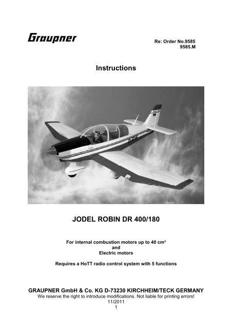
Instructions<br />
JODEL ROBIN DR 400/180<br />
For internal combustion motors up to 40 cm³<br />
and<br />
Electric motors<br />
Re: Order No.9585<br />
9585.M<br />
Requires a HoTT radio control system with 5 functions<br />
GRAUPNER GmbH & Co. KG D-73230 KIRCHHEIM/TECK GERMANY<br />
We reserve the right to introduce modifications. Not liable for printing errors!<br />
11/2011<br />
1
Specification<br />
Wingspan about 2200 mm<br />
Fuselage length without spinner about 1640 mm<br />
wing area about 84 dm²<br />
Tailplane area about 18.4 dm²<br />
Wing area about 102.4 dm²<br />
All-up weight depending on equipment about 9000 g<br />
EWD 0-0.5 degrees<br />
Centre of gravity about 130-140 mm behind the leading<br />
edge<br />
Caution: This model is not a toy!<br />
If you do not have experience with such motorised models, please ask experienced<br />
model flyers for help. If the model is operated without the proper knowledge, injuries<br />
can result. Think of your health and safety!<br />
Important! Before you start the assembly!<br />
Even if you have already built lots of RC models, read these instructions through<br />
carefully and check the parts in the kit for completeness. A lot of effort was made to<br />
keep things as simple as possible without neglecting safety.<br />
Note on the covering sheet<br />
Because of strong changes in the weather (temperature, humidity, et cetera), folds<br />
can appear in the covering sheet. In rare cases, the components can even be<br />
warped. This lies in the nature of wood construction with covering sheet. This can be<br />
corrected as follows using a hair dryer like those available to model builders.<br />
Creases: Blow with hot air and rub with a soft cloth.<br />
Warped area: Gently twist the area against the direction of warping and smooth it<br />
out again using hot air.<br />
Caution! Never use more heat than is absolutely necessary. If the iron is too hot, the<br />
covering sheet will melt and holes will form.<br />
The extensively pre-fabricated model can be built in a very short time. However, the<br />
remaining steps are important and have to be carried out with care. Doing this work<br />
properly determines whether the model will have the prescribed rigidity and flight<br />
characteristics; so please work slowly and precisely!<br />
When putting screws into wood, apply a little casein glue to keep them from<br />
loosening: Squirt casein glue into the drill hole and screw in the screw.<br />
Tips on building the model<br />
• Before assembling the model, it is essential to read the construction diagram and<br />
the instructions all the way through. When using tools, be aware of the possible<br />
dangers.<br />
GRAUPNER GmbH & Co. KG D-73230 KIRCHHEIM/TECK GERMANY<br />
We reserve the right to introduce modifications. Not liable for printing errors!<br />
11/2011<br />
2
• Use only suitable cables that are adequate for the electrical currents that occur<br />
during operation.<br />
• Set up the receiver aerial as far as possible away from the cables carrying the<br />
operating current (at least 3 cm).<br />
• Clean residual grease from all connections that are to be glued. This could be<br />
done, for example, through sanding and using a non-relubricating cleaning<br />
solution. The same goes for the surfaces to be painted, in order to make sure that<br />
the paint sticks. Before gluing parts, always roughen the corresponding surfaces<br />
(especially for GFR fuselages) carefully with fine sandpaper and de-grease them<br />
thoroughly, for example with acetone. Otherwise, adequate adhesion is not<br />
assured.<br />
Other required accessories<br />
Internal combustion motor and accessories<br />
Recommendations for internal combustion motor<br />
Motor<br />
Order No.<br />
OS MAX FS 200 S<br />
2728<br />
Petrol motor<br />
GT 33<br />
2772<br />
Recommendations for electric motor<br />
Electric<br />
motor<br />
Order No.<br />
COMPACT<br />
740 Z<br />
7780<br />
Propeller<br />
Order No.<br />
45 x 25 cm<br />
1326.22x10<br />
Capacity Silencer<br />
Propeller<br />
cm³ Order No. Order No.<br />
32.4 2728.33<br />
Motor accessory<br />
(included)<br />
1318.45.25<br />
33 2772.33 45x25 cm<br />
1314.18x10“<br />
Drive battery<br />
Order No.<br />
LiPo 5/5200<br />
11.1V/5.2Ah<br />
9752.5<br />
Speed<br />
controller<br />
Order No.<br />
COMPACT<br />
CONTROL<br />
90S<br />
7228<br />
Radio control system<br />
It must have at least 5 control functions and 10 servos. Furthermore, the transmitter<br />
must be capable of servo rotation reversal.<br />
Particularly recommended: Computer System MC-22s to MC-24. Servos with<br />
standard dimensions can be installed.<br />
As receiver battery, we recommend: two GRAUPNER 5N-5000 NiMH Order No.<br />
98903.5, which must always be serviced well before and after flight operations,<br />
meaning that the battery has to be charged and discharged again multiple times until<br />
the specified capacity has been reached.<br />
GRAUPNER GmbH & Co. KG D-73230 KIRCHHEIM/TECK GERMANY<br />
We reserve the right to introduce modifications. Not liable for printing errors!<br />
11/2011<br />
3
Connecting the two ailerons and the landing flap servos to the receiver requires four<br />
spark suppression filters, Order No. 1040 or one collapsible ferrite core, Order No.<br />
98516.1 with four extension cables Order No. 3935.18.<br />
The two aileron servo cables must each be extended with an extension cable Order<br />
No. 935.75, the two landing flap servo cables with Order No. 3935.32, the two<br />
elevator servos with Order No. 3935.105, the throttle servo with Order No. 3935.18,<br />
the nose gear servo with Order No. 3935.11, the aero-tow coupling servo with Order<br />
No. 3935.32. Two Order No. 7907.2 are used as servo control arms.<br />
Receiver and battery: Store in foam material.<br />
Any servo of standard size and an adjusting power of about 50 Ncm can be installed.<br />
Adhesives<br />
Epoxy glue, such as "UHU plus schnellfest," Order No. 962<br />
Epoxy glue, such as "UHU plus endfest 300," Order No. 950.43<br />
"UHU Holzleim express" casein glue, Order No. 958.60<br />
"UHU hart" glue, Order No. 534.35<br />
Fast-setting (cyano-acrylate) glue, such as Order No. 5821<br />
Fast-setting (cyano-acrylate) glue, such as Order No. 5822<br />
Thread lock fluid, such as Order No. 952<br />
Accessories for operation (not included)<br />
Fuel, depending on the motor petrol/oil mixture (see instructions for the motor used)<br />
Fuel tubing, petrol, such as Order No. 1325.2<br />
Manual fuel pump, such as Order No. 6870<br />
Ignition battery, Order No. 8716.5<br />
Charger cables and chargers for electric aircraft<br />
Required tools (not included)<br />
Various (Phillips) screwdrivers, needle-nose pliers, flat-nose pliers, wire cutter, balsa<br />
knife or razor blade, various drills, pencil, felt marker, soldering iron with fine tip.<br />
Heat-shrink tubing, Order No. 3391.8<br />
Assembling the JODEL ROBIN DR 400/180<br />
Wings with undercarriage and tailplane<br />
GRAUPNER GmbH & Co. KG D-73230 KIRCHHEIM/TECK GERMANY<br />
We reserve the right to introduce modifications. Not liable for printing errors!<br />
11/2011<br />
4
Do not begin the assembly until you have familiarised yourself with the components<br />
and the individual construction stages. If you are not satisfied with any component,<br />
report it to your retailer before you start the construction process.<br />
Using sandpaper or sanding block, sand the control horns on the surfaces to be<br />
glued in order to achieve an adequate connection when gluing.<br />
As seen in the photos, unstick the slots for the GRP control horns, put a dab of glue<br />
into the slot, and push the control horn in until it stops.<br />
Wipe off any excess glue.<br />
Until the glue hardens, the servos are installed in the corresponding mounts and<br />
fastened into the wing or tailplane.<br />
Extend the servo cables using the corresponding extension cable and make sure<br />
they can not come loose, for example with a piece of heat-shrink tubing or a drop of<br />
fast-setting glue. Using the RC system, bring the servos in the middle position and<br />
install the servo levers.<br />
GRAUPNER GmbH & Co. KG D-73230 KIRCHHEIM/TECK GERMANY<br />
We reserve the right to introduce modifications. Not liable for printing errors!<br />
11/2011<br />
5
Fasten the servo to the attachment block using the screws included with the servos.<br />
To do so, insert the rubber grommets with the brass hollow rivets, collar downward,<br />
into the servo flange. For drilling Ø 1.5 mm holes for the screws, the hollow rivets can<br />
be used as a drilling template. To make it easier to push them in,<br />
the hollow rivets can be placed onto a screwdriver of the proper size.<br />
Now the servo cables are pulled into the wing halves and tailplane halves using a<br />
thin string. Just behind the connector, tie the string to the cable and pull it in so that it<br />
comes out the wing root.<br />
With servo and rudder in neutral position, screw together the lengths of the rods for<br />
the ailerons, landing flaps, and elevators, adjust them, and use thread lock fluid (such<br />
as UHU schraubensicher) and lock nuts to secure them against loosening.<br />
GRAUPNER GmbH & Co. KG D-73230 KIRCHHEIM/TECK GERMANY<br />
We reserve the right to introduce modifications. Not liable for printing errors!<br />
11/2011<br />
6
As shown in the photo, secure the hinges for the landing flaps using heat-shrink<br />
tubing.<br />
On the underside of the wings, there are markings indicating where the flap hinges<br />
can be screwed in. Make sure that the axes of rotation of the hinges are all the same<br />
distance from the trailing edge of the wing.<br />
As shown in the photo at the left, a screw is used to<br />
fix the hinges in place; then use an engineer's square or geometric protractor for<br />
alignment with the trailing edge, and fasten the hinges with two more screws. Now<br />
push the landing flaps up against the wings and tape them in place temporarily; align<br />
them, and fasten them with screws.<br />
Screw the pushrods together as shown in the following photos.<br />
GRAUPNER GmbH & Co. KG D-73230 KIRCHHEIM/TECK GERMANY<br />
We reserve the right to introduce modifications. Not liable for printing errors!<br />
11/2011<br />
7
In the next step, use your fingers to feel for the slot for the landing gear wire, and<br />
melt it free with a hot soldering iron.<br />
Now place the leg of the undercarriage into the slot, to mark the attachment points of<br />
the two tabs and the wheel fairing support block.<br />
Drill pilot-holes in the wings for the retaining screws; then screw the tabs and the<br />
wheel fairing support block to the wing.<br />
GRAUPNER GmbH & Co. KG D-73230 KIRCHHEIM/TECK GERMANY<br />
We reserve the right to introduce modifications. Not liable for printing errors!<br />
11/2011<br />
8
For the wire undercarriage units you will need to file away the inside of the two<br />
fairings a bit. When installing the fairings, make sure that the wheel covers face<br />
outwards. The wheels can now be attached to the axles using collets and grub<br />
screws. Apply UHU thread-lock fluid to the grub screws to prevent them working<br />
loose. Loosen the grub screw at the front of the shock absorbing strut, loosen, and<br />
push the wheel axle to the other side. Re-tighten the grub screw.<br />
The wheels and wheel fairings must be aligned exactly parallel with the fuselage<br />
centreline.<br />
The final stage on the wing is to install the landing searchlight.<br />
As shown in the following photographs, fit the two LEDs in the white plastic holder<br />
and secure them with a little UHU Power all-purpose adhesive.<br />
Trim the outside edges of the plastic holder so that it fits in the recess in the wing.<br />
Route the connecting leads of the two diodes to the root rib using a piece of thread,<br />
and run them out of the drilled access hole. The plastic holder can now be glued in<br />
using UHU Power all-purpose adhesive. Fix the glazing to the wing using clear<br />
adhesive tape.<br />
GRAUPNER GmbH & Co. KG D-73230 KIRCHHEIM/TECK GERMANY<br />
We reserve the right to introduce modifications. Not liable for printing errors!<br />
11/2011<br />
9
Fuselage with tailplane, vertical stabiliser, and nose gear<br />
The vertical stabiliser can either be glued permanently to the fuselage or fastened<br />
removably using four screws.<br />
Only the fastening of the vertical stabiliser using screws is described.<br />
Before putting in the screws, the two extension cables for the two elevator servos<br />
must be pulled into the fuselage.<br />
Use the Ø 12 mm aluminium tube to put the horizontal stabiliser onto the fuselage to<br />
test the fit; the two extension cables must be routed through the openings of the<br />
horizontal stabiliser on the right and left.<br />
The two halves of the tailplane must be attached to the fuselage using the Ø 12 mm<br />
aluminium tube and four M3x16 Allen screws each.<br />
GRAUPNER GmbH & Co. KG D-73230 KIRCHHEIM/TECK GERMANY<br />
We reserve the right to introduce modifications. Not liable for printing errors!<br />
11/2011<br />
10
Now the rudder is fastened to the horizontal stabiliser using steel wire. Assemble the<br />
pull cables as shown in the photo.<br />
Then attach the rudder servo to the servo plate at the front of the fuselage.<br />
As shown in the photo, install the pull cables to the servo lever and adjust them so<br />
that the rudder is in the centre position when the servo is in the centre position.<br />
As shown in the photo, fix the fairing support block to the nose gear using an M4<br />
Allen screw and nut.<br />
GRAUPNER GmbH & Co. KG D-73230 KIRCHHEIM/TECK GERMANY<br />
We reserve the right to introduce modifications. Not liable for printing errors!<br />
11/2011<br />
11
Fix the noseleg in the brackets by tightening the screw in the collet. Assemble the<br />
pull cables as shown in the photo.<br />
Here too, make sure that the nose gear is exactly in the neutral position when the<br />
servo is in the centre position. Later the nose gear steering servo and the rudder<br />
servo can be connected to the same receiver socket either using a Y-lead or via a<br />
mixer at the transmitter.<br />
As shown in the photos, the wheel fairing is attached to the support block using four<br />
self-tapping screws.<br />
The nosewheel can now be fitted onto the axle and secured using two collets, as<br />
already described for the main undercarriage.<br />
As with the ailerons and landing flaps, each of the rudder pushrods consists of two<br />
M3 clevises and nuts and one screw rods. The length of the two rods must be<br />
adjusted so that the elevators are at the centre position when the servo is in centre<br />
position. Before screwing in the two elevator servos, the connecting cables must be<br />
extended using suitable extension cables.<br />
Screw the aero-tow mechanism into the hole just behind the canopy, and apply UHU<br />
thread-lock fluid to prevent the coupling and nut from working loose.<br />
The aluminium part must be shortened enough so that the clevis can move freely;<br />
adjust the rods accordingly.<br />
GRAUPNER GmbH & Co. KG D-73230 KIRCHHEIM/TECK GERMANY<br />
We reserve the right to introduce modifications. Not liable for printing errors!<br />
11/2011<br />
12
It is best to operate the aero-tow release<br />
mechanism using a momentary switch<br />
mounted on the joystick. The servo travel<br />
must be set accordingly.<br />
Installing the tank and motor<br />
Assembling and installing the fuel<br />
tank<br />
Slip a piece of plastic tubing onto the fuel tank clunk pick-up. Push the free end of the<br />
fuel tubing onto one of the tubes in the fuel tank stopper so that the pick-up will be able<br />
to move freely inside the tank later on without binding or jamming when the stopper is<br />
in place. Use a heat-gun or lighter to gently heat the free plastic tubes so that they can<br />
be bent easily. One tube should face down and will be used later to fill the tank; the<br />
other one points upward and serves later as the overflow when the tank is filled. Use<br />
pieces of tubing to extend the two tubes so that they reach to the top and bottom of the<br />
tank.<br />
Now push the tank stopper over the throat of the fuel tank, and tighten the Philips-head<br />
screw to fasten the stopper in place. It is important to tighten the screw so that the tank<br />
is completely sealed. This can be checked by holding the tank under water. Hold it<br />
under water and blow air into it. If the tank is sealed, there will be no air bubbles.<br />
To each stub tube projecting from the fuel tank, a length of fuel tubing is connected.<br />
Mark the tubes with a felt marker to show which runs to the motor, the overflow, and<br />
the filler.<br />
The tube from the clunk is then connected to the carburettor, while the overflow is run<br />
downward. The fuel filler tube can later be routed out through a drill hole in the motor<br />
bonnet. After filling, it should be sealed with a plug.<br />
The attachment block is fastened with two screws.<br />
GRAUPNER GmbH & Co. KG D-73230 KIRCHHEIM/TECK GERMANY<br />
We reserve the right to introduce modifications. Not liable for printing errors!<br />
11/2011<br />
13
As shown in the photo, connect/glue the tank and the throttle servo into the fuselage<br />
using the brackets. Depending on the motor used, the servo is installed to right or left<br />
of the tank.<br />
Installing the motor<br />
This section describes the installation of the OS MAX GT 33, but the procedure is the<br />
same for other engines.<br />
Four holes for the rubber damping elements have to be drilled into the firewall to<br />
match the particular engine.<br />
The centre of the motor is marked on the firewall. Drill Ø 6 mm holes to match the<br />
attachment holes for the engine.<br />
From the included aluminium pipe, cut off four pieces of 30 mm each. In each<br />
section, to the right and left, put on an aluminium bushing and screw the motor to the<br />
bulkhead as shown in the photo. Cut the protruding ends of the four bolts off flush<br />
with the nuts.<br />
The throttle rod is adjusted so that the carburettor is half open when the servo is in<br />
centre position. The servo travel must be adjusted so that the engine stops when the<br />
throttle stick and trim are at the full back position.<br />
GRAUPNER GmbH & Co. KG D-73230 KIRCHHEIM/TECK GERMANY<br />
We reserve the right to introduce modifications. Not liable for printing errors!<br />
11/2011<br />
14
Install the rods for the choke flap as shown in the photo. The end is angled so that it<br />
can be activated later through the opening in the engine bonnet. In so doing, make<br />
sure of the following. Do not let it get into the propeller arc.<br />
The silencer is attached to the motor using the included two bolts and seal.<br />
Depending on the motor used, it is necessary to cut or file openings in the engine<br />
bonnet where the silencer and spark plugs, et cetera, protrude. Position the engine<br />
bonnet on the fuselage in such a way that there is about 2 mm clearance between<br />
the spinner base plate and the front edge of the bonnet.<br />
To attach the engine bonnet to the fuselage, the four attachment points also have to be marked<br />
on the engine bonnet. To do so, cut four strips of scrap wood and drill a Ø 3 mm hole in each<br />
one as shown in the photo.<br />
Now each strip is fastened to the fuselage using an M3 Allen screw and taped in<br />
place as shown in the photo.<br />
Unscrew the Allen screws, then push up the engine bonnet so that it moves under<br />
the strips and the spinner base plate is about 1.5-2 mm from the engine bonnet. In<br />
this position, mark the four attachment points on the engine bonnet.<br />
GRAUPNER GmbH & Co. KG D-73230 KIRCHHEIM/TECK GERMANY<br />
We reserve the right to introduce modifications. Not liable for printing errors!<br />
11/2011<br />
15
The engine bonnet is attached with four Allen screws as shown in the photos.<br />
Installation of the electric motor<br />
The electric motor is attached to the bulkhead using the included motor bulkhead,<br />
bolts, nuts, cylindrical aluminium bushings, and sections of the aluminium pipe.<br />
GRAUPNER GmbH & Co. KG D-73230 KIRCHHEIM/TECK GERMANY<br />
We reserve the right to introduce modifications. Not liable for printing errors!<br />
11/2011<br />
16
The distance between bulkhead and spinner ground plate should be about 160 mm.<br />
Accordingly, four pieces of equal length must be cut from the aluminium pipe.<br />
As shown in the photo, the motor then rests upon four stilts. The four hexagonal bolts<br />
must be cut off flush with the nuts.<br />
Depending on the electric motor used, mark the fastening points on the motor<br />
bulkhead and attach the electric motor.<br />
The speed controller for the electric motor is fastened to the bulkhead as shown in<br />
the photo.<br />
Cockpit canopy<br />
Glue the seat backs and pilot figure in the proper positions as shown in the following<br />
photos.<br />
GRAUPNER GmbH & Co. KG D-73230 KIRCHHEIM/TECK GERMANY<br />
We reserve the right to introduce modifications. Not liable for printing errors!<br />
11/2011<br />
17
The parts should be affixed using double-sided tape, such as Order No. 2904.<br />
The cockpit canopy is attached to the frame using small pan-head self-tapping<br />
screws. A strip of tape all around has proven to be a good way to ensure that the<br />
cockpit canopy fits the frame uniformly.<br />
The final work on the model consists of fitting and gluing the navigation lights, hatch<br />
covers, and aerials.<br />
Balancing the Jodel ROBIN DR 400/180<br />
The model (with the fuel tank empty for an internal combustion version or with the<br />
drive batteries inserted for an electric version) should supported to the right and left<br />
at a point about 130 - 140 mm aft of the leading edge of the wing, ideally in inverted<br />
flight position. If the centre of gravity is correct, the model should balance out<br />
horizontally or with the nose pointing slightly downward. If necessary, adjust the<br />
centre of gravity by shifting the position of the receiver batteries. Before flying the<br />
aircraft, set the transmitter trims to centre and ensure that all the control surfaces are<br />
also exactly centred (in neutral position).<br />
Rudder deflection for normal flying<br />
Ailerons25 mm up and 9 mm down<br />
Elevators 20 mm up and down<br />
Rudder 35 mm left and right<br />
Landing flapsTake-off15 mm down<br />
Landing60 mm down<br />
GRAUPNER GmbH & Co. KG D-73230 KIRCHHEIM/TECK GERMANY<br />
We reserve the right to introduce modifications. Not liable for printing errors!<br />
11/2011<br />
18
We recommend that you set exponential values of 30% at the transmitter.<br />
Important:<br />
When assembling the rods, always take care to ensure that they move freely and can<br />
move through their entire controllable path - including trim travel - and are not<br />
mechanically impeded.<br />
When the joystick moves to the right, the rudder must turn to the right (left stick/left<br />
rudder). When the elevator stick is pulled back, toward your stomach, the elevators<br />
must deflect upward (stick forward = elevators down). If the aileron stick is moved to<br />
the right, the right aileron should move upward; the left aileron downward. When the<br />
throttle stick is pushed forward, the motor must run at full power; if the throttle stick<br />
and trim are moved back to their end-points, the engine must stop. If the trim travel is<br />
moved all the way back, the motor must stop. The landing flaps are best activated via<br />
a three-position switch.<br />
All that remains is to wish you many hours of happy flying your JODEL ROBIN DR<br />
400/180.<br />
Your Team !<br />
GRAUPNER GmbH & Co. KG D-73230 KIRCHHEIM/TECK GERMANY<br />
We reserve the right to introduce modifications. Not liable for printing errors!<br />
11/2011<br />
19
Safety notes and warnings<br />
Regarding motorized aircraft models with internal combustion engines<br />
• Before you first attempt to fly the model, it is essential to carefully read all<br />
the operating and assembly instructions.<br />
• These safety notes are part of these instructions and must be stored<br />
carefully with the operating instructions and, if the model is passed on to<br />
others, they must also be passed on to the next user.<br />
• Motorised models are very demanding and dangerous objects and require<br />
that the user have great expertise, skill, and a sense of responsibility.<br />
• Motorised models are not suitable for persons under 18 years of age.<br />
• They may be operated only under the instruction and supervision of an<br />
adult who is familiar with the attendant hazards.<br />
• The operator of the model must be in full possession of his or her bodily<br />
and mental faculties. As with car driving, operating a model aircraft under<br />
the influence of alcohol or drugs is not permissible under any<br />
circumstances.<br />
• Radio controlled aircraft models may be used only for the purpose intended<br />
by the manufacturer; meaning not as a sporting device designed to carry<br />
people. Any other use is forbidden.<br />
• A model can only work properly and fulfil your expectations if it is built or<br />
assembled with the greatest of care and in accordance with the assembly<br />
instructions. Independent changes in design or materials are not permitted.<br />
To avoid injuring people and damaging property, it is essential to be careful<br />
and thoughtful when operating your model. Nobody would climb into a fullsize<br />
sports aircraft and attempt to fly it without undergoing training<br />
beforehand. Model flying is also something that has to be learned! We<br />
suggest that you ask an experienced model flyer for help, or join a model<br />
club or model flight training school. Your local model shop and the<br />
specialist magazines are excellent sources of information.<br />
• Always observe the information on the centre of gravity and on control<br />
surface deflection! The model must be adjusted accordingly.<br />
• Radio control system: Make sure the frequency used is vacant. Do not<br />
switch on until you are sure! Check the RC system frequently; it too is<br />
subject to wear. Radio interference caused by unknown sources can occur<br />
at any time without warning. Your model will then be uncontrollable and<br />
completely unpredictable. Never leave your radio control system<br />
•<br />
unattended, as another person might pick it up and try to use it. To ensure<br />
proper operation of your RC system, make sure that the batteries are kept<br />
fully charged.<br />
Do not ignore warnings! They refer to materials and situations, which, if<br />
ignored, can - in extreme cases - result in fatal injury or permanent damage.<br />
• You alone are responsible for the safe operation of your model and motor.<br />
• Questions regarding the safe operation of model and motor can be<br />
answered by your retailer.<br />
• Propellers and all rotating parts that are powered by a motor pose a<br />
constant risk of injury. Do not touch them with any part of your body! For<br />
example, a propeller spinning at high speed cut off a finger!<br />
GRAUPNER GmbH & Co. KG D-73230 KIRCHHEIM/TECK GERMANY<br />
We reserve the right to introduce modifications. Not liable for printing errors!<br />
11/2011<br />
20
• Always keep well clear of the rotational plane of the propeller! You never<br />
know when some part may come loose and fly off at high speed and with<br />
great energy, hitting you or a third party. Make sure that no other object can<br />
come into contact with the rotating propeller.<br />
• Be careful with loose clothing, such as scarves, loose shirts, et cetera: They<br />
can be sucked in by the propeller stream and get in the way of the propeller<br />
itself.<br />
• If there are passers-by or spectators at your flying site, make sure that they<br />
are aware of the dangers inherent in your activity before you start the<br />
motor, and insist that they keep a safe distance away (at least 5 m).<br />
• Model aircraft may be flown only at "normal" outside temperatures,<br />
meaning in a range of - 5º C to + 35º C; more extreme temperatures could<br />
lead to changes, such as battery capacity and material characteristics, et<br />
cetera.<br />
• Model fuel is poisonous! Do not let it come into contact with eyes or mouth!<br />
Store only in clearly marked containers out of the reach of children.<br />
• Never run the motor in closed rooms, such as basement, garage, et cetera.<br />
Model motors also produce deadly carbon monoxide gas.<br />
• Operate only outdoors!<br />
• Adhesives and paints contain materials which may be hazardous to health<br />
under certain circumstances. You should therefore observe the notes and<br />
warnings supplied by the manufacturers of these materials.<br />
• Model fuel is highly flammable and combustible; keep away from open<br />
flames, excessive heat, any sources of sparks or other things that could<br />
lead to ignition. Do not smoke in the direct vicinity of fuel or fuel fumes.<br />
• During operation, a model motor develops a great deal of heat. Motor and<br />
shock absorbers are therefore very hot during operations and for a while<br />
afterwards. Touching them can result in serious burns. Careful when<br />
making adjustments! Wear protective gloves! In extreme cases, even fires<br />
can be caused.<br />
• While operating the motor, not only poisonous and hot exhaust emanates<br />
from the exhaust pipe but also very hot liquid combustion residue, which<br />
can result in burns.<br />
• After operation, remove residual fuel from the tank and motor.<br />
• Before and after you operate your model, always carefully check it and<br />
everything attached to it (such as propeller, rudder linkages, rudders, et<br />
cetera) for possible damage. If you find a fault, do not fly the model until you<br />
have corrected it.<br />
• The motor is started with an electric starter, which may be equipped with an<br />
adapter that fits the model. As an alternative start aid for fixed-wing models, for<br />
example, a wooden dowel with a piece of watering hose attached can be used.<br />
• During operation, model motors may develop noise far greater than 85 dB<br />
(A); always wear protection for your ears. Never start motors without a<br />
silencer. However, even with a silencer, model motors can disturb<br />
neighbours. Don’t run motors when people expect peace and quiet.<br />
GRAUPNER GmbH & Co. KG D-73230 KIRCHHEIM/TECK GERMANY<br />
We reserve the right to introduce modifications. Not liable for printing errors!<br />
11/2011<br />
21
• If the propeller is turning while the model is standing on sandy ground, for<br />
instance, the propeller can suck up sand and dust and hurl it around, and it<br />
could get in people's eyes. Wear protective goggles!<br />
• Take care that the spark plug clip and the lead can not get tangled in the<br />
turning propeller or other rotating parts. Check the throttle linkage, too.<br />
• Take particular care when carrying the model with the engine running. Hold<br />
the rotating parts well away from you!<br />
• Always keep an adequate supply of fuel in the tank. Never continue to fly<br />
the model until all the fuel is used up.<br />
• Never fly directly over people.<br />
• Never fly directly towards people.<br />
• Make sure to keep a safe distance from residential areas: at least 1.5 km “as<br />
the crow flies”. It is always best to join a club and fly at the approved model<br />
flying site. Always keep well clear of high-tension overhead cables.<br />
• Whenever working on the engine, make sure that you have secure footing,<br />
and always hold the model securely.<br />
• When starting and landing, the take-off and landing strips should be kept<br />
free of unauthorised people and movable obstacles.<br />
• The model aircraft must be kept constantly in sight during the entire flight. It<br />
must always give way to manned aircraft.<br />
• Never operate your aircraft from public roads, squares, squares, school<br />
playgrounds, parks, or sports grounds, et cetera, and ensure that you are<br />
always in full control of the model.<br />
• To ensure that you can stop your engine at any time, the throttle must be<br />
adjusted so that the carburettor barrel closes completely when the throttle<br />
stick and trim are moved to their end points. If this does not work, pinch the<br />
fuel line between your fingers or pull off the connecting tube to the tank.<br />
Never try to stop the engine by grasping the flywheel, propeller, or spinner!<br />
• All model fliers should take care to ensure that the public safety and order,<br />
especially that of people and property, as well as orderly flying operations,<br />
are not endangered or disturbed.<br />
• In legal terms, model aircraft are classed as aircraft and as such are subject<br />
to legal regulations and restrictions that must be observed.<br />
• Our brochure “Modellflugrecht, Paragrafen and mehr” (Model Aviation Law,<br />
Legal Requirements and more), Order No. 8034.02 contains a summary of<br />
all these rules, and your local model shop should also have a copy which<br />
you can read. Models powered by internal combustion engines may only be<br />
flown with the landowner’s permission, and insurance is mandatory. There<br />
are also regulations concerning your radio control system that must be<br />
observed.<br />
• These notes are intended only to make you aware of the many dangers and<br />
hazards that can arise if you work carelessly or irresponsibly. If you take<br />
reasonable care, model flying is a highly creative, instructive, and relaxing<br />
pastime.<br />
• The extensively pre-fabricated model can be built in a very short time.<br />
However, the remaining steps are important and have to be carried out with<br />
care. Doing this work properly determines whether the model will have the<br />
GRAUPNER GmbH & Co. KG D-73230 KIRCHHEIM/TECK GERMANY<br />
We reserve the right to introduce modifications. Not liable for printing errors!<br />
11/2011<br />
22
prescribed rigidity and flight characteristics; so please work slowly and<br />
precisely!<br />
Important safety notes<br />
You have acquired a kit that can be assembled into a fully working RC model when<br />
fitted out with suitable accessories. However, GRAUPNER has no control over<br />
whether you observe the instructions for the installation and operation of the model or<br />
the use and maintenance of the associated components. For this reason<br />
GRAUPNER assumes no liability for loss, damage, or costs, which are incurred due<br />
to the incorrect use of our products or due to improper behaviour on the part of the<br />
user, or which are connected with such operation in any way. Unless otherwise<br />
prescribed by binding law, the obligation of GRAUPNER to pay compensation for any<br />
reason whatsoever (including personal injury, death, damage to buildings, damage<br />
due to loss of business or turnover, interruption of business, or other direct or indirect<br />
consequent damage) stemming from the operation of the model is excluded.<br />
The total liability in all cases and under all circumstances is limited to the amount of<br />
money that you actually paid for this model.<br />
This model is started up and operated at the sole and exclusive risk of the<br />
operator. To avoid injuring people and damaging property, it is essential to be<br />
careful and thoughtful when operating your model.<br />
According to the new regulation of §103 Paragraph 3 of the LuftVZO (German<br />
Aviation Approvals Office), all model aircraft - whether slow flyer, park flyer, glider, or<br />
model aircraft propelled by any form of power plant - must be insured before the<br />
model is operated. Therefore, you should purchase special RC model liability<br />
insurance. Your local model shop will be glad to advise you.<br />
These safety notes must be kept in a safe place, and, if you ever sell the model, must<br />
be passed on to the buyer.<br />
Manufacturer’s declaration:<br />
If material defects or manufacturing faults should arise in a product distributed by us<br />
in the Federal Republic of Germany and purchased by a consumer (§ 13 BGB), we,<br />
<strong>Graupner</strong> GmbH & Co. KG, Henriettenstraße 94-96 D-73230 Kirchheim/Teck,<br />
Germany, acknowledge the obligation to correct those defects within the limitations<br />
described below.<br />
The consumer is not entitled to make claims under this manufacturer’s declaration if<br />
the failure in the usability of the product is due to natural wear, use under competition<br />
conditions, incompetent or improper use (including incorrect installation), or external<br />
influences.<br />
This manufacturer’s declaration does not affect the consumer’s legal or contractual<br />
rights regarding defects arising from the purchase contract between the consumer<br />
and the vendor (dealer).<br />
Extent of the guarantee<br />
If a claim is made under guarantee, we undertake at our discretion to repair or<br />
replace the defective goods. We will not consider further claims, especially for<br />
GRAUPNER GmbH & Co. KG D-73230 KIRCHHEIM/TECK GERMANY<br />
We reserve the right to introduce modifications. Not liable for printing errors!<br />
11/2011<br />
23
eimbursement of costs relating to the defect (such as installation / removal costs)<br />
and compensation for consequent damages unless they are allowed by statute. This<br />
does not affect claims based on legal regulations, especially according to product<br />
liability law.<br />
Guarantee requirements<br />
The purchaser is required to make the guarantee claim in writing and must enclose<br />
original proof of purchase (such as invoice, receipt, delivery note) and this guarantee<br />
card. The defective goods must be sent to us at the purchaser's own cost, using the<br />
address stated above.<br />
The purchaser should state the material defect or manufacturing fault or the<br />
symptoms of the fault in as accurate a manner as possible so that we can check<br />
whether our guarantee obligation is applicable.<br />
The goods are transported from the consumer to us and from us to the consumer at<br />
the risk of the consumer.<br />
Duration of validity<br />
This declaration only applies to claims made to us during the claim period as stated<br />
in this declaration. The claim period is 24 months from the date of purchase of the<br />
product by the consumer from a dealer in the Federal Republic of Germany (date of<br />
purchase). If a defect arises after the end of the claim period, or if the evidence or<br />
documents required according to this declaration in order to make the claim valid are<br />
not presented until after this period, then the consumer forfeits any rights or claims<br />
from this declaration.<br />
Limitation by lapse of time<br />
If we do not acknowledge the validity of a claim based on this declaration made<br />
within the claim period, all claims based on this declaration expire after six months<br />
from the time of claim, but not before the end of the claim period.<br />
Applicable law<br />
This declaration, and the claims, rights and obligations arising from it, are based<br />
exclusively on the applicable German Law, without the norms of international private<br />
law, and excluding UN retail law.<br />
The following items must be observed:<br />
• Before you fly the model, check that the radio control system is working reliably,<br />
and that all connections are secure.<br />
• If you intend to use dry cells as a power supply, please note that they must never<br />
be recharged. Only rechargeable batteries can be re-charged.<br />
• The batteries must be charged, and the range of the radio control system must<br />
have been checked. In particular, the transmitter and receiver batteries must be<br />
charged before each take-off.<br />
GRAUPNER GmbH & Co. KG D-73230 KIRCHHEIM/TECK GERMANY<br />
We reserve the right to introduce modifications. Not liable for printing errors!<br />
11/2011<br />
24
• Ensure that the channel you intend to use is not already in use. Never fly the<br />
model if you are not certain that your channel is free.<br />
• Observe the instructions and information regarding your radio control system and<br />
accessories.<br />
• Ensure that the servos are not mechanically obstructed at any point in their travel.<br />
• Dry cells and rechargeable batteries must never be short-circuited.<br />
• Remove all batteries before transporting and storing the model.<br />
• Do not subject the model to intense humidity, heat, cold, or to dirt.<br />
• Protect the model and RC equipment against damage during transport.<br />
Pre-flight check<br />
Check for correct functioning and range before every flight. To do so, screw in the<br />
transmitter aerial and extend it fully. Then switch on the transmitter, followed by the<br />
receiver. At an appropriate distance, make sure that all the control surfaces are<br />
working properly and deflecting in the correct direction.<br />
Repeat the check with the motor running, while someone holds the model securely<br />
for you.<br />
The first time you control a model aircraft, it is best to ask an experienced person to<br />
help you with the pre-flight check and during the first few flights.<br />
Care and maintenance<br />
• Clean the model carefully after every flight. Also remove any dirt from the<br />
propeller. Clean the model and the RC components using suitable cleaning<br />
agents only. Ask your model shop for information.<br />
• If the model is not to be operated for a considerable time, all the moving parts<br />
must be cleaned and re-lubricated.<br />
GRAUPNER GmbH & Co. KG D-73230 KIRCHHEIM/TECK GERMANY<br />
We reserve the right to introduce modifications. Not liable for printing errors!<br />
11/2011<br />
25