July 2010 - Glenair, Inc.
July 2010 - Glenair, Inc.
July 2010 - Glenair, Inc.

Create successful ePaper yourself
Turn your PDF publications into a flip-book with our unique Google optimized e-Paper software.
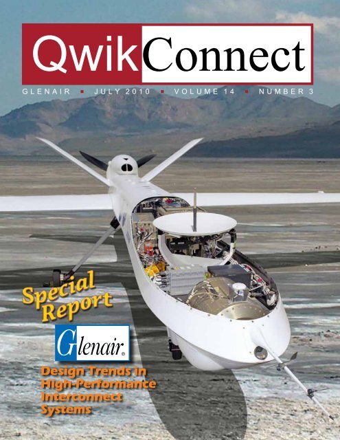
QwikConnect<br />
G L E N A I R n J u L y 2 0 1 0 n V O L u M E 1 4 n N u M B E R 3<br />
Design Trends in<br />
High-Performance<br />
Interconnect<br />
Systems
This issue of QwikConnect is about change.<br />
It’s about technology trends in commercial<br />
and military markets—everything from<br />
the increased use of miniaturized, unmanned<br />
systems in aerospace to the growth of high<br />
speed and high-bandwidth applications in the<br />
IT industry. Specifically it is about technology<br />
trends in the connectors, cables and<br />
other components used to<br />
interconnect cutting-edge<br />
electronic technologies in<br />
high-reliability industries.<br />
We’re all familiar with emerging<br />
“future soldier” systems such as Land Warrior.<br />
We all know what a Predator drone is and what<br />
it is used for. Satellites? Medical robots? The<br />
Mars Rover? Check, check and check. But how<br />
conversant are we with the important trends and<br />
latest inventions in the connector technologies<br />
that serve these systems? Could you, for<br />
example, describe the evolution in connector<br />
packaging to meet the changing needs of the<br />
down-hole drilling and well-logging industry? If<br />
you answered no, then you’ll want to read on<br />
as QwikConnect discusses the most important<br />
trends in connector design for defense,<br />
aerospace and other high-reliability applications.<br />
Five Key Trends, Plus a Few Surprises<br />
Change is inevitable, except, as comedian<br />
Gallagher once observed, from a vending<br />
machine. The evolution of ever more<br />
sophisticated electronic equipment, especially<br />
in military applications, has led inevitably to<br />
changes in connector design and packaging.<br />
The ongoing pursuit of miniaturization, our first<br />
category, has led to numerous evolutions and<br />
inventions. A common application type, such<br />
as high-reliability wire-to-board connectors,<br />
2<br />
QwikConnect<br />
Design Trends in Interconnect Systems<br />
illustrates the ongoing evolution in connector<br />
size and density to meet the demands for<br />
space-saving interconnections in<br />
OEM systems. Interestingly,<br />
these smaller, higher density<br />
interconnects still have to<br />
meet extremely high<br />
requirements<br />
for vibration,<br />
shock,<br />
temperature tolerance,<br />
corrosion resistance and so on. As Victor<br />
Hugo once said, “many great actions<br />
are committed in small struggles”. In our<br />
industry, it’s apt to say some of the<br />
greatest design work and innovation<br />
has been accomplished in the pursuit<br />
of small results.<br />
D-Subminiature Connector<br />
Contacts on 0.109 <strong>Inc</strong>h Spacing<br />
Micro-D Connector<br />
Contacts on 0.050 <strong>Inc</strong>h Spacing<br />
Nano Connector<br />
Contacts on 0.025 <strong>Inc</strong>h Spacing<br />
The second interconnect<br />
design trend we will explore<br />
is the accelerated use of<br />
composite thermoplastics in<br />
high-reliability systems. No better example<br />
QwikConnect n <strong>July</strong> <strong>2010</strong>
can be found than in systems, such as the<br />
Boeing 787 Dreamliner, that have made acrossthe-board<br />
commitments to replace heavy metal<br />
materials with lightweight composite plastics.<br />
Once used only in isolated and non-structural<br />
roles, composites now enjoy full-scale use<br />
throughout the most innovative commercial<br />
and military airframe applications. The principal<br />
reason, of course, is weight savings. Given the<br />
cost of available fuels, OEM manufacturers now<br />
calculate the total cost of system operation<br />
and have determined that selecting<br />
lighter weight composites can give their<br />
QwikConnect n <strong>July</strong> <strong>2010</strong><br />
platforms a<br />
competitive<br />
advantage compared to<br />
heavier, metal-only systems.<br />
The Restriction of use of<br />
certain Hazardous Substances<br />
(RoHS) states that certain types<br />
of equipment, primarily consumer<br />
electronic products such as personal<br />
computers and cell phones, shall not<br />
contain specified “hazardous substances.”<br />
<strong>Glenair</strong> interconnect components are<br />
specifically intended for use in military,<br />
defense, security, aerospace, naval,<br />
transportation and other applications that<br />
are exempt from this standard. The RoHS<br />
directive is, nevertheless, of great interest<br />
in our industry and is being increasingly<br />
specified even in applications that are<br />
explicitly exempt from the requirement. For<br />
most interconnect applications, attention<br />
to RoHS requirements falls into two areas,<br />
the use of leaded solder materials in<br />
certain assembly processes and Cadmium<br />
in selected plating processes. In the later<br />
category, <strong>Glenair</strong> has taken steps to develope<br />
a number of new plating technologies that still<br />
meet durability, temperature and corrosion<br />
resistance benchmarks while satisfying<br />
the RoHS directive. Cadmium reduction or<br />
elimination is another important trend. We’ll look<br />
at these important developments in the third<br />
section of our “trends” issue.<br />
Electromagnetic interference is the bane of a<br />
cable engineer’s existence. In fact, the pursuit<br />
of sensible approaches to resolve EMI and<br />
EMP challenges in interconnection systems is<br />
the number one challenge faced in many highreliability<br />
interconnect systems. Electromagnetic<br />
Interference (EMI) is conducted, radiated<br />
or magnetically induced voltage that<br />
degrades, obstructs, or repeatedly interrupts<br />
the performance of electronic equipment.<br />
Interconnect technology innovations, such as<br />
improved shielding materials, advanced EMI<br />
filter connectors and new conductive surface<br />
finish technologies are all employed in cuttingedge<br />
EMC (Electromagnetic Compatibility)<br />
interconnect cable designs. We’ll explore the full<br />
range of these technologies in the fourth section<br />
of our article.<br />
Avionic and other civilian/military vehicle<br />
data transfer systems are growing increasingly<br />
complicated—the number of data paths, data<br />
rates and the quantity and sophistication of<br />
subsystems continue to escalate. In addition<br />
to transmission speed, accuracy and reliability<br />
are tremendously important. Ethernet<br />
communication technology, with its huge<br />
installed base and history of reliability, is ideally<br />
suited for vehicles and other field applications.<br />
Although there are many MIL-STD-1553 bus<br />
architecture and data link systems in use,<br />
applications such as tactical radar require faster<br />
data rates than older architectures can deliver.<br />
As high-speed data systems become more<br />
prevalent in defense, aersospace, transportation<br />
and other high-reliability applications, the need<br />
for connector technology that can deliver the<br />
required performance in harsh, ruggedized<br />
settings becomes paramount. We explore this<br />
trend last (but not least!) in this special report.<br />
3
QwikConnect<br />
Circular Mil-Spec Type Connectors<br />
Circular MS type connectors are typically grouped into standard, miniature and subminiature families.<br />
These groupings reflect the packaging density and contact size, and also represent the evolution of connector<br />
roles over the past 70 years. The standard group includes the venerable 5015’s (<strong>Glenair</strong> Series IT and ITS)<br />
and the 28840 shipboard connector. Miniature circulars include the 26482 (<strong>Glenair</strong> Series IPT), while the<br />
MIL-DTL-38999 is the only significant subminiature circular. until recently, the evolution of MS type circulars,<br />
at least in terms of package size and layout density, had halted at the sub-miniature or “high density” 38999.<br />
But the <strong>Glenair</strong> Series 80 Mighty Mouse connector has effectively advanced miniaturization into the true<br />
“ultraminiature” category. The Series 80 Mighty Mouse Connector is designed for high-reliability commercial<br />
and aerospace/defense interconnect applications that require both robust environmental/EMI performance<br />
and reduced size and weight. The Series 80 Mighty Mouse Connector offers comparable performance<br />
to MIL-DTL-38999 Series interconnects with up to 71% weight and 52% size savings for similar contact<br />
counts. The major breakthrough trend to miniaturization was facilitated by placing smaller #23 contacts (to<br />
accept #22 to #28 wire) on contact spacing of .076 inch.<br />
4<br />
Connector Trends: Miniaturization<br />
Standard Subminiature Ultraminiature<br />
Miniature<br />
MIL-DTL-5015<br />
MIL-DTL-22992<br />
MIL-DTL-28840<br />
Series 80<br />
Mighty Mouse<br />
MIL-DTL-26482<br />
MIL-DTL-26500<br />
MIL-DTL-83723<br />
MIL-DTL-38999<br />
(Series III Shown)<br />
Series 80<br />
Mighty Mouse<br />
The smaller and lighter Mighty Mouse maintains the<br />
same approximate electrical and mechanical performance<br />
as larger and heavier military standard environmental<br />
connectors. Insert arrangements are available for as few as<br />
1 and as many as 130 contacts. The product series includes<br />
cable sets and backshells, all available with accelerated<br />
lead-times—many are packaged for immediate sameday<br />
shipment. #16 and #20 layouts are also available<br />
for higher current requirements and for coaxial contact<br />
accommodation. Custom layouts, such as might be required<br />
to accommodate a different gage or type of contact may<br />
be readily incorporated into existing shell/coupling designs.<br />
<strong>Glenair</strong> also offers the complete Mighty Mouse package in<br />
a rectangular version called the “Micro-Crimp.”<br />
QwikConnect n <strong>July</strong> <strong>2010</strong>
Rectangular I/O and Board-to-Wire Connectors<br />
Industry-Standard rectangular I/O and board-to-wire connectors include ARINC type rack and panel<br />
connector at one end of the size and density spectrum extending to nanominiature connectors on the other.<br />
The D-subminiature and the Micro-D complete the standard range from low to high density. The trend to<br />
miniaturization has been more rapid in rectangular connector packaging due to their more frequent application<br />
in Board-to-Wire and Board-to-Board level interconnections. The MIL-DTL-32139 Nanominaiture connector<br />
with its 0.025 inch contact spacing is the latest evolution in rectangular shaped connectors for board-level<br />
I/O applications. Featuring solid gold TwistPin contacts and aluminum, titanium or stainless steel shells, the<br />
Nanominiature is the smallest, yet remarkably robust, connector in the high-reliability industry. <strong>Glenair</strong> was one<br />
of the first interconnect manufacturers to qualify to the new MIL-DTL-32139 Nanominiature Mil-Spec for these<br />
precision-machined connectors that deliver both ultra high density and maximum weight and space savings.<br />
These high reliability ultra miniature interconnects are ideal for critical applications where size and weight<br />
restrictions preclude the use of larger connectors such as M24308 D-Subminiatures. Ideal for military and<br />
civilian applications of all types, the rugged contact system allows the nano connector to be used in the most<br />
demanding miniaturized applications. The <strong>Glenair</strong> Nano contact system consists of a TwistPin (a miniaturized<br />
version of the <strong>Glenair</strong> Micro-D TwistPin) and a tubular socket providing excellent durability and superior<br />
resistance to shock and vibration. Accommodating #30 or #32 AWG wire, Nano TwistPin contacts handle 1<br />
AMP current rating and 70 Volts AC RMS operating voltage.<br />
Standard<br />
ARINC (800)<br />
Nanominiature connectors are high reliability<br />
ultraminiature interconnects intended for critical<br />
applications where size and weight restrictions<br />
will not allow the use of larger connectors. Typical<br />
applications include miniaturized electronics<br />
boxes used in uAV’s, satellites, missile systems,<br />
and geophysical instruments. Contact spacing<br />
of 0.025 inches combined with a rugged contact<br />
system allow these nano connectors to be used in<br />
demanding environments where commercial-grade<br />
connectors should not be used. These high reliability<br />
ultra miniature interconnects are well suited for<br />
applications requiring both ultra high density as well<br />
as maximum weight and space savings.<br />
QwikConnect n <strong>July</strong> <strong>2010</strong><br />
Subminiature Micro Nano<br />
MIL-DTL-24308 MIL-DTL-83513 MIL-DTL-32139<br />
Series 79<br />
Nanominiature<br />
5
For many people, “plastic” means “cheap and<br />
breakable.” But when engineers search for new<br />
ways to enhance weight savings, corrosion<br />
resistance, shock and vibration dampening and<br />
stealth they immediately turn to plastic—the only<br />
alternative material capable of meeting, and beating,<br />
the established performance levels of aluminum,<br />
brass, titanium and steel.<br />
The name “plastic” refers to the ability to form<br />
or shape a material, or to the moldability a material<br />
adopts under forces such as pressure or heat.<br />
Engineers often use the term “polymer” when<br />
referring to plastic materials, because it more clearly<br />
describes how many (poly) chemical units (mers)<br />
combine in complex chains to create modern plastic<br />
resins. “Thermoplastics” are polymer materials that<br />
melt to a liquid when heated and form into a hard,<br />
dimensionally stable shape when cooled.<br />
Thermoplastic polymers are created by subjecting<br />
various chemical and petroleum-based ingredients<br />
to heat and pressure in sealed vessels. Specific<br />
chemical additives control how the polymer is<br />
formed and contribute to its performance in such<br />
areas as surface hardness and flame resistance.<br />
The process of mixing base materials with chemical<br />
additives to create specific types of plastic resins<br />
is called “polymerization.” The resulting plastic<br />
materials can be classified in various ways—by<br />
chemical or physical structure, by strength or thermal<br />
performance and by optical or electrical properties.<br />
Resin Morphology<br />
When polymer resins are combined with<br />
glass fibers, or other structural materials, the<br />
resultant “composite” material can deliver truly<br />
amazing levels of performance. Since over sixty<br />
thermoplastic base-resins can be used to produce<br />
composites, it is helpful to understand a little about<br />
resin chemistry and morphology as a baseline for<br />
understanding the properties of the different grades<br />
of composite plastics. Although “morphology”<br />
sounds complicated, it can simply be viewed as<br />
6<br />
QwikConnect<br />
Connector Trends: Composite Materials<br />
the orientation the molecules take when they go<br />
from the liquid to solid state during processing,<br />
such as injection molding. A thermoplastic resin<br />
is either amorphous, having a random molecular<br />
orientation, or semi-crystalline, having ordered or<br />
crystalline regions of molecules dispersed within the<br />
random amorphous molecules. Morphology choice<br />
depends on application, as there are advantages for<br />
each material type. The most significant structural<br />
classification for polymers has to do with their shape<br />
at the molecular level. Polymers whose long, linear<br />
shaped molecules fold tightly together into packed<br />
and ordered areas are classified as semi-crystalline.<br />
Polymers with bulkier molecular shapes not inclined<br />
to fold up into spaghetti-like crystals are classified as<br />
amorphous.<br />
Thermoplastic connector components, such as this<br />
Band-in-a-Can Backshell, may be selectively plated with<br />
conductive material. This strategy enables users to enjoy<br />
the weight saving and durability properties of composites<br />
while addressing EMC grounding requirements.<br />
QwikConnect n <strong>July</strong> <strong>2010</strong>
SERIES 103<br />
AmberStrand ®<br />
Conductive<br />
Composite Braid<br />
The Smart Way to Reduce Launch and<br />
Flight Weights in Aerospace<br />
Systems<br />
For many applications, the cable shield is the most<br />
important element in controlling EMI.unfortunately, metal<br />
shielding—especially when applied in multiple layers—<br />
can be extremely heavy. The opportunity to provide robust EMI<br />
shielding at a fraction of the weight is the principal advantage<br />
of composite thermoplastic EMI/RFI braid made from<br />
AmberStrand ® Fiber. In both atmospheric and exoatmospheric<br />
applications, any reduction in the static weight of the system<br />
leads to measurable cost savings at take-off and launch. And<br />
transfer impedance test reports demonstrate the effectiveness<br />
of the material compared to conventional metal solutions. So<br />
get smart! Reduce weight and save money with AmberStrand ®<br />
EMI/RFI Braiding.<br />
QwikConnect n <strong>July</strong> <strong>2010</strong>
Application Benefits of Composite<br />
Thermoplastics<br />
The benefits of modern plastic materials have not<br />
yet led to the wholesale elimination of metal from<br />
high-performance air, sea and space applications.<br />
Aluminum, for example, is still a popular choice for<br />
most high-density connectors and accessories. But<br />
the significant advantages offered by composites,<br />
—especially reduced weight—are so beneficial that<br />
most new OEM development programs now include<br />
significant composite content.<br />
Corrosion Resistance: One of the most<br />
appealing attributes of composites is their unlimited<br />
corrosion resistance as compared to conventional<br />
materials. Aluminum interconnect components, for<br />
Composite Thermoplastic<br />
Versus Common Metal Materials<br />
Weight Savings<br />
Material<br />
Specific<br />
Gravity<br />
Density<br />
(lbs./<strong>Inc</strong>h 3<br />
)<br />
Composite 1.27 - 1.51 .055<br />
Aluminum 2.55 - 2.80 .098<br />
Titanium 4.51 - 4.62 .162<br />
Stainless Steel 7.70 - 7.73 .284<br />
Brass 8.40 - 8.70<br />
Corrosion Protection<br />
.305<br />
Material Plating Salt Spray<br />
Composite Nickel 2000+ Hrs<br />
Aluminum Nickel 48-96 Hrs<br />
Aluminum Zinc Colbalt 350-500 Hrs<br />
Aluminum<br />
Cadmium<br />
Nickel<br />
Aluminum Zinc Nickel<br />
Titanium Nickel<br />
Stainless Steel Nickel<br />
Brass Nickel<br />
500-1000<br />
Hrs<br />
500-1000<br />
Hrs<br />
500-1000<br />
Hrs<br />
500-1000<br />
Hrs<br />
500-1000<br />
Hrs<br />
QwikConnect<br />
example, are subject to galvanic coupling which<br />
causes the metal material to be “sacrificed” to its<br />
cadmium/nickel plating. Since high-temperature<br />
plastic is not sacrificial to plating, finished products<br />
last longer, require less maintenance and directly<br />
reduce the overall cost of ownership of the system.<br />
Vibration Dampening: Another major benefit of<br />
composite thermoplastics is vibration dampening.<br />
unlike metals, polymer plastics are less subject<br />
to harmonic resonance due to their lighter weight<br />
and inherent attenuating properties. Threaded<br />
components made from these materials are far less<br />
likely to vibrate loose when subjected to prolonged<br />
periods of vibration and shock. Again, reduced<br />
maintenance and reduced cost of ownership are<br />
the major benefits realized by systems built from<br />
vibration dampening thermoplastics.<br />
Weight Reduction: Next to their anti-corrosive<br />
capabilities, the characteristic of composites that<br />
makes them most attractive is their ability to provide<br />
increased strength and stiffness at lighter weights<br />
than metal materials. The typical weight savings for<br />
composites over aluminum is approximately 40%<br />
(depending on component design).<br />
Weight savings versus metals such as steel and<br />
brass are even more pronounced, as their specific<br />
gravities are several times that of plastic. Composite<br />
materials directly reduce aircraft empty weights and<br />
increase fuel fractions. For the aerospace engineer,<br />
this improvement leads directly to smaller, lower-cost<br />
aircraft that use less fuel to perform a given mission.<br />
Stealth: Reduction of magnetic signatures,<br />
corrosion related magnetic signatures and acoustic<br />
signatures is critical to the development of stealth<br />
applications. Signatures are those characteristics by<br />
which systems may be detected, recognized, and<br />
engaged. The reduction of these signatures can<br />
improve survivability of military systems, leading<br />
to improved effectiveness and fewer casualties.<br />
Composite thermoplastics are at the heart of a<br />
number of advanced stealth application development<br />
projects. Forty percent of the structural weight of the<br />
F-22 is polymer composites, and other systems such<br />
as the B-2 and F-117A expanded their use of stealth<br />
technologies beyond basic shaping and material<br />
coating techniques to include the use of structural<br />
and component composite thermoplastics.<br />
8 QwikConnect n <strong>July</strong> <strong>2010</strong>
Cost Comparison and Temperature<br />
Resistance<br />
Thermal properties are extremely important<br />
when selecting plastic materials for use in highperformance<br />
applications. Composite glass transition<br />
temperature (the point at which the heated material<br />
softens) will dictate whether or not the plastic is<br />
suitable for use in high-heat applications such as<br />
adjacent to an engine or other heat source. But other<br />
properties, such as its specific gravity, hardness,<br />
refractive index, dielectric strength, conductivity,<br />
chemical resistance, uV and flame resistance are<br />
also critical in deciding which recipe of resins, fibers<br />
and additives will be selected for a particular project.<br />
Temperature resistance can be measured in a<br />
variety of ways: melt temperature, heat deflection<br />
temperature, glass transition temperature, and<br />
continuous use temperature. The resins that offer<br />
the highest capabilities in each of these categories<br />
are often the most expensive, but typically offer the<br />
lowest lifetime cost because of enhanced durability<br />
and strength. Two of the top thermal performers,<br />
Polyetheretherketone (PEEK) and high-temperature<br />
ETFE, are high cost materials, but exceptional<br />
performers over the long run.<br />
The glass transition temperature, or the point at which the<br />
heated resin will soften, varies from material to material.<br />
Extremely high-heat applications, such as the interconnect<br />
cabling serving jet engine sensors, are generally considered<br />
to be ill-suited for composites.<br />
QwikConnect n <strong>July</strong> <strong>2010</strong><br />
Additives can be used to increase flame<br />
retardency, to improve lubricity or, in the case of<br />
pigments, simply to change the color of the final<br />
product. Again, material costs can rise with the<br />
addition of chemical compounds that contribute to<br />
improved performance. In terms of cost, thermoplastic<br />
resins can be arranged into three basic<br />
categories:<br />
• Low cost/commodity resins with large volume<br />
market costs of less than $1.50/lb<br />
• Medium cost/engineering resins that fall<br />
between $1.50-$3.00/lb<br />
• High cost/high temperature resistant resins that<br />
typically run above $3.00/lb.<br />
Re-Designing for Composites<br />
Interconnect products made of composite<br />
materials offer significant advantages over steel or<br />
aluminum. They’re lighter. They don’t rust. They don’t<br />
loosen under vibration. They can hide from radar.<br />
yet the ability to design composite components that<br />
take advantage of these properties while still meeting<br />
form, fit and function requirements is no simple task.<br />
Connector accessories, no matter the material,<br />
must thread onto the back of connectors.<br />
Intermatability with other components, whether<br />
composite or metal, is critical. Composite component<br />
design is further complicated due to the unique<br />
strengths and weakness of the material. Abrupt<br />
changes in wall thicknesses, for example, can lead<br />
to stress problems in both manufacture and use.<br />
Sharp, un-radiused angles can create stress and<br />
cause cracking. The length, shape, orientation and<br />
distribution of reinforcing fibers is also a critical<br />
concern, as is the impact of other additives, such as<br />
colorizers and flame retardants, on the behavior of<br />
the material during manufacture and use.<br />
But interconnect systems designers continue to<br />
specify composites, despite the complications of<br />
the design and manufacturing process. The weight<br />
savings, corrosion resistance and other significant<br />
advantages of composites represent real, out-of<br />
pocket savings in fuel consumption and lifetime<br />
system maintenance for a broad range of air, sea<br />
and space applications. Call our factory for the latest<br />
information on composite interconnect solutions.<br />
9
QwikConnect<br />
Connector Trends: RoHS Compliance<br />
Cadmium, a chemical element with the symbol<br />
Cd and atomic number 48, is a silver-white<br />
metal with a melting temperature of 321°C.<br />
When heated above this temperature, for example<br />
in an accidental fire, cadmium oxide fumes may<br />
be emitted. These fumes are considered to be<br />
dangerous to the environment and human health;<br />
which is why <strong>Glenair</strong> component parts plated with<br />
cadmium are specifically rated to only 175°C.<br />
While cadmium oxide exposure risks in humans<br />
are still relatively unknown,<br />
it has nevertheless<br />
become a goal of<br />
many industries to<br />
proactively eliminate<br />
cadmium from<br />
manufactured<br />
products and<br />
systems. This<br />
movement is a<br />
significant challenge<br />
in our industry, particularly<br />
since military specifications<br />
still require the use of<br />
cadmium. In fact, military parts<br />
are currently exempt from cadmium<br />
and other substance reduction initiatives.<br />
Because of its desirable functional<br />
qualities, electroplated cadmium has<br />
long been applied to components on<br />
commercial and military land, sea and<br />
air systems as well as NASA space<br />
systems. Cadmium provides up to 1,000<br />
hours of sacrificial corrosion protection<br />
and excellent lubricity and resistance to<br />
galling for threaded applications. While<br />
the reduction and eventual elimination<br />
of cadmium from military systems is a<br />
laudable goal, replacement materials must<br />
deliver the same levels of performance.<br />
The Department of Defense and the National<br />
Aeronautics and Space Administration (NASA)<br />
recently formed the Joint Cadmium Alternatives<br />
Team (JCAT) to identify and validate alternatives to<br />
cadmium for DoD systems and NASA applications.<br />
Working with a variety of DoD organizations and<br />
OEMs, JCAT defined the functional properties<br />
of electroplated cadmium, the substrates and<br />
components to which it is currently applied, and<br />
the desired properties for potential alternative/<br />
replacement materials.<br />
Along with these military and space pollution<br />
prevention initiatives, a number of governmental<br />
controls have emerged recently. In the united<br />
States, the EPA and several states have issued<br />
regulations restricting the use of certain heavy<br />
metals. The European union introduced the<br />
sweeping Restrictions of Hazardous<br />
Substances (RoHS) directive. China<br />
has established its own version of<br />
RoHS.<br />
The Joint Strike Fighter (JSF)<br />
program is the first major program<br />
to fall subject to JCAT’s efforts<br />
and is planned to be cadmium<br />
free. Additionally, JSF program<br />
managers intend to eliminate the<br />
use of hexavalent chromium,<br />
another useful but reportedly<br />
toxic substance integral<br />
to a number of finish<br />
treatment options.<br />
On the commercial<br />
front, the Boeing 787<br />
“Dreamliner,” we are told,<br />
will be fabricated exclusively<br />
from cad-free materials.<br />
So the hunt for a cadmium<br />
replacement is on, and in this<br />
section of our special report on<br />
interconnect system trends we<br />
offer you a number of alternative<br />
material and plating solutions to<br />
RoHS compliance.<br />
10 QwikConnect n <strong>July</strong> <strong>2010</strong>
New Mil-Spec Alternatives to Cadmium<br />
MIL-DTL-38999L, published in May 2008,<br />
and MIL-DTL-83513, published in October 2008,<br />
call for new plating options for connectors and<br />
accessories. These are among the most important<br />
mil-specs controlling circular and rectangular military<br />
interconnects. Additionally, MIL-DTL-28840, the<br />
controlling mil-spec for shipboard, high density<br />
circular interconnects, is in the revision process. All<br />
three of these new or prospective mil-specs call out<br />
new plating options that are free of both cadmium<br />
and hexavalent Chromium.<br />
It is expected that when other military and related<br />
industry specs are revised, they will also adopt<br />
these changes. For instance, the “grand-daddy”<br />
of specifications for backshells and accessories,<br />
AS85049, controlled by the Society of Automotive<br />
Engineers (SAE), will likely incorporate the plating<br />
additions established by these revised mil-specs:<br />
New Non-Toxic Plating Choices<br />
Available Now @ <strong>Glenair</strong><br />
At present, <strong>Glenair</strong>’s customers specify<br />
cadmium plating on parts more often than any<br />
other finish treatment. Although cadmium plating<br />
is exempted under the Restrictions of Hazardous<br />
Substances (RoHS), there continues to be<br />
considerable impetus in the military and industrial<br />
sectors to reduce use of cadmium and other<br />
common plating substances, such as hexavalent<br />
chromium.<br />
The Joint Group on Pollution Prevention<br />
(JG-PP), a partnership between the Military<br />
Services, NASA, DLA, and DCMA, appointed<br />
a Joint Cadmium Alternatives Team (JCAT)<br />
and sponsored a Hexavalent Chromium<br />
Coating Alternatives Technology Survey to<br />
find replacements for these two substances.<br />
Thus far, efforts to identify cadmium substitutes<br />
have proven more successful than hexavalent<br />
chromium replacements. Not surprisingly, any<br />
QwikConnect n <strong>July</strong> <strong>2010</strong><br />
Code P: Pure electrodeposited aluminum,<br />
conductive, temperature rated -65˚C to 175˚C,<br />
in accordance with MIL-DTL-83488, Type II, to<br />
withstand 500 hours of dynamic salt spray testing.<br />
(<strong>Glenair</strong> offers AlumiPlate electrodeposited aluminum<br />
plating that matches these requirements).<br />
Code T: Nickel fluorocarbon polymer over<br />
a suitable underplate, conductive, temperature<br />
rated -65˚C to 175˚C, to withstand 500 hours of<br />
dynamic salt spray testing. (<strong>Glenair</strong> offers 1000<br />
Hour Grey Nickel-PTFE plating that matches these<br />
requirements).<br />
Code Z: Zinc nickel in accordance with ASTM<br />
B841 over a suitable underplate, conductive,<br />
temperature rated -65˚C to 175˚C, to withstand 500<br />
hours of dynamic salt spray testing. <strong>Glenair</strong> offers<br />
zinc-nickel (code ZR) plating that matches these<br />
requirements.<br />
material active enough to provide corrosion<br />
control has high potential to also be a health and<br />
environmental hazard.<br />
Cadmium plating offers interconnect<br />
designers excellent corrosion resistance, lubricity,<br />
solderability, adhesion and ductility. The main<br />
drawback of cadmium is its purported toxicity.<br />
The search for cadmium alternatives has been<br />
challenging, as replacements need to provide<br />
simultaneously 1) lubrication and consistent<br />
friction control, 2) protection to substrate aluminum<br />
or alloy steel from corrosion, 3) a barrier coating<br />
base, and 4) galvanic protection for compatibility<br />
between dissimilar metals such as aluminum and<br />
steel.<br />
<strong>Glenair</strong> has offered low cadmium zinc nickel<br />
for some time, and now offers a nickel-PTFE<br />
plating, called 1000Hour Gray, which is superior<br />
to standard nickel-fluorocarbon polymer finish<br />
treatments. 1000 Hour Gray is also virtually free of<br />
cadmium and hexavalent chromium and is suitable<br />
for use in RoHS applications.<br />
11
QwikConnect<br />
A Guide to RoHS and Non-RoHS Compliant Materials and Platings<br />
Electroless Nickel<br />
Cost $<br />
Conductivity + + + + +<br />
Corrosion<br />
Resistance<br />
-65 to +200°C<br />
<strong>Glenair</strong> Code M<br />
RoHS<br />
Compliant<br />
Black Anodize<br />
Cost $<br />
Conductivity<br />
Corrosion<br />
Resistance<br />
-65 to +175°C<br />
<strong>Glenair</strong> Code C<br />
<br />
Aluminum plated with electroless<br />
nickel offers excellent conductivity,<br />
wear resistance, and adequate<br />
corrosion resistance. Typically specified on<br />
electrical connectors and accessories used in<br />
avionics boxes, exoatmospheric equipment,<br />
and missiles, electroless nickel is a good<br />
choice when exposure to marine or corrosive<br />
atmospheres is not a primary concern. The<br />
plating process is purely chemical, and once<br />
started, is autocatalytic (it runs by itself).<br />
RoHS<br />
Compliant<br />
<br />
Black anodized aluminum is<br />
a popular finish for electrical<br />
connectors and accessories.<br />
Typically employed when conductivity is<br />
not required, black anodized aluminum<br />
offers a modicum of corrosion protection<br />
and is relatively inexpensive. Anodizing is an<br />
electrolytic process that creates aluminum<br />
oxide films by oxidizing the base metal.<br />
The resulting coating is much harder and<br />
denser than natural oxidation. The parts are<br />
immersed in a sulfuric acid solution at room<br />
temperature. After anodizing, the parts are<br />
dyed black.<br />
12<br />
Zinc-Nickel<br />
Cost $ $<br />
Conductivity + + +<br />
Corrosion<br />
Resistance<br />
-65 to +175°C<br />
<strong>Glenair</strong> Code ZR<br />
RoHS<br />
Compliant<br />
Cadmium<br />
Cost $ $<br />
Conductivity + + + +<br />
Corrosion<br />
Resistance<br />
<br />
Recently added to MIL-DTL-38999<br />
and MIL-DTL-83513, this “Class Z”<br />
zinc-nickel plated aluminum has<br />
become a cost-effective alternative to<br />
cadmium. Available with a black RoHScompliant<br />
chromate conversion coating,<br />
zinc-nickel plated aluminum is commonly<br />
found on soldier systems and military<br />
airframe applications.<br />
<br />
-65 to +175°C<br />
<strong>Glenair</strong> Code NF, LF, JF<br />
Cadmium plated aluminum<br />
RoHS<br />
has been the unchallenged<br />
Not Compliant workhorse of the defense/<br />
aerospace industry. Offering up to 1000 hours<br />
of salt spray protection when deposited over<br />
a preliminary coating of electroless nickel,<br />
cadmium is highly conductive, provides<br />
good lubricity and resistance to galling. As<br />
plated, cadmium has a silvery appearance.<br />
A subsequent chromic acid passivation<br />
bath creates a chromate topcoat over the<br />
cadmium, enhancing corrosion protection.<br />
Olive drab chromate is widely used, followed<br />
by gold chromate and clear chromate.<br />
Black Zinc-Cobalt<br />
Cost $ $<br />
Conductivity + + +<br />
Corrosion<br />
Resistance<br />
Stainless Steel<br />
Cost $ $ $ $ $<br />
Conductivity + + +<br />
Corrosion<br />
Resistance<br />
<br />
-65 to +175°C<br />
<strong>Glenair</strong> Code UCR, F7<br />
RoHS<br />
Compliant<br />
Zinc-cobalt with black trivalent<br />
chromate topcoat fills the need<br />
for a RoHS compliant conductive<br />
black finish for soldier systems, unmanned<br />
vehicles, robots and other tactical gear. This<br />
new addition to the <strong>Glenair</strong> lineup is likely<br />
to replace black zinc-nickel for new Future<br />
Combat System applications. Black zinccobalt<br />
plating is a standard finish on <strong>Glenair</strong>’s<br />
ITS 5015 reverse bayonet power connectors.<br />
<br />
-65 to +200°C<br />
<strong>Glenair</strong> Code Z1, ZL, ZW<br />
RoHS<br />
Compliant<br />
Stainless steel offers unbeatable<br />
strength and protection from<br />
environmental stress if durability<br />
and corrosion resistance are more important<br />
than cost and weight. Typically found on<br />
aircraft engines, landing gear, geophysical<br />
equipment, armored vehicles and marine<br />
applications, passivated stainless steel<br />
is widely specified in throughout the<br />
interconnect industry. Also offered with<br />
nickel and cadmium plating for improved<br />
conductivity, stainless steel is an obvious<br />
alternative to cadmium if cost and weight<br />
are not an issue.<br />
QwikConnect n <strong>July</strong> <strong>2010</strong>
Marine Bronze<br />
Cost $ $ $ $<br />
Conductivity + + + +<br />
Corrosion<br />
Resistance<br />
-65 to +200°C<br />
<strong>Glenair</strong> Code AB<br />
RoHS<br />
Compliant<br />
AlumiPlate SM<br />
Cost $ $ $ $ $<br />
Conductivity + + + + +<br />
Corrosion<br />
Resistance<br />
<br />
-65 to +175°C<br />
<strong>Glenair</strong> Code AL, XAL<br />
AlumiPlate provides excellent<br />
conductivity and corrosion<br />
resistance. 99.99% pure aluminum<br />
is electrolytically deposited onto aluminum<br />
in a specialized water-free process, followed<br />
by a trivalent chromate conversion coating.<br />
AlumiPlate has been approved by Boeing<br />
and Lockheed as a replacement for<br />
cadmium. AlumiPlate has been added to MIL-<br />
DTL-38999 and MIL-DTL-83513. Threaded<br />
parts require dry lube to prevent galling.<br />
AlumiPlate is a service mark of AlumiPlate<br />
<strong>Inc</strong>orporated, Minneapolis, Minnesota.<br />
QwikConnect n <strong>July</strong> <strong>2010</strong><br />
<br />
Marine bronze, an alloy of bronze,<br />
aluminum and nickel, is more<br />
resistant to the corrosive effects<br />
of seawater than ferrous alloys. Used on<br />
<strong>Glenair</strong>’s GeoMarine connector coupling<br />
nuts, marine bronze is unplated and<br />
develops an aluminum oxide protective<br />
layer when exposed to air. Marine bronze<br />
connectors and accessories are found in<br />
shipboard and offshore drilling applications.<br />
RoHS<br />
Compliant<br />
Plated Composite<br />
Cost $ $<br />
Conductivity + + + + +<br />
Corrosion<br />
Resistance<br />
Nickel-PTFE<br />
Cost $ $ $ $<br />
Conductivity + + + + +<br />
Corrosion<br />
Resistance<br />
<br />
-65 to +200°C<br />
<strong>Glenair</strong> Code XM, XMT<br />
RoHS<br />
Compliant<br />
Plated composite connectors and<br />
accessories provide unsurpassed<br />
corrosion protection and excellent<br />
conductivity. Glass-reinforced thermoplastic<br />
is metallized and plated with electroless<br />
nickel (<strong>Glenair</strong> Nickel-PTFE is also now<br />
available). Plated composite connectors and<br />
accessories have become the first choice for<br />
aerospace programs seeking to eliminate<br />
cadmium and reduce weight.<br />
<br />
-65 to +175°C<br />
<strong>Glenair</strong> Code MT, XMT, ZMT<br />
RoHS<br />
Compliant<br />
Now approved for MIL-DTL-38999<br />
and MIL-DTL-83513, <strong>Glenair</strong>’s<br />
1000 Hour Grey meets the need<br />
for a cadmium replacement with excellent<br />
conductivity, wear resistance and corrosion<br />
protection. This extremely durable finish is<br />
gun-metal gray. A proprietary preliminary<br />
undercoat is followed with a composite<br />
coating of electroless nickel phosphorus<br />
and polytetra-fluoroethylene (PTFE). An<br />
organic topcoat provides sealing and<br />
added resistance to SO 2 salt fog. Ni-PTFE is<br />
approved for the Joint Strike Fighter and<br />
offers extremely good lubricity.<br />
Unplated Composite<br />
Cost $<br />
Conductivity<br />
Corrosion<br />
Resistance<br />
-65 to +175°C<br />
<strong>Glenair</strong> Code XB, XO<br />
RoHS<br />
Compliant<br />
<br />
If conductivity and EMI shielding<br />
are not required, unplated<br />
composites provide the best<br />
solution to corrosion protection. <strong>Glenair</strong>’s<br />
composite connector accessories are ideally<br />
suited for use in harsh environments where<br />
even stainless steel parts can be attacked by<br />
corrosive fluids. Available in black (code XB)<br />
and brown (code XO).<br />
Hardcoat Anodize<br />
Cost $ $ $<br />
Conductivity<br />
Corrosion<br />
Resistance<br />
-65 to +200°C<br />
<strong>Glenair</strong> Code G2<br />
RoHS<br />
Compliant<br />
<br />
Hardcoat anodized aluminum<br />
offers greater wear resistance<br />
and better corrosion resistance<br />
compared to conventional anodizing.<br />
Typically employed when conductivity is not<br />
required, hardcoat aluminum offers good<br />
corrosion protection for marine and tactical<br />
applications. The resulting finish is a matte<br />
greenish-gray color. Hardcoat anodizing<br />
is an electrolytic process that creates<br />
aluminum oxide films by oxidizing the base<br />
metal in a sulfuric acid solution. The parts are<br />
immersed in a sulfuric acid solution at cold<br />
temperature. After anodizing, the parts can<br />
be dyed black (code GB).<br />
13
The Ten MosT IMPorTAnT<br />
When our publisher challenged us to produce a centerfold on technology that changed the world, he no doubt<br />
was thinking about such things as the printing press, the telephone, personal computers, solid-state electronics and<br />
other signature breakthroughs in science and technology. But those types of lists are, frankly, a dime-a-dozen. So<br />
we have instead endeavored to present our readers with a more refined list; one we are confident will be greeted<br />
with broad recognition as truly representing The Ten Most Important Technology Innovations of All<br />
Time, counting down from...<br />
# 9<br />
Technology Innovations<br />
Automobile Tailfins<br />
# 10<br />
Pinball<br />
… of All Time<br />
Yes, we agree it is hard to accept that pinball is way down at the<br />
bottom of the list at #10. But that’s where the sophisticated database<br />
and computer ranking system we employed in this project placed it,<br />
so let’s just accept that sometimes life can be unjust. In 1869, British<br />
inventor and American immigrant Montague Redgrave was granted<br />
US Patent #115,357 for what would ultimately become the<br />
beloved, hypnotic mix of flashing lights, ringing bells, extra balls,<br />
and replays known as pinball. Redgrave’s machine is universally<br />
recognized as the precursor to all games that feature the goal<br />
of scoring more points than the last time you played. Talk about<br />
impact! Some may call Redgrave an inventor, we call him legend.<br />
General Motors design chief Harley Earl is famously credited with<br />
introducing tailfins on the 1948 Cadillac. Taking his inspiration from<br />
fighter jets such as the P-38 Lightning, Earl turned the common automobile<br />
tail light into a monument of design innovation. For those who may claim<br />
the automotive tailfin served no practical purpose we need only point to<br />
50’s era product documentation published by Plymouth stating categorically<br />
that Tailfins are not merely stylish, but in fact serve as “stabilizers that reduce by<br />
20% the need for steering correction in a cross wind.” That’s good enough for us. We<br />
say bring ‘em back.<br />
14<br />
QwikConnect n <strong>July</strong> <strong>2010</strong>
# 8<br />
super Glue<br />
Super Glue is a marvel of chemical science. Its practical uses are endless,<br />
from repairing cracks in vintage guitars, to stopping runs in nylons and even<br />
closing flesh wounds. Cyanoacrylate is the abbreviated chemical name for<br />
fast-acting adhesives sold under trade names like Super Glue and Krazy<br />
Glue. You may not be able to pronounce it, but you’ll have to agree that<br />
Cyanoacrylate belongs in our top ten list. Try it on blisters on your next<br />
hiking trip! You’ll want to lift your camp mug to Dr. Harry Coover and<br />
Fred Joyner of Kodak Laboratories who invented the substance during<br />
experiments to invent a plastic gun-sight during WW II.<br />
# 6<br />
QwikConnect n <strong>July</strong> <strong>2010</strong><br />
The Flush Toilet<br />
# 7<br />
How many men does it take to change a roll of<br />
toilet paper? We don’t know. It has never happened.<br />
But seriously, in London during the Industrial Revolution<br />
countless people looking for work migrated to urban areas<br />
ill-prepared to handle crowded conditions and volumes of<br />
human waste. In the 1854 outbreak of cholera in Soho,<br />
John Snow, a British physician and champion of medical<br />
hygiene, determined that the polluted Broad Street pump<br />
was the geographical center of the outbreak. His singular<br />
discovery ultimately led to widespread improvements in<br />
sanitation and to #6 on our list, the flush toilet.<br />
The Television remote Control<br />
Now we are hitting our stride. Some call it the clicker, the<br />
flipper, even the wangerdanger. But whatever the name, it is<br />
universally recognized that the Television Remote Control is the<br />
greatest innovation since the creation of indoor plumbing (see<br />
#6, below). The first TV remote was invented by Zenith Radio<br />
Corporation in 1950, and was nicknamed the “Lazy Bones”<br />
by its makers—a curious name for this sublime gift of design<br />
and innovation.<br />
15
16<br />
# 4<br />
The Conical Push-Up Bra<br />
# 5<br />
New York socialite Mary Phelps Jacob is widely<br />
considered to be the inventor of the modern bra, but<br />
brazier technology came of age in 1941 on the movie<br />
set of Howard Hughes’ production of “The Outlaw,”<br />
starring Jane Russell and Jack Buetel. Hughes felt<br />
that the camera and lights did not do justice<br />
to Russell’s rather prodigious bosom. So he<br />
employed his engineering skills to jury-rig<br />
a cantilevered underwire contraption to<br />
better emphasize her assets. And so,<br />
necessity being the mother of invention,<br />
the conically-shaped push-up bra was<br />
born. The new technology was all in<br />
good fun for Russell, who joked years<br />
later in an interview that she hadn’t<br />
really needed the help and had secretly<br />
removed the new bra before filming (you<br />
be the judge). Hughes, for his part, was<br />
simultaneously engaged in the design and<br />
production of the H-4 Hercules troop transport<br />
plane dubbed the “Spruce Goose.” Interestingly,<br />
there are those who contend that, in terms of a<br />
lasting legacy, the Spruce Goose was Hughes’ greatest<br />
accomplishment. Go figure!<br />
QwikConnect<br />
The Microwave oven<br />
The microwave oven was discovered accidentally<br />
in 1945 by Percy Spencer, a self-taught engineer from<br />
Howland, Maine. Percy was working on an active radar<br />
set at Raytheon when he noticed a chocolate bar in his<br />
pocket had started to melt. Percy surmised the radar had<br />
melted his chocolate bar with microwaves. To verify his<br />
finding, he created a high density electromagnetic field<br />
by feeding microwave power into a sealed metal box.<br />
When food was placed in the box the temperature of<br />
the food rose rapidly, and the microwave oven was<br />
born. Capitalizing on his discovery, Spencer went on<br />
to invent the hot-pocket after-school snack.<br />
QwikConnect n <strong>July</strong> <strong>2010</strong>
# 3<br />
Mr. Coffee<br />
We are told the Turks invented coffee makers in 575 A.D. But for<br />
folks in the know, real coffee satisfaction began in 1972 thanks to<br />
Mr. Coffee and his automatic drip process machine with disposable<br />
filter. Yes, we know that there are many more sophisticated ways to<br />
make coffee, but if they’re so great why is Mr. Coffee the largest selling<br />
coffee maker in the world? Hmmm? Perhaps it’s because Mr. Coffee<br />
(circa 1979) was the first to add a timer so coffee lovers could wake<br />
up to a freshly brewed morning breakfast beverage without so much<br />
as lifting a finger. Now that’s the kind of technology breakthrough<br />
that deserves recognition and respect! By the way, can you name the<br />
original Mr. Coffee celebrity spokesman?<br />
QwikConnect n <strong>July</strong> <strong>2010</strong><br />
# 2<br />
Duct Tape<br />
The practical uses of duct tape are endless. But what are the origins of<br />
this venerable product? During World War II, the American armed forces<br />
utilized a strong, waterproof tape to keep moisture out of ammunition<br />
cases. Soldiers nicknamed the waterproof material “duck” tape.<br />
Following the war, housing in the United States boomed, and the<br />
strong military tape was used for binding and repairing duct work<br />
in suburban air-conditioning units. When Johnson and Johnson<br />
changed the tape’s color from Army green to sheet metal gray,<br />
“duct” tape was born. Nowadays duct tape is used in hundreds<br />
of practical ways, such as do-it-yourself shoe repair. But seriously,<br />
duct tape is so cool that we are reluctant to stoop to lame jokes at its<br />
expense. We’ll save that for...<br />
# 1<br />
The Weber BBQ<br />
Native Americans used a wooden structure to roast meat, which was<br />
dubbed barbacoa by the Spanish—a term that was eventually applied<br />
to the pit style cooking techniques used in the Southeastern United<br />
States. As originally applied, BBQ meant the indirect, slow roasting of<br />
meats. But this art was lost on many backyard chefs who turned outdoor<br />
charcoal-based cooking into a direct grilling affair suitable only for<br />
hot dogs and burgers. It was not until the invention of the moderatelypriced<br />
hemispherical BBQ, known far and wide simply as a “Weber”<br />
that the opportunity to smoke, or slow-cook, meats returned to America’s<br />
backyards. So, with appropriate ceremony and due recognition for<br />
his contribution to good-taste and family fun, we convey upon Mr.<br />
George Stephen, a humble welder at the Weber Brothers Metal Works<br />
the honor of having fathered the single most important technology<br />
innovation of all time. Pass the BBQ sauce!<br />
17
Conventional (and New) Approaches<br />
to EMC<br />
This section of our special report outlines<br />
both current and emerging technology trends<br />
for resolving EMI and EMP in interconnection<br />
systems. But first, some important definitions:<br />
What is EMI?<br />
Electromagnetic interference (EMI) is conducted,<br />
radiated or magnetically induced voltage that<br />
degrades, obstructs, or repeatedly interrupts<br />
performance of electronic equipment. A simple<br />
example is the static you hear on your AM radio<br />
when you run a vacuum cleaner nearby or drive your<br />
car adjacent to high-power lines.<br />
What is EMC?<br />
Electromagnetic compatibility is the extent<br />
to which a piece of hardware tolerates electrical<br />
interference from other equipment, and/or is likely to<br />
produce EMI that will impact other equipment.<br />
18<br />
Connector Trends: EMC<br />
QwikConnect<br />
Emmissions, Susceptibility and Immunity<br />
Emission is the unwanted generation of<br />
electromagnetic energy by a source.<br />
Susceptibility is the degree to which a piece of<br />
equipment is affected by the unwanted generation of<br />
electromagnetic energy from another source.<br />
Immunity is the state whereby a piece of electrical<br />
equipment is entirely protected from electromagnetic<br />
disturbances.<br />
Sources of EMI<br />
EMI sources are man-made and naturally<br />
occurring. The purpose of EMC technology is to<br />
resolve EMI problems that originate in input/output<br />
Four Typical Sources of EMI<br />
Conducted Electric Current<br />
Radiated Electromagnetic Field<br />
Parasitic Capacitance<br />
Inductive Coupling<br />
QwikConnect n <strong>July</strong> <strong>2010</strong>
connectors and cables or between subsystems and<br />
circuit boards that utilize interconnect devices.<br />
There are four typical sources of EMI: Conducted<br />
Electric Current such as from an AC power circuit or<br />
motor; Radiated Electromagnetic Field often from a<br />
radio or TV broadcast tower; Parasitic Capacitance,<br />
typically caused by leakage from a resistor, inductor<br />
or other PCB-level electronic device; and Inductive<br />
Coupling via crosstalk from adjacent wires in a cable.<br />
High speed electronic components and subsystems<br />
are increasingly susceptible to EMI. Lower<br />
supply voltages and higher operating frequencies<br />
also increase potential for EMI noise. The resolution<br />
of these problems requires a broad-based approach<br />
that utilizes many different types of EMC materials<br />
and technologies, some of which are established<br />
industry standards, others of which represent new<br />
trends and techniques in managing EMI.<br />
EMC Design Strategies<br />
Here are five conventional strategies for<br />
combating EMI and EMP in electronic systems.<br />
EMC Design Strategy #1:<br />
Point-to-Point Grounding of Electrical Lines<br />
In a cable, “ground” is the return path for current<br />
and not necessarily a ground to “earth.” It simply<br />
closes the current loop. Power line coupling occurs<br />
when radiated EMI is picked up by power lines<br />
or ground loops, or when power line transients<br />
couple to the victim’s power cable and circuits.<br />
Digital circuits are particularly susceptible to power<br />
transients (or “spikes”), power supply oscillations<br />
and ground<br />
wire coupling.<br />
To resolve<br />
ground for power<br />
lines, employ<br />
primary transient<br />
protection on<br />
input power lines<br />
by using drain<br />
wires and ground<br />
conductors/pins,<br />
or TVS filtering<br />
of power circuits<br />
at the receptacle<br />
connector.<br />
QwikConnect n <strong>July</strong> <strong>2010</strong><br />
Man-Made vs. Natural EMI<br />
Man-Made:<br />
High frequency devices<br />
Electronics/computers<br />
Cell phones/radios<br />
Wireless/RF energy<br />
Microwave equipment<br />
Power lines<br />
Electric motors<br />
AC Power Circuits<br />
Nuclear event (HEMP)<br />
Naturally Occurring :<br />
Electrostatic discharge<br />
(ESD)<br />
Lightning (LEMP)<br />
The illustration shows Kirchhoff’s current law<br />
(KCL) which states that the sum of currents flowing<br />
toward a point is equal to the sum of currents flowing<br />
away from that point. In theory, all current present at<br />
the beginning of a loop must reach the end.<br />
EMC Design Strategy #2:<br />
Absorption or Deflection of Radiated EMI<br />
Wires and cables act as antennas intercepting<br />
radiated electromagnetic energy and conducting EMI<br />
into electronic systems. The higher the frequency<br />
of the EMI (10 MHz +) the greater the necessity for<br />
high-coverage EMC cable shielding technologies.<br />
Wire shields, foils, braided screens, EMI<br />
backshells, conductive gaskets and other<br />
technologies absorb radiated EMI as heat or<br />
deflect it outright. Shielding effectiveness (also<br />
called transfer impedance) is ratio of current on<br />
the inside of the shield to current on outside. The<br />
quality or amount of shielding required to effect<br />
adequate absorption or deflection is directly related<br />
to the operating frequencies and susceptibilities<br />
of the electronic system. This measure is typically<br />
expressed in decibels (dBs) of shielding at a defined<br />
frequency. Here are four points to bear in mind:<br />
• Wires and cables act as antennas<br />
• Higher frequency EMI requires high-coverage<br />
shielding<br />
• Wire shields, foils, braided screens, EMI<br />
backshells, conductive gaskets absorb and reflect<br />
EMI<br />
• Shielding effectiveness, as determined in a<br />
transfer impedance test, is the bottom line.<br />
19
EMC Design Strategy #3:<br />
Elimination of Cable Shielding<br />
Apertures<br />
Radio frequency immunity<br />
depends on effective<br />
shielding. Radiated EMI/<br />
RFI can penetrate signal<br />
and control cables to<br />
develop interfering<br />
voltages carried to the<br />
victim. Cable, connector<br />
and electronic box<br />
(module) conductive<br />
plating and shielding,<br />
as well as filtering,<br />
are key techniques<br />
to resolve<br />
radiated EMI<br />
that couples<br />
to wire<br />
conductors<br />
and/or<br />
shielding.<br />
Elimination of apertures<br />
or gaps in shields and enclosures is critical,<br />
especially for high frequency (short wavelength)<br />
EMI. Resolution of low frequency EMI requires<br />
thicker shielding material while high frequency<br />
EMI is best managed with thin layers of highly<br />
conductive material. use of EMI gaskets, nut-plates,<br />
connector ground springs and appropriate types of<br />
cable shielding is also critical. AmberStrand® Braid<br />
is especially effective since it does not introduce<br />
unwanted gaps or apertures.<br />
EMC Design Strategy #4:<br />
Capacitive or Inductive Filtering<br />
Filter connectors use internal capacitors to “strip<br />
off” unwanted noise from the signal as it enters the<br />
electronic module. They may also employ inductors<br />
and diodes for EMP applications to shunt transient<br />
voltages to ground. These capacitors act as low-pass<br />
filters to attenuate high-frequency noise and allow<br />
low-frequency signals to pass. Each application<br />
environment dictates different capacitance values<br />
and cut-off frequencies to affect the desired<br />
performance. Virtually any standard connector type<br />
can be outfitted with filtering technology. Filtered<br />
20<br />
QwikConnect<br />
receptacles should be mounted with conductive<br />
gaskets and nut rings to eliminate potential gaps,<br />
apertures or weaknesses in the ground path. Here is<br />
a summary of key filter connector facts:<br />
• Filter connectors “strip off” noise or transient<br />
voltages<br />
• “Low-pass” filters attenuate high-frequency noise<br />
• The application environment (operating<br />
frequencies of the protected equipment) dictates<br />
capacitance<br />
• Filtering can be incorporated into a wide range of<br />
connector packaging<br />
EMC Design Strategy #5:<br />
Conversion to Fiber Optics<br />
Optical fiber is ideally suited to EMI environments<br />
due to its total immunity. Optical media uses light<br />
to transmit signals, so it’s not susceptible to electric<br />
or magnetic field interference or transient voltage<br />
spikes. unlike copper or other conductive materials<br />
subject to interference coupling, fiber media is a<br />
dielectric that cannot emit EMI. Conversion of critical<br />
circuits, such as high-speed data buses, to fiber<br />
optics is increasingly common even in lower-cost<br />
commercial systems. here are the key facts:<br />
• Optical fiber is immune to EMI<br />
• Optical media uses light to transmit signals<br />
• No electric or magnetic field interference or<br />
transient voltage spikes<br />
• The fiber media dielectric cannot emit EMI<br />
• Conversion to fiber optics is increasingly common,<br />
especially in high-speed datalink applications.<br />
5 EMI Design Strategies<br />
1. Isolate and segregate problem circuits to<br />
reduce or eliminate cross-talk<br />
2. Absorb or conduct magnetic field radiation to<br />
ground<br />
3. Eliminate apertures in shielding<br />
4. Filter high-frequency interference at<br />
connector<br />
5. Convert to fiber optics<br />
QwikConnect n <strong>July</strong> <strong>2010</strong>
Design Techniques Summary<br />
To Reduce EMI Problems in Connectors and<br />
Cables<br />
To summarize the key design strategies to reduce<br />
EMI problems in connectors and cables: (1) use<br />
effective point-to-point grounding of electrical power<br />
lines to isolate and segregate problem circuits, and<br />
reduce cross-talk. (2) Absorb or drain conducted<br />
magnetic field radiation to ground. (3) Eliminate<br />
apertures in cable shielding for effective reflection<br />
of EMI. (4) Employ capacitive or inductive filtering of<br />
high-frequency interference at the connector, and (5)<br />
Convert to optical data transmission<br />
Overview of TEN Current and new EMC<br />
Technologies for Interconnect Cabling<br />
1 Cable and Wire Shielding<br />
“Shielding reduces crosstalk, prevents transient<br />
emissions, reflects and absorbs EMI, and<br />
prevents the antenna effect”.<br />
Cable and wire shielding is one of the most<br />
effective and simple EMC choices. Shielding reduces<br />
crosstalk, prevents transient emissions, reflects and<br />
absorbs EMI, and prevents the wire antenna effect.<br />
Shielding materials can be applied to individual wires<br />
and overall cables. Shielding reduces both emissions<br />
and susceptibility. In many applications, the material<br />
type is less important than total percent of coverage.<br />
For example, a high-coverage percent is required for<br />
high frequency EMI applications. And since metalbraid<br />
and foil can be prone to gaps after handling,<br />
most high-reliability applications rely overbraided<br />
metal or composite braiding. Whatever the material,<br />
an uninterrupted ground path is essential: from the<br />
cable shield, to the backshell, to the connector, and<br />
finally to enclosure and/or equipment chassis. Here<br />
are a few tips for the application of shielding:<br />
• Apply to individual wires and overall cables<br />
• Material type often less important than total %<br />
coverage<br />
• <strong>Inc</strong>rease coverage % in high frequency EMI<br />
• Metal-braid and foil prone to gaps with handling<br />
• <strong>Glenair</strong> AmberStrand® metal-clad composite<br />
braid is the latest tool in the battle for EMC. The<br />
materials provides better coverage than equivalent<br />
metal solutions while significantly reducing weight.<br />
QwikConnect n <strong>July</strong> <strong>2010</strong><br />
2 Connector Ground Springs<br />
“Ground springs improve overall shielding<br />
effectiveness by reducing shell-to-shell<br />
resistance”<br />
Connector ground springs reduce shell-to-shell<br />
resistance, and improve the ground path to eliminate<br />
surface conducted EMI. An EMI spring can be<br />
located on the plug or receptacle. Many types of<br />
spring are used, from simple dimples on shell to<br />
recessed beryllium copper springs. On the Series 79<br />
Micro-Crimp product, the spring improves shielding<br />
effectiveness to a 60 dB attenuation minimum in the<br />
100 MHz to 1000 MHz frequency range. Key facts<br />
include:<br />
• Applicable to both plug or receptacle<br />
• Range of available technologies, from simple shell<br />
dimples to integrated springs.<br />
3 Connector Shrouds<br />
“The shroud reduces apertures and gaps”<br />
Connector shrouds minimize apertures and gaps to<br />
reduce EMI emissions and susceptibility. A connector<br />
shroud performs the role sometimes played by a<br />
backshell to fully enclose backend terminations and<br />
PCB leads within a shielded space. Key facts:<br />
• Extension of the connector shell that fully<br />
enclosing the backend, typically for use in<br />
connector to PCB terminations.<br />
• Eliminates EMI leaks by eliminating aperatures.<br />
21
4 Drain Wires<br />
“Drain wires provide a ground path for foil<br />
shielded cables”<br />
Drain wires serve as a ground path for conducted<br />
emissions that are coupled to wrapped foil shielding.<br />
Typically, a drain wire is terminated to backshell or a<br />
dedicated connector ground pin. Key facts:<br />
• Drain wires provide a ground path for conducted<br />
emissions coupled to wrapped foil shielding<br />
• Drain wires are typically terminated to the<br />
backshell or a dedicated connector ground pin<br />
5 Shielded Boxes and Enclosures<br />
“Box design and plating eliminates both<br />
emmissions and susceptibility in the enclosure”<br />
In boxes and enclosures, the key is to eliminate<br />
all unshielded apertures. Electronic enclosures are<br />
typically made of magnetically conductive materials.<br />
In high-frequency applications even small gaps at a<br />
seam, door, window or connector cutout can reduce<br />
EMC. All apertures, for instance, where connectors<br />
are mounted, must be equipped with conductive<br />
gaskets or other suitable materials. A broad range of<br />
specialty magnetically conductive materials are used<br />
in shielding box apertures. Key facts:<br />
22<br />
QwikConnect<br />
• In high-frequency applications, even very small<br />
gaps are problematic<br />
• Always use conductive gaskets for all potential<br />
EMI windows, including connectors and all other<br />
penetrations.<br />
• Consider internally plating boxes to insure reliable<br />
grounding and shielding of all components.<br />
6 Conductive Plating<br />
“Plating is the heart interconnect system EMC”<br />
The selection of magnetically conductive base<br />
materials and/or surface plating is critical to EMC.<br />
The conductive layer on the outside of all EMC<br />
technologies must be optimized for low resistance<br />
and low potential drop to insure effective grounding<br />
of EMI. Surface platings must be compatible within<br />
the same galvanic range to prevent galvanic<br />
corrosion that decreases shielding performance.<br />
The appropriate galvanic range is 0.3 Volts for<br />
environmental applications and 0.5 Volts for benign<br />
environments. Key facts:<br />
• Effective plating choices will deliver systems<br />
optimized for low resistance and low potential drop<br />
• Plating choices in multi-component systems must<br />
always be galvanically compatible<br />
7 Conductive Gaskets and Nut-Plates<br />
“Use one on every connector or feedthrough”<br />
Every connector or feed-through<br />
penetration in a shielded electronic<br />
equipment enclosure must be equipped<br />
with a conductive gasket and/or nut-plate.<br />
Die-cut conductive gaskets eliminate<br />
potential gaps between connector and<br />
box and reduce shell-to-box resistance.<br />
Connector mounting should be<br />
augmented with a nut-plate device to<br />
insure reliable connector shell attachment<br />
to box; again eliminating potential gaps.<br />
Filter connectors also perform optimally<br />
when mounted with conductive gasket<br />
and nut-plate. Key facts:<br />
• Conductive gaskets eliminate<br />
potential gaps<br />
• Nut-plates insure reliable, gap-free<br />
connector shell attachment to box<br />
QwikConnect n <strong>July</strong> <strong>2010</strong>
8 <strong>Glenair</strong> Shield Termination Backshells<br />
“EMI backshells are required for every EMI shield<br />
termination application, unles shielding is to be<br />
termintated directly to the connector”<br />
EMI Backshell provide a 360° termination platform<br />
for individual wire and overall cable shields. As we<br />
mentioned before, all EMI backshells and connectors<br />
should have common surface platings to prevent<br />
galvanic corrosion. There are dozens of different<br />
types, all of which provide the following functions:<br />
• Insure low-resistance ground path to the connector<br />
for any conducted EMI.<br />
• Enclose the wire-to-contact termination area to<br />
prevent EMI emission.<br />
9 Flexible Metal-Core Conduit<br />
“The ultimate in EMI Protection”<br />
Flexible metal core conduit is the ultimate in<br />
EMI protection. With superior crush resistance,<br />
environmental protection and abrasion resistance,<br />
metal core is widely used for above-deck shipboard<br />
applications as well as in tanks, heavy machinery,<br />
air frames and submarines. you might say metal<br />
core is “versatile.” Metal core conduit offers optimum<br />
EMI protection by eliminating any apertures or gaps<br />
that could allow line of sight EMI. Materials include<br />
helically wound brass, nickel iron and stainless steel.<br />
Metal core conduit has but one weakness—tensile or<br />
pull strength, which is why these products are almost<br />
always equipped with braided shielding. Key facts:<br />
• Eliminates all potential EMI apertures<br />
• Needs overbraiding for additional tensile strength<br />
• Materials include helically wound brass, nickel<br />
iron, and stainless steel<br />
QwikConnect n <strong>July</strong> <strong>2010</strong><br />
10 Filter Connectors<br />
“Resolves EMI problems when nothing else can”.<br />
Filtered connectors resolve EMI problems either<br />
before or after problems are discovered. They are<br />
the easiest permanent EMI/EMP solution, stripping<br />
off conducted EMI before it can pass through the<br />
connection device and harm sensitive electronics.<br />
With only a small change in connector package size,<br />
filtered connectors don’t consume PCB real estate,<br />
and they easily replace an existing non-filtered<br />
connector. By using connectors, filtering is moved<br />
away from sensitive board electronics when a signal<br />
“barrier” is needed in a system. Plus, they shunts<br />
unwanted electrical surge fast {1X10 -9 seconds}.<br />
Filter packaging can mate with any standard<br />
connector – 5015, 26482, 38999, 24308, 83723,<br />
26500, 83513, Mighty Mouse, ARINC, and more. Key<br />
facts:<br />
• Easiest permanent solution<br />
• Capacitance 500 pf to 50,000 pf<br />
• Small package size<br />
• Easily replaces existing non-filtered connector<br />
• Mates with standard connectors<br />
• Keeps filtering away from sensitive board electronics<br />
• Shunts electrical surge fast {1X10 -9 }<br />
23
QwikConnect<br />
Connector Trends: High Speed<br />
Side by side comparison of two approaches to high-speed<br />
Ethernet connectivity for military systems: The <strong>Glenair</strong><br />
"Mighty Mouse" Cordset (left) provides superior shielding<br />
and environmental protection, as well as superior mating<br />
performance, reduced size, weight and ease of use).<br />
In response to requests for ruggedized, shielded<br />
connectors and cables to replace unshielded<br />
systems for high-speed serial data, <strong>Glenair</strong><br />
developed its “Mighty Mouse” high speed serial data<br />
cordsets. Available for 100BASE-T, 1000BASE-T<br />
Gigabit Ethernet, IEE 1394, uSB 2.0 and CAN Bus<br />
applications, these cordsets combine aerospacegrade<br />
data cables with Series 80 “Mighty Mouse”<br />
harsh environment connectors for maximum<br />
performance and minimum size.<br />
until now, high-speed serial data system<br />
designers have had to settle for RJ45 connectors<br />
incorporated into large circular connector<br />
housings. <strong>Glenair</strong> understands the advantages<br />
and disadvantages of this design as we make a<br />
complete range of these devices ourselves in our<br />
5015 type (Series ITS) and 26482 type (Series<br />
IPT) configurations (please consult the factory for<br />
information on these solutions).<br />
But this article is about the latest trends; about<br />
solutions to interconnect challanges that use the<br />
most innovative design approaches and disciplines.<br />
And that is why we are dedicating our entire<br />
discussion on this important trend—high-speed and<br />
mixed signal datalink communications—to solutions<br />
designed around our Series 80 Mighty Mouse line.<br />
“Mighty Mouse” ASAP cordsets offer space and<br />
weight savings with superior performance that far<br />
outmatches other attempts to bring high speed and<br />
24<br />
matched impedance capabilities into the MS type<br />
circular connector packaging. These miniaturized<br />
connectors and cordsets are ideal for Ethernet data<br />
switches requiring high density packaging. “Mighty<br />
Mouse” high speed serial data cordsets are already<br />
used on numerous commercial avionics programs<br />
for sensors and other remote devices. Additionally,<br />
<strong>Glenair</strong> is proud to have these cordsets in operation<br />
on Air Force One.<br />
ASAP “Mighty Mouse” cordsets offer many<br />
advantages over quadrax contacts. Quadrax contacts<br />
require significant termination labor and are housed<br />
in large connectors that lack the environmental<br />
sealing of “Mighty Mouse” connectors. Further,<br />
quadrax solutions are rarely robust enough for long<br />
runs in airframes, and they cannot support Gigabit<br />
Ethernet. With a large range of layout configurations,<br />
“Mighty Mouse” cordsets can easily accommodate<br />
data and power applications, and are available in all<br />
five “Mighty Mouse” connector series styles. Cabling<br />
options include 100BASE-T Ethernet 4 conductor uTP<br />
OAL shielded, 100BASE-T Ethernet Quad shielded,<br />
1000BASE-T Gigabit Ethernet with 8 shielded<br />
conductors, IEEE 1394 Hi-Speed Quad 110 Ohm,<br />
uSB 2.0 with two #22 power conductors and one STP<br />
#26, Two STP 100 Ohm shielded conductors, or Four<br />
STP 100 Ohm shielded conductors.<br />
High density data switching in military applications: <strong>Glenair</strong><br />
ASAP "Mighty Mouse" Cordsets are available now for<br />
1000BASE-T Ethernet and other high-speed data protocols.<br />
QwikConnect n <strong>July</strong> <strong>2010</strong>
Cable jacketing comes in translucent blue<br />
FEP fluorocarbon that meets FAA flammability<br />
requirements, or black low-smoke/zero halogen<br />
polyurethane for mass transit or shipboard<br />
applications. Three strain relief options are available–<br />
polyamide overmolding, threaded aluminum<br />
backshells or low smoke/zero halogen heat-shrink<br />
boots. Specify any length of cable. Ordering is<br />
simple—there are no minimums and cable and<br />
connector components are in stock.<br />
High-Speed Data Protocols<br />
QwikConnect n <strong>July</strong> <strong>2010</strong><br />
Ethernet<br />
Avionic and other military vehicle data transfer<br />
systems are growing increasingly complicated—<br />
the number of data paths, data rates and the<br />
quantity and sophistication of subsystems continue<br />
to escalate. In addition to transmission speed,<br />
accuracy and reliability are tremendously important.<br />
Ethernet communication technology, with its<br />
huge installed base and history of reliability, is<br />
ideally suited for military vehicles and other field<br />
applications. Although there are many MIL-STD-1553<br />
bus architecture and data link systems in use,<br />
applications such as tactical radar require faster data<br />
rates than older architectures can deliver.<br />
Basic Ethernet protocol is referred to as “CSMA/<br />
DC” (Carrier Sense, Multiple Access and Collision<br />
Detection). To define some terms: “Carrier Sense,”<br />
the hosts can detect whether the medium is idle<br />
or busy; “Multiple Access,” multiple hosts are<br />
connected to the common medium; and “Collision<br />
Detection,” when a host transmits, the protocols<br />
can determine whether its transmission has collided<br />
with the transmission of another host. If two or<br />
more information packets are sent simultaneously,<br />
a collision occurs and neither transmission is<br />
successful—collision detection instructs the system<br />
to retransmit the colliding packets. Legacy Ethernet<br />
is half-duplex, meaning information can move in<br />
only one direction at a time, and is less-than-ideal<br />
for many avionic applications, as fastest-possible<br />
communication is not guaranteed. The collision<br />
problem occurs in any bus-oriented architecture,<br />
such as MIL-STD-1553.<br />
Full-duplex, switched Ethernet eliminates the<br />
collision problem by employing links that are pointto-point<br />
(not a bus) with a separate twisted pair for<br />
transmission and reception. Full-duplex also has the<br />
ability to send and receive data at the same time<br />
by employing a network of Ethernet switches able<br />
to forward incoming packets to their appropriate<br />
destinations. Gigabit Ethernet transfers data on<br />
four pairs of wires instead of only two pairs under<br />
legacy Ethernet forms. Further, transmission<br />
coding is enhanced for Gigabit Ethernet<br />
so that the standard clock rate of 125<br />
MHz that produces 100 mbps data<br />
transfer rates in so-called “Fast<br />
Ethernet” is supercharged<br />
to 1,000 mbps. Gigabit<br />
Ethernet can fit an order of<br />
magnitude more data into the<br />
same cable than can Fast<br />
Ethernet, but employs the<br />
same transmission schemes<br />
and frame format as the earlier Ethernet versions.<br />
IEEE 1394<br />
In the early 1990s, Apple Computer and Texas<br />
Instruments worked with the Institute of Electrical<br />
and Electronics Engineers (IEEE) to establish a<br />
very fast serial bus interface standard that supports<br />
data transfer rates of up to 400 mbps (in 1394a)<br />
and 800 mbps (in 1394b). Products supporting the<br />
1394 standard go under different names, depending<br />
on the company. Apple uses the name FireWire,<br />
Texas Instrument uses Lynx and Sony uses i.link<br />
to describe their 1394 products. A single 1394 port<br />
can be used to connect up 63 external devices.<br />
In addition to its high speed, 1394 also supports<br />
isochronous data, delivering data at a guaranteed<br />
rate. This isochronous feature makes it ideal for<br />
devices that need to transfer high levels of data in<br />
real-time, such as video and audio applications.<br />
1394 makes full use of all SCSI (Small Computer<br />
System Interface, a parallel interface standard<br />
used for attaching peripheral devices to computers)<br />
capabilities and, compared to uSB 2.0 High Speed,<br />
has higher sustained data transfer rates. Like uSB,<br />
1394 supports both Plug-and-Play and hot plugging,<br />
and also provides power to peripheral devices. A<br />
typical 1394 commercial connector is shown above.<br />
25
MIL-STD-1533<br />
MIL-STD-1533 defines all aspects of the serial<br />
digital multiplex data bus for military vehicles.<br />
Multiplexing combines two or more information<br />
channels on to a common transmission medium.<br />
When compared to older analog point-to-point wire<br />
bundles, multiplexing allows for weight reduction,<br />
simplicity of system design, standardization and<br />
flexibility. The 1553 data bus provides integrated,<br />
centralized system control and a standard interface for<br />
all interconnected equipment. Devices connect using<br />
twisted, shielded pairs of wires to maintain message<br />
integrity. All devices in the system are connected to<br />
a redundant pair of buses to provide a second path<br />
of traffic should one of the buses become damaged.<br />
Data rates of 1 megabit per second (mbps) are<br />
standard under MIL-STD-1553. MIL-STD-1773<br />
contains the requirements for fiber optic cabling<br />
systems as a 1553 bus transmission medium.<br />
USB 2.0<br />
uSB 3.0 (universal Serial Bus High Speed) is<br />
the most recent revision of uSB specifications.<br />
Introduced by a consortium of seven computer<br />
and telecommunications industry leaders in 1995<br />
(Compaq, DEC, IBM, Intel, Microsoft, NEC and<br />
Northern Telecom), uSB ports began to appear on<br />
personal computers in 1997. Within a few years,<br />
uSB became popular for connecting nearly every<br />
external peripheral<br />
device. Along with<br />
other desirable<br />
features, uSB<br />
devices are “hot<br />
swappable”—they<br />
can be connected<br />
without turning<br />
the computer<br />
off, enabling<br />
removable devices<br />
to be plugged<br />
and unplugged as<br />
needed.<br />
26<br />
uSB has<br />
evolved into<br />
a standard<br />
technology for<br />
personal computers<br />
QwikConnect<br />
and other consumer electronics. At its introduction,<br />
uSB 1.0, now called “Low Speed uSB,” ran at just<br />
1.5 mbps. uSB 1.1, introduced in 1998 and often<br />
referred to as “Full Speed uSB,” runs at 12 mbps.<br />
Released in 2009, uSB 3.0 or “Superspeed uSB,”<br />
BRAID SHIELD<br />
DRAIN WIRE<br />
JACKET<br />
BRAID SHIELD<br />
#26 AWG TWISTED PAIR<br />
(GRN, WHT)<br />
#22 AWG (RED, BLK)<br />
is the most advanced with a data transfer rate of 4.8<br />
Gbps. and is backward compatible with previous<br />
versions of uSB.<br />
The speeds associated with uSB are theoretical<br />
maximums; the actual speed a uSB-compliant<br />
device achieves is not necessarily the speed of the<br />
uSB specification. unlike parallel, serial, PS/2 and<br />
game port interfaces, uSB features a single set of<br />
“universal” connections for all uSB peripherals to<br />
the personal computer. This single set replaces the<br />
need for multiple external ports and allows up to 127<br />
peripherals to be connected sequentially into a single<br />
external uSB port using<br />
multiple uSB hubs.<br />
Integration<br />
We mentioned<br />
<strong>Glenair</strong> integrates<br />
commercial connection<br />
devices that traditionaly<br />
deliver datalinks for these<br />
protocols into standard MS<br />
type connector shells. We<br />
offer rugged field-ready circular<br />
connectors that enclose single and double RJ-45 or<br />
uSB connectors. users of these standard products<br />
need not worry about damaging delicate high<br />
bandwidth connections in harsh conditions when<br />
these connectors are deployed in place of standard,<br />
non-protected solutions.The MIL-DTL-5015 or MIL-<br />
DTL-26482 type connector shells provide impact<br />
resistance, ingress protection and positive coupling.<br />
QwikConnect n <strong>July</strong> <strong>2010</strong>
The Ulitimate in High-Speed, High-Bandwidth<br />
Interconnect Technology:<br />
Fiber Optics<br />
From our MIL-PRF-28876 type fiber optic connectors to our MIL-DTL-38999 type solutions,<br />
<strong>Glenair</strong> produces advanced performance fiber optic interconnection systems for every military<br />
and commercial standard. Fiber optic connectors, termini and cabling offer reduced weight,<br />
reduced size, huge bandwidth and EMI immunity— and <strong>Glenair</strong> manufactures a solution for every<br />
branch of the military and every mission-critical commercial application.<br />
MIL-DTL-38999 Type Fiber Optic Connectors<br />
<strong>Glenair</strong>’s unique alignment techniques maximize optical performance and provide reliable,<br />
repeatable interconnection of optical fibers. Ferrule design—critical to performance—has<br />
traditionally relied upon a machined stainless steel terminus incorporating a precision<br />
micro drilled hole. <strong>Glenair</strong>’s unique precision ceramic ferrules, with concentricity and<br />
diametric tolerances controlled within one micron (.00004 of an inch), meet the needs of<br />
high bandwidth and low allowable insertion loss applications. In fact, <strong>Glenair</strong>’s ferrules<br />
are approximately 10 times more accurate than alternative designs, and have reduced<br />
insertion loss values from 1.5dB to less than .5dB (typical loss for <strong>Glenair</strong> termini is<br />
.3 dB).<br />
GFOCA Hermaphroditic Fiber Optic Connectors<br />
Most commonly used by the army for long-run battlefield communications, the<br />
GFOCA Connection System is also well suited to dockside naval communications,<br />
down-hole drilling and other harsh environment applications. The hermaphroditic<br />
system uses low insertion loss butt-joint termini and a ruggedized coupling<br />
mechanism for reliable, repeatable mating. The genderless mating system is<br />
rated to 2000 cycles, depending on fiber media selection.<br />
<strong>Glenair</strong> High Density (GHD) Fiber Optic Connectors<br />
The <strong>Glenair</strong> High Density Fiber Optic Connector System is designed for<br />
applications that require reduced size and weight as well as outstanding optical<br />
and environmental performance. The System accomodates a broad range of<br />
single- and multi-mode fiber media, and offers insertion loss values less than .5dB<br />
(typical loss for <strong>Glenair</strong> termini is .3 dB). Dense cavity spacing is achieved with an<br />
innovative #18 genderless Front Release terminus design that provides nearly double<br />
the density of standard M28876 and D38999 fiber optic connector series.<br />
QwikConnect n <strong>July</strong> <strong>2010</strong><br />
27
28<br />
Outlook QwikConnect<br />
To Swap or Not to Swap?<br />
All of life, and business too, is a series of trade-offs. Sometimes we<br />
may believe it wise to give up one thing to gain another. We might, for<br />
example, forego career advancement in favor of spending more time<br />
with our families. Trade-offs of that caliber are to be saluted. As the<br />
saying goes, nobody goes to their maker wishing they had spent more<br />
time at work.<br />
But other trade-offs are not so wise. Especially when they put us in<br />
a worse position to achieve the things that really matter in life, like one’s<br />
health and happiness. Simply put, many people (and organizations)<br />
will trade-away one set of conditions to achieve what they believe to be<br />
a more desirable set of conditions—often driven solely by short-term<br />
considerations.<br />
Let’s look at some specifics. What kind of a swap is it to sacrifice<br />
customer satisfaction by cutting back on customer service resources<br />
in an attempt to achieve a better short term financial metric? What<br />
kind of a swap is it to reduce maintenance, training, safety, and quality<br />
programs to show a few better quarters of financial results? What kind<br />
of a swap is it to scrimp on decent facilities, again just to shift the shortterm<br />
financial metric?<br />
We are faced with this challenge every day at <strong>Glenair</strong>. The<br />
decisions we make regarding staffing, building maintenance, safety,<br />
training, product quality—you name it—always require a trade-off. Let’s<br />
face it, delivering top-notch customer service, high levels of product<br />
quality and a world-class work environment is expensive. But we will tell<br />
you honestly that faced with the choice, we will not trade-away the key<br />
operational and service strengths of our business for the sake of shortterm<br />
financial “advantage.”<br />
The bottom line (as the MBA’s like to say) is that companies<br />
need shock absorbers—necessary cushions to fall back on when the<br />
going gets unexpectedly tough. They need agreeable, comfortable<br />
facilities. They need adequate capacity for even the busiest months.<br />
And they need to be staffed in an ample manner to sustain high levels<br />
of productivity and service. Sure, it makes sense to watch costs. But it<br />
makes more sense to pay foremost attention to long-term health and<br />
sustainability.<br />
To swap or not to swap. That is the question. At <strong>Glenair</strong> we believe<br />
the highest “net present value” results when we don’t swap out good<br />
business practices for the sake of short-term financial “advantage.”<br />
G L E N A I R n VOLuME 14 n NuMBER 3<br />
Publisher<br />
Christopher J. Toomey<br />
Executive Editor<br />
Marcus Kaufman<br />
Managing Editor<br />
Carl Foote<br />
Deputy Editor<br />
Mike Borgsdorf<br />
Art Director<br />
Charles W. Belser<br />
Technical Consultant<br />
Jim Donaldson<br />
Issue Contributors<br />
Lisa Amling<br />
Brendan Dempsey<br />
Guido Hunziker<br />
Donna Miller<br />
Jim Plessas<br />
Stephen Sweeney<br />
Fred VanWyk<br />
Mike Wofford<br />
Tom young<br />
Distribution<br />
Terry White<br />
QwikConnect is published quarterly by<br />
<strong>Glenair</strong>, <strong>Inc</strong>. and printed in the u.S.A.<br />
All rights reserved. © Copyright <strong>2010</strong><br />
<strong>Glenair</strong>, <strong>Inc</strong>. A complete archive of<br />
past issues of QwikConnect is available<br />
on the Internet at www.glenair.<br />
com/qwikconnect<br />
GLENAIR, INC.<br />
1211 AIR WAy<br />
GLENDALE, CA 91201-2497<br />
TEL: 818-247-6000<br />
FAX: 818-500-9912<br />
E-MAIL: sales@glenair.com<br />
www.glenair.com<br />
QwikConnect n <strong>July</strong> <strong>2010</strong>