FenceMaster Energizer - Gallagher
FenceMaster Energizer - Gallagher
FenceMaster Energizer - Gallagher

Create successful ePaper yourself
Turn your PDF publications into a flip-book with our unique Google optimized e-Paper software.
If for any reason you are not happy with your purchase, please<br />
return the energizer to your dealer within 30 days of purchase<br />
and we will give you a full refund - Guaranteed.<br />
TWO YEAR WARRANTY from date of purchase<br />
POWERFENCETM ENERGIZER<br />
MODEL<br />
<strong>FenceMaster</strong> <strong>Energizer</strong><br />
Thank you for purchasing this <strong>FenceMaster</strong> <strong>Energizer</strong>. Your new<br />
<strong>Energizer</strong> incorporates the latest in electric fencing technology,<br />
ensuring powerful control.<br />
○ ○ ○ ○ ○ ○ ○ ○ ○ ○ ○ ○ ○ ○ ○ ○ ○ ○ ○ ○ ○ ○ ○ ○ ○ ○ ○<br />
ENERGIZER SERIAL NO<br />
DATE PURCHASED DEALER<br />
This <strong>Energizer</strong> is warranted against failure within two years of<br />
date of purchase. <strong>Gallagher</strong> will repair or replace at their option<br />
any faulty product returned to them or their Dealer within this<br />
time.<br />
Warranty does not cover damage due to:<br />
• Incorrect input voltage Contamination by battery acid<br />
Physical mishandling Lightning strike<br />
Water immersion Damage to external wiring<br />
The Manufacturer and Distributor accept no responsibility for the<br />
misuse of this <strong>Energizer</strong>. NOTE: This <strong>Energizer</strong> complies with the<br />
necessary safety standards. <strong>Gallagher</strong> Group Ltd and their agents<br />
accept no responsibility for any accident caused subsequent to<br />
any tampering with or modification to or misuse of this <strong>Energizer</strong>.<br />
AUSTRALIA<br />
<strong>Gallagher</strong> Australia Pty Ltd,<br />
A.C.N. 005 550 845<br />
P.O. Box 122, Rydalmere,<br />
Sydney, NSW 2116.<br />
CANADA<br />
<strong>Gallagher</strong> Power Fencing Systems Inc.,<br />
P.O. Box 576, Owen Sound,<br />
N4K 5R1 Ontario.<br />
REPUBLIC OF IRELAND<br />
<strong>Gallagher</strong> Power Fence Systems (IRL) Ltd,<br />
Kinsale Road, Cork.<br />
NORTHERN IRELAND<br />
Sam Nelson & Son,<br />
16 Lower Ballinderry Road,<br />
Upper Ballinderry,<br />
Lisburn, Co. Antrim BT28 2JB.<br />
○ ○ ○ ○ ○ ○ ○ ○ ○ ○ ○ ○ ○ ○ ○ ○ ○ ○ ○<br />
○ ○ ○ ○ ○ ○ ○ ○ ○ ○ ○ ○ ○ ○ ○ ○ ○<br />
NEW ZEALAND<br />
<strong>Gallagher</strong> Animal Management Systems,<br />
Private Bag 3026, Hamilton.<br />
SOUTH AFRICA<br />
<strong>Gallagher</strong> Power Fence (S.A.) Pty Ltd,<br />
6 Charlie Avenue, Hughes Extension 23,<br />
Jetpark, Johannesburg.<br />
P.O. Box 30074, Jetpark, Witfield 1469.<br />
UNITED KINGDOM<br />
<strong>Gallagher</strong> Power Fence (UK) Ltd,<br />
Curriers Close (off Charter Avenue),<br />
Canley, Coventry CV4 8AW.<br />
UNITED STATES OF AMERICA<br />
<strong>Gallagher</strong> Power Fence Inc. (USA),<br />
18940 Redland Road, P.O. Box 708900,<br />
San Antonio, Texas 78270-8900.<br />
See “IMPORTANT SAFETY INFORMATION” section of enclosed Instructions.<br />
READ INSTRUCTIONS BEFORE USE<br />
Exchange Service Modules are available at your authorised dealer.<br />
<strong>Gallagher</strong> - Manufacturers of electric fences since 1938.<br />
KEEP THIS PAGE - IT’S YOUR PROOF OF WARRANTY
Important safety information<br />
WARNING: Read all instructions.<br />
Electric fences should be installed and operated so that they<br />
cause no electrical hazard to persons, animals or their<br />
surroundings.<br />
Electric fence constructions which are likely to lead to the<br />
entanglement of animals or persons should be avoided.<br />
In areas of public access, use an electric fence warning sign<br />
every 10m (33ft) to identify the electrified wire(s).<br />
Check your local ordinance for specific regulations.<br />
Crossing with overhead powerlines should be avoided<br />
wherever possible. If such a crossing cannot be avoided, it<br />
should be made underneath the powerline and as nearly as<br />
possible to right angles.<br />
If connecting leads and electric fence wires are installed near<br />
an overhead power line, the clearances should be not less<br />
than those shown below:<br />
Minimum Clearances from Power Lines<br />
Power Line Voltage Clearance<br />
V M<br />
< 1 000 3<br />
> 1 000 & < 33 000 4<br />
> 33 000 8<br />
If connecting leads and electric fence wires are installed near<br />
an overhead power line, their height above the ground<br />
should not exceed 2m.<br />
This height applies either side of the orthogonal projection of<br />
the outermost conductors of the power line on the ground<br />
surface, for a distance of:<br />
2m for power lines operating at a nominal voltage not<br />
exceeding 1 000 V;<br />
15m for power lines operating at a nominal voltage<br />
exceeding 1 000 V.<br />
Fence wiring should be installed well away from any<br />
telephone or telegraph line or radio aerial.<br />
An electric fence should not be supplied from two different<br />
energizers or from independent fence circuits of the same<br />
energizer.<br />
For any two different electric fences, each supplied from a<br />
different energizer independently timed, the distance<br />
between the wires of the two electric fences should be at least<br />
2m. If this gap is to be closed, this should be effected by<br />
means of electrically non-conductive material or an isolated<br />
metal barrier.<br />
Do not electrify barbed or razor wire in an electric fence.<br />
WARNING: Risk of Electric Shock. Do not connect the<br />
<strong>Energizer</strong> to a fence and to any other device such as a cattle<br />
trainer or a poultry trainer. Otherwise, lightning striking your<br />
fence will be conducted to all other devices.
Do not install an earth (ground) system for your Power Fence<br />
within 10m (33ft) of any utilities type ground system.<br />
Except for low output battery operated energizers, the<br />
energizer earth electrode should penetrate the ground to a<br />
depth of at least 1m.<br />
Use lead-out cable in buildings and where soil could corrode<br />
exposed galvanised wire. Do not use household electrical<br />
cable.<br />
Connecting leads that are run underground should be run in a<br />
conduit of insulating material or else insulated high voltage<br />
cable should be used. Care should be taken to avoid damage<br />
to the connecting leads due to the effects of animal hooves or<br />
tractor wheels sinking into the ground.<br />
Refer servicing to qualified <strong>Gallagher</strong> service personnel.<br />
Do not place combustible materials near the fence or<br />
<strong>Energizer</strong> connections. In times of extreme fire risk, disconnect<br />
<strong>Energizer</strong>.<br />
Train livestock to Power Fencing prior to entry into pastures.<br />
Allow livestock to approach a Power Fence for the first time<br />
without stress.<br />
Do not handle power cord if temperature is below +5ºC.<br />
If the supply cord is damaged, it must be replaced by the<br />
manufacturer or its service agent or similarly qualified person<br />
in order to avoid a hazard.<br />
This appliance is not intended for use by young children or<br />
infirm persons without supervision.<br />
Young children should be supervised to ensure they do not<br />
play with this appliance.<br />
Game Fencing: Power Fencing has been used widely<br />
throughout the world for game animals, deer, bears, elk and<br />
elephant. Power Fences are a psychological barrier and should<br />
not be considered a complete physical barrier fence. With any<br />
Power Fence occasional animal penetration may occur (as with<br />
any other type of fence). It is important for game fencing to<br />
have power on the fence the same day as the fence is<br />
constructed. Animals investigating the new obstruction will be<br />
shocked and will relate the shock to the new obstruction. If<br />
no power is on the fence and animals learn to walk through<br />
the fencing system with no electric shock, this causes major<br />
problems later on since they will not relate the electric shock<br />
to the fence after the power is turned on. A Power Fence is<br />
not recommended for animals under hunting pressure. For<br />
specific questions on game fencing contact your <strong>Gallagher</strong><br />
dealer.<br />
Bird Deterrent: Where the <strong>Energizer</strong> is used to supply a system<br />
of conductors used for deterring birds from roosting on<br />
buildings, no conductor should be connected to earth. A<br />
switch should be installed to provide means of isolating the<br />
<strong>Energizer</strong> from all poles of the supply and clear warning signs<br />
should be fitted at every point where persons may have ready<br />
access to the conductors. The notice should bear the words<br />
“LIVE WIRES” in block letters not less than 13mm (½” high).<br />
The letters should be red on a white background. Each notice<br />
should be at least 62mm x 50mm (2½” x 2”).
How <strong>FenceMaster</strong> Works<br />
The <strong>FenceMaster</strong> <strong>Energizer</strong> sends electrical pulses along the<br />
fence line, about one second apart. These pulses give the animal<br />
a short, sharp, but safe shock. The shock doesn’t harm the<br />
animal. It is sufficiently memorable that the animal never<br />
forgets the shock, and will avoid the fence.<br />
Why we recommend the ‘pulsed’ system<br />
Unlike continuous current chargers on the market, the<br />
<strong>FenceMaster</strong> emits pulses, which are separated by a one second<br />
interval. This built-in safety factor means that, if you grip the<br />
<strong>FenceMaster</strong> fence, you can safely let go of the fence between<br />
pulses.<br />
Practical Hints<br />
Check your local ordinance on fencing laws: local laws may<br />
require a permit before use.<br />
Periodically check that the <strong>Energizer</strong> is operating by checking<br />
that the indicator light is flashing.<br />
Check the fence periodically. Remove any fallen branches,<br />
weeds or shrubs because these will cause the fence to short<br />
out and will reduce animal control.<br />
All animals need time to learn to respect the fence. It may<br />
take several days to train the animal and the fence may<br />
require minor adjustments.<br />
Animals that are prone to jumping may be difficult to confine.<br />
You may need to try different fence heights to determine the<br />
best height.<br />
Use top quality insulators: low quality or cracked insulators<br />
and plastic tubing are not recommended because they will<br />
cause shorting.<br />
Use joint clamps (010851/010868) on all steel wire connections<br />
to ensure a high quality circuit.<br />
This <strong>Energizer</strong> must be earthed using galvanised metal earth<br />
stakes to ensure the electric fence works correctly.<br />
Double Insulated Cable (046099) should be used in<br />
buildings, under gateways and where soil could corrode<br />
exposed galvanised wire. Never use household electrical cable.<br />
It is made for a maximum of 600 volts and will leak electricity.<br />
On permanent Power Fencing, use high tensile 12.5 gauge<br />
(2.5 mm) wire. On portable fences, Polywire, Polytape or light<br />
gauge wire may be used.
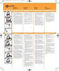
5-Step Installation Guide<br />
STEP 1. Mount the <strong>FenceMaster</strong><br />
The <strong>FenceMaster</strong> is easy to install. Mount the <strong>FenceMaster</strong> on a<br />
wall, under cover, out of reach of children, adjacent to a power<br />
outlet. Install where there is no risk of the <strong>Energizer</strong> incurring<br />
fire or mechanical damage.<br />
Using the 2 screws provided,<br />
screw the wall mount to the<br />
wall. Attach the <strong>FenceMaster</strong><br />
to the wall mount by hooking<br />
the <strong>FenceMaster</strong> over the 2<br />
prongs and snapping the<br />
bottom into place.<br />
To remove: use slotted screwdriver to<br />
release the bottom clip and lift the<br />
<strong>FenceMaster</strong> off the wall mount.<br />
STEP 2. Install the earth system.<br />
The most effective place for a earth system is in continuously<br />
damp soil (see figure (a) overleaf). For dry areas with poor<br />
earthing conditions, install the fence using figure (b) overleaf.<br />
Install the earth system at least 33ft from any power supply<br />
earth peg, underground telephone or power cable. Drive one<br />
6ft earth stake into the ground, until only 5cm (2”)<br />
remain above the ground.<br />
Using double insulated cable (046099), remove 2” of<br />
plastic coating from one end of the cable wire. Press the green<br />
(EARTH) terminal button and insert the wire into the terminal.<br />
Lay out the cable down walls and out to the earth stake. Attach<br />
the cable to the earth stake by removing 10cm (4”) of insulation<br />
from the cable at the earth stake, then clamp the exposed wire<br />
to the stake using an earth clamp. Tighten the clamp.<br />
Note: Poor grounding can cause interference on telephone<br />
lines, radios and televisions. This can be recognised by a clicking<br />
sound on telephones.<br />
<strong>FenceMaster</strong> Kit:<br />
Wall<br />
mount<br />
a) Using double insulated cable (046099), remove 2” of plastic<br />
coating from one end of the cable wire. Press the green (EARTH)<br />
terminal button and insert the wire into the terminal.<br />
Lay out the cable down walls and out to the earth stake. Attach the<br />
cable to the earth stake by removing 10cm (4”) of insulation from the<br />
cable at the earth stake, then clamp the exposed wire to the stake using<br />
an earth clamp. Tighten the clamp.<br />
b) Using the 6m (18ft) wire provided, uncoil the wire to its full length and<br />
push another earth stake into the ground. Connect the end of the wire<br />
to the earth stake as (a) above.<br />
c) Push the third earth stake into the ground mid-way between the first<br />
two and connect to the wire as above.
ALL HOT WIRE SYSTEM for areas with good earthing conditions.<br />
GREEN<br />
GREEN<br />
Earth Stake<br />
Earth Stake<br />
STEP 3. Install the fence<br />
RED<br />
RED<br />
The animal must touch the wire and the<br />
ground to feel a shock.<br />
HOT<br />
HOT<br />
HOT<br />
Figure A<br />
EARTH RETURN SYSTEM for areas with poor earthing conditions.<br />
The animal must touch both a HOT wire<br />
and the earth wire to feel an effective<br />
shock.<br />
HOT<br />
EARTH<br />
HOT<br />
Figure B<br />
a. Plan the fence line. Avoid rough, stony or steep areas if<br />
possible. For maximum fence length use multi-wire (at least 3<br />
wires connected in parallel) fencing.<br />
b. Run out the bottom wire between the end posts.<br />
c. Tension wires until there is only a slight visible sag.<br />
d. Connect all live wires in parallel at the end of each fence<br />
section using joint clamps (010851/010868).<br />
e. Conduct the fence system under gateways, rather than<br />
overhead. Do not use electric gates to get power across<br />
gateways. Install double insulated cable (046099) in a<br />
plastic pipe (for physical protection), 30cm (12”) deep. Turn<br />
the ends of the pipe down to keep water out. Connect each<br />
end of the cable to the joint clamps (010851/010868).<br />
f. Use cut-out switches (060705) to allow sections of the fence<br />
system to be switched off during fence maintenance. Put a<br />
switch at each gateway and at every major change in fence<br />
direction.
g. When joining wires under tension, use a figure eight or reef<br />
knot.<br />
OFFSET FENCE<br />
Existing non-electric fences can be protected to last for many<br />
more years simply by attaching offset brackets (010974/010912)<br />
and an electrified wire on one or both sides of the non-electric<br />
fence. Use a single offset wire, positioned at two thirds the<br />
height of the animal (chest height) to be controlled.<br />
OPTIONS FOR WIRE AND POST SPACINGS<br />
These figures are guidelines only for flat country conditions.<br />
Note: Symbol indicates a live, pulse-carrying wire<br />
Symbol indicates an earth wire.<br />
Dairy Cows/Beef Cattle<br />
Post spacing 20-25m (60 - 75ft)<br />
750mm (30”)<br />
12345678901234567890<br />
12345678901234567890<br />
Dairy Cows/Beef Cattle<br />
Post spacing 20-25m (60 - 75ft)<br />
12345678901234567890<br />
250mm (10”)<br />
250mm (10”)<br />
12345678901234567890<br />
12345678901234567890<br />
12345678901234567890<br />
Dairy Cows/Beef Cattle<br />
Post spacing 20-30m (60 - 90ft)<br />
250mm (10”)<br />
250mm (10”)<br />
550mm (22”)<br />
12345678901234567890<br />
12345678901234567890<br />
12345678901234567890<br />
Horses<br />
Post spacing 20-30m (60 - 90ft)<br />
250mm (10”)<br />
250mm (10”)<br />
1200mm (48”)<br />
12345678901234567890<br />
12345678901234567890<br />
12345678901234567890<br />
250mm (10”)<br />
12345678901234567890<br />
12345678901234567890<br />
12345678901234567890<br />
12345678901234567890<br />
12345678901234567890<br />
12345678901234567890<br />
12345678901234567890<br />
12345678901234567890<br />
12345678901234567890
Rabbits/Garden pests<br />
Post spacing 6m (20ft)<br />
125mm (5”)<br />
90mm (3½”)<br />
90mm (3½”)<br />
12345678901234567890<br />
115mm (4½”)<br />
12345678901234567890<br />
12345678901234567890<br />
Domestic Dogs<br />
Post spacing 6m (20ft)<br />
150mm (6”)<br />
175mm (7”)<br />
175mm (7”)<br />
12345678901234567890<br />
115 (4½”)<br />
12345678901234567890<br />
12345678901234567890<br />
STEP 4: Connect the fence<br />
Connect the <strong>Energizer</strong>’s red (FENCE)<br />
terminal to the fence using double<br />
insulated cable (046099).<br />
Remove 2” of plastic coating from<br />
one end of the cable. Press the green<br />
(EARTH) terminal button and insert<br />
the wire into the terminal.<br />
Attach the other end of the cable to<br />
the fence using a joint clamp (010851).<br />
<strong>FenceMaster</strong> Kit:<br />
STEP 5. Plug the <strong>FenceMaster</strong> into a power outlet.<br />
Check that the light on the front of<br />
the <strong>FenceMaster</strong> is flashing.<br />
12345678901234567890<br />
12345678901234567890<br />
12345678901234567890<br />
12345678901234567890<br />
12345678901234567890<br />
12345678901234567890<br />
GREEN<br />
To ground<br />
system<br />
RED<br />
To fence<br />
Connect the <strong>Energizer</strong>’s red (FENCE) terminal to the fence using the<br />
double insulated cable (046099) provided. Remove 2” of plastic<br />
coating from one end of the cable. Press the green (EARTH) terminal<br />
button and insert the wire into the terminal. Attach the other end of the<br />
cable to the fence using the joint clamp (010851) provided.<br />
Light
VOLTAGE CHECK LIST<br />
Yes<br />
Unplug the <strong>Energizer</strong> from<br />
the power supply and<br />
remove the fence wire from<br />
the red (FENCE) terminal.<br />
Plug <strong>Energizer</strong> in again and<br />
check, using a DVM3 Digital<br />
Volt Meter (075037). Is the<br />
voltage across the terminals<br />
greater than 5000 volts?<br />
Yes<br />
Test the earth<br />
system using<br />
the DVM3.<br />
Is the ground<br />
voltage more<br />
than<br />
200 volts?<br />
Yes<br />
Improve the earth<br />
system: add<br />
galvanised earth<br />
stakes to the earth<br />
system until the earth<br />
voltage is<br />
200 volts or below.<br />
Is the <strong>Energizer</strong> operating?<br />
<strong>Energizer</strong> needs<br />
to be serviced.<br />
No<br />
No<br />
No<br />
Test the<br />
power supply.<br />
If the power<br />
supply is OK<br />
then the<br />
<strong>Energizer</strong><br />
needs to be<br />
serviced.<br />
1. Check the electrical connections<br />
are secure eg. from the fence to<br />
the red (FENCE) terminal, from<br />
the ground system to the green<br />
(GROUND) terminal, at gates etc.<br />
2. Check the voltage on the fence<br />
every 33m (100ft) using the<br />
DVM3. Note if the voltage is<br />
dropping. The closer to a fault,<br />
the lower the voltage reading<br />
will be.<br />
Become aware of things that<br />
cause faults and always be on the<br />
lookout for: stray pieces of wire<br />
on the fence, heavy undergrowth,<br />
cracked or broken<br />
insulators, broken wires etc.
Materials and Tools<br />
For fence specifications and design contact your <strong>Gallagher</strong><br />
dealer.<br />
<strong>Gallagher</strong> dealers offer a complete range of products for your<br />
Power Fence.<br />
Permanent Fence<br />
<strong>FenceMaster</strong><br />
<strong>Energizer</strong><br />
GROUND FENCE
Portable Fence
Service of double-insulated Appliances<br />
In a double-insulated controller, two systems of insulation are<br />
provided instead of grounding. No equipment grounding<br />
means is provided in the supply cord of a double insulated<br />
controller, nor should a means for equipment grounding be<br />
added to the controller. Servicing a double insulated controller<br />
requires extreme care and knowledge of the system, and<br />
should be done only by qualified service personnel.<br />
Replacement parts for a double insulated controller must be<br />
identical to the parts they replace. A double-insulated<br />
controller is marked with the words “DOUBLE INSULATION” or<br />
“DOUBLE INSULATED”. The symbol for double insulation<br />
may also be marked on the appliance. To reduce the risk of<br />
electric shock, this fence controller has a polarised plug (one<br />
blade is wider than the other). This plug will fit in a polarised<br />
outlet only one way. If the plug does not fit fully in the outlet,<br />
reverse the plug. If it still does not fit, contact a qualified<br />
electrician to install the proper outlet. Do not change the plug<br />
in any way.<br />
Save these instructions<br />
<strong>FenceMaster</strong> complies with international safety regulations.<br />
<strong>Gallagher</strong> reserves the right to make changes without notice to any product<br />
specification to improve reliability, function or design. E & OE.