Installation 1. Preparations 2. Connecting pipes 3. Connecting fittings
Installation 1. Preparations 2. Connecting pipes 3. Connecting fittings
Installation 1. Preparations 2. Connecting pipes 3. Connecting fittings

You also want an ePaper? Increase the reach of your titles
YUMPU automatically turns print PDFs into web optimized ePapers that Google loves.
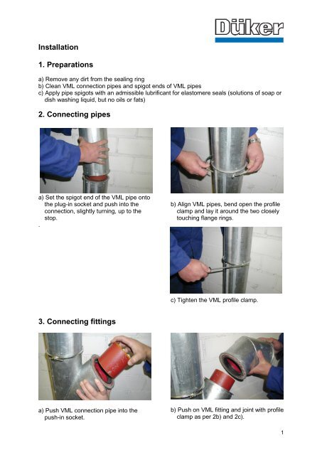
<strong>Installation</strong><br />
<strong>1.</strong> <strong>Preparations</strong><br />
a) Remove any dirt from the sealing ring<br />
b) Clean VML connection <strong>pipes</strong> and spigot ends of VML <strong>pipes</strong><br />
c) Apply pipe spigots with an admissible lubrificant for elastomere seals (solutions of soap or<br />
dish washing liquid, but no oils or fats)<br />
<strong>2.</strong> <strong>Connecting</strong> <strong>pipes</strong><br />
a) Set the spigot end of the VML pipe onto<br />
the plug-in socket and push into the<br />
connection, slightly turning, up to the<br />
stop.<br />
.<br />
<strong>3.</strong> <strong>Connecting</strong> <strong>fittings</strong><br />
a) Push VML connection pipe into the<br />
push-in socket.<br />
b) Align VML <strong>pipes</strong>, bend open the profile<br />
clamp and lay it around the two closely<br />
touching flange rings.<br />
c) Tighten the VML profile clamp.<br />
b) Push on VML fitting and joint with profile<br />
clamp as per 2b) and 2c).<br />
1
4. Shortening pipe lengths<br />
VML <strong>pipes</strong> are delivered in standard lengths of 3m. The required pipe lengths can be<br />
obtained on site with a pipe cutting machine or a belt saw. The first step is to cut the VML<br />
pipe to the exact length and to remove the insulation from the spigot.<br />
a) Mark cutting positions<br />
Cut I: measure of complete required<br />
pipe length<br />
Cut II: length of insulation removal<br />
as follows:<br />
DN 50 74 mm<br />
DN 80 77mm<br />
DN 100 86 mm<br />
DN 125 95 mm<br />
DN 150 95 mm<br />
DN 200 100 mm<br />
b) Cut pipe at the required length (cut I)<br />
c) Cut steel plate cover and insulation (cut<br />
II). Maximum cutting depth 10 mm!!<br />
d) Remove steel plate cover and<br />
insulation.<br />
2
5. Inserting flange rings on cut <strong>pipes</strong><br />
a) Clean the VML pipe spigot.<br />
b) Push in VML flange ring with HD-<br />
Duromer hard foam insert between<br />
interior and exterior pipe.<br />
c) Beat in the VML flange ring uniformly<br />
using a wooden board and align it in 90°<br />
angle to the pipe axis.<br />
The spigot end of the pipe must have<br />
the following dimensions:<br />
DN 50 29 mm<br />
DN 70 32 mm<br />
DN 100 41 mm<br />
DN 125 50 mm<br />
DN 150 50 mm<br />
DN 200 55 mm<br />
d) Fix VML flange ring with self-cutting<br />
screws Ø 4 mm, max. length 10 mm .<br />
DN 50 and 70 min. 4 screws<br />
DN 100 up to 150 min. 6 screws<br />
DN 200 min. 8 screws<br />
3
6. Fixing of VML pipelines<br />
Basic rules:<br />
- Fixings are to be placed in regular<br />
intervals between the connections, the<br />
distance before and after each profile<br />
clamp being no more than 0.25 m.<br />
- For pipe lengths up to 0.75 m, one fixing<br />
in the middle of the pipe is sufficient.<br />
7. VML <strong>pipes</strong> with accompanying heating<br />
If drainage pipe installations are to be<br />
protected from frost and the resulting<br />
damages, e.g. in unheated stock buildings,<br />
parking lots etc., an electrical pipe heating<br />
is required.<br />
VML <strong>pipes</strong> with accompanying heating are<br />
delivered in the nominal dimensions<br />
DN 50 up to DN 200 in lengths of 1000,<br />
2000 and 3000 mm, each pipe length with<br />
a connection cable of <strong>1.</strong>0 m.<br />
VML pipe lengths of less than 1000 mm as<br />
well as VML <strong>fittings</strong> normally do not<br />
require a heating, as the medium does not<br />
change its temperature significantly on<br />
these short lengths.<br />
Only in the following cases the VML<br />
pipeline including short pipe lengths and<br />
<strong>fittings</strong> must receive an accompanying<br />
heating in order to avoid frost damages:<br />
- VML pipelines with ongoing base or<br />
collection lines that are subject to frost<br />
- VML draft <strong>pipes</strong> above the frost-safe<br />
depth at the connection to the base line<br />
- VML pipelines with free outlet of the drain<br />
water pipeline<br />
VML <strong>pipes</strong> to length below 1m and <strong>fittings</strong><br />
with accompanying heating are available<br />
as special versions.<br />
- Horizontal pipelines must be fixed<br />
sufficiently at all changes of direction and<br />
branches. Pipelines fixed on pendulum<br />
clamps must be secured against any<br />
movement every 10 or 15 m with special<br />
fixed points.<br />
- Down <strong>pipes</strong> are to be fixed in a maximum<br />
interval of <strong>2.</strong>5 m. Every pipe length is to<br />
be fixed no more than <strong>2.</strong>5 m below and<br />
above the profile clamp.<br />
The pipe lengths or <strong>fittings</strong> with<br />
accompanying heating are connected to<br />
the on-site electric cable that must be laid<br />
parallel to the pipeline. Pipe lengths of less<br />
than 1000 mm length are to be cut out of<br />
VML <strong>pipes</strong> without heating according to<br />
the instructions. VML <strong>pipes</strong> with heating<br />
cannot be cut.<br />
4
Technical data of the accompanying<br />
heating:<br />
- connection tension 220 V / 50 Hz<br />
- heating performance at 0°C: 19,5 W/m<br />
heating band<br />
- electrical connection: 1,0 m for each pipe<br />
length<br />
connection cable: Y SL - IZ - 3 x 1,5 mm²<br />
- max. temperature of medium: 65°C<br />
- conductor in the heating band: tin-coated<br />
copper conductor<br />
1 x 1,2 mm² / 1,9 mm²<br />
- min. bending radius of the heating band:<br />
10 mm<br />
Advantages of the self-limiting heating<br />
band:<br />
- The performance of the heating band is<br />
always proportional to the overall length,<br />
i.e. 19,5 W/m at 0°C (e.g. length = 10m =<br />
overall performance 195 W). The system<br />
length can vary between a minimal VML<br />
pipe length with accompanying heating<br />
(1 m) up to the maximum heatable pipe<br />
length of 165 m, with a corresponding<br />
electric fuse protection.<br />
- The self-limiting effect avoids<br />
overheating or burn-through of the<br />
heating band<br />
- The self-limiting effect guarantees an<br />
economical frost protection, as the<br />
warmth generation is always adequate.<br />
In cold areas it uses more, in protected<br />
areas less energy.<br />
The complete electrical installation<br />
including the control panel must be carried<br />
out by a specialist for electrical<br />
installations. The VDE-regulations and any<br />
other applicable local rules are to be<br />
observed.<br />
Particularities:<br />
- Each heating element is to be connected<br />
with 230 V.<br />
- If a thermostat is installed with heating<br />
bands of more than 60 m, special<br />
precautions are necessary.<br />
5