laying instructions - Düker GmbH & Co KGaA
laying instructions - Düker GmbH & Co KGaA
laying instructions - Düker GmbH & Co KGaA

Create successful ePaper yourself
Turn your PDF publications into a flip-book with our unique Google optimized e-Paper software.
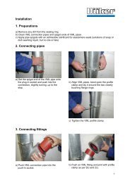
<strong>laying</strong> device v 300 d Marking of the installed<br />
thrust resisting joint<br />
Alternate moving of<br />
levers draws the spigot<br />
into the socket<br />
Locking<br />
attention: After connecting both parts, the locking of the segments is<br />
to be accomplished by moving the levers in the opposite direction.<br />
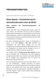
The exact positioning of the Tyton sit ® / tYtOn sit PlUs ® ring has to<br />
be checked by means of a suitable gauge on the whole circumference.<br />
Gauge<br />
note: Deviation of the installed thrust resisting joint is possible<br />
up to 3°.<br />
A pipe with 6 m length and 1° deflection deviates by approximately<br />
10 cm off the neutral axis.<br />
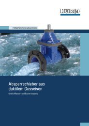
tyton sit ® tYtOn sit PlUs ®<br />
For permanent marking, we supply profiled rubber with blue<br />
(Tyton sit ® ) and accordingly white (tYtOn sit PlUs ® ) stripes.<br />
Fixing of these marking rings should be in accordance with the<br />
illustration.<br />
dismantling of<br />
thrust resisting joints<br />
Marking ring<br />
Dismantling plate<br />
• Push the spigot completely into the socket (relieving the steel segments)<br />
by using the <strong>laying</strong> device.<br />
• Lubricate dismantling blades on both sides and drive them into the<br />
socket gap around the whole circumference with a hammering device.<br />
• Dismount the joint with a dismounting clamp or the <strong>laying</strong> device.<br />
• Should it be impossible to insert the blades properly on whole<br />
circumference, the pipeline has to be cut.<br />
6 7