You also want an ePaper? Increase the reach of your titles
YUMPU automatically turns print PDFs into web optimized ePapers that Google loves.
Reference Pre-Amplifier<br />
<strong>User's</strong> <strong>Manual</strong><br />
1
Contents<br />
1 Preface......................................................................5<br />
1.1 Included........................................................................................6<br />
1.2 Transport.....................................................................................6<br />
2 Overview front panel................................................7<br />
3 Overview back panel................................................8<br />
4 Installation and power supply.................................9<br />
4.1 Placement.....................................................................................9<br />
4.2 Mains connection.........................................................................9<br />
4.3 Orientation of mains plug.........................................................10<br />
4.4 Additional earth connection.....................................................10<br />
5 Inputs and outputs.................................................11<br />
5.1 Inputs..........................................................................................11<br />
5.2 Outputs.......................................................................................11<br />
5.3 Recording devices......................................................................12<br />
5.4 <strong>Audionet</strong> Link............................................................................12<br />
6 Usage.......................................................................13<br />
6.1 Powering up...............................................................................13<br />
6.2 Switching on and off.................................................................13<br />
6.3 Mains phase detection...............................................................14<br />
6.4 Using <strong>Audionet</strong> Link.................................................................14<br />
6.5 Control elements on the front panel........................................15<br />
6.6 Volume control..........................................................................15<br />
6.7 Display........................................................................................16<br />
6.8 Input selection...........................................................................17<br />
6.9 Muting........................................................................................17<br />
7 Setup Menu.............................................................19<br />
7.1 Set Dim Level.............................................................................20<br />
7.2 Balance Adjust...........................................................................21<br />
7.3 Offset Adjust..............................................................................22<br />
7.4 Set DC Servo..............................................................................23<br />
3
7.5 Channel name............................................................................24<br />
7.6 Set Autostart..............................................................................24<br />
7.7 Set Off-Text................................................................................25<br />
7.8 Set Channel for By-Pass Mode.................................................26<br />
7.9 Overview factory defaults.........................................................26<br />
8 <strong>Audionet</strong> System Remote Control.........................27<br />
8.1 Key assignment PRE G2...........................................................29<br />
8.2 Screen 1......................................................................................30<br />
8.3 Screen 2......................................................................................31<br />
8.4 Screen 3......................................................................................32<br />
9 Special function By-Pass Mode.............................33<br />
10 Technical information.............................................35<br />
10.1 Design.........................................................................................35<br />
10.2 Power supply..............................................................................35<br />
10.3 Circuitry.....................................................................................35<br />
10.4 Handling.....................................................................................35<br />
10.5 Update PRE to PRE G2............................................................36<br />
11 Security advice........................................................37<br />
12 Technical data.........................................................38<br />
4
1 Preface<br />
The <strong>Audionet</strong> Team congratulates you on your purchase of this unit.<br />
Music lovers know about the importance of the pre amplifier: The pre<br />
amplifier determines the sound quality. For those enthusiast we developed<br />
the PRE G2, our pre amplifier reference.<br />
The PRE G2 is a luxurious source of pure sound. With the highest accuracy<br />
and resolution, coarse and fine dynamic precision and overwhelming<br />
spatiality it reproduces music in all its naturalness.<br />
The PRE G2 does not accept compromise. With fundamental scientific<br />
research and elaborate development and trial, each detail was conceived<br />
and tested. The circuitry is state-of-the-art, its design beyond all doubt<br />
and all its components painstakingly selected.<br />
As nothing else could satisfy our demands, we produce operational amplifiers,<br />
incremental encoder and signal cables ourselves. Volume is controlled<br />
by an electronically switched and in real-time linearized resistor<br />
network made of discrete high quality metal film resistors. The audio<br />
signal path and control circuitry are decoupled optically. Input and output<br />
circuits are immune to negative influences of connected devices. Thus,<br />
the PRE G2 manifests the limits of what is possible nowadays regarding<br />
measuring techniques. Noise, distortion and crosstalk are almost eliminated.<br />
A microprocessor facilitates versatile control functionality and highest<br />
handling comfort. All information is delivered through a big vacuum<br />
fluorescent display. Every function is supported by the remote control.<br />
Never show the PRE G2 to other pre amplifiers! The will go green with<br />
envy.<br />
But before you start listening to your new <strong>Audionet</strong> PRE G2, please read<br />
this manual carefully so you are able to use and enjoy all functions of this<br />
unit without drawback on music quality.<br />
5
1.1 Included<br />
Included you will find the following items:<br />
• the reference pre amplifier PRE G2<br />
• the <strong>Audionet</strong> System Remote Control Harmony One<br />
• the user's manual (that you are currently reading)<br />
• one standard power cord<br />
• one green-yellow cord for an additional earth connection<br />
1.2 Transport<br />
Important<br />
• Please transport the PRE G2 only in the included package.<br />
• Always use the plastic bag to prevent scratches on the casing.<br />
• Please allow the PRE G2 to adapt to the climatic conditions in your<br />
listening room before you switch on the unit for the first time after<br />
transport.<br />
6
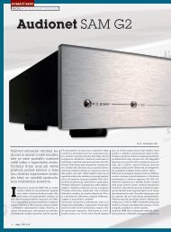
2 Overview front panel<br />
volume<br />
PRE G2<br />
Stereo Preamplifier mute set input power<br />
7<br />
volume knob<br />
(incremental<br />
encoder)<br />
IR remote<br />
control recevier<br />
power<br />
key<br />
input<br />
key<br />
set<br />
key<br />
mute<br />
key<br />
Display
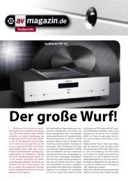
3 Overview back panel<br />
6 5 4 3 2 1 14 12 6 5 4 3 2 1<br />
gnd<br />
phase<br />
AC: 220/240 V<br />
50/60 Hz<br />
8<br />
7 8 9 10<br />
11 13 15 7 8<br />
9 10<br />
9 Inverted Cinch (line) output, left/right<br />
10 Monitor output, left/right<br />
1 Balanced (XLR) input no. 1, left/right<br />
2 Cinch (line) input no. 2, left/right<br />
11 Outputs <strong>Audionet</strong> Link 1 and 2<br />
12 Mains input<br />
3 Cinch (line) input no. 3, left/right<br />
4 Cinch (line) input no. 4, left/right<br />
13 Marking mains phase<br />
14 Mains switch<br />
15 Additional earth connector<br />
5 Cinch (line) input no. 5, left/right<br />
6 Cinch (line) input no. 6, left/right<br />
7 Cinch (line) output, left/right<br />
8 Balanced (XLR) outputs, left/right
4 Installation and power supply<br />
Important<br />
• During connecting and removing of sources or amplifiers to the<br />
PRE G2 all units of your audio system have to be switched off to<br />
prevent damage of the PRE G2 or any of the other connected<br />
units.<br />
• Please make sure that all cables are in absolute best conditions!<br />
Broken shields or short-cut cables could damage the PRE G2<br />
and/or any other connected unit.<br />
4.1 Placement<br />
Important<br />
• It is recommended to place the PRE G2 into a high quality rack or<br />
onto a stable table.<br />
• Do not expose the unit to direct sunlight.<br />
• Do not place the PRE G2 in close range to heat sources like radiators.<br />
• Do not place the PRE G2 on top of other units, especially not on top<br />
of power amplifiers, pre amplifiers or similar that produce heat. Both<br />
units could suffer damage from thermal overload.<br />
• Do not use the unit in places where it is exposed to vibrations.<br />
• Do not place the unit close to loudspeakers or into the corner of a<br />
room where it is exposed to high levels of sonic energy, which might<br />
reduce the sound quality of the unit.<br />
4.2 Mains connection<br />
The mains input 12 * is on the back panel of the PRE G2. To connect the<br />
unit to mains use the included mains cord. If you prefer to use a different<br />
power cord make sure that it meets the specifications for your home country.<br />
Important<br />
• The electrical specifications of your home country must meet the<br />
electrical specifications printed onto the back panel.<br />
* see numbers in section 'Overview back panel' on page 8.<br />
9
• The PRE G2 is a Class I unit and must be earthed. Please ensure a<br />
stable earth connection. Phase ('hot' pin) is marked on the back panel<br />
('phase') 13 .<br />
• If you connect the mains cord please make sure that mains switch<br />
14 at the back panel is switched off.<br />
• Never pull the mains plug while the PRE G2 is switched on! Before you<br />
pull the mains cord off its socket 12 at the back panel, power down the<br />
unit to stand-by mode and switch off the unit using mains switch 14 .<br />
Only in cases of extended absence (like vacations) or if massive trouble<br />
on the mains power is to be expected you should switch off the PRE G2<br />
from the mains using mains switch 14 . To disconnect the unit completely<br />
from mains pull the mains plug.<br />
Tip<br />
• The use of high quality mains cords could improve sound quality.<br />
Ask your local dealer for more information.<br />
4.3 Orientation of mains plug<br />
The correct polarization of mains is important for reasons of audio clarity<br />
and stability. Please connect the mains cord so that the hot pin of the wall<br />
outlet is connected to the pin of the mains input 12 marked 'PHASE'<br />
13 . Your <strong>Audionet</strong> PRE G2 is able to detect a wrong polarization of the<br />
mains plug during start-up. If the message<br />
Attention: Mains<br />
Phase incorrect!<br />
appears in the display, switch off the unit and flip the mains plug in the<br />
wall outlet (see section 'Mains phase detection' on page 14).<br />
4.4 Additional earth connection<br />
Included with the PRE G2 you will find a green-yellow cord for the additional<br />
earth connection. Attach this cord to the earth connector 15 on the<br />
back panel of the PRE G2 and put the plug into the mains socket right<br />
beside the mains cord of your PRE G2. This ensures an additional and<br />
stable earth connection resulting in a better sound.<br />
Note<br />
• We strongly recommend using the additional earth connection!<br />
• Also, a stable earth connection is necessary for the PRE G2 detecting<br />
the polarization of mains phase correctly.<br />
10
5 Inputs and outputs<br />
Important<br />
• During connecting and removing of sources or amplifiers to the<br />
PRE G2 all units of your audio system have to be switched off to<br />
prevent damage of the PRE G2 or any of the other connected<br />
units.<br />
• Please make sure that all cables are in absolute best conditions!<br />
Broken shields or short-cut cables could damage the PRE G2<br />
and/or any other connected unit.<br />
5.1 Inputs<br />
The PRE G2 is equipped with one balanced (XLR) 1 and 5 Cinch (line)<br />
inputs 2 to 6 for connecting signal sources at line level. Due to its<br />
double mono design, left and right channel input jacks are separated on<br />
the back panel.<br />
Please connect the left and right input of the same number printed on the<br />
back panel of the PRE G2 to the corresponding output of the source you<br />
would like to connect to the PRE G2.<br />
5.2 Outputs<br />
The PRE G2 is equipped with a pair of balanced (XLR) 8 and a pair of<br />
Cinch (line) outputs 7 and 9 for the left and right channel each to connect<br />
the unit to your amplifier(s). The Cinch (line) output 9 is inverted.<br />
Due to the double mono design the left and right output jacks are separated.<br />
Use the left and right Cinch (line) output 7 to connect the PRE G2 to<br />
your power amplifier(s) using high quality Cinch cables. Alternatively,<br />
you may connect the power amplifier using the balanced (XLR) outputs<br />
8 in case your power amplifier does not support Cinch (line) inputs.<br />
The inverted outputs 9 are primarily designated for amplifiers in<br />
bridged operations (in combination with the Cinch (line) outputs 7 ).<br />
Important<br />
• Bridged operations of an amplifier demand a correct setup and connection.<br />
Please consult your dealer and/or the manufacturer of your<br />
power amplifier to prevent damage to your equipment.<br />
11
Tip<br />
• Of course, you may use the inverted outputs 9 to connect your<br />
PRE G2 to an additional amplifier. In this case, please mind to<br />
change polarization of the speaker connection at your amplifier<br />
(change + to – and – to +).<br />
• Altogether, you can connect up to four stereo or up to eight mono<br />
power amplifiers to the PRE G2 simultaneously utilising all outputs.<br />
5.3 Recording devices<br />
To prevent any negative influence on the audio signal, the PRE G2 has no<br />
regular (tape) monitor loop.<br />
For recording purposes, please connect your recording system like DAT<br />
or tape-deck to the monitor output 10 of your PRE G2. Use only input<br />
no. 6 6 of the PRE G2 to playback your recording system. On selecting<br />
input no. 6 6 the monitor output 10 is switched off to prevent any<br />
feedback loops between the PRE G2 and your recording system.<br />
Please use inputs no. 1 1 to no. 5 5 to connect sources you like to record.<br />
With these inputs the monitor output 10 will always be active.<br />
5.4 <strong>Audionet</strong> Link<br />
For your convenience, the PRE G2 can switch on/off all other <strong>Audionet</strong><br />
units (e.g. power amplifiers) connected via '<strong>Audionet</strong> Link' by a simple<br />
touch on the included remote control or the power key on the front panel.<br />
You only need a simple optical 'Toslink' cable. Connect the '<strong>Audionet</strong><br />
Link' output 11 of your PRE G2 to the '<strong>Audionet</strong> Link' input of unit to<br />
be controlled.<br />
The PRE G2 is equipped with two identical '<strong>Audionet</strong> Link' outputs. In<br />
case you would like to control more than one <strong>Audionet</strong> unit via '<strong>Audionet</strong><br />
Link', use the second '<strong>Audionet</strong> Link' output 11 of your PRE G2 as well.<br />
Tip<br />
• <strong>Audionet</strong> source units and power amplifiers are usually equipped not<br />
only with an '<strong>Audionet</strong> Link' input, but additionally with an '<strong>Audionet</strong><br />
Link' output to connect further <strong>Audionet</strong> devices to be controlled via<br />
'<strong>Audionet</strong> Link' in a daisy chain. Connect this '<strong>Audionet</strong> Link' output<br />
to the '<strong>Audionet</strong> Link' input of the next <strong>Audionet</strong> unit using a simple<br />
optical 'Toslink' cable allowing you to switch on/off your complete<br />
<strong>Audionet</strong> system by your <strong>Audionet</strong> pre amplifier.<br />
12
6 Usage<br />
All functions of the PRE G2 are microprocessor controlled. This guarantees<br />
highest precision, exclusive functions, easy handling and protection<br />
against operating error.<br />
6.1 Powering up<br />
First of all, please make sure your PRE G2 is connected correctly to your<br />
signal sources, power amplifier(s) and mains (see section 'Installation<br />
and power supply' on page 9 and 'Inputs and outputs' on page 11). The<br />
PRE G2 is a stand-by unit. Please operate the mains switch 12 on the<br />
back panel. The display shows for a brief moment a welcome message.<br />
After that the PRE G2 is in stand-by mode. The display will indicate the<br />
stand-by mode with either the text off or with a small dot (pixel) in the<br />
display (see section 'Set Off-Text' on page 25).<br />
Only in cases of extended absence (like vacations) or if massive trouble<br />
on the mains power is to be expected it is recommended to disconnect the<br />
PRE G2 from mains. Operate the mains switch 14 on the back panel of<br />
the unit to switch off the unit from mains. The display will go dark.<br />
Important<br />
• Before you switch off the PRE G2 from mains, power down and<br />
discharge completely all units connected to the outputs of the<br />
PRE G2.<br />
6.2 Switching on and off<br />
To power up the PRE G2 from stand-by mode, press the power key on<br />
the front panel. The PRE G2 issues the message Waking up.... In case<br />
the mains plug has the incorrect polarization a warning will appear in the<br />
display (see section 'Mains phase detection' on page 14). After that the<br />
unit is in normal operating mode.<br />
If you would like to switch off the unit, please press the power key on the<br />
front panel. First, the display shows the message Going to sleep..<br />
which then will be replaced by the stand-by text (see section 'Set Off-Text'<br />
on page 25). The unit is now in stand-by mode.<br />
Note<br />
• Of course, you may switch on/off the PRE G2 with the included<br />
<strong>Audionet</strong> System Remote Control Harmony One. For detailed information<br />
please refer to section 'Screen 3' on page 32.<br />
13
6.3 Mains phase detection<br />
The correct polarization of mains is important for reasons of audio clarity<br />
and stability. Please connect the mains cord that the 'hot' pin of the wall<br />
outlet is connected to the pin marked 'PHASE' 13 of the mains input 12<br />
on the back panel. The PRE G2 recognizes the incorrect polarization of<br />
the mains plug automatically. Right after switching on the unit from<br />
stand-by mode by pressing the power key on the front panel the following<br />
message will appear in the display in case the mains polarization is<br />
incorrect:<br />
Attention: Mains<br />
Phase incorrect!<br />
If you read the above message, switch off the unit by pressing the power<br />
key. Please wait until the display no longer reads Going to sleep...<br />
Disconnect the PRE G2 by operating the mains switch 14 . Now pull the<br />
mains plug and re-insert it into the mains socket rotated by 180°.<br />
If you switch on the unit again, the warning should not appear now.<br />
Important<br />
• If the PRE G2 issues the mains polarization warning or no warning at<br />
all for both positions of the mains plug, check the connection to earth<br />
of your mains socket and mains cord. You have to ensure a stable<br />
connection to earth for the mains phase detection of the PRE G2<br />
to work correctly!<br />
6.4 Using <strong>Audionet</strong> Link<br />
Your PRE G2 is equipped with two '<strong>Audionet</strong> Link' outputs 11 allowing<br />
you to switch on/off further <strong>Audionet</strong> units (e.g. power amplifiers, CD<br />
player or tuner) connected via '<strong>Audionet</strong> Link' (see also section '<strong>Audionet</strong><br />
Link' page 12).<br />
If the rest of your <strong>Audionet</strong> system is connected to your PRE G2 via<br />
'<strong>Audionet</strong> Link', all linked units will be automatically switched on/off as<br />
soon as you switch on/off the PRE G2 using the power key on the front<br />
panel or the remote control.<br />
Note<br />
• The 'switch on/off' signal is issued to both '<strong>Audionet</strong> Link' outputs of<br />
the PRE G2 simultaneously. Thus, both outputs are identical in their<br />
function and may be used either in combination or separately.<br />
• Please read section '<strong>Audionet</strong> Link' on page 12. Also, consult the<br />
user's manuals of your <strong>Audionet</strong> components connected via '<strong>Audionet</strong><br />
Link' for further information.<br />
14
6.5 Control elements on the front panel<br />
The front panel has four keys to control your PRE G2 (see section<br />
'Overview front panel' on page 7). With these keys you can control all<br />
functions as well as all setup options to adjust the unit to your preferences<br />
(see section 'Setup Menu' on page 19).<br />
mute Use this key to mute or de-mute the PRE G2 (see section<br />
'Muting' on page 17).<br />
set Push key shortly to navigate through the setup menu. Keep<br />
key pushed for longer than two seconds to exit the setup<br />
menu (see section 'Setup Menu' on page 19).<br />
input Push key to enter input selection (see section 'Input selection'<br />
on page 17).<br />
power Use key to switch on/off the unit (see section 'Switching on<br />
and off' on page 13).<br />
6.6 Volume control<br />
Use the volume knob on the front panel of the PRE G2 to set the desired<br />
volume level.<br />
Turn volume knob clockwise to increase volume, turn counter clockwise<br />
to decrease volume.<br />
The volume control of the PRE G2 runs in a range from –80 dB to<br />
+10 dB in real 1 dB steps relatively to the level of the input signal. Differences<br />
in input levels can be adjusted for each input channel of the<br />
PRE G2 separately (see section 'Offset Adjust' on page 22).<br />
The volume knob is a magnetically buffered incremental impulse encoder<br />
without end stop.<br />
Note<br />
• The volume knob is also used to select an option from the setup menu<br />
items (see section 'Offset Adjust' on page 22) as well as to select the<br />
input channel (see section 'Input selection' on page 17).<br />
• To control the volume with the <strong>Audionet</strong> System Remote Control<br />
Harmony One use keys Vol+ und Vol- (see section 'Key assignment<br />
PRE G2' on page 29).<br />
15
6.7 Display<br />
The display provides in the normal operating mode the following information:<br />
5 INPUT FIVE<br />
LEVEL –46+0dB<br />
1 number of the currently selected input channel, corresponds to the<br />
number printed above the input jack on the back panel (see section<br />
'Overview back panel' on page 8)<br />
2 name of the currently selected input channel, fully user-definable<br />
(see section 'Channel name' on page 24)<br />
3 current volume level in dB relative to the input level (see section<br />
'Volume control' on page 15).<br />
4 offset for input level of currently selected input channel (see section<br />
'Offset Adjust' on page 22).<br />
As soon as you enter the setup menu by pushing the set key, the display<br />
changes to show information related to the selected menu item. For further<br />
display details refer to the description of each menu item in section<br />
'Setup Menu' starting from page 19.<br />
Note<br />
1<br />
2<br />
• After 10 minutes without any user interaction the 'display saver' is<br />
invoked automatically. The display then shows only the number of<br />
the currently selected input channel and the current volume level.<br />
Please refer to section 'Set Dim Level' on page 20 for further information<br />
on the 'display saver' mode.<br />
16<br />
3<br />
4
6.8 Input selection<br />
Push the input key on the front panel, then select the desired input channel<br />
using the volume knob. The display shows:<br />
SELECT INPUT:<br />
5 INPUT FIVE<br />
The 2 nd line of the display provides the number and the (user-definable)<br />
name of the currently selected input channel.<br />
The PRE G2 features a 'soft' input selection. During the switching of<br />
inputs, first the volume is stepped down to –80 dB, followed by switching<br />
off the outputs. Now the input section switches to the new input channel.<br />
Afterwards the outputs are switched on again, and finally the volume is<br />
stepped up to its original level.<br />
Note<br />
• Leave the input selection function by pressing the input key again.<br />
• Using the <strong>Audionet</strong> System Remote Control Harmony One, select an<br />
input channel by simply pressing the corresponding key (see section<br />
'Screen 1' on page 30) or digit key (see section 'Key assignment<br />
PRE G2' on page 29). Alternatively, use the keys Ch+ and Ch- to<br />
switch to the next or previous input channel without using the Select<br />
Input function (see section 'Key assignment PRE G2' on page<br />
29).<br />
6.9 Muting<br />
Push the mute key on the front panel to mute or un-mute the PRE G2.<br />
Just as well as the input selection, the PRE G2 uses 'soft' muting, i.e. volume<br />
is stepped down gently to –80 dB, then the outputs are switched off.<br />
The 2 nd line of the display informs the user of a muted unit with the text<br />
MUTE. The text is displayed even if the dim level is set to Off.<br />
To de-mute the PRE G2 press the mute key again. Here as well, the volume<br />
is stepped up gently to its original level after switching on the outputs.<br />
17
Note<br />
• While the unit is muted, you may of course select a different input<br />
channel as described above. But the PRE G2 will stay muted until you<br />
push the mute key again to de-mute the unit.<br />
• If you turn the volume knob, while the unit is muted, the new volume<br />
level will be set and the unit de-muted, if you turn the volume knob<br />
clockwise, i.e. you turn up the volume.<br />
• Use key on the <strong>Audionet</strong> System Remote Control Harmony One to<br />
control the muting of your PRE G2 from the comfort of your listening<br />
chair (see section 'Key assignment PRE G2' on page 29).<br />
18
7 Setup Menu<br />
To adjust the PRE G2 to your preferences, please use the setup menu.<br />
Push the set key shortly on the front panel to get to the first item of the<br />
setup menu. Navigate to the next menu item by pushing the set key<br />
shortly. Below you will find a list of all menu items of the setup menu.<br />
After last menu item pushing the set key leaves the setup menu automatically.<br />
Of course, you may leave the setup menu from each menu item by pushing<br />
and holding the set key for longer than two seconds. The PRE G2<br />
will return to normal operation mode.<br />
The order of items in the setup menu is:<br />
*1<br />
SET DIM LEVEL<br />
<br />
BALANCE ADJ.<br />
<br />
OFFSET ADJUST<br />
<br />
SET DC SERVO<br />
<br />
channel name<br />
<br />
SET AUTOSTART<br />
<br />
SET OFF-TEXT<br />
<br />
SET CHANNEL FOR BY-PASS MODE<br />
Change any setting of a menu item using the volume knob on the front<br />
panel.<br />
Tip<br />
• All settings of the setup menu can be dealt with by using the keys of<br />
the front panel. However, if you prefer to change settings from the<br />
comfort of your listening chair, please use the included remote control.<br />
For more information about the remote control and its usage<br />
please refer to section '<strong>Audionet</strong> System Remote Control' on page 27.<br />
*1 = push set key shortly (less than two seconds)<br />
19
Note<br />
• If you make no adjustments for longer than 12 seconds the PRE G2<br />
will automatically leave the setup menu and return to normal operations<br />
mode.<br />
• While you are in the setup menu the display brightness is set to 100%<br />
for better readability. After leaving the setup menu the display<br />
brightness is automatically reset to is user selected level.<br />
• If you power down the PRE G2 to stand-by mode all settings are<br />
stored automatically in the non-volatile memory of the unit. Even after<br />
disconnecting from mains the PRE G2 will still remember your<br />
settings.<br />
In the following all options of the setup menu are explained in detail.<br />
7.1 Set Dim Level<br />
To adjust the brightness of the display on the front of the PRE G2 press<br />
the set key once for less than two seconds.<br />
Now use the volume knob to select the desired brightness. Turn clockwise<br />
to increase or turn counter clockwise to decrease the brightness.<br />
Important<br />
• Long-term usage of the display set to maximum brightness (setting<br />
100%) may cause extended signs of wear resulting in a decay<br />
of contrast or brightness of individual dots in the display. Do not<br />
use the display with a brightness set higher than the factory default<br />
of 50% over a longer period of time!<br />
Note<br />
SET DIM LEVEL:<br />
██████______ 50%<br />
current brightness setting<br />
• Is the brightness set to Off the display is only on during setup or<br />
volume adjustments. It switches off automatically several seconds after<br />
the last user entry.<br />
20
• The PRE G2 activates the 'display saver' automatically after 10 minutes<br />
without any user entry.<br />
• During active 'display saver', the display shows only the number of<br />
the selected input channel and current volume level in the form of<br />
In 4 -47dB. The display brightness is always reduced to 25%, and<br />
the location of the information text will change randomly every 12<br />
seconds to prevent any 'burn-in' effect of the display.<br />
• The 'display saver' is de-activated and the display returns to its normal<br />
mode as soon as any user entry is detected.<br />
• The user cannot switch off the automatic 'display saver' function!<br />
Tip<br />
• Get to the option Set Dim Level at anytime using the key<br />
Dim Display on screen page 2 of the included <strong>Audionet</strong> System<br />
Remote Control Harmony One. Use keys Vol+ and Vol- to select<br />
desired brightness.<br />
7.2 Balance Adjust<br />
Push set key twice for less than two seconds. The display reads now:<br />
BALANCE ADJ.: +0<br />
--<br />
Adjust now the balance by using the volume knob.<br />
Turn clockwise to shift the balance to the right. The 1 st line of the display<br />
shows the volume difference in dB between left and right channel. A<br />
positive value means that the balance is shifted to the right.<br />
Turn the volume knob counter clockwise to shift the balance to the left.<br />
The value in the display is now negative.<br />
The PRE G2 allows the user to shift the balance up to 9 dB to the left or<br />
the right.<br />
The 2 nd line of the display visualises a balance shift with one or more<br />
symbols. The orientation of the symbol represents the direction of the<br />
balance shift, the number of symbols equals the amount of 1 dB steps the<br />
balance was shifted.<br />
21<br />
current balance setting in dB
Example:<br />
►►► balance shifted to the right by 3 dB<br />
◄◄◄◄◄ balance shifted to the left by 5 dB<br />
– – no balance shift<br />
Note<br />
• In normal display mode the PRE G2 indicates a balance shift by the<br />
corresponding symbol in the 2 nd line of the display. Thus you are able<br />
to see at any time if the balance was shifted:<br />
5 INPUT FIVE<br />
► LEVEL –46+0dB<br />
► = balance shifted to the right<br />
◄ = balance shifted to the left<br />
• A balance shift is carried out internally by attenuating the corresponding<br />
channel, i.e. if the balance is shifted to the right, the level of<br />
the left channel is attenuated and vice versa.<br />
7.3 Offset Adjust<br />
Push set key on the front panel three times for less than two seconds to<br />
get to the offset adjustment option.<br />
Turn volume knob clockwise to increase the input level of the current<br />
channel. If you would like to decrease the input level, turn volume knob<br />
counter clockwise. The display informs you of your selection:<br />
5 INPUT FIVE<br />
LEVEL –46+3dB<br />
level adjustment in dB<br />
For each of the six input channels of the PRE G2 you can define the adjustment<br />
of the input level in the range of –9 dB to +9 dB in steps of 1 dB<br />
to match the different output levels of sources connected to the PRE G2.<br />
22
Tip<br />
• If you would like to adjust the input level offset for just another input<br />
channel, please use the keys Ch+ and Ch- of the <strong>Audionet</strong> System<br />
Remote Control to switch to the desired channel. The PRE G2<br />
does not leave the setup menu, and you are able to adjust the offset<br />
for each input channel very easily.<br />
7.4 Set DC Servo<br />
Push the set key four times for less than 2 seconds to adjust the DC Servo<br />
option.<br />
Turn volume knob on the front panel clockwise to activate the DC Servo<br />
for the currently selected input channel. Turn volume knob counter<br />
clockwise to disable the DC Servo.<br />
SET DC SERVO:<br />
In 3 : disabled<br />
current selected input channel status DC Servo<br />
disabled The DC Servo is disabled for the currently selected input<br />
channel.<br />
active The DC Servo is active for the currently selected input<br />
channel.<br />
Activate the DC Servo if the source connected to the PRE G2 holds a<br />
high DC component in its output signal. The DC Servo eliminates the DC<br />
component. The currently selected input channel is now AC-coupled.<br />
Usually the DC Servo may be disabled.<br />
Note<br />
• In normal operating mode the display indicates an active DC Servo<br />
for the currently selected input channel by a symbol right beside the<br />
channel name in the 1 st display line. Thus you can see at any time if<br />
the DC Servo is active:<br />
DC Servo is active<br />
5 INPUT FIVE *<br />
LEVEL –46+0dB<br />
23
Tip<br />
• If you would like to set the DC Servo option for more than just the<br />
current input channel, please use keys Ch+ and Ch- of the <strong>Audionet</strong><br />
System Remote Control to select the desired input channel. The<br />
PRE G2 does not leave the setup menu, and you are able to adjust the<br />
DC Servo option for each input channel very easily.<br />
7.5 Channel name<br />
You can assign a fully user-definable name up to 12 characters in length<br />
to each of the six input channels. Push the set key on the front panel five<br />
times. The display will then show the number of the currently selected<br />
input channel and the assigned channel name. The cursor in the 2 nd line of<br />
the display marks the character you now may alter.<br />
Turn the volume knob to select the desired character. Push the mute key<br />
to advance the cursor to the next character position. After last position the<br />
cursor wraps around and starts at the first position again.<br />
4 CD PLAYER<br />
▲<br />
currently selected input channel cursor assigned channel name<br />
Tip<br />
• If you would like to re-name the channel name for more than just the<br />
currently selected input channel, use keys Ch+ and Ch- of the<br />
<strong>Audionet</strong> System Remote Control to switch to the desired input<br />
channel. The PRE G2 does not leave the setup menu, and you are<br />
able to define the channel name for other input channels very easily.<br />
Press key of the <strong>Audionet</strong> System Remote Control to advance the<br />
cursor one position to the right.<br />
7.6 Set Autostart<br />
Push the set key six times for less than two seconds to get to the<br />
Autostart option.<br />
Turn the volume knob on the front panel clockwise to activate the<br />
Autostart function. Turn the volume knob counter clockwise to disable<br />
the Autostart function.<br />
24
SET AUTOSTART:<br />
active<br />
disabled The Autostart function is disabled. If you switch on the<br />
unit with the mains switch 14 on the back panel the<br />
PRE G2 will go into stand-by mode. You have to push<br />
the power key on the front panel or, alternatively, the<br />
keys Power On or Power Toggle of the <strong>Audionet</strong><br />
System Remote Control to start up the unit to go into<br />
normal operating mode *) .<br />
active The Autostart function is active. As soon as you switch<br />
on the unit with the mains switch 14 on the back panel<br />
the PRE G2 will start up and automatically go into normal<br />
operating mode. Use this setting for timer controlled<br />
operations.<br />
7.7 Set Off-Text<br />
Push the set key on the front panel seven times for less than two seconds<br />
to select the display option during stand-by mode.<br />
Turn the volume knob clockwise to select display option 'dot'. Turn volume<br />
knob counter clockwise to select display option 'off'.<br />
SET OFF-TEXT:<br />
dot<br />
off The stand-by mode is indicated by the text off.<br />
dot The stand-by mode is indicated by a small dot (pixel) in<br />
the display.<br />
Note<br />
• Approx. every 12 seconds the stand-by mode indicator changes position<br />
randomly in the display to prevent any 'burn in' effect (see section<br />
'Set Dim Level' on page 20).<br />
*) or use a corresponding Activity; see separate user's manual to the <strong>Audionet</strong> Sytem Remote Control<br />
Harmony One<br />
25
7.8 Set Channel for By-Pass Mode<br />
Push the set key on the front panel eight times for less than two seconds<br />
to enter the option for selecting the input channel in By-Pass Mode.<br />
Use the volume knob on the front panel to select the input channel you<br />
would like to use for the By-Pass Mode.<br />
Note<br />
SET CHANNEL FOR<br />
BY-PASS MODE: 3<br />
dot<br />
• For detailed information about the By-Pass Mode please refer to section<br />
'Special function By-Pass Mode' on page 33.<br />
• If no input channel is selected for the By-Pass Mode, the display will<br />
show: SET CHANNEL FOR BY-PASS MODE: - -.<br />
Important<br />
• Before you can use the By-Pass Mode you have to select the input<br />
channel that is used for the By-Pass Mode. Otherwise the PRE G2<br />
will issue the warning: No input for By-Pass selected.<br />
• For safety reasons the factory default settings have no input channel<br />
selected for By-Pass Mode (display: SET CHANNEL FOR BY-<br />
PASS MODE: - -).<br />
7.9 Overview factory defaults<br />
Option Setting<br />
SET DIM LEVEL 50%<br />
BALANCE ADJ. - -<br />
OFFSET ADJUST 0 dB (for all inputs)<br />
SET DC SERVO<br />
Channel name<br />
26<br />
In 1-5: disabled<br />
In 6: active<br />
1: BALANCED<br />
2: INPUT TWO<br />
3: INPUT THREE<br />
4: INPUT FOUR<br />
5: INPUT FIVE<br />
6: TAPE INPUT<br />
SET AUTOSTART disabled<br />
SET OFF-TEXT dot<br />
SET CHANNEL FOR BY-PASS MODE - -
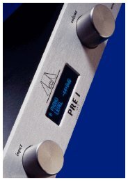
8 <strong>Audionet</strong> System Remote Control<br />
Every function of the PRE G2 is accessible via the <strong>Audionet</strong> Systemfernbedienung<br />
Harmony One. Additionally, up to 14 other devices can be<br />
controlled by the Harmony One.<br />
Press key Devices to enter Device Mode. The display now lists all<br />
devices included in the current configuration of the Harmony One. Select<br />
PRE G2 from the list to set the Harmony One to controlling the<br />
PRE G2. The Device Mode gives you access to all the possible commands<br />
to control your PRE G2. The following explains all these commands<br />
in detail.<br />
Important<br />
• During everyday use, you should never need to use the Device Mode<br />
of your Harmony One, but control the PRE G2 (and other devices of<br />
your audio setup) by customizing your Activities. For detailed information<br />
on how to customize and use Activities on your Harmony<br />
One please consult the separate user's manual that came with your<br />
Harmony One.<br />
1<br />
5<br />
My Activities:<br />
1/2 pages<br />
Listen to CDs<br />
Watch a DVD<br />
1 Power key for use with Activities, turns all devices off that are included<br />
into the current Activity. See separate user's manual of Harmony<br />
One.<br />
2 Depending on the operational mode, the touch screen of the Harmony<br />
One shows a list of Activities or Devices, help or infrared<br />
commands and any available listings.<br />
3 If a menu or listing stretches over more than one screen page, use the<br />
corresponding arrow buttons to go to the next or previous page of the<br />
menu or listing. (see also separate user's manual of the Harmony<br />
One).<br />
4 Devices key, lists all the devices on the display, and allows you to<br />
select and directly control any device included in the configuration of<br />
27<br />
Mi 14:51<br />
3 3<br />
Options<br />
CD with VIPG3<br />
Devices<br />
2<br />
4
the remote control (see separate user's manual of Harmony One). Select<br />
PRE G2 to enter Device Mode for controlling the PRE G2.<br />
5 Activities key: Press this key to view a list of Activities you have<br />
added. Press the button next to the Activity you want to select, and<br />
the Harmony One will control your entertainment system (see separate<br />
user's manual of Harmony One).<br />
Important<br />
• The Power key is only available for Activities. In Device<br />
Mode the Power key has no function.<br />
• Even without using an Activity, the user is able to control all<br />
functions of the PRE G2 using the Harmony One in Device Mode.<br />
• The keys described below to control the PRE G2 refer to the factory<br />
default programming of the <strong>Audionet</strong> System Remote<br />
Control Harmony One. Understandably, any changes done to this<br />
setup by the user cannot be discussed here.<br />
Tip<br />
• In order to switch the PRE G2 on/off, without using an Activity,<br />
please use the keys Power On , Power Off and/or<br />
Power Toggle on screen 3 (see section 'Screen 3' on page 32). Of<br />
course, it is possible to control the PRE G2 without any Activity, but<br />
to tap the full potential of the Harmony One you need to configure<br />
Activities customized to your needs (please refer to separate manual<br />
of the remote control Harmony One).<br />
Note<br />
• Please read the separate user's manual to your <strong>Audionet</strong> system remote<br />
control Harmony One. Activities, Devices and Device Mode as<br />
well as customizing the remote control are discussed there.<br />
28
8.1 Key assignment PRE G2<br />
1<br />
2<br />
4<br />
6<br />
PRE G2:<br />
1/3 pages<br />
Balanced<br />
Input<br />
Current<br />
Activity<br />
1 Use key Menu to navigate through the setup menus. This key has<br />
the same function as key set on the front panel (see section 'Setup<br />
Menu' on page 19) or key Set on screen page 2 (see section 'Screen<br />
2' in page 31).<br />
2 Vol+ , increases the volume of the PRE G2, also for selecting setup<br />
options. Vol+ equals turning the volume knob on the front panel<br />
clockwise.<br />
3 Ch+ , switches to the next input channel (see section 'Input selection'<br />
on page 17).<br />
29<br />
Mi 14:51<br />
Input Three Input Four<br />
Tape Input<br />
Input Two<br />
Phono Input<br />
Devices<br />
3<br />
5<br />
7
4 Vol- , decreases the volume of the PRE G2, also for selecting setup<br />
options. Vol- equals turning the volume knob on the front panel<br />
counter clockwise.<br />
5 Ch- , switches to the previous input channel (see section 'Input selection'<br />
on page 17).<br />
6 , mutes the PRE G2. This key has the same function as the key<br />
mute o the front panel (see section 'Muting' on page 17).<br />
7 Digit keys for direct input selection (see section 'Input selection' on<br />
page 17).<br />
8.2 Screen 1<br />
1<br />
PRE G2:<br />
1/3 pages<br />
Balanced<br />
Input<br />
Current<br />
Activity<br />
1 Directly selects input channel no. 1.<br />
2 Directly selects input channel no. 2.<br />
3 Directly selects input channel no. 3.<br />
4 Directly selects input channel no. 4.<br />
5 Directly selects input channel no. 5.<br />
6 Directly selects input channel no. 6.<br />
30<br />
Input Two<br />
Devices<br />
Mi 14:51<br />
3 Input Three Input Four 4<br />
5<br />
Input Five Tape Input 6<br />
2
8.3 Screen 2<br />
1<br />
2<br />
PRE G2:<br />
2/3 pages<br />
By-Pass<br />
Mode<br />
Dim Display<br />
Current<br />
Activity<br />
1 By-Pass Mode switches on/off the By-Pass Mode of the PRE G2.<br />
Please read section 'Special function By-Pass Mode' on page 33<br />
first, before you use the special function By-Pass Mode.<br />
2 Dim Display jumps directly to the setup menu item Set Dim<br />
Level (see section 'Set Dim Level' on page 20).<br />
3 Use Set to navigate through the setup menus. This key has the<br />
same function as the set key on the front panel (see section 'Setup<br />
Menu' on page 19) or key Menu of the Harmony One (see section<br />
'Key assignment PRE G2' on page 29).<br />
31<br />
Devices<br />
Mi 14:51<br />
Set 3
8.4 Screen 3<br />
2<br />
PRE G2:<br />
3/3 pages<br />
Power<br />
Toggle<br />
Current<br />
Activity<br />
1 If the PRE G2 is in stand-by mode, press key Power On to switch<br />
the unit on.<br />
2 Use Power Toggle to switch on/off the PRE G2. This key has the<br />
same function as the power key onthe front panel. If the PRE G2 is<br />
in stand-by mode, Power Toggle switches on the unit. If the<br />
PRE G2 is already switched on, Power Toggle switches off the<br />
unit to stand-by mode.<br />
3 If the PRE G2 is witched on, use key Power Off to switch the unit<br />
off to stand-by mode.<br />
32<br />
Power On<br />
Devices<br />
Mi 14:51<br />
1<br />
Power Off 3
9 Special function By-Pass Mode<br />
Tip<br />
• The By-Pass Mode was primarily intended to integrate its overwhelming<br />
sound quality of the PRE G2 into an existing home cinema<br />
setup or to expand an existing excellent stereophonic system based on<br />
the PRE G2 to a complete home cinema setup without missing out on<br />
the qualities of the PRE G2. To realise this kind of setup, please proceed<br />
as follows:<br />
1. Connect your home cinema pre amplifier according to its user's<br />
manual.<br />
2. Connect the output for the front channels Left and Right not to<br />
the power amplifier but to one of the free inputs of the PRE G2.<br />
3. Now connect the outputs of the PRE G2 to the corresponding<br />
power amplifier for the channels Left and Right.<br />
4. Use menu item 'Set Channel for By-Pass Mode' of the setup menu of<br />
the PRE G2 to select the input channel for By-Pass Mode you<br />
connected the outputs Left and Right of the home cinema pre<br />
amplifier to.<br />
5. Connect now all high quality 2-channel analog sources to the remaining<br />
inputs of the PRE G2.<br />
6. Connect your DVD player to your home cinema pre amplifier as<br />
usual.<br />
Use the PRE G2 to listen to high quality analog sources. If you would<br />
like to use your home cinema system activate the By-Pass Mode of<br />
the PRE G2 and use your home cinema pre amplifier as usual.<br />
Important<br />
• Please read the complete section about the special function By-<br />
Pass Mode first before you use this function in order to prevent<br />
maloperations and possible damage to your audio system and/or<br />
hearing.<br />
• By factory default no input channel is selected for the By-Pass<br />
Mode. Use menu option 'Set channel for By-Pass Mode' to select<br />
desired input channel for the By-Pass Mode. If no input channel<br />
is selecteds and you try to invoke the By-Pass Mode the PRE G2<br />
will issue the warnung: No input for By-Pass selected<br />
(see section'Set Channel for By-Pass Mode' on page 26).<br />
Is the By-Pass Mode active the volume control of the PRE G2 is bypassed.<br />
The PRE G2 passes through the input signal to the outputs with<br />
its full level.<br />
33
Please use setup option 'Set Channel for By-Pass Mode' to select which of the<br />
six input channels of the PRE G2 is fed through to the outputs if By-Pass<br />
Mode is active.<br />
Important<br />
• First, select the input channel used for By-Pass Mode (see section 'Set<br />
Channel for By-Pass Mode' on page 26), before you activate the By-Pass<br />
Mode for the first time.<br />
Activate the special function By-Pass Mode of your PRE G2 by pressing<br />
the key By-Pass Mode of the <strong>Audionet</strong> System Remote Control. The<br />
signal at the input channel selected for By-Pass Mode operations is<br />
passed through the PRE G2 at a level of 0 dB (i.e. no change in volume<br />
level) to the outputs.<br />
Important<br />
• Please check the correct connection and setup before you use the<br />
By-Pass Mode for the first time. The input signal will be passed<br />
through to the outputs at full level!<br />
As soon as the By-Pass Mode is activated, the PRE G2 will ignore all<br />
control commands coming from the keys on the front panel or remote<br />
control (exceptions see below)!<br />
Important<br />
There are only two possibilities to disable the By-Pass Mode:<br />
1. Press key By-Pass Mode of the <strong>Audionet</strong> System Remote Control.<br />
The PRE G2 switches back to the input channel selected before<br />
resetting the volume to its prior level.<br />
2. Push the power key on the front panel. The PRE G2 switches off to<br />
stand-by mode.<br />
Note<br />
• If you leave the By-Pass Mode by pushing the power key on the<br />
front panel, this mode will not be saved, i.e. if you switch on the<br />
PRE G2 again, the unit will switch to the last saved input channel selection<br />
and not to the By-Pass Mode. If you would like to use the By-<br />
Pass Mode again, press key By-Pass Mode of the <strong>Audionet</strong> System<br />
Remote Control Harmony One.<br />
34
10 Technical information<br />
10.1 Design<br />
The PRE G2 has complete double mono design for absolute channel<br />
separation. To optimize the high frequency properties the circuitry was<br />
consequently miniaturized and SMD technology implemented. Signal<br />
path ways are limited to their minimum, and chassis and circuit design<br />
magnetically and capacitively optimized. The System is controlled and<br />
monitored by a powerful microprocessor. The control unit and the analog<br />
section are galvanically separated by opto-couplers.<br />
10.2 Power supply<br />
Power is provided by two encapsulated 100 VA toroid core transformers.<br />
Fast buffer capacitors, especially designed for <strong>Audionet</strong>, with 82.000 µF<br />
for each channel and extremely fast, discrete regulators stabilize the supply<br />
voltages. Additionally, voltages are smoothed locally by 12 regulators<br />
for each channel. Thus, the power supply is quasi de-coupled from mains<br />
accumulator-like. Also, the digital section has its separate power supply.<br />
10.3 Circuitry<br />
All operational amplifiers (OP) in the signal path are discrete and optimized<br />
for their special purpose. Each OP is supplied with power by to<br />
fast and discrete regulators. All 10 discrete OP modules work in low distortion<br />
Class A mode and have a gain-bandwidth product of 1.5 GHz.<br />
The input OPs have a nearly infinite input impedance and constant capacity.<br />
Thus, they do not load the signal source. Gold plated precision relays<br />
switch both signal and ground of the inputs.<br />
The output OPs work in high bias current Class A mode rendering them<br />
immune against reflux of the power amplifiers.<br />
Volume and balance is controlled, free of electro-mechanical components,<br />
by an electronically switched and in real-time linearized precision<br />
resistor network with true 1 dB resolution.<br />
10.4 Handling<br />
A microprocessor controls and monitors all functions. A two line, 16digit<br />
display informs the user about all operating modes and makes it<br />
easy to adjust the PRE G2 to the user's preferences. The unit also features<br />
35
user-definable channel names and input level adjustment for each channel.<br />
Two '<strong>Audionet</strong> Link' outputs facilitate easy daisy-chaining of <strong>Audionet</strong><br />
devices for remote switching on/off via '<strong>Audionet</strong> Link'. Each input<br />
channel features a user selectable DC Servo to eliminate DC components<br />
on source signals.<br />
10.5 Update PRE to PRE G2<br />
Note<br />
• An <strong>Audionet</strong> PRE updated to does not feature a DC Servo. The corresponding<br />
menu item in the setup menu is omitted for these units.<br />
Quality of performance and appearance is the equal to the original<br />
PRE G2.<br />
36
11 Security advice<br />
Important<br />
• Avoid packaging material, especially plastic bags, coming into children's<br />
hands!<br />
• Store and operate the unit in a dry room at a reasonable room temperature<br />
only!<br />
• Avoid moisture, any liquids, dirt or small objects getting into the<br />
unit!<br />
• Set up the unit in a sufficiently ventilated environment!<br />
• Do not cover the unit!<br />
• Do not open the unit. Unauthorised opening will void warranty!<br />
• Do not short-circuit the outputs!<br />
• During connecting or removing the PRE G2 to/from sources and/or<br />
power amplifiers all units have to be switched off to prevent damage<br />
of the PRE G2 or any of the other connected units.<br />
• Use dry cloth for cleaning!<br />
We would like to wish you many exciting listening experiences with your<br />
new <strong>Audionet</strong> product.<br />
If you still have any questions, do not hesitate to ask your competent<br />
<strong>Audionet</strong> dealer or contact us directly.<br />
37
12 Technical data<br />
Function microprocessor controlled pre-amplifier<br />
Frequency response<br />
THD+N<br />
0 – 2,000,000 Hz (-3 dB), DC coupled<br />
2 – 2,000,000 Hz (-3 dB), AC coupled<br />
>102 dB @ 20 kHz<br />
>114 dB @ 1 kHz<br />
SNR > 110 dB, 2 VRMS input<br />
Channel separation >140 dB, 20 – 20,000 Hz<br />
Inputs<br />
Outputs<br />
Output impedance 22 Ohms real<br />
Output current max. 60 mA<br />
5 pair Cinch line, gold plated<br />
1 pair XLR balanced, gold plated<br />
Mains 230 V, 50…60 Hz<br />
Power consumption max. 50 Watts<br />
Dimensions<br />
Weight 20 kg<br />
Finish<br />
1 pair Cinch line, gold plated<br />
1 pair Cinch inverted, gold plated<br />
2 pair XLR balanced, gold plated<br />
1 pair Cinch Monitor, gold plated<br />
2 <strong>Audionet</strong> Link, optical<br />
1 connector, gold plated, for additional earth connection<br />
Width 430 mm<br />
Height 140 mm<br />
Depth 420 mm<br />
Front: brushed aluminium, black anodised, white print<br />
or aluminium 'nature', anodised, black print<br />
Display: red or blue<br />
Top cover: brushed aluminium, black anodised<br />
Chassis: steel, black coated<br />
38
Features<br />
Options<br />
- <strong>Audionet</strong> System Remote Control Harmony One<br />
(included)<br />
- automatic detection of main polarization<br />
- separate power supply for digital and analog sections<br />
- separate power supply for left and right audio channels<br />
(analog)<br />
- electronically switched and real time linearised<br />
precision resistors for volume control<br />
- discrete <strong>Audionet</strong> operational amplifiers in the<br />
audio signal path<br />
- audio and control functions optically decoupled<br />
- full DC coupling, no capacitors in the signal path<br />
- selectable AC coupling via DC servo<br />
- separate level adjustment for each input channel<br />
- By-Pass function (e.g. for integration into home cinema<br />
systems)<br />
- Auto start function for timer operations<br />
- <strong>Audionet</strong> Link outputs for remote control of other<br />
<strong>Audionet</strong> components (e.g. power amplifiers)<br />
recommended for phono applications:<br />
external phono pre-amplifier <strong>Audionet</strong> PAM<br />
(with optional external power supply <strong>Audionet</strong> EPS)<br />
Errors and omissions excepted. Specifications and design are subject to changes without prior notice.<br />
audionet is a trademark of Idektron GmbH & Co KG<br />
Engineered and produced by:<br />
Idektron GmbH & Co. KG, Herner Str. 299, Gebäude 6, 44809 Bochum, Germany<br />
www.audionet.de<br />
contact@audionet.de<br />
39