manual MAP1 en - Audionet
manual MAP1 en - Audionet
manual MAP1 en - Audionet

Create successful ePaper yourself
Turn your PDF publications into a flip-book with our unique Google optimized e-Paper software.
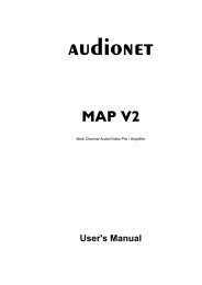
Multi Channel Audio/Video Pre - Amplifier<br />
User's Manual
Cont<strong>en</strong>ts<br />
Placem<strong>en</strong>t and connection 4<br />
Additional earth connection 5<br />
<strong>Audionet</strong> Link 5<br />
Polarisation of mains plug 5<br />
Connecting the external power supply EPS 5<br />
Audio/Video-Connections 7<br />
First Steps 9<br />
Usage front panel 11<br />
<strong>Audionet</strong> System Remote Control 13<br />
Setup 26<br />
M<strong>en</strong>u Channel Setup 28<br />
M<strong>en</strong>u Decoder Setup 30<br />
M<strong>en</strong>u Global Setup 33<br />
M<strong>en</strong>u Video Setup 34<br />
M<strong>en</strong>u Bass Manager 35<br />
M<strong>en</strong>u Delay Manager 37<br />
Display 38<br />
On Scre<strong>en</strong> Display (OSD) 42<br />
Progressive Scan Card 43<br />
Overview video outputs 49<br />
USB Audio 50<br />
Security advice 54<br />
3
Placem<strong>en</strong>t and connection<br />
Important:<br />
• Warning! Please read this <strong>manual</strong> prior to operating the MAP 1 in order to<br />
avoid damage on your valuable equipm<strong>en</strong>t.<br />
Also, please make sure all units of your audio/video system are switched off while<br />
connecting or disconnecting any cables to avoid damage of the input and/or output<br />
sections of your units.<br />
Please make sure that your <strong>Audionet</strong> MAP 1 is installed at a place that is suffici<strong>en</strong>tly<br />
v<strong>en</strong>tilated to allow the heat to leave.<br />
The mains input 17 *) is located at the back panel of the MAP 1. Please use the<br />
provided power cord to connect the MAP 1 to mains. If you want to use a differ<strong>en</strong>t<br />
power cord make sure that it meets the specifications for your home country.<br />
Important:<br />
• The electrical specifications at the back must meet the specifications of your<br />
home country.<br />
• The mains switch at the back panel has to be switched off before connecting the<br />
MAP 1 to mains. The MAP 1 is a Class I device and must be earthed. Please<br />
<strong>en</strong>sure a stable earth connection. 'Phase'/'Hot pin' is marked at the back panel<br />
(PHASE) 17 .<br />
The MAP 1 is a stand by device. Please use the mains switch 17 at the back panel to<br />
switch on the MAP 1. After a short time the display reads off or small dot to report<br />
that the unit is in stand by mode now (see chapter 'Setup', section 'Global Setup', m<strong>en</strong>u<br />
item 'Set Stand By Text').<br />
Only in case of ext<strong>en</strong>ded abs<strong>en</strong>ce (like vacations) or if massive trouble on mains power<br />
is to be expected you should disconnect the unit from the mains. Switch off the MAP 1<br />
with the mains switch at the back panel 17 . The display will go out.<br />
Important:<br />
• Before switching off the mains switch of the MAP 1, please make sure that all<br />
units connected to the outputs of the MAP 1 are switched off, too.<br />
• Long term usage of the display set to maximum brightness (setting 100%) may<br />
cause ext<strong>en</strong>ded signs of wear resulting in a decay of contrast or brightness of<br />
individual dots in the display. Do not use the display with a brightness set higher<br />
than the factory default setting of 50% over a longer period of time (refer to<br />
Chapter 'Remote Control', section 'Scre<strong>en</strong> page 5')!<br />
*) see numbers on page 'Overview of connections'<br />
4
Additional earth connection<br />
Optionally, there is a special cord available for an additional earth connection to be used<br />
with earth connector 1 . Use the screw of earth connector 1 to connect the additional<br />
ground cord to the MAP 1. Put the plug of the ground cord into a mains socket near<br />
your power cord. The sound will be improved.<br />
Tip:<br />
• We strongly recomm<strong>en</strong>d using the additional earth connection!<br />
<strong>Audionet</strong> Link<br />
In connection with other <strong>Audionet</strong> devices like AMP I, AMP II, AMP II MAX, AMP<br />
III, AMP IV, AMP VII etc. your MAP 1 is able to switch on/off the complete system.<br />
Please connect a Toslink plastic fibre cable from the <strong>Audionet</strong>-Link Output 8 at the<br />
back of the MAP 1 to the <strong>Audionet</strong>-Link inputs of other <strong>Audionet</strong> devices. For further<br />
instructions please read the user's <strong>manual</strong> of the other <strong>Audionet</strong> devices.<br />
Polarisation of mains plug<br />
The correct polarizing of mains is important for reasons of audio clarity and stability.<br />
Therefore the <strong>Audionet</strong> MAP 1 indicates a wrong polarisation of the mains lead. While<br />
powering up, the MAP 1 checks the mains polarisation. If you read<br />
► Att<strong>en</strong>tion: ◄<br />
► Mains Phase incorrect ◄<br />
switch off the MAP and th<strong>en</strong> flip the plug in your wall outlet.<br />
Connecting the external power supply EPS<br />
Use the provided special cord to connect the optionally available EPS to the EPS-Input<br />
2 at the back panel of the MAP 1. Connect both (!!) units (MAP 1 and EPS) with<br />
mains. Switch on first the MAP 1 th<strong>en</strong> the EPS with the mains switch at the back of the<br />
units. The MAP 1 is now in stand by mode. You can start up the MAP 1 by pressing the<br />
power key at the front panel, or the key Power On or Power Toggle on the<br />
remote control.<br />
To disconnect both units from the mains please make sure first, that the MAP 1 is<br />
switched off to stand by mode using the power key at the front panel or the key<br />
Power Off or Power Toggle on the remote control. Now you can disconnect the<br />
units from the mains by switching off first the MAP 1, th<strong>en</strong> the EPS using the mains<br />
switch at the back panel of the units.<br />
5
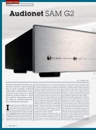
Overview of connections<br />
7<br />
Digital input 8<br />
USB-Audio<br />
8<br />
5<br />
4<br />
3<br />
2<br />
1<br />
6<br />
<strong>Audionet</strong> Link<br />
connector<br />
USB data interface<br />
Composite<br />
video output<br />
Composite<br />
video input<br />
DVI video<br />
input<br />
Connector for the external<br />
power supply EPS<br />
Additional earth<br />
connector<br />
AUDIONET<br />
USB<br />
USB<br />
IN 1 IN 2 FBAS<br />
(C B) (Y) (CR IN)<br />
LINK<br />
AUDIO<br />
CONTROL<br />
LBACK<br />
6<br />
RBACK<br />
2-Channel Analog<br />
inputs<br />
8-Channel<br />
analog input<br />
Multi-Channel<br />
analog output<br />
Digital inputs<br />
1 to 7<br />
Digital output:<br />
Digi Rec Select<br />
S-Video<br />
output<br />
S-Video<br />
inputs<br />
DVI video<br />
output<br />
Mains input and mains<br />
power switch<br />
10 9<br />
16 15 14 13 12 11<br />
Marking mains phase<br />
17
Audio/Video-Connections<br />
Analog Inputs:<br />
Connect 2-channel analog sources to one of the two analog inputs 9 (Analog In LEFT<br />
1/ RIGHT 1 or Analog In LEFT 2/ RIGHT 2). Both analog inputs are setup to pure<br />
analog 2-channel signal routing by default. If you have the 2-channel analog outputs of<br />
your DVD-Player, LaserDisc-Player, VCR or any other analog source connected to the<br />
MAP 1 and want to use Dolby * Pro Logic IIx or DTS ** Neo:6 for decoding Surround<br />
<strong>en</strong>coded stereo material, switch internal decoder mode to Multi-Channel for the<br />
corresponding analog input 9 (see chapter 'Setup', section 'Decoder Setup').<br />
If you have the optional phono card installed, plug in the MM- or MC pickup of your<br />
turn table into input Analog In LEFT 2/ RIGHT 2 9 and connect the chassis of the<br />
turn table to the ground screw GND 1 . The phono card offers indep<strong>en</strong>d<strong>en</strong>t selection of<br />
gain, input capacity and input resistance for optimal adjustm<strong>en</strong>ts to all kinds of<br />
available pickup systems. For further details please refer to the <strong>en</strong>closed user's <strong>manual</strong><br />
of the phono card.<br />
Digital Inputs (Digital Audio):<br />
Connect your digital sources to digital inputs 1 to 7 12 . By factory default digital<br />
inputs 1,2,3 and 5 are setup for multi channel decoding (Dolby Digital and DTS).<br />
Digital inputs 4,6,7 and 8 are setup for stereo PCM signals (all default setting can be<br />
changed by the user in the setup m<strong>en</strong>us!). Use digital input 8 7 to connect the MAP 1<br />
to a Computer using USB Audio to playback sound and music files (refer to chapter<br />
'USB Audio').<br />
In order to s<strong>en</strong>d DVD-Audio music data across the HighBit interface from the DVD<br />
player <strong>Audionet</strong> VIP 1) to the MAP 1, connect digital output 1 of the VIP with digital<br />
input Digital Audio IN 1 of the MAP 1. Furthermore, you need a second connection<br />
running from digital output 2 of the VIP to digital input Digital Audio IN 2 of the<br />
MAP 1. Only in case of both connections are setup and the switch for the interface<br />
mode on the back panel of the VIP is set to h-bit (refer to owner's <strong>manual</strong> of VIP), it is<br />
possible to receive and decode DVD-Audio data with the MAP 1.<br />
Note:<br />
• Data on the <strong>Audionet</strong> HighBit interface will be recognized and decoded<br />
automatically by the MAP 1. If the second data connection is missing the MAP 1<br />
will issue the error message: ► Check HighBit Cable 2 ◄.<br />
Please check the correct setup and connection of both cables from VIP to MAP 1.<br />
• Alternatively, you can use the digital input Digital Audio IN 3 of the<br />
MAP 1. Connect the datalink output of the VIP by using a common 'Firewire' or<br />
'IEEE1396' cable with the Digital Audio IN 3 of the MAP 1. In this case the switch<br />
for the interface mode on the back panel of the VIP has to be set to h-bit mode<br />
1 Make sure your VIP supports the HighBit DVD-Audio interface. Software upgrades are available for older models.<br />
7
(refer to owner's <strong>manual</strong> of VIP), to receive and decode DVD-Audio data with the<br />
MAP 1.<br />
External 8-Channel Analog Inputs:<br />
Plug in analog multi channel sources (external decoder, DVD-Player with internal<br />
decoder, SACD-Player etc.) into the 8-channel analog input 10 of the MAP 1.<br />
Note:<br />
• The External 8-Channel Analog Input provides no signal processing at all, only pure<br />
analog volume control!<br />
Analog Outputs:<br />
Pin assignm<strong>en</strong>t External 8-Channel Analog Input<br />
Pin Signal Pin Signal<br />
1 Front Left 14 Ground Front Left<br />
2 C<strong>en</strong>ter 15 Ground C<strong>en</strong>ter<br />
3 Front Right 16 Ground Front Right<br />
4 Subwoofer 17 Ground Subwoofer<br />
5 Left Surround 18 Ground Left Surround<br />
6 Right Surround 19 Ground Right Surround<br />
7 Left Back 20 Ground Left Back<br />
8 Right Back 21 Ground Right Back<br />
All analog outputs 11 are located in the section Analog Outputs in the right part of the<br />
back panel.<br />
Digital Outputs (Digital Audio Out):<br />
Select DigiRec Select in the setup m<strong>en</strong>u, which of the digital input 1 to 7 12 is<br />
routed to the digital output 13 . The digital record select works indep<strong>en</strong>d<strong>en</strong>tly,<br />
therefore you can use digital out for recording while list<strong>en</strong>ing to a differ<strong>en</strong>t source.<br />
Video Inputs (Video In / S-Video In):<br />
Plug in your cinch/composite video sources into video inputs IN 1 and IN 2 4 .<br />
S-Video sources are to be connected to video inputs S-Video In 1 and S-Video In 2 15 .<br />
Use the video inputs in any order as each of the 4 video inputs can be assigned to every<br />
audio input (see m<strong>en</strong>u 'Video Setup' and 'Channel Setup'). Ev<strong>en</strong> multiple assignm<strong>en</strong>ts<br />
8
are allowed, i.e. one and the same video input can be assigned to more than one audio<br />
input.<br />
Video Outputs:<br />
The video signal assigned to the curr<strong>en</strong>t audio input is available at the Video Out jacks;<br />
cinch video at FBAS 5 and S-Video at S-VIDEO 14 . All video signals at the cinch<br />
video inputs are converted to S-Video format by the internal 'Cinch Video to S-Video<br />
Converter' and available at the output S-VIDEO. The On Scre<strong>en</strong> Display (OSD) is<br />
available at video outputs VIDEO 5 and S-VIDEO 14 .<br />
Alternatively, both video inputs VIDEO IN1 and IN2 together with video output FBAS<br />
can be re-defined as secondary compon<strong>en</strong>t video (YUV) input (refer to chapter 'Setup'<br />
section 'Set video input' and chapter 'Progressive Scan Card' for further details and<br />
connection diagram).<br />
DVI Video In-/Outputs:<br />
The DVI video input and output sockets are both designed for analog and digital video<br />
signals (DVI-I). If no progressive scan card is installed, the analog or digital input<br />
signals of the DVI input socket are directly s<strong>en</strong>t to the output socket (refer to chapter<br />
'Setup' section 'Set video input' ).<br />
Note:<br />
• Digital DVI video signals are not processed by the installed progressive scan card<br />
but only routed through from input 3 to output 16 , if the option<br />
Set Video Input :<br />
DVI-Int. In<br />
is selected.<br />
• Interlaced analog video formats, which are fed into a video 4 , S-Video 15 or DVI<br />
analog input 3 can only be converted into a progressive digital DVI video format,<br />
if the optional progressive scan card and the optional DVI Module are both<br />
installed.<br />
• Please refer to chapter 'Progressive Scan Card' for detailed information about<br />
connection and configuration of the optional Progressive Scan Card.<br />
First Steps<br />
The following provides a short overview of the first steps and their order to setup the<br />
MAP 1. For any detailed description please refer to the sections 'Usage front panel' and<br />
'<strong>Audionet</strong> System Remote Control Harmony One'.<br />
After connecting your MAP 1 to the other compon<strong>en</strong>ts of your Hifi or Home Cinema<br />
system (refer to section 'Audio / Video connections'), some setup options have to be<br />
9
configured. Your MAP 1 needs information about the number of speakers, their<br />
distances from the list<strong>en</strong>ing position and s<strong>en</strong>sitivity to work with optimum performance.<br />
The setup procedure is quite easy if you stick to the following order:<br />
1. Number and size of speakers: Use key Bass Manager<br />
(refer to chapters ' <strong>Audionet</strong> System Remote Control Harmony One' and 'Setup')<br />
Select what kind of speakers you are using. Large refers to speakers that are<br />
capable of reproducing the complete bass domain down to the lowest frequ<strong>en</strong>cies.<br />
Use setting Small for bookshelf-type speakers or small sized design speakers that<br />
are not capable to produce a rich bass foundation due to their construction.<br />
According to these settings the MAP 1 determines automatically the amount of bass<br />
information that is s<strong>en</strong>t to each speaker. Due to the differ<strong>en</strong>t calculating operations<br />
that are needed for this bass managem<strong>en</strong>t, the perceived volume level may vary<br />
betwe<strong>en</strong> differ<strong>en</strong>t settings.<br />
2. Distance of speakers to the list<strong>en</strong>ing position: Use key Delay Manager<br />
(refer to chapters ' <strong>Audionet</strong> System Remote Control Harmony One' and 'Setup')<br />
Measure the distance of each speaker to your list<strong>en</strong>ing position and <strong>en</strong>ter the number<br />
into the Delay Manager. Your MAP 1 automatically calculates the necessary delay of<br />
each channel so that the music signals arrive at exactly the same time at your<br />
list<strong>en</strong>ing position. As the delay settings are calculated and setup in real time, the<br />
music signal may be influ<strong>en</strong>ced for the short mom<strong>en</strong>t of setting the new value.<br />
3. Level setup: Use key TestTone<br />
(refer to chapter ' <strong>Audionet</strong> System Remote Control Harmony One', section 'Scre<strong>en</strong><br />
page 6')<br />
The noise signal will support you to determine the correct level of each speaker, so<br />
all perceived volumes are the same. This setup is necessary as differ<strong>en</strong>t speakers<br />
have differ<strong>en</strong>t s<strong>en</strong>sitivities causing differ<strong>en</strong>t perceived volumes though the input<br />
signal has the same level.<br />
Note:<br />
• After adjusting the volume levels of all speaker channels we recomm<strong>en</strong>d to save<br />
these settings to all input channels as a simple start up for further channel or source<br />
dep<strong>en</strong>d<strong>en</strong>t level settings. To save the curr<strong>en</strong>t level settings to all input channels,<br />
press the following keys on the remote control:<br />
Save Setting Ch- <br />
Now all input channels have the same volume level settings. Of course, you can<br />
change these settings easily for each input channel indep<strong>en</strong>d<strong>en</strong>tly if necessary. After<br />
these 3 steps the most important global settings are done.<br />
Following the global setup there are lots of options that are valid for each input channel<br />
separately. These local settings are necessary to meet all the demands of differ<strong>en</strong>t<br />
source units connected to the inputs of the MAP 1 (please refer to section 'Setup',<br />
subsection 'Channel Setup' for further details).<br />
10
Usage front panel<br />
There are four keys at the front panel to control the MAP 1. Although most of the setup<br />
can be done using those keys, the included remote control provides much more comfort<br />
(refer to sections ' <strong>Audionet</strong> System Remote Control Harmony One' and 'Setup').<br />
The power key is used to switch on/off the MAP 1. To change volume or any settings<br />
in the setup m<strong>en</strong>us, please press the up and down keys. With the set key you skip<br />
through the m<strong>en</strong>u items of the setup m<strong>en</strong>us. If you press and hold the set key for more<br />
than two seconds, it will get you to the next setup m<strong>en</strong>u. For navigating through the<br />
m<strong>en</strong>us using the remote control, please refer to chapter ' <strong>Audionet</strong> System Remote<br />
Control Harmony One', section 'Navigate through a m<strong>en</strong>u'.<br />
Example: Navigating through m<strong>en</strong>us<br />
Level Setup<br />
Channel Setup<br />
key on remote control for<br />
direct access of m<strong>en</strong>u<br />
Adjust Channel Offset Left Front Front<br />
Adjust Channel Offset C<strong>en</strong>ter<br />
Adjust Channel Offset Right Front<br />
C<strong>en</strong>ter<br />
Adjust Channel Offset Right Surround Surround<br />
Adjust Channel Offset Right Back<br />
Adjust Channel Offset Left Back<br />
Adjust Channel Offset Left Surround<br />
Back<br />
Adjust Channel Offset Subwoofer Ch+ Subwoofer<br />
Adjust Channel Offset LFE Mix LFE<br />
Internal Decoder<br />
Set Video Input<br />
Channel Offset Adjust<br />
set (long)<br />
Set List<strong>en</strong>ing Mode List<strong>en</strong>ing Mode<br />
Set Digital Filter Digital Filter<br />
Set Dynamic Range<br />
Set Dual Mono<br />
Edit Channel Name<br />
Dynamic Range<br />
An overview of all m<strong>en</strong>us and their functions is provided on the next page. Please refer<br />
to example above as leg<strong>en</strong>d.<br />
Before describing all m<strong>en</strong>us and their m<strong>en</strong>u items, the functions of the remote control<br />
are explained in detail. Please use the remote control or, as alternative, the keys at the<br />
front panel to setup your MAP 1 according to your prefer<strong>en</strong>ces.<br />
11<br />
set (short)<br />
or Ch-<br />
Key on remote control for<br />
direct access of function
Overview of m<strong>en</strong>u structure<br />
RUN Mode<br />
Level Setup<br />
Channel Setup<br />
Decoder Setup<br />
Global Setup<br />
Video Setup<br />
Bass Manager<br />
Delay Manager<br />
Select Input<br />
Set List<strong>en</strong>ing Mode<br />
Adjust Channel Offset Left Front Front<br />
Adjust Channel Offset C<strong>en</strong>ter C<strong>en</strong>ter<br />
Adjust Channel Offset Right Front<br />
Adjust Channel Offset Right Surround Surround<br />
Adjust Channel Offset Right Back Back<br />
Adjust Channel Offset Left Back<br />
Adjust Channel Offset Left Surround<br />
Adjust Channel Offset Subwoofer Subwoofer<br />
Adjust Channel Offset LFE Mix LFE<br />
Internal Decoder<br />
Set Video Input<br />
Channel Offset Adjust<br />
Set List<strong>en</strong>ing Mode List<strong>en</strong>ing Mode<br />
Set Digital Filter Digital Filter<br />
Set Dynamic Range Dynamic Range<br />
Set Dual Mono<br />
Edit Channel Name<br />
Set Dolby Pro Logic IIx mode for Multi-Channel Dolby / DTS Mode<br />
Set Dolby Pro Logic IIx mode for 2-Channel<br />
Set DTS Neo:6 Mode<br />
Convert 2-Ch PCM to<br />
Set Output Phase<br />
Set Standby Text<br />
Set AutoStart<br />
Dolby Digital EX Mode<br />
Set Display Brightness Dim Display<br />
Set Digital Record Output DigiRec Select<br />
Set Lip Sync Delay<br />
Set Video Input<br />
Set TV System<br />
Set Progressive Output<br />
Set Sync Output<br />
Set Speaker Size Front<br />
Set Speaker Size C<strong>en</strong>ter<br />
Set Speaker Size Surround<br />
Set Speaker Size Back Surround<br />
Set Cross Over Frequ<strong>en</strong>cy Front<br />
Set Cross Over Frequ<strong>en</strong>cy C<strong>en</strong>ter<br />
Set Cross Over Frequ<strong>en</strong>cy Sur<br />
Set Cross Over Frequ<strong>en</strong>cy Back<br />
Set High Pass Q-Factor Front<br />
Set High Pass Q-Factor C<strong>en</strong>ter<br />
Set High Pass Q-Factor Sur<br />
Set High Pass Q-Factor Back<br />
Subwoofer<br />
Set Subwoofer Phase<br />
Set Speaker Distance Left Front<br />
Set Speaker Distance C<strong>en</strong>ter<br />
Set Speaker Distance Right Front<br />
Set Speaker Distance Right Sur<br />
Set Speaker Distance Right Back<br />
Set Speaker Distance Left Back<br />
Set Speaker Distance Left Sur<br />
Set Speaker Distance Subwoofer<br />
Set Subwoofer Distance Offset<br />
Set Distance Unit<br />
12
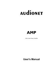
<strong>Audionet</strong> System Remote Control<br />
All functions of the MAP 1 can be controlled using the <strong>Audionet</strong> System Remote<br />
Control Harmony One. Furthermore, it is possible to control up to 14 additional devices<br />
with the Harmony One.<br />
Press key Devices to <strong>en</strong>ter Device Mode. The display now lists all devices included<br />
in the curr<strong>en</strong>t configuration of the Harmony One. Select <strong>MAP1</strong> from the list to set the<br />
Harmony One to controlling the MAP 1. Device Mode gives you access to all the<br />
possible commands to control your MAP 1. The following explains all these commands<br />
in detail.<br />
Important:<br />
• During everyday use, you should never need to use the Device Mode of your<br />
Harmony One, but control the MAP 1 (and other devices of your audio setup) by<br />
customizing your Activities. For detailed information on how to customize and use<br />
Activities on your Harmony One please consult the separate user's <strong>manual</strong> that<br />
came with your Harmony One.<br />
1<br />
5<br />
My Activities:<br />
1/2 pages<br />
List<strong>en</strong> to CDs<br />
Watch a DVD<br />
1 Power key for use with Activities, turns all devices off that are included into the<br />
curr<strong>en</strong>t Activity. See separate user's <strong>manual</strong> of Harmony One.<br />
2 Dep<strong>en</strong>ding on the operational mode, the touch scre<strong>en</strong> of the Harmony One shows a<br />
list of Activities or Devices, help or infrared commands and any available listings.<br />
3 If a m<strong>en</strong>u or listing stretches over more than one scre<strong>en</strong> page, use the corresponding<br />
arrow buttons to go to the next or previous page of the m<strong>en</strong>u or listing. (see also<br />
separate user's <strong>manual</strong> of the Harmony One).<br />
4 Devices key, lists all the devices on the display, and allows you to select and<br />
directly control any device included in the configuration of the remote control (see<br />
separate user's <strong>manual</strong> of Harmony One). Select <strong>MAP1</strong> to <strong>en</strong>ter Device Mode for<br />
controlling the MAP 1.<br />
13<br />
Mi 14:51<br />
3 3<br />
Options<br />
CD with VIPG3<br />
Devices<br />
2<br />
4
5 Activities key: Press this key to view a list of Activities you have added. Press the<br />
button next to the Activity you want to select, and the Harmony One will control<br />
your <strong>en</strong>tertainm<strong>en</strong>t system (see separate user's <strong>manual</strong> of Harmony One).<br />
Important:<br />
• The Power key is only available for Activities. In Device Mode the Power key<br />
has no function. Ev<strong>en</strong> without using an Activity, the user is able to control all<br />
functions of the MAP 1 using the Harmony One in Device Mode. The keys<br />
described below to control the MAP 1 refer to the factory default programming of<br />
the <strong>Audionet</strong> System Remote Control Harmony One. Understandably, any changes<br />
done to this setup by the user cannot be discussed here.<br />
Tip:<br />
• In order to switch the MAP 1 on/off, without using an Activity, please use the keys<br />
Power On , Power Off and/or Power Toggle scre<strong>en</strong> page 9. Of course, it is<br />
possible to control the MAP 1 without any Activity, but to tap the full pot<strong>en</strong>tial of<br />
the Harmony One you need to configure Activities customized to your needs (please<br />
refer to the separate <strong>manual</strong> of the Harmony One).<br />
Note:<br />
• Please read the separate user's <strong>manual</strong> to your <strong>Audionet</strong> System Remote Control<br />
Harmony One. Activities, Devices and Device Mode as well as customizing the<br />
remote control are discussed there.<br />
The Device Mode for MAP 1 comprises a total of 9 scre<strong>en</strong> pages containing all infrared<br />
commands. Scre<strong>en</strong> pages 1 and 2 include the corresponding keys for directly accessing<br />
the input channels of the MAP 1. All keys relevant while list<strong>en</strong>ing, you will find on<br />
scre<strong>en</strong> pages 3 to 5. If you want to change any setup options, use keys on page 6. Scre<strong>en</strong><br />
pages 7 and 8 contain commands to setup the parametric digital equalizer. On page 9<br />
you find the commands to switch the MAP 1 on/off while using the Harmony One in<br />
Device Mode.<br />
Navigate through a setup m<strong>en</strong>u of the MAP 1:<br />
Press a m<strong>en</strong>u key to <strong>en</strong>ter the corresponding m<strong>en</strong>u option. Details on every m<strong>en</strong>u item<br />
you will find in the following sections. To navigate through the m<strong>en</strong>u items, use the<br />
Ch+ and Ch- keys. Key Ch- has the same function as the set key on the front<br />
panel. To select an option, use Vol+ and Vol- keys. Vol+ works like the up key at<br />
the front panel, Vol- works like the down key.<br />
There are three ways to leave a m<strong>en</strong>u:<br />
1. Press the same m<strong>en</strong>u key again to get back to RUN mode.<br />
2. Press any other m<strong>en</strong>u key to <strong>en</strong>ter a new m<strong>en</strong>u.<br />
3. Wait for approx. 12 seconds without using any key. After this time the MAP 1 goes<br />
back to RUN mode automatically.<br />
14
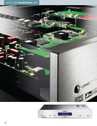
Key assignm<strong>en</strong>t MAP 1<br />
3<br />
5<br />
7<br />
8<br />
9<br />
MAP 1:<br />
1/9 pages<br />
Digital In 1<br />
Curr<strong>en</strong>t<br />
Activity<br />
Devices<br />
1 Press key Info to activate the Show function. The MAP 1 displays now<br />
information on the curr<strong>en</strong>t program format as well as output and speaker<br />
configuration. Further details on this function are in sections 'Display' and 'On<br />
Scre<strong>en</strong> Display'. In case the On Scre<strong>en</strong> Display is switched off, the OSD will be<br />
activated automatically while displaying the information after using the Info key.<br />
2 Use key Guide to switch on/off the On Scre<strong>en</strong> Display (OSD) of your MAP 1. This<br />
key has the same function as key OSD of the Harmony One.<br />
Note: The OSD is only available at video outputs Video Out in Cinch Video<br />
format (FBAS 5 ) and S-Video format (S-VIDEO 1 14 ).<br />
15<br />
Mi 14:51<br />
Digital In 3 Digital In 4<br />
Digital In 5<br />
Digital In 2<br />
Digital In 6<br />
1<br />
2<br />
4<br />
6<br />
10<br />
11
3 Vol+ , increases the volume of the MAP 1 while in RUN mode. If the MAP 1 is in<br />
one of the setup m<strong>en</strong>us, use Vol+ to select a setup option of the curr<strong>en</strong>t m<strong>en</strong>u<br />
item. This key has the same function as the key up on the front panel.<br />
4 Ch+ , switches to the next input channel while in RUN mode. If the MAP 1 is in<br />
one of the setup m<strong>en</strong>us, Ch+ goes back to the previous m<strong>en</strong>u item.<br />
5 Vol- , decreases the volume of the MAP 1 while in RUN mode. If the MAP 1 is in<br />
one of the setup m<strong>en</strong>us, use Vol- to select a setup option of the curr<strong>en</strong>t m<strong>en</strong>u item.<br />
This key has the same function as the key down on the front panel.<br />
6 Ch- , switches to the previous input channel while in RUN mode. If the MAP 1 is<br />
in one of the setup m<strong>en</strong>us, Ch- proceeds the next m<strong>en</strong>u item.<br />
7 Press to toggle muting. Muting and de-muting is done softly, i.e. volume will<br />
decrease/increase slowly.<br />
8 , starts playback. Press this key during playback to pause playback. Press again<br />
to resume from last position.<br />
9 , skips back to start of previous track.<br />
10 , skip forward to start of next track.<br />
11 , stops playback. Press key to resume playback from the start of curr<strong>en</strong>t<br />
track.<br />
Note:<br />
• Use keys 8 to 11 for USB-Audio playback control via digital Audio input 7<br />
USB AUDIO 7 . Please refer to section 'USB Audio'.<br />
Scre<strong>en</strong> page 1<br />
Use keys on scre<strong>en</strong> page 1 to access one of the first 6 digital audio inputs directly. See<br />
back panel layout to find corresponding input jacks (see section 'Overview of<br />
connections'). You will find keys to further audio inputs on scre<strong>en</strong> page 2.<br />
1<br />
MAP 1:<br />
1/9 pages<br />
Digital In 1<br />
Curr<strong>en</strong>t<br />
Activity<br />
16<br />
Digital In 2<br />
Devices<br />
Mi 14:51<br />
3 Digital In 3 Digital In 4 4<br />
5<br />
Digital In 5 Digital In 6 6<br />
2
1 Select digital audio input Digital Audio IN 1 12 directly.<br />
2 Select digital audio input Digital Audio IN 2 12 directly.<br />
3 Select digital audio input Digital Audio IN 3 12 directly.<br />
4 Select digital audio input Digital Audio IN 4 12 directly.<br />
5 Select digital audio input Digital Audio IN 5 12 directly.<br />
6 Select digital audio input Digital Audio IN 6 12 directly.<br />
Scre<strong>en</strong> page 2<br />
Use the keys on scre<strong>en</strong> page 2 to select one of the 5 remaining audio inputs of the<br />
MAP 1 directly.<br />
1<br />
MAP 1:<br />
2/9 pages<br />
Digital In 7<br />
Curr<strong>en</strong>t<br />
Activity<br />
1 Select digital audio input Digital Audio IN 7 12 directly.<br />
2 Select the external 8 channel analog audio input 8-CHANNEL ANALOG IN 10<br />
directly.<br />
3 Select digital audio input USB AUDIO 7 directly.<br />
4 Select analog audio input Analog In LEFT 1 / RIGHT 1 9 directly.<br />
5 Select analog audio input Analog In LEFT 2 / RIGHT 2 9 directly.<br />
17<br />
Ext. 8ch In<br />
Devices<br />
Mi 14:51<br />
3 USB Audio In Analog In 1 4<br />
2<br />
Analog In 2 5
Scre<strong>en</strong> page 3<br />
MAP 1:<br />
3/9 pages<br />
Curr<strong>en</strong>t<br />
Activity<br />
1 Press key Dyn. Range to <strong>en</strong>ter Dynamic Range m<strong>en</strong>u. Use keys Vol+ and<br />
Vol- to select desired dynamic range:<br />
Maximum: full dynamic range, no compression at all<br />
Standard: medium dynamic range, moderate compression<br />
Minimum: minimal dynamic range, full compression<br />
Note: This m<strong>en</strong>u is only available, if Internal Decoder is set to Multichannel.<br />
2 Press key EQ to switch on/off the double precision parametric digital equalizer.<br />
3 Use key Dolby / DTS Mode to <strong>en</strong>ter Decoder Setup m<strong>en</strong>u. Here you select the<br />
desired mode for Dolby Pro Logic IIx und DTS ** Neo:6. Additionally, you choose<br />
betwe<strong>en</strong> Dolby Pro Logic IIx and DTS Neo:6 processing on stereo PCM signals in<br />
List<strong>en</strong>ing Modes <strong>Audionet</strong> D8, 3 Stereo or Phantom. For more detailed<br />
description refer to sections 'Setup' and 'M<strong>en</strong>u Decoder Setup'.<br />
Note: Navigate through the m<strong>en</strong>u using keys Ch+ / Ch- . Change options<br />
with keys Vol- / Vol+ .<br />
4 Use key PCM Direct to switch activate/de-activate PCM Direct mode. If active,<br />
the name of the curr<strong>en</strong>tly selected input channel in the display is replaced by<br />
---PCM Direct---.<br />
Note: You can only activate PCM Direct mode, if a stereo PCM signal is<br />
available at the curr<strong>en</strong>t audio input. While in PCM Direct mode, the internal<br />
decoder (and therefore Bass Manager, any matrix surround processing etc.) is deactivated<br />
temporarily in order to playback stereo PCM material purely as recorded<br />
and without any changes. To leave PCM Direct mode press PCM Direct again.<br />
If a signal other than stereo PCM is detected at the curr<strong>en</strong>t input, PCM Direct<br />
mode is switched off automatically. The display informs the user with the message<br />
PCM Direct off. PCM Direct mode cannot be activated if the MAP 1<br />
receives digital data from an <strong>Audionet</strong> source using the HighBit interface.<br />
18<br />
Dynamic<br />
Range<br />
Devices<br />
Mi 14:51<br />
Dolby / DTS<br />
2 EQ<br />
Mode<br />
3<br />
4<br />
PCM Direct<br />
1<br />
List<strong>en</strong>ing<br />
Mode 5
5 Press key List<strong>en</strong>ing Mode to select the desired List<strong>en</strong>ing Mode. See section<br />
'List<strong>en</strong>ing Mode' for further details.<br />
Scre<strong>en</strong> page 4<br />
1<br />
MAP 1:<br />
4/9 pages<br />
Front<br />
Curr<strong>en</strong>t<br />
Activity<br />
1 Press key Front to <strong>en</strong>ter the volume setup m<strong>en</strong>u for refer<strong>en</strong>ce level<br />
(Front Left). Adjust the refer<strong>en</strong>ce volume level for system level setup using the<br />
keys Vol+ and Vol- .<br />
2 Press key C<strong>en</strong>ter to adjust the volume level of the C<strong>en</strong>ter channel using keys<br />
Vol+ and Vol- (+12...-18dB).<br />
3 Press key Surround to adjust the volume level of the Surround channels using<br />
keys Vol+ and Vol- (+12...-18dB).<br />
4 Press key Back to adjust the volume level of the Back Surround channels using<br />
keys Vol+ and Vol- (+12...-18dB).<br />
5 Press key Sub to adjust the volume level of the Subwoofer channel using keys<br />
Vol+ and Vol- (+12...-24dB).<br />
6 Press key LFE to adjust the volume level of the LFE channel using the keys<br />
Vol+ and Vol- (+0...-10dB). This function affects only the LFE channel before<br />
it is processed by the Bass Manager.<br />
Use they keys on scre<strong>en</strong> page 4 to adjust the volume levels of all output channels of<br />
your MAP 1. As soon as you press one of the keys, the MAP 1 <strong>en</strong>ters the volume<br />
adjustm<strong>en</strong>t m<strong>en</strong>u Level Setup. The level of the left front channel is the refer<strong>en</strong>ce level<br />
of the whole system. The volume levels of all other channel are adjusted in refer<strong>en</strong>ce to<br />
it. Therefore, if the left front channel Front Left is selected for adjustm<strong>en</strong>t the<br />
volume keys Vol- / Vol+ change the master volume of the system, not just the level<br />
of the left front channel alone.<br />
Tip:<br />
• In order to adjust all volume levels correctly you should therefore always start with<br />
the left front channel to set the refer<strong>en</strong>ce level for the whole system, especially if<br />
you are using an SPL meter to adjust volume levels.<br />
19<br />
C<strong>en</strong>ter<br />
Devices<br />
Mi 14:51<br />
3 Surround Back<br />
4<br />
5<br />
Sub LFE 6<br />
2
If this refer<strong>en</strong>ce level is set correctly, you are able to adjust the volume levels of all<br />
other channels easily. Use key Ch- to skip to the level adjustm<strong>en</strong>t of the next channel.<br />
Or use key Ch+ to return to adjusting the previous channel. To change the respective<br />
volume use keys Vol- / Vol+ . Alternatively, you can use the keys 1 to 6 on scre<strong>en</strong><br />
page 4 to select the channel to be adjusted directly.<br />
By pressing keys Surround or Back the level is adjusted for both channels of the<br />
corresponding channel group Surround or Back. So these keys are mainly used for<br />
changing levels of the Surround or Back channels during list<strong>en</strong>ing. You can adjust the<br />
levels of each channel group without changing their stereo balance. In any case you can<br />
always get to the next/previous channel by using the key Ch+ / Ch- .<br />
Scre<strong>en</strong> page 5<br />
1<br />
MAP 1:<br />
5/9 pages<br />
Digital Rec<br />
Select<br />
Curr<strong>en</strong>t<br />
Activity<br />
1 Press key DigiRec Select to decide which signal is routed to the digital outputs.<br />
Use keys Vol- and Vol+ to select digital input is output at the digital output<br />
jacks Digital Audio OUT 13 indep<strong>en</strong>d<strong>en</strong>tly from the curr<strong>en</strong>t input channel. The<br />
digital signal is always available in both formats coaxial and optical. To switch off<br />
the digital outputs select No Digital In. Choose option Tied to Dig. In<br />
to route the curr<strong>en</strong>tly selected digital input to the digital outputs respectively.<br />
2 Press key Dim Display , th<strong>en</strong> adjust the display brightness with keys Vol+ and Vol- .<br />
Note: During adjustm<strong>en</strong>t the display stays at 100% brightness for better<br />
readability. The new selected brightness will be set after returning to RUN mode<br />
my pressing Dim Display again or just waiting for approx. 12 seconds without<br />
any new command input. If the display brightness is set to Off the display is only<br />
activated while making any adjustm<strong>en</strong>t in the setup m<strong>en</strong>us. It will switch off some<br />
seconds after the last change of settings.<br />
20<br />
Dim Display<br />
Devices<br />
Mi 14:51<br />
3 Digital Filter OSD<br />
4<br />
5<br />
Load Settings Save Settings 6<br />
2
3 Press key Digital Filter to select the digital filter. Use keys Vol- and Vol+ to<br />
choose betwe<strong>en</strong> 4 differ<strong>en</strong>t oversampling filters for the front channels Left/Right:<br />
<strong>Audionet</strong>: special digital oversampling filter with short pre-ringing<br />
Lagrange: short Lagrange filter<br />
Blackman: digital filter by Blackman<br />
Kaiser: digital filter by Kaiser.<br />
Note: This option is only available for sample rates up to 48 kHz and not for<br />
DVD Audio using the HighBit interface.<br />
You distinguish the four digital oversampling filters from each other by their<br />
impulse responses (see diagrams). Use the filter that suits your list<strong>en</strong>ing<br />
prefer<strong>en</strong>ces. Do not hesitate to experim<strong>en</strong>t with the differ<strong>en</strong>t filter settings.<br />
4 Use key OSD to switch on/off the On Scre<strong>en</strong> Display (OSD) of your MAP 1. This<br />
key has the same function as key Guide of the Harmony One.<br />
Note: The OSD is only available at video outputs Video Out in Cinch Video<br />
format (FBAS 5 ) and S-Video format (S-VIDEO 1 14 ).<br />
5 Press key Load Setting to re-load previously saved user settings. Select the user<br />
setting you like to load by using the keys Vol- and Vol+ . Press to load<br />
selected user setting. All curr<strong>en</strong>t settings will be overwritt<strong>en</strong> during load.<br />
You can choose a name up to 14 characters in l<strong>en</strong>gth for each of the 30 user<br />
settings. To change a name press key Ch+ . A cursor marks the character to be<br />
changed by pressing Vol- or Vol+ (see also Edit Channel Name). Move<br />
cursor one position to the right by pressing . While the cursor is active, you get<br />
21
to the names of the other user settings with keys Ch+ and Ch- . To leave edit<br />
mode press Load Setting again.<br />
6 To save the curr<strong>en</strong>t settings as user setting press key Save Setting , and choose<br />
one of the 30 memory spaces with the Vol- and Vol+ keys. All data at the<br />
corresponding memory location is overwritt<strong>en</strong> by the curr<strong>en</strong>t settings after pressing<br />
the key.<br />
You can simply assign the curr<strong>en</strong>t user setting to only one input channel or ev<strong>en</strong> to<br />
all input channels at once. Press Ch+ and select the input channel with Vol- or<br />
Vol+ . Th<strong>en</strong> press to transfer the curr<strong>en</strong>t settings to the selected input channel.<br />
Press Ch+ again to <strong>en</strong>ter mode to assign curr<strong>en</strong>t settings to all input channels.<br />
Press to start data transfer.<br />
A user setting comprises: Volume and balance levels of all output channels,<br />
PCM Direct mode status, dynamic range, Dolby Pro Logic IIx and DTS Neo:6<br />
mode, List<strong>en</strong>ing Mode and Digital Filter. 30 memory locations for storing user<br />
settings are available. The user can assign a name up to 14 characters in l<strong>en</strong>gth to<br />
each user setting. Additionally, each of the 12 input channels saves automatically<br />
all curr<strong>en</strong>t settings indep<strong>en</strong>d<strong>en</strong>tly (channel settings). The 30 memory locations (user<br />
settings) can only be accessed by the user wh<strong>en</strong> using the Save Setting<br />
function. So they are indep<strong>en</strong>d<strong>en</strong>t from the channel settings.<br />
Note: Curr<strong>en</strong>t master volume, speaker settings, state of internal decoder, video<br />
options etc. are saved automatically and indep<strong>en</strong>d<strong>en</strong>tly wh<strong>en</strong> changing a setting<br />
and/or switching off the MAP 1.<br />
Note: After adjusting the volume levels of all output channels we recomm<strong>en</strong>d<br />
to save these found settings to all input channels as a simple start up for further<br />
channel or source dep<strong>en</strong>d<strong>en</strong>t level settings. To save the curr<strong>en</strong>t level settings to all<br />
input channels press the following keys:<br />
Save Setting Ch- <br />
Now all input channels have the same volume level settings. Of course, you can<br />
change these settings easily for each input channel indep<strong>en</strong>d<strong>en</strong>tly, if necessary.<br />
22
Scre<strong>en</strong> page 6<br />
1<br />
MAP 1:<br />
6/9 pages<br />
Channel<br />
Setup<br />
Curr<strong>en</strong>t<br />
Activity<br />
1 Channel Setup <strong>en</strong>ters the Channel Setup m<strong>en</strong>u.<br />
2 Bass Manager <strong>en</strong>ters the Bass Manager m<strong>en</strong>u.<br />
3 Global Setup <strong>en</strong>ters the Global Setup m<strong>en</strong>u.<br />
4 Delay Manager <strong>en</strong>ters the Delay Manager m<strong>en</strong>u.<br />
5 Video Setup <strong>en</strong>ters the Video Setup m<strong>en</strong>u.<br />
6 Press key TestTone to start the internal test tone g<strong>en</strong>erator. The g<strong>en</strong>erator<br />
delivers a noise signal to the Front Left channel. You can now adjust the refer<strong>en</strong>ce<br />
level with keys Vol- / Vol+ as described above. Press key Ch- to produce the<br />
noise signal in the next channel. Or use key Ch+ to skip back to the previous<br />
channel. Ch- moves the noise signal clockwise (according to your speaker<br />
positions in your list<strong>en</strong>ing room) from one channel to the other, Ch+ selects the<br />
channels anti clockwise. Adjust the level of each selected channel so that all<br />
channels reproduce the noise signal of the test tone g<strong>en</strong>erator with the same volume.<br />
Press TestTone again to switch off the test tone g<strong>en</strong>erator and return to RUN<br />
mode.<br />
Note: No test tone is available on the Subwoofer output!<br />
Scre<strong>en</strong> page 7<br />
All 8 keys on scre<strong>en</strong> pages 7 and 8 are used to configure the parametric, digital<br />
equalizer. If the MAP 1 is in any other mode than the setup mode for the equalizer,<br />
pressing one of the 8 keys invokes the setup mode for the equalizer. Th<strong>en</strong> the keys have<br />
the following functions:<br />
Key Ch- selects the next channel, key Ch+ the previous channel. While in the<br />
equalizer setup mode you are still able to adjust the master volume using keys Vol- /<br />
Vol+ .<br />
23<br />
Bass<br />
Manager<br />
Devices<br />
Mi 14:51<br />
Delay<br />
3 Global Setup<br />
Manager 4<br />
5<br />
Video Setup Test Tone 6<br />
2
Leave the equalizer setup mode by using one of the other setup m<strong>en</strong>u keys. The MAP 1<br />
th<strong>en</strong> <strong>en</strong>ters the corresponding m<strong>en</strong>u. If you wait for approx. 12 seconds without pressing<br />
any key, the MAP 1 will return to RUN mode automatically.<br />
1 MPE- selects the previous MPE *) filter of the curr<strong>en</strong>t channel.<br />
2 MPE+ selects the next MPE filter of the curr<strong>en</strong>t channel.<br />
3 Freq- decreases the c<strong>en</strong>ter frequ<strong>en</strong>cy of the curr<strong>en</strong>t MPE filter.<br />
4 Freq+ increases the c<strong>en</strong>ter frequ<strong>en</strong>cy of the curr<strong>en</strong>t MPE filter.<br />
*) MPE = Minimum Phase Equalizer<br />
Scre<strong>en</strong> page 8<br />
MAP 1:<br />
7/9 pages<br />
Curr<strong>en</strong>t<br />
Activity<br />
1 Q- decreases the Q-factor of the curr<strong>en</strong>t MPE filter.<br />
2 Q+ increases the Q-factor of the curr<strong>en</strong>t MPE filter.<br />
3 Gain- decreases the gain factor of the curr<strong>en</strong>t MPE filter.<br />
4 Gain+ increases the gain factor of the curr<strong>en</strong>t MPE filter.<br />
24<br />
Devices<br />
Mi 14:51<br />
1 MPE- MPE+<br />
2<br />
3<br />
MAP 1:<br />
8/9 pages<br />
Freq- Freq+ 4<br />
Curr<strong>en</strong>t<br />
Activity<br />
Devices<br />
Mi 14:51<br />
1 Q- Q+<br />
2<br />
3<br />
Gain- Gain+ 4
Tip:<br />
• For further information on the use and configuration of an parametric, digital<br />
equalizer please refer to the docum<strong>en</strong>tation of the analyser software CARMA which<br />
is available for download free of charge on our internet site www.audionet.de.<br />
Scre<strong>en</strong> page 9<br />
2<br />
MAP 1:<br />
9/9 pages<br />
Power<br />
Toggle<br />
Curr<strong>en</strong>t<br />
Activity<br />
1 If the MAP 1 is in stand-by mode, press key Power On to switch the unit on.<br />
2 Use Power Toggle to switch on/off the MAP 1. This key has the same function<br />
as the key power on the front panel. If the MAP 1 is in stand-by mode,<br />
Power Toggle will switch on the unit. If the MAP 1 is already switched on,<br />
Power Toggle will switch off the unit to stand-by mode.<br />
3 If the MAP 1 is switched on, use key Power Off to switch the unit off to stand-by<br />
mode.<br />
25<br />
Power On<br />
Devices<br />
Mi 14:51<br />
1<br />
Power Off 3
Setup<br />
Description of all m<strong>en</strong>u items<br />
RUN mode:<br />
This is the normal operation mode, if no m<strong>en</strong>u is selected. Use Vol- and Vol+ keys<br />
to adjust the master volume. The display shows name and number of the selected input<br />
channel in the 2 nd line. The 3 rd line shows the curr<strong>en</strong>t volume (see chapter 'Display').<br />
Select Input:<br />
Use up and down keys to select desired input channel. The input channels are aligned in<br />
the following order: Digital In 1 to 7 12 , USB 7 , External 8ch In 10 and Analog<br />
In 1 and 2 9 .<br />
List<strong>en</strong>ing Mode:<br />
Use Vol- and Vol+ keys to select the List<strong>en</strong>ing Mode for Dolby Digital, Dolby Pro<br />
Logic IIx, DTS decoding or DVD Audio (via <strong>Audionet</strong> HighBit Interface).<br />
Mono: all program material is downmixed to mono<br />
Stereo: reproduces 2-channel source material as 2-ch Stereo, turns off Dolby<br />
Pro Logic IIx or DTS Neo:6 decoding, any other multichannel material<br />
is downmixed to Stereo output (2/0 Lo/Ro). Mono signals are re-routed<br />
from the C<strong>en</strong>ter channel to both Front Left and Right channels.<br />
Phantom: information on the C<strong>en</strong>ter channel is re-routed to Front Left and Right channels<br />
3Stereo: reproduces audio programs using only the three front channels (L,C,R)<br />
Surround: reproduces all channels originally available in the program material, 2-channel<br />
Stereo is reproduced as Stereo (see table 'Overview List<strong>en</strong>ing Modes').<br />
<strong>Audionet</strong> D8: reproduces all available channels of the program material. Additionally,<br />
material with stereo <strong>en</strong>coded surround channels is always ext<strong>en</strong>ded to 7.1<br />
channels. 2-channel Stereo is expanded by Dolby Pro Logic IIx or DTS<br />
Neo:6 to 6.1 or 7.1 channels (see table 'Overview List<strong>en</strong>ing Modes').<br />
Party Mode: all input material is downmixed to 2-channel Stereo and distributed to<br />
all available speakers as follows:<br />
Front Left = Surround Left = Back Left<br />
Front Right = Surround Right = Back Right<br />
C<strong>en</strong>ter = ½ Front Left + ½ Front Right<br />
Note: With this List<strong>en</strong>ing Mode mono signals can be reproduced in<br />
every speaker.<br />
Lt/Rt out: all program material is downmixed to Stereo output (2-ch Lt/Rt) for<br />
later Dolby Pro Logic IIx or DTS Neo:6 decoding (recomm<strong>en</strong>ded for<br />
recording Dolby Digital / DTS programs on 2-channel recording<br />
devices like VCRs)<br />
26
Note:<br />
This m<strong>en</strong>u is only available, if Internal Decoder is set to Multi-Channel or<br />
DVD Audio playback.<br />
Overview List<strong>en</strong>ing Modes:<br />
Program <strong>Audionet</strong> D8 Surround<br />
PCM<br />
Dolby Digital 2/0<br />
(not Surround <strong>en</strong>coded)<br />
Dolby Digital 2/0<br />
(Surround <strong>en</strong>coded)<br />
DTS 2/0<br />
(not Surround <strong>en</strong>coded)<br />
DTS 2/0<br />
(Surround <strong>en</strong>coded)<br />
2-Channel formats<br />
Dolby Pro Logic IIx 2) or<br />
4) 1)<br />
DTS Neo:6<br />
27<br />
Stereo PCM<br />
Dolby Digital + Pro Logic IIx 2) Dolby Digital 2/0<br />
Dolby Digital + Pro Logic IIx 2) Dolby Digital + Pro Logic IIx 2)<br />
DTS Neo:6 3) DTS 2/0<br />
DTS Neo:6 3) DTS Neo:6 3)<br />
Multi channel formats<br />
Dolby Digital Dolby Digital + Pro Logic IIx 2) Dolby Digital 5)<br />
DTS DTS + Neo:6 4) DTS 5)<br />
Dolby Digital<br />
(Dolby Surround EX <strong>en</strong>coded)<br />
Dolby Digital + Pro Logic IIx 2) Dolby Digital EX 6)<br />
DTS-ES Matrix DTS-ES Matrix 4) DTS-ES Matrix 4)<br />
DTS-ES Discrete DTS-ES Discrete 4) DTS-ES Discrete 4)<br />
DTS 96/24 DTS 96/24 + D8 7) DTS 96/24 5)<br />
*1) The decoder mode is defined by the function Convert 2-ch PCM to in m<strong>en</strong>u Decoder Setup (see chapter<br />
'Setup', section 'Decoder Setup'). Additional options are available by function Set Dolby Pro Logic<br />
IIx Mode for 2-Channel or Set DTS Neo:6 Mode (see chapter 'Setup', section 'Decoder Setup').<br />
*2) The decoder delivers a 7-channel output. The Back Surround speakers playback a stereo signal.<br />
*3) The decoder delivers a 6-channel output. The Back Surround speakers playback a mono signal each.<br />
*4) same as 3). Additional options by function Set DTS Neo:6 Mode<br />
(see chapter 'Setup', section 'Decoder Setup').<br />
*5) The decoder delivers a 5-channel output. The Back Surround speakers playback no signals.<br />
*6) same as 3). Additional options by function Dolby Digital EX Mode<br />
(see chapter 'Setup', section 'Decoder Setup').<br />
*7) The decoder delivers a 5-channels output. Additionally, the Back Surround speakers playback the signals of the<br />
Surround speakers.
M<strong>en</strong>u Channel Setup<br />
This m<strong>en</strong>u comprises all settings, that are valid only for the curr<strong>en</strong>t selected input<br />
channel. If you change the input channel, all settings are saved automatically and the<br />
channel settings for the new channel are loaded. Therefore, you can adjust the MAP 1 to<br />
each connected source indep<strong>en</strong>d<strong>en</strong>tly, and don't have to worry about saving and reloading<br />
the settings you made. The MAP 1 will do the work automatically.<br />
Internal Decoder:<br />
In order to switch off the internal decoder, press key Vol- (the display shows pure<br />
2-channnel). All program material is downmixed to 2-ch Stereo indep<strong>en</strong>d<strong>en</strong>tly from<br />
the original program format. Dolby Pro Logic IIx or DTS Neo:6 decoding, bass and<br />
delay managem<strong>en</strong>t are off in this mode. It is strongly recomm<strong>en</strong>ded to use this mode for<br />
Stereo PCM or 2-channel analog sources only.<br />
Press key Vol+ to activate the internal decoder (the display shows Multi-<br />
Channel). All incoming program formats (PCM or bitstream) are detected and<br />
decoded automatically (see also section 'PCM direct').<br />
Note:<br />
• The internal decoder can be activated for all audio inputs except the external 8channel<br />
analog input (External 8ch).<br />
• If the internal decoder is active for a 2-channel analog audio input, the input signals<br />
are internally converted from analog to digital. Now all functions like Dolby Pro<br />
Logic IIx or DTS Neo:6 decoding, bass and delay managem<strong>en</strong>t, digital equalizer etc<br />
are available as for any digital audio input.<br />
• The internal analog to digital converter has an input s<strong>en</strong>sitivity of 2 VRMS. If input<br />
signals exceed this level, the converter will overload causing audible distortions. In<br />
this case, reduce the output level of the unit connected to the MAP 1 until no<br />
overload occurs.<br />
Set Video Input:<br />
You can assign one of the video inputs (2 cinch video inputs 4 , 2 S-Video inputs 15 ,<br />
1 DVI input 3 , 1 alternative YUV/RGB input) to each input channel indep<strong>en</strong>d<strong>en</strong>tly.<br />
Ev<strong>en</strong> multiple assignm<strong>en</strong>ts are allowed (e.g. for connecting a DVD player that uses<br />
more than one audio output). If no video input is needed for an audio input, please<br />
select No Video Input.<br />
No Video Input No video input is selected.<br />
Video In1 or In2 The corresponding video input IN1 or IN2 4 is selected.<br />
S-Video In1 or In2 The corresponding S-Video input S-VIDEO IN1 or<br />
S-VIDEO IN2 15 is selected.<br />
DVI-Int. In The video input 3 is used for analog and digital DVI<br />
signals (DVI-I) which are routed directly to the DVI<br />
output 16 .<br />
Cinch Analog The video inputs 4 and video output 5 are re-defined<br />
in their function to be used for compon<strong>en</strong>t video input.<br />
28
Their analog signals are routed directly to the analog<br />
part of DVI output 16 .<br />
Note:<br />
• If you assign any of the Cinch (or Composite) video inputs 4 to an audio input, you<br />
will have a video signal at the Cinch/Composite video output 5 as well as at the<br />
S-Video output 14 (automatically converted by the internal 'Cinch-to-S-Video<br />
Converter').<br />
• If the optional Progressive Scan Card is inserted, some more video inputs and<br />
options are available. In this case, please refer to chapter 'Progressive Scan Card'<br />
for more detailed information.<br />
• This m<strong>en</strong>u item is located in the m<strong>en</strong>u Channel Setup, as it is a setting, that can be<br />
selected for each input channel indep<strong>en</strong>d<strong>en</strong>tly. Although the m<strong>en</strong>u Video Setup<br />
deals with global video settings, the same function Set Video Input, as described<br />
above, is also integrated into the Video Setup m<strong>en</strong>u, simply for an easier access.<br />
• For each audio input the corresponding video input is assigned individually. To<br />
simplify this procedure, select the desired video input for each audio input during<br />
the setup (of channel levels, names, decoder settings etc) for this audio input.<br />
Offset Adjust:<br />
Use Vol- and Vol+ keys to adjust the input channel offset. You can add gain or<br />
att<strong>en</strong>uate each input channel individually within a range of +9...-9dB in order to<br />
comp<strong>en</strong>sate differ<strong>en</strong>t output levels of sources connected to the MAP 1.<br />
Set List<strong>en</strong>ing Mode:<br />
This m<strong>en</strong>u item has the same function as the key List<strong>en</strong>ing Mode on the remote<br />
control described above.<br />
Digital Filter:<br />
This m<strong>en</strong>u item has the same function as the key Digital Filter on the remote control<br />
described above.<br />
Dynamic Range:<br />
This m<strong>en</strong>u item has the same function as the key Dynamic Range of the remote<br />
control described above.<br />
Set Dual Mono:<br />
Select the preferred playback mode for DVD soundtracks in Dual Mono mode with the<br />
Vol- and Vol+ keys.<br />
CH1+CH2: Both Dual Mono channels are reproduced<br />
CH1 only:: Only Dual Mono channel 1 is reproduced<br />
CH2 only: Only Dual Mono channel 2 is reproduced<br />
Note:<br />
• This m<strong>en</strong>u is only available, if Internal Decoder is set to Multi-Channel.<br />
29
Edit Channel Name:<br />
While in m<strong>en</strong>u Channel Setup proceed to this m<strong>en</strong>u item by pressing key Ch- if<br />
m<strong>en</strong>u item Set Dual Mono Mode is highlighted, or by pressing Ch+ while m<strong>en</strong>u<br />
item Set Decoder is highlighted.<br />
For each input channel you can choose a name up to 14 characters in l<strong>en</strong>gth. A cursor<br />
(↑) marks the curr<strong>en</strong>t character to be changed by pressing Vol- and Vol+ keys. Press<br />
key to move the cursor to the right onto the next character position. At the <strong>en</strong>d of<br />
the character string the cursor jumps back to the first position after pressing the key .<br />
M<strong>en</strong>u Decoder Setup<br />
Use this m<strong>en</strong>u to select the desired operating modes and options for Dolby Pro Logic<br />
IIx and DTS Neo:6 decoding.<br />
Note:<br />
• This m<strong>en</strong>u is only available, if the internal Decoder is active (option Internal<br />
Decoder is set to Multi-channel).<br />
Set Dolby Pro Logic IIx Mode:<br />
Dolby Pro Logic IIx expands original 2- or 5.1-channel material to 6.1- or 7.1-channel<br />
output using a matrix technology. Dep<strong>en</strong>ding on the original format the following<br />
options are available:<br />
M<strong>en</strong>u item for Multi-Channel:<br />
Select the preferred mode for expanding 5.1-channel program material to 6.1- or 7.1channels<br />
using Dolby Pro Logic IIx by using the Vol- and Vol+ keys:<br />
Movie: The Movie mode is optimal for 5.1-channel movie soundtracks or<br />
stereo soundtracks that are Dolby Surround <strong>en</strong>coded.<br />
Music: Not all 5.1 material may sound ideal wh<strong>en</strong> decoded with Dolby Pro<br />
Logic IIx in the Movie mode. Use mode Music if the soundfield is<br />
focused too much on the Back Surround speakers.<br />
Dolby D EX: Dolby Digital EX creates six full-bandwidth output channels from 5.1channel<br />
sources. This is done using a matrix decoder that derives three<br />
surround channels from the two in the original recording.<br />
M<strong>en</strong>u item for 2-Channel:<br />
Dolby Pro Logic IIx offers 4 differ<strong>en</strong>t modes for decoding 2-channel sources. Select<br />
your preferred mode with the Vol- and Vol+ keys:<br />
Movie: The Movie mode is for use with stereo TV shows and all Dolby Surround<br />
<strong>en</strong>coded programs. The result is an <strong>en</strong>hanced soundfield directionality that<br />
approaches the quality of discrete 5.1-channel sound.<br />
Music: The Music mode is for use with any stereo music recordings, and<br />
provides a wide and deep sound space. The Music mode includes controls<br />
(C<strong>en</strong>terWidth, Dim<strong>en</strong>sionControl and Panorama), that allow the sound to<br />
30
e tailored to your list<strong>en</strong>ing tastes. All three of these controls may be used<br />
alone or in any combination. After you experim<strong>en</strong>ted with them on a few<br />
programs, you will easily understand their effect and consider which<br />
setting you may prefer.<br />
Pro Logic: Original Dolby Pro Logic mode.<br />
Matrix: The Matrix mode is the same as the Music mode except, that the<br />
directional <strong>en</strong>hancem<strong>en</strong>t logic is turned off. It may be used to <strong>en</strong>hance<br />
mono signals by making them seem 'larger'. The Matrix mode may also<br />
find use, if fluctuations from poor stereo reception (of FM radio, TV or<br />
satellite receivers) cause disturbing surround signals from a logic decoder.<br />
Because music recording techniques and list<strong>en</strong>ing prefer<strong>en</strong>ces vary so widely, no single<br />
decoding setting is likely to be adequate for all cont<strong>en</strong>t. Therefore, Dolby Pro Logic IIx<br />
incorporates a separate Music mode to reproduce a convincing and compelling<br />
surround ambi<strong>en</strong>ce from conv<strong>en</strong>tional stereo sources. The Music mode g<strong>en</strong>erally<br />
includes three controls for fine-tuning the soundfield to get the most pleasing or natural<br />
effect.<br />
Note:<br />
• These options are only available, if the Internal Decoder is set to Multi-<br />
Channel and the Dolby Pro Logic IIx mode Music is selected. Use key Ch-<br />
while m<strong>en</strong>u item Dolby Pro Logic IIx Mode for 2-Channel is<br />
selected:<br />
C<strong>en</strong>ter Width (OSD: Cntr Width):<br />
This control allows c<strong>en</strong>ter channel sounds to be positioned betwe<strong>en</strong> the C<strong>en</strong>ter speaker<br />
and the Left/Right speakers over a range of 8 steps. Step 3 uses a combination of all<br />
three front speakers to give the best vocal imaging and most seamless soundstage<br />
pres<strong>en</strong>tation, and is recomm<strong>en</strong>ded for most recordings. Step 0 places all c<strong>en</strong>ter sound in<br />
the C<strong>en</strong>ter speaker. Step 7 places all c<strong>en</strong>ter sound equally in the Left/Right speakers,<br />
just as in conv<strong>en</strong>tional stereo. The C<strong>en</strong>ter Width control is automatically preset to 3 in<br />
the Movie mode.<br />
Note:<br />
• This m<strong>en</strong>u item is only available, if the Internal Decoder is set to Multi-<br />
Channel and the Dolby Pro Logic IIx Mode Music is selected.<br />
Dim<strong>en</strong>sion Control (OSD: Dim<strong>en</strong>sion):<br />
This control allows the user to gradually adjust the soundfield either towards the front<br />
or towards the rear. This can be useful to help achieve the desired balance from all the<br />
speakers with certain recordings, that may contain either too much or too little spatial<br />
effect. Step 0 is the recomm<strong>en</strong>ded setting, which has no effect on the sound. Steps 1, 2<br />
and 3 gradually move the sound forward, and steps -1, -2, -3 move the sound towards<br />
the surrounds. The Dim<strong>en</strong>sion control is automatically preset to 0 in the Movie mode.<br />
31
Note:<br />
• This m<strong>en</strong>u item is only available, if the Internal Decoder is set to Multi -<br />
Channel and the Dolby Pro Logic IIx Mode Music is selected.<br />
Panorama:<br />
This control ext<strong>en</strong>ds the front stereo image to include the surround speakers for an<br />
exciting 'wraparound' effect with side wall imaging. It is particularly effective for<br />
recordings which have strong left or right channel elem<strong>en</strong>ts in the mix, as these are<br />
detected and acc<strong>en</strong>tuated by the Panorama process. The Panorama control is<br />
automatically turned off in Movie mode.<br />
Note:<br />
• This m<strong>en</strong>u item is only available, if the Internal Decoder is set to Multi-<br />
Channel and the Dolby Pro Logic IIx Mode Music is selected.<br />
Set Neo:6 Mode (OSD: DTS Neo:6 Mode):<br />
DTS Neo:6 g<strong>en</strong>erates a 6-channel soundfield from an original 2-channel source using a<br />
matrix technology. Two user selectable modes are available:<br />
Cinema: The Cinema mode is suitable for matrix <strong>en</strong>coded stereo source material<br />
(like movie or TV soundtracks).<br />
Music: Use the Neo:6 mode Music for stereo music material, that did not use any<br />
surround matrix <strong>en</strong>coding technologies during recording. Neo:6 produces a<br />
soundfield with up to 6 channels, that does not diminish the subtleties and<br />
integrity of the original stereo recording.<br />
Set Neo:6 Option Cgain (OSD: CntrGain):<br />
If the DTS Neo:6 mode Music is selected, the user can influ<strong>en</strong>ce and, by using the<br />
option Cgain, adjust the soundfield to his list<strong>en</strong>ing prefer<strong>en</strong>ces. Cgain changes the<br />
amount of C<strong>en</strong>ter signals mixed to the Left and Right channels. The C<strong>en</strong>ter channel<br />
level is not influ<strong>en</strong>ced by setting Cgain.<br />
The user can adjust Cgain from 0.0 to 0.5 in steps of 0.1. If Cgain = 0.0, the Left<br />
and Right channels are played back unchanged referring to the original stereo mix. The<br />
higher the value of Cgain, the more dominant is the sound of the C<strong>en</strong>ter channel.<br />
M<strong>en</strong>u item Convert 2-Ch PCM to:<br />
Use keys Vol- and Vol+ to select the desired matrix decoder technology to expand<br />
stereo PCM signals to 6 or 7 channels:<br />
Dolby PLIIx: Select this option to use Dolby Pro Logic IIx. The options selected by<br />
function Dolby PL IIx Mode for 2-Ch are used (see above).<br />
DTS Neo:6: Select this option to use DTS Neo:6. The settings from function DTS<br />
Neo:6 Mode are applied (see above).<br />
32
M<strong>en</strong>u Global Setup<br />
This m<strong>en</strong>u adjusts global options for the MAP 1, which are saved automatically wh<strong>en</strong><br />
switching off the unit to stand by mode and re-loaded automatically wh<strong>en</strong> switching on.<br />
Select the Global Setup m<strong>en</strong>u by pressing key Global Setup .<br />
Note:<br />
• The first selected m<strong>en</strong>u item of the On Scre<strong>en</strong> Display is always Output Phase<br />
although it is not the top item. The reason is, that the first two items in the m<strong>en</strong>u<br />
both are accessible directly via keys on the remote control. Of course, you can select<br />
both items using the keys Ch+ / Ch- to navigate through the m<strong>en</strong>u.<br />
Output Phase:<br />
Press Vol+ key to invert the phase of all output channels (inverted). Use this<br />
option for CDs, that were recorded with inverted phase. Press Vol- key to set phase<br />
back to normal.<br />
Set Standby-Text:<br />
With this option you can specify how the stand by mode is shown in the display. There<br />
are following possibilities to choose:<br />
Dot: Please press the Vol- key. The stand by mode is indicated by a little point<br />
in the display.<br />
Off: Please press the Vol+ key. The stand by mode is indicated by the text off<br />
in the display.<br />
Note:<br />
• In both cases the display position of the stand by text changes every 12 seconds in a<br />
random pattern to prev<strong>en</strong>t a 'burn in' of the display.<br />
Set AutoStart:<br />
To <strong>en</strong>able the AutoStart option press Vol+ key (On), to disable press Vol- key<br />
(Off). If the AutoStart option is active, the MAP 1 will start up automatically wh<strong>en</strong><br />
connected to mains. Use this option, if you want to start up the MAP 1 by timer.<br />
Dolby Digital EX Mode:<br />
Use keys Vol- and Vol+ to select, if for List<strong>en</strong>ing Mode Surround, Dolby<br />
Surround EX <strong>en</strong>coded bitstreams are recognized and played back in Dolby Digital EX<br />
mode automatically, or if they are played back like plain Dolby Digital bitstreams:<br />
auto on: The 'Dolby Surround EX <strong>en</strong>coded' flag in the bitstream is recognized<br />
and the playback mode is set to Dolby Digital EX automatically.<br />
never on: The 'Dolby Surround EX <strong>en</strong>coded' flag in the bitstream is ignored. The<br />
bitstream is decoded in Dolby Digital mode.<br />
33
Note:<br />
• This setting refers to List<strong>en</strong>ing Mode Surround only! For List<strong>en</strong>ing Mode<br />
<strong>Audionet</strong> D8 all Dolby Digital bitstreams are decoded as Dolby Digital +<br />
Pro Logic IIx indep<strong>en</strong>d<strong>en</strong>t from the flag 'Dolby surround EX <strong>en</strong>coded'. The<br />
user settings of function Dolby Pro Logic IIx Mode for Multi-<br />
Channel apply (see chapter 'Setup', section M<strong>en</strong>u 'Decoder Setup').<br />
• See also table 'Overview List<strong>en</strong>ing Modes'.<br />
M<strong>en</strong>u Video Setup<br />
This m<strong>en</strong>u adjusts global video options for the MAP 1, which are saved automatically<br />
wh<strong>en</strong> switching off the unit to stand by mode and re-loaded automatically wh<strong>en</strong><br />
switching on. Select the Video Setup m<strong>en</strong>u by pressing key Video Setup .<br />
Set Lip Sync Delay:<br />
While using video processors in projectors, progressive scan modules etc. the video<br />
signal may be delayed in refer<strong>en</strong>ce to the audio signal, so that picture and sound are not<br />
in sync any longer. Use keys Vol- / Vol+ to adjust a delay of the audio output of the<br />
MAP 1 to get picture and sound in sync again. The delay can be adjusted from 0 to 100<br />
msec in steps of 0.5 msec.<br />
Note:<br />
• Adjusting the Lip Sync delay does not affect the delay settings of each output<br />
channel relative to each other. It is only for synchronising picture and sound.<br />
Set Video Input:<br />
This is the same function as in the Channel Setup m<strong>en</strong>u. It is also integrated here for<br />
easier access.<br />
Note:<br />
• The video input setting applies to each audio input channel indep<strong>en</strong>d<strong>en</strong>tly! All other<br />
video settings within the Video Setup m<strong>en</strong>u are valid globally.<br />
Set TV System:<br />
For correct conversion from Cinch video to S-Video please select the corresponding TV<br />
System. Press Vol- key for NTSC. Press Vol+ for PAL.<br />
All other items in the Video Setup m<strong>en</strong>u relate to an optional Progressive Scan Card.<br />
Please refer to chapter 'Progressive Scan Card'.<br />
34
M<strong>en</strong>u Bass Manager<br />
Use items in the Bass Manager m<strong>en</strong>u to match the MAP 1 to the speakers in your<br />
system. Navigate through the m<strong>en</strong>u using keys Ch+ / Ch- , select options with keys<br />
Vol- / Vol+ .<br />
Set Speaker Size:<br />
Speaker settings are adjusted by channel groups:<br />
Front = Front Left and Right<br />
C<strong>en</strong>ter = C<strong>en</strong>ter<br />
Surround = Surround Left and Right<br />
Back = Back Left and Right<br />
First, choose the method how the bass of the selected channel group is reproduced:<br />
None: speaker(s) of this channel group is/are not available.<br />
Small: Bass below the cross over frequ<strong>en</strong>cy (Cross Over Frequ<strong>en</strong>cy) is<br />
redirected to subwoofer channel or to any speaker selected as Large, if<br />
no Subwoofer is available. Please use this option for small speakers, that<br />
are not capable of reproducing frequ<strong>en</strong>cies below the cross over frequ<strong>en</strong>cy.<br />
Large: the speaker(s) of this channel group reproduce the full frequ<strong>en</strong>cy range.<br />
Select this option, if your speakers are able to reproduce bass below the<br />
crossover frequ<strong>en</strong>cy.<br />
X-Bass: same as Large, but additionally the bass below the cross over frequ<strong>en</strong>cy<br />
of this channel group is re-routed to the Subwoofer. Use this setting if you<br />
want to drive your speaker in full range, but also create a stronger bass<br />
foundation.<br />
Note: As now the speaker(s) of this channel group and the subwoofer<br />
reproduce the bass of this group, an unwanted bass gain could occur. In<br />
this case switch to setting Large or Small<br />
Note: This option is only available, if a subwoofer is connected and the<br />
option subwoofer set to available.<br />
Set Cross Over Frequ<strong>en</strong>cy:<br />
Now you have to adjust the cross over frequ<strong>en</strong>cy (Cross Over Frequ<strong>en</strong>cy) for the<br />
speakers of the curr<strong>en</strong>t channel groups. It defines the point of operation of the<br />
corresponding filter of the Bass Manager (see 'Set Speaker Size'). Use keys Vol- and<br />
Vol+ to select the cross over frequ<strong>en</strong>cy. Navigate through the m<strong>en</strong>u by using keys<br />
Ch+ / Ch- .<br />
Set High Pass Q:<br />
Adjust the Q factor of the curr<strong>en</strong>t high pass filter. The default setting is 0.71 and should<br />
only be altered by experts.<br />
35
Subwoofer:<br />
If a subwoofer is available in your speaker configuration, press Vol+ key to activate it<br />
(available). If a subwoofer is not available, press Vol- key to deactivate the<br />
subwoofer channel (not available).<br />
Note:<br />
• You can only switch off the subwoofer, if Front speakers are set to Large and no<br />
channel group is set to X-Bass. Otherwise the display shows Configuration<br />
not allowed if you press Vol- key.<br />
Set Subwoofer Phase:<br />
Select phase of the Subwoofer to normal or inverted.<br />
Important:<br />
The following additional conditions apply to the Bass Manager:<br />
• Channel group Front can not be set to None.<br />
• If Front is set to Small all other channel groups are forced to Small and the<br />
Subwoofer is activated.<br />
• Only if channel group Surround is available (= not None), group Back can<br />
be selected to any other than None.<br />
• If channel group Surround is switched to None, group Back is forced to<br />
None automatically.<br />
• If the Subwoofer is not available and one of the channel groups is set to<br />
X-Bass, the Subwoofer will be activated automatically (set to available).<br />
• If any channel group is set to X-Bass, the Subwoofer cannot be deactivated.<br />
36
M<strong>en</strong>u Delay Manager<br />
Use this m<strong>en</strong>u to <strong>en</strong>ter the distances from your speakers to your list<strong>en</strong>ing position (Set<br />
Speaker Distance). The distance ranges from 0 to 1500 cm in steps of 5cm.<br />
Alternatively, you can <strong>en</strong>ter the distances in inches (see 'Set Distance Unit').<br />
According to the <strong>en</strong>tered distances, the MAP 1 calculates the necessary delays of each<br />
channel to <strong>en</strong>sure, that all signals from all speakers arrive at the same time at the<br />
list<strong>en</strong>ing position.<br />
Use keys Vol- and Vol+ to <strong>en</strong>ter the distance, select channel to be setup with keys<br />
Ch+ / Ch- . The order of channels is the same as in the Level Setup m<strong>en</strong>u.<br />
Subwoofer Distance Offset:<br />
This option 'virtually' moves the subwoofer relative to the list<strong>en</strong>ing position (= adjusting<br />
the 'phase' of the subwoofer). Use positive values, if you want to delay the signal from<br />
the subwoofer relative to all other channels. Use negative values, if the signal from the<br />
subwoofer should arrive earlier than the signals from all other speakers.<br />
Set Distance Unit:<br />
To choose the unit for measuring the distances of speakers, use Vol+ to select<br />
C<strong>en</strong>timeter or Vol- to select Inches. Distances already <strong>en</strong>tered into the system<br />
are converted to the selected unit automatically.<br />
37
Display<br />
While in RUN mode the 2 nd line of the display provides the (user definable) channel<br />
name (14 characters long) followed by the number of the input channel (D1 to D7 for<br />
Digital In 1 to 7, An1 and An2 for Analog In 1 and 2, Ex8 for 8ch External Input, USB<br />
for USB Audio playback).<br />
If the internal decoder is inactive (Internal Decoder set to pure 2-channel),<br />
the volume is displayed in the third line as Stereo Volume –xxdB with xx =<br />
curr<strong>en</strong>t volume of the curr<strong>en</strong>t input channel. If the internal decoder is active, the 3 rd line<br />
changes to Master Volume –xxdB with xx = curr<strong>en</strong>t master volume of all<br />
channels. So the user can easily see, if the internal decoder is active or disabled.<br />
Example:<br />
Channel name Number of input channel<br />
Status of internal decoder<br />
If using a digital input, the 1 st line of the display will show Receiver Out Of<br />
Lock! while there is no valid digital signal at the curr<strong>en</strong>t input. If a valid signal is<br />
detected by the digital receiver, the 1 st line changes to Receiver locked for a<br />
mom<strong>en</strong>t. Is the internal sampling rate converter active, the display shows SRC<br />
active. After that information about program format, output and speaker<br />
configuration follows. Press Info key at any time to force the display to show this<br />
information. After some seconds, the display returns to showing volume information.<br />
Every program format, the curr<strong>en</strong>t decoding and output format is displayed as the<br />
following:<br />
Example:<br />
Program format of<br />
the input signal<br />
Curr<strong>en</strong>t list<strong>en</strong>ing mode<br />
Curr<strong>en</strong>t decoder mode<br />
Digital In 1 D1<br />
Master Volume -24dB<br />
2 Digital + PLIIx Movie<br />
3/2.1 448kbps 48kHz<br />
<strong>Audionet</strong> D8 EQ: off<br />
L C R LS LB RB RS SUB<br />
Speaker configuration<br />
and output format<br />
38<br />
Bitrate of input<br />
data stream<br />
Volume<br />
Sample rate of<br />
input signal<br />
Status of the<br />
digital equalizer
The 1 st line shows information about the curr<strong>en</strong>t decoder mode:<br />
Display Decoder mode<br />
Test Tone on Test tone g<strong>en</strong>erator is active<br />
2-Channel Analog Input pure 2-channel analog playback<br />
Stereo PCM input signals<br />
PCM 2-Ch Stereo 2-channel PCM is played back as stereo<br />
PCM A/D converted 2-Ch analog-to-digital converted stereo signal<br />
2 Pro Logic IIx Movie Dolby Pro Logic IIx in Movie mode<br />
2 Pro Logic IIx Music Dolby Pro Logic IIx in Music mode<br />
2 Pro Logic IIx Matrix Dolby Pro Logic IIx in Matrix mode<br />
2 Pro Logic Dolby Pro Logic IIx in Pro Logic mode<br />
DTS Neo:6 Cinema DTS Neo:6 in Cinema mode<br />
DTS Neo:6 Music DTS Neo:6 in Music mode<br />
Bitstream input signals<br />
2 Digital Dolby Digital<br />
2 Digital EX Dolby Digital EX<br />
2 Digital+PLIIx Movie Dolby Digital with Pro Logic IIx in Movie mode<br />
2 Digital+PLIIx Music Dolby Digital with Pro Logic IIx in Music mode<br />
2 Digital+PLIIx Mtx Dolby Digital with Pro Logic IIx in Matrix mode<br />
2 Digital+Pro Logic Dolby Digital with Pro Logic IIx in Pro Logic mode<br />
2 Digital 2-ch Stereo Dolby Digital played back as 2-channel stereo signal<br />
DTS Digital Surround DTS Digital Surround<br />
DTS ES Discrete DTS-ES Discrete<br />
DTS ES Matrix DTS-ES Matrix<br />
DTS + Neo:6 Cinema DTS with Neo:6 in Cinema mode<br />
DTS + Neo:6 Music DTS with Neo:6 in Music mode<br />
DTS 96/24 DTS 96/24<br />
DTS 96/24 + <strong>Audionet</strong> D8 DTS 96/24 with <strong>Audionet</strong> D8<br />
DTS 2-Channel Stereo DTS played back as 2-channel stereo signal<br />
<strong>Audionet</strong> HighBit<br />
Input signals via <strong>Audionet</strong> HighBit interface<br />
MAP 1 receives audio data from <strong>Audionet</strong> source (e.g. VIP G3 or<br />
ART G2) via <strong>Audionet</strong> HighBit interface<br />
39
On the left of the 2 nd line the program format of the input signal is displayed by:<br />
m/n.x m = number of front channels<br />
n = number of surround channels<br />
x = 1 → LFE 1) is available<br />
= 0 → LFE 1) is not available.<br />
While receiving digital input signals, the curr<strong>en</strong>t sample rate is shown on the left of the<br />
2 nd line.<br />
If the input signal is a bitstream (like Dolby Digital or DTS), the curr<strong>en</strong>t bitrate is<br />
displayed as kbps (kbit per second) in the middle of the 2 nd line. In case of a PCM input<br />
signal information about the usage of emphasis during recording is shown instead of<br />
the bitrate:<br />
EMPH recorded using emphasis<br />
– no emphasis used.<br />
The 3 rd line informs about the curr<strong>en</strong>t List<strong>en</strong>ing Mode and the status of the digital<br />
equalizer.<br />
The 4 th line provides information about the output and speaker configuration. If a<br />
speaker is available in the curr<strong>en</strong>t speaker configuration, and it is supported by the<br />
curr<strong>en</strong>t List<strong>en</strong>ing Mode, the corresponding letter is printed in the display:<br />
L = Left Front<br />
C = C<strong>en</strong>ter<br />
R = Right Front<br />
LS = Left Surround<br />
RS = Right Surround<br />
BL = Back Left<br />
BR = Back Right<br />
BC = Back C<strong>en</strong>ter 2)<br />
If a speaker is used by the program material, the corresponding letter is printed<br />
inversely in the display.<br />
If the subwoofer is active, it is displayed by an inverse SUB. Otherwise this symbol is<br />
not printed.<br />
1) LFE is the Low Frequ<strong>en</strong>cy Effects channel in the program material.<br />
2) if only one speaker is available in the channel group Back<br />
40
Note:<br />
• Is the brightness set to Off the display is only on during setup or volume<br />
adjustm<strong>en</strong>ts. It switches off automatically several seconds after the last user <strong>en</strong>try.<br />
• The <strong>MAP1</strong> activates the 'display saver' automatically after 10 minutes without any<br />
user <strong>en</strong>try.<br />
• During active 'display saver', the display shows only the number of the selected<br />
input channel and curr<strong>en</strong>t volume level (example: An1 -47dB). The display<br />
brightness is always reduced to 25%, and the location of the information text will<br />
change randomly every 12 seconds to prev<strong>en</strong>t any 'burn-in' effect of the display. If<br />
the <strong>MAP1</strong> is muted the text mute is displayed instead of the volume level. Error<br />
messages are abridged.<br />
• The 'display saver' is de-activated and the display returns to its normal mode as soon<br />
as any user <strong>en</strong>try is detected<br />
• The user cannot switch off the automatic 'display saver' function!<br />
• Use the key Info of the remote control at any time to display full information on<br />
the curr<strong>en</strong>t status<br />
41
On Scre<strong>en</strong> Display (OSD)<br />
Activate the On Scre<strong>en</strong> Display by pressing the key OSD or Guide on the remote<br />
control. The signal of the OSD is available at the video outputs in Cinch video 5 and<br />
S-Video format 14 and replaces the curr<strong>en</strong>t video image. Press OSD or Guide<br />
again to switch the On Scre<strong>en</strong> Display off. Now the curr<strong>en</strong>t video image is back at the<br />
video output.<br />
In RUN mode OSD shows information about input format, speaker configuration and<br />
their usage by curr<strong>en</strong>t program material, emphasis for PCM CDs, state of the digital<br />
equalizer, curr<strong>en</strong>tly active List<strong>en</strong>ing Mode, sample rate, master volume and curr<strong>en</strong>t<br />
video and audio input.<br />
If any of the setup m<strong>en</strong>us is selected, the OSD shows the corresponding dialog. The<br />
curr<strong>en</strong>tly selected option is marked by a black bar in the background and yellow text.<br />
Example:<br />
Program format<br />
Speaker and output<br />
configuration<br />
Equalizer status<br />
curr<strong>en</strong>t video input<br />
Decoder mode<br />
A U D I O N E T M A P<br />
Dolby Digital + PL IIx Movie<br />
2/0.0 448kbps 48kHz<br />
L C R<br />
LS SUB RS<br />
LB RB<br />
EQ off Surround<br />
Audio: Digital In 2<br />
Video: Video In 1<br />
M A S T E R : - 5 5 d B<br />
Mastervolume<br />
42<br />
Sample rate<br />
Bitrate<br />
List<strong>en</strong>ing Mode<br />
curr<strong>en</strong>t audio input
Progressive Scan Card<br />
The optional Progressive Scan Card is recognized by the MAP 1 automatically and<br />
needs no special system setup. The configuration of the Progressive Scan Card refers<br />
only to simple adjustm<strong>en</strong>ts to meet the needs of the video display (video<br />
beamer/projector, plasma TV etc) connected to the MAP 1. The Progressive Scan Card<br />
offers several video inputs that are selectable as easy as the Cinch (Composite) and<br />
S-Video inputs using the Set Video Input function in the Channel Setup or<br />
Video Setup m<strong>en</strong>u. Please find a detailed description in the following.<br />
Using video inputs with installed Progressive Scan Card:<br />
You can connect and use the Video- 4 and S-Video inputs 15 of the MAP 1 with a<br />
Progressive Scan Card installed in the same way as without the card. The video signal<br />
of the curr<strong>en</strong>tly active video input is fed to and processed by the Progressive Scan Card<br />
internally.<br />
If the Progressive Scan Card is installed, additional video inputs are available. You<br />
select these inputs as usual using function Set Video Input. You get to this<br />
function by <strong>en</strong>tering either the Channel Setup or the Video Setup m<strong>en</strong>u. If you are on<br />
scre<strong>en</strong> page 6 in the device m<strong>en</strong>u MAP 1 of the remote control, press the following keys<br />
to get to the function Set Video Input:<br />
Video Setup Ch-<br />
Or: Channel Setup Ch-<br />
Now use keys Vol- and Vol+ to select the desired video input for the curr<strong>en</strong>tly<br />
active audio input.<br />
Note:<br />
• To each audio input the user can assign a video input separately. The easiest way to<br />
achieve this, is to assign the video input while you setup the individual settings (like<br />
level adjustm<strong>en</strong>ts, name assignm<strong>en</strong>t, decoder settings etc) for each audio input (see<br />
chapter 'Setup', section 'M<strong>en</strong>u Channel Setup').<br />
Please consult the user's <strong>manual</strong> of your video source (DVD player, LD player, VCR<br />
etc), which video format is available at its video outputs and choose a compatible video<br />
input of the MAP 1. The following video inputs are selectable for each audio input<br />
individually, if the Progressive Scan Card is installed:<br />
No Video Input No video input selected.<br />
Video In1 or In2 The corresponding (composite) video input IN1 or IN2 4 is selected.<br />
S-Video In 1 or In2 The corresponding S-Video input S-VIDEO IN1 or S-VIDEO IN2 15<br />
is selected.<br />
DVI-Int. In Video input 3 is used for digital and analog DVI video signals<br />
(DVI-Integrated). The signal will not be processed by the<br />
Progressive Scan Card, but directly routed from the DVI input<br />
connector 3 to the DVI output connector 16 . Please use this<br />
43
setting for digital and analog DVI video signals already in the<br />
progressive format.<br />
Cinch Analog The video inputs 4 and video output 5 are re-defined in their<br />
function to be used for compon<strong>en</strong>t video input. Their analog<br />
signals are routed directly to the analog part of DVI output 16 .<br />
Use this setting for interlaced or progressive signals, that<br />
should not be processed by the Progressive Scan Card.<br />
DVI YUV In Video input 3 is configured for YUV video signals in interlaced<br />
format (see connection diagram below).<br />
DVI RGB In Video input 3 is configured for RGB video signals in interlaced<br />
format. The Sync signals are connected separately as H/V Sync or C-<br />
Sync (see connection diagram below).<br />
DVI RGB+sog Video input 3 is configured for RGB video signals in<br />
interlaced format. The Sync signals are provided on the Gre<strong>en</strong><br />
signal line: sog = Sync On Gre<strong>en</strong> (see connection diagram<br />
below).<br />
Cinch YUV In Video inputs IN1 and IN2 4 and video output FBAS 5 are redefined<br />
as compon<strong>en</strong>t (YUV) analog video input for interlaced<br />
compon<strong>en</strong>t (YUV) signals (see connection diagram below).<br />
Cinch RGB+sog Video inputs IN1 and IN2 4 and video output FBAS 5 are redefined<br />
as RGB analog video input for interlaced RGB signals<br />
with sync signals on Gre<strong>en</strong> signal line: sog = Sync On Gre<strong>en</strong><br />
(see connection diagram below).<br />
Note:<br />
• The Progressive Scan Card will process interlaced video signals only! Use settings<br />
DVI-Int. In or Cinch Analog for signal already in progressive format.<br />
Connector pin assignm<strong>en</strong>t DVI input 3 :<br />
As follows you can find the assignm<strong>en</strong>t of DVI input connector 3 for the differ<strong>en</strong>t<br />
analog video formats. Use these overview to choose the right cable for connecting your<br />
video device.<br />
Pin assignm<strong>en</strong>t of the DVI input connector<br />
DVI input connector Analog video input format<br />
Pin Signal YUV RGB + H/V-Sync RGB + C-Sync RGB + Sync on Gre<strong>en</strong><br />
8 Analog Vertical Sync - V-Sync - -<br />
C1 Analog Red U R R R<br />
C2 Analog Gre<strong>en</strong> Y G G G + Sync<br />
C3 Analog Blue V B B B<br />
C4 Analog Horizontal Sync - H-Sync C-Sync -<br />
44
Note:<br />
• Many devices use the SCART connector for RGB video output. If your video source<br />
is equipped with a SCART output connector (e.g. the <strong>Audionet</strong> DVD player VIP), it<br />
has to be connected as follows:<br />
Pin assignm<strong>en</strong>t of the SCART-connector<br />
Signal SCART Pin DVI Pin<br />
Red 15 C1<br />
Gre<strong>en</strong> 11 C2<br />
Blue 7 C3<br />
C-Sync 19 C4<br />
Connection diagram for YUV or RGB video input using video inputs 4 and output 5 :<br />
16<br />
45<br />
V Y U<br />
= CB Y CR<br />
or<br />
B G R<br />
+Sync<br />
from output of video source<br />
Video outputs Progressive Scan Card:<br />
The output signal of the Progressive Scan Card is available at video output 16 . If only<br />
the Progressive Scan Card (and not the DVI Module) is installed, pins 8 and C1 to C4 of<br />
the DVI video connector provide the analog progressive video signal (see chapter 'Pin<br />
assignm<strong>en</strong>t DVI output connector ')
Note:<br />
• If the optional DVI Module is installed too, the progressive video signal of the<br />
Progressive Scan Card is provided in digital DVI format at the video output<br />
connector 16 .<br />
• If the optional DVI Module is installed, the progressive video signals are always<br />
available in digital and analog format at the DVI output connector 16 .<br />
The user can choose betwe<strong>en</strong> the two output video formats YUV and RGB by m<strong>en</strong>u<br />
setup. The selection adverts always to the analog as well as the digital progressive video<br />
output format. If you are on scre<strong>en</strong> page 6 of the device m<strong>en</strong>u MAP 1 of the remote<br />
control, press keys:<br />
Video Setup Ch+ Ch+<br />
to get to function Set Progressive Output. Now use keys Vol- and Vol+ to<br />
select desired video output format:<br />
Y U V The MAP 1 provides a progressive Compon<strong>en</strong>t or YUV signal at the DVI<br />
Video output 16 (refer to connection diagram below).<br />
R G B The MAP 1 provides a progressive RGB signal at the DVI Video output<br />
16 .<br />
Note: Before you can use the RGB video output, you have to select the<br />
correct output mode for the Sync signals (please refer to connection<br />
diagram and detailed description below)!<br />
Important:<br />
• For the analog RGB video output mode only, it is necessary to select the correct<br />
Sync output mode using function Set Video Out. If you are on scre<strong>en</strong> page 6 of<br />
the device m<strong>en</strong>u MAP 1 of the remote control, press the following keys to <strong>en</strong>ter the<br />
function: Video Setup Ch+<br />
Now use keys Vol- and Vol+ to select desired option:<br />
C-Sync Pin C4 of the DVI output connector 16 provides the C-Sync<br />
(Composite Sync) signal, which is used for RGB video output with a<br />
combined sync signal (C-Sync).<br />
H/V-Sync Pin 8 of the DVI output connector 16 provides the V-Sync (Vertical<br />
Sync) signal and pin C4 the H-Sync (Horizontal Sync) signal for RGB<br />
video output with separate sync signals.<br />
Note:<br />
• Please consult the user's <strong>manual</strong> of your video display (projector, video beamer,<br />
plasma TV etc) connected to the MAP 1 to decide which video output format is to<br />
be used!<br />
46
Pin assignm<strong>en</strong>t DVI output connector 16 (analog signals):<br />
As follows you can find the assignm<strong>en</strong>t of DVI output connector 16 for the differ<strong>en</strong>t<br />
analog video formats. Use this overview to choose the right cable for connecting your<br />
display device.<br />
Pin assignm<strong>en</strong>t of the DVI output connector<br />
DVI output connector Analog video output format<br />
Pin Signal YUV RGB + H/V-Sync RGB + C-Sync RGB + Sync on Gre<strong>en</strong><br />
8 Analog Vertical Sync - V-Sync - -<br />
C1 Analog Red U R R R<br />
C2 Analog Gre<strong>en</strong> Y G G G + Sync<br />
C3 Analog Blue V B B B<br />
C4 Analog Horizontal Sync - H-Sync C-Sync -<br />
Settings for analog YUV video output:<br />
If your video display has a video input for progressive Compon<strong>en</strong>t or YUV video<br />
signals, connect the MAP 1 according to the diagram above and make the following<br />
settings (like described above):<br />
Set Progressive Output = Y U V<br />
Set Sync Out = C-Sync<br />
Settings for analog RGB-video output with C-Sync:<br />
If your video display has a video input for analog progressive RGB video signals with a<br />
C-Sync (= Composite Sync) input, connect the MAP 1 according to the diagram above<br />
and make the following settings (like described above):<br />
Set Progressive Output = R G B<br />
Set Sync Out = C-Sync<br />
Settings for analog RGB-video output with H/V-Sync:<br />
If your video display has a video input for analog progressive RGB video signals with<br />
separate H-Sync/V-Sync inputs, connect the MAP 1 according to the diagram above and<br />
make the following settings (like described above):<br />
Set Progressive Output = R G B<br />
Set Sync Out = H/V-Sync<br />
47
Settings for analog RGB-video output with 'Sync on Gre<strong>en</strong>':<br />
If your video display supports only RGB video signals with Sync signals on the Gre<strong>en</strong><br />
line ('Sync on Gre<strong>en</strong>'), connect the MAP 1 according to the diagram above and make the<br />
following settings (like described above):<br />
Set Progressive Output = R G B<br />
Set Sync Out = C-Sync<br />
Note:<br />
• This video format uses only three lines to connect the MAP 1 to the video display as<br />
the Sync signals are transmitted on the same line as the Gre<strong>en</strong> signal ('Sync on<br />
Gre<strong>en</strong>').<br />
Important:<br />
• For this video output mode it is necessary to set the jumper on the Progressive Scan<br />
PCB to position 'SyncOnGre<strong>en</strong>' (see diagram below). For all other modes, the<br />
jumper has to be in position 'Syncless Compon<strong>en</strong>t' (default setting).<br />
48<br />
Sync on Gre<strong>en</strong><br />
3<br />
2<br />
Syncless Compon<strong>en</strong>t<br />
1<br />
Jumper positions:<br />
Pin #1 and #2 connected<br />
= Syncless Compon<strong>en</strong>t<br />
Pin #2 and #3 connected<br />
= Sync on Gre<strong>en</strong>
Overview video outputs<br />
Without Progressive Scan Card:<br />
Video Input<br />
Video In1/2<br />
S-Video In1/2<br />
Cinch Analog In<br />
DVI Analog In<br />
DVI Digital In<br />
Video Output<br />
FBAS Out S-Video Out DVI Analog Out DVI Digital Out<br />
FBAS S-Video - -<br />
OSD OSD - -<br />
- S-Video - -<br />
OSD OSD - -<br />
- - equal to input 1) -<br />
- 2) OSD - -<br />
- - equal to input 3) -<br />
OSD OSD - -<br />
- - - equal to input 3)<br />
OSD OSD - -<br />
1) The video signal is routed directly from the alternative compon<strong>en</strong>t video input 4 , 5 to the analog part<br />
of the DVI output 16 without any processing (Set Video Input = Cinch Analog).<br />
2) In this mode the video output FBAS 5 is re-defined as video input.<br />
3) The video signal is routed directly from the DVI input 3 to the DVI output 16 without any processing<br />
(Set Video Input = DVI-Int. In).<br />
With Progressive Scan Card:<br />
Video Input<br />
Video In1/2<br />
S-Video In1/2<br />
Cinch Analog In<br />
DVI Analog In<br />
DVI Digital In<br />
Video Output<br />
FBAS Out S-Video Out DVI Analog Out 4) DVI Digital Out 4)<br />
FBAS S-Video progressive analog progressive digital 1)<br />
OSD interlaced OSD interlaced OSD progressive OSD progressive 1)<br />
- S-Video progressive analog progressive digital 1)<br />
OSD interlaced OSD interlaced OSD progressive OSD progressive 1)<br />
- -<br />
49<br />
progressive analog<br />
or equal to input 5)<br />
progressive digital 1)<br />
- 2) OSD interlaced OSD progressive OSD progressive 1)<br />
- -<br />
progressive analog<br />
or equal to input 3)<br />
progressive digital 1)<br />
or equal to input 3)<br />
OSD interlaced OSD interlaced OSD progressive OSD progressive 1)<br />
- - - equal to input 3)<br />
OSD interlaced OSD interlaced OSD progressive OSD progressive 1)<br />
1)<br />
with installed DVI Module only; otherwise no output!<br />
2)<br />
In this mode the video output FBAS 5 is re-defined as video input.<br />
3)<br />
Both analog and digital video signals are routed directly from the DVI input 3 to the DVI output 16<br />
without any processing (Set Video Input = DVI-Int. In).<br />
4)<br />
The function Set Progressive Output determines, if the output signal uses YUV or RGB colour<br />
space.<br />
5)<br />
The video inputs 4 and video output 5 are re-defined in their function to be used for compon<strong>en</strong>t video<br />
input. Their analog signals in interlaced or progressive format are routed directly to the analog part of<br />
DVI output 16 (Set Video Input = Cinch Analog).
USB Audio<br />
With the USB Audio interface you can playback music and sound files from your<br />
computer using the MAP 1 instead of the soundcard of the PC. The MAP 1 is integrated<br />
into your computer system as USB Audio device. The installation is done (mostly)<br />
automatically via Plug'n'Play, provided a correctly installed operating system.<br />
Note:<br />
• To use the USB Audio functions of the MAP 1, your computer requires to have<br />
Microsoft Windows 98SE, Windows ME, Windows 2000 Professional or<br />
Windows XP Home/Professional with the latest USB Audio drivers installed. For<br />
further information about the minimum system requirem<strong>en</strong>ts please refer to the<br />
docum<strong>en</strong>tation of your Microsoft Windows version in use.<br />
In case you have Microsoft Windows 2000 Professional or Windows XP<br />
Home/Professional installed on your computer you can use the remote control SRC of<br />
the MAP 1 to control your application software playing back your sound and music files<br />
(usually the Windows Media Player).<br />
1<br />
2<br />
1 , starts playback. During playback, press key to pause playback. Press again to<br />
resume playback at curr<strong>en</strong>t position.<br />
2 , skips back to start of previous track.<br />
3 , skips forward to start of next track.<br />
4 , stops playback. Press key to resume playback from start of curr<strong>en</strong>t track.<br />
Note:<br />
• In order to control your application with the remote control of the MAP 1, the<br />
program has to be running and its window active. For further information on how to<br />
start and work with your application please refer to its user's <strong>manual</strong>.<br />
Connecting the MAP 1 to your computer:<br />
Connect digital input 8 USB Audio 7 with a suitable USB cable (plug type A to plug<br />
type B) to a free USB port at your computer that is compatible to USB 1.1 or above and<br />
supports the Full Speed USB protocol.<br />
50<br />
3<br />
4
Installation and configuration of your computer:<br />
As soon as you connect the MAP 1 to your computer and switch on the unit, the newly<br />
added hardware is recognized by your computer. Dep<strong>en</strong>ding on the Microsoft Windows<br />
version installed on your system, it might occur that the operating system prompts you<br />
to install a driver for the new hardware. In this case let Windows choose the correct<br />
driver automatically and follow the installation dialog until its finished. If necessary,<br />
Windows may prompt you to insert its installation CD/DVD. Please have the disc ready.<br />
For further information about automatic hardware recognition, searching for and<br />
installing hardware drivers, please refer to the docum<strong>en</strong>tation of your operating system.<br />
USB Audio is an integral part of Microsoft Windows, so no further software installation<br />
is necessary. After installing the necessary hardware drivers the MAP 1 will be<br />
integrated automatically into your computer system from now on and is ready to use<br />
after plugging in the USB cable.<br />
Microsoft Windows will setup the MAP 1 automatically as standard device for sound<br />
playback. In case this is not done automatically due to your curr<strong>en</strong>t system<br />
configuration, please set the corresponding option <strong>manual</strong>ly. To do so, op<strong>en</strong> up the<br />
'Sounds and Audio Devices' dialog of your Windows Settings m<strong>en</strong>u. Click on the tag<br />
'Audio' and select '<strong>Audionet</strong> <strong>MAP1</strong>' from the list of standard devices (see following<br />
example):<br />
Now all music and sound files, that Microsoft Windows or your sound application is<br />
capable of processing, are played back with your MAP 1.<br />
Note:<br />
• Microsoft Windows converts every input format automatically into a stereo PCM<br />
signal with 44.1 or 48 kHz sampling frequ<strong>en</strong>cy and 16 bits resolution. Which audio<br />
formats are played back dep<strong>en</strong>ds the capabilities of your Microsoft Windows system<br />
and/or your sound application only.<br />
• All volume and balance settings of Microsoft Windows or your sound application<br />
will be still active. In case you hear no sound at all or the sound has a low volume<br />
while playing back sound and music files with your MAP 1, please make sure that<br />
your volume settings of your Windows system are not muted or set to a low level.<br />
51
• The USB Audio input of the MAP 1 is a fully-fledged digital input like all other<br />
inputs. Therefore, you can use all features of the MAP 1 with the USB Audio input,<br />
too, that apply to stereo PCM signals like Dolby Pro Logic IIx or DTS Neo:6. Also,<br />
the parametric digital equalizer is available as well as bass and delay managem<strong>en</strong>t.<br />
• If the USB Audio connection from your computer to the MAP 1 is interrupted, the<br />
MAP 1 will issue the warning Receiver Out Of Lock!. Wh<strong>en</strong> the connection<br />
is established again, the MAP 1 will prompt the same messages as with all other<br />
digital inputs (see chapter 'Display').<br />
• In case you would like to check, if Microsoft Windows recognized your MAP 1<br />
correctly, please op<strong>en</strong> up the Device Manager of your Windows system. You will<br />
find the MAP 1 in the following 3 places in the list of devices:<br />
Sound, video and game controllers → USB Audio Device<br />
Human Interface Devices → USB Human Interface Device<br />
Universal Serial Bus controllers → USB Composite Device.<br />
The diagram on the following page gives an overview of an example list of <strong>en</strong>tries in<br />
the Device Manager.<br />
52
Example <strong>en</strong>tries in Device Manager:<br />
53
Security advice<br />
• Avoid packaging material, especially plastic bags, to come into<br />
childr<strong>en</strong>’s hands.<br />
• Store and operate the unit in a dry room at a reasonable room<br />
temperature<br />
• Avoid moisture or any liquid to get into the unit<br />
• Set up the unit in a suffici<strong>en</strong>tly v<strong>en</strong>tilated place<br />
• Do not cover, e.g. with a blanket<br />
• Do not op<strong>en</strong> the case. Unauthorised op<strong>en</strong>ing will cause loss of<br />
guarantee.<br />
• Use a dry cloth for cleaning<br />
We would like to wish you many exciting list<strong>en</strong>ing experi<strong>en</strong>ces with your new <strong>Audionet</strong><br />
product!<br />
If you still have any questions, don't hesitate to ask your compet<strong>en</strong>t <strong>Audionet</strong> dealer.<br />
54
*Manufactured under lic<strong>en</strong>se from Dolby Laboratories. "Dolby", "Pro Logic",<br />
"Surround EX", and the double-D symbol are trademarks of Dolby Laboratories.<br />
** Manufactured under lic<strong>en</strong>se from Digital Theater Systems, Inc. U.S. Pat. No's.<br />
5,451,942; 5,956,674; 5,974,380; 5,978,762; 6,226,616; 6,487,535 and other U.S.<br />
and world-wide pat<strong>en</strong>ts issued and p<strong>en</strong>ding. "DTS", "DTS-ES", "Neo:6", and "DTS<br />
96/24" are trademarks of Digital Theater Systems, Inc. Copyright 1996, 2003<br />
Digital Theater Systems, Inc. All Rights Reserved.<br />
Microsoft, Windows, Windows Me, Windows XP, Windows Vista, Windows 7 are<br />
trademarks of Microsoft Corporation. All trademarks are the property of their<br />
respective owners.<br />
Errors and omissions excepted. Specifications and design are subject to changes without prior notice.<br />
audionet is a trademark of Idektron GmbH & Co KG<br />
Engineered and produced by:<br />
Idektron GmbH & Co. KG, Herner Str. 299, Gebäude 6, 44809 Bochum, Germany<br />
www.audionet.de<br />
contact@audionet.de<br />
55