Create successful ePaper yourself
Turn your PDF publications into a flip-book with our unique Google optimized e-Paper software.
<strong>Front</strong> <strong>Fork</strong> <strong>RR</strong> <strong>125cc</strong><br />
<strong>FGR</strong> <strong>710</strong><br />
Owner’s Manual
<strong>FGR</strong> <strong>710</strong> - Safety Precautions<br />
Note!<br />
The front fork is a very important part of the<br />
vehicle and will affect the stability.<br />
Read and make sure that you understand<br />
the information in this manual and the mounting<br />
instructions before you use this product. If you<br />
have any questions regarding installation or<br />
maintenance please contact an Öhlins dealer.<br />
Öhlins Racing AB can not be held<br />
responsible for any damage to the front fork,<br />
vehicle, other property or injury to persons, if<br />
the instructions for installing and maintenance<br />
are not followed exactly.<br />
Warning!<br />
This product was developed and designed<br />
exclusively for a specific vehicle model and<br />
shall only be installed on the intended vehicle<br />
model in its original condition as delivered from<br />
the vehicle manufacturer.<br />
After installing this product, take a test ride<br />
at low speed to make sure that your vehicle<br />
has maintained its stability.<br />
If the suspension makes an abnormal noise,<br />
or the function is irregular, or if you notice any<br />
leakage from the product, please stop the<br />
vehicle immediately and return the product to<br />
an Öhlins Service Centre.<br />
Note!<br />
When working on this product, always consult<br />
your Vehicle Service Manual.<br />
This Manual shall be considered a part of<br />
the product and shall therefore accompany the<br />
product throughout its life cycle.<br />
Safety Symbols<br />
In this manual, mounting instructions and<br />
other technical documents, important<br />
information concerning safety is<br />
distinguished by the following symbols:<br />
The Safety Alert Symbol means: Warning!<br />
Your safety is involved.<br />
Warning!<br />
The Warning Symbol means: Failure to<br />
follow warning instructions can result in<br />
severe or fatal injury to anyone working with,<br />
inspecting or using the front fork, or<br />
to bystanders.<br />
Caution!<br />
The Caution Symbol means: Special<br />
precautions must be taken to avoid damage<br />
to the front fork.<br />
Note!<br />
The Note Symbol indicates information that<br />
is important regarding procedures.<br />
© Öhlins Racing AB. All rights reserved. Any<br />
reprinting or unauthorized use without the written<br />
permission of Öhlins Racing AB is prohibited.<br />
Printed in Sweden.
Öhlins <strong>Front</strong> <strong>Fork</strong> <strong>FGR</strong><strong>710</strong><br />
The Öhlins <strong>Front</strong> <strong>Fork</strong>s use a Cartridge<br />
system for damping. This gives a damping<br />
force which depends on the speed of<br />
the piston in the cartridge system. The<br />
combination of spring and air-gap (oil<br />
level) gives a possibility to adjust the<br />
characteristics of the fork to suit different<br />
tracks and riders.<br />
For example a soft spring in combination<br />
with a small air-gap (high oil level) gives a<br />
progressive action of the front forks.<br />
A telescopic front fork is depending on<br />
a smooth friction free action. Make sure<br />
your front forks are serviced regularly and<br />
do not use strong solvents such as brake<br />
cleaner to clean the front forks. This will<br />
dry out the seal and steel tubes and cause<br />
friction. Regularly, put some Öhlins red<br />
grease (00146-01) on the steel tube and<br />
work in by pushing the forks up and down.<br />
Contents<br />
Öhlins <strong>Front</strong> <strong>Fork</strong> <strong>RR</strong> <strong>125cc</strong> <strong>FGR</strong> <strong>710</strong> 3<br />
External adjustments 4<br />
Setting up your forks 5<br />
Work section - Tools 6<br />
1. Change the Spring 7<br />
2. Disassemble the <strong>Front</strong> <strong>Fork</strong> 8<br />
3. Change the Seals 9<br />
4. Replace the Tubes 10<br />
5. Assemble the <strong>Front</strong> <strong>Fork</strong> 11<br />
Oil level adjustment 12<br />
Technical Information 13<br />
Troubleshooting 14<br />
Spare parts list 15<br />
Öhlins <strong>Front</strong> <strong>Fork</strong> <strong>FGR</strong> <strong>710</strong><br />
NOTE!<br />
• Read through the whole work section and<br />
make sure that you understand all the steps<br />
in the procedure before you begin.<br />
•<br />
•<br />
•<br />
Make sure that you have all the proper<br />
tools needed for the section you are about<br />
to work on, before you begin.<br />
Clean all parts thoroughly after disassembly<br />
Contact an Öhlins dealer if you have any<br />
questions regarding the front fork.
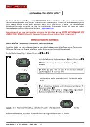
<strong>FGR</strong> <strong>710</strong> - External adjustments<br />
The Öhlins <strong>FGR</strong> <strong>710</strong> <strong>Front</strong> <strong>Fork</strong> is equipped<br />
with the following external adjusters:<br />
• Spring preload adjuster<br />
• Rebound damping adjuster<br />
• Compression damping adjuster<br />
1<br />
2<br />
3<br />
Spring preload adjuster<br />
Adjust the spring preload by turning<br />
the nut on top of the fork leg. Use a<br />
14 mm wrench.<br />
Adjustment range: 0-18 mm.<br />
On the adjustment nut, one turn will<br />
change 1 mm in spring preload.<br />
Recommended static sag is 15-25 mm.<br />
Rebound adjuster<br />
Adjust the rebound damping by turning<br />
the screw at the top of the front fork. Use<br />
tool 00794-01.<br />
Adjustment range, from closed<br />
valve (clockwise) until maximum open<br />
valve (counter clockwise): 20 clicks.<br />
Recommended adjustment “click”, from<br />
closed position: See specification card.<br />
Compression adjuster<br />
Adjust the compression damping by<br />
turning the screw at the fork bottom.<br />
Use a flat screwdriver.<br />
Adjustment range, from closed<br />
valve (clockwise) to maximum<br />
open valve (counter clockwise): 20 clicks”.<br />
Recommended adjustment “click”, from<br />
closed position: See specification card.<br />
Increase<br />
spring preload<br />
14 mm wrench<br />
Tool 0079 -01<br />
Reduce<br />
spring preload
R1<br />
Basic Guidelines<br />
How to set up your Öhlins front forks<br />
The front forks are just one part of your<br />
motorcycle and to get it to work properly, you<br />
have to adjust the front and rear suspension<br />
together.<br />
1<br />
Put the motorcycle on a workstand and install<br />
the Öhlins front fork.<br />
NOTE!<br />
The lower triple clamp must not be tightened to<br />
more than 12-15 Nm. This is also important for the<br />
steering damper bracket, when located around<br />
the upper front leg. Too high torque may deform<br />
the front fork leg.<br />
Guidelines<br />
Setting the Spring preload<br />
The spring preload is very important since it<br />
affects the height of the motorcycle and the fork<br />
angle. Consequently, handling characteristics<br />
can be changed, even negatively.<br />
Increase<br />
spring preload<br />
14 mm<br />
wrench<br />
Reduce<br />
spring preload<br />
F1<br />
R<br />
Procedure<br />
We recommend you to have an assistant for this<br />
procedure.<br />
1.<br />
2.<br />
3.<br />
4.<br />
5.<br />
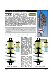
<strong>FGR</strong> <strong>710</strong> - Setting up your forks<br />
Put the motorcycle on a stand.<br />
Make sure that the shock absorber is fully<br />
extended.<br />
Measure the distance from the lower edge of the<br />
rear mud guard or from a point marked by a piece<br />
of tape, immediately above the rear wheel axle, to<br />
the wheel axle. (R1)<br />
Make a similar measurement on the front axle, for<br />
example, from the bottom of the upper fork crown<br />
to the front wheel axle. Make sure that the front<br />
fork is fully extended. (F1)<br />
Take the same measurements with the rider and<br />
equipment on the motorcycle. It is important that<br />
the rider has a correct riding posture, so that the<br />
weight is balanced on the front and rear wheel in<br />
the same way as when riding (R3, F3).<br />
The measurements should not differ from the<br />
following:<br />
With rider:<br />
Rear: 30±5 mm (R1-R3)<br />
<strong>Front</strong>: 30±5 mm (F1-F3)<br />
Without rider:<br />
Rear: Just top out 0 mm (R1-R2)<br />
<strong>Front</strong>: 15-25 mm (F1-F2)<br />
NOTE!<br />
An <strong>RR</strong>125 cannot afford to loose the momentum<br />
that the sag would give in a straight line (loss of<br />
top speed).<br />
Bike on a stand. Bike on the ground.<br />
Bike with rider on.<br />
F<br />
R<br />
F
<strong>FGR</strong> <strong>710</strong> - Tools and oils<br />
Recommended tools and oils<br />
1. Vice<br />
. Soft jaws 007 7-0 (one pair)<br />
. Hexagon screwdriver 0079 -01<br />
. Wrench: 14 mm, 17 mm, 19 mm<br />
and 24 mm.<br />
. Wire with hook<br />
. Seal head tool 01797-08<br />
7. Heat gun<br />
8. Brass wire brush<br />
9. Sleeve pin 00797-01<br />
10. Inner fork leg tool 0078 -0<br />
11. Attachment bar 017 7-01<br />
1 . Pull-up spring tool 017 -0<br />
1 . Rag<br />
1 . Öhlins red grease 001 -01<br />
1 . Öhlins front fork oil 01 11-01<br />
1 . Waste oil container<br />
Loctite 2701<br />
1 2<br />
10<br />
13<br />
16<br />
4<br />
6<br />
8 9<br />
12<br />
14<br />
3<br />
11<br />
5<br />
15<br />
7
1.1<br />
Release the spring preload completely by turning<br />
the adjustment nut counter clockwise as far as<br />
possible. Use a 14 mm wrench or socket.<br />
1.<br />
Loosen the screws that hold the fork legs in the<br />
upper triple clamps.<br />
1.<br />
Loosen the top nut assembly from the fork leg.<br />
Use tool 00797-01.<br />
1.<br />
Remove the top nut assembly from the piston<br />
shaft. Use a 14 mm wrench on the top nut and a<br />
19 mm on the shaft.<br />
1.<br />
Remove the spring support and the spring. Use<br />
a wire with a hook and carefully pull out the<br />
preload tube.<br />
1.<br />
Check the oil level according to Chapter Oil level<br />
adjustment.<br />
NOTE!<br />
Use Öhlins <strong>Front</strong> fork oil 01311-01 only.<br />
1.7<br />
Reinstall the preload tube, the new spring and<br />
the spring support.<br />
1.8<br />
Reinstall the top nut assembly to the piston shaft<br />
with tightening torque 20 Nm.<br />
1.9<br />
Reinstall the top nut into the outer fork leg, with<br />
the front wheel off the ground (use tool 00797-<br />
01) and tighten with torque 10 Nm. Tighten<br />
the upper triple clamps and adjust the preload<br />
according to Chapter External adjustments.<br />
Work section - 1. Change the spring<br />
7<br />
14 mm<br />
wrench<br />
Preload tube<br />
Fig. 1.1<br />
Fig. 1.<br />
Fig. 1.<br />
Tool<br />
00797-01<br />
Spring<br />
support<br />
Spring<br />
20 Nm<br />
Tool<br />
00797-01<br />
14 mm<br />
wrench<br />
19 mm<br />
wrench<br />
Fig. 1.9<br />
Fig. 1.<br />
Fig. 1.<br />
Fig. 1.8
Work section - . Dissasemble the front fork<br />
NOTE!<br />
This worksection can not be done while the forks<br />
still are installed on the motorcycle.<br />
.1<br />
Put the fork legs in upright position for about 5<br />
minutes to allow the oil to settle.<br />
.<br />
Fasten the fork leg in a vice with soft jaws.<br />
.<br />
Release the spring preload completely by turning<br />
the adjustment nut counter clockwise as far as<br />
possible. Use a 14 mm wrench or a socket.<br />
NOTE!<br />
Do not use the preload adjuster to tighten or<br />
loosen the top nut assembly.<br />
.<br />
Loosen the top nut assembly. Use tool 00797-01.<br />
.<br />
Remove the top nut assembly from the piston<br />
shaft. Use a 14 mm wrench to the top nut and a<br />
19 mm wrench to the shaft.<br />
.<br />
Remove the spring support and the spring. Use a<br />
wire with a hook and carefully pull up the preload<br />
tube.<br />
.7<br />
Use tool 01797-08 together with an 24mm wrench<br />
to unscrew the piston rod unit from the fork leg.<br />
.8<br />
Use tool 01765-03 to remove the piston rod unit.<br />
.9<br />
Drain all oil from the fork leg. Make sure that<br />
washer 04729-02 falls out.<br />
8<br />
Fig. .<br />
Fig. .<br />
Piston<br />
rod unit<br />
14 mm<br />
wrench<br />
Fig. .8<br />
Spring support<br />
Spring<br />
Preload tube<br />
Fig. .<br />
14 mm<br />
wrench<br />
19 mm<br />
wrench<br />
24 mm<br />
wrench<br />
<strong>Fork</strong> leg<br />
Tool<br />
00797-01<br />
Fig. .<br />
Fig. .<br />
Fig. .7<br />
Washer<br />
Fig. .9
NOTE!<br />
This worksection can not be done while the forks<br />
still are installed on the motorcycle.<br />
Remove the top nut and piston rod unit<br />
according to Chapter . Disassemble the <strong>Front</strong><br />
<strong>Fork</strong>. Then, continue below.<br />
.1<br />
Remove the outer fork leg, clean the seal and<br />
check the condition. If the seal is in good<br />
condition apply some red grease (00146-01) to<br />
the seal before reassembling the fork.<br />
A damaged seal must be replaced!<br />
.<br />
Remove the circlip, the seal and finally the<br />
washer.<br />
.<br />
Apply a thin layer of Öhlins red grease (00146-<br />
01) to the washer and to the sealing surfaces<br />
of the fork seal. Install the washer and the seal<br />
into the outer fork leg. Install the circlip into the<br />
groove.<br />
NOTE!<br />
It is important to use the correct grease in order to<br />
achieve optimum fork function.<br />
.<br />
Apply some Öhlins fork oil (01311-01) on the<br />
inner fork legs outer surface. Slide on the outer<br />
fork legs carefully on to the inner fork legs<br />
(completely down).<br />
WARNING!<br />
Be careful - Do not damage the fork seal!<br />
.<br />
Reassemble the fork legs according to Chapter<br />
. Assemble the <strong>Front</strong> fork.<br />
9<br />
Work section - . Change the seals<br />
3) Circlip<br />
2) Seal<br />
1) Washer<br />
Fig. .<br />
Fig. .1<br />
1) Circlip<br />
2) Seal<br />
3) Washer<br />
Fig. .<br />
NOTE!<br />
Red grease<br />
Öhlins<br />
fork oil<br />
Fig. .<br />
Tire lever or<br />
equivalent<br />
Outer fork<br />
leg<br />
Inner fork<br />
leg
NOTE!<br />
This worksection can not be done while the forks<br />
still are installed on the motorcycle.<br />
Remove the top nut and piston rod unit<br />
according to Chapter . Disassemble the <strong>Front</strong><br />
<strong>Fork</strong>. Then, continue below.<br />
.1<br />
Remove the outer fork leg.<br />
.<br />
Use a heat gun to warm up the fork bottom.<br />
Use tool 00786-02 to unscrew and remove the<br />
inner fork leg. Clean the threads thoroughly from<br />
Loctite.<br />
.<br />
Install the new inner fork leg using tool 00786-<br />
02. Use Loctite 2701 on the threads. Tighten<br />
with torque to 160 Nm.<br />
.<br />
Apply some Öhlins fork oil (01311-01) on the<br />
inner fork legs outer surface. Slide on the outer<br />
fork legs on to the inner fork legs (completely<br />
down).<br />
WARNING!<br />
Be careful - Do not damage the fork seal!<br />
.<br />
Work section - . Replace the inner fork legs<br />
Reassemble the fork legs according to Chapter<br />
. Assemble the <strong>Front</strong> <strong>Fork</strong>.<br />
10<br />
Fig. .1<br />
Öhlins<br />
fork oil<br />
Outer fork leg<br />
Inner fork leg<br />
Outer fork leg<br />
Inner fork leg<br />
Fig. .<br />
Tool<br />
00786-02<br />
Fig. .
.1<br />
Assemble the compression valve assembly to<br />
the cylinder tube. Smear some red grease on<br />
washer 04729-02 and stick it to the bottom of<br />
the base valve.<br />
.<br />
Assemble the piston rod unit into the fork leg<br />
and tighten with 20Nm. Use tool 01797-08.<br />
.<br />
Pour Öhlins <strong>Front</strong> <strong>Fork</strong> Oil 01311-01 into the<br />
inner fork leg, approximately 20-25 mm above<br />
the cylinder tube.<br />
.<br />
Pull the rod up and down and make sure that<br />
there is no air left. Use tool 01765-03.<br />
.<br />
Push tool 01765-03 to a stop and check the oil<br />
level according to Chapter Oil level adjustment.<br />
NOTE!<br />
Use Öhlins <strong>Front</strong> <strong>Fork</strong> oil 01311-01 only!<br />
.<br />
Reinstall the preload tube. Install the spring and<br />
the spring support.<br />
.7<br />
Reinstall the top nut assembly to the piston<br />
shaft. Tightening torque 20 Nm.<br />
.8<br />
Reinstall the top nut into the outer fork leg. Use<br />
tool 00797-01 and tighten with torque 10 Nm.<br />
Adjust the spring preload, compression and<br />
rebound damping.<br />
Work section - . Assemble the front fork<br />
11<br />
Fig. .1<br />
20 Nm<br />
Compr.<br />
valve<br />
assy<br />
Washer<br />
20 Nm<br />
Piston<br />
rod<br />
Fig. .<br />
Fig. .<br />
Fig. .7<br />
Tool<br />
00797-01<br />
20-25 mm<br />
Fig. .<br />
Fig. .<br />
10 Nm<br />
Fig. .8
Oil level adjustment<br />
Compared with conventional type of front forks,<br />
the upside down front forks are very sensitive<br />
to variations in oil level. Therefore, adjust the oil<br />
level with special care.<br />
A change in the fork oil level will not affect the<br />
spring force at the beginning of the fork travel,<br />
but will have a great effect at the end of the<br />
travel.<br />
When the oil level is raised:<br />
The air spring in the later half stage of travel<br />
is stronger, and make the front forks more<br />
progressive.<br />
When the oil level is lowered:<br />
The air spring of the travel is reduced, and thus<br />
the front fork less progressive. The oil level<br />
works most efficient at the end of the fork travel.<br />
Air spring characteristics shown, is a general<br />
card description to understand the difference<br />
when the oil level is changed.<br />
NOTE!<br />
Adjust the oil level according to the figure with<br />
the fork leg fully compressed (with springs and<br />
preload tube taken out). For the correct oil level<br />
- see specification card.<br />
1<br />
Push to a stop,<br />
use tool 01765-03<br />
Fig. .<br />
Öhlins <strong>Front</strong> <strong>Fork</strong><br />
fluid 01311-01<br />
The edge of the<br />
outer fork leg<br />
Check the<br />
oil level
<strong>Front</strong> <strong>Fork</strong> length 1 mm<br />
Stroke 100 mm<br />
Free spring length 0 mm<br />
Recommended settings<br />
Compression: 10 clicks<br />
Rebound: 12 clicks<br />
Spring preload: 4 turns from fully compressed<br />
position<br />
Preload range: 0-15 mm (0-15 turns)<br />
Spring rate<br />
21610-55 5.5 N/mm<br />
Optional springs available<br />
21610-50 5.0 N/mm<br />
21610-60 6.0 N/mm<br />
21610-65 6.5 N/mm<br />
21610-70 7.0 N/mm<br />
Oil capacity<br />
See specification card.<br />
Use Öhlins high performance front fork<br />
oil no. 4 (01311-01) only.<br />
1<br />
Torque<br />
Technical information<br />
Lower triple clamp bolt 12-15 Nm<br />
Upper triple clamp bolt 18-22 Nm<br />
Grease<br />
Öhlins <strong>Front</strong> <strong>Fork</strong><br />
Red Grease 00146-01<br />
Service intervals<br />
This product is designed for racing use<br />
only.<br />
Recommended service every 10 hours.<br />
Disposal<br />
Discarded products should be handed over<br />
to an authorized Öhlins Service Centre for<br />
proper disposal.
Below you will find a few examples of how<br />
to adjust for the most common road holding<br />
problems in Road Racing driving.<br />
1<br />
Troubleshooting<br />
The front wheel “chatters” entering a corner,<br />
the problem goes away, as soon as you let the<br />
brakes off, or when you get on the power.<br />
• This is caused by the fact that the fork is<br />
working too low in the travel and reaches the<br />
progressive, hard part at the end of the travel.<br />
• Put on more preload.<br />
• Change to a harder spring.<br />
• If a lot of stroke remains after riding, drop the<br />
oil level. See oil level chart.<br />
• Make sure the front forks have no friction.<br />
• Rear ride height is to high, too much rear<br />
spring preload.<br />
• Lower the rear end by taking off preload<br />
from rear shock spring.<br />
1<br />
The front wheel is jumping during the last part of<br />
braking.<br />
• If a lot of stroke remains, the oil level is too<br />
high. Lower the oil level.<br />
• If the fork is bottoming, put in harder springs<br />
and keep the oil level.<br />
1<br />
The front end feels unpredictable and un-safe in<br />
the middle of the corner (between braking and<br />
getting on power).<br />
• Not enough rebound damping. Put on more<br />
damping.<br />
• Too much rebound damping. If it at the<br />
same time feels harsh, take off some rebound<br />
damping.<br />
• Too much compression damping. Also gives<br />
a harsh feeling. Take off some compression<br />
damping.<br />
The front end loses grip coming out of a corner.<br />
• Not enough rebound damping. Put on some<br />
more rebound damping.<br />
• Too much preload. Take off some preload.<br />
• Rear end is too soft. Put on a harder rear<br />
spring.<br />
• <strong>Front</strong> end is too high. Lower the front end by<br />
pulling the fork legs through the triple clamps.<br />
As mentioned in the beginning, the whole bike<br />
setup affects the front forks. Try to understand<br />
the feelings and work step by step.<br />
NOTE!<br />
We advise to change only one thing at a time and<br />
do everything step by step.<br />
4
Pos Part No. Pcs Description Remarks<br />
1-1 - - Top nut assembly See page 16<br />
1-2 03316-01 2 Spring support<br />
1-3<br />
21610-55<br />
21610-50<br />
21610-60<br />
21610-65<br />
21610-70<br />
2<br />
2<br />
2<br />
2<br />
2<br />
Spring<br />
Option spring<br />
Option spring<br />
Option spring<br />
Option spring<br />
1-4 21611-01 2 Guide ring<br />
1-5 01460-50 2 Preload tube<br />
1-6 01550-03 2 <strong>Fork</strong> leg outer<br />
1-7 01683-03 2 Bushing<br />
1-8 01684-03 2 Bushing<br />
1-9 02463-01 2 Washer<br />
1-10 02461-01 2 Seal MX<br />
1-11 02465-01 2 Circlip<br />
1-12 21606-01 2 Cylinder tube<br />
1-13 02469-03 2 <strong>Fork</strong> leg inner<br />
1-14 01902-17 1 <strong>Fork</strong> bottom LH Left<br />
1-15 01902-18 1 <strong>Fork</strong> bottom RH Right<br />
1-16 01046-02 4 Screw<br />
1-17 01669-01 2 Sleeve<br />
1-18 01473-02 2 Circlip<br />
1-19 00338-53 2 O-ring<br />
1-20 01242-03 2 Adjustment needle<br />
1-21 01474-01 2 Spring<br />
1-22 00884-02 4 Ball<br />
Note! The number of pieces is<br />
valid for 1 pair of <strong>Front</strong> fork legs<br />
4.0/163/5.5<br />
4.0/158/5.0<br />
4.2/154/6.0<br />
4.2/157/6.5<br />
4.4/148/7.0<br />
1<br />
1 -<br />
-<br />
-<br />
-<br />
-<br />
-<br />
7 -<br />
8 -<br />
9 -<br />
10 -<br />
11 -<br />
1<br />
1 -<br />
1 -<br />
17<br />
0<br />
1<br />
Spare parts list<br />
17<br />
1<br />
19<br />
18<br />
1<br />
0<br />
1<br />
1<br />
Fig.1<br />
19<br />
18
Spare parts list<br />
Pos Part No. Pcs Description Remarks<br />
2-1 01473-01 2 Circlip<br />
2-2 00577-01 2 O-ring<br />
2-3 01467-02 2 Adjustment screw<br />
2-4 00884-04 4 Ball<br />
2-5 01474-01 2 Spring<br />
2-6 03312-01 2 Adjuster<br />
2-7 03309-01 4 Shim t=0,1mm<br />
2-8 00338-72 2 O-ring<br />
2-9 03318-09 2 Adjustment housing<br />
2-10 00338-92 2 O-ring<br />
2-11 03317-01 6 Spring<br />
2-12 03309-02 2 Shim t=0,38mm<br />
2-13 03313-01 2 Nut<br />
2-14 03315-01 2 Preload socket<br />
2-15 00382-06 2 Screw<br />
2-16 00338-56 2 O-ring<br />
Note! The number of pieces is<br />
valid for 1 pair of <strong>Front</strong> fork legs<br />
1<br />
6 -<br />
7 -<br />
8 -<br />
9 -<br />
10 -<br />
7 -<br />
11 -<br />
12 -<br />
13 -<br />
14 -<br />
Top nut assembly<br />
1 -<br />
2 -<br />
3 -<br />
4<br />
5<br />
4<br />
15<br />
16<br />
Fig.
Pos Part No. Pcs Description Remarks<br />
3-1 02366-16 2 Adjustment rod<br />
3-2 03314-12 2 Shaft extension<br />
3-3 00338-76 2 O-ring<br />
3-4 02302-10 2 Spring guide<br />
3-5 01582-12 4 Spacer<br />
3-6 01582-10 2 Spacer<br />
3-7 01580-01 2 Bump rubber<br />
3-8 21607-01 2 Tube top cap<br />
3-9 00110-01 2 Bushing<br />
3-10 00438-28 2 O-ring<br />
3-11 01582-12 4 Spacer<br />
3-12 02367-09 2 Shaft<br />
3-13 00438-31 2 O-ring<br />
3-14 01698-10 2 Rebound needle<br />
3-15 02322-01 2 Spring<br />
3-16 01654-11 2 Piston holder<br />
3-17 - - Shim stack See spec. card<br />
3-18 02061-03 2 Piston, rebound<br />
3-19 01447-02 2 Piston ring<br />
3-20 - - Shim stack See spec. card<br />
3-21 - - Washer See spec. card<br />
3-22 00153-01 2 Washer<br />
3-23 01675-01 2 Nut<br />
Note! The number of pieces is<br />
valid for 1 pair of <strong>Front</strong> fork legs<br />
17<br />
1 -<br />
-<br />
-<br />
-<br />
-<br />
-<br />
7 -<br />
8 -<br />
9 -<br />
10 -<br />
11 -<br />
1 -<br />
Spare parts list<br />
Rebound valve assembly<br />
1 -<br />
1 -<br />
1 -<br />
1 -<br />
17 -<br />
18 -<br />
19 -<br />
0 -<br />
1 -<br />
-<br />
-<br />
Fig.
Spare parts list<br />
Pos Part No. Pcs Description Remarks<br />
4-1 00520-26 2 Shim<br />
4-2 21609-01 2 Base valve<br />
4-3 - - Washer See spec. card<br />
4-4 - - Shim stack See spec. card<br />
4-5 01670-04 2 Piston<br />
4-6 00438-02 2 O-ring<br />
4-7 01669-01 2 Sleeve<br />
4-8 00530-22 2 Shim<br />
4-9 01671-02 2 Spring<br />
4-10 01672-01 2 Spring collar<br />
4-11 00120-01 2 Washer<br />
4-12 01675-01 2 Nut<br />
Note! The number of pieces is<br />
valid for 1 pair of <strong>Front</strong> fork legs<br />
18<br />
Compression valve assembly<br />
1 -<br />
2 -<br />
3 -<br />
4 -<br />
5 -<br />
6 -<br />
7 -<br />
8 -<br />
9 -<br />
10 -<br />
11 -<br />
12 -<br />
Fig.
www.ohlins.com
Your Öhlins retailer:<br />
Öhlins Racing AB<br />
Box 722<br />
SE-194 27, Upplands Väsby<br />
Sweden<br />
Phone: +46 (0)8 590 025 00<br />
Fax: +46 (0)8 590 025 80<br />
www.ohlins.com<br />
Öhlins Owner’s Manual <strong>FGR</strong> <strong>710</strong>| Part No. 07280-14_3 | Issued 2009-02-16 | © 2009 Öhlins Racing AB